stinger® copper loop test (clt) module guide service stinger® copper loop test (clt) module guide...
TRANSCRIPT

Stinger®Copper Loop Test (CLT) Module Guide
363-217-035R9.9.0For software version 9.9.0
February 2006

Copyright © 2000, 2001, 2002, 2003, 2004, 2006 Lucent Technologies Inc. All rights reserved.
This material is protected by the copyright laws of the United States and other countries. It may not be reproduced, distributed, or altered in any fashion by any entity (either internal or external to Lucent Technologies), except in accordance with applicable agreements, contracts, or licensing, without the express written consent of Lucent Technologies. For permission to reproduce or distribute, please email your request to [email protected].
Notice
Every effort was made to ensure that the information in this document was complete and accurate at the time of printing, but information is subject to change.
European Community (EC) RTTE compliance
Hereby, Lucent Technologies, declares that the equipment documented in this publication is in compliance with the essential require-ments and other relevant provisions of the Radio and Telecommunications Technical Equipment (RTTE) Directive 1999/5/EC.
To view the official Declaration of Conformity certificate for this equipment, according to EN 45014, access the Lucent INS online documentation library at http://www.lucentdocs.com/ins.
Safety, compliance, and warranty Information
Before handling any Lucent Access Networks hardware product, read the Edge Access Safety and Compliance Guide included in your product package. See that guide also to determine how products comply with the electromagnetic interference (EMI) and network compatibility requirements of your country. See the warranty card included in your product package for the limited warranty that Lucent Technologies provides for its products.
Security statement
In rare instances, unauthorized individuals make connections to the telecommunications network through the use of access features.
Trademarks
Lucent, the Lucent logo, and all Lucent brand and product names are trademarks or registered trademarks of Lucent Technologies Inc. Other brand and product names are trademarks of their respective holders.
Ordering Information
You can order the most up-to-date product information and computer-based training online at http://www.lucentdocs.com/bookstore.
Feedback
Lucent Technologies appreciates customer comments about this manual. Please send them to [email protected].
Lucent Technologies

Customer Service
Stinger® Copper Loop Test (CLT) Module Guide iii
Customer ServiceProduct and service information, and software upgrades, are available 24 hours a day. Technical assistance options accommodate varying levels of urgency.
Finding information and software
To obtain software upgrades, release notes, and addenda for this product, log in to Lucent OnLine Customer Support at http://www.lucent.com/support.
Lucent OnLine Customer Support also provides technical information, product information, and descriptions of available services. The center is open 24 hours a day, seven days a week. Log in and select a service.
Obtaining technical assistance
Lucent OnLine Customer Support at http://www.lucent.com/support provides access to technical support. You can obtain technical assistance through email or the Internet, or by telephone. If you need assistance, make sure that you have the following information available:
■ Active service or maintenance contract number, entitlement ID, or site ID
■ Product name, model, and serial number
■ Software version
■ Software and hardware options If supplied by your carrier, service profile identifiers (SPIDs) associated with your line
■ Your local telephone company’s switch type and operating mode, such as AT&T 5ESS Custom or Northern Telecom National ISDN-1
■ Whether you are routing or bridging with your Lucent product
■ Type of computer you are using
■ Description of the problem
Obtaining assistance through email or the Internet
If your services agreement allows, you can communicate directly with a technical engineer through Email Technical Support or a Live Chat. Select one of these sites when you log in to http://www.lucent.com/support.
Calling the technical assistance center (TAC)
If you cannot find an answer through the tools and information of Lucent OnLine Customer Support or if you have a very urgent need, contact TAC. Access Lucent OnLine Customer Support at http://www.lucent.com/support and click Contact Us for a list of telephone numbers inside and outside the United States.
Alternatively, call 1-866-LUCENT8 (1-866-582-3688) from any location in North America for a menu of Lucent services. Or call +1 510-769-6001 for an operator. If you do not have an active services agreement or contract, you will be charged for time and materials.


Contents
Customer Service ........................................................................................................iii
Chapter 1 Overview of the CLT Module and Copper Loop Testing................1-1
Overview of CLT module capabilities....................................................................... 1-1Copper loop test devices........................................................................................... 1-2Metallic loop testing ................................................................................................. 1-2
Prequalification tests .......................................................................................... 1-3Troubleshooting and maintenance support ....................................................... 1-4
CLT module installation ........................................................................................... 1-4System description ................................................................................................... 1-5System operation...................................................................................................... 1-5Supported tests ......................................................................................................... 1-7
DMM tests.......................................................................................................... 1-7Line tests ............................................................................................................ 1-8TDR tests .......................................................................................................... 1-10Other functions and commands ...................................................................... 1-11
How to perform tests.............................................................................................. 1-12
Chapter 2 Copper Loop Testing through the Command-Line Interface.........2-1
Using the command-line interface ........................................................................... 2-1Performing tests using clt commands ................................................................ 2-1Performing tests using clt-ms-access profile.................................................... 2-1
Activating tester and copper loop access .................................................................. 2-2Enabling test access with the cltactivate command ....................................... 2-2Enabling test access through the clt-ms-access profile.................................... 2-5Enabling loop testing with one CLT module and multiple Stinger units........... 2-7Specifying a timeout value for copper loop access ............................................ 2-8Extending the duration of copper loop test access ............................................ 2-8
Viewing copper loop access results........................................................................... 2-9Selecting a test........................................................................................................ 2-10
Selecting tests using the cltcmd command ...................................................... 2-10Selecting tests using the clt-command profile................................................... 2-24
Determining test results ......................................................................................... 2-33
Chapter 3 Copper Loop Testing through SNMP...............................................3-1
Ascend-CLTM-MIB groups........................................................................................... 3-1CLT module access group—cltmAccess .....................................3-1CLT module command group—cltmCmd.....................................3-3CLT module results group—cltmRslt ......................................3-14
The Stinger® Compact Remote ATM DSLAM Getting Started Guide v

Contents
Appendix A CLT Module Specifications...............................................................A-1
Physical specifications ..............................................................................................A-1Connector pinouts and specifications.......................................................................A-2
Serial connector .................................................................................................A-2TEST PAIR connector.........................................................................................A-3AUX connector ..................................................................................................A-3Port connector ...................................................................................................A-4
Index .....................................................................................................1
vi The Stinger® Compact Remote ATM DSLAM Getting Started Guide

1Overview of the CLT Module and Copper Loop Testing
The Stinger copper loop test (CLT) module allows a Stinger administrator to individually test copper loop pairs terminated on Stinger line protection modules (LPMs). The built-in test head performs the necessary analog and digital tests to qualify and maintain copper loops. You can test each pair without disconnecting any cables. Copper loop testing can also be conducted through the use of an external head and a path selector module (PSM).
Overview of CLT module capabilitiesThe CLT module has a built-in test head that can perform the following tests:
■ Digital multimeter (DMM) tests—measure ac and dc voltage, dc delta, resistance, loop resistance, capacitance, and loop length.
■ Line tests—measure wideband noise, impulse noise, load coil detection, loop resistance, insertion loss and signal to noise.
■ Time-domain reflectometry (TDR) tests—locate bridgetaps, load coils, water-saturated cable sections, short circuits, and cable faults.
■ Tone and signaling tests—measure send and receive tones and detect signals and voice.
Most tests supported are single ended and do not require equipment or termination at the customer premises equipment (CPE) end of the loop. Insertion loss, signal-to-noise, and detap tests require the use of additional equipment at the CPE end of the loop. The loop resistance test requires that the loop be shorted at the CPE end.
Overview of CLT module capabilities . . . . . . . . . . . . . . . . . . . . . . . . . . . . . . . . . . 1-1
Copper loop test devices. . . . . . . . . . . . . . . . . . . . . . . . . . . . . . . . . . . . . . . . . . . . 1-2
Metallic loop testing . . . . . . . . . . . . . . . . . . . . . . . . . . . . . . . . . . . . . . . . . . . . . . . 1-2
CLT module installation . . . . . . . . . . . . . . . . . . . . . . . . . . . . . . . . . . . . . . . . . . . . 1-4
System description . . . . . . . . . . . . . . . . . . . . . . . . . . . . . . . . . . . . . . . . . . . . . . . . 1-5
System operation . . . . . . . . . . . . . . . . . . . . . . . . . . . . . . . . . . . . . . . . . . . . . . . . . 1-5
Supported tests . . . . . . . . . . . . . . . . . . . . . . . . . . . . . . . . . . . . . . . . . . . . . . . . . . . 1-7
How to perform tests . . . . . . . . . . . . . . . . . . . . . . . . . . . . . . . . . . . . . . . . . . . . . 1-12
Stinger® Copper Loop Test (CLT) Module Guide 1-1

Overview of the CLT Module and Copper Loop TestingCopper loop test devices
Testing by the built-in test head can be initiated through the TAOS command-line interface (CLI) or Simple Network Management Protocol (SNMP). Test results are reported through a TAOS profile or SNMP.
For physical specifications and pinouts, see Appendix A, “CLT Module Specifications.”
Copper loop test devicesTable 1-1 summarizes Stinger devices with copper loop testing capabilities.
Copper loop test modules use a test head with extended capabilities and support up to 72 ports per LIM. The STGR-CLTE model can be used with both the Stinger FS and FS+ chassis. When you install a STGR-CLTE module in a Stinger FS chassis, you can only use ports 1 through 48. The STGRLS-CLTE-72 and STGRRT-CLTE-72 modules are designed for use with the Stinger LS and RT, respectively. They support testing with LIMs that have up to 72 ports.
The 48-port line protection module (LPM) with integrated splitters also provides line prequalification capabilities. For more information about 48-port LPM test connections and how to configure test access using the 48-port LIM, see the Stinger Line Protection (LPM) Module Guide.
Metallic loop testingMetallic loop testing is used to prequalify, install, and maintain xDSL loops. Various tests can be used to ensure that a particular loop can support the desired xDSL protocol. The CLT module has the capability to perform these tests.
Two methods of testing exist, single-ended and double-ended. Single-ended tests require test equipment at only the central office (CO) or digital loop carrier (DLC) end of the loop. Double-ended testing requires additional equipment and the presence of a technician at the customer premise equipment (CPE) end as well.
Table 1-1. Devices for copper loop testing
Device Product Code Stinger chassis
Stinger Copper Loop Test Module
STGR-CLTE FS, FS+
STGRLS-CLTE LS-1, LS-2
STGRRT-CLTE RT-1, RT-2
Path Selector Module STGR-PSM2 FS+
STGRLS-PSM2-72 LS-1
STGRRT-PSM2-72 RT
Stinger 48-port line protection module (LPM) with splitters
STGR-LPM2-48-S FS, FS+
STGRLR-LPM2-48-S LS-1, LS-2, RT-1, RT-2
STGRCR-LPM2-48-S CR
1-2 Stinger® Copper Loop Test (CLT) Module Guide

Overview of the CLT Module and Copper Loop TestingMetallic loop testing
Prequalification testing is performed to determine if a particular loop can support an xDSL service before installation. Single-ended tests from the CO can provide up to a 95% confidence level that a loop will support xDSL services when installed.
Installation and maintenance tests are used to support existing xDSL installations. These tests are typically used to troubleshoot problems that suddenly occur on a particular loop. Most often, problems result from deterioration, accidental breaks, or splices in cables.
Prequalification testsThe following prequalification tests are single ended.
Line length measurement
The performance of xDSL signals is sensitive to the distance between the CO and the customer. A reasonable estimation of line length can be made using a single-ended capacitance measurement.
Load coil detection
Load coils are inductors that have been added to subscriber loops of more than 18,000 feet (5486 meters) to improve voice quality. If present, load coils completely block transmission of xDSL signals. Over the years, as old loops have been rearranged, many unneeded load coils have been left on existing copper loops.
Load coil detection determines the number of load coils and their distance from the CO. A technician can be dispatched to remove unneeded coils and make the loop available for xDSL use.
Noise measurement
Wideband and impulse noise measurement is used to detect signals and other transmissions in the same binder group. Analysis of the noise frequencies can help identify the exact source of the noise. Particular frequencies can adversely affect the performance of certain xDSL services.
Metallic fault tests
Metallic fault tests include the measurement of dc and ac voltage, resistance, and capacitance. DC and AC Thevenin loop resistance tests are also available. Measurements can be made tip-to-ring, tip-to-ground, and ring-to-ground. In addition to the detection of such faults as foreign voltages, metallic testing can assess the balance of each line. Imbalance of tip-to-ground and ring-to-ground parameters can adversely affect xDSL performance.
Bridge tap detection
A bridge tap is any unterminated part of a loop that is not in the direct path between the CPE and the CO. Bridge taps are typically abandoned connections that were used to provide additional services to a customer’s premises. A very long bridge tap—more than 6000 feet (1830 meters)—can affect xDSL performance.
Stinger® Copper Loop Test (CLT) Module Guide 1-3
Overview of the CLT Module and Copper Loop TestingCLT module installation
Splitter detection
Splitters separate the analog telephone service signal and the DSL signal. Detection of splitters is a useful diagnostic tool because the presence of a splitter with dc blocking capacitors can sometimes cause inaccurate copper loop test results.
Splitter bypass
If a splitter with dc blocking capacitors is present in the loop circuit, dc voltage, isolation, and loop resistance testing cannot be performed. You can use this feature to set certain brands of splitters to bypass mode.
Troubleshooting and maintenance support Many of the prequalification tests can be used to troubleshoot xDSL loop failures. TDR testing can be used to detect cable faults including shorts, opens, and damaged sections.
CLT module installationThe CLT module is installed in place of an line protection module (LPM) behind (Stinger FS or Stinger FS+) or next to (Stinger LS or Stinger RT) the slot chosen for an optional spare line interface module (LIM). With a Stinger FS or Stinger FS+ unit, the slot in front of the CLT module must either be empty or used for a spare LIM.
With the Stinger LS or Stinger RT unit, the slot to the left of the CLT can still be used for an active LIM if desired. Individual ports on this LIM can be either active or redundant.
If no spare LIM is used, for the Stinger FS or Stinger FS+, testing can be performed in looking-out mode but not in bridging mode. Testing can be done in either mode for the Stinger LS or Stinger RT. All LIMs must use a line protection module (LPM) with port redundancy (LPM-RP). Table 1-2 shows the required modules for different test modes.
For hosted Stinger systems, a Compact Remote unit installed with a 48-port LPM with splitters provides test access to the ADSL copper facilities through an RJ-11 test connector at the top of the module. This test connector can be used as an access point for testing any ADSL line served by any LPM in a Stinger Compact Remote chassis. On a Compact Remote unit, only a single test session can be in progress at any time. For information about physical connections, see the Stinger Compact Remote Installation and Configuration Guide.
If you are using an external test head, a port selector module (PSM) can be installed in place of the CLT. The PSM contains the necessary circuitry to select and connect the copper loop to be tested to external terminals on the PSM. See “TEST PAIR connector” on page A-3 for more information. You can connect the external test head to these terminals to complete the test circuit.
1-4 Stinger® Copper Loop Test (CLT) Module Guide
Overview of the CLT Module and Copper Loop TestingSystem description
System descriptionThe CLT module consists of a PSM motherboard combined with a daughterboard containing the test head. Administrators who wish to perform tests with an external test head can use a PSM alone.
The CLT module or PSM is equipped to access any port on any LIM that is equipped with an LPM-RP. Most users equip all the LIMs in their system with LPM-RPs. Most users also have a redundant (spare) LIM installed in front of or next to the CLT module.
LIMs and LPMs install into the midplane in the Stinger chassis. The midplane contains trace pairs that can be accessed by both LIMs and LPMs. Both the CLT or PSM and the LPM-RPs behind each LIM contain relays that can be switched individually using software. Software commands entered directly from the TAOS command-line interface or generated by SNMP commands control the operation of the relays.
System operationIn normal operation, each loop connected to an LPM port is connected directly to the port on the LIM in front of or next to the LPM-RP. Using a software command, you can connect a particular loop to the input of the internal or external test head instead of the LIM. If a CLT is used, connection is usually made to the internal test head. If a PSM is installed, the loop is connected to the external terminals on the PSM.
Connections between a particular loop and the test head can be made in two ways. In looking-out mode, the loop is disconnected from its LIM and connected only to the test head input. Looking-out mode is usually used to prequalify lines before they have been put in service. The black path in Figure 1-1 illustrates looking-out mode.
In bridged mode, the loop is connected to both the test head and the corresponding port on the LIM. For the Stinger FS or Stinger FS+, bridged mode can be used only if a redundant LIM of the same type is installed in front of the CLT module or PSM. For the Stinger LS or RT, bridged mode can be used with active LIMs. The gray path in Figure 1-1 illustrates bridged mode.
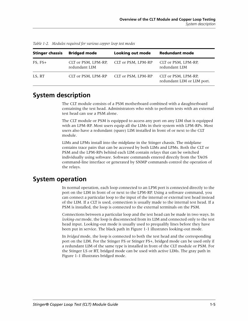
Table 1-2. Modules required for various copper loop test modes
Stinger chassis Bridged mode Looking out mode Redundant mode
FS, FS+ CLT or PSM, LPM-RP, redundant LIM
CLT or PSM, LPM-RP CLT or PSM, LPM-RP, redundant LIM
LS, RT CLT or PSM, LPM-RP CLT or PSM, LPM-RP CLT or PSM, LPM-RP, redundant LIM or LIM port.
Stinger® Copper Loop Test (CLT) Module Guide 1-5

Overview of the CLT Module and Copper Loop TestingSystem operation
Figure 1-1. CLT system
1-6 Stinger® Copper Loop Test (CLT) Module Guide

Overview of the CLT Module and Copper Loop TestingSupported tests
Supported testsThe CLT module supports the following copper loop tests:
■ Digital multimeter (DMM) tests
■ Line tests
■ Time-domain reflectometry (TDR) tests
■ Additional functions and commands
DMM testsDMM tests include measurement of dc and ac voltage, resistance, and capacitance. All tests can be performed between tip and ring, tip and ground, and ring and ground.
dc voltage
Measurement of dc voltage is used for unwanted (foreign) voltage detection. The measurement range is ±275 volts dc (Vdc).
ac voltage
Measurement of ac voltage is used for foreign voltage detection. The measurements up to 200 volts ac root mean square (Vac rms) can be made.
dc resistance
Measurement of dc resistance is used to detect shorts and leakage between tip and ring, tip and ground, and ring and ground. The measurement range is 1 ohm to 5 megohms (Mohms).
Capacitance
Capacitance measurement is primarily used for loop length estimation. This test report both the actual capacitance and the estimated length. Length estimation is calculated using the ANSI estimation factor of 83 nanofarads (nF) per mile and is reported in feet or meters. The measurement range is 1nF to 1 microfarad (µF).
Digital multimeter (DMM) dc delta measurement
This test measures loop resistance based on a dc Thevenin circuit. Tests are simultaneously made tip to ring (T-R), tip to shield (T-S), and ring to shield (R-S).
DMM ac delta measurement
This test measures loop resistance and capacitance based on an ac Thevenin circuit. Tests are simultaneously made tip to ring (T-R), tip to shield (T-S), and ring to shield (R-S).
DMM longitudinal balance
This test measures the longitudinal balance of the loop. This is a measure of how susceptible the line is to noise. Measurement of greater than 60dB indicate a good line.
Stinger® Copper Loop Test (CLT) Module Guide 1-7

Overview of the CLT Module and Copper Loop TestingSupported tests
DMM capacitance equivalent measurement
This test measures loop capacitance tip to ring (T-R), tip to shield (T-S), and ring to shield (R-S) simultaneously.
All-DMM measurement
This test makes tip to ring (T-R), tip to shield (T-S), and ring to shield (R-S) DMM measurements for a selected DMM function with one command.
Line tests
Line tests include noise measurements, insertion loss, coil detection, loop resistance, bridge-tap measurement, first coil location, and short-circuit location. The following sections describe available line tests.
Wideband noise
The wideband noise test detects interferers from sources such as other digital services, AM radio, or electrical equipment. The noise is measured using the Power Spectral Density (PSD) technique.
You test inactive lines after specifying the termination resistance to be placed on the received signal. Line termination can be set to either 100 or 135 ohms. A 100-ohm value is used for testing asymmetric digital subscriber (ADSL) lines, and 135 ohms is used for all other xDSL types.
Active lines are tested in a high-impedance mode that protects the live signal. When using high-impedance mode, you must set the termination mode to either Bridge 100 or Bridge 135. Bridge 100 is used for ADSL lines, and Bridge 135 is used for all other xDSL types. This setting allows the proper power levels to be computed from the received voltage.
Noise can be measured for four different frequency spectrums:
■ PSD—measures the noise in the full ADSL discrete multitone (DMT)/CAP spectrum of 22 kilohertz (kHz) to 1.6 megahertz (MHz). Test results are available as 371 pairs of frequency and amplitude data points over the frequency range. Amplitude is specified in decibels referred to 1 milliwatt per hertz. (dBm/Hz).
■ E—measures the aggregated noise in the ISDN Basic Rate Interface (BRI) spectrum at an impedance of 135 ohms. The frequency range is 1kHz to 50kHz. Test results are available as a single data point in dBm.
■ F—measures the aggregated noise in the high-bit-rate DSL (HDSL) spectrum at an impedance of 135 ohms. The frequency range is 5kHz to 245kHz. Test results are available as a single data point in dBm.
■ G—measures the aggregated noise in the ADSL spectrum at an impedance of 100 ohms. The frequency range is 20kHz to 1.1MHz. Test results are available as a single data point in dBm.
Impulse noise
The impulse noise measurement determines whether a loop is susceptible to any spurious impulse-noise spikes during a long period of time. The measurement duration can be anywhere from a few minutes to a few days. The test detects impulse
1-8 Stinger® Copper Loop Test (CLT) Module Guide

Overview of the CLT Module and Copper Loop TestingSupported tests
noise spikes on the signal and keeps a running count of the number of events over time.
Impulse events are divided in three categories. The Low count tallies the number of spikes between Threshold and Threshold + Delta. The Mid count reports the number of spikes with a level between Threshold + Delta and Threshold + 2Delta. The High count reports the number of spikes exceeding a level of Threshold + 2Delta.
Threshold can be specified over a range of 50dBm to 102dBm. Delta can be specified over a range of 2dB to 6dB.
Three other parameters are specified for the impulse test.
■ Max Count is the maximum number of impulse events that are counted during a single measurement. Max Count can be specified over a range of 1 to 9999.
■ Dead Time is the measurement delay after the unit detects the initial impulse. Dead Time starts when the noise spike is detect. The impulse noise test resumes measuring events after the Dead Time period has elapsed. This prevents the noise test from counting the same spike multiple times.
■ Timer specifies the duration of the impulse noise test. Timer can be specified over a range of 1 to 9999 minutes. You can specify a continuous test by setting the value of Timer to continuous.
Coil detection
The load coil detection test detects the presence and number of load coils in the loop. Up to five load coils can be detected. The distance to the first detected load coil can then be measured using a TDR test. After the first coil has been located and physically removed with the help of TDR testing, the coil detection test must be repeated to detect any additional coils.
First coil location
This test measures the distance to the first load coil in the loop.
Short-circuit location
This test measures the distance to a short circuit in the loop.
Bridge-tap measurement
This test detects the number of bridge taps, bridge-tap length, and location.
Detaptor test
This is a two ended test to detect the longest bridge tap in the loop. The result show the length of the longest tap.
Splitter detection
This test detects the presence of a splitter in the loop.
Insertion loss
The insertion loss test is a “paired” test requiring both the CLT module at the CO end and a test unit at the CPE end of the loop. The unit at the CPE end must be a SunSet
Stinger® Copper Loop Test (CLT) Module Guide 1-9

Overview of the CLT Module and Copper Loop TestingSupported tests
xDSL model SS160 copper loop test unit manufactured by Sunrise Telcom of San Jose, CA.
The insertion loss test measures the loss characteristics over a range of 13kHz to 1.6MHz. This covers the entire ADSL band. Test results are available as 371 pairs of frequency and signal loss data points over the frequency range. Frequency is specified in kilohertz, and loss is specified in decibels.
Signal-to-noise ratio (SNR)
The signal-to-noise ratio (SNR) test is also a paired test requiring both the CLT module at the CO end and a SunSet test unit at the CPE end of the loop. The test independently measures the best achievable signal-to-noise performance over the full range of frequencies used by DSL modems. The test results correlate to the SNR measurements used by DMT modems to adjust bit distribution and transmit power levels. It is particularly useful for identifying frequencies that have low noise margins.
The SNR test measures noise in the 22kHz-to-1.6Mhz spectrum. Test results are available as 367 pairs of frequency and SNR data points over the frequency range. Frequency is specified in kilohertz, and SNR is specified in decibels.
The SNR test depends on an insertion loss measurement. An insertion loss test must be performed first, immediately followed by the SNR test.
Loop resistance
The loop resistance test measures the resistance of the loop. You must short-circuit the loop at the CPE end to perform this measurement. You can short-circuit the loop manually or, if a SunSet test unit is available at the CPE end, you can enter commands to short-circuit the loop.
Loop resistance can be used to estimate loop length. Loop length is calculated based on cable gauge and temperature. The resistance measurement can also be used to verify that the circuit has an acceptable loop resistance.
You must specify the temperature before performing this test. Test results are reported in ohms, and estimated length in feet or centimeters. Length estimates are supplied for 22 American wire gauge (AWG), 24 AWG, and 26 AWG, or 0.6mm, 0.5mm, and 0.4mm wire sizes.
TDR testsTime-domain reflectometry (TDR) operates by sending a pulse of energy down the copper loop. It then measures any reflections or echoes that return to the receiver. These reflections are caused by faults or changes in impedance of the loop. By measuring the time it takes for the reflections to be received back, you can compute the distance to the fault.
For example, a load coil behaves like a large increase in impedance. Any major change in the loop’s insulation or fill material (like water in the cable) also causes a detectable reflection.
The TDR function of the CLT module can help you do the following:
■ Locate bridge taps, including the exact location and the length of the lateral.
■ Determine the presence and location of load coils.
■ Detect any other circuit faults, such as an open, short, or wet cable.
1-10 Stinger® Copper Loop Test (CLT) Module Guide

Overview of the CLT Module and Copper Loop TestingSupported tests
To perform these functions, you must use external software to analyze the data that the TDR function returns to you.
Before you can perform a TDR test, you must select the parameters for the test using the tdrset command.
Other functions and commandsOther functions and several maintenance commands are available from the test head. These include test tone sending and receiving, calibration, test head reset, and version reporting and download of test head software.
Send Tone function
Tones of a specified frequency and level can be sent from the test head. Frequency can be specified over a range of 10 to 1600kHz. Levels can be set over a range of -10 to +26dBm.
Send Control Tone function
This function sends control tones for ADSL and G.lite services. You can send quiet or restore tones.
Send Trace Tone function
This function sends trace tones tip to ring (T-R), tip to shield (T-S), and ring to shield (R-S). Power can be specified between -10dBm and 10dBm, with periods ranging from 1 minute to 120 minutes.
Stop Tone function
This function stops the transmission of tones.
Receive Tone function
The frequency and level of a tone on the loop can be measured. Frequency is reported in kilohertz, and level is reported in dBm. The level is measured for the highest power frequency.
Detect Ringer function
This test detects the presence of the ringer signal.
Detect ATU-R function
This test detects the presence of the ADSL transmission unit-remote (ATU-R) signal.
Voice detection
This test detects the presence of voice signals in the loop.
Voice signal detection
This test detects and measures various signals on the loop. The signal types include voice, DTMF, MF, tone, background noise, and signal-to-noise.
Stinger® Copper Loop Test (CLT) Module Guide 1-11

Overview of the CLT Module and Copper Loop TestingHow to perform tests
Send voice signal
This test sends voice and tone signals in various modes. The modes include tone, three tone, sweep, DTMF, and female voice.
Dial tone testing and analysis
The function can draw, break, and analyze the subscriber dial tone.
Splitter bypass
This function controls the bypass mode on programmable splitters. Currently the Intelligent POTS Splitter (iPOTS) manufactured by mPhase Technologies is supported.
Responder mode
This function sets the CLT module to responder mode. In responder mode, the CLT module can be used with a Sunset DSL test set at the CPE end of the loop to perform two-ended testing. Two-ended tests include insertion loss, loop resistance, and signal-to-noise ratio measurements.
Calibrating the test head circuitry
The calibration command internally calibrates the measurement circuitry of the test head. Lucent recommends that you perform calibration at the following times:
■ Every 30 operation days
■ After you enter the reset command
Resetting the hardware circuitry of the test head
The reset command restarts the hardware circuitry of the test head.
Test head software version
The version command reports the software version of the test head.
Upgrading test head software
The download command upgrades the test head software.
Caution Use the download command only if you are qualified Lucent service personnel or are working under their direction.
How to perform tests Testing can be initiated by means of either the TAOS command-line interface or SNMP. For more information, see Chapter 2, “Copper Loop Testing through the Command-Line Interface” or Chapter 3, “Copper Loop Testing through SNMP.”
Test results are obtained through the TAOS command-line interface, SNMP, or the TL1 interface.
1-12 Stinger® Copper Loop Test (CLT) Module Guide

Overview of the CLT Module and Copper Loop TestingHow to perform tests
To run a test, you perform the following tasks:
1 Using TAOS command-line interface commands or SNMP, select the copper loop to be tested and activate the test head. (If a PSM and an external test head are used for testing, only this step is needed.)
2 Enter the commands and parameters or SNMP objects necessary to select and characterize the desired test.
3 After waiting for the test to finish, access the resulting data using the command-line interface or SNMP, and pass it to external software for analysis.
Stinger® Copper Loop Test (CLT) Module Guide 1-13


2Copper Loop Testing through the Command-Line Interface
The TAOS command-line interface (CLI) can be used to set the parameters for, initiate, and obtain the results of any available copper loop test (CLT).
Using the command-line interface You perform testing either by entering clt commands or by setting parameters in various clt profiles.
Performing tests using clt commands
Tests are performed with clt commands as follows:
1 Select the loop with the cltactivate command.
See “Enabling test access with the cltactivate command” on page 2-2.
2 Select the test and its parameters with the cltcmd command.
See “Selecting tests using the cltcmd command” on page 2-10.
The results of the tests are displayed on your terminal.
Performing tests using clt-ms-access profile
Perform tests by setting the parameters of clt profiles as follows:
1 Select the loop by using the set command to set the appropriate parameters in the clt-ms-access profile.
When all the parameters have been set, use the write command to store the parameters and activate loop access. See “Enabling test access through the clt-ms-access profile” on page 2-5.
2 Set the parameters for the desired test by using the set command.
When all the parameters have been set use the write command to store the values. See “Selecting tests using the clt-command profile” on page 2-24.
Using the command-line interface . . . . . . . . . . . . . . . . . . . . . . . . . . . . . . . . . . . . 2-1
Activating tester and copper loop access . . . . . . . . . . . . . . . . . . . . . . . . . . . . . . . 2-2
Selecting a test . . . . . . . . . . . . . . . . . . . . . . . . . . . . . . . . . . . . . . . . . . . . . . . . . . 2-10
Determining test results . . . . . . . . . . . . . . . . . . . . . . . . . . . . . . . . . . . . . . . . . . . 2-33
Stinger® Copper Loop Test (CLT) Module Guide 2-1
Copper Loop Testing through the Command-Line InterfaceActivating tester and copper loop access
3 Use the set command to set the test-operation parameter to select the desired test. Use the write command to store the value and start the selected test. See “Selecting tests using the clt-command profile” on page 2-24.
4 Monitor the value of the test-result-status parameter in the clt-result profile to determine when the test is completed.
See “Determining test results” on page 2-33.
5 Use the list command to list the clt-result profile and view the test results.
Activating tester and copper loop accessTo activate tester access, connect the copper loop to an internal test head or to an external test terminal. Perform this step by using the cltactivate command or by setting parameters in the clt-ms-access profile. If you are using a path selector module (PSM) and an external test head, only this step needed.
Enabling test access with the cltactivate commandFrom the command line, you can enter the cltactivate and cltdeactivate commands.
Using the cltactivate command
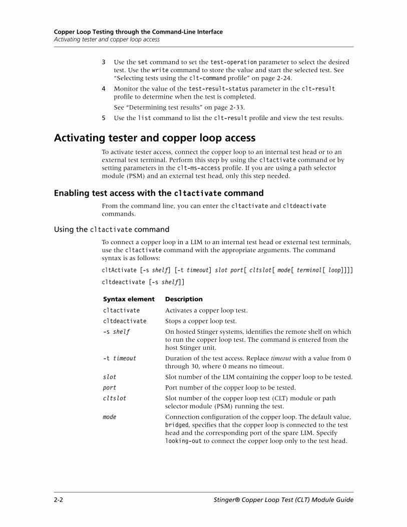
To connect a copper loop in a LIM to an internal test head or external test terminals, use the cltactivate command with the appropriate arguments. The command syntax is as follows:
cltActivate [-s shelf] [-t timeout] slot port[ cltslot[ mode[ terminal[ loop]]]]
cltdeactivate [-s shelf]]
Syntax element Description
cltactivate Activates a copper loop test.
cltdeactivate Stops a copper loop test.
-s shelf On hosted Stinger systems, identifies the remote shelf on which to run the copper loop test. The command is entered from the host Stinger unit.
-t timeout Duration of the test access. Replace timeout with a value from 0 through 30, where 0 means no timeout.
slot Slot number of the LIM containing the copper loop to be tested.
port Port number of the copper loop to be tested.
cltslot Slot number of the copper loop test (CLT) module or path selector module (PSM) running the test.
mode Connection configuration of the copper loop. The default value, bridged, specifies that the copper loop is connected to the test head and the corresponding port of the spare LIM. Specify looking-out to connect the copper loop only to the test head.
2-2 Stinger® Copper Loop Test (CLT) Module Guide

Copper Loop Testing through the Command-Line InterfaceActivating tester and copper loop access
On a standalone system, the following sample command activates the copper loop on slot two, port 32. The CLT module is installed in slot 15:
admin> cltactivate 2 32 15 bridged internal LOG notice, Shelf 1, Slot 8, Time: 11:58:49-- LIM 15 IF 32 ACTIVATED as spare for IF 2
The following sample command, entered on the host Stinger system, activates a test locally. The cltdeactivate command stops the test.
admin> cltactivate 2 2 2 looking-out external
admin> LOG notice, Shelf 1, Controller-2, Time: 13:38:10-- Copper loop access activated at shelf 1
admin> cltdeactivateLOG notice, Shelf 1, Controller-2, Time: 13:38:22-- Copper loop access idle at shelf 1
The following sample command, entered from a host Stinger unit, activates a test on a remote shelf with the shelf ID of 2.
admin> cltactivate -s 2 1 1 1 looking-out external
admin> LOG notice, Shelf 2, Controller-1, Time: 13:39:16-- Copper loop access activated at shelf 2
The following command, entered from the host Stinger unit, stops the preceding test:
admin> cltdeactivate -s 2 LOG notice, Shelf 2, Controller-1, Time: 13:39:32-- Copper loop access idle at shelf 2
The following sample command, entered from a remote shelf, activates a copper loop test locally:
admin> cltactivate 1 1 1 looking-out external
terminal Connection point of the copper loop. Specify one of the following values:
■ internal-tester-terminal—Copper loop is connected to the internal test head of the CLT module. If you specify no argument, the system takes this default value.
■ external-tester-terminal—Copper loop is connected to the external test terminals of the CLT module or PSM.
■ auxiliary-tester-terminal—Copper loop is connected to the auxiliary test terminals of the CLT module or PSM.
loop Copper loop number of the T1 or E1 port. This parameter applies only to copper loops connected to T1 or E1 LIMs, and is ignored for all other LIMs.
1—Transmit copper loop.
2—Receive copper loop.
Syntax element Description
Stinger® Copper Loop Test (CLT) Module Guide 2-3

Copper Loop Testing through the Command-Line InterfaceActivating tester and copper loop access
admin> rearslotshow
Shelf 2 (slave) : Slot Slot ID [ 1 ] ee 48 port LPM with splitter for CR/LS/RT [ 2 ] 98 LSRT 48 port Path Selector Module ( PSM ) [ 3 ] 0 Empty ( IRM, LPM )
Midplane sparing bus usage :
7 6 5 4 3 2109 8765 4321 0987 6543 2109 8765 4321 0987 .... .... .... .... .... .... .... .... ....
3 2 1 6543 2109 8765 4321 0987 6543 2109 8765 4321 .... .... .... .... .... .... .... .... ....
Test Bus usage : in use
The following command stops the preceding test. Entering the rearslotshow command confirms that access has been deactivated.
admin> cltdeactivate
admin> rearslotshowShelf 2 (slave) : Slot Slot ID [ 1 ] ee 48 port LPM with splitter for CR/LS/RT [ 2 ] 98 LSRT 48 port Path Selector Module ( PSM ) [ 3 ] 0 Empty ( IRM, LPM )
Midplane sparing bus usage :
7 6 5 4 3 2109 8765 4321 0987 6543 2109 8765 4321 0987 .... .... .... .... .... .... .... .... ....
3 2 1 6543 2109 8765 4321 0987 6543 2109 8765 4321 .... .... .... .... .... .... .... .... ....
Test Bus usage : not in use
Using the CLT module as a test head for an external loop
You use the cltactivate external-loop command to enable a Stinger unit with a CLT module to test copper loops connected to other Stinger units that are equipped with only a path selector module (PSM). The command syntax is as follows:
cltActivate [-s shelf] [-t timeout] external-loop
2-4 Stinger® Copper Loop Test (CLT) Module Guide

Copper Loop Testing through the Command-Line InterfaceActivating tester and copper loop access
The following example sets the CLT module as a test head for an external loop. The CLT slot is detected automatically, and the access mode is set to looking-out. For example:
admin> cltactivate external-loop
Deactivating the connection between a copper loop and a test head
You can manually deactivate the connection between a copper loop and an internal test head or external test terminals by using the cltdeactivate command. Alternatively, when you can also set a timeout value when you activate copper loop access. See “Specifying a timeout value for copper loop access” on page 2-8.
To stop a test locally, enter this command without any parameters. For example:
admin> cltdeactivate LOG notice, Shelf 1, Slot 8, Time: 12:07:51-- LIM 15 IF 32 DEACTIVATED as spare for IF 2
Enabling test access through the clt-ms-access profileYou can also activate tester access by means of the clt-ms-access profile. Following are the clt-ms-access profile parameters with their default values.
[in CLT-MS-ACCESS/any-shelf (new)]cltm-shelf* = any-shelfcltm-slot = slot-16access-slot = slot-16access-port = 1access-loop = 1access-mode = looking-outaccess-terminal = internal-tester-terminalactivate-access = noaccess-timeout = 0
Parameter Specifies
cltm-slot Slot number where the CLT module or PSM is installed.
access-slot Slot number of the LIM containing the copper loop to be tested.
access-port Port number of the copper loop to be tested.
access-loop Copper loop number of the T1 or E1 port. This parameter applies only to copper loops connected to T1 or E1 LIMs and is ignored for all other LIMs. Specify one of the following values:
1—Transmit copper loop.
2—Receive copper loop.
Stinger® Copper Loop Test (CLT) Module Guide 2-5

Copper Loop Testing through the Command-Line InterfaceActivating tester and copper loop access
Example using the clt-ms-access profile
The following example shows how to activate copper loop access for port 32 of the the LIM installed in slot 2, in bridged mode. The CLT module is in slot 15.
admin> set cltm-slot = 15
admin> set access-slot = 2
admin> set access-port = 32
admin> set access-mode = bridged
admin> set activate-access = yes
admin> write
LOG notice, Shelf 1, Slot 8, Time: 15:54:08-- LIM 15 IF 32 ACTIVATED as spare for IF 2
access-mode Connection configuration of the copper loop. Valid values are:
■ bridged—Copper loop is connected to the test head and the corresponding port of the spare LIM.
■ looking-out (the default)—Copper loop is connected only to the test head.
access-terminal Connection point of the copper loop. Valid values are:
■ internal-tester-terminal (the default)—Copper loop is connected to the internal test head of the CLT module.
■ external-tester-terminal—Copper loop is connected to the external test terminals of the CLT module or PSM.
■ auxiliary-tester-terminal—Copper loop is connected to the auxiliary test terminals of the CLT module or PSM.
■ external-loop—Internal test head of CLT module is connected to the TEST PAIR connector of the CLT module.
activate-access Activate tester connection to the copper loop. Valid values are:
■ yes—Copper loop is connected as specified.
■ no—Copper loop is disconnected from test head or test terminals.
■ extend—Extend CLT access period beyond the specified timeout value.
access-timeout Duration of copper loop access. Specify a value 0 through 30 minutes. See “Specifying a timeout value for copper loop access” on page 2-8 for more information.
Parameter Specifies
2-6 Stinger® Copper Loop Test (CLT) Module Guide

Copper Loop Testing through the Command-Line InterfaceActivating tester and copper loop access
Enabling loop testing with one CLT module and multiple Stinger units
Several PSM-equipped Stinger units can be served by one Stinger unit equipped with a CLT module. To use this method, connect the tip, ring, and ground connections of the TEST PAIR connectors on the PSMs to the TEST PAIR connector on the CLT module, using either a daisy-chain or star configuration.
Then, using the cltactivate command or by modifying the clt-ms-access profile for the appropriate Stinger unit, proceed as follows:
1 Select the loop to be tested on the appropriate Stinger unit and set the access terminal on that unit to external-tester-terminal.
2 Set the access terminal for the Stinger unit containing the CLT module to external-loop.
Sample two-unit configuration
A system is set up with two Stinger units. Stinger 1 is configured with a PSM in slot 12 and ADSL LIMs in slots 1 through 7. Stinger 2 is equipped with a CLT module in slot 16. You want to perform loop tests on the loop connected to port 7 of the ADSL LIM in slot 2 of Stinger 1. Proceed as follows.
Using the cltactivate command
1 Connect tip, ring, and ground connection of the TEST PAIR connector on the PSM in Stinger 1 to the respective tip, ring, and ground connections of the TEST PAIR connector on the CLT module in Stinger 2.
2 Enter the cltactivate command for Stinger 1 as follows:
admin> cltactivate 2 7 12 looking-out external-tester-terminal
3 Enter the cltactivate command for Stinger 2 as follows:
admin> cltactivate external-loop
4 Proceed with the desired test selection and result collection commands on Stinger 2.
Using the clt-ms-access profile
1 Connect the tip, ring, and ground connection of the TEST PAIR connector on the PSM in Stinger 1 to the respective tip, ring, and ground connections of the TEST PAIR connector on the CLT module in Stinger 2.
2 Configure the clt-ms-access profile for Stinger 1. For example:
admin> read clt-ms-access clt-ms-access read
admin> set cltm-slot = 12
admin> set access-slot = 2
admin> set access-port = 7
admin> set access-terminal = external-tester-terminal
admin> set activate-access = yes
admin> write clt-ms-access written
Stinger® Copper Loop Test (CLT) Module Guide 2-7

Copper Loop Testing through the Command-Line InterfaceActivating tester and copper loop access
3 Configure the clt-ms-access profile for Stinger 2 as follows:
admin> read clt-ms-access clt-ms-access read
admin> set access-terminal = external-loop
admin> set activate-access = yes
admin> write
4 Configure the clt-command and clt-results profiles for the desired tests on Stinger 2.
Specifying a timeout value for copper loop accessYou can specify a timeout value for copper loop access using the cltactivate command or the clt-ms-access profile. Copper loop access is deactivated automatically when you specify a timeout value.
Using the cltactivate command
To specify a timeout value for a copper loop access, use the cltactivate command with the -t option. The -t timeout argument indicates the duration of the test in minutes. Replace timeout with a value from 0 through 30, where 0 means no timeout.
For example, on a hosted system, the following sample command entered from a host activates copper loop access for a duration of 2 minutes on slot 5, port 1. The CLT module is in slot 5.
admin> cltactivate -s 1 -t 2 5 1 5admin> LOG notice, Shelf 1, Controller-1, Time: 10:08:47-- Copper loop access activated at shelf 1
When two minutes have elapsed, the system automatically deactivates copper loop access, and generates the following log message:LOG notice, Shelf 1, Controller-1, Time: 10:10:47-- Copper loop access idle at shelf 1
Using the clt-ms-access profile to set a timeout value
To set a timeout value for a copper loop test, set the access-timeout parameter in the clt-ms-access profile to a value from 0 through 30. For example, the following command sets the timeout value to 5 minutes:
admin> set access-timeout = 5
Extending the duration of copper loop test accessYou can extend the duration of an activated copper loop test access by using the cltextend command or by setting the active-access parameter in the clt-ms-access profile. When you extend the duration of a copper loop access, the new test period begins when you make the change and ends after the timeout value specified has elapsed.
2-8 Stinger® Copper Loop Test (CLT) Module Guide

Copper Loop Testing through the Command-Line InterfaceViewing copper loop access results
Using the cltextend command
The cltextend command extends the duration of an activated test by the timeout period specified. The syntax of the cltextend command is as follows:
cltextend [-s shelf]
On hosted systems, when you use the -s shelf argument, you must enter the command from the controller on the host shelf.
The following sample command activates copper loop access on shelf 1 for 4 minutes:
admin> cltactivate -t 4 5 1 5LOG notice, Shelf 1, Controller-1, Time: 10:12:42-- Copper loop access activated at shelf 1
When you enter the cltextend command at 10:13:36, the duration of the test access extends by four minutes.
admin> cltextendLOG notice, Shelf 1, Controller-1, Time: 10:13:36-- Copper loop access extended at shelf 1
After four minutes, the system deactivates test access and generates the following log message:
LOG notice, Shelf 1, Controller-1, Time: 10:17:36-- Copper loop access idle at shelf 1
If you enter the cltextend command when copper loop access is inactive, the system generates the following message:
Copper loop access should be activated first
Using the clt-ms-access profile
To extend an activate copper loop test access beyond a specified timeout value, set the activate-access parameter in the clt-ms-access profile to extend. For example:
admin> set activate-access = extend
Note that after you have written the profile, the setting of the activate-access parameter reverts to yes.
Viewing copper loop access resultsThe clt-ms-access-stat profile displays the status of the CLT access. Following is a sample listing of the clt-ms-access-stat profile, followed by parameter descriptions:
[in CLT-MS-ACCESS-STAT/shelf-1]cltm-shelf* = shelf-1access-result = idleaccess-start-time = { 0 0 0 }access-start-date = { Monday January 1990 1 }access-end-time = { 0 0 0 }access-end-date = { Monday January 1990 1 }access-change-reason = deactivation
Stinger® Copper Loop Test (CLT) Module Guide 2-9

Copper Loop Testing through the Command-Line InterfaceSelecting a test
Selecting a testNext, specify the copper loop test and specify its parameters. You can do so by using the cltcmd command or the clt-command profile.
Selecting tests using the cltcmd commandFrom the command line, enter the cltcmd command and supply the test name and any relevant parameters. Following is the cltcmd syntax and summary of test options.
cltcmd test [test_option]
Parameter Specifies
access-result Result of activating the cooper loop access. Values can be:
■ idle—Loop access is not yet ready.
■ access-activated—Access enabled.
■ resource-busy—Access failed. The resource to enable CLT access is in use.
access-start-time/ access-start-date
Time and date that copper loop access was activated. If copper loop access is inactivate, the reported value is 0:0:0, 1/1/1990. The settings for these parameters do not change for an existing test when you extend CLT access.
access-end-time/ access-end-date
End time and date of copper loop access. If access is not activated, the default value of this parameter is 0:0:0, 1/1/1990. If no timeout value, the maximum system time is specified, the default is used. This value changes accordingly when you extend test access.
access-change-reason Reason for the change in this profile. Possible values are:
■ unknown—Unknown reason or the if the profile has not changed since it was created.
■ activation—Copper loop access was activated.
■ deactivation—Copper loop access was deactivated.
■ extension—Copper loop duration was extended.
■ failure—Copper loop access failed.
Test option Specifies
The copper loop test, test setup, or maintenance action to execute.
bgns Run a background noise test. You must run the calib command before performing this test.
btap Detect the number of bridge taps, their lengths, and locations.
calib Calibrate the measurement circuitry of the test head internally. Use the cltcmd calib command after every 30 days of CLT module use and after entering the cltcmd reset command.
cldet Run a coil detection test.
cpemdm Detect an ATU-R signal.
2-10 Stinger® Copper Loop Test (CLT) Module Guide

Copper Loop Testing through the Command-Line InterfaceSelecting a test
ctonesnd Send a control tone of a specified type and service for DSL modems.
detaptor Run a detaptor test.
dnld Download software upgrades to the test head.
dmm Run a digital multimeter (DMM) measurement test.
dmmacd Run a DMM ac delta measurement test.
dmmall Run the selected DMM test, tip to ring (T-R), tip to shield (T-S), and ring to shield (R-S) simultaneously.
dmmcap Run a DMM capacitance equivalent test.
dmmdcd Run a DMM dc delta measurement test.
dmmlbal Run a DMM longitudinal balance test.
dta Draw, break and analyze subscriber dial tone.
fclloc Measure the distance to the first load coil.
impread Read the impulse noise test result.
impstart Start the impulse noise test.
impstop Stop the impulse noise test.
inls Run an insertion loss test. This test requires the presence of an additional test set at the CPE end of the loop.
lpres Run a loop resistance test. The CPE end must be shorted or connected to an xDSL test set.
measvoice Detect voice signal or narrow band tone.
reset Reset the test head module.
rngr Detect the presence of a ringer.
setbypass Place an mPhase iPOTS splitter in bypass mode.
setresp Place the CLT module in responder mode.
shortloc Measure the distance to a short circuit in the loop.
signs Run a signal-to-noise test. This test requires the presence of an additional test set at the CPE end of the loop.
sndvoice Send voice signal.
splitter Detect the presence of a splitter in the loop circuit.
tdr Run a TDR test. You must run the tdrset command before running this test.
tdrset Sets time-domain reflectometry (TDR) test parameters.
tonercv Measure the frequency (kilohertz) and level (dBm) of tones received on the copper loop.
tonesnd Send a tone of the specified frequency (kilohertz) and level (dBm) from the test head.
tstop Stop the sending of tones.
ttonesnd Send a trace tone of 577.5Hz over selected pair at a specified power and duration.
Test option Specifies
Stinger® Copper Loop Test (CLT) Module Guide 2-11

Copper Loop Testing through the Command-Line InterfaceSelecting a test
Running a background noise test (cltcmd bgns)
To run a background noise test, use the cltcmd bgns command. The command syntax is as follows:
cltcmd bgns [psd|e|f|g] [term100|term135|bridge100|bridge135]
You must calibrate the test head before running this test, using the cltcmd calib command.
For example:
admin> cltcmd bgns e term135
Detecting a bridgetap, bridge-tap length, and location (cltcmd btap)
To detect a single bridge-tap, its length, and location, use the cltcmd bgns command. the command syntax is as follows:
cltcmd btap start length
vers Display the version of the hardware and software running on the internal test head.
voicedet Detect the presence of voice signals on the loop.
Test option Specifies
Option Description
psd Measures power spectral density in a 22kHz-to-1.6MHz range.
e Reports one noise value at 135-ohm impedance for a 1kHz-to-50kHz range. Used for ISDN qualification.
f Reports one value for a 5kHz-to-245kHz range. Used for HDSL qualification.
g Reports one noise value at 100-ohm impedance for a 10kHz-to-1.1Mhz range. Used for ADSL qualification
term100 Places a 100-ohm termination on the received signal.
term135 Places a 135-ohm termination on the received signal.
bridge100 Puts the receiver in high-impedence mode, and calculates the noise signal based on 100-ohm impedence.
bridge135 Puts the receiver in high-impedence mode, and calculates the noise signal based on 135-ohm impedence.
Option Description
start Starting location for bridge-tap search.
Range is 15 to 20000 feet if TDR units is set to ENGLISH.
Range is 5 to 6097 meters if TDR units is set to METRIC.
length Loop length for bridge tap search.
Range is 100 to 20000 feet if TDR units is set to ENGLISH.
Range is 32 to 6097 meters if TDR units is set to METRIC.
2-12 Stinger® Copper Loop Test (CLT) Module Guide

Copper Loop Testing through the Command-Line InterfaceSelecting a test
For example:
admin> cltcmd btap 100 1000 Number of bridge taps = 0,Loop length = 284 CLT operation completed.
Detecting an ATU-R signal (cltcmd cpemdm)
To detect an ATU-R signal, use the cltcmd cpemdm command. This command is applicable only to ADSL LIMs. There are no other options for this command. For example:
admin> cltcmd cpemdm CPE detected: NO CLT operation completed.
Sending an xDSL control tone (cltcmd ctonesnd)
To send an xDSL control tone, use the cltcmd ctonsnd command. Command syntax is as follows:
cltcmd ctonesnd adsl | glite quiet | restore
For example:
admin> cltcmd ctonesnd adsl quiet CLT operation completed.
Detecting the longest bridge tap in a copper loop (cltcmd detaptor)
To run a two-ended test to detect the longest bridge tap in the copper loop, us the cltcmd detaptor command. Command syntax is as follows:
cltcmd detaptor [metric|english] Vp ( 0 - 99 V)
For example:
admin> cltcmd detaptor metric 50 admin> No. of taps detected are 2 and tap length is 20000 in cm CLT operation completed.
Option Description
adsl Set for ADSL service.
glite Set for G.lite service.
quiet Send quiet tone.
restore Send restore tone.
Option Description
metric Set units for length to metric.
english Set units for length to English.
vp Set peak voltage. Range is from 0 to 99 volts
Stinger® Copper Loop Test (CLT) Module Guide 2-13

Copper Loop Testing through the Command-Line InterfaceSelecting a test
Running a digital multimeter (DMM) measurement (cltcmd dmm)
To run a digital multimeter (DMM) measurement test, use the cltcmd dmm command using the following syntax:
cltcmd dmm [ohm|dcv|acv|cap] [t-r|t-s|r-s]
For example:
admin> cltcmd dmm dcv t-r
Running a DMM ac delta test (cltcmd dmmacd)
To run a DMM ac delta test, use the cltcmd dmmacd command using the following syntax. This command is applicable only to the CLTE module.
cltcmd dmmacd time voltage frequency
For example:
admin> cltcmd dmmacd 2 12 1200 admin> Capacitance (T-R) 368 (T-S) 210 (R-S) 197 pF Resistance (T-R) 14534 (T-S) 188872 (R-S) 191260 Ohm
Running selected DMM test (cltcmd dmmall)
To run a selected DMM test on tip to ring (T-R), tip to shield (T-S), and ring to shield (R-S) use the cltcmd dmmall command using the following syntax:
Option Description
ohm Resistance test
dcv dc voltage test
acv ac voltage test
cap Capacitance test
t-r Measure between tip and ring.
t-s Measure between tip and sleeve (ground).
r-s Measure between ring and sleeve (ground).
Option Description
time Settling time. Specify 0 to 5 tenths (.1) of seconds.
voltage Test voltage. Specify 1 to 24 volts RMS.
frequency Output frequency. Specify output frequency from 20Hz to 2000Hz.
2-14 Stinger® Copper Loop Test (CLT) Module Guide

Copper Loop Testing through the Command-Line InterfaceSelecting a test
cltcmd dmmall type time input impedance
For example:
admin> cltcmd dmmall ohm 1 100Resistance (T-R) 123 (T-S) 74 (R-S) 340 OhmCLT operation completed.
Running a DMM capacitance equivalent measurement (cltcmd dmmcap)
To run a DMM capacitance equivalent measurement, use the cltcmd dmmcap command. Specify a duration from between 0 to 5 tenths (0.1) of a second. For example:
admin > cltcmd dmmcap 1Capacitance (T-R) 150, (T-S) 64, (R-S) 64 pFCLT operation completed.
Running a DMM dc delta measurement (cltcmd dmmdcd)
To run a DMM dc delta measurement, use the cltcmd dmmdcd command. Command syntax is as follows:
cltcmd dmmdcd time voltage output impedance
For example:
admin> cltcmd dmmdcd 1 10 10Resistance (T-R) 123 (T-S) 123 (R-S) 123 OhmDC Voltage (T-S) 76 (R-S) 48 mVCLT operation completed.
Option Description
type Specify one of the following tests:
■ ohm—Resistance test
■ dcv—dc voltage test
■ acv—ac voltage test
time Specify a duration of between 0 to 5 tenths (0.1) second.
input impedance Specify an input impedance of between 100Kohm or 1000Kohm.
Option Description
time 0 to 5 tenths (0.1) second
voltage -230 to 230 V
output impedance 10 to 1000 Kohm
Stinger® Copper Loop Test (CLT) Module Guide 2-15

Copper Loop Testing through the Command-Line InterfaceSelecting a test
Running a DMM longitudinal balance test (cltcmd dmmlbal)
To run a DMM longitudinal balance test, use the cltcmd dmmlbal command. This test is applicable to a Command syntax is as follows:
cltcmd dmmlbal time voltage frequency
For example:
admin> cltcmd dmmlbal 3 12 1900 admin> Longitudinal Balance 29 in db CLT operation completed
Drawing, breaking, and analyzing subscriber dial tone (cltcmd dta)
To draw, break, and analyze subscriber dial tone, use the cltcmd dta command. This command is applicable only to a CLTE module. Command syntax is as follows:
cltcmd dta [term|dtmf]
For example:
admin> cltcmd dta dtmf admin> The Result Obtained is DTA: Cannot Draw CLT operation completed.
Measuring the distance to the first load coil in a copper loop (cltcmd fclloc)
To measure the distance to the first load coil in a copper loop, use the cltcmd fclloc command. Command syntax is as follows:
cltcmd fclloc metric|english gauge
Option Description
time Settling time. Specify 0 to 5 tenths (.1) of seconds.
voltage Test voltage. Specify 1 to 24 volts RMS.
frequency Output frequency. Specify output frequency from 20Hz to 2000Hz.
Option Description
term Remove bridge to create dial tone break.
dtmf Use DTMF tone to create dial tone break.
Option Description
metric Uses metric units for test parameters and results.
english Uses English units for test parameters and results.
gauge Gauge of the cable in the loop, one of the following
■ In English units, 22 AWG, 24 AWG, or 26 AWG
■ In metric units, 4, 5, or 6 tenths of a millimeter
2-16 Stinger® Copper Loop Test (CLT) Module Guide

Copper Loop Testing through the Command-Line InterfaceSelecting a test
For example, to measure the distance in centimeters to the first load coil in a 0.04mm loop, enter the following command:
admin> cltcmd fclloc metric 4 admin> First Coil Location: 9750 cm. CLT operation completed.
Running an impulse noise test
To starts the impulse noise test, use the cltcmd impstart command.
cltcmd impstart threshold delta max-count dead-time timer
For example:
admin> cltcmd impstart 70 4 5000 500 20
The following command stops the impulse noise test:
admin> cltcmd impstop CLT operation completed.
To read and display the impulse noise test result, use the cltcmd impread command. For example:
admin> cltcmd impread
Running an insertion loss test (cltcmd inls)
To run an insertion loss test, enter cltcmd inls command. An additional test set at the CPE end of the loop must be present.
For example:
admin> cltcmd inls admin> Frequency 30 Khz, Loss 200 0.01dBm Indicates out of range result CLT operation completed.
Option Description
threshold Threshold value of the smallest noise spike detected, a value within the range 50 through 100dBm.
delta Number of decibels referred to 1mW (dBm) above the threshold—to measure for noise spike detection, a value within the range 2 through 6dBm.
max-count Maximum number of impulse events to be counted during a single measurement, a value from 1 through 9999.
dead-time Measurement delay after the unit detects the initial impulse, a value from 10 through 250 tenths (0.1) of a millisecond (ms).
time Duration of noise measurement, a value from 1 through 9999 minutes.
Stinger® Copper Loop Test (CLT) Module Guide 2-17

Copper Loop Testing through the Command-Line InterfaceSelecting a test
Running a loop resistance test (cltcmd lpres)
To run a loop resistance test, use the cltcmd lpres command. This test requires that the loop be shorted at the CPE end of the loop.
cltcmd lpres [english|metric] temp
Detecting voice signal or narrow band tone (cltcmd measvoice)
To detect and measures voice, tone or signal noise ratio on the copper loop, use the cltcmd measvoice command. This command is applicable only to a CLTE module.
You use the following command to detect voice signals, DTMF tones, or MF tones.
cltcmd measvoice auto|dtmf|mf p
For example:
admin> cltcmd measvoice auto 1 Voice signal not detected CLT operation completed.
You use the following command syntax to run a background noise test:
cltcmd measvoice bgns cmsg|3kflat
Option Description
english Use English units for test parameters and results.
metric Use metric units for test parameters and results.
temp Temperature of the loop, a value within either of the following ranges:
■ In English units, from 0 through 200 degrees F
■ In metric units, from -178 through 933 degrees C, in tenths (0.1) of a degree
Option Specifies
auto Determines if voice signal is present on the loop.
dtmf Determines if if DTMF tones exist on the loop.
mf Determines if if MF tones exist on the loop.
p Detection period between 1 and 20 seconds.
Option Specifies
bgns Background noise test.
cmsg C-message filter for noise test.
3kflat 3-Kflat filter for noise test.
2-18 Stinger® Copper Loop Test (CLT) Module Guide

Copper Loop Testing through the Command-Line InterfaceSelecting a test
You use the following command syntax to detect a single tone or to measure a signal-to-noise levels using a C-notch filter:
cltcmd measvoice tone|sgns
Detecting the presence of a ringer (cltcmd rngr)
To detect the presence of a ringer, enter the cltcmd rngr command. For example:
admin> cltcmd rngrRinger detected: NOCLT operation completed.
Toggling an mPhase iPOTS splitter (cltcmd setbypass)
To toggle an mPhase iPOTS splitter in and out of bypass mode, enter the cltcmd setbypass command. For example:
admin > cltcmd setbypass CLT operation completed
Successive instances of this command toggle the splitter bypass mode from off to on and back.
Putting the CLT module in responder mode (cltcmd setresp)
To put the CLT module in responder mode, enter the cltcmd setresp command. The command syntax is as follows:
cltcmd setresp on|off time
For example:
admin > setresp on 15
Option Description
tone Tone mode—detects a single tone.
sgns Signal-to-noise mode. Measures signal-to-noise levels using a C-notch filter.
Option Specifies
on CLT responder mode is on.
off CLT responder mode is off.
time Period that the CLT module is in duration mode. Specify a value from 1 through 999 minutes. This setting is valid only when responder mode is on.
Stinger® Copper Loop Test (CLT) Module Guide 2-19

Copper Loop Testing through the Command-Line InterfaceSelecting a test
Measuring the distance to a short circuit (cltcmd shortloc)
Use the following command syntax to measure the distance to a short circuit in a copper loop:
cltcmd shortloc metric|english gauge detect|nodetect
For example, to detect a short circuit in a 24AWG copper loop and measure the distance to it in feet, enter the following command:
admin> cltcmd shortloc english 24 detect admin> Short Location: 134117 0.01 ft. CLT operation completed.
Running a signal-to-noise test (cltcmd signs)
To run a signal-to-noise test, enter the cltcmd signs command. This test requires the presence of an additional test set at the CPE end of the copper loop.
Sending voice or tone signals on the copper loop (cltcmd sndvoice)
To send actual voice or tone signals on the copper loop in various modes, use the cltcmd sndvoice command. This command is applicable only to the CLTE module. Possible modes are listed below. Following is the syntax information for each mode.
For tone mode: cltcmd sndvoice tone frequency level time
For example:
admin> cltcmd sndvoice tone 450 2 1 admin>
Option Specifies
metric Use metric units for test parameters and results.
english Use English units for test parameters and results.
gauge Gauge of the cable in the loop, one of the following
■ In English units, 22 AWG, 24 AWG, or 26 AWG
■ In metric units, 4, 5, or 6 tenths of a millimeter
detect Detect the short with a DMM test and then measures its location.
nodetect Measure the distance to a short circuit without a DMM test.
Option Specifies
tone Single tone mode.
frequency Tone frequency. Specify a frequency from 300Hz to 4000Hz.
level Tone level. Specify a value from -30dBm to 10dBm.
time Total duration of the tone. Specify a value between of 1 through 120 minutes.
2-20 Stinger® Copper Loop Test (CLT) Module Guide

Copper Loop Testing through the Command-Line InterfaceSelecting a test
For 3 tone mode: cltcmd sndvoice 3-tone level period time
For sweep mode: cltcmd sndvoice sweep start end increment level period
For send voice mode: cltcmd sndvoice dtmf|mf string
For digit mode: cltcmd sndvoice digit string
Detecting the presence of a splitter (cltcmd splitter)
To detect the presence of a splitter in the copper loop circuit, enter the cltcmd splitter command. For example:
admin> cltcmd splitter’ Splitter detected : YES CLT operation completed
Option Specifies
3-tone 3-tone mode—three single frequency tones are sent at frequencies of 404Hz, 1004Hz, and 2804Hz.
level Tone level. Specify a value from -30dBm to 10dBm.
period Length of each individual tone. Specify 1 through 10 seconds.
time Duration in a range of 1 to 120 minutes.
Option Specifies
sweep Sweep mode.
start Starting frequency, a value in from 300Hz to 20000Hz.
end Ending frequency, a value between 300Hz to 20000Hz.
increment Frequency increment for each successive tone. Specify a value from between 10Hz to 1000Hz.
level Tone level. Specify a value from between -30dBM to 10dBm.
period Length of each tone. Specify 1 to 10 seconds.
Option Specifies
dtmf Send DTMF tones.
mf Send MF tones.
string An ASCII string of up to 20 digits to be sent as tones.
Option Specifies
digit Digit mode—each digit is sent in a female voice.
string An ASCII string of up to 20 digits with values from 0 to 9.
Stinger® Copper Loop Test (CLT) Module Guide 2-21

Copper Loop Testing through the Command-Line InterfaceSelecting a test
Running a TDR test (cltcmd tdrset, cltcmd tdr)
To run a time-domain reflectometry (TDR) test, set TDR test parameters using the tdrset option.
Then, use the cltcmd tdr command to specify if the test is be run in automatic mode or manual mode and run the test.
Command syntax is as follows:
cltcmd tdrset metric|english gauge Vp tries
TDR testing can be performed in automatic or manual mode.
■ Automatic—In automatic mode, the TDR test reports the location of the first fault. Distance and amplitude data point pairs are also reported around the location of the detected fault.
■ Manual—In manual mode, you specify a starting length and measurement length to test a specific area of the cable. Starting length can be specified over a range of 15 to 20,000 feet (5 to 6096 meters). Measurement length is specified over a range of 100 to 20,000 feet (31 to 6096 meters). For efficient testing, Lucent recommends that measurement lengths of less than 2000 feet (610 meters) be used.
cltcmd tdr [auto|manual] start length
Option Specifies
metric Use metric units for test parameters and results.
english Use English units for test parameters and results.
gauge Gauge of the cable in the loop. Specify one of the following values:
■ In English units, 22AWG, 24AWG, or 26AWG
■ In metric units, 4, 5, or 6 tenths of a millimeter.
Vp Velocity of propagation for the cable under test, a value from 40% through 90% of the speed of light. Use the VP values
associated with your particular cable type. This information is available on the cable’s specification sheet or from the manufacturer.
tries Number of times the TDR pulse is sent—a value from 1 through 5 pulses. Results are averaged if more than one pulse is used.
Option Specifies
auto Run the test automatically so that the first fault is automatically detected.
manual Run the test manually and requires a measurement range.
start For manual mode, the distance at which to start TDR measurement, a value in one of the following ranges:
■ In English units, from 15 through 20,000 feet
■ In metric units, from 5 through 6097 meters
2-22 Stinger® Copper Loop Test (CLT) Module Guide

Copper Loop Testing through the Command-Line InterfaceSelecting a test
For example:
admin> cltcmd tdrset metric 5 85 3
admin> cltcmd tdr manual 5000 12000
Sending a tone from the test head (cltcmd tonesend)
To send a tone of a specified frequency (kilohertz), level (dBm), and period from the test head, use the cltcmd tonesend command. command syntax is as follows:
cltcmd tonesnd frequency power period
For example:admin> cltcmd tonesnd 640 -2 75
Sending a trace tone (cltcmd ttonesend)
To send a trace tone, use the cltcmd ttonesend command. command syntax is as follows:
cltcmd ttonesend type power period
For example:
admin> cltcmd ttonesnd t-s 5 30CLT operation completed
length For manual mode, the total length of the measurement starting from start, a value in one of the following ranges:
■ In English units, from 100 through 20,000 feet. The sum of start and length must not exceed 20,000 feet.
■ In metric units, from 32 through 6097 meters. The sum of start and length must not exceed 6097 meters.
Option Specifies
Option Specifies
frequency Frequency of the tone sent, a value from 10 through 1600kHz.
power Amplitude of the tone sent, a value from -10 through 10dBm.
period Duration of the tone. Specify a value from 1 to 120 minutes The default is 60 minutes.
Option Specifies
type Type of test. Specify one of the following
■ T-R—Send tip to ring.
■ T-S—Send tip to sleeve.
■ R-S—Send ring to sleeve.
power Power level. Specify a value from between -10dBm to 10 dBm.
period Duration. Specify a 1 to 120 minutes. The default is 60 minutes.
Stinger® Copper Loop Test (CLT) Module Guide 2-23

Copper Loop Testing through the Command-Line InterfaceSelecting a test
To stops the sending tones, enter cltcmd tstop command. For example:
admin> cltcmd tstop CLT operation completed
Displaying the hardware and software version of the CLT test head (cltcmd vers)
To display the hardware and software version of the CLT test head, enter the cltcmd vers command. For example:
admin> cltcmd vers admin> Software revision 106, Hardware revision 52 CLT operation completed.
Detecting the presence of voice signals (cltcmd voicedet)
To detect the presence of voice signals in a copper loop, enter the cltcmd voicedet command. For example:
admin> cltcmd voicedet admin> Voice signal not detected CLT operation completed.
Resetting the CLT test head
To reset the CLT test head, use the cltcmd reset command. For example:
admin> cltcmd reset CLT module POST successful. Software revision 106, Hardware revision 52 CLT operation completed.
Selecting tests using the clt-command profileYou can configure the parameters the clt-command profile to select and set tests. Set the test parameters for the desired test using the set command. Use the write command to store the values you have set.
The type of test is defined by the test-operation parameter. Any change in this parameter initiates the test identified by the new value of this parameter. Be sure to set the value of the test-operation parameter after all the other parameter relevant to that test have been set.
Following are the clt-command parameters with their default values.
[in CLT-COMMAND] cltm-slot = slot-16 test-time-stamp = 0 test-sequence = 0 test-operation = none dmm-type = resistance dmm-lead = tip-ring background-noise-filter = psd background-noise-termination = term100 loop-resistance-unit = metric loop-resistance-temp = 0
2-24 Stinger® Copper Loop Test (CLT) Module Guide

Copper Loop Testing through the Command-Line InterfaceSelecting a test
impulse-noise-start-thresh = 50 impulse-noise-start-delta = 2 impulse-noise-start-max-count = 1 impulse-noise-start-dead-time = 1 impulse-noise-start-timer = 1 calibration-type = insertion-loss tone-send-freq = 10 tone-send-level = 0 tone-send-period = 0 tdr-unit = metric tdr-gauge = 0 tdr-vp = 0 tdr-avg = 1 tdr-get-type = automatic tdr-start-distance = 0 tdr-measurement-length = 0 dmmdcd-period = 0 dmmdcd-voltage = 0 dmmdcd-impedance = 1 dmmcap-period = 0 dmmall-type = resistance dmmall-period = 0 dmmall-input-imp = 0 ctone-type = adsl ctone-tone = quiet ttone-lead = tip-ring ttone-level = 0 ttone-period = 0 btap-start-length = 0 btap-measure-length = 0 fclloc-unit = metric fclloc-gauge = 0 shortloc-unit = metric shortloc-gauge = 0 shortloc-type = detect setresp-mode = on setresp-mode-period = 0 dmmacd-period = 0 dmmacd-voltage = 0 dmmacd-frequency = 0 dmmlbal-period = 0 dmmlbal-voltage = 0 dmmlbal-frequency = 0 dmmsoak-voltage = 10 dmmsoak-configuration = t-s dmmsoak-resistance = 1 dmmsoak-no-of-samples = 0 dmmsoak-interval = 0 sendvoice-op-mode = tone sendvoice-frequency = 0 sendvoice-decibel-level = 0 sendvoice-time-duration = 0
Stinger® Copper Loop Test (CLT) Module Guide 2-25

Copper Loop Testing through the Command-Line InterfaceSelecting a test
sendvoice-tone-period = 0 sendvoice-start-freq = 0 sendvoice-end-freq = 0 sendvoice-freq-increase = 0 sendvoice-dtmf-mf-tone = "" sendvoice-digit-string = 0 detap-unit = metric detap-voltage = 0 measvoice-opmode = auto measvoice-det-period = 0 measvoice-bgns-mode = cmsg
Parameter Specifies
cltm-slot Number of the slot where the CLT module or PSM is installed.
test-time-stamp Value of the sysUpTime when the last test command was issued. This parameter is cleared when you change any of the test parameters.
test-sequence Sequence of the last issued test command.
test-operation One of the following actions:
■ none— No test.
■ dmm-test—Start a digital multimeter (DMM) test.
■ line-inls-test—Start an insertion loss test.
■ line-bgns-test—Start a background noise test.
■ line-signs-test—Start a signal-to-noise test.
■ line-lpres-test—Start a loop resistance test.
■ line-cldet-test—Start a load coil detection test.
■ line-impstart-test—Start an impulse noise test.
■ line-impread-test—Read the result of an impulse noise test.
■ line-impstop-test—Stop an impulse noise test.
■ calib-test—Calibrate the internal test head.
■ tonesnd-test—Send a test tone down the loop.
■ tonercv-test—Measure the amplitude and frequency of the tone.
■ cltm-download—Download the CLT module code.
■ dmm-dcdel-test—Start DMM dc delta test.
■ dmm-cape-test—Start DMM equivalent capacitance test.
■ dmm-all-test—Start a DMM ALL test.
■ tx-ctrl-tone-test—Send a control tone.
■ tx-trace-tone-test—Send a trace tone.
■ stop-tone-test—Stop sending tones.
■ tdrset-test—Set TDR parameters.
■ tdr-get—Run a TDR test.
■ cltm-reset-test—Reset test head electronics.
2-26 Stinger® Copper Loop Test (CLT) Module Guide

Copper Loop Testing through the Command-Line InterfaceSelecting a test
■ cltm-version—Report version numbers of hardware and software.
■ line-cldet-test—Start a load coil detection test.
■ line-impstart-test—Start an impulse noise test.
■ line-impread-test—Read the current result of an impulse noise test.
■ line-impstop-test—Stop an impulse noise test.
■ calib-test—Calibrate the internal test head.
■ tonesnd-test—Send a test tone down the loop.
test-operation, continued
■ tonercv-test—Measure the amplitude and frequency of the tone.
■ tdrset-test—Set TDR parameters.
■ tdr-get—Run a TDR test.
■ cltm-reset-test—Reset test head electronics.
■ cltm-version—Report version numbers of hardware and software.
■ cltm-download—Download CLT module code.
■ dmm-dcdel-test—Start DMM dc delta test.
■ dmm-cape-test—Start DMM equivalent capacitance test.
■ dmm-all-test—Start DMM ALL test.
■ tx-ctrl-tone-test—Send a control tone.
■ tx-trace-tone-test—Send a trace tone.
■ stop-tone-test—Stop sending tones.
Parameter Specifies
Stinger® Copper Loop Test (CLT) Module Guide 2-27

Copper Loop Testing through the Command-Line InterfaceSelecting a test
det-ringer-test—Start a detect ringer test.
det-atur-test—Start an ATU-R detection test. ADSL LIMs only.
btap-test—Start a bridge tap detection test.
voice-det-test—Start a voice signal detection test.
line-fclloc-test—Start a first load coil detection test.
line-shortloc-test—Start a short-circuit location test.
set-responder-test—Place theCLT module in or out of responder mode.
set-bypass-test—Toggle splitter bypass.
splitter-detect-test—Test for the presence of a splitter.
dmm-acdel-test—Run a DMM ac delta test.
dmm-lbal-test—Run a longitudinal balance test.
dmm-soak-test—Soak measurement not supported.
send-voice-test—Send voice signal.
meas-voice-test—Voice signal detection.
meas-dta-test—Analyze subscriber dial tone.
detaptor-test—Detaptor test.
dmm-type Type of DMM test to run. Specify one of the following values:
■ ohm—resistance test.
■ dcv—dc voltage test.
■ acv—ac voltage test.
■ cap—capacitance test.
dmm-lead Leads to use for DMM testing:
■ t-r—Measure between tip and ring.
■ t-s—Measure between tip and sleeve (ground).
■ r-s—Measure between ring and sleeve (ground).
background-noise- filter
Filter to use for background noise tests. Valid values are:
■ PSD—Measure power spectral density in a 22kHz-to-1.6Mhz range.
■ E—Report one noise value at 135-ohm impedance for a 1KHz-to-50kHz range. Used for ISDN qualification.
■ F—Report one value for a 5kHz-to-245kHz range. Used for HDSL qualification.
■ G—Report one noise value at 100-ohm impedance for 20kHz-to-1.1MHz range. Used for ADSL qualification.
Parameter Specifies
2-28 Stinger® Copper Loop Test (CLT) Module Guide

Copper Loop Testing through the Command-Line InterfaceSelecting a test
background-noise- termination
Receiver termination for a background noise test. Valid values are:
■ term100—Places a 100-ohm termination on the received signal.
■ term135—Places a 135-ohm termination on the received signal.
■ bridge100—Puts the receiver in high-impedance mode, and calculates the noise signal based on 100-ohm impedance.
■ bridge135—Puts the receiver in high-impedance mode, and calculates the noise signal based on 135-ohm impedance.
loop-resistance- unit
Unit of measurement for a loop resistance test. Specify english (in degrees Fahrenheit) or metric (in degrees Celsius).
loop-resistance- temp
Temperature of the loop. In English units, a value from 0 through 100 degrees F. In metric units, a value from -178 through 93.3 degrees C in tenths (0.1) of a degree.
impulse-noise- start-thresh
Threshold value of the smallest noise spike detected, a value from 50dBm through 100dBm.
impulse-noise- start-delta
Delta—the number of decibels referred to 1mW (dBm) above the threshold—to measure for noise spike detection, a value between 2dBm through 6dBm.
impulse-noise- start-max-count
Maximum number of impulse events to be counted during a single measurement, a value between 1 through 9999 counts.
impulse-noise- start-dead-time
Measurement delay after the unit detects the initial impulse, a value between 10 through 2550 tenths (0.1) of a millisecond (ms).
impulse-noise- start-timer
Duration of impulse noise measurement, a value between 1 through 9999 minutes.
calibration-type One of the following calibration types:
■ insertion-loss—Calibration type for insertion loss test.
■ background-noise—Calibration type for the background noise test.
tone-send- frequency
Frequency of the sent tone, a value between 10kHz through 1600kHz.
tone-send-level Amplitude of the sent tone, a value within the range -10dBm through 10dBm.
tone-send-period Duration of the tonesnd function, a value between 1 through 120 minutes. The default value is 60 minutes.
tdr-unit Unit of measure for TDR testing. Specify english (results are in AWG) or metric (results are in tenths of a millimeter).
tdr-gauge Gauge of the cable in the loop. If tdr-unit is set to english, valid values are 22, 24 or 26 AWG. If tdr-unit is set to metric, valid values are 4, 5, or 6 tenths of a millimeter.
tdr-vp Velocity of propagation for the cable under test, a value from 40% through 99% of the speed of light.
tdr-avg Number of times the TDR pulse is sent, a value from 1 through 5 pulses. Results are averaged if more than one pulse is used.
Parameter Specifies
Stinger® Copper Loop Test (CLT) Module Guide 2-29

Copper Loop Testing through the Command-Line InterfaceSelecting a test
tdr-get-type Mode of the TDR test. Valid settings are:
■ auto—First fault is automatically detected.
■ manual—You specify the measurement range.
tdr-start-distance In manual mode, the distance at which to start the TDR measurement. In English units, a value from 15 through 20,000 feet. In metric units, a value from 5 through 6097 meters.
tdr-measurement- length
In manual mode, the total length of the TDR measurement, starting from tdr-start-distance:
In English units, a value from 100 through 20,000 feet. The sum of tdr-start-distance and tdr-measurement-length must not exceed 20,000 feet.
In metric units, a value from 32 through 6097 meters. The sum of tdr-start-distance and tdr-measurement-length must not exceed 6097 meters.
Dmmdcd-Period Settling time for the dc delta measurement. Values are 0 and 1 to 5 tenths (0.1) second. A zero (0) value sets the default maximum time.
Dmmdcd-Voltage Test voltage for the dc delta measurement. Valid settings are from -230 through 230V.
Dmmdcd-Impedance Output impedance for the dc delta measurement. Valid settings are from 10 through 1000Kohm.
Dmmcap-period Settling time for the capacitance measurement. Values are 0 and 1 through 5 tenths (0.1) second. A zero (0) value sets the default maximum time.
Dmmall-Type Type of DMM ALL test. Valid settings are:
■ OHM—Resistance test.
■ DCV—DC voltage test.
■ ACV—AC voltage test.
■ CAP—Capacitance test.
Dmmall-Period Settling time for the DMM ALL measurement. Specify a value from 0 through 5 tenths (0.1) second. A zero (0) value sets the default maximum time.
Dmmall-Input-Imp Input impedance for the DMM ALL measurement. Specify 100 or 1000 Kohm.
Ctone-Type Type of DSL service for command tone. Specify adsl or glite.
Ctone-Tone Type of command tone. Specify quiet or restore.
Ttone-Lead Leads to use for trace tone. Specify one of the following values:
■ T-R—Tip to ring.
■ T-S—Tip to shield.
■ R-S—Ring to shield.
Ttone-Level Power level of the trace tone. Specify a value from -10dBm through 10dBm.
Ttone-Period Duration of the trace tone. Specify a value from 1 through 120 minutes. The default value is 60 minutes.
Parameter Specifies
2-30 Stinger® Copper Loop Test (CLT) Module Guide

Copper Loop Testing through the Command-Line InterfaceSelecting a test
Btap-Start-Length Starting location for bridge-tap search.
If the tdr-units parameter is set to english, specify a value from 15 to 20000 feet.
If the tdr-units parameter is set to metric, specify a value from 5 to 6097 meters.
Btap-Measure-Length
Loop length for bridge tap search.
If the tdr-units parameter is set to english, specify a value from 100 to 20000 feet.
If the tdr-units parameter is set to metric, specify a value from 32 to 6097 meters.
fclloc-unit Unit of measurement for first coil location test. Specify english or metric.
fclloc-gauge Gauge of the cable in the loop. If the fclloc-unit parameter is set to english, specify 22, 24 or 26 AWG. If the fclloc-unit parameter is set to metric, specify 4, 5, or 6 tenths of a millimeter.
shortloc-unit Unit of measurement for short-circuit location test. Specify english or metric.
shortloc-gauge Gauge of the cable in the loop. If the shortloc-unit parameter is set to english, specify 22, 24 or 26 AWG. If the shortloc-unit parameter is set to metric, specify 4, 5, or 6 tenths of a millimeter.
shortloc-type Type of short-circuit test. Valid values are:
■ detect—Detect the short circuit with a DMM test and then measures its location.
■ nodet—Measure the distance to a short circuit without a DMM test.
setresp-mode Enables or disables responder mode. Specify yes (enable responder mode) or no (disable responder mode).
setresp-mode- period
Duration that the CLT remains in responder mode. Range is from 1 to 999 minutes. This parameter is active only if the setresp-mode parameter is set to yes.
dmmacd-period Amount the time the dmmacd measurement is made. Specify a value from 1 to 5 tenths (.1) seconds. The default value is 0.
dmmacd-voltage Voltage to use for the dmmacd test. Specify a value from 1Vrms to 24Vrms. The default value is 0.
dmmacd-frequency Frequency of the dmmacd test voltage. Specify a value from 20 to 2000 Hz. The default value is 0.
dmmlbal-period Amount the time the dmmlbal measurement is made. Specify a value from 1 to 5 tenths (.1) seconds. The default value is 0.
dmmlbal-voltage Voltage to use for the dmmlbal test. Specify a value from 1Vrms to 24Vrms. The default value is 0.
dmmlbal-frequency Frequency of the dmmlbal test voltage. Specify a value from 20Hz to 2000Hz. The default value is 0.
Parameter Specifies
Stinger® Copper Loop Test (CLT) Module Guide 2-31

Copper Loop Testing through the Command-Line InterfaceSelecting a test
dmmsoak-voltage Not currently supported.
dmmsoak-
configuration
Not currently supported.
dmmsoak-resistance Not currently supported.
dmmsoak-no-of-
samples
Not currently supported.
dmmsoak-interval Not currently supported.
sendvoice-op-mode Type of test to use for the sendvoice test. Specify on of the following values:
■ tone—Tone mode of operation for the sendvoice test.
■ 3-tone—Three-tone mode of operation for the sendvoice test.
■ sweep—Sweep mode of operation for the sendvoice test.
■ dtmf—DTMF mode of operation for the sendvoice test.
■ mf—MF mode of operation for the sendvoice test.
■ digit—Digit mode of operation for the sendvoice test.
sendvoices-frequency
Frequency of operation for sendvoice test in tone mode. Specify a value from 300Hz to 4000Hz. The default value is 0.
sendvoice-decibal-level
Signal level for tone, 3-tone, and sweep modes of sendvoice test. Specify a value from -30dBm to 10dBm. The default is 0.
sendvoice-time-duration
Duration of tone and 3-tone modes of sendvoice test. Specify a value from 1 to 120 minutes.
sendvoice-tone-period
Tone period for each tone in the 3-tone and sweep modes of the sendvoice test. Specify a value from 1 to 10 seconds. The default value is 0.
sendvoice-start-freq
Starting frequency for the sweep mode of the sendvoice test. Specify a value from 300Hz to 20000Hz. The default value is 0.
sendvoice-end-freq Ending frequency for the sweep mode of the sendvoice test. Specify a value from 300Hz to 20000Hz. The default value is 0.
sendvoice-freq-increase
Amount of frequency increase for each successive tone for the sweep mode of the sendvoice test. Specify a value from 10Hz to 1000Hz. The default value is 0.
sendvoice-dtmf-mf-tone
List of digits to send as DTMF or MF digits. Specify an ASCII digit string of up to 20 characters. The default value is null.
sendvoice-digit-string
List of digits to send as individual voice announcements. Specify up to 20 digits from 0 to 9. The default value is 0.
detap-unit Measurement system for detap test. Specify english or metric.
detap-voltage Voltage to use for the detap test. Specify a value from 0 to 99 volts. The default value is 0.
Parameter Specifies
2-32 Stinger® Copper Loop Test (CLT) Module Guide

Copper Loop Testing through the Command-Line InterfaceDetermining test results
Determining test resultsTest results are reported in the clt-result profile. The clt-result parameter values are set to zero or default at the start of each test. The test-result-status parameter is set to not-ready at the start of each test and is updated to valid or out-of-range at the end of each test.
At the end of a test, the results corresponding to the test specified by the test-operation parameter in the clt-command profile are updated. Use the list command to display the parameter values associated with the test.
Following are the clt-result parameters, shown with sample values. [in CLT-RESULT] cltm-slot = slot-16 test-result-time-stamp = 0 test-result-sequence = 0 test-result-status = not-ready dmm-result = 0 loop-resistance = 0 loop-resistance-length-1 = 0 loop-resistance-length-2 = 0 loop-resistance-length-3 = 0 coil-detection-coil-count = 0 impulse-noise-read-low-threshold = 0 impulse-noise-read-mid-threshold = 0 impulse-noise-read-high-threshold = 0 rcv-tone-frequency = 0 rcv-tone-level = 0 tdr-manual-sample-count = 0 tdr-automatic-fault-distance = 0
measvoice-opmode Modes of operation for the measvoice test. Select one of the following values:
■ auto—Auto mode of operation for measvoice test
■ dtmf—DTMF mode of operation for measvoice test
■ mf—MF mode of operation for measvoice test
■ tone—Tone mode of operation for measvoice test
■ bgns—Background noise mode of operation for measvoice test
■ sgns—Signal to noise ratio mode of operation for measvoice test
measvoice-det-period
Detection period of the measvoice test in auto, dtmf, and mf modes. Specify a value from 1 to 20 seconds. The default is zero.
measvoice-bgns-mode
Filter to use for the background noise test. Specify one of the following values:
■ cmsg—Use a C-message filter. This is the default value.
■ 3kflat—Use a 3K-flat filter.
measdta-opmode Test mode for the test subscriber dialtone test. Select one of the following values:
■ term—Break the dialtone by removing the bridge. This is the default value.
■ dtmf—Break the dialtone by using a DTMF tone.
Parameter Specifies
Stinger® Copper Loop Test (CLT) Module Guide 2-33

Copper Loop Testing through the Command-Line InterfaceDetermining test results
hardware-revision = 0 software-revision = 0 psd-frequency-level = [ { 0 0 } { 0 0 } { 0 0 } { 0 0 } { 0 0 } { 0 0 } { 0 }+ tdr-distance-level = [ { 0 0 } { 0 0 } { 0 0 } { 0 0 } { 0 0 } { 0 0 } { 0 } + dc-delta-resistance-t-r = 0 dc-delta-resistance-t-s = 0 dc-delta-resistance-r-s = 0 dc-delta-voltage-t-s = 0 dc-delta-voltage-r-s = 0 cap-equivalent-t-r = 0 cap-equivalent-t-s = 0 cap-equivalent-r-s = 0 dmm-all-t-r = 0 dmm-all-t-s = 0 dmm-all-r-s = 0 ringer = 0 atu-r = 0 bridge-tap-number = 0 bridge-tap-length = 0 bridge-tap-table = [ { 0 0 0 } { 0 0 0 } { 0 0 0 } { 0 0 0 } { 0 0 0 } {0 + voice-detection = 0 first-coil-location = 0 short-location = 0 splitter-det-result = 0 ac-delta-capacitance-t-r = 0 ac-delta-capacitance-t-s = 0 ac-delta-capacitance-r-s = 0 ac-delta-resistance-t-r = 0 ac-delta-resistance-t-s = 0 ac-delta-resistance-r-s = 0 soak-resistance-t-s = 0 soak-resistance-r-s = 0 dmm-lbal-output-db = 0 detaptor-num-taps = 0 detaptor-tap-length = 0 measvoice-auto-result = 0 measvoice-dtmf-mf-status = 0 measvoice-tone-freq = 0 measvoice-tone-level = 0 measvoice-bgns-result = 0 measvoice-sgns-result = 0 measdta-test-result = none
Parameter Indicates
cltm-slot Number of the slot where the CLT module or PSM is installed.
test-result-time-stamp Value of the sysUpTime when the test result was obtained.
test-result-sequence Sequence of the last test result.
2-34 Stinger® Copper Loop Test (CLT) Module Guide

Copper Loop Testing through the Command-Line InterfaceDetermining test results
test-result-status Status of the test. Possible values are:
■ not-ready—Test result not ready.
■ not-valid—Test result not valid.
■ over-range—Test result over range.
■ valid—Test result valid.
dmm-result Results of a DMM test. Possible values are:
■ Volts ac and volts dc are reported in millivolts (mV).
■ Resistance is reported in ohms.
■ Capacitance is reported in nanofarads (nF).
loop-resistance Loop resistance, reported in ohms.
loop-resistance- length-1
If units are set to english, length-1 reports the estimated length in hundredths (0.01) of a foot, on the basis of a 22-AWG cable size.
If units are set to metric, length-1 reports the estimated length in centimeters, on the basis of a 0.644mm cable size.
loop-resistance- length-2
If units are set to english, length-2 reports the estimated length in hundredths (0.01) of a foot, on the basis of a 24-AWG cable size.
If units are set to metric, length-2 reports the estimated length in centimeters, on the basis of a 0.511mm cable size.
loop-resistance- length-3
If units are set to english, length-3 reports the estimated length in hundredths (0.01) of a foot, on the basis of a 26-AWG cable size.
If units are set to metric, length-3 reports the estimated length in centimeters, on the basis of a 0.405mm cable size.
coil-detection-coil-count
Number of load coils detected.
impulse-noise-read- low-threshold
Number of impulse noise events with levels between the threshold value and the threshold-plus-delta value.
impulse-noise-read- mid-threshold
Number of impulse events with levels between the threshold-plus-delta value and the threshold-plus-2delta value.
impulse-noise-read- high-threshold
Number of impulse events with levels exceeding the threshold-plus-2delta value.
rcv-tone-frequency Receive tone frequency in hertz.
rcv-tone-level Receive tone level in hundredths (0.01) of a dBm.
tdr-manual-sample-count Number of detected sample pairs via manual TDR test. If the TDR test is performed in auto mode and no faults are found, tdr-manual-sample-count is set to 0.
Parameter Indicates
Stinger® Copper Loop Test (CLT) Module Guide 2-35

Copper Loop Testing through the Command-Line InterfaceDetermining test results
tdr-automatic-fault- distance
Distance to the first detected fault, reported in hundredths (0.01) of a foot for English units or centimeters for metric units. This value is generated only for TDR tests in automatic mode.
hardware-revision Revision level for test head hardware.
software-revision Revision level for test head software.
psd-frequency-level For background noise tests in PSD mode. Reports 371 pairs of power spectral density (PSD) test data. The first number in each pair is the test frequency in kilohertz. The second number in each pair is the noise level in dBm per hertz.
For background noise tests in E, F, or G mode. Reports a single value representing aggregated noise in hundredths (0.01) of a dBm.
For insertion loss tests. Reports 371 pairs of test data. The first number in each pair is the test frequency in kilohertz. The second number in each pair is the loss in hundredths (0.01) of a decibel.
For signal-to-noise tests. Reports 371 pairs of test data. The first number in each pair is the test frequency in kilohertz. The second number in each pair is the signal-to-noise ratio in hundredths (0.01) of a decibel.
tdr-distance-level tdr-sample-count pairs of TDR test data. The first number in each pair is the distance in hundredths (0.01) of a foot for English units, or in centimeters for metric units. The second number in each pair is the level-axis raw data in units.
Dc-delta-resistance-t-r Tip-to-ring delta resistance in ohms. The value 99999999 indicates that the measurement is over range.
Dc-delta-resistance-t-s Tip-to-shield delta resistance in ohms. The value 99999999 indicates that the measurement is over range.
Dc-delta-resistance-r-s Ring-to-shield delta resistance in ohms. The value 99999999 indicates that the measurement is over range.
Dc-delta-potential-t-s Tip-to-shield voltage in millivolts.
Dc-delta-potential-r-s Ring-to-shield voltage in millivolts.
Cap-equivalent-t-r Tip-to-ring equivalent capacitance in picofarads.
Cap-equivalent-t-s Tip-to-shield equivalent capacitance in picofarads.
Cap-equivalent-r-s Ring-to-shield equivalent capacitance in picofarads.
Dmmall-t-r Tip-to-ring measurement data. Volts dc and volts ac are in millivolts. Resistance is in ohms. Capacitance is in picofarads.
Dmmall-t-s Tip-to-shield measurement data. Volts dc and volts ac are in millivolts. Resistance is in ohms. Capacitance is in picofarads.
Parameter Indicates
2-36 Stinger® Copper Loop Test (CLT) Module Guide

Copper Loop Testing through the Command-Line InterfaceDetermining test results
Dmmall-r-s Ring-to-shield measurement data. Volts dc and volts ac are in millivolts. Resistance is in ohms. Capacitance is in picofarads.
Ringer Ringer detection. Reports NO (none detected) or YES (ringer detected).
Atu-r ATU-R detection. Value is NO or YES. Test is for ADSL LIMs only.
Bridge-tap-number Number of bridge taps.
Bridge-tap-length Loop length in feet or(tdr-units parameter is set to english) or meters (tdr-units is set to metric).
Bridge-tap-table Sets of three values. One set of values is reported for each bridge tap detected. The current hardware supports only the following single set of bridge-tap data.
■ Bridge-tap distance in feet or meters.
■ Bridge-tap length in feet or meters.
■ Confidence level in percentage. Valid values are 33 or 50%.
voice-detection Value indicating the result of the test. Possible values are:
■ 1—A voice signal was not detected.
■ 2—A voice signal was detected.
■ 3—A steady state indicated possible data traffic.
■ 4—An interrupted tone of 60 or 120 impulses per minute (IPM) was detected.
first-coil-location Distance to the first load coil detected. Distance is reported in centimeters if units are set to metric. Distance is reported in hundredths of feet if units are set to english. A value of 0 indicates no load coil was detected.
short-location Distance to the short circuit detected. Distance is reported in centimeters if units are set to metric. Distance is reported in hundredths of feet if units are set to english. A value of 0 indicates that no short circuit was detected.
splitter-det-result The presence of a splitter. Possible values are:
■ 1—Splitter was not detected.
■ 2—Splitter was detected.
ac-delta-capacitance- t-r
Tip-ring ac delta capacitance in picofarads. A value above 2µf indicates an overrange.
ac-delta-capacitance- t-s
Tip-shield ac delta capacitance in picofarads. A value above 2µf indicates an overrange.
ac-delta-capacitance- r-s
Ring-shield ac delta capacitance in picofarads. A value above 2µf indicates an overrange.
ac-delta-resistance- t-r
Tip-ring ac delta resistance in ohms. A value above 5mohms indicates an overrange.
Parameter Indicates
Stinger® Copper Loop Test (CLT) Module Guide 2-37

Copper Loop Testing through the Command-Line InterfaceDetermining test results
ac-delta-resistance-t-s Tip-shield ac delta resistance in ohms. A value above 5mohms indicates an overrange.
ac-delta-resistance-r-s Ring-shield ac delta resistance in ohms. A value above 5mohms indicates an overrange.
soak-resistance-t-s Not supported.
soak-resistance-r-s Not supported.
dmm-lbal-output-db Longitudinal balance in dB.
detaptor-num-taps Number of bridge taps detected.
detaptor-tap-length Bridge tap length in hundredths (.01) feet for english units or in centimeters for metric units.
measvoice-auto-result Results of measvoice test for auto mode. Possible results are:
■ 1—Voice signal not detected.
■ 2—Voice signal detected.
■ 3—Steady state - possible data traffic.
■ 4—Interrupted tone detected - 60 or 120 IPM.
measvoice-dtmf-mf-status
Results of measvoice test for dtmf-mf mode. Possible results are:
■ 1—No DTMF or MF tone detected.
■ 2—DTMF or MF tone detected.
measvoice-tone-freq Frequency of detected tone in tone mode. Results are reported in hundredths (.01) Hz.
measvoice-tone-level Level of detected tone in tone mode. Results are reported in hundredths (.01) dBm.
measvoice-bgns-result Background noise level reported in hundredths (.01) dBm.
measvoice-sgns-result Signal-to-noise ratio reported in hundredths (.01) dBm.
measdta-test-result Results of subscriber dialtone test. Possible results are:
■ none—No result.
■ draw-break—Draw and break dial tone.
■ draw-no-break—Draw dial tone but no break.
■ slow-break—Slow dialtone draw and break.
■ slow-no-break—Slow dialtone with no break.
■ cannot-draw— Cannot draw dial tone.
■ noisy—Noisy line.
Parameter Indicates
2-38 Stinger® Copper Loop Test (CLT) Module Guide

3Copper Loop Testing through SNMP
You can use SNMP objects to access the copper loop, specify tests, and obtain test results.
Ascend-CLTM-MIB groupsThree MIB groups are used to sequence copper loop testing: the cltmAccess group, the cltmCmd group, and the cltmRslt group. In addition to these three groups, two additional objects are common to all groups: CltmScaleSystemType, an integer, defines the measurement units and CltmSlotID, an integer, defines the Stinger slot number.
CLT module access group—cltmAccessYou use the access group to specify the copper loop to be tested and the type of connection to be made between the test head and the copper loop. You must specify values for the seven objects defined in Table 3-1 to select the loop and its connection method. If you use a path selector module (PSM) and an external test head for testing, this is the only action needed.
Ascend-CLTM-MIB groups. . . . . . . . . . . . . . . . . . . . . . . . . . . . . . . . . . . . . . . . . . . . 3-1
CLT module access group—cltmAccess . . . . . . . . . . . . . . . . . . . . . . . . . . . . . . . . 3-1
CLT module command group—cltmCmd. . . . . . . . . . . . . . . . . . . . . . . . . . . . . . . . 3-3
CLT module results group—cltmRslt . . . . . . . . . . . . . . . . . . . . . . . . . . . . . . . . 3-14
Table 3-1. CLT module access group object definitions
Object name Variable type
Specifies
cltmAccessSlot CltmSlotID Number of the slot where the CLT module or PSM is installed.
cltmAccessTestSlot CltmSlotID Slot number of LIM containing the copper loop to be tested.
cltmAccessTestPort Integer32 Port number of the copper loop to be tested.
Stinger® Copper Loop Test (CLT) Module Guide 3-1

Copper Loop Testing through SNMPCLT module access group—cltmAccess
cltmAccessAccessMode Integer Connection configuration of the copper loop. Value (n) specifies either of the following:
looking-out (1) Copper loop is connected only to the test head.
bridged (2) Copper loop is connected to the test head and the corresponding port of the spare LIM.
cltmAccessAccessTerminal Integer Connection point of the copper loop. Value (n) specifies one of the following:
internal-tester-terminal (1) Copper loop is connected to the internal test head of the CLT module.
external-tester-terminal (2) Copper loop is connected to the external test terminals of the CLT module or PSM.
auxiliary-tester-terminal (3) Copper loop is connected to the auxiliary test terminals of the CLT module or PSM
external-loop (4) Internal test head of the CLT module is connected to external terminals.
cltmAccessActivateAccess Integer Activates or deactivates CLT module access. Value (n) specifies either of the following:
no (1) Copper loop is disconnected from the test head or test terminals.
yes (2) Copper loop is connected as specified.
cltmAccessAccessResult Integer The result of activating the copper loop access. Value (n) specifies one of the following:
idle (1) Test head is inactive, and no copper loops are connected.
access-activated (2) Test head is active, and a copper loop is connected as specified.
resource-busy (3) Resource is busy.
cltmAccessAccessTestLoop Integer Copper loop number of the T1 or EI port. This parameter applies only to copper loops connected to T1 or E1 LIMs and is ignored for all other LIMs.
copper-loop-one (1) Connect to transmit copper loop.
copper-loop-two (2) Connect to receive copper loop.
Table 3-1. CLT module access group object definitions (Continued)
Object name Variable type
Specifies
3-2 Stinger® Copper Loop Test (CLT) Module Guide

Copper Loop Testing through SNMPCLT module command group—cltmCmd
CLT module command group—cltmCmdUse the command group to specify the test to be performed. see Table 3-2.
Table 3-2. CLT module command group object definitions
Object name Variable type
Specifies
cltmCmdSlot CltmSlotID Slot number where the CLT module or PSM is installed.
cltmCmdTestTimeStamp TimeTicks Time elapsed after startup (sysUpTime) when the last test specified by cltmCmdTestOperation was run. The time stamp is computed on the basis of the startup time of the module. A write operation to any object in CltmCmdEntry resets this value to 0.
cltmCmdTestSequence Counter32 CLT module test sequence number.
cltmCmdTestOperation Integer Type of test desired. Value (n) specifies one of the following:
none (1) No test is activated. Setting this value to none stops the test procedure.
dmm (2) Digital multimeter (DMM) tests.
line-insertion-loss (3) Insertion loss test.
line-background-noise(4) Background noise test.
line-signal-to-noise (5) Signal-to-noise ratio test.
line-loop-resistance (6) Loop resistance test.
line-coil-detection (7) Coil detection test.
line-impulse-noise-start (8) Impulse noise test start.
line-impulse-noise-stop (9) Impulse noise test stop.
line-impulse-noise-read (10) Impulse noise test reading.
calibration (11) Calibrate.
tone-send (12) Send tone.
tone-recv (13) Receive tone.
tdr-set (14) TDR test start.
Stinger® Copper Loop Test (CLT) Module Guide 3-3

Copper Loop Testing through SNMPCLT module command group—cltmCmd
cltmCmdTestOperation (cont.) Integer tdr-get (15) TDR test result reading.
cltm-reset (16) Reset CLT module.
version (17) Report version number of CLT module.
download (18) Download tester operation code.
dmm-dc-delta (19) Digital multimeter (DMM) dc delta measurement.
dmm-capacitance-equivalent(20) DMM capacitance equivalent measurement.
dmm-all (21) DMM all leads pair test.
send-control-tone (22) Send control tone function.
stop-tone (24) Stop tone function.
ringer-detect (25) Detect ringer function.
cpe-detect (26) Detect ATU-R function. ADSL LIMs only.
bridge-tap-detect (27) Bridge-tap measurement.
voice-detection (28) Voice signal detection test.
line-first-coil-location (29) Measures the distance to first load coil in the copper loop.
line-short-location (30) Measures the distance to short in loop.
set-responder (31) Puts the CLT module in responder mode.
set-bypass (32) Toggles splitter bypass.
splitter-detect (33)Detects the presence or absence of a splitter.
dmm-ac-delta (34) DMM ac delta measurement.
dmm-long-balance (35) DMM longitudinal balance measurement.
dmm-soak (36) Not supported.
Table 3-2. CLT module command group object definitions (Continued)
Object name Variable type
Specifies
3-4 Stinger® Copper Loop Test (CLT) Module Guide

Copper Loop Testing through SNMPCLT module command group—cltmCmd
cltmCmdTestOperation (cont.) send-voice (37) Send voice signal test.
meas-voice (38) Measure voice and tone signals on lines.
meas-dta (39) Draw and break dialtone test.
detaptor (40) Bridge tap length measurement.
cltmCmdDmmType Integer Type of DMM test. Value (n) specifies one of the following:
resistance (1) Resistance test.
dcVoltage (2) dc voltage test.
acVoltage (3) ac voltage test.
capacitance (4) Capacitance test.
cltCmdDmmLeads Integer Leads to use for DMM testing. Value (n) specifies one of the following:
tip-ring (1) Measure between tip and ring.
tip-sleeve (2) Measure between tip and shield (ground).
ring-sleeve (3) Measure between ring and shield (ground).
cltCmdBackgroundNoiseFilter Integer Filter to be used for background noise tests. Value (n) specifies one of the following:
psd (1) Power spectral density (PSD) measurement 22kHz to 1.6MHz.
e (2) Reports one noise value at 135-ohm impedance for a 1kHz-to-50kHz range. Used for ISDN qualification.
f (3) Reports one value for 5kHz-to-245kHz range. Used for HDSL qualification.
g (4) Reports one noise value at 100-ohm impedance for a 20kHz-to-1.1Mhz range. Used for ADSL qualification.
Table 3-2. CLT module command group object definitions (Continued)
Object name Variable type
Specifies
Stinger® Copper Loop Test (CLT) Module Guide 3-5

Copper Loop Testing through SNMPCLT module command group—cltmCmd
cltCmdBackgroundNoiseTerm Integer Sets the receiver termination for the background noise test. Value (n) specifies one of the following:
term100 (1) Places a 100-ohm termination on the received signal.
term135 (2) Places a 135-ohm termination on the received signal.
bridge100 (3) Puts receiver in high impedance mode, and calculates a noise signal based on 100-ohm impedance.
bridge 135 (4) Puts receiver in high impedance mode, and calculates a noise signal based on 135-ohm impedance.
cltCmdLoopResistanceUnit CltmScale SystemType
Units of measurement for loop resistance test:
CltmScaleSystemType (1) Metric.
CltmScaleSystemType (2) English.
cltCmdLoopResistanceTemp Integer 32 Line temperature for loop resistance test:
In English units, a value in the range 0 through 100 degrees F
In metric units, a value in the range -178 through 93.3 degrees C in tenths (0.1) of a degree.
cltCmdImpulseNoiseStartThresh Integer Threshold for the smallest noise spike detected, a value in the range 50dBm through 100dBm.
cltCmdImpulseNoiseStartDelta Integer Delta—the number of decibels referred to 1mW (dBm) above the threshold—for noise spike detection, a value in the range 2dBm through 6dBm.
cltCmdImpulseNoiseStartMaxCount Integer Maximum number of impulse events to be counted during a single measurement, a value in the range 1 through 9999 counts.
cltCmdImpulseNoiseStartDeadTime Integer Measurement delay after the unit detects the initial impulse, a value in the range 10 through 2550 tenths (0.1) of a millisecond (ms).
Table 3-2. CLT module command group object definitions (Continued)
Object name Variable type
Specifies
3-6 Stinger® Copper Loop Test (CLT) Module Guide

Copper Loop Testing through SNMPCLT module command group—cltmCmd
cltCmdImpulseNoiseStartTimer Integer Duration of impulse noise measurement, a value in the range 1 through 9999 minutes.
cltCmdCalibrationType Integer insertion-loss Calibration type for insertion loss test.
background-noise Calibration type for the background noise test.
cltCmdToneSendFreq Integer Frequency of the sent tone, a value in the range 10kHz through 1600kHz.
cltCmdToneSendLevel Integer Amplitude of the sent tone, a value in the range -10dBm through 10dBm.
cltCmdTdrUnit CltmScale SystemType
Units of measurement for TDR testing.Value (n) specifies one of the following:
CltmScaleSystemType (2) English.
CltmScaleSystemType (1) metric.
cltCmdTdrGauge Integer 32 Gauge of the cable in the loop:
In English units, the value is 22 AWG, 24 AWG. or 26 AWG.
In metric units, the value is 4, 5, or 6 tenths of millimeter.
cltCmdTdrVp Integer Velocity of propagation for the cable under test, a value in the range 40% through 99% of the speed of light.
cltCmdTdrAvg Integer Number of times the TDR pulse is sent, a value in the range 1 through 5 pulses. Results are averaged if more than one pulse is used.
cltCmdTdrGetType Integer Mode of TDR test. Value (n) specifies either of the following:
automatic (1) First fault is automatically detected.
manual (2) You specify the measurement range.
If this object is set to automatic, cltCMdTdrStartLen and cltCmdTdrMeasureLen do not have to be set.
Table 3-2. CLT module command group object definitions (Continued)
Object name Variable type
Specifies
Stinger® Copper Loop Test (CLT) Module Guide 3-7

Copper Loop Testing through SNMPCLT module command group—cltmCmd
cltCmdTdrStartLen Integer 32 Distance at which to start the TDR measurement in manual mode:
In English units, a value within the range 15 feet through 20,000 feet.
In metric units, a value within the range 5 meters through 6097 meters.
cltCmdTdrMeasureLen Integer 32 Total length of the TDR measurement in manual mode starting from cltCmdTdrStartLen.
In English units, a value within the range is 100 feet through 20,000 feet. The sum of cltCmdTdrStartLen and cltCmdTdrMeasureLen must not exceed 20,000 feet.
In metric units, a value within the range 32 meters through 6097 meters. The sum of cltCmdTdrStartLen and cltCmdTdrMeasureLen must not exceed 6097 meters.
cltmCmdDmmDcDeltaPeriod Integer32 Settling time for the measurement.
Values are 0 and 1 to 5 tenths (0.1) second. A zero (0) value sets the default maximum time.
cltmCmdDmmDcDeltaVoltage Integer32 Test voltage.
Range is -230 to 230 volts.
cltmCmdDmmDcDeltaImpedence Integer32 Output impedance for the test.
Range is 10 to 1000 Kohm.
cltmCmdDmmCapacitancePeriod Integer32 Settling time for the capacitance measurement.
Values are 0 and 1 to 5 tenths (0.1) second. A zero (0) value sets the default maximum time.
cltmCmdDmmAllType Cltm DmmType
Type of DMM test desired.
OHM—Resistance test.
DCV—DC voltage test.
ACV—AC voltage test.
CAP—Capacitance test.
Table 3-2. CLT module command group object definitions (Continued)
Object name Variable type
Specifies
3-8 Stinger® Copper Loop Test (CLT) Module Guide

Copper Loop Testing through SNMPCLT module command group—cltmCmd
cltmCmdDmmAll Period Integer32 Settling time for the measurement.
Values are 0 and 1 to 5 tenths (0.1) second. A zero (0) value sets the default maximum time.
cltmCmdDmmAllInputImp Integer32 Input impedance for the test.
Valid values are 100 or 1000 Kohm.
cltmCmdControlToneDslType INTEGER Type of DSL service.
ADSL (1)
GLITE (2)
cltmCmdControlToneDslTone INTEGER Type of tone.
QUIET
RESTORE
cltmCmdTraceToneLead CltmDmm LeadType
Leads to use for trace tone.
T-R—Tip to ring.
T-S—Tip to shield.
R-S—Ring to shield.
cltmCmdTraceToneLevel Integer32 Power level of trace tone.
Range is -10dBm to 10dBm.
cltmCmdTraceTonePeriod Integer32 Range is 1 to 120 minutes, with a default of 60 minutes.
cltmCmdBridgeTapStart Integer32 Starting location for bridge-tap search.
Range is 15 to 20000 feet if TDR units is set to ENGLISH.
Range is 5 to 6097 meters if TDR units is set to METRIC.
cltmCmdBridgeTapMeasureLen Integer32 Loop length for bridge-tap search.
Range is 100 to 20000 feet if TDR units is set to ENGLISH.
Range is 32 to 6097 meters if TDR units is set to METRIC.
Table 3-2. CLT module command group object definitions (Continued)
Object name Variable type
Specifies
Stinger® Copper Loop Test (CLT) Module Guide 3-9

Copper Loop Testing through SNMPCLT module command group—cltmCmd
cltmCmdFirstCoilLocUnit Integer Units of measurement for first coil location test.
metric (1) Metric units are used for the measurement.
english (2) English units are used for the measurement.
cltmCmdFirstCoilLocGauge Integer32 Gauge of the cable in the loop:
In English units, the value is 22, 24 or 26 AWG.
In metric units, the value is 4, 5, or 6 tenths of a millimeter.
cltmCmdShortlLocUnit Integer Units of measurement for short-circuit location test.
english (1) English units are used for the measurement.
metric (2) Metric units are used for the measurement.
cltmCmdShortLocGauge Integer32 Gauge of the cable in the copper loop:
In metric units, the value is 4, 5, or 6 tenths of a millimeter.
In English units, the value is 22, 24 or 26 AWG.
cltmCmdShortLocType Integer Type of short-circuit test.
detect (1) Detects the short circuit with a DMM test and then measures its location.
nodet (2) Measures the distance to a short circuit without a DMM test.
cltmCmdSetRespOpMode Integer Enables or disables responder mode.
yes (1) Enables responder mode.
no (0) Disables responder mode.
cltlmCmdSetRespPeriod Integer32 Sets the length of time the CLT module remains in responder mode. Range is 1 to 999 minutes. This parameter is active only when cltmCmdSetRespOpMode is set to yes.
Table 3-2. CLT module command group object definitions (Continued)
Object name Variable type
Specifies
3-10 Stinger® Copper Loop Test (CLT) Module Guide

Copper Loop Testing through SNMPCLT module command group—cltmCmd
cltmCmdDmmAcDeltaPeriod Integer32 Amount of time during which the dmmacd measurement is made. Specify a value from 1 to 5 tenths (.1) seconds. The default value is 0.
cltmCmdDmmAcDeltaVoltage Integer32 Voltage to use for the dmmacd test. Specify a value from 1Vrms to 24Vrms. The default value is 0.
cltmCmdDmmAcDeltaFrequency Integer32 Frequency of the dmmacd test voltage. Specify a value from 20Hz to 2000Hz. The default value is 0.
cltmCmdDmmLongBalPeriod Integer32 Amount the time the dmmlbal measurement is made. Specify a value from 1 to 5 tenths (.1) seconds. The default value is 0.
cltmCmdDmmLongBalVoltage Integer32 Voltage to use for the dmmlbal test. Specify a value from 1Vrms to 24Vrms. The default value is 0.
cltmCmdDmmLongBalFrequency Integer32 Frequency of the dmmlbal test voltage. Specify a value from 20Hz to 2000Hz. The default value is 0.
cltmCmdSendVoiceOpMode Integer Type of test used for sendvoice test. Specify on of the following numerical values:
tone (1)—Tone mode of operation for the sendvoice test.
3-tone (2)—Three-tone mode of operation for the sendvoice test.
sweep (3)—Sweep mode of operation for the sendvoice test.
dtmf (4)—DTMF mode of operation for the sendvoice test.
mf (5)—MF mode of operation for the sendvoice test.
digit (6)—Digit mode of operation for the sendvoice test.
cltmCmdSendVoiceFreq Integer32 Frequency of operation for sendvoice test in tone mode. Specify a value from 300Hz to 4000Hz. Default value is 0.
Table 3-2. CLT module command group object definitions (Continued)
Object name Variable type
Specifies
Stinger® Copper Loop Test (CLT) Module Guide 3-11

Copper Loop Testing through SNMPCLT module command group—cltmCmd
cltmCmdSendVoiceLevel Integer32 Signal level for tone, 3-tone, and sweep modes of sendvoice test. Specify a value from -30dBm to 10dBm. The default is 0.
cltmCmdSendVoiceTime Integer32 Time duration for tone and 3-tone modes of sendvoice test. Specify a value from 1 to 120 minutes.
cltmCmdSendVoiceTonePeriod Integer32 Tone period for each tone in the 3-tone and sweep modes of the sendvoice test. Specify a value from 1 to 10 seconds. The default value is 0.
cltmCmdSendVoiceStartFreq Integer32 Starting frequency for the sweep mode of the sendvoice test. Specify a value from 300Hz to 20000Hz. The default value is 0.
cltmCmdSendVoiceEndFreq Integer32 Ending frequency for the sweep mode of the sendvoice test. Specify a value from 300Hz to 20000Hz. The default value is 0
cltmCmdSendVoiceFreqIncr Integer32 Amount of frequency increase for each successive tone for the sweep mode of the sendvoice test. Specify a value from 10Hz to 1000Hz. The default value is 0.
cltmCmdSendVoiceDtmfMfTone SnmpAdminString
List of digits to send as DTMF or MF digits. Specify an ASCII digit string of up to 20 characters. Default value is null.
cltmCmdSendVoiceDigitString Integer32 List of digits to send as individual voice announcements. Specify up to 20 digits from 0 to 9. The default value is 0.
cltmCmdDetapUnit Integer Measurement system for detap test. Specify one of the following numeric values:
english (1)—Specifies English units.
metric (2)—Specifies metric units.
cltmCmdDetapVolt Integer32 Voltage to use for the detap test. Specify a value from 0 to 99 volts. The default value is 0.
Table 3-2. CLT module command group object definitions (Continued)
Object name Variable type
Specifies
3-12 Stinger® Copper Loop Test (CLT) Module Guide

Copper Loop Testing through SNMPCLT module command group—cltmCmd
cltmCmdVoiceSigOpMode Integer Specifies the mode of operation for the measvoice test. Value (n) specifies one of the following:
auto (1)—Auto mode of operation for measvoice test
dtmf (2)—DTMF mode of operation for measvoice test
mf (3)—MF mode of operation for measvoice test
tone (4)—Tone mode of operation for measvoice test
bgns (5)—Background noise mode of operation for measvoice test
sgns (6)—Signal to noise ratio mode of operation for measvoice test
cltmCmdVoiceSigDetPeriod Integer32 The detection period of the measvoice test in the auto, dtmf and mf modes. Specify a value from 1 to 20 seconds. The default is zero.
cltmCmdVoiceSigBgnsMode Integer Type of filter to use for the background noise test. Value (n) specifies one of the following
cmsg (1)—Use a C-message filter. This is the default value.
3kflat (2)—Use a 3K-flat filter.
cltmCmdMeasDtaOpMode Integer Test mode for the test subscriber dialtone test. Value (n) specifies one of the following:
term (1)—Break the dialtone by removing the bridge. This is the default.
dtmf (2)—Break the dialtone by using a DTMF tone.
Table 3-2. CLT module command group object definitions (Continued)
Object name Variable type
Specifies
Stinger® Copper Loop Test (CLT) Module Guide 3-13

Copper Loop Testing through SNMPCLT module results group—cltmRslt
CLT module results group—cltmRsltThe results group is used to obtain the data associated with a test specified through the command group. Many of the objects in the group return a single value. Table 3-3 defines these single-value objects.
Table 3-3. CLT module results group single-value object definitions
Object name Variable type
Specifies
cltmRsltSlot CltmSlotID Slot number where the CLT module or PSM is installed.
cltmRsltTestResultTimeStamp TimeTicks Time elapsed after startup (sysUpTime) when the last result was obtained. The time stamp is computed on the basis of the startup time of the module.
cltmRsltTestResultsSequence Counter32 Sequence number of the current test result. This value matches the sequence number of the CLT module test that caused this result.
cltmRsltTestResultStatus Integer Value (n) specifies one of the following:
not-ready (1) Result is not ready.
not-valid (2) Result is not valid.
over-range (3) Result is out of range.
valid (4) Result is valid.
cltmRsltDmmResult Integer32 Results of a DMM test:
Volts ac and volts dc are reported in millivolts (mV).
Resistance is reported in ohms.
Capacitance is reported in nanofarads (nF).
cltmRsltLoopResistance Integer32 Loop resistance is reported in ohms.
cltmRsltLoopResistanceLenAwg22 Integer32 If units are set to English, the value of this object is the estimated length in hundredths (0.01) of a foot, based on a 22-AWG cable size.
If units are set to metric, the value is the estimated length in centimeters, based on a 0.644mm cable size.
3-14 Stinger® Copper Loop Test (CLT) Module Guide

Copper Loop Testing through SNMPCLT module results group—cltmRslt
cltmRsltLoopResistanceLenAwg24 Integer32 If units are set to English, the value of this object is the estimated length in hundredths (0.01) of a foot, based on a 24-AWG cable.
If units are set to metric, this value is the estimated length in centimeters, based on a 0.511mm cable size.
cltmRsltLoopResistanceLenAwg26 Integer32 If units are set to English, the value of this object is the estimated length in hundredths (0.01) of a foot, based on a 26-AWG cable size.
If units are set to metric, this value is the estimated length in centimeters, based on a 0.405mm cable size.
cltmRsltCoilDetectionNumCoil Integer32 Number of load coils detected.
cltRsltImpulseNoiseReadLowThresh Integer32 Number of impulse events with levels between threshold and threshold-plus-delta.
cltRsltImpulseNoiseReadMidThresh Integer32 Number of impulse events with levels between threshold-plus-delta and threshold-plus-2delta.
cltRsltImpulseNoiseReadHighThresh Integer32 Number of impulse events with levels exceeding threshold-plus-2delta.
cltRsltRcvToneFreq Integer32 Receive tone frequency in hertz.
cltRsltRcvToneLev Integer32 Receive tone level in hundredths (0.01) of a dBm.
cltRsltGetSampleCount Integer32 Number of distance or level data points returned for a TDR test. If the TDR test is performed in auto mode and no faults are found, this value is set to 0.
cltRsltGetTdrAutomaticFaultDist Integer32 Distance to first detected fault, reported in hundredths (0.01) of a foot for English units, or centimeters for metric units. This value is generated only for TDR tests in automatic mode.
cltRsltHwRevision Integer32 Revision level for test head hardware.
cltRsltSwRevision Integer32 Revision level for test head software.
Table 3-3. CLT module results group single-value object definitions (Continued)
Object name Variable type
Specifies
Stinger® Copper Loop Test (CLT) Module Guide 3-15

Copper Loop Testing through SNMPCLT module results group—cltmRslt
cltmRsltDmmDcDeltaResistanceTR Integer32 Tip-to-ring delta resistance in ohms. The value 99999999 indicates that the measurement is over range.
vvcltmRsltDmmDcDeltaResistanceTS Integer32 Tip-to-shield delta resistance in ohms. The value 99999999 indicates that the measurement is over range.
cltmRsltDmmDcDeltaResistanceRS Integer32 Ring-to-shield delta resistance in ohms. The value 99999999 indicates that the measurement is over range.
cltmRsltDmmDcDeltaVoltageTS Integer32 Tip-to-shield voltage in millivolts.
cltmRsltDmmDcDeltaVoltageRS Integer32 Ring-to-shield voltage in millivolts.
cltmRsltDmmCapacitanceTR Integer32 Tip-to-ring equivalent capacitance in picofarads.
cltmRsltDmmCapacitanceTS Integer32 Tip-to-shield equivalent capacitance in picofarads.
cltmRsltDmmCapacitanceRS Integer32 Ring-to-shield equivalent capacitance in picofarads.
cltmRsltDmmallTR Integer32 Tip-to-ring measurement data. Volts dc and volts ac are in millivolts. Resistance is in ohms. Capacitance is in picofarads.
cltmRsltDmmallTS Integer32 Tip-to-shield measurement data. Volts dc and volts ac are in millivolts. Resistance is in ohms. Capacitance is in picofarads.
cltmRsltDmmallRS Integer32 Ring-to-shield measurement data. Volts dc and volts ac are in millivolts. Resistance is in ohms. Capacitance is in picofarads.
cltmRsltRingerDetect INTEGER ringer-not-detected (1)—Ringer not detected.
ringer-detected(2)—Ringer detected.
cltmRsltCpeDetect INTEGER cpe-not-detected (1)—CPE not detected.
cpe-detected(2)—CPE detected.
cltmRsltBridgeTapNumber Integer32 Number of bridge taps.
Table 3-3. CLT module results group single-value object definitions (Continued)
Object name Variable type
Specifies
3-16 Stinger® Copper Loop Test (CLT) Module Guide

Copper Loop Testing through SNMPCLT module results group—cltmRslt
Results from a TDR test are returned as multiple values in the cltmRsltDistLevTable. Results from background noise, insertion loss, and signal-to-noise tests are returned in a shared table cltmRsltFreqDbTable. Results from bridge-tap tests are returned in the cltmRsltBridgeTapTable. Table 3-4 defines these objects.cltmRsltDmmAcDeltaResistanceRScltmRsltMeasVoiceAutoMode
cltmRsltBridgeTapLoopLen Integer32 Loop length. This value is reported in feet if TDR units is set to ENGLISH, or in meters if TDR units is set to METRIC.
cltmRsltVoiceDetection INTEGER Numeric value indicating the result of the test.
1—A voice signal was not detected.
2—A voice signal was detected.
3—A steady state indicated possible data traffic.
4—An interrupted tone of 60 or 120 impulses per minute (IPM) was detected.
cltmRsltFirstCoilLocation Integer32 Distance to the first load coil detected. Distance is reported in centimeters if units are set to metric. Distance is reported in hundredths of feet if units are set to english. A value of 0 indicates that no load coil was detected.
cltmRsltShortLocation Integer32 Distance to the short circuit detected. Distance is reported in centimeters if units are set to metric. Distance is reported in hundredths of feet if units are set to english. A value of 0 indicates that no short circuit was detected.
Table 3-3. CLT module results group single-value object definitions (Continued)
Object name Variable type
Specifies
Table 3-4. CLT module results group, table type objects
Object name Variable type
Specifies
cltmRsltDistLevSlot CltmSlotID Number of the slot containing the CLT module performing a TDR test.
cltmRsltDistLevIndex Integer32 Index to the result array of TDR distance and level data. The result array contains cltRsltGetTdrNum number of data points.
Stinger® Copper Loop Test (CLT) Module Guide 3-17

Copper Loop Testing through SNMPCLT module results group—cltmRslt
cltmRsltDistLevDistance Integer32 Distance in hundredths (0.01) of a foot in English units or centimeters in metric units.
cltmRsltDistLevLevel Integer32 Level-axis raw data in units.
cltmRsltFreqDbSlot CltmSlotID Number of the slot containing the CLT module that is performing a background noise, insertion loss, or signal-to-noise test.
cltmRsltFreqDbIndex Integer32 Index to the result array of a test.
For a background noise test in power spectral density (PSD) mode, 367 sets of data results.
For E, F, or G filter tests, one value is reported.
For insertion loss or signal-to-noise tests, 367 sets of data results.
cltmRsltFreqDbFreq Integer32 For a background noise test in PSD mode, the test frequency in kilohertz.
For background noise test, the E, F, or G frequency value is 0.
For insertion loss and signal-to-noise tests, the test frequency in kilohertz.
cltmRsltFreqDbDbLevel Integer32 For a background noise test in PSD mode, the test result in hundredths (0.01) of a dBm per hertz.
For a background noise test in E, F, or G mode, a single test value in hundredths (0.01) of a dBm.
For insertion loss tests, the test result in hundredths (0.01) of a decibel loss.
For a signal-to-noise test, the signal-to-noise ratio in hundredths (0.01) of a decibel.
cltmRsltBridgeTapSlot CltmSlotID Slot number of the CLT module performing the bridge-tap test.
cltmRsltBridgeTapIndex Integer32 Index to the result array holding the bridge-tap data.
cltmRsltBridgeTapDistance Integer32 Bridge-tap distance, in feet if TDR units is set to ENGLISH, or in meters if TDR units is set to METRIC.
cltmRsltBridgeTapLength Integer32 Bridge tap length. This value is reported in feet if TDR units is set to ENGLISH, or in meters if TDR units is set to METRIC.
Table 3-4. CLT module results group, table type objects (Continued)
Object name Variable type
Specifies
3-18 Stinger® Copper Loop Test (CLT) Module Guide

Copper Loop Testing through SNMPCLT module results group—cltmRslt
cltmRsltBridgeTapConfidence Integer32 Confidence level in percentage. Valid values are 33 or 50%.
cltmRsltSplitterRslt Integer32 Indicates if a splitter has been detected.
1—Splitter not detected.
2—Splitter detected.
cltmRsltDmmAcDeltaCapacitanceTR Integer32 Tip-ring ac delta capacitance in picofarads. A value above 2µf indicates an overrange.
cltmRsltDmmAcDeltaCapacitanceTS Integer32 Tip-shield ac delta capacitance in picofarads. A value above 2µf indicates an overrange.
cltmRsltDmmAcDeltaCapacitanceRS Integer32 Ring-shield ac delta capacitance in picofarads. A value above 2µf indicates an overrange.
cltmRsltDmmAcDeltaResistanceTR Integer32 Tip-ring ac delta resistance in ohms. A value above 5mohms indicates an overrange.
cltmRsltDmmAcDeltaResistanceTS Integer32 Tip-shield ac delta resistance in ohms. A value above 5mohms indicates an overrange.
cltmRsltDmmAcDeltaResistanceRS Integer32 Ring-shield ac delta resistance in ohms. A value above 5mohms indicates an overrange.
cltmRsltDmmLbalOutputDb Integer32 Longitudinal balance in dB.
cltmRsltDetapNumTaps Integer32 Number of bridge taps detected.
cltmRsltDetapTapLength Integer32 Bridge tap length in hundreths (.01) feet for english units or in centimeters for metric units.
cltmRsltMeasVoiceAutoMode Integer Results of measvoice test for auto mode. Possible results are:
1—Voice signal not detected.
2—Voice signal detected.
3—Steady state - possible data traffic.
4—Interrupted tone detected - 60 or 120 IPM.
cltmRsltDtmfMfStatus Integer32 Results of measvoice test for dtmf-mf mode. Possible results are:
1—No DTMF or MF tone detected.
2—DTMF or MF tone detected.
Table 3-4. CLT module results group, table type objects (Continued)
Object name Variable type
Specifies
Stinger® Copper Loop Test (CLT) Module Guide 3-19

Copper Loop Testing through SNMPCLT module results group—cltmRslt
cltmRsltMeasVoiceToneFreq Integer32 Frequency of detected tone in tone mode. Results are reported in hundredths (.01) Hz.
cltmRsltMeasVoiceToneLevel Integer32 Level of detected tone in tone mode. Results are reported in hundredths (.01) dBm.
cltmRsltMeasVoiceBgnsRslt Integer32 Background noise level reported in hundredths (.01) dBm.
cltmRsltMeasVoiceSgnsRslt Integer32 Signal to noise ratio reported in hundredths (.01) dBm
cltmRsltMeasDtaTestRslt Integer Results of subscriber dialtone test. Possible values are:
1—Draw and break dial tone.
2—Draw dial tone but no break.
3—Slow dialtone draw and break.
4—Slow dialtone with no break.
5— Cannot draw dial tone.
6—Noisy line.
Table 3-4. CLT module results group, table type objects (Continued)
Object name Variable type
Specifies
3-20 Stinger® Copper Loop Test (CLT) Module Guide

CLT Module SpecificationsPhysical specifications
ACLT Module Specifications
Physical specificationsTable A-1 shows the CLT module physical specifications. Figure A-1 shows the front panel of the module.
Physical specifications . . . . . . . . . . . . . . . . . . . . . . . . . . . . . . . . . . . . . . . . . . . . . A-1
Connector pinouts and specifications. . . . . . . . . . . . . . . . . . . . . . . . . . . . . . . . . . A-2
Table A-1. CLT module physical specifications
Characteristic Specification
Physical dimensions Height: 15 inches (38.1cm)
Width: 1.06 inches (2.69cm)
Depth:
FS version: 5 inches (12.7cm)
LS version: 9 inches (22.8cm)
Weight:
FS version: 2.0 pounds (0.90kg)
LS version: 3.2 pounds (1.45kg)
Power requirements 9.6W
Temperature range 32° to 131°F (0° to 55° C)
Stinger® Copper Loop Test (CLT) Module Guide A-1

CLT Module SpecificationsConnector pinouts and specifications
Figure A-1. CLTE module front panels. Left: Stinger FS version. Right: Stinger LS/RT version
Connector pinouts and specificationsFollowing are the pinouts and specifications for the SERIAL connector, TEST PAIR connector, and AUX connector on the CLTE module. The version for the Stinger LS also has two PORT connectors.
Serial connectorThe serial port uses a standard DE-9F female connector that conforms to the EIA RS-232 standard for serial interfaces. Table A-2 shows the pinout for the SERIAL connector.
49-7249-72
A-2 Stinger® Copper Loop Test (CLT) Module Guide

CLT Module SpecificationsConnector pinouts and specifications
The serial port parameters are 9600 baud, 8 bits, and no parity.
TEST PAIR connectorThe TEST PAIR connector provides access to the copper loop when the access-terminal parameter in the clt-access profile is set to external-loop. The connector is a screw compression, three-position terminal block. Table A-3 and Table A-4 show the pinouts for the Stinger FS and Stinger LS versions.
AUX connectorThe AUX connector provides access to the copper loop when the access-terminal parameter in the clt-access profile is set to auxiliary. The connector is a screw
Table A-2. Serial port (TL1 interface) pinout
DE-9F pin number
RS-232 signal name
Function I/O
2 RD Serial Receive Data O
3 SD Serial Transmit Data I
5 GND Signal Ground
Table A-3. TEST PAIR connector for Stinger FS version
Pin number Name Function
1 T Tip connection of copper loop.
2 R Ring connection of copper loop.
3 G Shield connection of copper loop.
Table A-4. TEST PAIR connector for Stinger LS version
Pin number Name Function
1 G Shield connection of copper loop.
2 R Ring connection of copper loop.
3 T Tip connection of copper loop.
Stinger® Copper Loop Test (CLT) Module Guide A-3

CLT Module SpecificationsConnector pinouts and specifications
compression, three-position terminal block. Table A-5 and Table A-6 show the pinouts for the Stinger FS and Stinger LS versions.
Port connectorThe PORT connectors are used to connect incoming DSL lines to the LIM to the right of the CLT module. These connectors are present on only the LS and RT version of the CLTE module. A USOC RJ-21X 50-pin telephone company connector is used for each PORT connection. Table A-7 , Table A-8 and Table A-9 show these pinouts.
Table A-5. AUX connector for Stinger FS version
Pin number Name Function
1 T Tip connection of copper loop.
2 R Ring connection of copper loop.
3 NC Not used.
Table A-6. AUX connector for Stinger LS version
Pin number Name Function
1 NC Not used.
2 R Ring connection of copper loop.
3 T Tip connection of copper loop.
Table A-7. Cable pinouts for PORT 1-24—Stinger LS/RT only
Pin Signal Color code Pin Signal Color code
1 1R (line 1 ring)
Blue/white 26 1T (line 1 tip)
White/blue
2 2R Orange/white 27 2T White/Orange
3 3R Green/white 28 3T White/green
4 4R Brown/white 29 4T White/brown
5 5R Slate/white 30 5T White/slate
6 6R Blue/red 31 6T Red/blue
7 7R Orange/red 32 7T Red/orange
A-4 Stinger® Copper Loop Test (CLT) Module Guide

CLT Module SpecificationsConnector pinouts and specifications
8 8R Green/red 33 8T Red/green
9 9R Brown/red 34 9T Red/brown
10 10R Slate/red 35 10T Red/slate
11 11R Blue/black 36 11T Black/blue
12 12R Orange/black 37 12T Black/orange
13 13R Green/black 38 13T Black/green
14 14R Brown/black 39 14T Black/brown
15 15R Slate/black 40 15T Black/slate
16 16R Blue/yellow 41 16T Yellow/blue
17 17R Orange/yellow 42 17T Yellow/orange
18 18R Green/yellow 43 18T Yellow/green
19 19R Brown/yellow 44 19T Yellow/brown
20 20R Slate/yellow 45 20T Yellow/slate
21 21R Blue/violet 46 21T Violet/blue
22 22R Orange/violet 47 22T Violet/orange
23 23R Green/violet 48 23T Violet/green
24 24R Brown/violet 49 24T Violet/brown
25 Not used N/A 50 Not used N/A
Table A-8. Cable pinouts for PORT 25-48—Stinger LS/RT only
Pin Signal Color code Pin Signal Color code
1 25R (channel 1 ring)
Blue/white 26 25T (channel 1 tip)
White/blue
2 26R Orange/white 27 26T White/Orange
3 27R Green/white 28 27T White/green
4 28R Brown/white 29 28T White/brown
Table A-7. Cable pinouts for PORT 1-24—Stinger LS/RT only (Continued)
Pin Signal Color code Pin Signal Color code
Stinger® Copper Loop Test (CLT) Module Guide A-5

CLT Module SpecificationsConnector pinouts and specifications
5 29R Slate/white 30 29T White/slate
6 30R Blue/red 31 30T Red/blue
7 31R Orange/red 32 31T Red/orange
8 32R Green/red 33 32T Red/green
9 33R Brown/red 34 33T Red/brown
10 34R Slate/red 35 34T Red/slate
11 35R Blue/black 36 35T Black/blue
12 36R Orange/black 37 36T Black/orange
13 37R Green/black 38 37T Black/green
14 38R Brown/black 39 38T Black/brown
15 39R Slate/black 40 39T Black/slate
16 40R Blue/yellow 41 40T Yellow/blue
17 41R Orange/yellow 42 41T Yellow/orange
18 42R Green/yellow 43 42T Yellow/green
19 43R Brown/yellow 44 43T Yellow/brown
20 33R Slate/yellow 45 33T Yellow/slate
21 45R Blue/violet 46 45T Violet/blue
22 46R Orange/violet 47 46T Violet/orange
23 47R Green/violet 48 47T Violet/green
24 48R Brown/violet 49 48T Violet/brown
25 Not used N/A 50 Not used N/A
Table A-8. Cable pinouts for PORT 25-48—Stinger LS/RT only (Continued)
Pin Signal Color code Pin Signal Color code
A-6 Stinger® Copper Loop Test (CLT) Module Guide

CLT Module SpecificationsConnector pinouts and specifications
Table A-9. Cable pinouts for PORT 49-72 Stinger LS/RT only
Pin Signal Color code Pin Signal Color code
1 1R (line 1 ring)
Blue/white 26 1T (line 1 tip)
White/blue
2 2R Orange/white 27 2T White/Orange
3 3R Green/white 28 3T White/green
4 4R Brown/white 29 4T White/brown
5 5R Slate/white 30 5T White/slate
6 6R Blue/red 31 6T Red/blue
7 7R Orange/red 32 7T Red/orange
8 8R Green/red 33 8T Red/green
9 9R Brown/red 34 9T Red/brown
10 10R Slate/red 35 10T Red/slate
11 11R Blue/black 36 11T Black/blue
12 12R Orange/black 37 12T Black/orange
13 13R Green/black 38 13T Black/green
14 14R Brown/black 39 14T Black/brown
15 15R Slate/black 40 15T Black/slate
16 16R Blue/yellow 41 16T Yellow/blue
17 17R Orange/yellow 42 17T Yellow/orange
18 18R Green/yellow 43 18T Yellow/green
19 19R Brown/yellow 44 19T Yellow/brown
20 20R Slate/yellow 45 20T Yellow/slate
21 21R Blue/violet 46 21T Violet/blue
22 22R Orange/violet 47 22T Violet/orange
23 23R Green/violet 48 23T Violet/green
24 24R Brown/violet 49 24T Violet/brown
25 Not used N/A 50 Not used N/A
Stinger® Copper Loop Test (CLT) Module Guide A-7


Index
A
ac delta test 7, 14ac voltage test 7ascend cltm-mib groups 1AUX connector 3
B
background noise test 12, 18bridge tap detection 3, 13bridged mode 5bridge-tap measurement test 9bridge-tap test 12
C
calibration function 12capacitance equivalent measurement 8capacitance test 7clltmAccess SNMP group 1CLT module
description 5hardware and software version 24operation 5
clt-access profile 5cltActivate command 2cltActivate External-Loop command 4cltCmd Bgns command 12cltCmd BTAP command 12cltCmd CPEMDM command 13cltCmd CTONESND command 13cltcmd detaptor command 13cltCmd DMM command 14cltcmd dmmacd command 14cltCmd DMMALL command 14cltCmd DMMCAP command 15
cltCmd DMMDCD command 15cltcmd dmmlbal command 16cltcmd dta command 16cltCmd FCLLOC command 16cltCmd Impstart command 17cltcmd inls command 17cltCmd Lpres command 18cltcmd measvoice command 18cltCmd RNGR command 24cltcmd rngr command 19cltCmd Setbypass 19cltCmd Setresp 19cltCmd SHORTLOC command 20cltcmd signs command 20cltcmd sndvoice command 20cltCmd Splitter 21cltCmd TDR command 22cltCmd TDR set command 22cltCmd Tonesend command 23cltCmd TTONESEND command 23cltcmd vers command 24cltCmd VOICEDET command 24cltCmdBackgroundNoiseFilter SNMP object 5cltCmdBackgroundNoiseTerm SNMP object 6cltCmdCalibrationType SNMP object 7cltCmdDmmLeads SNMP object 5cltCmdImpulseNoiseStartDeadTime SNMP
object 6cltCmdImpulseNoiseStartDelta SNMP object 6cltCmdImpulseNoiseStartMaxCount SNMP
object 6cltCmdImpulseNoiseStartThresh SNMP object 6cltCmdImpulseNoiseStartTimer SNMP object 7cltCmdLoopResistanceTemp SNMP object 6cltCmdLoopResistanceUnit SNMP object 6cltCmdTdrAvg SNMP object 7cltCmdTdrGauge SNMP object 7cltCmdTdrGetType SNMP object 7
Stinger® Copper Loop Test (CLT) Module Guide Index-1

IndexC
cltCmdTdrMeasureLen SNMP object 8cltCmdTdrStartLen SNMP object 8cltCmdTdrUnit SNMP object 7cltCmdTdrVp SNMP object 7cltCmdToneSendFreq SNMP object 7cltCmdToneSendLevel SNMP object 7cltDeactivate command 5cltlmCmdSetRespPeriod 10cltmAccessAccessMode SNMP object 2cltmAccessAccessResult SNMP object 2cltmAccessAccessTerminal SNMP object 2cltmAccessAccessTestLoop SNMP object 2cltmAccessActivateAccess SNMP object 2cltmAccessSlot SNMP object 1cltmAccessTestPort SNMP object 1cltmAccessTestSlot SNMP object 1cltmCmd SNMP group 3cltmCmdBridgeTapMeasureLen SNMP object 9cltmCmdBridgeTapStart SNMP object 9cltmCmdControlToneDslTone SNMP object 9cltmCmdControlToneDslType SNMP object 9cltmCmdDetapUnit SNMP object 12cltmCmdDetapVolt 12cltmCmdDmmAcDeltaFrequency SNMP object
11cltmCmdDmmAcDeltaPeriodSNMP object 11cltmCmdDmmAcDeltaVoltage SNMP object 11cltmCmdDmmAllInputImp SNMP object 9cltmCmdDmmAllPeriod SNMP object 9cltmCmdDmmAllType SNMP object 8cltmCmdDmmCapacitancePeriod SNMP object 8cltmCmdDmmDcDeltaImpedence SNMP object
8cltmCmdDmmDcDeltaPeriod SNMP object 8cltmCmdDmmDcDeltaVoltage SNMP object 8cltmCmdDmmLongBalFrequency SNMP object
11cltmCmdDmmLongBalPeriod SNMP object 11cltmCmdDmmLongBalVoltage SNMP object 11cltmCmdDmmType SNMP object 5cltmCmdFirstCoilLocGauge SNMP object 10cltmCmdFirstCoilLocUnit SNMP object 10cltmCmdMeasDtaOpMode SNMP object 13cltmCmdSendVoiceDigitString SNMP object 12cltmCmdSendVoiceDtmfMfTone SNMP object 12cltmCmdSendVoiceEndFreq SNMP object 12cltmCmdSendVoiceFreq SNMP object 11cltmCmdSendVoiceFreqIncr SNMP object 12cltmCmdSendVoiceLevel SNMP object 12
cltmCmdSendVoiceOpMode SNMP object 11cltmCmdSendVoiceStartFreq SNMP object 12cltmCmdSendVoiceTime SNMP object 12cltmCmdSendVoiceTonePeriod SNMP object 12cltmCmdSetRespOpMode 10cltmCmdShortlLocUnit SNMP object 10cltmCmdShortLocType SNMP object 10cltmCmdSlot SNMP object 3cltmCmdTestOperation SNMP object 3cltmCmdTestSequence SNMP object 3cltmCmdTestTimeStamp SNMP object 3cltmCmdTraceToneLead SNMP object 9cltmCmdTraceToneLevel SNMP object 9cltmCmdTraceTonePeriod SNMP object 9cltmCmdVoiceSigBgnsMode SNMP object 13cltmCmdVoiceSigDetPeriod SNMP object 13cltmCmdVoiceSigOpMode SNMP object 13cltmRslt SNMP group 14cltmRsltBridgeTapConfidence SNMP object 19cltmRsltBridgeTapDistance SNMP object 18cltmRsltBridgeTapIndex SNMP object 18cltmRsltBridgeTapLength SNMP object 18cltmRsltBridgeTapLoopLen SNMP object 17cltmRsltBridgeTapNumber SNMP object 16cltmRsltBridgeTapSlot SNMP object 18cltmRsltBridgeTapTable SNMP object 17cltmRsltCoilDetectionNumCoil SNMP object 15cltmRsltCpeDetect SNMP object 16cltmRsltDetapNumTaps SNMP object 19cltmRsltDetapTapLength SNMP object 19cltmRsltDistLevDistance SNMP object 18cltmRsltDistLevIndex SNMP object 17cltmRsltDistLevLevel SNMP object 18cltmRsltDistLevSlot SNMP object 17cltmRsltDistLevTable SNMP object 17cltmRsltDmmAcDeltaCapacitanceRS SNMP
object 19cltmRsltDmmAcDeltaCapacitanceTR SNMP
object 19cltmRsltDmmAcDeltaCapacitanceTS SNMP
object 19cltmRsltDmmAcDeltaResistanceRS SNMP object
19cltmRsltDmmAcDeltaResistanceTR SNMP object
19cltmRsltDmmAcDeltaResistanceTS SNMP object
19cltmRsltDmmallRS SNMP object 16cltmRsltDmmallTR SNMP object 16
Index-2 Stinger® Copper Loop Test (CLT) Module Guide

IndexD
cltmRsltDmmallTS SNMP object 16cltmRsltDmmCapacitanceRS SNMP object 16cltmRsltDmmCapacitanceTR SNMP object 16cltmRsltDmmCapacitanceTS SNMP object 16cltmRsltDmmDcDeltaResistanceRS SNMP object
16cltmRsltDmmDcDeltaResistanceTR SNMP object
16cltmRsltDmmDcDeltaResistanceTS SNMP object
16cltmRsltDmmDcDeltaVoltageRS SNMP object 16cltmRsltDmmDcDeltaVoltageTS SNMP object 16cltmRsltDmmLbalOutputDb SNMP object 19cltmRsltDmmResult SNMP object 14cltmRsltDtmfMfStatus SNMP object 19cltmRsltFirstCoilLocation SNMP object 17cltmRsltFreqDbDbLevel SNMP object 18cltmRsltFreqDbFreq SNMP object 18cltmRsltFreqDbIndex SNMP object 18cltmRsltFreqDbSlot SNMP object 18cltmRsltFreqDbTable SNMP object 17cltmRsltLoopResistance SNMP object 14cltmRsltLoopResistanceLenAwg22 SNMP object
14cltmRsltLoopResistanceLenAwg24 SNMP object
15cltmRsltLoopResistanceLenAwg26 SNMP object
15cltmRsltMeasDtaTestRslt SNMP object 20cltmRsltMeasVoiceAutoMode SNMP object 19cltmRsltMeasVoiceBgnsRslt SNMP object 20cltmRsltMeasVoiceSgnsRslt SNMP object 20cltmRsltMeasVoiceToneFreq SNMP object 20cltmRsltMeasVoiceToneLevel SNMP object 20cltmRsltRingerDetect SNMP object 16cltmRsltShortLocation SNMP object 17cltmRsltSlot SNMP object 14cltmRsltSplitterRslt 19cltmRsltTestResultsSequence SNMP object 14cltmRsltTestResultStatus SNMP object 14cltmRsltTestResultTimeStamp SNMP object 14cltmRsltVoiceDetection SNMP object 17cltRsltGetSampleCount SNMP object 15cltRsltGetTdrAutomaticFaultDist SNMP object
15cltRsltHwRevision SNMP object 15cltRsltImpulseNoiseReadHighThresh SNMP
object 15cltRsltImpulseNoiseReadLowThresh SNMP
object 15
cltRsltImpulseNoiseReadMidThresh SNMP object 15
cltRsltRcvToneFreq SNMP object 15cltRsltRcvToneLev SNMP object 15cltRsltSwRevision SNMP object 15coil detection test 9connector pinouts 2connectors
AUX connector 3SERIAL 2TEST PAIR 3
control tone function 13copper loop access
extending duration 8specifying timeout value for 8
copper loop test head, resetting 24copper loop test, selecting
Using the cltcmd command 10Using the clt-command profile 24
copper loop testing, hosted systems 4
D
dc delta measurement test 7dc voltage tests 7detaptor function 13detect ATU-R function 11, 13detect ringer function 11, 24dialtone test 16DMM ac delta measurement 7DMM capacitance equivalent test 15DMM DC delta measurement test 15DMM longitudinal balance 7DMM longitudinal balance test 16DMM test 14DMMALL test 14download command 12
E
E1 LIMs 2
F
first coil location test 9first load coil detection function 16
Stinger® Copper Loop Test (CLT) Module Guide Index-3

IndexH
H
hosted systems, support for copper loop testing 4
I
impulse noise test 8, 17insertation loss test 17insertion loss test 9installation 4
L
line length measurement 3load coil detection 3longitudinal balance test 7, 16looking out mode 5loop resistance test 18loop resistance tests 10loop tests, metallic
double-ended 2single-ended 2
LoopCare system 4
M
metallic fault tests 3metallic loop testing 2MIB groups 1multiple Stinger units, testing 7
N
noise measurement 3
P
performing a test 13physical specifications 1pinouts, connectors 2prequalification tests 2
R
receive Tone function 11
reset command function 12resetting test head 24responder mode 12results group 14ringer detection 19running a test 13
S
send control tone function 11send tone function 11send trace tone function 11Send voice signal 12SERIAL connector 2set-bypass (32) 4short circuit location 9short circuit location function 20signal to noise test 20signal-to-noise ratio (SNR) 10SNMP groups
cltmAccess 1cltmCmd 3cltmRslt 14
specifications 1splitter
bypass 4, 12detection 9
Splitter bypass 12splitter-detect (33) 4stop tone function 11subscriber dialtone test 16
T
T1LIMs 2TDR parameter set 22TDR test 22TDR test modes 11tdr tests 10test access
activating using cltactivate command 2activating using clt-ms-access profile 5
test modes 5TEST PAIR connector 3Test results, determining 33testing 13testing multiple Stinger units 7tests
Index-4 Stinger® Copper Loop Test (CLT) Module Guide
IndexV
ac voltage 7bridge tap detection 3bridge-tap measurement 9capacitance 7capacitance equivalent 8coil detection 9dc delta measurement 7dc voltage 7DMM 1first coil location 9impulse noise 8insertion loss 9line length measurement 3line tests 1, 8load coil detection 3loop resistance tests 10metallic fault 3noise measurement 3short circuit location 9signaling 1signal-to-noise 10TDR 1, 10tone 1, 11wideband noise 8
timout value, specifying for copper loop access 8tonesend function 23trace tone function 23
V
version function 12voice detection function 11, 24voice send test 20Voice signal detection 11voice signal test 18voice tests 12
W
wideband noise test 8
Stinger® Copper Loop Test (CLT) Module Guide Index-5