stin template - bt plc use of ad- stbm for a single channel can only be selected once a main...
TRANSCRIPT

British Telecommunications plc
Registered Office 81 Newgate Street LONDON EC1A 7AJ
Registered in England no.1800000
SIN 511 Issue 1.9
November 2016
Suppliers’ Information Note
For The BT Network
BT Wholesale TV Connect (TVC)
Service & Interface Description
Each SIN is the copyright of British Telecommunications plc. Reproduction of the SIN is permitted only in its
entirety, to disseminate information on the BT Network within your organisation. You must not edit or amend
any SIN or reproduce extracts. You must not remove BT trademarks, notices, headings or copyright markings.
This document does not form a part of any contract with BT customers or suppliers.
Users of this document should not rely solely on the information in this document, but should carry out their
own tests to satisfy themselves that terminal equipment will work with the BT network.
BT reserves the right to amend or replace any or all of the information in this document.
BT shall have no liability in contract, tort or otherwise for any loss or damage, howsoever arising from use of, or
reliance upon, the information in this document by any person.
Due to technological limitations, a very small percentage of customer interfaces may not comply with some of
the individual characteristics, which may be defined in this document.
Publication of this Suppliers’ Information Note does not give or imply any licence to any intellectual property
rights belonging to British Telecommunications plc or others. It is your sole responsibility to obtain any
licences, permissions or consents which may be necessary if you choose to act on the information supplied in
the SIN.
Those BT services marked indicates it is a registered trade mark of British Telecommunications plc.
Those BT services marked indicates it is a trade mark of British Telecommunications plc.
This SIN is available in Portable Document Format (pdf) from: http://www.btplc.com/sinet/
Enquiries relating to this document should be directed to: [email protected]

SIN 511 Issue 1.9 British Telecommunications plc Page 2 of 33
CONTENTS
1. INTRODUCTION ....................................................................................................................................... 4
2. SERVICE OUTLINE ................................................................................................................................. 5
2.1 ARCHITECTURE .............................................................................................................................................. 5 2.1.1 Content delivery to TV Connect Headend ........................................................................................... 5 2.1.2 ISP Chooses to provide uncompressed content; TV Connect to encode and condition ....................... 6 2.1.3 TV Connect Protect ............................................................................................................................. 6 2.1.4 ISP Chooses to provide compressed content; ISP to encode and condition ........................................ 6 2.1.5 Multicast Content Distribution ............................................................................................................ 7 2.1.6 Home Environment/End User Experience ........................................................................................... 7
2.2 ISP SERVICES ................................................................................................................................................ 7 2.3 TV CONNECT INFRASTRUCTURE DESCRIPTION .............................................................................................. 8
2.3.1 Overview .............................................................................................................................................. 8 2.3.2 End-To-End Service Flow Example (Fibre access, FTTC and FTTP via Openreach GEA) ............. 10 2.3.3 End-To-End Service Flow Example (Copper access from an MSAN) ............................................... 11
3. BT WHOLESALE HOSTED TV ENCODING HEAD END ................................................................ 13
3.1 CHANNEL INGRESS TO TV CONNECT HEAD END. ........................................................................................ 13 3.2 INGRESS OF STANDARD DEFINITION VIDEO – SDI ....................................................................................... 13
3.2.1 General .............................................................................................................................................. 13 3.2.2 Video .................................................................................................................................................. 13 3.2.3 Audio – Main Programme ................................................................................................................. 13 3.2.4 Audio Description – Broadcaster Mix (AD-BM) ............................................................................... 13 3.2.5 Audio Description – Set Top Box Mix (AD-STBM) ........................................................................... 14 3.2.6 Subtitles ............................................................................................................................................. 14
3.3 INGRESS OF HIGH DEFINITION CHANNELS - HD-SDI .................................................................................. 15 3.3.1 General .............................................................................................................................................. 15 3.3.2 Video .................................................................................................................................................. 15 3.3.3 Audio – Main Programme ................................................................................................................. 15 3.3.4 Audio Description – Broadcaster Mix (AD-BM) ............................................................................... 15 3.3.5 Audio Description – Set Top Box Mix (AD-STBM) ........................................................................... 16 3.3.6 Subtitles ............................................................................................................................................. 16
3.4 INGRESS OF ULTRA HIGH DEFINITION CHANNELS - UHD-SDI ................................................................... 17 3.4.1 General .............................................................................................................................................. 17 3.4.2 Signal Compliance ............................................................................................................................. 17 3.4.3 Video – Each Quadrant ..................................................................................................................... 17 3.4.4 Video - Combined Quadrants ............................................................................................................ 18 3.4.5 Audio – Main Programme ................................................................................................................. 18 3.4.6 Audio Description – Broadcaster Mix (AD-BM) ............................................................................... 18 3.4.7 Audio Description – Set Top Box Mix (AD-STBM) ........................................................................... 19 3.4.8 Use of AD- STBM for a single channel can only be selected once a Main Programme audio format
is selected (i.e. stereo or surround sound).–Subtitles ...................................................................................... 19 3.5 CONTENT DELIVERY .................................................................................................................................... 19 3.6 PACKAGING ................................................................................................................................................. 19 3.7 ENCRYPTION ................................................................................................................................................ 19 3.8 FORWARD ERROR CORRECTION ................................................................................................................... 19 3.9 SDI CHANNEL EGRESS FROM TV CONNECT HEAD END .............................................................................. 20 3.10 SECURING ACCESS TO CONTENT ............................................................................................................. 20
3.10.1 Overview ....................................................................................................................................... 20 3.10.2 Conditional Access ....................................................................................................................... 21 3.10.3 Interfaces between TVC Head End and ISP CA/Encryption device ............................................. 21 3.10.4 Ports and Addressing .................................................................................................................... 21 3.10.5 Entitlement Management Messages (EMM) Update/Announce ................................................... 21
4. ISP MULTICAST INGESTION INTO TVC ......................................................................................... 22
4.1 CHANNEL INGRESS TO TV CONNECT HEAD END. ........................................................................................ 22
5. SUMMARY OF POTENTIAL CONTENT ROUTEING AND PROCESSING HEADEND
OPTIONS ............................................................................................................................................................ 22

SIN 511 Issue 1.9 British Telecommunications plc Page 3 of 33
6. IP MULTICAST STREAMS ................................................................................................................... 23
6.1 MAXIMUM BANDWIDTH .............................................................................................................................. 23 6.2 CHANNEL AGGREGATION ............................................................................................................................ 23 6.3 MULTICAST SOURCE AND GROUP IP ADDRESSES ......................................................................................... 24 6.4 RETRANSMISSION ........................................................................................................................................ 24
7. TV CONNECT CUSTOMER PREMISES EQUIPMENT (CPE) IGMP REQUIREMENTS .......... 24
7.1 MESSAGE SEQUENCING ............................................................................................................................... 24 7.2 SET TOP BOX (STB) FUNCTIONS ................................................................................................................. 25 7.3 RESIDENTIAL GATEWAY (HOME ROUTER) FUNCTIONS [5] ........................................................................... 25
8. SERVICE AVAILABILITY .................................................................................................................... 27
9. ISP RESPONSIBILITIES ........................................................................................................................ 27
10. REFERENCES .......................................................................................................................................... 29
11. ABBREVIATIONS ................................................................................................................................... 30
12. HISTORY .................................................................................................................................................. 32
FIGURES
FIGURE 1 BT TV CONNECT SERVICE ARCHITECTURE 5 FIGURE 2 ISP CONNECTIVITY OPTIONS 7 FIGURE 3 OVERVIEW OF NETWORK INFRASTRUCTURE 9 FIGURE 4 END TO END FLOWS FOR AN END USER CONNECTED VIA FIBRE, FTTC AND FTTP VIA OPENREACH
GEA 10 FIGURE 5 END TO END FLOWS FOR AN END USER WITH COPPER ACCESS CONNECTED TO AN MSAN 11 FIGURE 6 ISP CONDITIONAL ACCESS SUPPORT 20 FIGURE 7 TVC HE ENCODING 22 FIGURE 8 TVC SDI EGRESS 23 FIGURE 9 TVC SDI EGRESS TO ISP ENCODING PLATFORM 23 FIGURE 10 TVC MULTICAST INGEST ONLY 23 FIGURE 11 TV CONNECT IGMP FLOWS 25
SIN 511 Issue 1.9 British Telecommunications plc Page 4 of 33
1. Introduction
This Supplier’s Information Note (SIN) 511 provides service description information for
customers of the BT Wholesale TV Connect (TVC) family of products. TVC delivers broadcast
quality TV over BT Wholesale’s dedicated broadband network.
TVC enables ISPs to deliver reliable and cost effective TV services to their end users across
the breadth of the BT 21CN broadband network making TV Connect a viable alternative to
traditional Satellite and DTT signal transmission. This coverage is achieved through our state
of the art, multicast enabled IP based network.
It should be noted that the information contained within this SIN might be subject to change
due to either the results of BT testing or feedback from trial participants. Please check with the
http://www.btplc.com/sinet/ site to ensure you have the latest version of this document.
Numbers in square brackets [ ] denote further references, as listed in Section 10.
Further information about the commercial aspects of TV Connect can be obtained by
contacting your Account Manager or Customer Relationship Manager.

SIN 511 Issue 1.9 British Telecommunications plc Page 5 of 33
2. Service Outline
2.1 Architecture
Figure 1 BT TV Connect Service Architecture
The TV Connect Service Architecture is indicated in Figure 1. The TV Connect service is built
on top of the underlying Wholesale Broadband Connect (WBC) service.
An ISP planning to purchase the TV Connect (TVC) service will utilise the WBC
PTA – or –– L2TP handover service.
The TV Connect service will multicast live streaming TV Channels from ingress in
the TV Connect Head End to end users on the WBC platform.
2.1.1 Content delivery to TV Connect Headend
The ISP will be expected to provide TV content to the Head End, often in
conjunction with a content provider subject to a commercial relationship.
The ISP will be expected to deliver content to the TV Connect Headend either as
uncompressed (SDI or HD/SDI) content or as compressed (encoded IP multicast)
content.
The ISP would provide uncompressed content if they are opting for TV Connect to
encode and condition the content ready for multicast distribution.
The ISP would provide compressed content if they are opting to encode and
condition the content ready for multicast distribution themselves.
TV
Content
(Content
Provider)
ISP Encoding
and/or Encryption
Commercial relationship
ISP RET
ISP
FacilityLine
Plus
TVC Head
End
Openreach
21C
Interconnect
21C
Copper & Fibre access
For WBC
BRAS/LAC
Residential
Gateway
TV
STB
Unicast WBC data path
Multicast TV channels path
TV Connect Interface

SIN 511 Issue 1.9 British Telecommunications plc Page 6 of 33
2.1.2 ISP Chooses to provide uncompressed content; TV Connect to encode and
condition
If content is uncompressed, the ISP is expected to provide two separate feeds per
channel of content to the Head End.
SD and HD TV content is expected to be delivered to the Head End via FacilityLine
Plus.
UHD TV Content is expected to be delivered to the Head End via the Openreach
Broadcast Access Product 3Gb HD-SDI Quad Unidirectional.
Note: The ISP may use connectivity methods other than a Facility Line or
FacilityLine Plus. The ISP must advise BT of its intended connectivity method
prior to order placement. Each method will be assessed by BT on a case by case
basis and BT will advise the ISP if the method requested can be supported or
not.
The TV Connect service will encode and condition live TV content within the TV
Connect Head End for onward multicast distribution across the BT 21C network.
The ISP will be responsible for the encryption of their TV channels for conditional
access by end users.
2.1.3 TV Connect Protect
BT Wholesale introduced an additional resilience option for the TV Connect service in
early 2014, applicable where the ISP presents uncompressed content.
ISPs can benefit from additional resilience capabilities by choosing this chargeable
option. Channel protection will be available for a limited number of channels via an
alternative Head end as specified on the CRF by the ISP. The alternative Head End will
function in a very similar manner to the main Head End with similar interfaces for
channel ingress and conditional access. The ISP is expected to provide additional
connections to the alternative Head End for the channels to be protected, separately
from the TV Connect product.
2.1.4 ISP Chooses to provide compressed content; ISP to encode and condition
If compressed, the ISP is expected to provide aggregated multi channel content to
the Head End via the TVC Multicast Ingest Point (MIP) using 1Gb electrical links.
The TVC MIP offers a Geo-Resilient option whereby the ISP may additionally
present their content at the second (Geo-Resilient) site. Figure 2 below illustrates
the three options available wherein:
o ISP A connects via 2 links to each site (one to each landing point at each
site).
o ISP B connects via 1 link to each site (one to the primary landing point at
each site).
o ISP C connects via 2 links to only the main site, BT Tower (one to each
landing point at BT Tower).
Each of the options clearly offer different levels of physical or geographic resilience.
Note that the option to connect exclusively at the secondary site is not offered.

SIN 511 Issue 1.9 British Telecommunications plc Page 7 of 33
Figure 2 ISP Connectivity Options
The ISP will be responsible for the encryption of their TV channels for conditional access by end users.
2.1.5 Multicast Content Distribution
The TV Connect traffic will be delivered across the end to end network over a
separate logical path from the WBC data traffic. (See Section 2.3.1 below)
The ISP may choose to provide its own Retransmission (RET) solution for packet
repair. A feed of the full multiplex of their channels may be supplied by BT
Wholesale to support such a solution. Details of handover points will be agreed
during contract negotiation subject to a successful development and test programme
with the ISP. The ISP will be responsible for interconnection to their own
equipment from the agreed handover points. The ISP may forward retransmission
repair and control traffic via the WBC service.
2.1.6 Home Environment/End User Experience
The end user access link may be via WBC fibre or copper as provided by
Openreach.
The ISP will be expected to provide the required equipment (e.g. a Residential
Gateway (home router) and set top box (STB) or other equipment) to an end user
in order to support the live streaming of TV channels.
The ISP will be responsible for end user packages, end user repair and end user
billing.
BT Wholesale will provide interfaces to support provision, repair, service
monitoring and billing.
2.2 ISP Services The TV Connect product is an optional feature of the WBC service that allows live streamed
content to be delivered to End Users from a Head End within the BT Wholesale network.
21C Distribution
ISP A
BT Colombo (Secondary Headend Site)
BT Tower (Main Headend Site)
TVC MIP SAS X
TVC MIP SAS Y
TVC HER X
TVC HER Y
MAR 1
MAR 2
ISP C
ISP B
TVC MIP SAS X
TVC MIP SAS Y
TVC HER X
TVC HER Y

SIN 511 Issue 1.9 British Telecommunications plc Page 8 of 33
The WBC SIN is available from http://www.btplc.com/sinet/
TVC Service Configuration
An ISP will buy TV Connect from BT Wholesale to deliver channels to its WBC
broadband end users.
BT Wholesale takes on the delivery of TV channels to all the WBC end users as part of
the product.
Only a WBC customer (ISP) can take up the TV Connect service.
The TV Connect service is available to ISPs that take the WBC PTA (PPP termination
and aggregation service) and –the WBC L2TP (Layer 2 Tunnelling Protocol) handover
service.
The ISP will supply TV channel content to the BT Wholesale TV Connect Head End.
The ISP will be responsible for the Residential Gateway (home router) and set top box
(STB) functionality within the end user’s environment.
It is the responsibility of the ISP to provide any TV Channel restrictions to individual
WBC broadband end users it deems necessary.
For all requests to provide channel capacity within the current network capacity (as agreed and
managed with BT Wholesale) available on the TV Connect network, BT Wholesale will deliver
channel capacity to an ISP’s end users who are on WBC fibre and copper, in line with
forecasted channel demand from the ISP following the process as set out in the TV Connect
Product Handbook.
Where there is a need to provide additional channel capacity beyond the current network
capacity available, the ISP can submit a request by contacting their account team who will raise
a request in to the TV Connect Product Line via the Statement of Requirements (SoR) process.
An assessment of such a request will then be carried out to determine if the demand for
additional capacity can be accommodated in line with the SoR process timelines.
An ISP can check the availability of Multicast at WBC exchanges by using the Broadband
Availability Checker available at http://www.btwholesale.com/ via the Routing and Planning
section under the Applications tab.
When the ISP is ready to raise an order to provide/add channels, all of the channel details -
including whether or not the channel/s are required on both fibre and copper networks - must
be clearly marked in the appropriate fields on the TV Connect CRF.
2.3 TV Connect Infrastructure Description
2.3.1 Overview
An overview of the network infrastructure that supports TV Connect is illustrated in Figure 3.

SIN 511 Issue 1.9 British Telecommunications plc Page 9 of 33
Figure 3 Overview of Network Infrastructure
The TV Connect service accepts TV channels from a TV content provider into the TV Connect
Head End either
uncompressed SD or HD SDI via the BT FacilityLine Plus service (or via the Openreach
Broadcast Access Product 3Gb HD-SDI Quad Unidirectional if UHD)
or
compressed via the TVC Multicast Ingest Point (MIP) capability.
If uncompressed, TV channels are checked for quality and encoded within the Head End; the
post encoded channels are passed back to the ISP for encryption and then returned to the Head
End (via separate Ethernet interfaces) , then processed to enable error recovery via Forward
Error Correction (FEC) if selected by the ISP, and appropriate Service IP Addressing.
If compressed (encoded/encrypted), TV channels are checked and policed at the Multicast
Ingest Point (MIP) to ensure that a) the maximum per channel bandwidth, as contracted by the
ISP is not exceeded and b) that the maximum overall bandwidth envelope for all channels, as
contracted by the ISP is not exceeded. This version of the service does not support error
recovery via Forward Error Correction (FEC), but does provide appropriate Service IP
Addressing.
The TV Connect service delivers multicast channels to end users via MSANs and Openreach
GEA. A combination of IP and Ethernet Multicast within BT’s 21C core, at the MSAN (copper
access), and within the Openreach GEA equipment (fibre access, FTTC and FTTP), is then
used to replicate and deliver TV Connect Channels to WBC End Users (EUs).
The service is designed for high availability, so TV Connect traffic is delivered over resilient
paths into and across the BT Wholesale 21C infrastructure to MSANs and Openreach GEA
handover points.
4 x
EAD
Bt Colombo (Secondary Site)
Uncompressed
TV Content
In
MIP
21C Core
STB
Residential
Gateway
ISP N/W
BEA
BT Wholesale
MSIL
EEA
EEA
4 x
EAD
FTTP
FTTCOpenreach Cablelink
PON
L2S
DSLAM
BT Tower (Main HE Site)
MSAN
Broadband ISP
Openreach GEA
Openreach SMPF
ISP N/W
MSIL
LNS
EES BRAS/LAC
MAR
MAR
Uncompressed
TV Content
In
FacilityLine Plus Or
Openreach Broadcast
Access Product 3Gb
ISP Encryption/Encoding
MIP
Compressed, Encrypted
TV Content
In

SIN 511 Issue 1.9 British Telecommunications plc Page 10 of 33
2.3.2 End-To-End Service Flow Example (Fibre access, FTTC and FTTP via Openreach
GEA)
An overview of end user end-to-end flows for an end user connected via Openreach GEA is
illustrated in Figure 4.
Figure 4 End to End flows for an end user connected via
fibre, FTTC and FTTP via Openreach GEA
Channel join request
1. End user issues channel join request via Set Top Box
2. Home router issues proxy request into TV Connect path to Openreach GEA head end
3. Home router replicates proxy request and issues it into PPP path to BRAS
4. Openreach GEA head end receives proxy request from home router and delivers
requested channel to end user
5. BRAS receives proxy request from home router and shapes broadband end user
broadband PPP session to a rate reduced by an amount equal to requested TV channel
bandwidth.
6. In the case of an ISP taking the L2TP handover option for WBC, the home router
replicates the proxy request so that it is forwarded via the PPP session over an L2TP
tunnel from the LAC within the BT platform to the LNS within the ISP’s network.
7. The LNS within the ISP’s network receives the proxy request and is expected to shape
the broadband end user PPP session to a rate reduced by an amount equal to the
requested TV channel bandwidth.
21C Core
STB
Residential
Gateway
ISP N/W
BEA
BT Wholesale
MSIL
EEA
EEA
4 x
EAD
FTTP
FTTCOpenreach Cablelink
PON
L2S
DSLAM
MSAN
Broadband ISP
Openreach GEA
Openreach SMPF
ISP N/W
MSIL
LNS
EES BRAS/LAC
MAR
MAR
Uncompressed
TV Content
In
FacilityLine Plus Or
Openreach Broadcast
Access Product 3Gb
ISP Encryption/Encoding
MIP
Compressed, Encrypted
TV Content
In
1
24
7
6
5
1 24
3

SIN 511 Issue 1.9 British Telecommunications plc Page 11 of 33
Channel Leave Request
The channel leave request sequence functions in a similar fashion.
1. End user issues channel leave request via Set Top Box
2. Home router issues proxy request into TV Connect path to Openreach GEA head end
3. Home router replicates proxy request and issues it into PPP path to BRAS
4. Openreach GEA head end receives proxy request from home router and stops
delivering the specified channel to the end user
5. BRAS receives proxy request from home router and removes the shaping on the
broadband end user broadband PPP session by an amount equal to the bandwidth of the
TV channel specified in the leave request.
6. In the case of an ISP taking the L2TP handover option for WBC, the home router
replicates the proxy request so that it is forwarded via the PPP session over an L2TP
tunnel from the LAC within the BT platform to the LNS within the ISP’s network.
7. The LNS within the ISP’s network receives the proxy request and is expected to remove
the shaping on the broadband end user PPP session by an amount equal to the
bandwidth of the TV channel specified in the leave request.
2.3.3 End-To-End Service Flow Example (Copper access from an MSAN)
An overview of end user end-to-end flows for an end user connected to an MSAN is illustrated
in Figure 5.
Figure 5 End to End flows for an end user with copper access connected to an MSAN
21C Core
STB
Residential
Gateway
ISP N/W
BEA
BT Wholesale
MSIL
EEA
EEA
4 x
EAD
FTTP
FTTCOpenreach Cablelink
PON
L2S
DSLAM
MSAN
Broadband ISP
Openreach GEA
Openreach SMPF
ISP N/W
MSIL
LNS
EES BRAS/LAC
MAR
MAR
Uncompressed
TV Content
In
FacilityLine Plus Or
Openreach Broadcast
Access Product 3Gb
ISP Encryption/Encoding
MIP
Compressed, Encrypted
TV Content
In
1
2
3
4
6
7
5

SIN 511 Issue 1.9 British Telecommunications plc Page 12 of 33
Channel Join Request
1. End user issues channel join request via Set Top Box.
2. Home router issues proxy request into TV Connect path to MSAN.
3. Home router replicates proxy request and issues it into PPP path to BRAS.
4. MSAN receives proxy request from home router and delivers requested channel to end
user.
5. BRAS receives proxy request from home router and shapes the broadband end user’s
PPP session to a rate reduced by an amount equal to the requested TV channel
bandwidth.
6. In the case of an ISP taking the L2TP handover option for WBC, the home router
replicates the proxy request so that it is forwarded via the PPP session over an L2TP
tunnel from the LAC within the BT platform to the LNS within the ISP’s network.
7. The LNS within the ISP’s network receives the proxy request and is expected to shape
the broadband end user PPP session to a rate reduced by an amount equal to the
requested TV channel bandwidth.
Channel Leave Request
The channel leave request sequence functions in a similar fashion.
1. End user issues channel leave request via Set Top Box.
2. Home router issues proxy request into TV Connect path to MSAN.
3. Home router replicates proxy request and issues it into PPP path to BRAS.
4. MSAN receives proxy request from home router and stops delivering the channel down
to the end user.
5. BRAS receives proxy request from home router and removes the shaping on the
broadband end user’s PPP session by an amount equal to the bandwidth of the TV
channel specified in the leave request.
6. In the case of an ISP taking the L2TP handover option for WBC, the home router
replicates the proxy request so that it is forwarded via the PPP session over an L2TP
tunnel from the LAC within the BT platform to the LNS within the ISP’s network.
7. The LNS within the ISP’s network receives the proxy request and is expected to shape
the broadband end user PPP session to a rate reduced by an amount equal to the
requested TV channel bandwidth.

SIN 511 Issue 1.9 British Telecommunications plc Page 13 of 33
3. BT Wholesale Hosted TV Encoding Head End
3.1 Channel Ingress to TV Connect Head End.
Presentation of SD or HD programme sources from the ISP’s or Content Provider’s network
to the TVC Head End will be by the BT Wholesale FacilityLine Plus product; this product falls
outside the scope of TV Connect.
Presentation of UHD programme sources from the ISP’s or Content Provider’s network to the
Head End is expected to be by the Openreach Broadcast Access 3Gb HD-SDI Quad
Unidirectional product: this product falls outside the scope of TV Connect.
The TV Connect Head End is designed to accept dual feeds of each programme source from
the ISP or Content provider in order to ensure high availability of content.
Technical information on FacilityLine Plus is available from BT Wholesale [9].
Technical information on Broadcast Access 3Gb Product is available from Openreach. [13].
3.2 Ingress of Standard Definition Video – SDI
3.2.1 General
Conform to ITU-R BT.601 and ITU-R BT.656 at 270 Mbit/s [6]
Or the equivalent SMPTE 259M [3]
Contain audio embedded according to SMPTE 272M [3]
3.2.2 Video
Video will be 625 lines 50 fields (625/50)
Active Picture 576 lines interlaced (576i50).
Aspect Ratio will be 4:3 or 16:9 static or variable
AFD signalling to SMPTE RP186 is required to support variable aspect ratio
channels. [3]
3.2.3 Audio – Main Programme
Main Programme Audio shall be carried as embedded audio in the video signal
according to SMPTE 272M [3].
Main Programme audio is English unless otherwise stated
It shall occupy Group 1 - Audio 1 and 2
It shall be either Stereo or Dual Mono
It shall be 48khz AAC Audio
3.2.4 Audio Description – Broadcaster Mix (AD-BM)
Audio Description Broadcaster Mix /Premix content will be presented as premixed main plus
description stereo track in channels 9 and 10, and shall be delivered to TV Connect embedded
in the parent SDI video signal: :

SIN 511 Issue 1.9 British Telecommunications plc Page 14 of 33
Audio Description Broadcaster Mix /Premix audio content shall carried as embedded
audio in the video signal according to SMPTE 299M [3]
Audio Description Broadcaster Mix /Premix audio is English unless otherwise stated.
It shall occupy audio channels 9 and 10 (SDI Group 3 audio 1 and 2)
It shall be either Stereo or Dual Mono
It shall be 48khz AAC Audio
Audio Description – Broadcaster Mix will be encoded in the same way as the main programme
but tagged as an “Audio Description Broadcaster Mix” to enable STBs to distinguish between
this and standard main audio.
Only AD-BM or AD-STBM (see below) is supported on a single channel – the use of both
types of Audio Description delivery for the same channel is not supported.
Use of AD-BM for a single channel can only be selected once a Main Programme audio format
is selected (i.e. stereo sound), and the choice of stereo or dual-mono AD-BM is independent
on the stereo choice for Main Programme audio.
3.2.5 Audio Description – Set Top Box Mix (AD-STBM)
Audio Description STB-Mix content shall be delivered to TV Connect embedded in the parent
SDI video signal as follows:
Audio – shall be presented as channel 7 (SDI Group 2 Audio 3)
Data - shall be presented as channel 8 (SDI Group 2 Audio 4)
Only AD-BM (see above) or AD-STBM is supported on a single channel – the use of both
types of Audio Description delivery for the same channel is not supported.
Use of AD- STBM for a single channel can only be selected once a Main Programme audio
format is selected (i.e. stereo sound).
3.2.6 Subtitles
The ability to insert DVB subtitling on the TV Connect Channels relies on the information
being available as a data stream carried within the programme video, supplied to the TVC Head
End.
For SD content feeds, this will be provided as Teletext (SDI) data in the VBI.

SIN 511 Issue 1.9 British Telecommunications plc Page 15 of 33
3.3 Ingress of High Definition Channels - HD-SDI
3.3.1 General
Conform to SMPTE 292M at 1.5 Gbit/s [3]
Contain audio embedded according to SMPTE 299 [3]
3.3.2 Video
Video will be 1125 lines 50 fields (1125/50)or 750 lines 25 frames progressive
(750/25p)
Active Picture 1080 lines 50 fields interlaced (1080i50) or 720 lines 25 frames
progressive (720P25)
Aspect Ratio will be 16:9
AFD Signalling is required.
3.3.3 Audio – Main Programme
3.3.3.1 Stereo Audio
Main Programme Audio shall carried as embedded audio in the video signal
according to SMPTE 299M [3]
Main Programme audio is English unless otherwise stated.
It shall occupy Group 1 - Audio 1 and 2
It shall be either Stereo or Dual Mono
It shall be 48khz AAC Audio
3.3.3.2 Surround Sound
Delivery from the ISP as a Dolby E encoded audio stream embedded in the video is
considered the default.
Further details on options will be available at a later date.
3.3.4 Audio Description – Broadcaster Mix (AD-BM)
Audio Description Broadcaster Mix /Premix content will be presented as premixed main plus
description stereo track in channels 9 and 10, and shall be delivered to TV Connect embedded
in the parent SDI video signal: :

SIN 511 Issue 1.9 British Telecommunications plc Page 16 of 33
Audio Description Broadcaster Mix /Premix audio content shall carried as embedded
audio in the video signal according to SMPTE 299M [3]
Audio Description Broadcaster Mix /Premix audio is English unless otherwise stated.
It shall occupy audio channels 9 and 10 (SDI Group 3 audio 1 and 2)
It shall be either Stereo or Dual Mono
It shall be 48khz AAC Audio
Audio Description – Broadcaster Mix will be encoded in the same way as the main programme
but tagged as an “Audio Description Broadcaster Mix” to enable STBs to distinguish between
this and standard main audio.
Only AD-BM or AD-STBM (see below) is supported on a single channel – the use of both
types of Audio Description delivery for the same channel is not supported.
Use of AD-BM for a single channel can only be selected once a Main Programme audio format
is selected (i.e. stereo or surround sound), and the choice of stereo or dual-mono AD-BM is
independent on the stereo choice for Main Programme audio.
3.3.5 Audio Description – Set Top Box Mix (AD-STBM)
Audio Description Set Top Box Mix content shall be delivered to TV Connect embedded in
the parent SDI video signal as follows:
Audio – shall be presented as channel 7 (SDI Group 2 Audio 3)
Data - shall be presented as channel 8 (SDI Group 2 Audio 4)
These tracks shall not contain content other than audio description.
Only AD-BM (see above) or AD-STBM is supported on a single channel – the use of both
types of Audio Description delivery for the same channel is not supported.
Use of AD- STBM for a single channel can only be selected once a Main Programme audio
format is selected (i.e. stereo or surround sound).
3.3.6 Subtitles
The ability to insert DVB subtitling on the TV Connect Channels relies on the information
being available as a data stream carried within the programme video, supplied to the TVC Head
end.
For HD-SDI the sub-titling information will be provided to TV Connect as data within the
video as defined in OP 47 [8]. The OP47 document specifies the carriage of data in the VANC
payload of the HD-SDI stream compliant with ITU-R BT 1120.7 and SMPTE 291M.

SIN 511 Issue 1.9 British Telecommunications plc Page 17 of 33
3.4 Ingress of Ultra High Definition Channels - UHD-SDI
3.4.1 General
UHD Content will be presented to the Headend as 4 x 3G HD-SDI Level A signals in
Square Division Format.
Quadrants shall be presented at Head End interfaces in the order :
1 A TL [Top Left]
2 B TR [Top Right]
3 C BL [Bottom Left]
4 D BR [Bottom Right]
Port/Circuit numbers shall be used in sequence with Q1 occupying the lowest.
Documentation shall use one of the 3 schemes above :
1,2,3,4 A,B.C.D TL,TR, BL,BR
Quadrant 1
o shall contain audio embedded according to SMPTE 299 [3]
o shall contain data for any programme associated services eg Subtitles
Any Audio/Data in Quadrants 2,3 and 4 will not be used, except where required to
meet the standards listed in section 3.4.2.
3.4.2 Signal Compliance
Customers Signals shall comply with the relevant sections of the following standards :
o SMPTE ST 424
o SMPTE ST 425-1
o SMPTE ST 425-3
o SMPTE ST 425-5
o SMPTE ST 274
o SMPTE ST 352
o SMPTE ST 299
3.4.3 Video – Each Quadrant
Video will be 1125 lines 50 frames progressive (1125/50p)
Active Picture 1920 x 1080 lines 50 frames progressive (1080p50)

SIN 511 Issue 1.9 British Telecommunications plc Page 18 of 33
Aspect Ratio will be 16:9
3.4.4 Video - Combined Quadrants
Video will be 2250 lines 50 frames progressive (2250/50p)
Active Picture 3840 x 2160 lines 50 frames progressive (2160p50)
Aspect Ratio will be 16:9
3.4.5 Audio – Main Programme
Main Programme shall be in one of the following formats :
3.4.5.1 Stereo Audio
Main Programme Audio shall carried as embedded audio in the video signal
according to SMPTE 299M [3] as PCM
Main Programme audio is English unless otherwise stated.
It shall occupy Group 1 - Audio 1 and 2
It shall be either Stereo or Dual Mono
It shall be 48khz
3.4.5.2 Stereo or Surround Sound
Delivery from the ISP as a Dolby E encoded audio stream embedded in the video is
considered the default.
It shall be presented embedded on channels 9 and 10 [group 3 pair 1]
Dolby E placement shall be between lines 37 and 46 as recommended by Dolby Labs.
3.4.6 Audio Description – Broadcaster Mix (AD-BM)
Audio Description Broadcaster Mix /Premix content will be presented as premixed main plus
description stereo track in channels 11 and 12, and shall be delivered to TV Connect embedded
in the parent SDI video signal: :
Audio Description Broadcaster Mix /Premix audio content shall carried as embedded
audio in the video signal according to SMPTE 299M [3]
Audio Description Broadcaster Mix /Premix audio is English unless otherwise stated.
It shall occupy audio channels 11 and 12 (SDI Group 3 audio 3 and 4)
It shall be either Stereo or Dual Mono
It shall be 48khz AAC Audio
Audio Description – Broadcaster Mix will be encoded in the same way as the main programme
but tagged as an “Audio Description Broadcaster Mix” to enable STBs to distinguish between
this and standard main audio.

SIN 511 Issue 1.9 British Telecommunications plc Page 19 of 33
Only AD-BM or AD-STBM (see below) is supported on a single channel – the use of both
types of Audio Description delivery for the same channel is not supported.
Use of AD-BM for a single channel can only be selected once a Main Programme audio format
is selected (i.e. stereo or surround sound), and the choice of stereo or dual-mono AD-BM is
independent on the stereo choice for Main Programme audio.
3.4.7 Audio Description – Set Top Box Mix (AD-STBM)
Audio Description Set Top Box Mix content shall be delivered to TV Connect embedded in
the parent SDI video signal as follows:
Audio – shall be presented as channel 5 (SDI Group 2 Audio 1)
Data - shall be presented as channel 6 (SDI Group 2 Audio 2)
These tracks shall not contain content other than audio description.
Only AD-BM (see above) or AD-STBM is supported on a single channel – the use of both
types of Audio Description delivery for the same channel is not supported.
3.4.8 Use of AD- STBM for a single channel can only be selected once a Main Programme
audio format is selected (i.e. stereo or surround sound).–Subtitles
The ability to insert DVB subtitling on the TV Connect Channels relies on the information
being available as a data stream carried within the programme video, supplied to the TVC Head
end.
For UHD-SDI the sub-titling information will be provided to TV Connect as data within the
video as defined in OP 47 [8]. The OP47 document specifies the carriage of data in the VANC
payload of the UHD-SDI stream compliant with ITU-R BT 1120.7 and SMPTE 291M.
3.5 Content Delivery
A TV Content Stream can be delivered with a variety of different distribution profiles. Please
speak to your BT Wholesale representative about specific requirements.
3.6 Packaging
Each of the content streams created as above will be packaged into an MPEG-2 Single
Programme Transport Stream (SPTS).
3.7 Encryption
Stream encryption for conditional access to a channel is the responsibility of the ISP (See
section 3.10 below).
3.8 Forward Error Correction
Forward Error Correction may be applied to each stream based on a number of profiles in line
with the SMPTE standard [4]. The FEC scheme profile will be agreed with the ISP on
completion of the Customer Requirements Form (CRF).
Note that FEC is not available for UHD streams.
SIN 511 Issue 1.9 British Telecommunications plc Page 20 of 33
3.9 SDI Channel Egress from TV Connect Head End
The ISP may opt to have their TV Channel content extracted from the TV Connect Head End
in exactly the same SDI format as that provided into the TV Connect Head End, but after the
point where the TV Connect Head End has monitored ingress and selected the better of the
dual fed inputs described in section 3.1.
The interface from the TV Connect Head End will be via two allocated SDI egress ports per
channel (2x4 SDI egress ports for UHD channels) and the ISP will provide SDI connectivity
to those allocated egress ports from their equipment.
The format of the SDI content will be exactly as provided by the ISP on their Channel Ingress
connectivity and so should conform to the standards described in sections 3.2 and 3.3. Any
deviation from these standards on ingress will be reflected in egress.
3.10 Securing Access to Content
The ISP will supply their own method of encrypting channels to support conditional access
(CA).
The ISP should agree a form of encryption with BT Wholesale that is compatible with the TV
Connect platform.
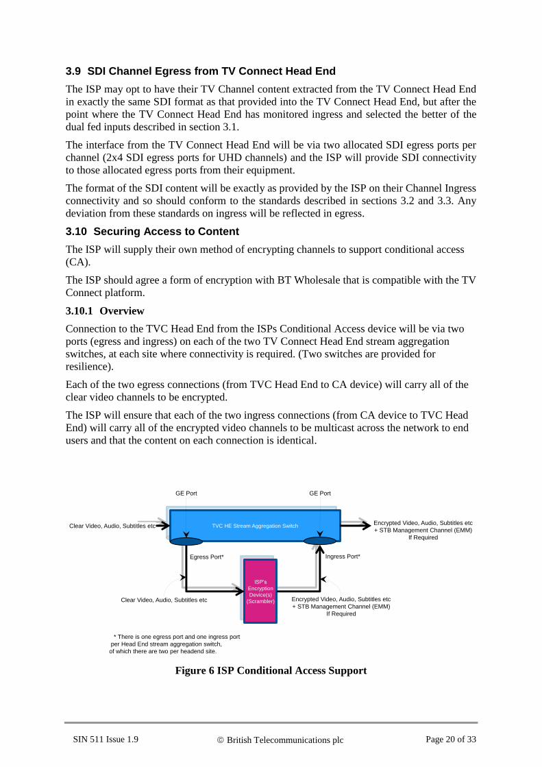
3.10.1 Overview
Connection to the TVC Head End from the ISPs Conditional Access device will be via two
ports (egress and ingress) on each of the two TV Connect Head End stream aggregation
switches, at each site where connectivity is required. (Two switches are provided for
resilience).
Each of the two egress connections (from TVC Head End to CA device) will carry all of the
clear video channels to be encrypted.
The ISP will ensure that each of the two ingress connections (from CA device to TVC Head
End) will carry all of the encrypted video channels to be multicast across the network to end
users and that the content on each connection is identical.
Figure 6 ISP Conditional Access Support
ISP’s
Encryption
Device(s)
(Scrambler)
TVC HE Stream Aggregation Switch
GE PortGE Port
ISP’s
Encryption
Device(s)
(Scrambler)
TVC HE Stream Aggregation SwitchEncrypted Video, Audio, Subtitles etc
+ STB Management Channel (EMM)
If Required
Clear Video, Audio, Subtitles etc
Clear Video, Audio, Subtitles etc Encrypted Video, Audio, Subtitles etc
+ STB Management Channel (EMM)
If Required
Ingress Port*Egress Port*
* There is one egress port and one ingress port
per Head End stream aggregation switch,
of which there are two per headend site.

SIN 511 Issue 1.9 British Telecommunications plc Page 21 of 33
3.10.2 Conditional Access
3.10.3 Interfaces between TVC Head End and ISP CA/Encryption device
The ISP may provide encryption devices (scramblers) for connection to the Head End. The
scrambler or scramblers can be located locally (within range of CAT5 cable, 100 metres
maximum) or remotely in a location to be agreed with the ISP. For scramblers that are remotely
located the ISP will be responsible for the provision of interconnecting access circuits and any
associated security arrangements.
Each pair of egress and ingress streams will be effectively inserted in the X and Y redundant
paths of the TV Connect Head End. Clear multicast programme streams are sent to the CA
System, with Encrypted Programme Streams being returned to the TV Connect Head End,
along with any supporting data streams (not supplied into the CA system from the TV Connect
Head end but inserted by the CA system) such as Entitlement Management Messages.
Two Gigabit Ethernet links (1000BASE-T) are presented to the ISP encryption device over cat
5/6 cables carrying clear channels [7].
Two Gigabit Ethernet ports (1000BASE-T) are available on the Head End to accept the
encrypted programme streams from the ISP [7].
All signals between the encryption system and the Head End will be carried over these physical
links.
It is assumed that the programme streams traversing these links will be properly conformed
MPEG2 Single Programme Transport Streams [2].
The ISP should provide a means of decryption (set top box or equivalent) for use by BT
Wholesale within the Head End to allow monitoring of TV channels post encryption.
3.10.4 Ports and Addressing
The multicast addresses and UDP port numbers for clear programme streams that ingress the
ISP encryption devices should be agreed with BT Wholesale.
The multicast addresses and UDP port number for encrypted programme streams that egress
the ISP encryption device should correspond to those agreed on the Customer Requirements
Form (CRF).
A default UDP port number of 5802 will be used on the CRF for the main programme stream
and a default UDP port number of 5804 will be used on the CRF for the FEC stream if it has
been selected by the ISP. Other UDP port numbers may be used by agreement via the CRF.
3.10.5 Entitlement Management Messages (EMM) Update/Announce
This section applies to any ISP that requires a management channel for EMM
Update/Announce. It is expected that this channel will be provided by the ISP as an additional
multicast MPEG2 transport stream [2] containing data only and that no FEC is required to be
applied to the channel. The data rate for the EMM Update/Announce channel is expected to be
of low rate in comparison to a Standard Definition channel, typically in the region of 100 kbit/s.
It is expected that this EMM Update/Announce channel will be transported over the same
links that carry the encrypted programme streams.

SIN 511 Issue 1.9 British Telecommunications plc Page 22 of 33
4. ISP Multicast Ingestion into TVC
4.1 Channel Ingress to TV Connect Head End.
Presentation of [ISP encoded and encrypted] programme sources from the ISP’s network to the
TVC Head End will be by Gigabit Ethernet links. The number of links provided will depend
on the resilience option selected by the ISP (see Section 2.1.4 above).
The ISP devices to be connected into the TVC Multicast Ingest Point (MIP) can be located
locally (within range of CAT5 cable, 100 metres maximum) or remotely in a location to be
agreed with the ISP. For devices that are remotely located the ISP will be responsible for the
provision of interconnecting access circuits and any associated security arrangements. BT
recommends the use of the Openreach Ethernet Access Direct (EAD) products.
At least two Gigabit Ethernet ports (1000BASE-T) are available on the TVC MIP to accept the
programme streams from the ISP [7], the location and number of ports is dependent on the ISP
option chosen as illustrated in Figure 2.
All signals between the ISP (encryption system) and the Head End will be carried over these
physical links.
It is assumed that the programme streams traversing these links will be properly conformed
MPEG2 Single Programme Transport Streams [2].
MIP will police ISP ingest bandwidth to ensure that:
The overall bandwidth offered by the ISP into TVC does not exceed the overall
bandwidth envelope agreed with BT Wholesale.
The individual channel bandwidth of each channel offered by the ISP into TVC does
not exceed the individual channel bandwidth agreed with BT Wholesale.
5. Summary of Potential Content Routeing and Processing Headend Options
This section gives an overview summary review of the Headend feature options an ISP may
take. The examples below are not exhaustive. There is potential for an ISP to use one or all of
these options contemporaneously and potentially different options at each of the Main and
Secondary Headend sites.
Figure 7 TVC HE Encoding
Figure 7 TVC HE Encoding shows the Headend architecture for the original TVC service.
TVC Headend
TVC Multicast
Distribution to ISPs
Consuming End UsersUncompressed
Content In from
ISP
Encoded
Content out to
ISP for
Encryption
Encoded
Encrypted
Content In from
ISP
ISP TV
End user

SIN 511 Issue 1.9 British Telecommunications plc Page 23 of 33
Figure 8 TVC SDI Egress
Figure 8 TVC SDI Egress shows the incremental option for an ISP to receive a copy of the
validated SDI feed that is being delivered to the TVC HE encoders.
Figure 9 TVC SDI Egress to ISP Encoding Platform
Figure 9 TVC SDI Egress to ISP Encoding Platform shows the option for an ISP to receive a
validated SDI feed to encode themselves and then return encoded encrypted content to the TVC
Headend for onward multicast distribution.
Figure 10 TVC Multicast Ingest Only
Figure 10 TVC Multicast Ingest Only shows the option for an ISP to deliver encoded encrypted
content to the TVC Headend for onward multicast distribution.
6. IP Multicast Streams
6.1 Maximum Bandwidth
The encoding options (whether encoded by the ISP or by TVC on behalf of the ISP) shall result
in SPTS Programme Channels having Multicast IP bandwidths in the Wholesale Network of
less than 30.00 Mbit/sec.
6.2 Channel Aggregation
The complete stream will be delivered as an IP Multicast for transport across the core of the
21C network.
TVC Headend
TVC Multicast
Distribution to ISPs
Consuming End UsersUncompressed
Content In from
ISP
Encoded
Content out to
ISP for
Encryption
Encoded
Encrypted
Content In from
ISP
ISP TV
End user
Uncompressed
Content Out to
ISP (SDI
Egress)
TVC Headend
TVC Multicast
Distribution to ISPs
Consuming End UsersUncompressed
Content In from
ISP
Encoded
Encrypted
Content In from
ISP
ISP TV
End user
Uncompressed
Content Out to
ISP (SDI
Egress)
TVC Headend
TVC Multicast
Distribution to ISPs
Consuming End Users
Encoded
Encrypted
Content In from
ISP
ISP TV
End user

SIN 511 Issue 1.9 British Telecommunications plc Page 24 of 33
6.3 Multicast Source and Group IP addresses
The ISP will be expected to complete a Customer Requirements Form (CRF) in conjunction
with BT Wholesale. Multicast group and source addresses, from a range of IP addresses owned
by BT Wholesale, will be allocated to individual TV Channels in agreement with the ISP.
The multicast group IP address is used to uniquely identify a particular TV channel.
The multicast source IP address is used to identify the network source equipment of the TV
channel within the TV Connect Head End and is required for multicast routing and geo-
resilient/TVC Protect failover.
6.4 Retransmission
In order to facilitate packet repair by retransmission by the ISP, a multiplex of all the channels
belonging to an ISP may be made available to the ISP at a small set of handover points, which
are to be agreed during contract negotiation.
Retransmission repair and control packets may be forwarded via the WBC data service. It is
recommended that an ISP make use of the priority best effort traffic marking for retransmission
repair and control traffic [10] in order to ensure a good experience for end users.
7. TV Connect Customer Premises Equipment (CPE) IGMP Requirements
7.1 Message Sequencing
It is expected that IGMPv3 will be used to signal access to TV Connect channels. An end user
will be joined to a selected channel via
Openreach GEA – fibre to the cabinet (FTTC) and fibre to the home (FTTP).
The IGMP messaging sequence is indicated below in Figure 11.

SIN 511 Issue 1.9 British Telecommunications plc Page 25 of 33
Figure 11 TV Connect IGMP flows
7.2 Set Top Box (STB) Functions
The set top box will generate IGMP join and leave messages in response to end user requests
(e.g. channel selection changes) and respond to IGMP query requests (from upstream network
equipment).
The set top box may use the WBC service to communicate with retransmission servers for
packet repair or access other ISP services.
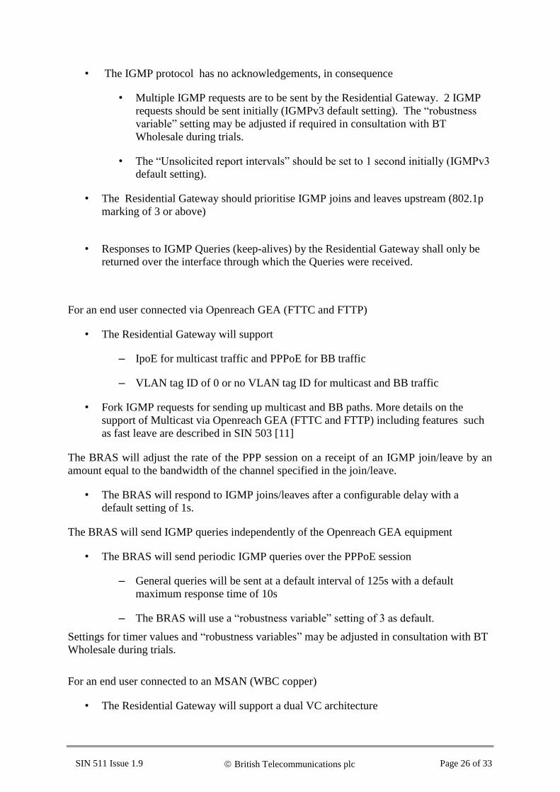
7.3 Residential Gateway (home router) Functions [5]
• The End user Residential Gateway (RG) acts as an IGMP proxy routing agent,
supports IGMP snooping and forks IGMP messages for sending up the TV Connect
and Broadband paths
• Support for IGMPv3 is required on the Residential Gateway
• The TV Connect product will only support IGMPv3 [1]
• The TV Connect product will support IGMPv3 Any Source Multicast (*,G).
• The TV Connect product will not support IGMPv3 Source Specific Multicast (S,G).
STB RG MSAN/OR GEA
DSLBRAS
Multicast Group to Bandwidth Table (maintained by OSS)
Unsolicited IGMP messages, and reports in response to queries
General & SpecificIGMP Queries
General & Specific IGMP Queries
Unsolicited IGMP messages
Multicast path
Broadband path
Key:
DownstreamBroadband Traffic
EU IGMP Domain
TV Connect Network IGMP sequence details
HierarchicalShaping
TV Connect Traffic
RG ForksIGMPmessages
12
2
34
7
56
SIN 511 Issue 1.9 British Telecommunications plc Page 26 of 33
• The IGMP protocol has no acknowledgements, in consequence
• Multiple IGMP requests are to be sent by the Residential Gateway. 2 IGMP
requests should be sent initially (IGMPv3 default setting). The “robustness
variable” setting may be adjusted if required in consultation with BT
Wholesale during trials.
• The “Unsolicited report intervals” should be set to 1 second initially (IGMPv3
default setting).
• The Residential Gateway should prioritise IGMP joins and leaves upstream (802.1p
marking of 3 or above)
• Responses to IGMP Queries (keep-alives) by the Residential Gateway shall only be
returned over the interface through which the Queries were received.
For an end user connected via Openreach GEA (FTTC and FTTP)
• The Residential Gateway will support
– IpoE for multicast traffic and PPPoE for BB traffic
– VLAN tag ID of 0 or no VLAN tag ID for multicast and BB traffic
• Fork IGMP requests for sending up multicast and BB paths. More details on the
support of Multicast via Openreach GEA (FTTC and FTTP) including features such
as fast leave are described in SIN 503 [11]
The BRAS will adjust the rate of the PPP session on a receipt of an IGMP join/leave by an
amount equal to the bandwidth of the channel specified in the join/leave.
• The BRAS will respond to IGMP joins/leaves after a configurable delay with a
default setting of 1s.
The BRAS will send IGMP queries independently of the Openreach GEA equipment
• The BRAS will send periodic IGMP queries over the PPPoE session
– General queries will be sent at a default interval of 125s with a default
maximum response time of 10s
– The BRAS will use a “robustness variable” setting of 3 as default.
Settings for timer values and “robustness variables” may be adjusted in consultation with BT
Wholesale during trials.
For an end user connected to an MSAN (WBC copper)
• The Residential Gateway will support a dual VC architecture

SIN 511 Issue 1.9 British Telecommunications plc Page 27 of 33
– Accept TV Connect multicast traffic on ATM VP/VC 0/35 with IpoE and
broadband traffic on ATM VP/VC 0/38 with PPPoE
– Fork IGMP requests for sending up multicast and broadband paths
• The MSAN will send periodic IGMP queries
– General queries will be sent at a default interval of 125s with a default
maximum response time of 100s.
– Specific queries will be sent at a default interval of 10s with a default
maximum response time of 8s.
The MSAN will use a “robustness variable” setting of 2 as default.
The MSAN will support the fast leave mode of IGMP.
For an ISP utilising the L2TP handover service option for WBC, the ISP will be expected to
provide similar IGMP aware line shaping functionality to that of the BT BRAS.
The ISP LNS will adjust the rate of the PPP session on a receipt of an IGMP join/leave by an
amount equal to the bandwidth of the channel specified in the join/leave.
• The ISP LNS will respond to IGMP joins/leaves after a configurable delay with a
default setting of 1s.
The ISP LNS will send IGMP queries independently of the Openreach GEA equipment
• The ISP LNS will send periodic IGMP queries over the PPPoE session
– General queries will be sent at a default interval of 125s with a default
maximum response time of 10s
– The LNS will use a “robustness variable” setting of 3 as default.
Settings for timer values and “robustness variables” may be adjusted in consultation with BT
Wholesale during trials.
8. Service Availability
Only a WBC customer (ISP) can take up the TV Connect service. The TV Connect service is
available to ISPs that take the WBC PTA (PPP termination and aggregation service) or L2TP
(Layer 2 tunnelling protocol) handover service.
An ISP can check the availability of Multicast at WBC exchanges by using the Broadband
Availability Checker available at http://www.btwholesale.com/ via the Routing and Planning
section under the Applications tab.
9. ISP Responsibilities
The ISP will be responsible for End User engagement, including client management (e.g. client
streaming, updates, and problem resolution)
SIN 511 Issue 1.9 British Telecommunications plc Page 28 of 33
The ISP specified Set Top Box will need to be capable of receiving TV Connect Streams,
decryption, and error recovery via retransmission and/or FEC [4].
The ISP will be responsible for connectivity to and live streaming content into the TVC Head
End and Conditional Access. TV channel content will be either:
• encoded in the TV Connect Head End, passed to the ISP for encryption then returned
to the Head End for onward multicast distribution over the network.
• Encoded in the ISP Head End delivered to the Head End for onward multicast
distribution over the network.
The ISP will be responsible for the Residential Gateway (home router) and set top box
functionality within the end user’s environment. The Residential Gateway (home router) will
proxy IGMP requests upstream onto the TV Connect path and into the Broadband PPP path
towards the BRAS.
The ISP will participate in collaborative testing to support BT Wholesale with provision and
repair of the TVC service.
The ISP will ensure that all technical details required to complete the CRF are provided.
The ISP will be responsible for packet repair via Retransmission.
For an ISP that takes the L2TP handover service the ISP will be responsible for IGMP aware
PPP session shaping functionality.

SIN 511 Issue 1.9 British Telecommunications plc Page 29 of 33
10. References
Protocol Standards:
[1] IGMPv3 IETF RFC 3376 Internet Group Management Protocol Version3
http://datatracker.ietf.org/doc/rfc3376/
[2] MPEG2 – TS ETSI TS 102 034 (V1.4.1): “Digital Video Broadcasting (DVB);
Transport of MPEG-2 TS Based DVB Services over IP Based
Networks”.
[3] SMPTE Society of Motion Picture and Television Engineers
https://beta.smpte.org/
[4] FEC SMPTE 2022-1-2007 Forward Error Correction for Real Time
Video/Audio Transport Over IP Networks
SMPTE 2022-2-2007 Unidirectional Transport of Constant Bit
Rate MPEG-2 Transport Streams on IP Networks
[5] TR101 Technical Report DSL Forum TR101 Migration to Ethernet based
DSL Aggregation April 2006– section 6 Multicast
[6] ITU ITU http://www.itu.int
BT.601 Studio encoding parameters of digital television for
standard 4:3 and wide screen 16:9 aspect ratios
BT.656 Interface for digital component video signals in 525-line
and 625-line television systems operating at the 4:2:2 level of
Recommendation ITU-R BT.601
[7] Gigabit Ethernet IEEE http://www.ieee802.org
IEEE 802.3ab – 1000BASE-T
[8] OP47 Free TV Australia Operational Practice OP- 47
Storage and distribution of teletext subtitles and
VBI data for high definition television
http://www.freetv.com.au/media/Engineering/OP_47_Issues_4_-
_Storage_and_Distribution_of_Teletext_Subtitle_and_VBI_Data
_for_High_Definition_Television_December_2008.pdf
[9] FacilityLine Plus Overview of FacilityLine Plus
https://www.btwholesale.com/pages/static/Products/Media_Broad
cast_and_Content/FacilityLine_Plus/index.htm
[10] SIN 472 BT Wholesale Broadband Connect (WBC) Products Service
Description
http://www.btplc.com/sinet/
[11] SIN 503 Generic Ethernet Access Service and Interface Description
http://www.btplc.com/sinet/
[12] Openreach
Broadcast
Access Products
https://www.openreach.co.uk/orpg/home/products/ethernetservice
s/broadcastaccess/broadcastaccess.do
For information on where to obtain these referenced documents, please see the document
sources list at http://www.btplc.com/sinet/

SIN 511 Issue 1.9 British Telecommunications plc Page 30 of 33
11. Abbreviations
21CN 21st Century Network
AC-3 Audio Coding 3 (Dolby Digital)
AD Audio Description
AD –BM Audio Description – Broadcaster Mix
AD-STBM Audio Description – Set Top Box Mix
AFD Active Format Description
ATM Asynchronous Transfer Mode
AVC Advanced Video Coding
BB Broadband
BEA Broadband Edge Aggregator
BM Broadcaster Mix
BRAS Broadband Remote Access Server
BT British Telecommunications plc
BTW BT Wholesale
CA Conditional Access
CAT5 Category 5 cable
CBR Constant Bit Rate
CPE Customer Premises Equipment
CRF Customer Requirements Form
DSL Digital Subscriber Line
DSLAM Digital Subscriber Line Access Multiplexer
DTT Digital Terrestrial TV
DVB Digital Video Broadcast
E-AC-3 Enhanced AC-3 (Dolby Digital Plus)
EAD Ethernet Access Direct [Openreach]
EEA Ethernet Edge Aggregator
EES Ethernet Edge Switch
EMM Entitlement Management Messages
EU End User
FEC Forward Error Correction
FTTC Fibre To The Cabinet
FTTH Fibre To The Home

SIN 511 Issue 1.9 British Telecommunications plc Page 31 of 33
GE Gigabit Ethernet
GEA Generic Ethernet Access (Openreach product)
HD High Definition
HE Head End
HE-AAC High Efficiency Advanced Audio Coding
IEA Infrastructure
IEEE Institute of Electronic and Electrical Engineers
IETF Internet Engineering Task Force
IGMP Internet Group Management Protocol
IP Internet Protocol
IpoE IP over Ethernet
ISP Internet Service Provider
ITU International Telecommunications Union
L2S Layer 2 switch
L2TP Layer 2 Tunnelling Protocol
LFE Low Frequency Effects (Channel used in surround sound)
LAC L2TP Access Concentrator
LNS Layer Two Network Server
MIP Multicast Ingest Point
MPEG2 Motion Picture Experts Group compression algorithm
MSAN Multi-Service Access Node
MSIL Multi-Service Interconnect Link
OSS Operational Support System
PON Passive Optical Network
PPP Point-to-Point Protocol
PPPoE Point-to-Point Protocol over Ethernet
PTA Point to Point Termination and Aggregation
RET Retransmission (packet repair)
RFC Request For Comment
RG Residential Gateway
s Seconds
SD Standard Definition
SDI Serial Digital Interface

SIN 511 Issue 1.9 British Telecommunications plc Page 32 of 33
SIN Supplier Information Note
SMPF Shared Metallic Path Facility
SMPTE Society of Motion Picture and Television Engineers
SPTS Single Programme Transport Stream
STB Set Top Box
STIN Supplier Trial Information Note
TV Television
TVC TV Connect
UDP User Datagram Protocol
UHD Ultra High Definition
VANC Vertical Ancillary data packet
VBI Vertical Blanking Interval
VC Virtual Circuit
VLAN Virtual Local Area Network
VP Virtual Path
WBC Wholesale Broadband Connect
WST World Standard Teletext
12. History
Issue Date Changes
STIN 1.0 13th January 2012 First Issue for Publication on http://www.sinet.bt.com
STIN 1.1 14th September 2012 STIN updated to reflect learning from Product Trials
SIN 1.0 18th December 2012 STIN raised to SIN
SIN 1.1 25th January 2013 SIN updated to clarify availability of TV Connect over WBC
Copper
SIN 1.2 26th March 2013 SIN updated to include L2TP handover option
SIN 1.3 25th July 2013 SIN updated to include alternative Head End trial and
clarification to audio description options
SIN 1.4 10th October 2013 SIN updated to include channel resilience via alternative
Head End as firm option
SIN 1.5 7th November 2013 SIN updated to include additional information on channel
capacity management and service availability
SIN 1.6 9th May 2014 SIN updated to include option for SDI egress connection
from Head End

SIN 511 Issue 1.9 British Telecommunications plc Page 33 of 33
Change of SINet site references from
http://www.sinet.bt.com to http://www.btplc.com/sinet/
SIN 1.7 23th July 2015 SIN updated to include UHD channel Specifications
SIN 1.8 SIN Updated to extend TVC offering to incorporate options
to ingest pre-encoded (ISP encoded) content. 16/10/2015.
Reviewed and updated 29/10/2015.
SIN 1.9 November 2016 SIN updated to extend TVC offering to support the ingest of
Audio Description Broadcaster Mix for encoding to delivery
an alternative Audio Description format to Receiver Mix.
Minor editorial updates for clarity on specification.
-END-