stepper motor basics - faulhaber.com · faulhaber application note 001 page 2 of 13 when using a...
TRANSCRIPT

APPLICATIONNOTE001
Page1 of 13
Stepper motor basics
What is a stepper motor?
A stepper motor is an electromechanical system which is transducing an electrical signal into a mechanical
one. It is designed to accomplish a discrete movement (notion of step) and reach a
precise position.
The movement is achieved through the use of a magnetic field provided by coils and
sensed by magnets. Indeed, when one of the coils is energized, a magnetic field is
created and, if the energy is supplied cyclically (by means of input pulses), then the
magnetic field will vary. When a magnet is placed in this varying magnetic field, it will
position itself in the lowest energy state (equilibrium), therefore providing motion.
This principle is used in the stepper motor, composed of a fixed part (the stator) made
of cyclically energized coils and a moving part (the rotor) made of ferromagnetic mate-
rial or magnets.
Why using a stepper motor?
Stepper motors do not operate as DC or brushless motors. They have no integrated electronics, no brushes
and can be controlled in open loop. To get a quick idea, stepper motors are very often considered as partic-
ular brushless motor that can be controlled without feedback in open loop. Thus, even though stepper motor
may look a bit more difficult to understand technically, they have the advantage of being very simple to con-
trol and need no encoder or special driver to monitor the position of the rotor.
Table 1 summarizes the differences between those 3 kinds of motor.
Step Motors DC Motors Brushless motors
Position with feedback Not really an option (cost) High resolution
depending on encoder
High resolution
depending on encoder
Positioning w/o
feedback
Good
24 steps/rev
High torque
none yes,
6 steps/rev
Moderate torque
Cost
(components)
Motor, 100 %¨
Encoder 40%
Driver chip, 5 %
Enc.Interface. 20 %
Controller 40 %
Total 145% (without encoder)
Total 205 % (with encoder)
Motor, 60 %
Encoder 40 %
Driver, 10 %
Enc.Interface. 20 %
Controller 40 %
Total 170 %
Motor, 150 %
Encoder 40 %
Driver, 20 %
Enc Interface 20 %
Control 60 %
Total 290 % (210% for BX4)
Acceleration Good
Limited to max. boost running toque
Very High
Boost operation reduces brush life
Very High
Top Speed <15‘000rpm <15‘000 rpm > 15‘000 rpm
Life Time Very good Limited by wear oft he brushes Very good
Stability Very high, inherent ƒ(Enc.res; controller) ƒ(Enc.res; controller)
Reliability High (no brushes / no Hall sensors) Low (brushes) High (no brushes)
Table 1 : Comparison between different motor technologies. This is an estimation and can be discussed from case to case.
Figure 1: PRECIstep®.
stepper motor.

Faulhaber Application Note 001 Page 2 of 13
When using a stepper motor?
Stepper motors are suitable for applications where compact and robust solutions are required. They develop
their maximum torque at stand-still which makes them naturally suitable to hold a position. The external
commutation ensures that the speed is perfectly constant even if the load varies. Thanks to the absence of
any electronic component, stepper motors run where the hall sensors or encoders of other type of motor
find their limit: high/low temperatures, external noise disturbances, etc.
Compared to a DC motor, a stepper motor is also much easier to use for positioning application as the no-
tion of step enables the user to know the precise position or displacement of the rotor without feeback: it
runs in open loop.
Stepper motors are as a matter of fact frequently used when the following application requirements are
specified:
- Repetitive positioning tasks with high accelerations (i.e. XYZ of machine tools) - Whenever the settling time must be short and with repeatable discrete positions. - Whenever open loop (absence of electronics) makes sense (e.g. for noise immunity). - For back and forth motions. - Frequent “start/stop” operation. - Whenever the duty cycle is relatively small. (Time ON << Time OFF) - Whenever the actual position must be held with high torque. - Whenever the actual position must be held when no current is applied (thanks to the residual
torque). - Whenever long life times is required (i.e. using the brushless design). - Whenever minor speed variation under load are not allowed (peristaltic pumps, XYZ of machine
tools) - For most small consumer electronic devices, such as hard disc drives, ink jet printers, cameras.
By contrast FAULHABER PRECISTEP focuses on the following market segments:
- Optical systems (e.g. zoom, focus, pan/tilt, and filter positioning, microscope stages)
- Photonics (e.g. laser tuning, laser scanner)
- Telecommunications (e.g. variable optical amplifiers (VOA))
- Medical (e.g. pumps, DNA analyzers)
- Instrumentation (e.g. gas analyzer)
- Aerospace & Defense (e.g. UAVs)
Stepper motors categories and operation
There are basically three different stepper motor design types on the market:
- The permanent magnet (PM) design
- The variable reluctance design
- The hybrid design

Faulhaber Application Note 001 Page 3 of 13
The permanent magnet (PM) design (Figure 2a)
The rotor includes permanent magnets positioned in order to alternatively obtain South and North poles,
which can interact with the varying magnetic field of the stator.
Rotation is achieved by alternatively energizing the stator coils A-B-C-D and attracting the North (or South)
pole of the rotor to the magnetized stator pole. When no current is applied, a small torque is required to
move the rotor from its equilibrium position due to the interaction between the permanent magnets and the
stator. This is indifferently referred to as residual, detent or cogging torque in the technical literature or in
manufacturers’ brochures.
This design is the most popular for small stepper motors, especially below ø20mm, and provides high
torque. The resolution is usually limited to 20 or 24 steps per revolution. PRECIstep® stepper motor tech-
nology falls exclusively into this category.
The variable reluctance design (Figure 2b)
Variable reluctance stepper motors consist of a more complicated design and require an accurate manufac-
turing of both the stator and the rotor. The rotor, made of a ferromagnetic material (e.g. iron) has several
teeth, which can be attracted to the stator poles. Once the stator coils are cyclically energized, the teeth of
the rotor will be attracted and will tend to align themselves with the magnetized stator poles, thus resulting in
a rotational movement. Despite the fact that higher resolutions are achieved (due to the higher number of
steps per revolution), variable reluctance stepper motors provide a rather small dynamic torque. Hence, this
design is not used for the smallest motors. As the rotor does not include permanent magnets, there is no
risk when using this type of stepper motor in a strong external magnetic field (e.g. in MRI devices). One of
the main drawback of this design apart from the low torque is that it does not hold its position when no cur-
rent is applied (i.e. there is no residual torque).
The hybrid design (Figure 2c)
The concept is to have a permanently magnetized rotor with multiple teeth and a stator with multi-toothed
poles, in order to combine a rotational movement by stator poles alignment and stator teeth attraction.
The hybrid design therefore combines the high torque of PM stepper motors with the higher resolution of the
variable reluctance design. A very common resolution of hybrid stepper motors is 200 steps per revolution.
The manufacturing of hybrid stepper motors is technically limited to a minimum size of ø19mm
(a) (b) (c)
Figure 2 : (a) Permanent magnet, (b) variable reluctance and (c) hybrid stepper motors. [5]

Faulhaber Application Note 001 Page 4 of 13
Physics basics
To understand the main parameters that influence the performances of the motor, it is important to have an
overview of the physics behind it.
Figure 3 presents the schematic of a stepper motor represented by a torque-speed factor (kTω), an electri-
cal resistance (R, windings) and an inductance (L, windings). U is the applied voltage and I the current in
the windings.
The main formula expressing the behavior of the motor is given by equation 1.
dt
dILtkRIU T (1)
Where
• RI = Voltage to drive current (resistance times current)
• kT ω(t) = Voltage to compensate the back-EMF1 (kT is the torque constant and ω the speed)
• LdI/dt = Voltage to establish/modify current level
The torque is directly proportional to the current and can be expressed by equation 2.
IkM T (2)
As a consequence, the current can be deducted from the previous formula as shown in equation 3.
R
tke
R
UI
R
dt
dILtkU
I Tt
L
RT
1 (3)
Figure 4 shows the current in the windings in function of time (ideal case where back EMF is null). Due to
the inductance of the motor, it takes some time for the current to reach its maximum value.
1 The back EMF is the abbreviation of back Electromotive Force. It corresponds to the voltage sensed when the rotor is
moving in a changing magnetic field.
Figure 3 : Schematic of a stepper motor
Tk

Faulhaber Application Note 001 Page 5 of 13
From this we can immediately conclude that the factors which influence the current, thus the torque, are:
• Inductance (LdI/dt, L = winding inductance) The inductance prevents the current to establish rapidly in the phases.
• Resistance (R = winding resistance) The resistance influences the maximal current set in the phase.
• The back EMF When the speed ω increases, the back-EMF proportional to kTω increases and the current decreases, hence the torque decreases. This explains why we observe on the torque/speed curves of the data sheet that the torque declines when speed increases whatever the operation mode of the motor.
How does a stepper motor rotate?
From now on, we will concentrate on permanent magnet stepper motors, which are the ones designed and
manufactured by PRECIstep®.
Figure 5 shows a simplified schematic of the operation for a two-phase permanent magnet stepper motor
and Figure 6 the corresponding energizing sequence of the coils (clockwise rotation). For a counter-
clockwise rotation, the sequence must be reversed.
Figure 4 : Current in function of time. Current switched ON at t=0 and switched OFF at t=t1. Note that in this case the back EMF is set
to 0. At high rotational speed, the back EMF may significantly modify this behavior.

Faulhaber Application Note 001 Page 6 of 13
Step Phase A Phase B
Pin 1 Pin 2 Pin 3 Pin 4
1 + -
2 + -
3 - +
4 - +
As one coil is energized, a magnetic field is created and attracts the North or South pole of the magnet,
depending on the polarity of the energized coil. By alternatively energizing the different coils (giving birth to
a sequence), it is then possible to rotate the magnet
Figure 5 : Operation of a permanent magnet stepper motor (“one phase-on” configuration).
Figure 6 : Energizing sequence of permanent magnet stepper motor (“one phase-on” configuration).

Faulhaber Application Note 001 Page 7 of 13
Phase, poles and step angle
Usually, stepper motors have 2 phases, but some of them may also have 3 or 5 phases.
Bipolar stepper motors usually use one winding per phase because the current in the winding can be made
to circulate in both directions. Unipolar stepper motors use one winding per phase with a tap in the middle;
hence, half of the winding is used for positive current flow and half for negative current flow (corresponding
to two separate coils). FAULHABER PRECISTEP designs and manufactures only bipolar stepper motors.
A pole is defined as a region where the magnetic flux density is concentrated. It corresponds to the North or
the South “pole” of a magnet. PRECIstep® stepper motors feature either 10 or 12 poles (corresponding to 5
or 6 pole pairs) in combination with 2 phases, which leads to 20 or 24 steps per revolution.
The step angle is determined by the number of steps, for instance a stepper motor with 20 steps will define
a step angle of 18°(=360°/20)
NPhN
angleStepPh
360360
(4)
Where
• NPh = number of equivalent poles per phase = number of rotor poles
• Ph = number of phases
• N = total number of poles for all phases together
One phase-on and Two phase-on
There are two main ways to energize a stepper motor (when operating in full steps). Either 1 phase is ener-
gized at a time (“1 phase-ON” configuration) or 2 phases are energized at the same time (“2 phase-ON”
configuration). For the “1 phase-ON” configuration, the commutation sequence is A+=> B+=> A-=> B- for a
direction and A+=> B-=> A-=> B+ for the opposite rotation direction. For the “2 phase-ON” configuration,
the sequence is A+B+=> A-B+=> A-B-=> A+B- for one direction of rotation and A+B+=> A+B-=> A-B-=> A-
B+ for the other direction.
The evolution across time of both phase current signals for each type of configuration is different, as illus-
trated in Figure 8. The clock pulse signal (green), corresponding to the commutation speed, determines the
rotation speed of the rotor. If the same torque of both “1 phase-ON” and “2 phase-ON” configurations is
required, then the current applied in the “1 phase-ON” configuration must be √2 times higher than the cur-
rent applied in the “2 phase-ON” configuration (same power consumption).
Figure 7 : Position of the rotor during (left) “1 phase-ON” and (right) “2 phase-ON” operation.

Faulhaber Application Note 001 Page 8 of 13
To understand why the current must be √2 times higher in 1 phase-ON operation to obtain the same torque than in 2 phase-ON operation, Figure 9 below can help :
When 2 phases are energized at a time, the sum of the vector equals √2 times the separate value of one phase, which explains why the current in 1 phase-ON must be higher to obtain the same torque at the out-put.
Full-stepping and half-stepping
When alternating both “1 phase-ON” and “2 phase-ON” operations, the rotor can achieve half-steps. The
commutation sequence is thus given by A+=>A+B+=>B+=>B+A-=>A-=>A-B-=>B-=>B-A+, which is twice the
number of steps obtained with full-step operation, the step angle also being halved. For counter-clockwise
rotation, the sequence is just reversed. If the same torque between each half step is required, then the
current applied in the “1 phase-ON” configuration must be √2 times higher than the current applied in the “2
phase-ON” configuration (see paragraph 1.8).
Figure 8 : Evolution of phase current signals (lilas for phase A; light blue for phase B) for (left) “1 phase ON” configuration and (right)
“2 phase-ON” configuration operation. The clock pulse (green signal) determines the rotation speed.
Figure 9 : (left) 1 phase-ON vectorial representation and (right) 2 phase-ON vectorial representation.
Current must be √2 x higher than in 2 phases ON

Faulhaber Application Note 001 Page 9 of 13
Micro stepping
For operation at low speed (typically below 600 rpm) or if a resolution of less than a half-step is required,
micro stepping is the ultimate solution. By properly energizing the windings, it is possible to move the rotor
less than a degree. Most drivers can support such an operating mode .The idea is to energize two coils in
such a way, that the rotor will position itself according to a smaller step angle. By extension, supplying each
phase current in form of a sine wave allows the stepper motor to achieve a very high degree of resolution.
Such an operating mode is explained in more detail in the separate micro stepping application note.
(a) (b)
Figure 10 : Evolution of phase current signals (lilas for phase A; light blue for phase B) for half-stepping operation, with phase current
compensation.
Figure 11 : (left) Phases current for micro stepping operation (8 microteps/step in this case). (right) Shape of the signal
for one phase at different micro stepping modes. The current signal tends to be sinusoidal. [6]
Faulhaber Application Note 001 Page 10 of 13
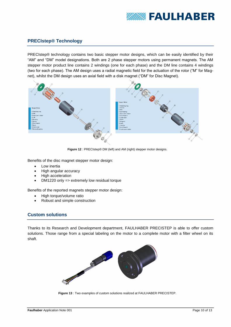
PRECIstep® Technology
PRECIstep® technology contains two basic stepper motor designs, which can be easily identified by their
“AM” and “DM” model designations. Both are 2 phase stepper motors using permanent magnets. The AM
stepper motor product line contains 2 windings (one for each phase) and the DM line contains 4 windings
(two for each phase). The AM design uses a radial magnetic field for the actuation of the rotor (“M” for Mag-
net), whilst the DM design uses an axial field with a disk magnet (“DM” for Disc Magnet).
Benefits of the disc magnet stepper motor design:
• Low inertia
• High angular accuracy
• High acceleration
• DM1220 only => extremely low residual torque
Benefits of the reported magnets stepper motor design:
• High torque/volume ratio
• Robust and simple construction
Custom solutions
Thanks to its Research and Development department, FAULHABER PRECISTEP is able to offer custom
solutions. Those range from a special labeling on the motor to a complete motor with a filter wheel on its
shaft.
Figure 13 : Two examples of custom solutions realized at FAULHABER PRECISTEP.
Figure 12 : PRECIstep® DM (left) and AM (right) stepper motor designs.

Faulhaber Application Note 001 Page 11 of 13
Successful PRECIstep® stepper motor applications
PRECIstep® stepper motors are predominantly sold for medical and optical applications, but it is truly not
confined to those two market segments. The idea of this section is to present some successful applications
realized with PRECIstep® stepper motors.
Drug delivery pump (medical application)
The battery powered drug delivery pump (e. g. insulin pumps used against diabetes or pain treatment
pumps) application field is growing of interest. Therefore, many medical manufacturers try to design and
develop their own pump. In such devices, a motor is usually used to rotate or position a piston that controls
the injection of the drug. The motor operates infrequently (time ON<< time OFF), must hold the position
without current and move the piston at a very steady speed. Together with the requirement for a simple and
compact electronic, the stepper motor truly makes sense.
Hand-held X-ray analyzer (instrumentation application)
The hand-held X-ray analyzer enables to scan a metal object and characterize its composition. The role of
the stepper motor is to position a metal filter wheel in order to calibrate the device. The very short length of
the stepper motor and its easy to integrate control electronic are appreciated by the manufacturers of such
equipment.
Figure 14 : Insulin pump with a schematic representation of the internal design using the stepper motor.
Figure 15 : Hand-held X-ray analyzer (left) and an example of filter wheel integrating a stepper motor (right).

Faulhaber Application Note 001 Page 12 of 13
X-Y microscope stage (optical application)
Stepper motors are also widely used in optical elements, which are often integrated in other applications
(medical, instrumentation, defense, etc.). In this example, the stepper motor is used to move a microscope
stage. Again, the stepper motor naturally makes sense since it’s a compact drive and the open loop control
cannot be faulted since the operator of the microscope visually actually control the position.
Gyroscopic camera (defense application)
Unmanned planes, also known as drones, need cameras with high stability and image precision. Hence, the
integration of stepper motors in such systems to control either the zoom /focus of the image or the pan/tilt of
the camera.
Product codification
The correct code for ordering a PRECIstep® stepper motor is illustrated below for an AM1524 motor:
AM15242R025007 Complete motor designation
AM15242R025007 Design type
AM15242R025007 Diameter in mm
AM15242R025007 Number of steps per revolution
AM15242R025007 Bearing/lubricant type
AM15242R025007 Winding type
AM15242R025007 Execution (shaft, pinion, PCB, etc.)
FAULHABER PRECISTEP also offers drivers, lead screws with nut and bearing, special lubricants, gear-
head solutions and cables.
Figure 16 : Picture of microscope stage
Figure 17 : Unmanned observation plane (left), with a closer view of the camera system (right).

Faulhaber Application Note 001 Page 13 of 13
References
[1] S. Motor, D. Considerations, and C. Problems, “APPLICATION NOTE STEPPER MOTOR DRIVER CONSIDERATIONS,” no.
December 2003, pp. 1–11.
[2] “Lead Screw Efficiency.” [Online]. Available: http://www.askltd.co.jp/eng/technical_info/feed_screw. [Accessed: 19-Jun-2013].
[3] “Better Soldering.” [Online]. Available: http://www.elexp.com/t_solder.htm. [Accessed: 20-Jun-2013].
[4] “Eddy Currents.” [Online]. Available: http://en.wikipedia.org/wiki/Eddy_current. [Accessed: 20-Jun-2013].
[5] “Stepper motor types.” [Online]. Available: www.anaheimautomation.com. [Accessed: 18-Jun-2013].
[6] Trinamic, “TMC223 Datasheet.” [Online]. Available:
http://www.trinamic.com/tmctechlibcd/integrated_circuits/TMC223/TMC223_datasheet.pdf. [Accessed: 18-Jun-2013].
[7] “The right and wrong of soldering.” [Online]. Available: http://karma-laboratory.com/petridish/2005/01/the_right_and_w.html.
[Accessed: 20-Jun-2013].
Legal notices
Copyrights. All rights reserved. No part of this Application Note may be copied, reproduced, saved in an information
system, altered or processed in any way without the express prior written consent of Dr. Fritz Faulhaber & Co. KG.
Industrial property rights. In publishing the Application Note Dr. Fritz Faulhaber & Co. KG does not expressly or im-
plicitly grant any rights in industrial property rights on which the applications and functions of the Application Note de-
scribed are directly or indirectly based nor does it transfer rights of use in such industrial property rights.
No part of contract; non-binding character of the Application Note. Unless otherwise stated the Application Note is
not a constituent part of contracts concluded by Dr. Fritz Faulhaber & Co. KG. The Application Note is a non-binding
description of a possible application. In particular Dr. Fritz Faulhaber & Co. KG does not guarantee and makes no rep-
resentation that the processes and functions illustrated in the Application Note can always be executed and implement-
ed as described and that they can be used in other contexts and environments with the same result without additional
tests or modifications.
No liability. Owing to the non-binding character of the Application Note Dr. Fritz Faulhaber & Co. KG will not accept any
liability for losses arising in connection with it.
Amendments to the Application Note. Dr. Fritz Faulhaber & Co. KG reserves the right to amend Application Notes.
The current version of this Application Note may be obtained from Dr. Fritz Faulhaber & Co. KG by calling +49 7031 638
385 or sending an e-mail to [email protected].