stepped overtopping protection for dams...stepped overtopping protection for dams by kathleen h....
TRANSCRIPT

PAP-612 HYDRAULICS BRANCH OFFICIAL FILE COPY
""'" nvru-'uWElJ RETURN PROMPTL'
STEPPED OVERTOPPING PROTECTION FOR DAMS
z
K. H. FRIZELL AND B. W. MEFFORD
PAP

STEPPED OVERTOPPING PROTECTION FOR DAMS
By Kathleen H. Frizelll and Brent W. Meffor&
ABSTRACT: Passing flows over the top of a dam has recently become a more acceptable alternative to expensive service or emergency spillways. Use of (RCC) roller-compacted concrete in dam construction provides the opportunity to build a stepped spillway right into the dam. We will present background and available hydraulic design information on stepped spillways for RCC dams with plans for Reclamation's future work.
In this area, Reclamation's most current research has emphasized the use of concrete steps to protect an embankment dam during overtopping. Laboratory testing of step geometries shows great promise for producing a stable protective overlay that will also dissipate now energy. Reclamation's new large-scale flume testing facility will be used to confirm laboratory results and extend the use of stepped protection for embankment dams. A video tape of this 50-ft-high (15.2-m-high) facility with individual step-shaped blocks will accompany this paper.
INTRODUCTION
Roller compacted concrete (RCC) has easily become the most popular method for building new concrete dams and/or rehabilitating many types of existing dams in the U.S. Reemergence of stepped spillways is attributed to the RCC horizontal lift placement techniques of which a stepped surface is a natural outcome. Usually the secondary reason is the potential for dissipation of the flow energy as it travels down the steps to the toe of the dam. Energy dissipation also provides a cost benefit due to the reduced stilling basin length or entire elimination of the required basin. The step shape has been obtained in many ways. Steps have been shaped from unformed or formed RCC, and standard formed or slip-formed conventional concrete with or without reinforcement.
Reclamation's (USBR) first RCC experience was the construction of Upper Stillwater Dam about 80 miles (128.7 km) east of Salt Lake City, Utah. A stepped spillway covering a portion of the downstream dam face is capable of passing the Probable Maximum Flood (PMF).
1 Hydraulic Engineer, Research and Laboratory Services Division, Hydraulics Branch, Bureau of Reclamation, PO Box 25007, Denver CO 80225
2 Head, Hydraulic Structures Section, Research and Laboratory Services Division, Bureau of Reclamation, PO Box 25007, Denver CO 80225
1
Successes with RCC placement, producing quick results and low cost, have made RCC extremely popular in the dam building industry. Application has now extended from new dam construction to dam rehabilitations, including existing concrete, crib, embankment, and rockfill dams. Reclamation now has increased interest in applying concrete stepped overlays to protect high embankment or rockfill dams during overtopping events. This interest is a direct result of increased PMF requirements producing deficiencies in present dams and the high costs of traditional Dam Safety remedies. A cooperative research program funded by Reclamation's Dam Safety (SOD) and Water Technology and Environmental Research (WATER) programs, and the Electric Power Research Institute (EPRI) is now being conducted to determine the hydraulic properties of stepped spillway applications.
The problem with using stepped spillways has been, and continues to be, the lack of general design criteria that quantifies the energy dissipation characteristics of the steps for a given unit discharge, flow depth, and hydraulic dam height. Steps have proven effective for small unit discharges, where the step height clearly influences the flow. The need to pass larger flows has pushed designs beyond the limitations of the present data base.
The main objective of Reclamation's stepped spillway research program is to define energy dissipation properties of steps for concrete and embankment dams while producing a stable, protective, stepped overlay for an embankment.
STEPPED SPILLWAY FOR RCC DAMS
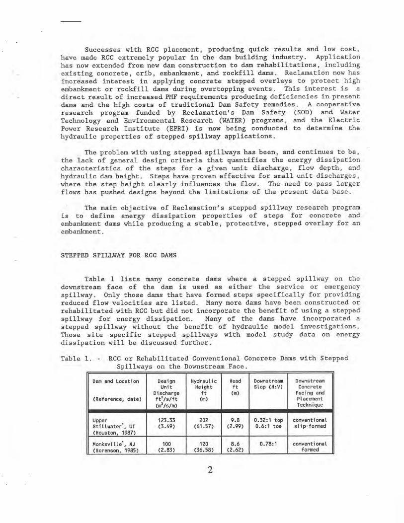
Table 1 lists many concrete dams where a stepped spillway on the downstream face of the dam is used as either the service or emergency spillway. Only those dams that have formed steps specifically for providing reduced flow velocities are listed. Many more dams have been constructed or rehabilitated with RCC but did not incorporate the benefit of using a stepped spillway for energy dissipation. Many of the dams have incorporated a stepped spillway without the benefit of hydraulic model investigations. Those site specific stepped spillways with model study data on energy dissipation will be discussed further.
Table 1. - RCC or Rehabilitated Conventional Concrete Dams with Stepped Spillways on the Downstream Face.
Dam and Location Design Hydraulic Head Downstream Downstream Unit Height ft Slop (H:V) Concrete
Discharge ft (m) Facing and (Reference, date) ft3/s/ft (m) Placement
(m3/s/m) Technique
Upper 123.33 202 9.8 0.32:1 top conventional Stillwater`, UT (3.49) (61.57) (2.99) 0.6:1 toe slip-formed
(Houston, 1987)
Monksville*, NJ 100 120 8.6 0.78:1 conventional
(Sorenson, 1985) (2.83) (36.58) (2.62) formed
2

Dam and Location Design Hydraulic Head Downstream Downstream Unit Height ft Slop (H:V) Concrete
Discharge ft (m) Facing and (Reference, date) ft3/s/ft (m) Placement
(m3/s/m) Technique
Stagecoach% CO 39 140 4.72 0.8:1 conventional
(Stevens) (1.10) (42.67) (1.44) formed
De Mist KraaL', 110 59 9.8 0.6:1 conventional
South Africa (3.11) (17.92) (2.99) formed
(Jordaan, 1986)
Zaaihoek, South 55 120 6.2 0.62:1 conventional Africa (1.56) (36.58) (1.89) slip-formed
Lower Chase 35.95 59 4.50 0.70:1 conventional Creek, AZ (1.02) (17.98) (1.37) formed
Milltown Hill', 154.2 180 11.24 0.75:1 conventional
OR (Frizell, (4.36) (54.86) (3.43) sLip-formed
1990)
Middle Fork, Co Overtops 124 ? 0.8:1 conventional for Events (37.80) formed > 500 yrs.
Knellpoort, South 90 141.4 7.8 0.60:1 conventional Africa (2.55) (43.10) (2.38) formed
Santa Cruz, NM 43 120 5.5 0.65:1 conventional (1.22) (36.58) (1.68) formed
Bucca Weir', 98 39 121.4 0.5:1 conventional
Australia (2.77) (11.29) (37.0) formed
Jequitai% Brazil 98.9 118.8 6.87 0.80:1 proposed
(Frizell, 1992) (2.80) (36.21) (2.09) formed RCC
Junction Falls 123 29.5 7.5 0.875:1 conventional Dam, WI (3.48) (8.99) (2.29) formed
Les Olivettes, 78 103.35 9.84 0.75:1 conventional France (2.21) (31.50) (3.00) formed
Cedar Falls, WA 30 25 4.68 0.80:1 conventional (0.85) (2.62) (1.43) formed
New Victoria, 115 0.325:1 conventional Australia (35.05) top slip-formed
0.80:1 toe
Riou, France 67.6 0.6:1 conventional (20.60 slip-formed
Sheep Creek 115 325 10 0.7:1 conventional Tailings (3.25) (99.06) (3.05) formed Retention Dam, Alaska
Wotwedans, South 275 0.5:1 conventional Africa (83.82) formed
*Stepped spillway designs were determined by hydraulic model studies.
Previous Hydraulic Model Studies of Stepped Spillways for Concrete Dams
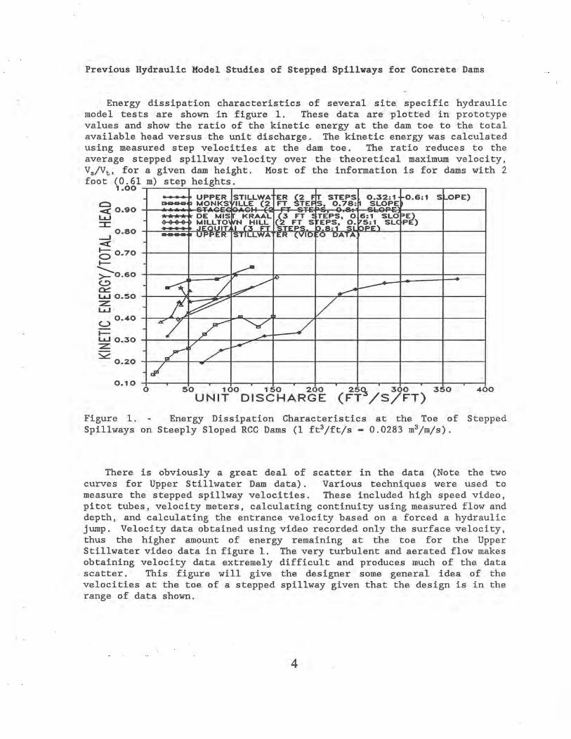
Energy dissipation characteristics of several site specific hydraulic model tests are shown in figure 1. These data are plotted in prototype values and show the ratio of the kinetic energy at the dam toe to the total available head versus the unit discharge. The kinetic energy was calculated using measured step velocities at the dam toe. The ratio reduces to the average stepped spillway velocity over the theoretical maximum velocity, VS/Vt, for a given dam height. Most of the information is for dams with 2 foot (0.61 m) step heights.
1.00
Q 0.90 W
0.80 J Q
0.70
0.60
W 0.50 Z W
0.40 U
W 0.30 Z
Y 0.20 -
0.10 -r O
I I==
- WM4 I W-.
are 50 160 150 200 2505 300 350 460
UNIT DISCHARGE (FT /S/FT)
Figure 1. - Energy Dissipation Characteristics at the Toe of Stepped Spillways on Steeply Sloped RCC Dams (1 ft3/ft/s — 0.0283 m3/m/s).
There is obviously a great deal of scatter in the data (Note the two curves for Upper Stillwater Dam data). Various techniques were used to measure the stepped spillway velocities. These included high speed video, pitot tubes, velocity meters, calculating continuity using measured flow and depth, and calculating the entrance velocity based on a forced a hydraulic jump. Velocity data obtained using video recorded only the surface velocity, thus the higher amount of energy remaining at the toe for the Upper Stillwater video data in figure 1. The very turbulent and aerated flow makes obtaining velocity data extremely difficult and produces much of the data scatter. This figure will give the designer some general idea of the velocities at the toe of a stepped spillway given that the design is in the range of data shown.
0

Research on Stepped Spillways for Concrete Dams
One objective of Reclamation's research program is to better quantify the velocity or energy remaining in the flow at the toe of a steeply sloped concrete dam with a stepped spillway. Low construction costs and energy dissipation are the primary reasons for using stepped spillways with new or rehabilitated concrete dams. This will improve safe designs of these spillways with appropriate and cost effective stilling basin lengths.
To accomplish this end, Reclamation is currently constructing a 1.5-ft-wide (0.46 m) Plexiglas-walled flume facility for studying steep (0.5:1 to 0.8:1) sloped stepped spillways typical of RCC dams. This facility will have a free overfall ogee crest shape that allows the flow to cling to the face of the spillway until meeting the constantly sloping portion of the spillway. The ogee shape is designed with steps that transition in size until the full step height is reached at the point of tangency with the spillway slope. The sloping flume flows into a 30-ft-long (9.14 m) tailbox to study the formation of the hydraulic jump. It is hoped that this facility will allow the limits of the capability of stepped spillways to dissipate energy to be determined.
STEPPED SPILLWAYS FOR EMBANKMENT DAMS
Dam Safety inspections have concluded that a large number of both small and large embankment dams are unsafe due to predicted overtopping during extreme flood events. Construction of RCC protection for overtopping flow on existing or new embankment or rockfill dams has proven to be very cost effective. The present emphasis of the research program on stepped spillways is on the hydraulic properties produced by the steps on flatter slopes more common to embankment dams. This also has led to determining the step geometry that provides the most stable overlay with energy dissipation characteristics of secondary importance. Embankment dams which have been protected with RCC or are planned for rehabilitation range in height from about 20 ft (6.1 m) to as much as 119 ft (36.3 m).
Increased PMF forecasts have produced numerous low and high dams with inadequate spillway capacity in all business sectors. As a result, Reclamation's Dam Safety and Research Programs have taken the lead in providing funding for investigation of stepped spillway dam overtopping protection.
Stepped Spillway Protection on a 2:1 Slope
Emphasis is currently focused on providing stepped protection for embankment dams ranging in downstream embankment slope from 2:1 to 4:1. Reclamation's flume facility for embankment dam slope investigations has been in operation since January of 1990, figure 2. The facility allows
5

I
i I _
Figure 2. - Overall View of Sloping Flume Facility.
investigation of model unit discharges up to 14 ft3/s/ft (0.40 m3/s/m) under reservoir heads up to 2.8 ft (0.85 m). The total drop from the reservoir to the controlled tailwater is 15.5 ft (4.7 m).
Primary importance for embankment dam overtopping protection is placed upon the stability of the stepped concrete overlay. Research is focused on enhancing stability by providing continuous aspiration of subgrade seepage by virtue of the flow characteristics over the stepped surface. Aspiration is suction of the fluid from underneath the overlay produced by the pressure differential created by the high velocity flow over the step offset area. For embankment dam protection, the benefit of energy dissipation and reduced velocities at the dam toe are of secondary consideration. A series of three step geometries were investigated. For each geometry, the flow depth, pressure profiles on the steps at chosen locations, and velocity profiles (every ten steps beginning at the third step downstream from the crest), were recorded. The step geometry has been optimized to produce a zone of subatmospheric pressure to relieve buildup of seepage pressure under the overlay.
Results of 2:1 Sloping Embankment Tests
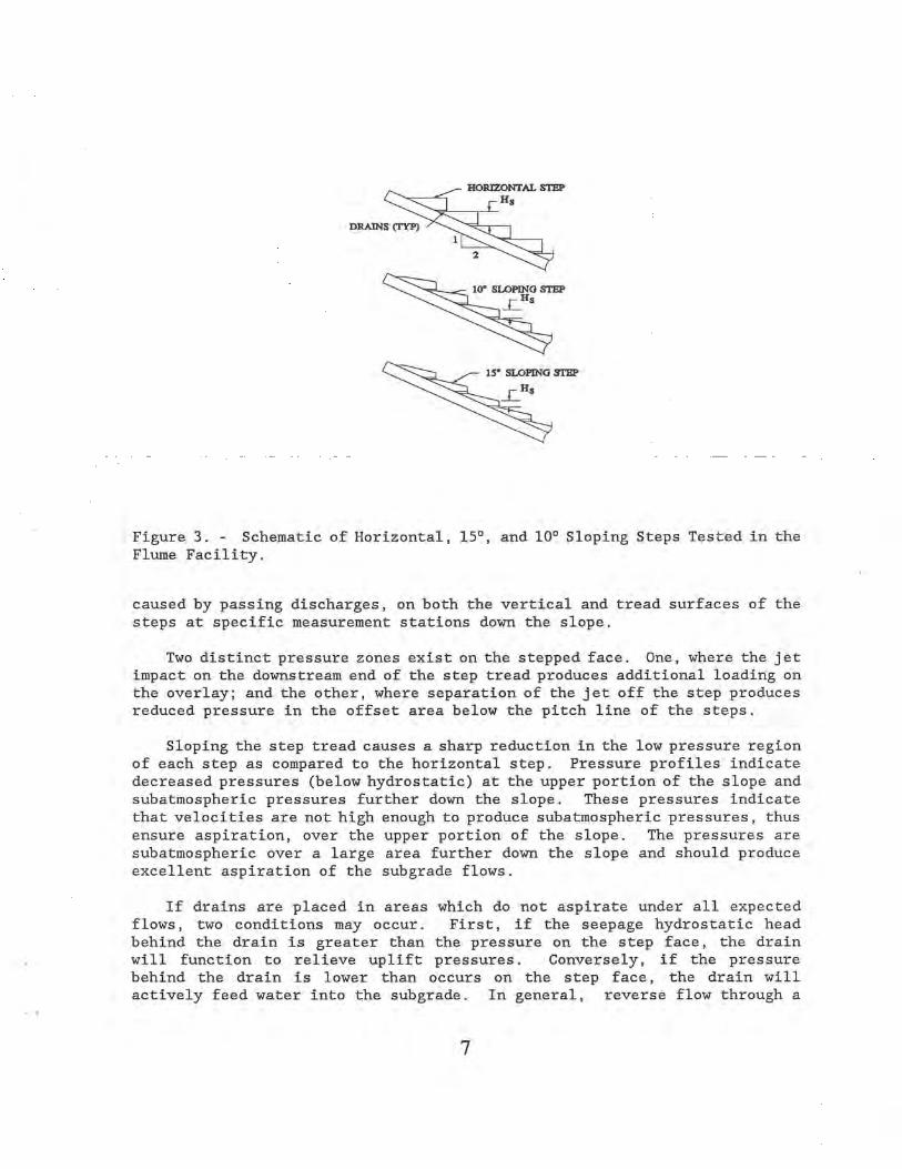
The three step shapes investigated had horizontal tread and tread sloped downward at 15° and 10°, as shown on figure 3. Model steps were continuous in width and had a 4 inch (0.1 m) horizontal tread with a maximum 2 inch (0.05 m) vertical rise that was reduced to produce the sloping treads (Pravdivets, 1989; Clopper, 1989). The ability of the step shape to produce aspiration of the subgrade flows is determined by measuring the pressures,
31
HORIZONTAL STEP HS
DRAINS (1 YP) 1'
2
10• SLOPING STEP ~HS
15' SLOPING STEP
VHS
Figure 3. - Schematic of Horizontal, 151, and 10° Sloping Steps Tested in the Flume Facility.
caused by passing discharges, on both the vertical and tread surfaces of the steps at specific measurement stations down the slope.
Two distinct pressure zones exist on the stepped face. One, where the jet impact on the downstream end of the step tread produces additional loading on the overlay; and the other, where separation of the jet off the step produces reduced pressure in the offset area below the pitch line of the steps.
Sloping the step tread causes a sharp reduction in the low pressure region of each step as compared to the horizontal step. Pressure profiles indicate decreased pressures (below hydrostatic) at the upper portion of the slope and subatmospheric pressures further down the slope. These pressures indicate that velocities are not high enough to produce subatmospheric pressures, thus ensure aspiration, over the upper portion of the slope. The pressures are subatmospheric over a large area further down the slope and should produce excellent aspiration of the subgrade flows.
If drains are placed in areas which do not aspirate under all expected flows, two conditions may occur. First, if the seepage hydrostatic head behind the drain is greater than the pressure on the step face, the drain will function to relieve uplift pressures. Conversely, if the pressure behind the drain is lower than occurs on the step face, the drain will actively feed water into the subgrade. In general, reverse flow through a
7
drain should be avoided. Placing drains in horizontal steps on a 2:1 embankment does not ensure embankment drainage.
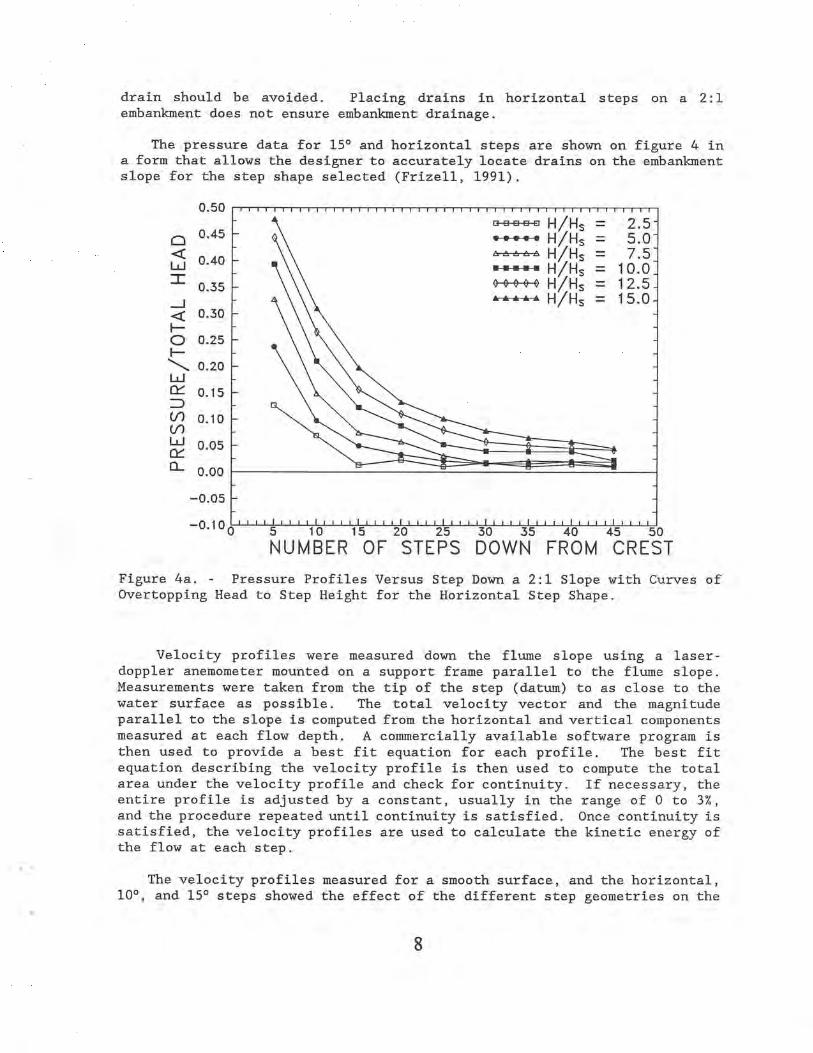
The pressure data for 15° and horizontal steps are shown on figure 4 in a form that allows the designer to accurately locate drains on the embankment slope for the step shape selected (Frizell, 1991).
0.50
0 0.45
Q 0.40 w = 0.35 J Q 0.30
O 0.25
0.20 W Cif 0.15
0 0.10 () n" 0.05
Cl- 0.00
~e~fl H/HS = 2.5 F•+♦ H/HS = 5.0
H/HS = 7.5 H ■ ■ H/HS = 10.0
H/HS = 12.5 H/HS = 15.0
0 5 10 15 20 25 30 35 40 45I-LI 50
NUMBER OF STEPS DOWN FROM CREST
Figure 4a. - Pressure Profiles Versus Step Down a 2:1 Slope with Curves of Overtopping Head to Step Height for the Horizontal Step Shape.
Velocity profiles were measured down the flume slope using a laser-doppler anemometer mounted on a support frame parallel to the flume slope. Measurements were taken from the tip of the step (datum) to as close to the water surface as possible. The total velocity vector and the magnitude parallel to the slope is computed from the horizontal and vertical components measured at each flow depth. A commercially available software program is then used to provide a best fit equation for each profile. The best fit equation describing the velocity profile is then used to compute the total area under the velocity profile and check for continuity. If necessary, the entire profile is adjusted by a constant, usually in the range of 0 to 3%, and the procedure repeated until continuity is satisfied. Once continuity is satisfied, the velocity profiles are used to calculate the kinetic energy of the flow at each step.
The velocity profiles measured for a smooth surface, and the horizontal, 10°, and 15° steps showed the effect of the different step geometries on the

0.40
p 0.35 a
LLJ 0.30
—I 0.25 Q
(D 0.20 O
0.15 W
CC 0.10
Cn (n 0.05 W 01-1
0.00 CL
—0.05
H/HS = 2.5 H/HS = 5.0 H/HS = 7.5
—= H/HS = 10.0 H / Hs = 12.5 H/HS = 15.0
0 5 10 15 20 25 30 35 40 45 50
NUMBER OF STEPS DOWN FROM CREST
Figure 4b. - Pressure Profiles Versus Step"Down a 2:1 Slope with Curves of Overtopping Head to Step Height for the 150 Step Shape.
resultant flow velocities. The measured velocities showed an increase in average velocity with an increase in tread slope (approaching a smooth surface). The most influence on the flow velocity was seen below a flow depth of 0.2 ft (0.06 m). This would be expected as the sloping steps do not interfere as much with the flow, particularly as the flow depth increases. Close to the steps the effect of the step geometry in reducing the flow velocity is quite apparent (Frizell, 1992).
The energy dissipation characteristics of the step geometries are compared by computing the kinetic energy per unit volume, 'hapV2, to the total head available, 7)(H+HS ), at each step location. The kinetic energy is calculated by integrating the area under the velocity profile and determining a, the coefficient of kinetic energy. The total head is calculated by adding the overtopping head, H, to the vertical drop from the crest to the step locatiton where the velocity measurement is taken, Hs, and multiplying by the specific weight of water, b.
Comparison of the kinetic energy remaining in the flow for smooth, horizontal, 10°, and 15° sloping steps shows the benefits of the step geometry in reducing the total energy available after the flow has travelled down the

slope for a given length. Note that the kinetic energy remaining in the flow increased as unit discharge increased for the smooth surface and all step geometries. The smooth surface spillway results show the flow is still accelerating, while the horizontal steps show the greatest reduction in energy. However, since the horizontal steps do not provide continuous aspiration of the subgrade flows a sloping step geometry must be chosen which will optimize aspiration and energy dissipation.
Aspiration may be assured by defining the limits of active aspiration in terms of unit discharge, embankment slope, step geometry, and step position down the embankment. The designer can identify aspiration limits of different step angles and determine the placement of drains. The designer then would conduct a stability analyses, including the hydraulic forces and the required thickness of material to assure a stable overlay. The aspirating step geometry will allow the designer to place less material over the embankment and still be assured of stability. Once a stable overlay is designed the step geometry can be optimized in terms of energy dissipation. The designer may then weigh the benefit of aspiration versus energy dissipation in determining the final step shape selection.
Designers may use the energy remaining in the flow for the step shape chosen to design a stilling basin or other protection at the dam toe. A reduced stilling basin length due to the reduced flow energy of a chosen step geometry represents a significant savings in construction time and money.
Continued Laboratory Testing
Testing has begun in Reclamation's laboratory flume of the optimum step geometry for a 4:1 slope. Pressure data have been gathered for horizontal steps and the next sloping step shape has been installed.
EMBANKMENT STABILITY
The most important feature of a stepped overlay on an embankment slope is that the underlying material of the dam remain stable. Saturation of the embankment may occur due to seepage through the overlay or by flow from the reservoir. An adequate drainage system should be utilized underneath the concrete overlay to prevent buildup of uplift pressures that may cause localized failure or general sliding of the embankment or overlay.
The recommended step design will provide continuous aspiration of subgrade flows through the overlay to prevent uplift pressures. Computer modeling of the tractive shear forces imposed on the overlay and embankment during flows is being developed.
10

Presently, of utmost concern with stepped spillway and overtopping designs is the location of embankment drains with respect to the tailwater and location of the hydraulic jump. Drains exiting the concrete overlay in the area of the hydraulic jump are subject to the dynamic pressures associated with the violent action of the jump. Care should be taken when locating drains in the stilling basins or toe of any stepped spillway or overtopping protection.
NEAR-PROTOTYPE TESTING
Reclamation is currently testing the step shape developed from our laboratory flume results in an outdoor, near-prototype size flume facility at Colorado State University in Fort Collins, Colorado. The near-prototype flume was constructed on a 2:1 slope with a drop of about 50 ft (15.2 m). The 5 foot (1.52 m) flume width will allow testing of unit discharges up to about 30 ft3/s/ft (0.85 m3/s/m) (figure 5).
Presently, individual sloping blocks, figure 6, with vents located on the vertical offset of the block are being tested in the flume. The blocks are placed, over a well graded angular filter material, shingle-fashion up the slope. Tests thus far have shown excellent promise. The overlapping blocks have withstood 23 ft3/s/ft (0.65 m3/s/m) discharges without failure and, in fact, no significant movement of the blocks. Results expected from the program include model/prototype correlations, velocities, flow depths, air concentration, and performance of the blocks under hydraulic jump conditions. Weather will hopefully permit continued testing this fall of the block stability underneath a hydraulic jump. The flume facility will be used to test other embankment overtopping protection methods including riprap and cable-tied blocks, upon completion of the testing of the sloping concrete blocks.
CONSTRUCTION TECHNIQUES
The stepped spillway research was initiated with the assumption that whatever shape proved to be most efficient from a hydraulic standpoint could be constructed in a continuous placement. This assumption puts no constraints on the shape of steps investigated but may produce some challenges for the construction contractors. The steps may be formed RCC, conventional concrete placed by slip forming or even reinforced concrete conventionally placed. Besides the step shape, the construction process must allow placement of drains or vents through the overlay to allow the aspiration produced by the step geometry as indicated by the drains shown on figure 3.
A joint effort is currently being investigated with a dam owner to construct continuously placed steps with drains on a dam in Massachusetts.
11

Figure 5. - Near-prototype Test Facility with Block Overtopping Protection Installed and a Discharge of 14.8 ft3/s/ft (4.5 m3/s/m).
This would prove the practicality and cost effectiveness of the technology and allows its expansion to general use for embankment dam overtopping protection.
;0161~10lk*3i1s1k'69
Early stepped spillway applications were on RCC dams with steep downstream slopes. The major benefits derived were ease of construction and energy dissipation, thus producing shorter stilling basins. These were generally high RCC dams with 2 foot step heights constructed with conventional concrete. The data available (presented on figure 1) to quantify the amount of energy dissipated by flow down these steep RCC dams can only provide general guidelines for sizing stilling basins due to the great amount of scatter. Present Reclamation research will improve our ability to predict step spillway energy dissipation.
12

Figure 6. - Block Shape Developed from Laboratory Testing that is being Used in the Near-prototype Studies (1" — 25.4 mm).
The emphasis of present research has been on producing a stable stepped spillway overlay, that still provides energy dissipation, on 2:1 embankment dam slopes. The results reported in this paper show excellent promise toward achieving this end. The sloping step geometry will provide aspiration of seepage necessary for stability. The steps on a 2:1 slope, while not dissipating as much energy as the steep concrete dam slopes, due provide advantages over a traditional smooth surface spillway.
After the step geometry is finalized for a 2:1 slope the placement of drains through the formed overlay will be the next challenge. It appears that present forming and consolidation techniques could be modified to accommodate the required step geometry.
REFERENCES
Clopper, P. E., "Hydraulic Stability of Articulated Concrete Block Revetment Systems During Overtopping Flow" Report No. FHWA-RD-89-199, Federal Highway Administration, Washington D.C., November 1989.
Frizell, K. H., "Final Model Study Results for Milltown Hill Dam Spillway and Stilling Basin," U. S. Bureau of Reclamation, Denver, Colorado, August 22, 1990.
Houston, Kathleen L., "Hydraulic Model Studies of Upper Stillwater Dam Stepped Spillway and Outlet Works," REC-ERC-87-6, Bureau of Reclamation, Denver, Colorado, October 1987.
13
Jordaan, J. M., "De Mist Kraal Weir Energy Dissipation Model Study," Q800/08/DH03, Department of Water Affairs, Pretoria 0001, Republic of South Africa, May, 1986.
Pravdivets, Y. P. and M. E. Bramley, "Stepped Protection Blocks for Dam Spillways," Water Power and Dam Construction, Vol. 41, No. 7, July 1989, pp 60-6.6.
Sorenson, Robert M., "Stepped Spillway Hydraulic Model Investigation," Journal of Hydraulic Engineering, ASCE, Vol. III, No. 12, December, 1985, pp. 1461-1472.
Stevens, Michael A., "Stagecoach Dam and Reservoir Project - Model Spillway Report." Memorandum Report, P.O. Box 3263, Boulder, Colorado.
Frizell, K. Warren and H. Peck, "Hydraulic Model Studies of the Upstream Dam Jequitai River Development Project," U.S. Bureau of Reclamation, Denver, CO, August 1992.
Frizell, Kathleen H., "Hydraulic Design of Stepped Concrete Overtopping Protection for Embankment Dams," Proceedings of the Association of State Dams Safety Officials Annual Conference, San Diego, CA, September 1991.
Frizell, K. H., "Hydraulics of Stepped Spillways for RCC Dams and Dam Rehabilitations," Proceedings of the ASCE Roller Compacted Concrete III Conference, San Diego, CA, February 1992.
14