stellram expanded milling catalog - metricsteelcam.org/каталоги/stellram... · 5 hard case:...
TRANSCRIPT

CUTTING TOOLSStellram® Cutting Tools
HIGH PERFORMANCE MILLING SOLUTIONS
KMST-009_ExpFocusBroMetricUK_Cov-20.indd 3 4/25/14 4:13 PM
Заказ инструмента: http://steelcam.org | 8 (343) 382-52-03 | [email protected]

www.kennametal.comC
Patented Breakthroughs for Difficult to Machine Materials: Cut Faster. Cut Longer. Cut More Profitably.
These Kennametal Milling Systems are specifically designed and manufactured for machining high performance, difficult-to-machine materials.
This capability was developed after years of advanced R&D in materials science and machining Titanium and Titanium Alloys, Nickel Alloys and Superalloys, Stainless Steel and Specialty Alloys, and Hard Materials.
The result: These proven “Best in Class” machining solutions presented in this brochure.
Our strategy is to bring “game changing” cutting tool solutions that deliver industry leading metal removal rates. Higher metal removal rates mean you increase capacity, make more profit and deliver in shorter lead times.
Stellram® high performance cutting tools are known for cutting titanium like butter and have found wide application in the aerospace, defense, power generation, oil and gas, medical, transportation and construction and mining industries.
KMST-009_ExpFocusBroMetricUK_Cov-20.indd 3 4/25/14 4:13 PM
Заказ инструмента: http://steelcam.org | 8 (343) 382-52-03 | [email protected]

www.kennametal.com 1
Page
Application Guide ................................................................................................................................................................................................................... 2
Patented X-Grade Insert Technology ..................................................................................................................................................................................... 2
7792 Patented High Feed Milling
Introduction ......................................................................................................................................................................................................... 3 - 5
7792VXP06 Series .............................................................................................................................................................................................. 6 - 7
7792VXD 09 | 12 Series .................................................................................................................................................................................... 8 - 11
7792VXE16 Series .......................................................................................................................................................................................... 12 - 13
7792VX Speeds, Technical & Case Histories ................................................................................................................................................... 14 - 18
7792 Geometries & Grades ............................................................................................................................................................................. 19 - 20
The 77 Family
Introduction ..................................................................................................................................................................................................... 21 - 23
7700VR08 Series ............................................................................................................................................................................................ 24 - 28
7710VRD20 Series .......................................................................................................................................................................................... 30 - 35
7713VR 10 | 12 Series .................................................................................................................................................................................... 36 - 44
Tungsten Shank ...................................................................................................................................................................................................... 45
7700 Geometries & Grades ............................................................................................................................................................................. 46 - 47
5230 Chevron Long Edge Milling
Introduction ..................................................................................................................................................................................................... 49 - 51
5230VS 90 | 12 Series .................................................................................................................................................................................... 52 - 62
5230 Geometries & Grades ..................................................................................................................................................................................... 63
5505 Ball Nose Contour Mills
Introduction ..................................................................................................................................................................................................... 65 - 67
5505 Series ...................................................................................................................................................................................................... 68 -72
Case Histories | Geometries & Grades ..................................................................................................................................................................... 73
Tungsten Shanks ..................................................................................................................................................................................................... 74
5720 Profile Pocket Milling: Aluminium
Introduction ..................................................................................................................................................................................................... 75 - 77
5720VZ16 Series ............................................................................................................................................................................................ 78 - 83
Case Histories | Geometries & Grades ..................................................................................................................................................................... 84
5702 High Speed Aluminium Cutters
Introduction ..................................................................................................................................................................................................... 85 - 87
Geometries & Grades .............................................................................................................................................................................................. 87
5702VZD14 Series .......................................................................................................................................................................................... 88 - 92
Metalcutting Safety .............................................................................................................................................................................................................. 93
KMST-009_ExpFocusBroMetricUK_Cov-20.indd 1 4/25/14 4:13 PM
Заказ инструмента: http://steelcam.org | 8 (343) 382-52-03 | [email protected]

www.kennametal.com2
Application Guide
Patented X-Grade Insert Technology
Helical Interpolation
Spiral/Circular
Slot/Shoulder
Shoulder/Profile
Shoulder/Profile/Slot
Helical Interpolationwith Bore Hole
Copy / 3DContour Face
Plunge
TrochoidalT-Slot
RampPocket
Full Ø Plunge
Chamfer
3-TIMES THE METAL REMOVAL RATE
Titanium and Nickel Based Alloys are some of the toughest machining jobs on earth.
And it is a rare element, a member of the platinum family, called Ruthenium, that is one
of the key ingredients used in our patented X-Grade™ Technology cutting tools.
We combine Ruthenium with Cobalt to form an exclusive binder that cements our
engineered carbide formulas in the making of these inserts. X-Grade Inserts provide unmatched performance in cutting difficult to machine materials.
Application Guide
KMST-009_ExpFocusBroMetricUK_Cov-20.indd 2 4/25/14 4:13 PM
Заказ инструмента: http://steelcam.org | 8 (343) 382-52-03 | [email protected]

www.kennametal.com 3
7792 High Feed Milling
• Patented Cutter Designs• Patented Insert Designs• Patented Grades
To remove the highest volume of metal in the shortest possible time
KMST-009_ExpFocusBroMetricUK_Cov-20.indd 3 4/25/14 4:13 PM
Заказ инструмента: http://steelcam.org | 8 (343) 382-52-03 | [email protected]

www.kennametal.com4
7792: Increase Metal Removal Rate up to 90% or More!
The Patented 7792 Insert
• Cutting diameters from 16mm to 160mm
• Modular, Weldon, Cylindrical and Shell Mill cutter configurations
• Modular Tungsten Extensions maintain stability in deep pocket applications
• All inserts feature 4 cutting edges
The unique 7792 insert design provides outstanding operational security and performance, with enhanced metal removal capability.
• Maximize tool life, versatility and performance
• Face, Pocket, Shoulder, Profile, Helical Interpolate, Ramp, Copy and Mill Turn with one tool
• 6 grades for materials from Aluminium to Superalloys
• 4 insert sizes available
• Depth of cut from 0,90mm to 3,50mm
• Coarse, medium and fine pitch cutters available for all machining conditions.
Modular16mm – 32mm
Weldon25mm – 32mm
Cylindrical16mm – 32mm
Shell40mm – 160mm
7792 Patented High Feed Milling
KMST-009_ExpFocusBroMetricUK_Cov-20.indd 4 4/25/14 4:13 PM
Заказ инструмента: http://steelcam.org | 8 (343) 382-52-03 | [email protected]
www.kennametal.com 5
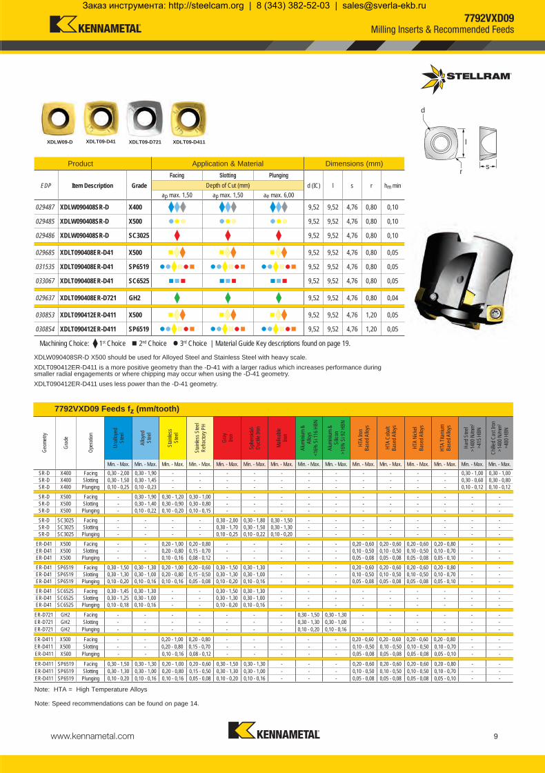
Hard Case: The Ti Alpha Barrier
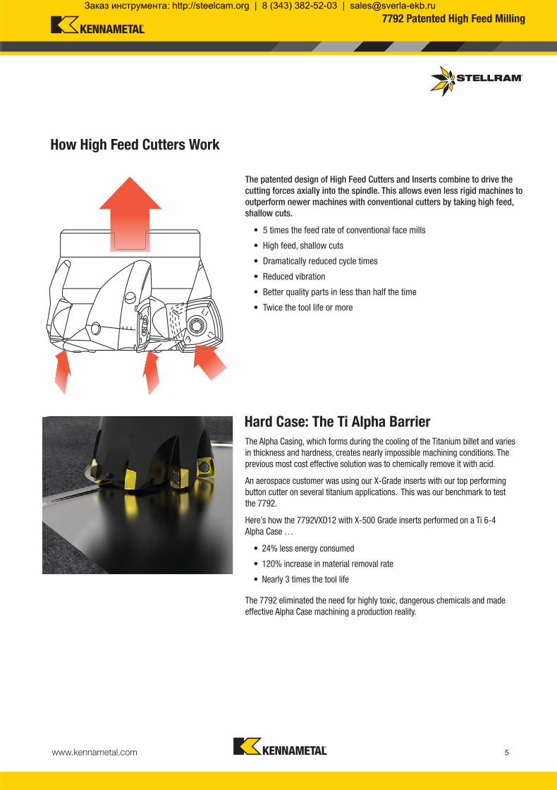
How High Feed Cutters Work
The Alpha Casing, which forms during the cooling of the Titanium billet and varies in thickness and hardness, creates nearly impossible machining conditions. The previous most cost effective solution was to chemically remove it with acid.
An aerospace customer was using our X-Grade inserts with our top performing button cutter on several titanium applications. This was our benchmark to test the 7792.
Here’s how the 7792VXD12 with X-500 Grade inserts performed on a Ti 6-4 Alpha Case …
• 24% less energy consumed
• 120% increase in material removal rate
• Nearly 3 times the tool life
The 7792 eliminated the need for highly toxic, dangerous chemicals and made effective Alpha Case machining a production reality.
The patented design of High Feed Cutters and Inserts combine to drive the cutting forces axially into the spindle. This allows even less rigid machines to outperform newer machines with conventional cutters by taking high feed, shallow cuts. • 5 times the feed rate of conventional face mills
• High feed, shallow cuts
• Dramatically reduced cycle times
• Reduced vibration
• Better quality parts in less than half the time
• Twice the tool life or more
7792 Patented High Feed Milling
KMST-009_ExpFocusBroMetricUK_Cov-20.indd 5 4/25/14 4:13 PM
Заказ инструмента: http://steelcam.org | 8 (343) 382-52-03 | [email protected]

www.kennametal.com6
A B
031632 7792VXP06SA016Z2R25 16 25 M8 8,50 0,90 2 031449 FP2506T 031452 TP7 1,00031633 7792VXP06SA020Z2R35 20 35 M10 10,50 0,90 2 031449 FP2506T 031452 TP7 1,00031634 7792VXP06SA020Z3R35 20 35 M10 10,50 0,90 3 031449 FP2506T 031452 TP7 1,00031636 7792VXP06SA025Z3R35 25 35 M12 12,50 0,90 3 031450 FP2507T 031452 TP7 1,00031637 7792VXP06SA025Z4R35 25 35 M12 12,50 0,90 4 031450 FP2507T 031452 TP7 1,00031638 7792VXP06SA032Z5R43 32 43 M16 17,00 0,90 5 031450 FP2507T 031452 TP7 1,00
031644 7792VXP06CA016Z2R140 16 188 25 16 0,90 2 031449 FP2506T 031452 TP7 1,00031629 7792VXP06CA020Z3R154 20 204 32 20 0,90 3 031449 FP2506T 031452 TP7 1,00031630 7792VXP06CA025Z4R154 25 210 40 25 0,90 4 031450 FP2507T 031452 TP7 1,00031631 7792VXP06CA032Z5R190 32 250 40 32 0,90 5 031450 FP2507T 031452 TP7 1,00
031644 7792VXP06CA016Z2R140 7,60 5.94 8.03 22 30 0,60 3,00 65000031629 7792VXP06CA020Z3R154 11,60 3.42 6.12 30 38 0,60 3,00 57000031630 7792VXP06CA025Z4R154 16,60 2.23 4.24 40 48 0,60 3,00 49000031631 7792VXP06CA032Z5R190 23,60 1.39 2.60 54 62 0,60 3,00 41500031632 7792VXP06SA016Z2R25 7,60 5.94 8.03 22 30 0,60 3,00 65000031633 7792VXP06SA020Z2R35 11,60 3.42 6.12 30 38 0,60 3,00 57000031634 7792VXP06SA020Z3R35 11,60 3.42 6.12 30 38 0,60 3,00 57000031636 7792VXP06SA025Z3R35 16,60 2.84 4.24 40 48 0,60 3,00 49000031637 7792VXP06SA025Z4R35 16,60 2.23 4.24 40 48 0,60 3,00 49000031638 7792VXP06SA032Z5R43 23,60 1.39 2.60 54 62 0,60 3,00 41500
M
L
D
D
L
I1
d1
d1
ap
7792VXP06 Technical Information (mm)
Product Dimensions
EDP Item Description Facing Pitch
Ramping Angle Helical Hole
min. - max.ap max Helical /Linear
ae max Plunging
Max RPMA ° B °
Note: For cylindrical shank extensions in high density alloy with through coolant refer to page 45.
Product Dimensions (mm) Spares
EDP Item Description D L/H l1 d1 ap max No. of Teeth EDP EDP
ScrewTightening
Nm
Product Dimensions (mm) Spares
EDP Item Description D L/H M d1 ap max No. of Teeth EDP EDP
ScrewTightening
Nm
7792VXP06 Cylindrical Shank
7792VXP06 Modular Head - Medium and Fine Pitch
Flat
Facing Pitch
Helical Interpolation
Plunging
Ramp angle B uses two cutting edges (one outside and one inside edge).
Ramp angle A uses one outside cutting edge only.
A = max ramp angle utilising full face contact
B = max ramp angle utilising full contact + internal corner radiusDepth of Cut (ap)
Cylindrical Shank
Modular Head
7792VXP06High Feed Milling Cutter
KMST-009_ExpFocusBroMetricUK_Cov-20.indd 6 4/25/14 4:13 PM
Заказ инструмента: http://steelcam.org | 8 (343) 382-52-03 | [email protected]

www.kennametal.com 7
030403 XPLT060308ER-D41 X400 7,00 7,00 3,18 0,80 0,04
030402 XPLT060308ER-D41 X500 7,00 7,00 3,18 0,80 0,04
031538 XPLT060308ER-D41 SP6519 7,00 7,00 3,18 0,80 0,04
033066 XPLT060308ER-D41 SC6525 7,00 7,00 3,18 0,80 0,04
ER-D41 X400 0,20 - 1,10 0,20 - 0,90 - - - - - - - - - - - 0,20 - 0,60 0,20 - 0,60ER-D41 X400 0,20 - 0,90 0,20 - 0,80 - - - - - - - - - - - 0,20 - 0,50 0,20 - 0,50ER-D41 X400 0,04 - 0,30 0,04 - 0,20 - - - - - - - - - - - 0,04 - 0,08 0,04 - 0,08
ER-D41 X500 - - 0,15 - 1,00 0,15 - 0,90 - - - - - 0,15 - 0,50 0,15 - 0,50 0,15 - 0,50 0,15 - 0,60 - -ER-D41 X500 - - 0,15 - 0,80 0,15 - 0,75 - - - - - 0,10 - 0,40 0,10 - 0,40 0,10 - 0,40 0,10 - 0,45 - -ER-D41 X500 - - 0,04 - 0,20 0,04 - 0,15 - - - - - 0,04 - 0,06 0,04 - 0,06 0,04 - 0,06 0,04 - 0,06 - -
ER-D41 SP6519 0,20 - 1,00 0,20 - 0,80 0,15 - 0,90 0,15 - 0,80 0,20 - 1,20 0,20 - 1,00 0,20 - 0,90 0,20 - 0,70 - 0,15 - 0,50 0,15 - 0,50 0,15 - 0,50 0,15 - 0,60 - -ER-D41 SP6519 0,20 - 0,80 0,20 - 0,75 0,15 - 0,80 0,15 - 0,70 0,20 - 1,00 0,20 - 0,90 0,20 - 0,80 0,20 - 0,70 - 0,10 - 0,40 0,10 - 0,40 0,10 - 0,40 0,10 - 0,45 - -ER-D41 SP6519 0,04 - 0,25 0,04 - 0,18 0,04 - 0,20 0,04 - 0,14 0,04 - 0,25 0,04 - 0,20 0,04 - 0,18 0,04 - 0,25 - 0,04 - 0,06 0,04 - 0,06 0,04 - 0,06 0,04 - 0,06 - -
ER-D41 SC6525 0,20 - 0,95 0,20 - 0,78 - - 0,20 - 1,20 0,20 - 1,00 - - - - - - - - -ER-D41 SC6525 0,20 - 0,78 0,20 - 0,72 - - 0,20 - 1,00 0,20 - 0,90 - - - - - - - - -ER-D41 SC6525 0,04 - 0,23 0,04 - 0,17 - - 0,04 - 0,25 0,04 - 0,20 - - - - - - - - -
XPLT06-D41
d
l
rs
Note: Speed recommendations can be found on page 14.
Product Application & Material Dimensions (mm)
EDP Item Description GradeFacing Slotting Plunging
d (IC) l s r hm minDepth of Cut (mm)ap max. 0,90 ap max. 0,90 ae max. 3,00
Note: HTA = High Temperature Alloys
FacingSlottingPlunging
FacingSlottingPlunging
FacingSlottingPlunging
FacingSlottingPlunging
7792VXP06 Feeds fz (mm/tooth)
Geom
etry
Grad
e
Oper
ation
Unall
oyed
St
eel
Alloy
ed
Stee
l
Stain
less
Stee
l
Stain
less S
teel
Refra
ctory
PH
Gray
Iro
n
Sphe
roida
l- Du
ctile
Iron
Malle
able
Iron
Alum
inium
&
Alloy
s <1
6% S
i 116
HBN
Alum
inium
&
Silic
on
>16
% S
i 92 H
BN
HTA
Iron
Base
d Allo
ys
HTA
Coba
lt Ba
sed A
lloys
HTA
Nick
elBa
sed A
lloys
HTA
Titan
ium
Base
d Allo
ys
Hard
Stee
l>1
400 N
/mm2
>415
HBN
Chille
d Cas
t Iron
>140
0 N/m
m2
>400
HBN
Min. - Max. Min. - Max. Min. - Max. Min. - Max. Min. - Max. Min. - Max. Min. - Max. Min. - Max. Min. - Max. Min. - Max. Min. - Max. Min. - Max. Min. - Max. Min. - Max. Min. - Max.
Machining Choice: 1st Choice 2nd Choice 3rd Choice | Material Guide Key descriptions found on page 19.
7792VXP06Milling Inserts & Recommended Feeds
KMST-009_ExpFocusBroMetricUK_Cov-20.indd 7 4/25/14 4:13 PM
Заказ инструмента: http://steelcam.org | 8 (343) 382-52-03 | [email protected]

www.kennametal.com8
030613 7792VXD09SA025Z2R35 25 35 M12 12,50 1,50 2 015269 F3508T 015240 T15 2,10030614 7792VXD09SA032Z3R43 32 43 M16 17,00 1,50 3 015064 F3510T 015240 T15 2,10
029461 7792VXD09WA025Z2R 25 96 40 25 1,50 2 015269 F3508T 015240 T15 2,10029462 7792VXD09WA032Z3R 32 100 40 32 1,50 3 015064 F3510T 015240 T15 2,10
031191 7792VXD09CA025Z2R50 25 200 50 25 1,50 2 015064 F3510T 015240 T15 2,10031192 7792VXD09CA032Z3R70 32 250 70 32 1,50 3 015064 F3510T 015240 T15 2,10 029463 7792VXD09-A040Z3R 40 32 - 16 1,50 3 015064 F3510T 015240 T15 2,10029464 7792VXD09-A040Z4R 40 32 - 16 1,50 4 015064 F3510T 015240 T15 2,10030434 7792VXD09-A040Z5R 40 32 - 16 1,50 5 015064 F3510T 015240 T15 2,10030435 7792VXD09-A050Z5R 50 40 - 22 1,50 5 015064 F3510T 015240 T15 2,10030436 7792VXD09-A050Z6R 50 40 - 22 1,50 6 015064 F3510T 015240 T15 2,10
d1
H
D
D
L
I1
d1
D
L
I1
d1
D
029461 7792VXD09WA025Z2R 11,75 2.80 6.30 34 48 1,00 6,00 48500029462 7792VXD09WA032Z3R 18,75 1.50 5.00 48 62 1,00 6,00 40500031191 7792VXD09CA025Z2R50 11,75 2.80 6.30 34 48 1,00 6,00 48500031192 7792VXD09CA032Z3R70 18,75 1.50 5.00 48 62 1,00 6,00 40500029463 7792VXD09-A040Z3R 26,75 0.80 2.70 64 78 1,00 6,00 34500029464 7792VXD09-A040Z4R 26,75 0.80 2.70 64 78 1,00 6,00 34500030434 7792VXD09-A040Z5R 26,75 0.80 2.70 64 78 1,00 6,00 34500030435 7792VXD09-A050Z5R 36,75 0.71 2.31 84 98 1,00 6,00 30000030436 7792VXD09-A050Z6R 36,75 0.71 2.31 84 98 1,00 6,00 29500030613 7792VXD09SA025Z2R35 11,75 2.80 6.30 34 48 1,00 6,00 48500030614 7792VXD09SA032Z3R43 18,75 1.50 5.00 48 62 1,00 6,00 40500
M
L
D
d1
ap
A B
7792VXD09 Technical Information (mm)
Product Dimensions
EDP Item Description Facing Pitch
Ramping Angle Helical Hole
min. - max.ap max Helical /Linear
ae max Plunging
Max RPMA ° B °
Product Dimensions (mm) Spares
EDP Item Description D L/H M d1 ap max No. of Teeth EDP EDP
ScrewTightening
Nm
Product Dimensions (mm) Spares
EDP Item Description D L/H l1 d1 ap max No. of Teeth EDP EDP
ScrewTightening
Nm
7792VXD09 Weldon Shank
7792VXD09 Cylindrical Shank
7792VXD09 Shell Mill Fixation - Coarse, Medium and Fine Pitch
7792VXD09 Modular Head
Ramp angle B uses two cutting edges (one outside and one inside edge).
Ramp angle A uses one outside cutting edge only.
A = max ramp angle utilising full face contact
B = max ramp angle utilising full contact + internal corner radiusDepth of Cut (ap)
Modular Head
Cylindrical Shank
Weldon Shank
Shell Mill Fixation
7792VXD09High Feed Milling Cutter
Flat
Facing Pitch
Helical Interpolation
Plunging
Note: For cylindrical shank extensions in high density alloy with through coolant refer to page 45.
KMST-009_ExpFocusBroMetricUK_Cov-20.indd 8 4/25/14 4:16 PM
Заказ инструмента: http://steelcam.org | 8 (343) 382-52-03 | [email protected]
www.kennametal.com 9
SR-D X400 0,30 - 2,00 0,30 - 1,90 - - - - - - - - - - - 0,30 - 1,00 0,30 - 1,00SR-D X400 0,30 - 1,50 0,30 - 1,45 - - - - - - - - - - - 0,30 - 0,60 0,30 - 0,80SR-D X400 0,10 - 0,25 0,10 - 0,23 - - - - - - - - - - - 0,10 - 0,12 0,10 - 0,12
SR-D X500 - 0,30 - 1,90 0,30 - 1,20 0,30 - 1,00 - - - - - - - - - - -SR-D X500 - 0,30 - 1,40 0,30 - 0,90 0,30 - 0,80 - - - - - - - - - - -SR-D X500 - 0,10 - 0,22 0,10 - 0,20 0,10 - 0,15 - - - - - - - - - - -
SR-D SC3025 - - - - 0,30 - 2,00 0,30 - 1,80 0,30 - 1,50 - - - - - - - -SR-D SC3025 - - - - 0,30 - 1,70 0,30 - 1,50 0,30 - 1,30 - - - - - - - -SR-D SC3025 - - - - 0,10 - 0,25 0,10 - 0,22 0,10 - 0,20 - - - - - - - -
ER-D41 X500 - - 0,20 - 1,00 0,20 - 0,80 - - - - - 0,20 - 0,60 0,20 - 0,60 0,20 - 0,60 0,20 - 0,80 - -ER-D41 X500 - - 0,20 - 0,80 0,15 - 0,70 - - - - - 0,10 - 0,50 0,10 - 0,50 0,10 - 0,50 0,10 - 0,70 - -ER-D41 X500 - - 0,10 - 0,16 0,08 - 0,12 - - - - - 0,05 - 0,08 0,05 - 0,08 0,05 - 0,08 0,05 - 0,10 - -
ER-D41 SP6519 0,30 - 1,50 0,30 - 1,30 0,20 - 1,00 0,20 - 0,60 0,30 - 1,50 0,30 - 1,30 - - - 0,20 - 0,60 0,20 - 0,60 0,20 - 0,60 0,20 - 0,80 - -ER-D41 SP6519 0,30 - 1,30 0,30 - 1,00 0,20 - 0,80 0,15 - 0,50 0,30 - 1,30 0,30 - 1,00 - - - 0,10 - 0,50 0,10 - 0,50 0,10 - 0,50 0,10 - 0,70 - -ER-D41 SP6519 0,10 - 0,20 0,10 - 0,16 0,10 - 0,16 0,05 - 0,08 0,10 - 0,20 0,10 - 0,16 - - - 0,05 - 0,08 0,05 - 0,08 0,05 - 0,08 0,05 - 0,10 - -
ER-D41 SC6525 0,30 - 1,45 0,30 - 1,30 - - 0,30 - 1,50 0,30 - 1,30 - - - - - - - - -ER-D41 SC6525 0,30 - 1,25 0,30 - 1,00 - - 0,30 - 1,30 0,30 - 1,00 - - - - - - - - -ER-D41 SC6525 0,10 - 0,18 0,10 - 0,16 - - 0,10 - 0,20 0,10 - 0,16 - - - - - - - - -
ER-D721 GH2 - - - - - - - 0,30 - 1,50 0,30 - 1,30 - - - - - -ER-D721 GH2 - - - - - - - 0,30 - 1,30 0,30 - 1,00 - - - - - -ER-D721 GH2 - - - - - - - 0,10 - 0,20 0,10 - 0,16 - - - - - -
ER-D411 X500 - - 0,20 - 1,00 0,20 - 0,80 - - - - - 0,20 - 0,60 0,20 - 0,60 0,20 - 0,60 0,20 - 0,80 - -ER-D411 X500 - - 0,20 - 0,80 0,15 - 0,70 - - - - - 0,10 - 0,50 0,10 - 0,50 0,10 - 0,50 0,10 - 0,70 - -ER-D411 X500 - - 0,10 - 0,16 0,08 - 0,12 - - - - - 0,05 - 0,08 0,05 - 0,08 0,05 - 0,08 0,05 - 0,10 - -
ER-D411 SP6519 0,30 - 1,50 0,30 - 1,30 0,20 - 1,00 0,20 - 0,60 0,30 - 1,50 0,30 - 1,30 - - - 0,20 - 0,60 0,20 - 0,60 0,20 - 0,60 0,20 - 0,80 - -ER-D411 SP6519 0,30 - 1,30 0,30 - 1,00 0,20 - 0,80 0,15 - 0,50 0,30 - 1,30 0,30 - 1,00 - - - 0,10 - 0,50 0,10 - 0,50 0,10 - 0,50 0,10 - 0,70 - -ER-D411 SP6519 0,10 - 0,20 0,10 - 0,16 0,10 - 0,16 0,05 - 0,08 0,10 - 0,20 0,10 - 0,16 - - - 0,05 - 0,08 0,05 - 0,08 0,05 - 0,08 0,05 - 0,10 - -
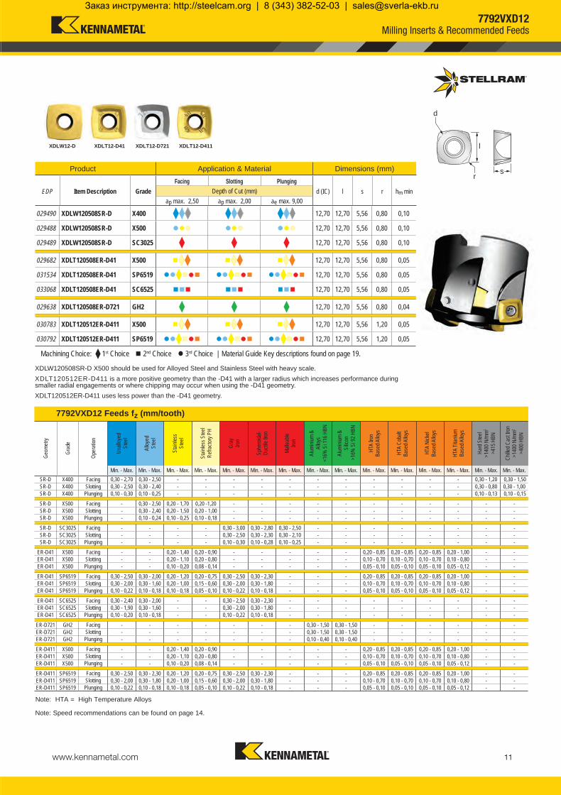
029487 XDLW090408SR-D X400 9,52 9,52 4,76 0,80 0,10
029485 XDLW090408SR-D X500 9,52 9,52 4,76 0,80 0,10
029486 XDLW090408SR-D SC3025 9,52 9,52 4,76 0,80 0,10
029685 XDLT090408ER-D41 X500 9,52 9,52 4,76 0,80 0,05
031535 XDLT090408ER-D41 SP6519 9,52 9,52 4,76 0,80 0,05
033067 XDLT090408ER-D41 SC6525 9,52 9,52 4,76 0,80 0,05
029637 XDLT090408ER-D721 GH2 9,52 9,52 4,76 0,80 0,04
030853 XDLT090412ER-D411 X500 9,52 9,52 4,76 1,20 0,05
030854 XDLT090412ER-D411 SP6519 9,52 9,52 4,76 1,20 0,05
XDLW09-D XDLT09-D41 XDLT09-D721 XDLT09-D411
d
l
rsProduct Application & Material Dimensions (mm)
EDP Item Description GradeFacing Slotting Plunging
d (IC) l s r hm minDepth of Cut (mm)ap max. 1,50 ap max. 1,50 ae max. 6,00
7792VXD09 Feeds fz (mm/tooth)
Geom
etry
Grad
e
Oper
ation
Unall
oyed
St
eel
Alloy
ed
Stee
l
Stain
less
Stee
l
Stain
less S
teel
Refra
ctory
PH
Gray
Iro
n
Sphe
roida
l- Du
ctile
Iron
Malle
able
Iron
Alum
inium
&
Alloy
s <1
6% S
i 116
HBN
Alum
inium
&
Silic
on
>16
% S
i 92 H
BN
HTA
Iron
Base
d Allo
ys
HTA
Coba
lt Ba
sed A
lloys
HTA
Nick
elBa
sed A
lloys
HTA
Titan
ium
Base
d Allo
ys
Hard
Stee
l>1
400 N
/mm2
>415
HBN
Chille
d Cas
t Iron
>140
0 N/m
m2
>400
HBN
Min. - Max. Min. - Max. Min. - Max. Min. - Max. Min. - Max. Min. - Max. Min. - Max. Min. - Max. Min. - Max. Min. - Max. Min. - Max. Min. - Max. Min. - Max. Min. - Max. Min. - Max.
Note: HTA = High Temperature Alloys
FacingSlottingPlunging
FacingSlottingPlunging
FacingSlottingPlunging
FacingSlottingPlunging
FacingSlottingPlunging
FacingSlottingPlunging
FacingSlottingPlunging
FacingSlottingPlunging
FacingSlottingPlunging
Machining Choice: 1st Choice 2nd Choice 3rd Choice | Material Guide Key descriptions found on page 19.
Note: Speed recommendations can be found on page 14.
XDLW090408SR-D X500 should be used for Alloyed Steel and Stainless Steel with heavy scale. XDLT090412ER-D411 is a more positive geometry than the -D-41 with a larger radius which increases performance during smaller radial engagements or where chipping may occur when using the -D-41 geometry. XDLT090412ER-D411 uses less power than the -D-41 geometry.
7792VXD09Milling Inserts & Recommended Feeds
KMST-009_ExpFocusBroMetricUK_Cov-20.indd 9 4/25/14 4:17 PM
Заказ инструмента: http://steelcam.org | 8 (343) 382-52-03 | [email protected]

www.kennametal.com10
030994 7792VXD12SA032Z2R43 32 43 M16 17,00 2,50 2 015262 D4010T 015240 T15 3,10
031195 7792VXD12CA032Z2R70 32 250 70 32 2,50 2 015262 D4010T 015240 T15 3,10 029467 7792VXD12-A052Z3R 52 40 - 22 2,50 3 015263 D4012T 015240 T15 3,10029468 7792VXD12-A052Z4R 52 40 - 22 2,50 4 015263 D4012T 015240 T15 3,10030489 7792VXD12-A052Z5R 52 40 - 22 2,50 5 015262 D4010T 015240 T15 3,10029469 7792VXD12-A063Z4R 63 40 - 22 2,50 4 015263 D4012T 015240 T15 3,10029470 7792VXD12-A063Z5R 63 40 - 22 2,50 5 015263 D4012T 015240 T15 3,10031650 7792VXD12-A066Z4R 66 45 - 27 2,50 4 015263 D4012T 015240 T15 3,10031651 7792VXD12-A066Z5R 66 45 - 27 2,50 5 015263 D4012T 015240 T15 3,10029471 7792VXD12-A080Z5R 80 50 - 27 2,50 5 015263 D4012T 015240 T15 3,10030490 7792VXD12-A080Z8R 80 50 - 27 2,50 8 015263 D4012T 015240 T15 3,10030443 7792VXD12-A100Z6R 100 50 - 32 2,50 6 015263 D4012T 015240 T15 3,10030444 7792VXD12-A100Z9R 100 50 - 32 2,50 9 015263 D4012T 015240 T15 3,10030445 7792VXD12-A125Z8R 125 63 - 40 2,50 8 015263 D4012T 015240 T15 3,10030446 7792VXD12-A125Z11R 125 63 - 40 2,50 11 015263 D4012T 015240 T15 3,10033216 7792VXD12-160Z07R 160 63 40 2.50 7 015263 D4012T 015240 T15 3,10
d1
H
D
D
L
I1
d1
031195 7792VXD12CA032Z2R70 10,60 1.80 2.60 42 62 1,80 9,00 31500029467 7792VXD12-A052Z3R 33,60 0.80 2.70 82 102 1,80 9,00 22000029468 7792VXD12-A052Z4R 33,60 0.80 2.70 82 102 1,80 9,00 22000030489 7792VXD12-A052Z5R 33,60 0.80 2.70 82 102 1,80 9,00 22000029469 7792VXD12-A063Z4R 44,60 0.60 1.80 104 124 1,80 9,00 19500029470 7792VXD12-A063Z5R 44,60 0.60 1.80 104 124 1,80 9,00 19500031650 7792VXD12-A066Z4R 47,60 0.45 1.80 110 130 1,80 9,00 19000031651 7792VXD12-A066Z5R 47,60 0.45 1.80 110 130 1,80 9,00 19000029471 7792VXD12-A080Z5R 61,60 0.45 0.90 138 158 1,80 9,00 17000030490 7792VXD12-A080Z8R 61,60 0.45 0.90 138 158 1,80 9,00 17000030443 7792VXD12-A100Z6R 81,60 0.32 1.45 178 198 1,80 9,00 15000030444 7792VXD12-A100Z9R 81,60 0.32 1.45 178 198 1,80 9,00 15000030445 7792VXD12-A125Z8R 106,60 0.24 1.06 228 248 1,80 9,00 13000030446 7792VXD12-A125Z11R 106,60 0.24 1.06 228 248 1,80 9,00 13000033216 7792VXD12-160Z07R 141,60 0.20 0.86 298 318 1,80 9,00 11500030994 7792VXD12SA032Z2R43 10,60 1.80 2.60 42 62 1,80 9,00 31500
M
L
D
d1
ap
A B
7792VXD12 Technical Information (mm)
Product Dimensions
EDP Item Description Facing Pitch
Ramping Angle Helical Hole
min. - max.ap max Helical /Linear
ae max Plunging
Max RPMA ° B °
Note: For cylindrical shank extensions in high density alloy with through coolant refer to page 45.
Product Dimensions (mm) Spares
EDP Item Description D L/H M d1 ap max No. of Teeth EDP EDP
ScrewTightening
Nm
Product Dimensions (mm) Spares
EDP Item Description D L/H l1 d1 ap max No. of Teeth EDP EDP
ScrewTightening
Nm
7792VXD12 Cylindrical Shank
7792VXD12 Shell Mill Fixation - Coarse, Medium and Fine Pitch
7792VXD12 Modular Head
Depth of Cut (ap)
Modular Head
Cylindrical Shank
Shell Mill Fixation
7792VXD12 High Feed Milling Cutter
A = max ramp angle utilizing full face contact
B = max ramp angle utilizing full contact + internal corner radius
Ramp angle A uses one outside cutting edge only.
Facing Pitch
Flat
Ramp angle B uses two cutting edges (one outside and one inside edge).
Helical Interpolation
Plunging
KMST-009_ExpFocusBroMetricUK_Cov-20.indd 10 4/25/14 4:18 PM
Заказ инструмента: http://steelcam.org | 8 (343) 382-52-03 | [email protected]
www.kennametal.com 11
SR-D X400 0,30 - 2,70 0,30 - 2,50 - - - - - - - - - - - 0,30 - 1,20 0,30 - 1,50SR-D X400 0,30 - 2,50 0,30 - 2,40 - - - - - - - - - - - 0,30 - 0,80 0,30 - 1,00SR-D X400 0,10 - 0,30 0,10 - 0,25 - - - - - - - - - - - 0,10 - 0,13 0,10 - 0,15
SR-D X500 - 0,30 - 2,50 0,20 - 1,70 0,20 -1,20 - - - - - - - - - - -SR-D X500 - 0,30 - 2,40 0,20 - 1,50 0,20 - 1,00 - - - - - - - - - - -SR-D X500 - 0,10 - 0,24 0,10 - 0,25 0,10 - 0,18 - - - - - - - - - - -
SR-D SC3025 - - - - 0,30 - 3,00 0,30 - 2,80 0,30 - 2,50 - - - - - - - -SR-D SC3025 - - - - 0,30 - 2,50 0,30 - 2,30 0,30 - 2,10 - - - - - - - -SR-D SC3025 - - - - 0,10 - 0,30 0,10 - 0,28 0,10 - 0,25 - - - - - - - -
ER-D41 X500 - - 0,20 - 1,40 0,20 - 0,90 - - - - - 0,20 - 0,85 0,20 - 0,85 0,20 - 0,85 0,20 - 1,00 - -ER-D41 X500 - - 0,20 - 1,10 0,20 - 0,80 - - - - - 0,10 - 0,70 0,10 - 0,70 0,10 - 0,70 0,10 - 0,80 - -ER-D41 X500 - - 0,10 - 0,20 0,08 - 0,14 - - - - - 0,05 - 0,10 0,05 - 0,10 0,05 - 0,10 0,05 - 0,12 - -
ER-D41 SP6519 0,30 - 2,50 0,30 - 2,00 0,20 - 1,20 0,20 - 0,75 0,30 - 2,50 0,30 - 2,30 - - - 0,20 - 0,85 0,20 - 0,85 0,20 - 0,85 0,20 - 1,00 - -ER-D41 SP6519 0,30 - 2,00 0,30 - 1,60 0,20 - 1,00 0,15 - 0,60 0,30 - 2,00 0,30 - 1,80 - - - 0,10 - 0,70 0,10 - 0,70 0,10 - 0,70 0,10 - 0,80 - -ER-D41 SP6519 0,10 - 0,22 0,10 - 0,18 0,10 - 0,18 0,05 - 0,10 0,10 - 0,22 0,10 - 0,18 - - - 0,05 - 0,10 0,05 - 0,10 0,05 - 0,10 0,05 - 0,12 - -
ER-D41 SC6525 0,30 - 2,40 0,30 - 2,00 - - 0,30 - 2,50 0,30 - 2,30 - - - - - - - - -ER-D41 SC6525 0,30 - 1,90 0,30 - 1,60 - - 0,30 - 2,00 0,30 - 1,80 - - - - - - - - -ER-D41 SC6525 0,10 - 0,20 0,10 - 0,18 - - 0,10 - 0,22 0,10 - 0,18 - - - - - - - - -
ER-D721 GH2 - - - - - - - 0,30 - 1,50 0,30 - 1,50 - - - - - -ER-D721 GH2 - - - - - - - 0,30 - 1,50 0,30 - 1,50 - - - - - -ER-D721 GH2 - - - - - - - 0,10 - 0,40 0,10 - 0,40 - - - - - -
ER-D411 X500 - - 0,20 - 1,40 0,20 - 0,90 - - - - - 0,20 - 0,85 0,20 - 0,85 0,20 - 0,85 0,20 - 1,00 - -ER-D411 X500 - - 0,20 - 1,10 0,20 - 0,80 - - - - - 0,10 - 0,70 0,10 - 0,70 0,10 - 0,70 0,10 - 0,80 - -ER-D411 X500 - - 0,10 - 0,20 0,08 - 0,14 - - - - - 0,05 - 0,10 0,05 - 0,10 0,05 - 0,10 0,05 - 0,12 - -
ER-D411 SP6519 0,30 - 2,50 0,30 - 2,30 0,20 - 1,20 0,20 - 0,75 0,30 - 2,50 0,30 - 2,30 - - - 0,20 - 0,85 0,20 - 0,85 0,20 - 0,85 0,20 - 1,00 - -ER-D411 SP6519 0,30 - 2,00 0,30 - 1,80 0,20 - 1,00 0,15 - 0,60 0,30 - 2,00 0,30 - 1,80 - - - 0,10 - 0,70 0,10 - 0,70 0,10 - 0,70 0,10 - 0,80 - -ER-D411 SP6519 0,10 - 0,22 0,10 - 0,18 0,10 - 0,18 0,05 - 0,10 0,10 - 0,22 0,10 - 0,18 - - - 0,05 - 0,10 0,05 - 0,10 0,05 - 0,10 0,05 - 0,12 - -
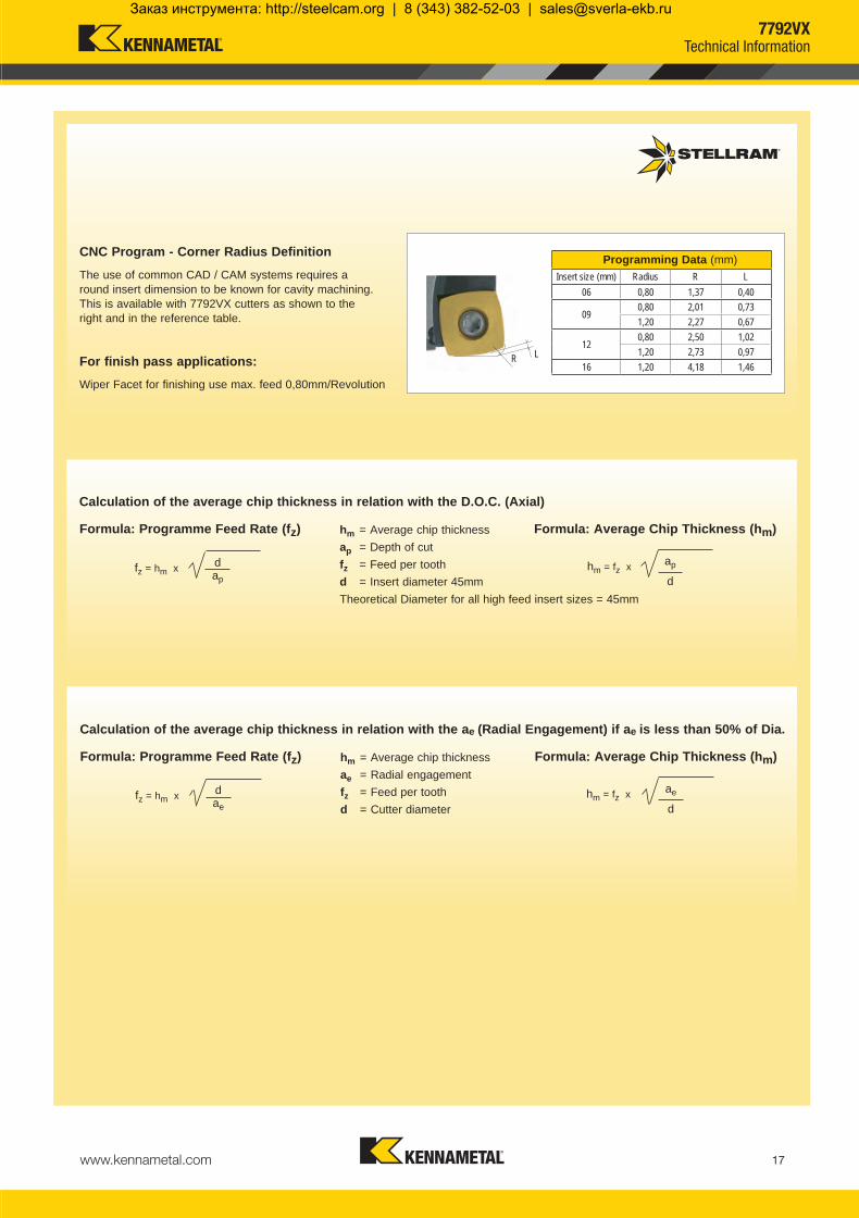
029490 XDLW120508SR-D X400 12,70 12,70 5,56 0,80 0,10
029488 XDLW120508SR-D X500 12,70 12,70 5,56 0,80 0,10
029489 XDLW120508SR-D SC3025 12,70 12,70 5,56 0,80 0,10
029682 XDLT120508ER-D41 X500 12,70 12,70 5,56 0,80 0,05
031534 XDLT120508ER-D41 SP6519 12,70 12,70 5,56 0,80 0,05
033068 XDLT120508ER-D41 SC6525 12,70 12,70 5,56 0,80 0,05
029638 XDLT120508ER-D721 GH2 12,70 12,70 5,56 0,80 0,04
030783 XDLT120512ER-D411 X500 12,70 12,70 5,56 1,20 0,05
030792 XDLT120512ER-D411 SP6519 12,70 12,70 5,56 1,20 0,05
XDLW12-D XDLT12-D41 XDLT12-D721 XDLT12-D411
d
l
rs
Machining Choice: 1st Choice 2nd Choice 3rd Choice | Material Guide Key descriptions found on page 19.
Product Application & Material Dimensions (mm)
EDP Item Description GradeFacing Slotting Plunging
d (IC) l s r hm minDepth of Cut (mm)ap max. 2,50 ap max. 2,00 ae max. 9,00
7792VXD12 Feeds fz (mm/tooth)
Geom
etry
Grad
e
Oper
ation
Unall
oyed
St
eel
Alloy
ed
Stee
l
Stain
less
Stee
l
Stain
less S
teel
Refra
ctory
PH
Gray
Iro
n
Sphe
roida
l- Du
ctile
Iron
Malle
able
Iron
Alum
inium
&
Alloy
s <1
6% S
i 116
HBN
Alum
inium
&
Silic
on
>16
% S
i 92 H
BN
HTA
Iron
Base
d Allo
ys
HTA
Coba
lt Ba
sed A
lloys
HTA
Nick
elBa
sed A
lloys
HTA
Titan
ium
Base
d Allo
ys
Hard
Stee
l>1
400 N
/mm2
>415
HBN
Chille
d Cas
t Iron
>140
0 N/m
m2
>400
HBN
Min. - Max. Min. - Max. Min. - Max. Min. - Max. Min. - Max. Min. - Max. Min. - Max. Min. - Max. Min. - Max. Min. - Max. Min. - Max. Min. - Max. Min. - Max. Min. - Max. Min. - Max.
Note: HTA = High Temperature Alloys
FacingSlottingPlunging
FacingSlottingPlunging
FacingSlottingPlunging
FacingSlottingPlunging
FacingSlottingPlunging
FacingSlottingPlunging
FacingSlottingPlunging
FacingSlottingPlunging
FacingSlottingPlunging
Note: Speed recommendations can be found on page 14.
XDLW120508SR-D X500 should be used for Alloyed Steel and Stainless Steel with heavy scale. XDLT120512ER-D411 is a more positive geometry than the -D41 with a larger radius which increases performance during smaller radial engagements or where chipping may occur when using the -D41 geometry. XDLT120512ER-D411 uses less power than the -D41 geometry.
7792VXD12Milling Inserts & Recommended Feeds
KMST-009_ExpFocusBroMetricUK_Cov-20.indd 11 4/25/14 4:18 PM
Заказ инструмента: http://steelcam.org | 8 (343) 382-52-03 | [email protected]

www.kennametal.com12
034851 7792VXE16CA040Z2R102 40 172 102 40 3,50 2 031225 DP5013T 030819 TP20 6,10034852 7792VXE16CA050Z3R102 50 172 102 40 3,50 3 031225 DP5013T 030819 TP20 6,10 031277 7792VXE16-A063Z5R 63 40 - 22 3,50 5 031225 DP5013T 030819 TP20 6,10031278 7792VXE16-A080Z6R 80 50 - 27 3,50 6 031225 DP5013T 030819 TP20 6,10031279 7792VXE16-A100Z8R 100 50 - 32 3,50 8 031225 DP5013T 030819 TP20 6,10031280 7792VXE16-A125Z10R 125 63 - 40 3,50 10 031225 DP5013T 030819 TP20 6,10031281 7792VXE16-160Z12 160 63 - 40 3,50 12 031225 DP5013T 030819 TP20 6,10
d1
H
D
034851 7792VXE16CA040Z2R102 16,10 2.55 3.35 50 78 2.50 13.00 33000034852 7792VXE16CA050Z3R102 25,83 1.36 2.85 70 98 2.50 13.00 27500031277 7792VXE16-A063Z5R 37,45 0.86 1.00 96 124 2.50 13,00 22000031278 7792VXE16-A080Z6R 54,45 0.58 0.65 130 158 2.50 13,00 19000031279 7792VXE16-A100Z8R 74,45 0.42 0.51 170 198 2.50 13,00 16500031280 7792VXE16-A125Z10R 99,45 0.32 0.37 220 248 2.50 13,00 14500031281 7792VXE16-160Z12 134,50 0.23 0.27 290 318 2.50 13,00 12500
ap
A B
D
L
I1
d1
7792VXE16 Technical Information (mm)
Product Dimensions
EDP Item Description Facing Pitch
Ramping Angle Helical Hole
min. - max.ap max Helical /Linear
ae max Plunging
Max RPMA ° B °
Product Dimensions (mm) Spares
EDP Item Description D L/H l1 d1 ap max No. of Teeth EDP EDP
ScrewTightening
Nm
Depth of Cut (ap)
Shell Mill Fixation
Ramp angle B uses two cutting edges (one outside and one inside edge).
Flat
Facing Pitch
Ramp angle A uses one outside cutting edge only.
A = max ramp angle utilising full face contact
B = max ramp angle utilising full contact + internal corner radius
7792VXE16High Feed Milling Cutter
Helical Interpolation
Plunging
7792VXE16 Cylindrcal Shank
7792VXE16 Shell Mill FixationCylindrical Shank
KMST-009_ExpFocusBroMetricUK_Cov-20.indd 12 4/25/14 4:19 PM
Заказ инструмента: http://steelcam.org | 8 (343) 382-52-03 | [email protected]

www.kennametal.com 13
SR-D X400 0,30 - 2,00 0,30 - 1,80 - - - - - - - - - - - 0,30 - 0,80 0,30 - 1,00SR-D X400 0,30 - 1,70 0,30 - 1,50 - - - - - - - - - - - 0,30 - 0,50 0,30 - 0,60SR-D X400 0,10 - 0,27 0,10 - 0,22 - - - - - - - - - - - 0,10 - 0,10 0,10 - 0,12
SR-D SC3025 - - - - 0,30 - 2,00 0,30 - 1,80 0,30 - 1,50 - - - - - - - -SR-D SC3025 - - - - 0,30 - 1,50 0,30 - 1,30 0,30 - 1,20 - - - - - - - -SR-D SC3025 - - - - 0,10 - 0,20 0,10 - 0,18 0,10 - 0,15 - - - - - - - -
ER-D41 X500 - - 0,20 - 1,00 0,20 - 0,60 - - - - - 0,20 - 0,60 0,20 - 0,60 0,20 - 0,60 0,20 - 0,80 - -ER-D41 X500 - - 0,20 - 0,80 0,20 - 0,50 - - - - - 0,10 - 0,40 0,10 - 0,40 0,10 - 0,40 0,10 - 0,50 - -ER-D41 X500 - - 0,12 - 0,16 0,07 - 0,13 - - - - - 0,05 - 0,10 0,05 - 0,10 0,05 - 0,10 0,05 - 0,12 - -
ER-D41 SP6519 0,30 - 1,50 0,30 - 1,30 0,20 - 1,00 0,20 - 0,50 0,30 - 1,50 0,30 - 1,20 - - - 0,20 - 0,60 0,20 - 0,60 0,20 - 0,60 0,20 - 0,80 - -ER-D41 SP6519 0,30 - 1,30 0,30 - 1,20 0,20 - 0,80 0,20 - 0,45 0,30 - 1,20 0,30 - 1,10 - - - 0,10 - 0,40 0,10 - 0,40 0,10 - 0,40 0,10 - 0,50 - -ER-D41 SP6519 0,10 - 0,23 0,10 - 0,20 0,12 - 0,16 0,07 - 0,12 0,10 - 0,20 0,10 - 0,16 - - - 0,05 - 0,10 0,05 - 0,10 0,05 - 0,10 0,05 - 0,12 - -
ER-D41 SC6525 0,30 - 1,40 0,30 - 1,20 - - 0,30 - 1,50 0,30 - 1,20 - - - - - - - - -ER-D41 SC6525 0,30 - 1,20 0,30 - 1,10 - - 0,30 - 1,20 0,30 - 1,10 - - - - - - - - -ER-D41 SC6525 0,10 - 0,20 0,10 - 0,18 - - 0,10 - 0,20 0,10 - 0,16 - - - - - - - - -
031291 XELW160512SR-D X400 16,80 16,80 5,56 1,20 0,12
031292 XELW160512SR-D SC3025 16,80 16,80 5,56 1,20 0,12
031293 XELT160512ER-D41 X500 16,80 16,80 5,56 1,20 0,12
031294 XELT160512ER-D41 SP6519 16,80 16,80 5,56 1,20 0,12
033069 XELT160512ER-D41 SC6525 16,80 16,80 5,56 1,20 0,12
XELW16-D XELT16-D41
d
l
rsProduct Application & Material Dimensions (mm)
EDP Item Description GradeFacing Slotting Plunging
d (IC) l s r hm minDepth of Cut (mm)ap max. 3,50 ap max. 3,00 ae max.13,00
7792VXE16 Feeds fz (mm/tooth)
Geom
etry
Grad
e
Oper
ation
Unall
oyed
St
eel
Alloy
ed
Stee
l
Stain
less
Stee
l
Stain
less S
teel
Refra
ctory
PH
Gray
Iro
n
Sphe
roida
l- Du
ctile
Iron
Malle
able
Iron
Alum
inium
&
Alloy
s <1
6% S
i 116
HBN
Alum
inium
&
Silic
on
>16
% S
i 92 H
BN
HTA
Iron
Base
d Allo
ys
HTA
Coba
lt Ba
sed A
lloys
HTA
Nick
elBa
sed A
lloys
HTA
Titan
ium
Base
d Allo
ys
Hard
Stee
l>1
400 N
/mm2
>415
HBN
Chille
d Cas
t Iron
>140
0 N/m
m2
>400
HBN
Min. - Max. Min. - Max. Min. - Max. Min. - Max. Min. - Max. Min. - Max. Min. - Max. Min. - Max. Min. - Max. Min. - Max. Min. - Max. Min. - Max. Min. - Max. Min. - Max. Min. - Max.
Note: HTA = High Temperature Alloys
FacingSlottingPlunging
FacingSlottingPlunging
FacingSlottingPlunging
FacingSlottingPlunging
FacingSlottingPlunging
Machining Choice: 1st Choice 2nd Choice 3rd Choice | Material Guide Key descriptions found on page 19.
Note: Speed recommendations can be found on page 14.
7792VXE16Milling Inserts & Recommended Feeds
KMST-009_ExpFocusBroMetricUK_Cov-20.indd 13 4/25/14 4:19 PM
Заказ инструмента: http://steelcam.org | 8 (343) 382-52-03 | [email protected]

www.kennametal.com14
P
120 - 260
130 - 295
140 - 370
105 - 230 115 - 260 120 - 325
95 - 200
100 - 210
100 - 230
105 - 290
70 - 150 75 - 160 75 - 175 80 - 210
45 - 95 50 - 100 50 - 110 50 - 140
-- +
M
115 - 250
115 - 270
100 - 220 105 - 235
50 - 110 50 - 120
K
140 - 295
145 - 390
150 - 395
110 - 240 115 - 305 120 - 335
100 - 220 105 - 275
N
305 - 2130
400 - 2745
245 - 1760 295 - 2135
S
23 - 48
23 - 55
21 - 44 22 - 48
24 - 51 25 - 55
35 - 73 36 - 79
H
45 - 95
35 - 80
Recommended Possible
Speed vc (m/min)
7792VX SeriesWear Resistance
Speed min. - max.
Coolant Recommendation PVDX Grade
CVDX Grade
PVDStandard
Uncoated Micrograin
CVDStandard
CVDStandard
ISO Materials Rm and Hardness X400 X500 SP6519 GH2 SC6525 SC3025
UnalloyedSteel
<600 N/mm2
<180 HBN<950 N/mm2
<280 HBN
AlloyedSteel
700-950 N/mm2
200-280 HBN950-1200 N/mm2
280-355 HBN1200-1400 N/mm2
355-415 HBN
StainlessSteel
Austenitic + Ferritic300 seriesMartensitic400 series
PH Stainless RefractoryP.H.
Cast Iron
GreyGG-Ft
Spheroidal-DuctileGGG-FGSMalleable
GTS - MN/MP
Aluminium & Alloys
Aluminium & Alloys < 16% Si 116 HBN
Aluminium + Silicon > 16% Si 92 HBN
HighTemperature
Alloys
Iron Based
Cobalt Based
Nickel Based
Titanium Based
Hard Materials
Hard Steel>1400 N/mm2
>415 HBNChilled Cast Iron
>1400 N/mm2 > 400 HBN
7792VXRecommended Speeds
KMST-009_ExpFocusBroMetricUK_Cov-20.indd 14 4/25/14 4:19 PM
Заказ инструмента: http://steelcam.org | 8 (343) 382-52-03 | [email protected]

www.kennametal.com 15
7792VXP06 7792VXD09 7792VXD12 7792VXE1616 20 25 32 25 32 40 50 32 52 63 66 80 100 125 160 63 80 100 125 1606 6 6 6 9 9 9 9 12 12 12 12 12 12 12 12 16 16 16 16 163 3 3 3 6 6 6 6 9 9 9 9 9 9 9 9 13 13 13 13 13
0,25 3,97 4,44 4,97 5,63 4,97 5,63 6,30 7,05 5,63 7,19 7,92 8,11 8,93 9,99 11,17 12,64 7,92 8,93 9,99 11,17 12,640,50 5,57 6,24 7,00 7,94 7,00 7,94 8,89 9,95 7,94 10,15 11,18 11,44 12,61 14,11 15,78 17,86 11,18 12,61 14,11 15,78 17,860,75 6,76 7,60 8,53 9,68 8,53 9,68 10,85 12,16 9,68 12,40 13,67 13,99 15,42 17,26 19,31 21,86 13,67 15,42 17,26 19,31 21,861,00 7,75 8,72 9,80 11,14 9,80 11,14 12,49 14,00 11,14 14,28 15,75 16,12 17,78 19,90 22,27 25,22 15,75 17,78 19,90 22,27 25,222,00 10,58 12,00 13,56 15,49 13,56 15,49 17,44 19,60 15,49 20,00 22,09 22,63 24,98 28,00 31,37 35,55 22,09 24,98 28,00 31,37 35,553,00 12,49 14,28 16,25 18,65 16,25 18,65 21,07 23,75 18,65 24,25 26,83 27,49 30,40 34,12 38,26 43,41 26,83 30,40 34,12 38,26 43,414,00 18,33 21,17 24,00 27,13 21,17 27,71 30,72 31,50 34,87 39,19 44,00 49,96 30,72 34,87 39,19 44,00 49,965,00 20,00 23,24 26,46 30,00 23,24 30,66 34,06 34,93 38,73 43,59 48,99 55,68 34,06 38,73 43,59 48,99 55,686,00 21,35 24,98 28,57 32,49 24,98 33,23 36,99 37,95 42,14 47,50 53,44 60,79 36,99 42,14 47,50 53,44 60,797,00 26,46 35,50 39,60 40,64 45,21 51,03 57,48 65,45 39,60 45,21 51,03 57,48 65,458,00 27,71 37,52 41,95 43,08 48,00 54,26 61,19 69,74 41,95 48,00 54,26 61,19 69,749,00 28,77 39,34 44,09 45,30 50,56 57,24 64,62 73,73 44,09 50,56 57,24 64,62 73,7310,00 46,04 52,92 60,00 67,82 77,4611,00 47,83 55,10 62,58 70,82 80,9712,00 49,48 57,13 64,99 73,65 84,2913,00 50,99 59,03 67,26 76,32 87,43
0616 7,6020 11,6025 16,6032 23,60
0925 11,7532 18,7540 26,7550 36,75
12
32 10,6052 33,6063 44,6066 47,6080 61,60100 81,60125 106,60160 141,60
16
63 37,4580 54,45100 74,45125 99,45160 134,50
0616 22 3020 30 3825 40 4832 54 62
0925 34 4832 48 6240 64 7850 84 98
12
32 42 6252 82 10263 104 12466 110 13080 138 158
100 178 198125 228 248160 298 318
16
63 96 12480 130 158
100 170 198125 220 248160 290 318
Helical interpolation capacity for 7792VX (mm)Insert Size Cutter dia. Hole min. Hole max.
Max. flat surface (mm)Insert size Cutter dia. Pitch
Plunging Information (mm) tool definition-scallop height and step over Tool definition (mm)
DiameterInsert size
ae maxScallop height Step over (mm)
Tool
InsertWorkpiece
ae (Maximum)
Scallop Height
Stepover
Plunging
The cutting edge should not be in contact with the material face after machining to maintain the cutting edge quality.
The scallop height is calculated in relation to the step over.
The maximum radial engagement is directly in relation to insert cutting edge length.
For insert type: XP…06 the ae, max is 3mm.For insert type: XD…09 the ae, max is 6mm.For insert type: XD…12 the ae, max is 9mm.For insert type: XE…16 the ae, max is 13mm.
7792VXTechnical Information
Helical Interpolation
Facing Pitch
Flat
KMST-009_ExpFocusBroMetricUK_Cov-20.indd 15 4/25/14 4:19 PM
Заказ инструмента: http://steelcam.org | 8 (343) 382-52-03 | [email protected]

www.kennametal.com16
Round insert
• Greater surface contact.
• Increased chip section for side wall machining.
• Vibration in corners.
• Undulating side wall cusps.
7792VX • Constant cutting section (chip volume) irrespective of position in cavity.
• Producing a close to profile side wall.
• Near-square side walls possible.
The 7792VX machines with a constant volume of chip throughout all aspects of producing cavities and produces a side wall that is close to profile.
Round insert tools have increasing chip volume through the process.
Round Insert Tools • Tangential
forces act around the radius
• Leads to vibration and damage of the cutting edge
• Leads to reduced feed and lower productivity
7792VX • Cutting forces predominantly axial
• Relationship between cutting edge and work piece is at its most stable.
• Results in high feed rates and consistent tool life.
The advantages of face milling and producing cavities with Stellram’s high feed face mill are numerous. The unique design of the insert, approach angle and the cutter body ensure the cutting forces are predominantly directed in the axial direction. The example shown with a round insert tool shows complex forces which result in high levels of vibration and damage to the cutting edge.
Centre clearance Side wall
7792VXTechnical Information
KMST-009_ExpFocusBroMetricUK_Cov-20.indd 16 4/25/14 4:19 PM
Заказ инструмента: http://steelcam.org | 8 (343) 382-52-03 | [email protected]
www.kennametal.com 17
06 0,80 1,37 0,40
090,80 2,01 0,731,20 2,27 0,67
120,80 2,50 1,021,20 2,73 0,97
16 1,20 4,18 1,46LR
Programming Data (mm)Insert size (mm) Radius R L
hm = fz x fz = hm x
hm = fz x fz = hm x
Calculation of the average chip thickness in relation with the ae (Radial Engagement) if ae is less than 50% of Dia.
Calculation of the average chip thickness in relation with the D.O.C. (Axial)
CNC Program - Corner Radius Definition
The use of common CAD / CAM systems requires a round insert dimension to be known for cavity machining. This is available with 7792VX cutters as shown to the right and in the reference table.
Formula: Average Chip Thickness (hm)hm = Average chip thicknessae = Radial engagementfz = Feed per toothd = Cutter diameter
Formula: Programme Feed Rate (fz)
Formula: Average Chip Thickness (hm)hm = Average chip thicknessap = Depth of cutfz = Feed per toothd = Insert diameter 45mmTheoretical Diameter for all high feed insert sizes = 45mm
Formula: Programme Feed Rate (fz)
For finish pass applications: Wiper Facet for finishing use max. feed 0,80mm/Revolution
ae
ddae
ap
ddap
7792VXTechnical Information
KMST-009_ExpFocusBroMetricUK_Cov-20.indd 17 4/25/14 4:19 PM
Заказ инструмента: http://steelcam.org | 8 (343) 382-52-03 | [email protected]

www.kennametal.com18
7792 Case Histories
Material: 4140 steel – 280 - 320 HBN Industry: Die/MoldJob: 17 holes – 51,59mm diameter, 67,74mm deepCycle time: 4.5 hours
7792 Solution:Cutter: Modular 7792VXD09 (25mm Cutter)Extension: Anti-vibration, heavy-alloy Modular Shank Insert Grade: X400 Process: High Feed Helical InterpolationCycle time: 1 minute 45 seconds per holeTotal Cycle time: 30 minutes
90% Reduction in Cycle Time
Material: 6-4 TitaniumJob: Machine pockets in aerospace componentCycle time: 5.5 hours
7792 Solution:Cutter: 7792VXD12 (160mm Cutter)Insert Grade: X500 Cycle time: 1 hour 20 minutes
75% Reduction in Cycle Time
Material: 6-4 TitaniumJob: Turn a 1463mm diameter by 340mm deep ringIndustry: AerospaceTurning Cycle time: 4 hours 35 minutes
7792 Solution:Cutter: 7792VXE16 (125mm Cutter)Insert Grade: X500 Process: Mill turning Workpiece rotates on B axis at 0,26 RPM Spiral milling feed rate of 60mm per revolutionCycle time: 2 hours 24 minutes
Spiral Milling Cuts Cycle Time 48%
7792 Case Histories
KMST-009_ExpFocusBroMetricUK_Cov-20.indd 18 4/25/14 4:19 PM
Заказ инструмента: http://steelcam.org | 8 (343) 382-52-03 | [email protected]

www.kennametal.com 19
P P M M K N S H
P P K H
M M S
N
M M S
Material Guide – Key to Recommended InsertsMaterial Designation
Alloyed Steels PH Stainless Aluminum & Alloys High Temp. Alloys Hard MaterialsUnalloyed Steels Stainless Steels Cast Irons
High Feed Geometries
-D
-D41
-D411
-D721
Fully ground with flat top and variable hone. Hardened Materials up to 480HBN.
Positive geometry that reduces power consumption.
Positive geometry with larger corner radius (1,2mm) reduces cutting energy and provides better edge protection during lower radial engagement applications.
Positive, periphery ground, polished top rake face and sharp edge allows a freer cutting action and reduces built-up edge.
7792 Patented High Feed Milling
KMST-009_ExpFocusBroMetricUK_Cov-20.indd 19 4/25/14 4:19 PM
Заказ инструмента: http://steelcam.org | 8 (343) 382-52-03 | [email protected]

www.kennametal.com20
P P M M K N S H
High Feed Grades
K
N
P P H
M S
M
KP P
Material Guide – Key to Recommended InsertsMaterial Designation
Alloyed Steels PH Stainless Aluminum & Alloys High Temp. Alloys Hard MaterialsUnalloyed Steels Stainless Steels Cast Irons
Coating Type: PVD, TiAlN – Super nano coating is extremely hard for unmatched performance and virtually eliminates residual stress.
GH2
X500
SC3025
SC6525
SP6519
X400
Coating Type: CVD, TiN-TiC-TiN – High level of shock resistance; operates at low to medium cutting speeds; high metal removal rates.
Coating Type: CVD, TiN - TiCN - Al2O3 – Multi-layer CVD coating offers wear and abrasion resistance.
Coating Type: CVD, TiN-TiCN-Al2O3 – High Performance Machining at elevated surface speeds.
Uncoated Micrograin – Tough and able to handle high pressure, vibration and shock.
Coating Type: PVD, TiAlN – Designed for high metal removal rates and interrupted cuts.
High Feed Grades
KMST-009_ExpFocusBroMetricUK_Cov-20.indd 20 4/25/14 4:19 PM
Заказ инструмента: http://steelcam.org | 8 (343) 382-52-03 | [email protected]

www.kennametal.com 21
The 77 Family
• Patented Cutter Designs• Patented Insert Designs• Patented Grades
Excellent for roughing, semi-finishing and finishing of high-performance materials
KMST-009_ExpFocusBroMetricUK_21-47.indd 21 4/25/14 4:26 PM
Заказ инструмента: http://steelcam.org | 8 (343) 382-52-03 | [email protected]

www.kennametal.com22
The 77 Family
Three Families of Cutters are Featured: • 7700VR08 small diameter standard button cutters (Cylindrical, Weldon and Modular: 16mm to 32mm)
• 7710VRD20 Anti-Rotation Shell Mill cutters (63mm to 160mm)
• 7713VR10 and 12 Patented Anti-Rotation Cutters (Cylindrical, Modular and Shell: 20mm to 80mm)
This collection of cutters shows the dynamics of Kennametal technology—taking the conventional to the highest level to machine the toughest high performance alloys.
Continuous Cutting Under the Toughest Conditions • Cutter diameters from 16mm to 160mm
• Maximum number of teeth for heavy feed operations
• Medium and close pitch cutters available
• Round button insert for maximum strength
• 8mm to 20mm insert diameters
• Low cutting forces
• Flute design maximizes chip evacuation
• Satin Silver coating extends cutter body life (only 7713VR series)
• Modular tools feature an Anti-Vibration Tungsten Extension with Through Coolant
Shell40mm – 160mm
Modular16mm – 40mm
Cylindrical16mm – 32mm
Weldon25mm
77 Family
KMST-009_ExpFocusBroMetricUK_21-47.indd 22 4/25/14 4:26 PM
Заказ инструмента: http://steelcam.org | 8 (343) 382-52-03 | [email protected]

www.kennametal.com 23
VRD / VR Anti-Rotation Technology
The High Flute Indexing CutterThe 7710 and 7713 series cutters feature a unique patented pocket system that locks the inserts into position to prevent inserts from moving during heavy machining.
• Through Coolant and unique flow through pocket design maximise chip evacuation and increase tool life
7713 Patented series cutter bodies are armored with Satin Silver plating to protect body integrity in milling high performance materials.
The Positive Indexing Round InsertThe Anti-Rotation insert features four, five or eight locking positions which mate with the pocket of the cutter body.
• Positive positioning of the insert throughout the heaviest cuts
• Maximum indexes to optimize tool life and reduce tooling costs
Maximum Chip Evacuation
Maximum Tool Life
Heavy Cut Geometries
Locking Positions
High Flute Design
Through Tool Coolant
77 Family
KMST-009_ExpFocusBroMetricUK_21-47.indd 23 4/25/14 4:26 PM
Заказ инструмента: http://steelcam.org | 8 (343) 382-52-03 | [email protected]

www.kennametal.com24
021732 7700VR08WA025R070-M3 25 17 126 70 25 4 3 015062 F3006T 013214 T9 1,40021733 7700VR08WA025R124-M3 25 17 180 124 25 4 3 015062 F3006T 013214 T9 1,40 031134 7700VR08CA020Z3R40 20 12 180 40 20 4 3 015062 F3006T 013214 T9 1,40031135 7700VR08CA025Z3R50 25 17 200 50 25 4 3 015062 F3006T 013214 T9 1,40031602 7700VR08CA025Z4R50 25 17 200 50 25 4 4 015062 F3006T 013214 T9 1,40031137 7700VR08CA032Z4R70 32 24 250 70 32 4 4 015062 F3006T 013214 T9 1,40031081 7700VR08CA032Z5R70 32 24 250 70 32 4 5 015062 F3006T 013214 T9 1,40
M
L
d1
ap
031124 7700VR08SA016Z2R25 16 8 25 M8 8.5 4 2 015062 F3006T 013214 T9 1,40031125 7700VR08SA020Z3R25 20 12 25 M10 10.5 4 3 015062 F3006T 013214 T9 1,40031126 7700VR08SA025Z3R35 25 17 35 M12 12.5 4 3 015062 F3006T 013214 T9 1,40031127 7700VR08SA025Z4R35 25 17 35 M12 12.5 4 4 015062 F3006T 013214 T9 1,40031080 7700VR08SA032Z5R35 32 24 35 M16 17.0 4 5 015062 F3006T 013214 T9 1,40
021732 7700VR08WA025R070-M3 17 7.85 36 48 2,67 68000021733 7700VR08WA025R124-M3 17 7.85 36 48 2,67 68000031134 7700VR08CA020Z3R40 12 9.10 26 38 2,67 81000031135 7700VR08CA025Z3R50 17 7.85 36 48 2,67 68000031602 7700VR08CA025Z4R50 17 7.85 36 48 2,67 68000031137 7700VR08CA032Z4R70 24 6.75 50 62 2,67 57000031081 7700VR08CA032Z5R70 24 6.75 50 62 2,67 57000031124 7700VR08SA016Z2R25 8 32.60 18 30 2,67 99000031125 7700VR08SA020Z3R25 12 12.70 26 38 2,67 81000031126 7700VR08SA025Z3R35 17 7.85 36 48 2,67 68000031127 7700VR08SA025Z4R35 17 7.85 36 48 2,67 68000031080 7700VR08SA032Z5R35 24 7.20 50 62 2,67 57000
L
d1
I1
L
I1
d1
Da*D
Da*D
Da*D
D = Effective Diameter (Axis) from insert centreline to centreline.
D = Effective Diameter (Axis) from insert centreline to centreline.
7700VR08 Technical Information (mm)
Product Dimensions
EDP Item Description Facing Pitch
Ramping Angle °
Helical Hole min. - max.
ap max Helical /Linear
Max RPM
7700VR08 Modular Head - Medium and Fine Pitch
Product Dimensions (mm) Spares
EDP Item Description Da* D L/H M d1ap max
No. of teeth EDP EDP
ScrewTightening
Nm
Product Dimensions (mm) Spares
EDP Item Description Da* D L/H l1 d1ap max
No. of teeth EDP EDP
ScrewTightening
Nm
7700VR08 Weldon Shank
7700VR08 Cylindrical Shank - Medium and Fine Pitch
Weldon Shank
Cylindrical Shank
Modular Head
Depth of Cut (ap)
Da* = Outside Diameter
Da* = Outside Diameter
Note: For Cylindrical Shank extensions in high density alloy with through coolant refer to page 45.
7700VR08Copy Milling Cutter
Ramping Helical Interpolation
Facing Pitch
Flat
KMST-009_ExpFocusBroMetricUK_21-47.indd 24 4/25/14 4:26 PM
Заказ инструмента: http://steelcam.org | 8 (343) 382-52-03 | [email protected]

www.kennametal.com 25
F-701 SP4019 - - - - - - - 0,02 - 0,08 0,02 - 0,06 0,02 - 0,06 0,02 - 0,06 0,02 - 0,07 0,02 - 0,09 - -F-701 GH1 - - - - - - - 0,02 - 0,08 0,02 - 0,06 - - - - - -
E-701 X500 - - - - - - - - - 0,02 - 0,06 0,02 - 0,06 0,02 - 0,07 0,02 - 0,09 - -E-701 SP6519 - - 0,02 - 0,10 0,02 - 0,08 - - - - - 0,02 - 0,06 0,02 - 0,06 0,02 - 0,07 0,02 - 0,09 - -
E-41 X500 - - 0,03 - 0,12 0,03 - 0,10 - - - - - - - - - - -E-41 SP6519 0,03 - 0,14 0,03 - 0,12 0,03 - 0,12 0,03 - 0,10 0,03 - 0,14 0,03 - 0,14 0,03 - 0,12 - - - - - - - -E-41 MP91M 0,03 - 0,13 - - - 0,03 - 0,13 0,03 - 0,13 0,03 - 0,11 - - - - - - - -
E-422 X500 - 0,03 - 0,12 0,03 - 0,14 0,03 - 0,11 - - - - - 0,03- 0,08 0,03 - 0,08 0,03 - 0,09 0,03 - 0,11 - -E-422 SP6519 0,03 - 0,14 0,03 - 0,12 0,03 - 0,14 0,03 - 0,11 0,03 - 0,14 0,03 - 0,14 0,03 - 0,12 - - 0,03 - 0,08 0,03 - 0,08 0,03 - 0,09 0,03 - 0,11 - -
034544 RPEX0803M3F-701 SP4019 - 8,00 - 3,18 4,00 0,02
023315 RPEX0803M3F-701 GH1 - 8,00 - 3,18 4,00 0,02
031312 RPEX0803M3E-701 X500 - - 8,00 - 3,18 4,00 0,02
034543 RPEX0803M3E-701 SP6519 - - 8,00 - 3,18 4,00 0,02
015220 RPMT0803M3E-41 X500 - 8,00 - 3,18 4,00 0,02
031473 RPMT0803M3E-41 SP6519 - 8,00 - 3,18 4,00 0,02
017308 RPMT0803M3E-41 MP91M - 8,00 - 3,18 4,00 0,02
031186 RPHT0803M3E-422 X500 - 8,00 - 3,18 4,00 0,03
031187 RPHT0803M3E-422 SP6519 - 8,00 - 3,18 4,00 0,03
RPEX08-701 RPMT08-41 RPHT08-422
d s
7700VR08 Feeds fz (mm/tooth)
Geom
etry
Grad
e
Oper
ation
Unall
oyed
St
eel
Alloy
ed
Stee
l
Stain
less
Stee
l
Stain
less S
teel
Refra
ctory
PH
Gray
Iro
n
Sphe
roida
l- Du
ctile
Iron
Malle
able
Iron
Alum
inium
&
Alloy
s <1
6% S
i 116
HBN
Alum
inium
&
Silic
on
>16
% S
i 92 H
BN
HTA
Iron
Base
d Allo
ys
HTA
Coba
lt Ba
sed A
lloys
HTA
Nick
elBa
sed A
lloys
HTA
Titan
ium
Base
d Allo
ys
Hard
Stee
l>1
400 N
/mm2
>415
HBN
Chille
d Cas
t Iron
>140
0 N/m
m2
>400
HBN
Min. - Max. Min. - Max. Min. - Max. Min. - Max. Min. - Max. Min. - Max. Min. - Max. Min. - Max. Min. - Max. Min. - Max. Min. - Max. Min. - Max. Min. - Max. Min. - Max. Min. - Max.ContouringContouring
ContouringContouring
ContouringContouringContouring
ContouringContouring
Note: HTA = High Temperature Alloys
Product Application & Material Dimensions (mm)
EDP Item Description Grade
Roughing Semi-Finishing Finishing
d (IC) l s r hm minDepth of Cut (mm)ap max ap min - max ap min - max
- 0.,80 - 1,50 0,10 - 0,80
Machining Choice: 1st Choice 2nd Choice 3rd Choice | Material Guide Key descriptions found on page 46.
Note: Speed recommendations can be found on page 26.
7700VR08Milling Inserts & Recommended Feeds
KMST-009_ExpFocusBroMetricUK_21-47.indd 25 4/25/14 4:26 PM
Заказ инструмента: http://steelcam.org | 8 (343) 382-52-03 | [email protected]

www.kennametal.com26
P
130 - 270
130 - 295
140 - 315
140 - 345
115 - 240 115 - 260 120 - 275 120 - 305
100 - 210
100 - 230
105 - 245
105 - 270
75 - 160 75 - 175 80 - 190 80 - 205
50 - 100 50 - 110 50 - 120 50 - 130
+--
M
115 - 250
115 - 260
115 - 270
120 - 280
100 - 220 105 - 230 105 - 235 110 - 250
50 - 110 50 - 115 50 - 120 50 - 130
K
120 - 280
140 - 295
145 - 330
145 - 365
105 - 205 110 - 240 115 - 255 115 - 285
95 - 170 100 - 220 105 - 235 105 - 260
N
400 - 2745
400 - 2895
400 - 3050
295 - 2135 295 - 2320 295 - 2440
S
23 - 48
23 - 52
23 - 55
24 - 63
21 - 44 22 - 46 22 - 48 23 - 52
24 - 51 25 - 53 25 - 55 26 - 59
35 - 73 36 - 75 36 - 79 37 - 84
H
Recommended Possible
Speed vc (m/min)
7700VR SeriesWear Resistance
Speed min. - max.
Coolant Recommendation CVDX Grade
PVDX Grade
PVDStandard
Uncoated Micrograin
PVDStandard
CVDStandard
Uncoated Micrograin
ISO Materials Rm and Hardness X500 X700 SP6519 GH2 SP4019 MP91M GH1
UnalloyedSteel
<600 N/mm2
<180 HBN<950 N/mm2
<280 HBN
AlloyedSteel
700-950 N/mm2
200-280 HBN950-1200 N/mm2
280-355 HBN1200-1400 N/mm2
355-415 HBN
StainlessSteel
Austenitic + Ferritic300 seriesMartensitic400 series
PH Stainless RefractoryP.H.
Cast Iron
GreyGG-Ft
Spheroidal-DuctileGGG-FGSMalleable
GTS - MN/MP
Aluminium & Alloys
Aluminium & Alloys < 16% Si 116 HBN
Aluminium + Silicon > 16% Si 92 HBN
HighTemperature
Alloys
Iron Based
Cobalt Based
Nickel Based
Titanium Based
Hard Materials
Hard Steel>1400 N/mm2
>415 HBNChilled Cast Iron
>1400 N/mm2 > 400 HBN
7700VRRecommended Speeds
KMST-009_ExpFocusBroMetricUK_21-47.indd 26 4/25/14 4:26 PM
Заказ инструмента: http://steelcam.org | 8 (343) 382-52-03 | [email protected]

www.kennametal.com 27
ap
Dw
D2
r
7710VR Technical Information
7700VR Technical Information
fz = hm x
Simplified formulas to evaluate hm and fz based on radial engagement or depth of cut.
Calculation of the average chip thickness in relation with the D.O.C. (Axial)
hm = fz x
Formula: Average Chip Thickness (hm)hm = Average chip thicknessap = Depth of cutfz = Feed per toothd = Insert diameter
fz = hm x
Formula: Programme Feed Rate (fz)
Calculation of the average chip thickness in relation with the ae (Radial Engagement) if ae is less than 50% of Dia.
hm = fz x
Formula: Average Chip Thickness (hm)hm = Average chip thicknessae = Radial engagementfz = Feed per toothd = Cutter diameter
Formula: Programme Feed Rate (fz)
Formula to calculate the average chip thickness hm in relation with radial engagement and depth of cut.
Formula to find programmed feed rate based on radial engagement and axial depth of cut.
where: fz = Feed per tooth hm = Average chip thickness r = Insert radius
ae = Radial Depth of Cut ap = Axial Depth of Cut
ap
ddap
ae
ddae
hm fz =
r2 - r - ap r
( )2
r2 - r - ae r
( )2
x
hm = fz x xr2 - r - ap r
( )2
r2 - r - ae r
( )2
where: Dw = Working Diameter D2 = Diameter of cutter insert centre to centre r = Insert radius ap = Axial Depth of Cut
Working Diameter:
Dw = D2 + 2 x r2 - (r -ap)2
7700VRTechnical Information
KMST-009_ExpFocusBroMetricUK_21-47.indd 27 4/25/14 4:26 PM
Заказ инструмента: http://steelcam.org | 8 (343) 382-52-03 | [email protected]

www.kennametal.com28
F-701
8,00 0,25 0,02 0,05 0,11 0,288,00 0,50 0,02 0,05 0,08 0,208,00 0,75 0,02 0,05 0,07 0,168,00 1,00 0,02 0,05 0,06 0,148,00 1,25 0,02 0,05 0,05 0,138,00 1,50 0,02 0,05 0,05 0,12
E-701
8,00 0,25 0,02 0,05 0,11 0,288,00 0,50 0,02 0,05 0,08 0,208,00 0,75 0,02 0,05 0,07 0,168,00 1,00 0,02 0,05 0,06 0,148,00 1,25 0,02 0,05 0,05 0,138,00 1,50 0,02 0,05 0,05 0,12
E-41
8,00 0,25 0,03 0,06 0,17 0,348,00 0,50 0,03 0,06 0,12 0,248,00 0,75 0,03 0,06 0,10 0,208,00 1,00 0,03 0,06 0,08 0,178,00 1,25 0,03 0,06 0,08 0,158,00 1,50 0,03 0,06 0,07 0,14
E-422
8,00 0,25 0,03 0,07 0,17 0,408,00 0,50 0,03 0,07 0,12 0,288,00 0,75 0,03 0,07 0,10 0,238,00 1,00 0,03 0,07 0,08 0,208,00 1,25 0,03 0,07 0,08 0,188,00 1,50 0,03 0,07 0,07 0,16
7700VR08 Inserts RP..0803..Dimensions (mm)
InsertsGeometry
InsertSize
apAxial d.o.c.
hmmin.
hmmax.
fzmin.
fzmax.
With round inserts, the thickness of the chip varies depending on the axial depth of cut (ap) and is related to the size of the cutting edge-preparation.For best tool life it is important to maintain the proper chip thickness as shown below.
7700VRTechnical Information
KMST-009_ExpFocusBroMetricUK_21-47.indd 28 4/25/14 4:27 PM
Заказ инструмента: http://steelcam.org | 8 (343) 382-52-03 | [email protected]

www.kennametal.com 29
KMST-009_ExpFocusBroMetricUK_21-47.indd 29 4/25/14 4:27 PM
Заказ инструмента: http://steelcam.org | 8 (343) 382-52-03 | [email protected]

www.kennametal.com30
031443 7710VRD20-A063Z4R 63 43 40 40 22 10 4
029640 D6014T 015241 T20 10,50031444 7710VRD20-A080Z5R 80 60 50 50 27 10 5031445 7710VRD20-A100Z6R 100 80 50 50 32 10 6031446 7710VRD20-A125Z7R 125 105 63 63 40 10 7031447 7710VRD20-160Z08R 160 140 63 63 40 10 8
031443 7710VRD20-A063Z4R 43 8.30 88 124 6,60 14850031444 7710VRD20-A080Z5R 60 5.40 122 158 6,60 18500031445 7710VRD20-A100Z6R 80 3.80 162 198 6,60 16000031446 7710VRD20-A125Z7R 105 2.80 212 248 6,60 14000031447 7710VRD20-160Z08R 140 2.20 282 318 6,60 12100
ap
DDa*
d1
H
Da*D
7710VRD20 Technical Information (mm)
Product Dimensions
EDP Item Description Facing Pitch
Ramping Angle °
Helical Hole min. - max.
ap max Helical /Linear
Max RPM
Product Dimensions (mm) Spares
EDP Item Description Da*D
Effective Cutting
DiameterH l1 d1 ap
maxNo. of Teeth EDP EDP
ScrewTightening
Nm
D = Effective Diameter (Axis) from Insert centreline to centreline
7710VRD20 Shell Mill Fixation
Shell Mill Fixation
Depth of Cut (ap)
Da* = Outside Diameter
7710VRD20Copy / Contour Milling Cutter
Ramping Helical Interpolation
Flat
Facing Pitch
KMST-009_ExpFocusBroMetricUK_21-47.indd 30 4/25/14 4:27 PM
Заказ инструмента: http://steelcam.org | 8 (343) 382-52-03 | [email protected]

www.kennametal.com 31
029310 RDHT2006M0E-42-X8 X500 - 20,00 - 6,35 10,00 0,08
031533 RDHT2006M0E-42-X8 SP6519 - 20,00 - 6,35 10,00 0,08
029309 RDHW2006M0E-X8 X500 - - 20,00 - 6,35 10,00 0,10
031661 RDHW2006M0S-X8 X500 - 20.00 - 6.35 10.00 0,15
031662 RDHW2006M0S-X8 SP6519 - 20.00 - 6.35 10.00 0,15
031660 RDHW2006M0S-25-X8 X500 - - 20,00 - 6,35 10,00 0,25
031576 RDHW2006M0S-25-X8 SP6519 - - 20,00 - 6,35 10,00 0,25
E-42-X8 X500 - - 0,15 - 0,35 0,15 - 0,30 - - - - - 0,12 - 0,25 0,12 - 0,25 0,12 - 0,25 0,12 - 0,30 - -E-42-X8 SP6519 - - 0,15 - 0,35 0,15 - 0,28 - - - - - 0,12 - 0,25 0,12 - 0,25 0,12 - 0,25 0,12 - 0,30 - -
E-X8 X500 0,20 - 0,30 0,18 - 0,28 0,20 - 0,40 0,20 - 0,30 0,20 - 0,35 0,20 - 0,35 0,20 - 0,30 - - 0,20 - 0,28 0,20 - 0,28 0,20 - 0,28 0,20 - 0,32 - -
S-X8 X500 0,25 - 0,45 0,25 - 0,35 0,25 - 0,45 0,25 - 0,32 0,25 - 0,45 0,25 - 0,45 0,25 - 0,40 - - 0,25 - 0,32 0,25 - 0,32 0,25 - 0,32 0,25 - 0,35 - -S-X8 SP6519 0,25 - 0,45 0,25 - 0,35 - - 0,25 - 0,45 0,25 - 0,45 0,25 - 0,40 - - - - - - - -
S-25-X8 X500 0,35 - 0,60 0,35 - 0,50 - - 0,35 - 0,60 0,35 - 0,55 0,35 - 0,45 - - - - - - - -S-25-X8 SP6519 0,35 - 0,55 0,35 - 0,45 - - 0,35 - 0,55 0,35 - 0,50 0,35 - 0,40 - - - - - - - -
RDHT20-42-X8 RDHW20-E-X8 RDHW20-S-X8
d s
RDHW20-25-X8
Note: HTA = High Temperature Alloys
7710VRD20 Feeds fz (mm/tooth)
Geom
etry
Grad
e
Oper
ation
Unall
oyed
St
eel
Alloy
ed
Stee
l
Stain
less
Stee
l
Stain
less S
teel
Refra
ctory
PH
Gray
Iro
n
Sphe
roida
l- Du
ctile
Iron
Malle
able
Iron
Alum
inium
&
Alloy
s <1
6% S
i 116
HBN
Alum
inium
&
Silic
on
>16
% S
i 92 H
BN
HTA
Iron
Base
d Allo
ys
HTA
Coba
lt Ba
sed A
lloys
HTA
Nick
elBa
sed A
lloys
HTA
Titan
ium
Base
d Allo
ys
Hard
Stee
l>1
400 N
/mm2
>415
HBN
Chille
d Cas
t Iron
>140
0 N/m
m2
>400
HBN
Min. - Max. Min. - Max. Min. - Max. Min. - Max. Min. - Max. Min. - Max. Min. - Max. Min. - Max. Min. - Max. Min. - Max. Min. - Max. Min. - Max. Min. - Max. Min. - Max. Min. - Max.FacingFacing
Facing
FacingFacing
FacingFacing
Product Application & Material Dimensions (mm)
EDP Item Description Grade
Roughing Semi-Finishing Finishing
d (IC) l s r hm minDepth of Cut (mm)ap max ap min. - max. ap min. - max.10,0* 1,0 - 3,0 0,2 - 1,0
Machining Choice: 1st Choice 2nd Choice 3rd Choice | Material Guide Key descriptions found on page 46.
Note: Speed recommendations can be found on page 32.
* Max. recommended ap = 7,5mm (depending on the application)
INSERT APPLICATION NOTES:RDHW2006MOE-X8 X500 should be your first choice for medium roughing application when machining Titanium without heavy scale.RDHW2006M0S-X8 SP6519 should be used when machining Stainless Steel with heavy scale.RDHW2006M0S-X8 X500 should be used when machining High Temperature Alloys with heavy scale.RDHT2006M0E-42-X8 should be used when the machine tool has low power available and when the conditions are stable.RDHW2006M0S-25-X8 should be used for heavy duty applications.
7710VRD20Milling Inserts & Recommended Feeds
KMST-009_ExpFocusBroMetricUK_21-47.indd 31 4/25/14 4:27 PM
Заказ инструмента: http://steelcam.org | 8 (343) 382-52-03 | [email protected]

www.kennametal.com32
P
130 - 270
130 - 295
115 - 240 115 - 260
100 - 210
100 - 230
75 - 160 75 - 175
50 - 100 50 - 110
-- +
M
115 - 250
115 - 270
100 - 220 105 - 235
50 - 110 50 - 120
K
120 - 280
140 - 295
105 - 205 110 - 240
95 - 170 100 - 220
N
S
23 - 48
23 - 55
21 - 44 22 - 48
24 - 51 25 - 55
35 - 73 36 - 79
H
Wear Resistance
Recommended Possible
Speed vc (m/min)
7710VRD20 SeriesSpeed min. - max.
Coolant Recommendation CVDX Grade
PVD Standard
ISO Materials Rm and Hardness X500 SP6519
UnalloyedSteel
<600 N/mm2
<180 HBN<950 N/mm2
<280 HBN
AlloyedSteel
700-950 N/mm2
200-280 HBN950-1200 N/mm2
280-355 HBN1200-1400 N/mm2
355-415 HBN
StainlessSteel
Austenitic + Ferritic300 seriesMartensitic400 series
PH Stainless RefractoryP.H.
Cast Iron
GreyGG-Ft
Spheroidal-DuctileGGG-FGSMalleable
GTS - MN/MP
Aluminium & Alloys
Aluminium & Alloys < 16% Si 116 HBN
Aluminium + Silicon > 16% Si 92 HBN
HighTemperature
Alloys
Iron Based
Cobalt Based
Nickel Based
Titanium Based
Hard Materials
Hard Steel>1400 N/mm2
>415 HBNChilled Cast Iron
>1400 N/mm2 > 400 HBN
7710VRD20Recommended Speeds
KMST-009_ExpFocusBroMetricUK_21-47.indd 32 4/25/14 4:27 PM
Заказ инструмента: http://steelcam.org | 8 (343) 382-52-03 | [email protected]

www.kennametal.com 33
ap
Dw
D2
r
7710VRD20 Technical Information
7710VRD20 Technical Information
x( )2r2 - r - ap
r
Formula to calculate the average chip thickness hm in relation with radial engagement and depth of cut.
Formula to find programmed feed rate based on radial engagement and axial depth of cut.
x( )2r2 - r - ap
r
hm fz =
hm = fz x
where: fz = Feed per tooth hm = Average chip thickness r = Insert radius
ae = Radial Depth of Cut ap = Axial Depth of Cut
Formula to evaluate the correct working diameter based on axial depth of cut (ap).
r2 - r - ae r
( )2
r2 - r - ae r
( )2
where: Dw = Working Diameter D2 = Diameter of cutter insert centre to centre r = Insert radius ap = Axial Depth of Cut
Working Diameter:
Dw = D2 + 2 x r2 - (r -ap)2
7710VRD20Technical Information
KMST-009_ExpFocusBroMetricUK_21-47.indd 33 4/25/14 4:27 PM
Заказ инструмента: http://steelcam.org | 8 (343) 382-52-03 | [email protected]

www.kennametal.com34
RDHT2006M0E-42-X8
20,00 1,00 0,08 0,18 0,36 0,8020,00 2,00 0,08 0,18 0,25 0,5720,00 3,00 0,08 0,18 0,21 0,4620,00 4,00 0,08 0,18 0,18 0,4020,00 5,00 0,08 0,18 0,16 0,3620,00 6,00 0,08 0,18 0,15 0,3320,00 8,00 0,08 0,18 0,13 0,2820,00 10,00 0,08 0,18 0,11 0,25
RDHW2006M0E-X8
20,00 1,00 0,10 0,20 0,45 0,8920,00 2,00 0,10 0,20 0,32 0,6320,00 3,00 0,10 0,20 0,26 0,5220,00 4,00 0,10 0,20 0,22 0,4520,00 5,00 0,10 0,20 0,20 0,4020,00 6,00 0,10 0,20 0,18 0,3720,00 8,00 0,10 0,20 0,16 0,3220,00 10,00 0,10 0,20 0,14 0,28
RDHW2006M0S-X8
20,00 2,00 0,15 0,25 0,47 0,7920,00 3,00 0,15 0,25 0,39 0,6520,00 4,00 0,15 0,25 0,34 0,5620,00 5,00 0,15 0,25 0,30 0,5020,00 6,00 0,15 0,25 0,27 0,4620,00 8,00 0,15 0,25 0,24 0,4020,00 10,00 0,15 0,25 0,21 0,35
RDHW2006M0S-25-X8
20,00 4,00 0,25 0,30 0,56 0,6720,00 5,00 0,25 0,30 0,50 0,6020,00 6,00 0,25 0,30 0,46 0,5520,00 8,00 0,25 0,30 0,40 0,4720,00 10,00 0,25 0,30 0,35 0,42
RD..2006..insert
Insert Insert size(mm)
ap d.o.c.(mm)
hm (mm) fz (mm/Z)min. max. min. max.
With round inserts, the thickness of the chip varies depending on the axial depth of cut (ap) and is related to the size of the cutting edge-preparation. For best tool life it is important to maintain the proper chip thickness as shown below. This chart calculates in relation with axial depth of cut (ap) only and not radial cut (ae).
Calculation of the average chip thickness in relation with the ae (Radial Engagement) if ae is less than 50% of dia.
hm = fz x
Formula: Average Chip Thickness (hm)hm = Average chip thicknessae = Radial engagementfz = Feed per toothd = Cutter diameter
fz = hm x
Formula: Programme Feed Rate (fz)
Simplified formulas to evaluate hm and fz based on axial depth of cut (ap) or radial engagement (ae).
Calculation of the average chip thickness in relation with the D.O.C. (Axial)
hm = fz x
Formula: Average Chip Thickness (hm)hm = Average chip thicknessap = Depth of cutfz = Feed per toothd = Insert diameter
fz = hm x
Formula: Programme Feed Rate (fz)
ae
ddae
ap
ddap
7710VRD20Technical Information
KMST-009_ExpFocusBroMetricUK_21-47.indd 34 4/25/14 4:28 PM
Заказ инструмента: http://steelcam.org | 8 (343) 382-52-03 | [email protected]
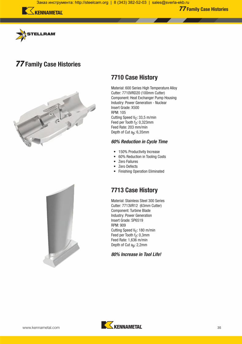
www.kennametal.com 35
7710 Case History
Material: 600 Series High Temperature AlloyCutter: 7710VRD20 (100mm Cutter)Component: Heat Exchanger Pump Housing Industry: Power Generation - NuclearInsert Grade: X500RPM: 105 Cutting Speed Vc: 33,5 m/minFeed per Tooth fz: 0,323mmFeed Rate: 203 mm/minDepth of Cut ap: 6,35mm
60% Reduction in Cycle Time
• 150% Productivity Increase • 60% Reduction in Tooling Costs • Zero Failures • Zero Defects • Finishing Operation Eliminated
7713 Case History
Material: Stainless Steel 300 SeriesCutter: 7713VR12 (63mm Cutter)Component: Turbine BladeIndustry: Power Generation Insert Grade: SP6519RPM: 909 Cutting Speed Vc: 180 m/minFeed per Tooth fz: 0,3mmFeed Rate: 1,636 m/minDepth of Cut ap: 2,2mm
80% Increase in Tool Life!
77 Family Case Histories
77 Family Case Histories
KMST-009_ExpFocusBroMetricUK_21-47.indd 35 4/25/14 4:28 PM
Заказ инструмента: http://steelcam.org | 8 (343) 382-52-03 | [email protected]

www.kennametal.com36
033100 7713VR10CA020Z2R40 10 1.89 22 38 3,33 64500033101 7713VR10CA025Z3R50 15 5.22 32 48 3,33 53500033102 7713VR10CA032Z3R70 22 8.64 46 62 3,33 53500033103 7713VR10CA032Z4R70 22 8.64 46 62 3,33 53500033104 7713VR10-A040Z05R 30 7.28 62 78 3,33 47000033105 7713VR10-A042Z06R 32 6.71 66 82 3,33 39500033106 7713VR10-A050Z06R 40 5.22 82 98 3,33 39500033107 7713VR10-A050Z07R 40 5.31 82 98 3,33 39500033108 7713VR10-A063Z08R 53 3.79 108 124 3,33 34000033109 7713VR10SA020Z2R25 10 1.89 22 38 3,33 64000033110 7713VR10SA025Z2R35 15 5.22 32 48 3,33 64000033111 7713VR10SA025Z3R35 15 5.22 32 48 3,33 64000033112 7713VR10SA032Z3R35 22 8.64 46 62 3,33 64000033113 7713VR10SA032Z4R35 22 8.64 46 62 3,33 53500033114 7713VR10SA035Z5R35 25 7.20 52 68 3,33 53500
033100 7713VR10CA020Z2R40 20 10 180 40 20 5 2 031233 D4007T 031654 TB15 3,10033101 7713VR10CA025Z3R50 25 15 200 50 25 5 3 031233 D4007T 031654 TB15 3,10033102 7713VR10CA032Z3R70 32 22 250 70 32 5 3 015260 D4008T 031654 TB15 3,10033103 7713VR10CA032Z4R70 32 22 250 70 32 5 4 015260 D4008T 031654 TB15 3,10 033104 7713VR10-A040Z05R 40 30 40 - 16 5 5 015260 D4008T 031654 TB15 3,10033105 7713VR10-A042Z06R 42 32 40 - 16 5 6 018481 D4006T 031654 TB15 3,10033106 7713VR10-A050Z06R 50 40 40 - 22 5 6 015260 D4008T 031654 TB15 3,10033107 7713VR10-A050Z07R 50 40 40 - 22 5 7 015260 D4008T 031654 TB15 3,10033108 7713VR10-A063Z08R 63 53 40 - 22 5 8 015260 D4008T 031654 TB15 3,10
d1
H
Da*
Da*
L
I1
M
L
Da*
d1
033109 7713VR10SA020Z2R25 20 10 25 M10 10.5 5 2 031233 D4007T 031654 TB15 3,10033110 7713VR10SA025Z2R35 25 15 35 M12 12.5 5 2 031233 D4007T 031654 TB15 3,10033111 7713VR10SA025Z3R35 25 15 35 M12 12.5 5 3 031233 D4007T 031654 TB15 3,10033112 7713VR10SA032Z3R35 32 22 35 M16 17.0 5 3 015260 D4008T 031654 TB15 3,10033113 7713VR10SA032Z4R35 32 22 35 M16 17.0 5 4 015260 D4008T 031654 TB15 3,10033114 7713VR10SA035Z5R35 35 25 35 M16 17.00 5 5 031233 D4007T 031654 TB15 3,10
ap
D
D
D*
d1
7713VR10 Technical Information (mm)
Product Dimensions
EDP Item Description Facing Pitch
Ramping Angle °
Helical Hole min. - max.
ap max Helical /Linear
Max RPM
D = Effective Diameter (Axis) from Insert centreline to centreline
D = Effective Diameter (Axis) from Insert centreline to centreline
Product Dimensions (mm) Spares
EDP Item Description Da*D
Effective Diameter
L M d1ap
maxNo. of Teeth EDP EDP
ScrewTightening
Nm
7713VR10 Modular Head - Medium and Fine Pitch
Product Dimensions (mm) Spares
EDP Item Description Da*D
Effective Diameter
L/H l1 d1ap
maxNo. of Teeth EDP EDP
ScrewTightening
Nm
7713VR10 Cylindrical Shank - Medium and Fine Pitch
7713VR10 Shell Mill Fixation - Medium and Fine Pitch
Modular Head
Cylindrical Shank
Shell Mill Fixation
Depth of Cut (ap)
Da* = Outside Diameter
Da* = Outside Diameter
Note: For cylindrical shank extensions in high density alloy with through coolant refer to page 45.The 7713VR10 series with anti-rotation pocket ensures a precise number of indexes per insert.
This unique patented pocket design prevents the inserts from rotating in the pocket during heavy feed machining and unstable conditions.
7713VR10Copy / Contour Milling Cutter
Flat
Facing Pitch
Ramping Helical Interpolation
KMST-009_ExpFocusBroMetricUK_21-47.indd 36 4/25/14 4:28 PM
Заказ инструмента: http://steelcam.org | 8 (343) 382-52-03 | [email protected]

www.kennametal.com 37
034546 RPEX10T3M0F-701-X4 SP4019 10,00 - 3,97 5,00 0,02
030456 RPEX10T3M0F-701-X4 GH1 10,00 - 3,97 5,00 0,02
034545 RPEX10T3M0E-701-X4 SP6519 - - 10,00 - 3,97 5,00 0,02
030449 RPHT10T3M0E-421-X4 X500 - - 10,00 - 3,97 5,00 0,04
030410 RPHT10T3M0E-421-X4 X700 - - 10,00 - 3,97 5,00 0,04
030452 RPMT10T3M0E-41-X4 X500 - - 10,00 - 3,97 5,00 0,04
031539 RPMT10T3M0E-41-X4 SP6519 - - 10,00 - 3,97 5,00 0,04
030451 RPMT10T3M0E-41-X4 MP91M - 10,00 - 3,97 5,00 0,04
030697 RPHT10T3M0E422-X4 X500 10,00 - 3,97 5,00 0,03
030767 RPHT10T3M0E-422-X4 X700 10,00 - 3,97 5,00 0,03
030862 RPHT10T3M0E-422-X4 SP6519 10,00 - 3,97 5,00 0,03
030329 RPHT10T3M0T-X4 X500 - 10,00 - 3,97 5,00 0,08
031555 RPHT10T3M0T-X4 SP6519 - 10,00 - 3,97 5,00 0,08
030454 RPMW10T3M0T-X4 X500 - 10,00 - 3,97 5,00 0,13
F-701-X4 SP4019 - - - - - - - 0,02 - 0,10 0,02 - 0,08 0,02 - 0,07 0,02 - 0,07 0,03 - 0,08 0,03 - 0,09 - -F-701-X4 GH1 - - - - - - - 0,02 - 0,10 0,02 - 0,08 - - - - - -
E-701-X4 SP6519 - - - - - - - - - 0,02 - 0,07 0,02 - 0,07 0,03 - 0,08 0,03 - 0,09 - -
E-421-X4 X500 - - - - - - - - - 0,04 - 0,08 0,04 - 0,08 0,04 - 0,09 0,04 - 0,11 - -E-421-X4 X700 - - - - - - - - - 0,04 - 0,08 0,04 - 0,08 0,04 - 0,09 0,04 - 0,11 - -
E-41-X4 X500 - - 0,04 - 0,18 - - - - - - - - - - - -E-41-X4 SP6519 0,04 - 0,18 0,04 - 0,16 0,04 - 0,18 - 0,04 - 0,18 0,04 - 0,18 0,04 - 0,16 - - - - - - - -E-41-X4 MP91M 0,04 - 0,18 0,04 - 0,16 - - 0,04 - 0,16 0,04 - 0,16 0,04 - 0,14 - - - - - - - -E-422-X4 X500 - - 0,06 - 0,30 0,06 - 0,25 - - - - - 0,06 - 0,14 0,06 - 0,14 0,06 - 0,16 0,06 - 0,18 - -E-422-X4 X700 - - 0,06 - 0,28 0,06 - 0,22 - - - - - 0,06 - 0,12 0,06 - 0,12 0,06 - 0,14 0,06 - 0,16 - -E-422-X4 SP6519 0,06 - 0,30 0,06 - 0,25 0,06 - 0,28 0,03 - 0,22 0,06 - 0,25 0,06 - 0,25 0,06 - 0,22 - - 0,06 - 0,12 0,06 - 0,12 0,06 - 0,14 0,06 - 0,16 - -
T-X4 X500 0,08 - 0,33 0,08 - 0,28 - - - - - - - - - - - - -T-X4 SP6519 0,08 - 0,32 0,08 - 0,27 - - 0,08 - 0,30 0,08 - 0,30 0,08 - 0,28 - - - - - - - -
T-X4 X500 0,13 - 0,35 0,13 - 0,33 0,13 - 0,35 0,13 - 0,30 - - - - - 0,13- 0,18 0,13 - 0,18 0,13 - 0,20 0,13 - 0,22 - -
RPEX10-701 RPHT10-421 RPMT10-41 RPHT10-422 RPHT10-T RPMW10-T
d s
Note: HTA = High Temperature Alloys
7713VR10 Feeds fz (mm/tooth)
Geom
etry
Grad
e
Oper
ation
Unall
oyed
St
eel
Alloy
ed
Stee
l
Stain
less
Stee
l
Stain
less S
teel
Refra
ctory
PH
Gray
Iro
n
Sphe
roida
l- Du
ctile
Iron
Malle
able
Iron
Alum
inium
&
Alloy
s <1
6% S
i 116
HBN
Alum
inium
&
Silic
on
>16
% S
i 92 H
BN
HTA
Iron
Base
d Allo
ys
HTA
Coba
lt Ba
sed A
lloys
HTA
Nick
elBa
sed A
lloys
HTA
Titan
ium
Base
d Allo
ys
Hard
Stee
l>1
400 N
/mm2
>415
HBN
Chille
d Cas
t Iron
>140
0 N/m
m2
>400
HBN
Min. - Max. Min. - Max. Min. - Max. Min. - Max. Min. - Max. Min. - Max. Min. - Max. Min. - Max. Min. - Max. Min. - Max. Min. - Max. Min. - Max. Min. - Max. Min. - Max. Min. - Max.ContouringContouring
Contouring
ContouringContouring
ContouringContouringContouring
ContouringContouringContouring
ContouringContouring
Contouring
Product Application & Material Dimensions (mm)
EDP Item Description Grade
Roughing Semi-Finishing Finishing
d (IC) l s r hm minDepth of Cut (mm)ap max ap min. - max. ap min. - max.5,00* 1,00 - 2,0 0,20 - 1,00
Machining Choice: 1st Choice 2nd Choice 3rd Choice | Material Guide Key descriptions found on page 46.
Speed recommendations can be found on page 41.
RPMW10T3MOT-X4 X500 is recommended for materials with heavy scale. *Max. recommended ap = 2,5mm (depending on the application)
7713VR10Milling Inserts & Recommended Feeds
KMST-009_ExpFocusBroMetricUK_21-47.indd 37 4/25/14 4:29 PM
Заказ инструмента: http://steelcam.org | 8 (343) 382-52-03 | [email protected]

www.kennametal.com38
033126 7713VR12CA025Z2R50 13 11.20 28 48 4,00 50000033127 7713VR12CA032Z3R70 20 10.80 42 62 4,00 40000033115 7713VR12-A040Z04R 28 7.90 58 78 4,00 34000033116 7713VR12-A040Z05R 28 7.90 58 78 4,00 34000033117 7713VR12-A050Z05R 38 5.50 78 98 4,00 29000033118 7713VR12-A050Z06R 38 5.50 78 98 4,00 29000033119 7713VR12-A052Z05R 40 5.15 82 102 4,00 28500033120 7713VR12-A052Z06R 40 5.15 82 102 4,00 28500033121 7713VR12-A063Z06R 51 3.85 104 124 4,00 25000033122 7713VR12-A063Z07R 51 3.85 104 124 4,00 25000033123 7713VR12-A066Z06R 54 3.60 110 130 4,00 24500033124 7713VR12-A066Z07R 54 3.60 110 130 4,00 24500033125 7713VR12-A080Z08R 68 2.75 138 158 4,00 21500033128 7713VR12SA025Z2R35 13 11.20 28 48 4,00 50000033129 7713VR12SA032Z3R35 20 10.80 42 62 4,00 40000033130 7713VR12SA040Z4R43 28 7.90 58 78 4,00 34000033131 7713VR12SA040Z5R43 28 7.90 58 78 4,00 34000
033128 7713VR12SA025Z2R35 25 13 35 M12 12,50 6 2 015260 D4008T 015240 T15 3,10033129 7713VR12SA032Z3R35 32 20 35 M16 17,00 6 3 015260 D4008T 015240 T15 3,10033130 7713VR12SA040Z4R43 40 28 43 M16 17,00 6 4 015260 D4008T 015240 T15 3,10033131 7713VR12SA040Z5R43 40 28 43 M16 17,00 6 5 015260 D4008T 015240 T15 3,10
ap
M
L
Da*
d1
D
d1
H
Da*
Da*
L
I1
D
D
033126 7713VR12CA025Z2R50 25 13 200 50 25 6 2 015260 D4008T 015240 T15 3,10033127 7713VR12CA032Z3R70 32 20 250 70 32 6 3 015260 D4008T 015240 T15 3,10 033115 7713VR12-A040Z04R 40 28 40 - 16 6 4 015262 D4010T 015240 T15 3,10033116 7713VR12-A040Z05R 40 28 40 - 16 6 5 015262 D4010T 015240 T15 3,10033117 7713VR12-A050Z05R 50 38 40 - 22 6 5 015262 D4010T 015240 T15 3,10033118 7713VR12-A050Z06R 50 38 40 - 22 6 6 015262 D4010T 015240 T15 3,10033119 7713VR12-A052Z05R 52 40 40 - 22 6 5 015262 D4010T 015240 T15 3,10033120 7713VR12-A052Z06R 52 40 40 - 22 6 6 015262 D4010T 015240 T15 3,10033121 7713VR12-A063Z06R 63 51 50 - 22 6 6 015262 D4010T 015240 T15 3,10033122 7713VR12-A063Z07R 63 51 50 - 22 6 7 015262 D4010T 015240 T15 3,10033123 7713VR12-A066Z06R 66 54 50 - 27 6 6 015262 D4010T 015240 T15 3,10033124 7713VR12-A066Z07R 66 54 50 - 27 6 7 015262 D4010T 015240 T15 3,10033125 7713VR12-A080Z08R 80 68 50 - 27 6 8 015262 D4010T 015240 T15 3,10
d1
D = Effective Diameter (Axis) from Insert centreline to centreline
D = Effective Diameter (Axis) from Insert centreline to centreline
7713VR12 Technical Information (mm)
Product Dimensions
EDP Item Description Facing Pitch
Ramping Angle °
Helical Hole min. - max.
ap max Helical /Linear
Max RPM
7713VR12 Cylindrcal Shank
7713VR12 Shell Mill Fixation - Medium and Fine Pitch
Product Dimensions (mm) Spares
EDP Item Description Da*D
Effective Diameter
L M d1ap
maxNo. of Teeth EDP EDP
ScrewTightening
Nm
7713VR12 Modular Head - Medium and Fine Pitch
Product Dimensions (mm) Spares
EDP Item Description Da*D
Effective Diameter
L/H l1 d1ap
maxNo. of Teeth EDP EDP
ScrewTightening
Nm
Cylindrical Shank
Shell Mill Fixation
Modular Head
Depth of Cut (ap)
Da* = Outside Diameter
Da* = Outside Diameter
Note: For cylindrical shank extensions in high density alloy with through coolant refer to page 45.
The 7713VR12 series with anti-rotation pocket ensures a precise number of indexes per insert.
This unique patented pocket design prevents the inserts from rotating in the pocket during heavy feed machining and unstable conditions.
7713VR12Contour Milling Cutter
Ramping Helical Interpolation
Flat
Facing Pitch
KMST-009_ExpFocusBroMetricUK_21-47.indd 38 4/25/14 4:29 PM
Заказ инструмента: http://steelcam.org | 8 (343) 382-52-03 | [email protected]

www.kennametal.com 39
029284 RPEX1204M0F-701-X4 GH1 12,00 4,76 6,00 0,02
029282 RPEX1204M0E-701-X4 X500 - - 12,00 - 4,76 6,00 0,03
029286 RPHT1204M0E-421-X4 X500 - 12,00 - 4,76 6,00 0,04
029700 RPHT1204M0E-421-X4 X700 - - 12,00 - 4,76 6,00 0,04
029272 RPMT1204M0E-41-X4 X500 - 12,00 - 4,76 6,00 0,05
031517 RPMT1204M0E-41-X4 SP6519 - 12,00 - 4,76 6,00 0,05
029291 RPMT1204M0E-41-X4 MP91M - 12,00 - 4,76 6,00 0,05
032129 RPHT1204M0E-442-X4 X500 - 12,00 - 4,76 6,00 0,04
032130 RPHT1204M0E-442-X4 X700 12,00 - 4,76 6,00 0,04
032128 RPHT1204M0E-442-X4 SP6519 12,00 - 4,76 6,00 0,04
029034 RPHT1204M0T-X4 X500 - - 12,00 - 4,76 6,00 0,10
029699 RPHT1204M0T-X4 X700 - - 12,00 - 4,76 6,00 0,10
031516 RPHT1204M0T-X4 SP6519 - - 12,00 - 4,76 6,0 0,10
029295 RPMW1204M0T-X4 X500 - - 12,00 - 4,76 6,00 0,13
031518 RPMW1204M0T-X4 SP6519 - - 12,00 - 4,76 6,00 0,13
029294 RPMW1204M0T-X4 MP91M - 12,00 - 4,76 6,00 0,13
RPEX12-701 RPHT12-421 RPHT12-442 RPHT12-T RPMW12-T
d s
RPMT12-41
Product Application & Material Dimensions (mm)
EDP Item Description Grade
Roughing Semi-Finishing Finishing
d (IC) l s r hm minDepth of Cut (mm)ap max ap min. - max. ap min. - max.6,00* 1,00 - 2,50 0,20 - 1,00
Machining Choice: 1st Choice 2nd Choice 3rd Choice | Material Guide Key descriptions found on page 46.
Note: Feed recommendations can be found on page 40. Speed recommendations can be found on page 41.
RPMW1204M0T-X4 should be used for materials with heavy scale * Max. recommended ap = 3,5mm (depending on the application)
7713VR12Milling Inserts
KMST-009_ExpFocusBroMetricUK_21-47.indd 39 4/25/14 4:29 PM
Заказ инструмента: http://steelcam.org | 8 (343) 382-52-03 | [email protected]

www.kennametal.com40
F-701-X4 GH1 - - - - - - - 0,03 - 0,12 0,03 - 0,10 - - - - - -
E-701-X4 X500 - - - - - - - - - 0,03 - 0,08 0,03 - 0,08 0,03 - 0,10 0,03 - 0,11 - -
E-421-X4 X500 - - - - - - - - - 0,04 - 0,20 0,04 - 0,20 0,04 - 0,22 0,04 - 0,24 - -E-421-X4 X700 - - 0,05 - 0,25 0,04 - 0,12 - - - - - 0,04 - 0,20 0,04 - 0,20 0,04 - 0,21 0,04 - 0,23 - -
E-41-X4 X500 - 0,05 - 0,22 0,05 - 0,25 - - - - - - - - - - - -E-41-X4 SP6519 0,05 - 0,25 0,05 - 0,22 - - 0,05 - 0,25 0,05 - 0,25 0,05 - 0,20 - - - - - - - -E-41-X4 MP91M 0,05 - 0,25 0,05 - 0,22 - - 0,05 - 0,25 0,05 - 0,25 0,05 - 0,20 - - - - - - - -
E-442-X4 X500 - - 0,06 - 0,40 0,06 - 0,33 - - - - - 0,06 - 0,24 0,06 - 0,24 0,06 - 0,24 0,06 - 0,26 - -E-442-X4 X700 - - 0,06 - 0,38 0,06 - 0,31 - - - - - 0,06 - 0,23 0,06 - 0,23 0,06 - 0,23 0,06 - 0,25 - -E-442-X4 SP6519 0,06 - 0,45 0,06 - 0,38 0,06 - 0,38 0,06 - 0,31 0,06 - 0,40 0,06 - 0,40 0,06 - 0,35 - - 0,06 - 0,23 0,06 - 0,23 0,06 - 0,23 0,06 - 0,25 - -
RPHT-T-X4 X500 - 0,15 - 0,40 - - - - - - - - - - - - -
RPHT-T-X4 X700 - - - 0,15 - 0,35 - - - - - - - - - - -
RPHT-T-X4 SP6519 0,15 - 0,45 0,15 - 0,40 - - 0,15 - 0,45 0,15 - 0,45 0,15 - 0,40 - - - - - - - -
RPMW-T-X4 X500 - - 0,13 - 0,35 0,13 - 0,30 - - - - - 0,13 - 0,25 0,13 - 0,25 0,13 - 0,27 0,13 - 0,29 - -
RPMW-T-X4 SP6519 0,13 - 0,45 0,13 - 0,40 - - 0,13 - 0,45 0,13 - 0,45 0,13 - 0,40 - - - - - - - -
RPMW-T-X4 MP91M 0,13 -0,42 - - - 0,13 - 0,42 0,13 - 0,42 0,13 - 0,35 - - - - - - 0,09 - 0,15 0,09 - 0,15
Note: HTA = High Temperature Alloys
7713VR12 Feeds fz (mm/tooth)
Geom
etry
Grad
e
Oper
ation
Unall
oyed
St
eel
Alloy
ed
Stee
l
Stain
less
Stee
l
Stain
less S
teel
Refra
ctory
PH
Gray
Iro
n
Sphe
roida
l- Du
ctile
Iron
Malle
able
Iron
Alum
inium
&
Alloy
s <1
6% S
i 116
HBN
Alum
inium
&
Silic
on
>16
% S
i 92 H
BN
HTA
Iron
Base
d Allo
ys
HTA
Coba
lt Ba
sed A
lloys
HTA
Nick
elBa
sed A
lloys
HTA
Titan
ium
Base
d Allo
ys
Hard
Stee
l>1
400 N
/mm2
>415
HBN
Chille
d Cas
t Iron
>140
0 N/m
m2
>400
HBN
Min. - Max. Min. - Max. Min. - Max. Min. - Max. Min. - Max. Min. - Max. Min. - Max. Min. - Max. Min. - Max. Min. - Max. Min. - Max. Min. - Max. Min. - Max. Min. - Max. Min. - Max.Contouring
Contouring
ContouringContouring
ContouringContouringContouring
ContouringContouringContouring
Contouring
Contouring
Contouring
Contouring
Contouring
Contouring
Speed recommendations can be found on page 41.
7713VR12Recommended Feeds
KMST-009_ExpFocusBroMetricUK_21-47.indd 40 4/25/14 4:29 PM
Заказ инструмента: http://steelcam.org | 8 (343) 382-52-03 | [email protected]

www.kennametal.com 41
P
130 - 270
130 - 295
140 - 345
115 - 240 115 - 260 120 - 305
100 - 210
100 - 230
105 - 270
75 - 160 75 - 175 80 - 205
50 - 100 50 - 110 50 - 130
-- +
M
115 - 250
115 - 260
115 - 270
100 - 220 105 - 230 105 - 235
50 - 110 50 - 115 50 - 120
K
140 - 295
145 - 365
110 - 240 115 - 285
100 - 220 105 - 260
N
400 - 2895
400 - 3050
295 - 2320 295 - 2440
S
23 - 48
23 - 52
23 - 55
24 - 63
21 - 44 22 - 46 22 - 48 23 - 52
24 - 51 25 - 53 25 - 55 26 - 59
35 - 73 36 - 75 36 - 79 37 - 84
H
50 - 105
40 - 95
Recommended Possible
Speed vc (m/min)
7713VR SeriesWear Resistance
Speed min. - max.
Coolant Recommendation CVDX Grade
PVDX Grade
PVDStandard
PVDStandard
CVDStandard
Uncoated Micrograin
ISO Materials Rm and Hardness X500 X700 SP6519 SP4019 MP91M GH1
UnalloyedSteel
<600 N/mm2
<180 HBN<950 N/mm2
<280 HBN
AlloyedSteel
700-950 N/mm2
200-280 HBN950-1200 N/mm2
280-355 HBN1200-1400 N/mm2
355-415 HBN
StainlessSteel
Austenitic + Ferritic300 seriesMartensitic400 series
PH Stainless RefractoryP.H.
Cast Iron
GreyGG-Ft
Spheroidal-DuctileGGG-FGSMalleable
GTS - MN/MP
Aluminium & Alloys
Aluminium & Alloys < 16% Si 116 HBN
Aluminium + Silicon > 16% Si 92 HBN
HighTemperature
Alloys
Iron Based
Cobalt Based
Nickel Based
Titanium Based
Hard Materials
Hard Steel>1400 N/mm2
>415 HBNChilled Cast Iron
>1400 N/mm2 > 400 HBN
7713VRRecommended Speeds
KMST-009_ExpFocusBroMetricUK_21-47.indd 41 4/25/14 4:29 PM
Заказ инструмента: http://steelcam.org | 8 (343) 382-52-03 | [email protected]

www.kennametal.com42
ap
Dw
D2
r
7713VR Technical Information
7713VR Technical Information
fz = hm x
Simplified formulas to evaluate hm and fz based on axial depth of cut or radial engagement.
Calculation of the average chip thickness in relation with the D.O.C. (Axial)
hm = fz x
Formula: Average Chip Thickness (hm)hm = Average chip thicknessap = Depth of cutfz = Feed per toothd = Insert diameter
fz = hm x
Formula: Programme Feed Rate (fz)
Calculation of the average chip thickness in relation with the ae (Radial Engagement) if ae is less than 50% of Dia.
hm = fz x
Formula: Average Chip Thickness (hm)hm = Average chip thicknessae = Radial engagementfz = Feed per toothd = Cutter diameter
Formula: Programme Feed Rate (fz)
x( )2r2 - r - ap
r
Formula to calculate the average chip thickness hm in relation with radial engagement and depth of cut.
Formula to find programmed feed rate based on radial engagement and axial depth of cut.
x( )2r2 - r - ap
r
hm fz =
hm = fz x
where: fz = Feed per tooth hm = Average chip thickness r = Insert radius
ae = Radial Depth of Cut ap = Axial Depth of Cut
ap
ddap
ae
ddae
r2 - r - ae r
( )2
r2 - r - ae r
( )2
Formula to evaluate the correct working diameter based on axial depth of cut (ap).
where: Dw = Working Diameter D2 = Diameter of cutter insert centre to centre r = Insert radius ap = Axial Depth of Cut
Working Diameter:
Dw = D2 + 2 x r2 - (r -ap)2
7713VRTechnical Information
KMST-009_ExpFocusBroMetricUK_21-47.indd 42 4/25/14 4:29 PM
Заказ инструмента: http://steelcam.org | 8 (343) 382-52-03 | [email protected]

www.kennametal.com 43
F-701-X4
10,00 0,25 0,02 0,08 0,13 0,5110,00 0,50 0,02 0,08 0,09 0,3610,00 0,75 0,02 0,08 0,07 0,2910,00 1,00 0,02 0,08 0,06 0,2510,00 1,25 0,02 0,08 0,06 0,2310,00 1,50 0,02 0,08 0,05 0,2110,00 2,00 0,02 0,08 0,04 0,1810,00 2,50 0,02 0,08 0,04 0,16
E-701-X4
10,00 0,25 0,03 0,09 0,19 0,5710,00 0,50 0,03 0,09 0,13 0,4010,00 0,75 0,03 0,09 0,11 0,3310,00 1,00 0,03 0,09 0,09 0,2810,00 1,25 0,03 0,09 0,08 0,2510,00 1,50 0,03 0,09 0,08 0,2310,00 2,00 0,03 0,09 0,07 0,2010,00 2,50 0,03 0,09 0,06 0,18
E-421-X4
10,00 0,25 0,04 0,10 0,25 0,6310,00 0,50 0,04 0,10 0,18 0,4510,00 0,75 0,04 0,10 0,15 0,3710,00 1,00 0,04 0,10 0,13 0,3210,00 1,25 0,04 0,10 0,11 0,2810,00 1,50 0,04 0,10 0,10 0,2610,00 2,00 0,04 0,10 0,09 0,2210,00 2,50 0,04 0,10 0,08 0,20
E-41-X4
10,00 0,25 0,04 0,12 0,25 0,7610,00 0,50 0,04 0,12 0,18 0,5410,00 0,75 0,04 0,12 0,15 0,4410,00 1,00 0,04 0,12 0,13 0,3810,00 1,25 0,04 0,12 0,11 0,3410,00 1,50 0,04 0,12 0,10 0,3110,00 2,00 0,04 0,12 0,09 0,2710,00 2,50 0,04 0,12 0,08 0,24
E-422-X4
10,00 0,25 0,04 0,16 0,25 1,0110,00 0,50 0,04 0,16 0,18 0,7210,00 0,75 0,04 0,16 0,15 0,5810,00 1,00 0,04 0,16 0,13 0,5110,00 1,25 0,04 0,16 0,11 0,4510,00 1,50 0,04 0,16 0,10 0,4110,00 2,00 0,04 0,16 0,09 0,3610,00 2,50 0,04 0,16 0,08 0,32
RPHT-T-X4
10,00 0,25 0,08 0,18 0,51 1,1410,00 0,50 0,08 0,18 0,36 0,8010,00 0,75 0,08 0,18 0,29 0,6610,00 1,00 0,08 0,18 0,25 0,5710,00 1,25 0,08 0,18 0,23 0,5110,00 1,50 0,08 0,18 0,21 0,4610,00 2,00 0,08 0,18 0,18 0,4010,00 2,50 0,08 0,18 0,16 0,36
RPMW-T-X4
10,00 0,25 0,13 0,19 0,82 1,2010,00 0,50 0,13 0,19 0,58 0,8510,00 0,75 0,13 0,19 0,47 0,6910,00 1,00 0,13 0,19 0,41 0,6010,00 1,25 0,13 0,19 0,37 0,5410,00 1,50 0,13 0,19 0,34 0,4910,00 2,00 0,13 0,19 0,29 0,4210,00 2,50 0,13 0,19 0,26 0,38
Inserts RP..10T3..Dimensions (mm)
InsertsGeometry
InsertSize
apAxial d.o.c.
hmmin.
hmmax.
fzmin.
fzmax.
With round inserts, the thickness of the chip varies depending on the axial depth of cut and is related to the size of the cutting edge preparation. For best tool-life it is important to maintain the proper chip thickness as shown below.
7713VR10Technical Information
KMST-009_ExpFocusBroMetricUK_21-47.indd 43 4/25/14 4:29 PM
Заказ инструмента: http://steelcam.org | 8 (343) 382-52-03 | [email protected]
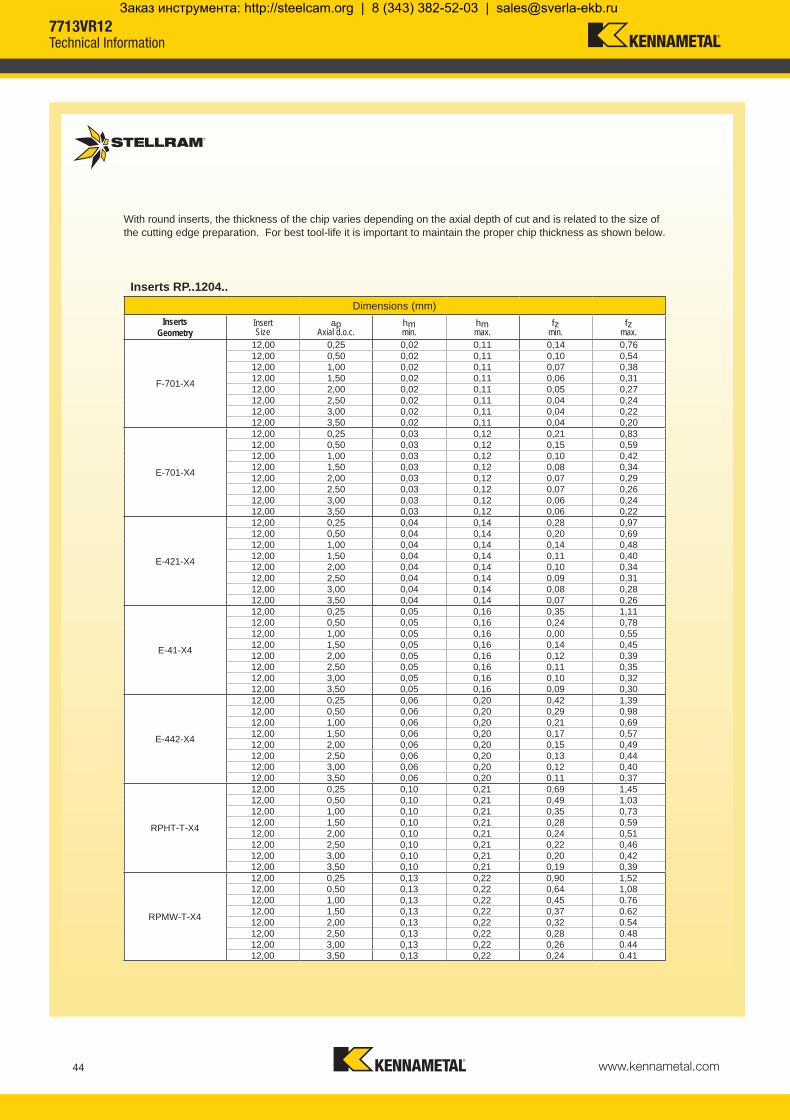
www.kennametal.com44
F-701-X4
12,00 0,25 0,02 0,11 0,14 0,7612,00 0,50 0,02 0,11 0,10 0,5412,00 1,00 0,02 0,11 0,07 0,3812,00 1,50 0,02 0,11 0,06 0,3112,00 2,00 0,02 0,11 0,05 0,2712,00 2,50 0,02 0,11 0,04 0,2412,00 3,00 0,02 0,11 0,04 0,2212,00 3,50 0,02 0,11 0,04 0,20
E-701-X4
12,00 0,25 0,03 0,12 0,21 0,8312,00 0,50 0,03 0,12 0,15 0,5912,00 1,00 0,03 0,12 0,10 0,4212,00 1,50 0,03 0,12 0,08 0,3412,00 2,00 0,03 0,12 0,07 0,2912,00 2,50 0,03 0,12 0,07 0,2612,00 3,00 0,03 0,12 0,06 0,2412,00 3,50 0,03 0,12 0,06 0,22
E-421-X4
12,00 0,25 0,04 0,14 0,28 0,9712,00 0,50 0,04 0,14 0,20 0,6912,00 1,00 0,04 0,14 0,14 0,4812,00 1,50 0,04 0,14 0,11 0,4012,00 2,00 0,04 0,14 0,10 0,3412,00 2,50 0,04 0,14 0,09 0,3112,00 3,00 0,04 0,14 0,08 0,2812,00 3,50 0,04 0,14 0,07 0,26
E-41-X4
12,00 0,25 0,05 0,16 0,35 1,1112,00 0,50 0,05 0,16 0,24 0,7812,00 1,00 0,05 0,16 0,00 0,5512,00 1,50 0,05 0,16 0,14 0,4512,00 2,00 0,05 0,16 0,12 0,3912,00 2,50 0,05 0,16 0,11 0,3512,00 3,00 0,05 0,16 0,10 0,3212,00 3,50 0,05 0,16 0,09 0,30
E-442-X4
12,00 0,25 0,06 0,20 0,42 1,3912,00 0,50 0,06 0,20 0,29 0,9812,00 1,00 0,06 0,20 0,21 0,6912,00 1,50 0,06 0,20 0,17 0,5712,00 2,00 0,06 0,20 0,15 0,4912,00 2,50 0,06 0,20 0,13 0,4412,00 3,00 0,06 0,20 0,12 0,4012,00 3,50 0,06 0,20 0,11 0,37
RPHT-T-X4
12,00 0,25 0,10 0,21 0,69 1,4512,00 0,50 0,10 0,21 0,49 1,0312,00 1,00 0,10 0,21 0,35 0,7312,00 1,50 0,10 0,21 0,28 0,5912,00 2,00 0,10 0,21 0,24 0,5112,00 2,50 0,10 0,21 0,22 0,4612,00 3,00 0,10 0,21 0,20 0,4212,00 3,50 0,10 0,21 0,19 0,39
RPMW-T-X4
12,00 0,25 0,13 0,22 0,90 1,5212,00 0,50 0,13 0,22 0,64 1,0812,00 1,00 0,13 0,22 0,45 0.7612,00 1,50 0,13 0,22 0,37 0.6212,00 2,00 0,13 0,22 0,32 0.5412,00 2,50 0,13 0,22 0,28 0.4812,00 3,00 0,13 0,22 0,26 0.4412,00 3,50 0,13 0,22 0,24 0.41
Inserts RP..1204..Dimensions (mm)
InsertsGeometry
InsertSize
apAxial d.o.c.
hmmin.
hmmax.
fzmin.
fzmax.
With round inserts, the thickness of the chip varies depending on the axial depth of cut and is related to the size of the cutting edge preparation. For best tool-life it is important to maintain the proper chip thickness as shown below.
7713VR12Technical Information
KMST-009_ExpFocusBroMetricUK_21-47.indd 44 4/25/14 4:29 PM
Заказ инструмента: http://steelcam.org | 8 (343) 382-52-03 | [email protected]

www.kennametal.com 45
D
L
D2
D1
L1
030624 M-13-M8-CA16-090 90 40 16 13 8,50 M8030625 M-13-M8-CA16-110 110 60 16 13 8,50 M8030626 M-13-M8-CA16-130 130 80 16 13 8,50 M8030627 M-13-M8-CA16-170 170 120 16 13 8,50 M8030628 M-18-M10-CA20-110 110 60 20 18 10,50 M10030629 M-18-M10-CA20-130 130 80 20 18 10,50 M10030630 M-18-M10-CA20-170 170 120 20 18 10,50 M10030631 M-18-M10-CA20-190 190 140 20 18 10,50 M10030632 M-21-M12-CA25-131 131 75 25 21 12,50 M12030633 M-21-M12-CA25-156 156 100 25 21 12,50 M12030634 M-21-M12-CA25-181 181 125 25 21 12,50 M12030635 M-21-M12-CA25-206 206 150 25 21 12,50 M12030636 M-21-M12-CA25-231 231 175 25 21 12,50 M12030637 M-29-M16-CA32-160 160 100 32 29 17,00 M16030638 M-29-M16-CA32-210 210 150 32 29 17,00 M16030639 M-29-M16-CA32-260 260 200 32 29 17,00 M16030640 M-29-M16-CA32-310 310 250 32 29 17,00 M16
Product Dimensions (mm)
EDP Item Description L L1 D2 D D1 M
Technical Advice
M Modular adapter 13 Diameter in front of the modular shank (D) M8 Metric Thread (M) CA16 Cylindrical shank diameter 16mm with through coolant 90 Total length of the body
Shank Extension
Cylindrical shank extensions can be used with all modular heads found in several product family series within this catalogue.
These extensions have the industry standard of metric threads.
Note: Order example with cylindrical shank: M-13-M8-CA16-090
Cylindrical Shank Extensions for Modular HeadsAnti-Vibration Tungsten Alloy with Through Coolant
KMST-009_ExpFocusBroMetricUK_21-47.indd 45 4/25/14 4:29 PM
Заказ инструмента: http://steelcam.org | 8 (343) 382-52-03 | [email protected]
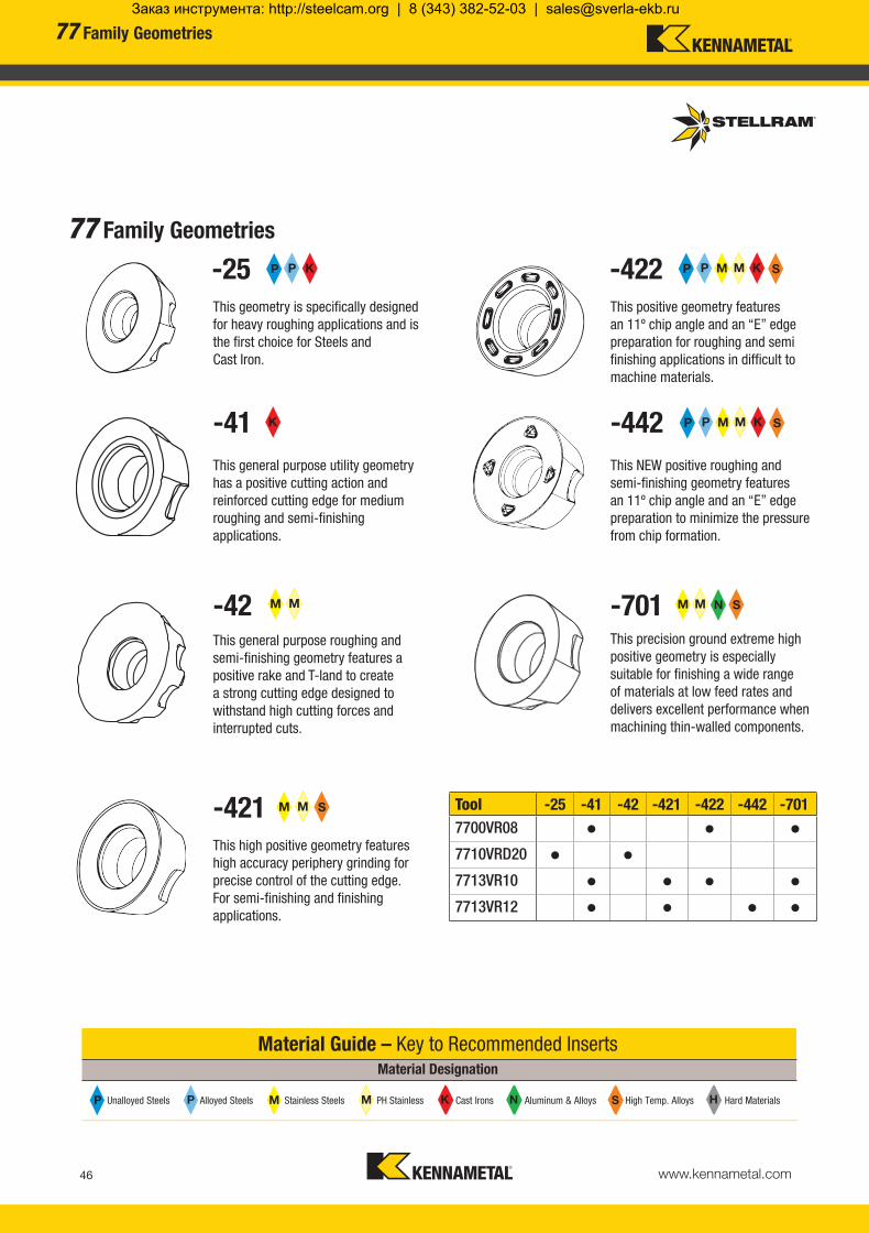
www.kennametal.com46
P P M M K N S HK N S H
Tool -25 -41 -42 -421 -422 -442 -7017700VR08 • • •7710VRD20 • •7713VR10 • • • •7713VR12 • • • •
P P K
M M S
M M
K
P P M M K S
P P M M K S
M M N S
Material Guide – Key to Recommended InsertsMaterial Designation
Alloyed Steels PH Stainless Aluminum & Alloys High Temp. Alloys Hard MaterialsUnalloyed Steels Stainless Steels Cast Irons
77 Family Geometries
-25 -422
-41 -442
-42 -701
-421
This geometry is specifically designed for heavy roughing applications and is the first choice for Steels and Cast Iron.
This positive geometry features an 11º chip angle and an “E” edge preparation for roughing and semi finishing applications in difficult to machine materials.
This general purpose utility geometry has a positive cutting action and reinforced cutting edge for medium roughing and semi-finishing applications.
This NEW positive roughing and semi-finishing geometry features an 11º chip angle and an “E” edge preparation to minimize the pressure from chip formation.
This general purpose roughing and semi-finishing geometry features a positive rake and T-land to create a strong cutting edge designed to withstand high cutting forces and interrupted cuts.
This precision ground extreme high positive geometry is especially suitable for finishing a wide range of materials at low feed rates and delivers excellent performance when machining thin-walled components.
This high positive geometry features high accuracy periphery grinding for precise control of the cutting edge. For semi-finishing and finishing applications.
77 Family Geometries
KMST-009_ExpFocusBroMetricUK_21-47.indd 46 4/25/14 4:29 PM
Заказ инструмента: http://steelcam.org | 8 (343) 382-52-03 | [email protected]

www.kennametal.com 47
P P M M K N S H
Tool GH1 MP91M SP4019 SP6519 X500 X700
7700VR08 • • • • •7710VRD20 • •7713VR10 • • • • • •7713VR12 • • • • •
N
K
S M M S
P P M M K S
P P M M S
Material Guide – Key to Recommended InsertsMaterial Designation
Alloyed Steels PH Stainless Aluminum & Alloys High Temp. Alloys Hard MaterialsUnalloyed Steels Stainless Steels Cast Irons
77 Family Grades
GH1
SP4019
SP6519
X500
X700
MP91M
Uncoated, Micrograin
This micrograin grade works well with or without coolant with low cutting pressure at high speeds due to sharp cutting edge.
Coating Type: PVD, TiAlN Micrograin
This hard grade is designed for light roughing and finishing operations with lower chip sections.
Coating Type: PVD, TiAlN, X-Grade™ Technology
This combination of a highly durable TiAIN PVD coating and specially developed carbide substrate delivers excellent tool life during long contact times of the cutting edge.
Coating Type: PVD, TiAlN
This grade features a combination of a tough substrate with a new generation of TiAlN super nano coating, making it virtually free of residual stress and extremely hard for unmatched performance.
Coating Type: CVD, TiN-TiC-TiN, X-Grade™ Technology
High level of shock resistance; operates at low to medium cutting speeds; high metal removal rates while retaining a secure cutting edge.
Coating Type: CVD, TiN-MT-TiCN-Al2O3
With its aluminium oxide coating, this grade is recommended every time wear characteristics are more important than toughness.
77 Family Grades
KMST-009_ExpFocusBroMetricUK_21-47.indd 47 4/25/14 4:29 PM
Заказ инструмента: http://steelcam.org | 8 (343) 382-52-03 | [email protected]

www.kennametal.com48
KMST-009_ExpFocusBroMetricUK_48-IBC.indd 48 4/25/14 4:36 PM
Заказ инструмента: http://steelcam.org | 8 (343) 382-52-03 | [email protected]

www.kennametal.com 49
5230 Chevron Long Edge Milling
Setting New Standards of Productivity• Unique insert alignment reduces cutting forces
• Each insert has its own coolant jet for maximum chip evacuation
• Continuous engagement for maximum material removal
KMST-009_ExpFocusBroMetricUK_48-IBC.indd 49 4/25/14 4:36 PM
Заказ инструмента: http://steelcam.org | 8 (343) 382-52-03 | [email protected]

www.kennametal.com50
The 5230VS Series: Cut Machining Time by up to 50% or More
• 90 degree roughing
• High Metal Removal Rates
• High Stability and Rigidity
• Square inserts, 4 cutting edges
• Three grades, four geometries
• Shell and Cylindrical construction
• Standard and long series available
• Cutting diameters from 50mm to 100mm
• Insert sizes 9,52mm and 12,70mm
• Depth of cut from 51mm to 133mm
5230 Case Histories
Material: Titanium 555-3Cutter: 5230VS12 (63mm Cutter)Component: Landing GearIndustry: AerospaceInsert Grade: X500RPM: 150 Cutting Speed Vc: 29,7 m/minFeed per Tooth fz: 0,1 mm/minFeed Rate: 60 mm/minDepth of Cut ap: 50mm
Increased Metal Removal Rate by 300%!
Material: Titanium 6-4Cutter: 5230VS12 (80mm Cutter)Component: BulkheadIndustry: AerospaceInsert Grade: X500RPM: 275Cutting Speed Vc: 69,0 m/minFeed per Tooth fz: 0,1 mm/minFeed Rate: 148 mm/minDepth of Cut ap: 60mm
Incredible Metal Removal Rate of 43 in3 / min.
Shell50mm – 100mm
5230 Chevron Long Edge Milling
KMST-009_ExpFocusBroMetricUK_48-IBC.indd 50 4/25/14 4:36 PM
Заказ инструмента: http://steelcam.org | 8 (343) 382-52-03 | [email protected]

www.kennametal.com 51
Engineered from the Inside Out Axial Engagement is the Key
5230 Case Histories
Material: Titanium 555-3Cutter: 5230VS12 (63mm Cutter)Component: Landing GearIndustry: AerospaceInsert Grade: X500RPM: 150 Cutting Speed Vc: 29,7 m/minFeed per Tooth fz: 0,1 mm/minFeed Rate: 60 mm/minDepth of Cut ap: 50mm
Increased Metal Removal Rate by 300%!
Material: Titanium 6-4Cutter: 5230VS12 (80mm Cutter)Component: BulkheadIndustry: AerospaceInsert Grade: X500RPM: 275Cutting Speed Vc: 69,0 m/minFeed per Tooth fz: 0,1 mm/minFeed Rate: 148 mm/minDepth of Cut ap: 60mm
Incredible Metal Removal Rate of 43 in3 / min.
Single line contact… no two inserts are contacting the work piece on the same axial plane—to reduce vibration and
maximize feed rates
Insert positioning provides smooth progressive penetration and cutting action for extended tool life.
Short bolt design opens center for a coolant reservoir
Full, effective flute for maximum chip flow
Coolant reservoir for more even distribution
Each insert has its own coolant jet for optimum chip evacuation
Threaded coolant ports allow selective blocking to adjust pressure and volume
Wiper pockets provide a much better face surface finish
Coolant plug
Non-wiper pockets generate the 90° corner. The same inserts can be utilized in all pockets
The advanced Chevron Design ensures that one cutting point is always in contact with the material during entrance and exit. This provides optimum harmonic stability, reducing power consumption and maximizing tool life.
5230 Chevron Long Edge Milling
KMST-009_ExpFocusBroMetricUK_48-IBC.indd 51 4/25/14 4:36 PM
Заказ инструмента: http://steelcam.org | 8 (343) 382-52-03 | [email protected]

www.kennametal.com52
031419 5230VS09-A050Z4R51 50 76 - 27 51 44 4 28 015269 F3508T 015240 T15 2,10031603 5230VS09-A050Z4R80 50 106 - 27 80 - 4 44 015269 F3508T 015240 T15 2,10
031419 5230VS09-A050Z4R51 50 - - - - 32500031603 5230VS09-A050Z4R80 50 - - - - 32500
5230VS09-A050Z4R51 015062 F3006T 8 013214 T9 031436 SB-3413 345230VS09-A050Z4R80 12 031582 SB-3621
5230VS09-A050Z4R51 031258 NLW-0.375 031268 M12-1.75 ISO x 30mm SHCS 80 1005230VS09-A050Z4R80
d1
H
D
apmax
Flat
Facing Pitch
5230VS09 Technical Information (mm)
Product Dimensions
EDP Item Description Facing Pitch
Ramping Angle °
Helical Hole min. - max.
ap max Helical /Linear
Max RPM
5230VS09 Torque Values and Spare Parts
CutterNord Lock Washer Mounting Bolt **Torque Values in Nm
EDP Description EDP Description Normal Condition Excessive Condition
5230VS09 Spare Parts
CutterCoolant Control Screw Screwdriver
EDPSteel Coolant Plug Coolant Plug
tighteningNmScrew EDP Screw Qty. EDP Description
* Note: Please do not surpass the recommended max. ap for slotting.
Product Dimensions (mm) Spares
EDP Item Description D L/H l1 d1 ap max
ap max
Slotting*No. of flutes
No. of inserts EDP EDP
ScrewTightening
Nm
5230VS09 Shell Mill Fixation
** Torque values for mounting bolts. Excessive condition is when long reach extensions are required or when cutting parameters are elevated to extreme parameters.
Shell Mills are supplied with inserts screws, coolant control screws, steel coolant plug, nord-lock washer and mounting screw.
Shell Mill Fixation
5230VS09Chevron Long Edge Milling Cutter (Porcupine)
KMST-009_ExpFocusBroMetricUK_48-IBC.indd 52 4/25/14 4:36 PM
Заказ инструмента: http://steelcam.org | 8 (343) 382-52-03 | [email protected]

www.kennametal.com 53
031261 SDHT09T308EN-422 X500 - 9,52 9,52 3,97 0,80 0,03
033075 SDHT09T308EN-422 SP6519 - 9,52 9,52 3,97 0,80 0,03
031260 SDHT09T308EN-423 X500 - - 9,52 9,52 3,97 0,80 0,04
033074 SDHT09T308EN-423 SP6519 - 9,52 9,52 3,97 0,80 0,04
014410 SDMT09T308EN-41 X500 - 9,52 9,52 3,97 0,80 0,04
031479 SDMT09T308EN-41 SP6519 - 9,52 9,52 3,97 0,80 0,04
017325 SDMT09T308EN-41 MP91M - 9,52 9,52 3,97 0,80 0,04
015232 SDMW09T308TN X500 - - 9,52 9,52 3,97 0,80 0,15
031482 SDMW09T308TN SP6519 - - 9,52 9,52 3,97 0,80 0,15
017327 SDMW09T308TN MP91M - - 9,52 9,52 3,97 0,80 0,15
SDHT09-422 SDHT09-423 SDMT09-41 SDMW09-TN
d
l
r
s
Product Application & Material Dimensions (mm)
EDP Item Description Grade
Roughing Semi-Finishing Finishing
d (IC) l s r hm minDepth of Cut (mm)ap max* or ap max. and ap min. - max.ae max.* ae max. 15% D**
Machining Choice: 1st Choice 2nd Choice 3rd Choice | Material Guide Key descriptions found on page 63.
Note: Feed recommendations can be found on page 54. Speed recommendations can be found on page 55.
* Note: Please do not surpass the recommended max. ap for slotting as shown on the steel body page 52. * Note: ap max. for profiling is only possible when ae < 75% of the Diameter. ** Note: For semi finishing, axial engagement ap for slotting and radial engagement ae for profiling should be max. 15% of the Diameter. SDHT09T308EN-423 to be used in unstable conditions.
5230VS09Milling Inserts
KMST-009_ExpFocusBroMetricUK_48-IBC.indd 53 4/25/14 4:36 PM
Заказ инструмента: http://steelcam.org | 8 (343) 382-52-03 | [email protected]
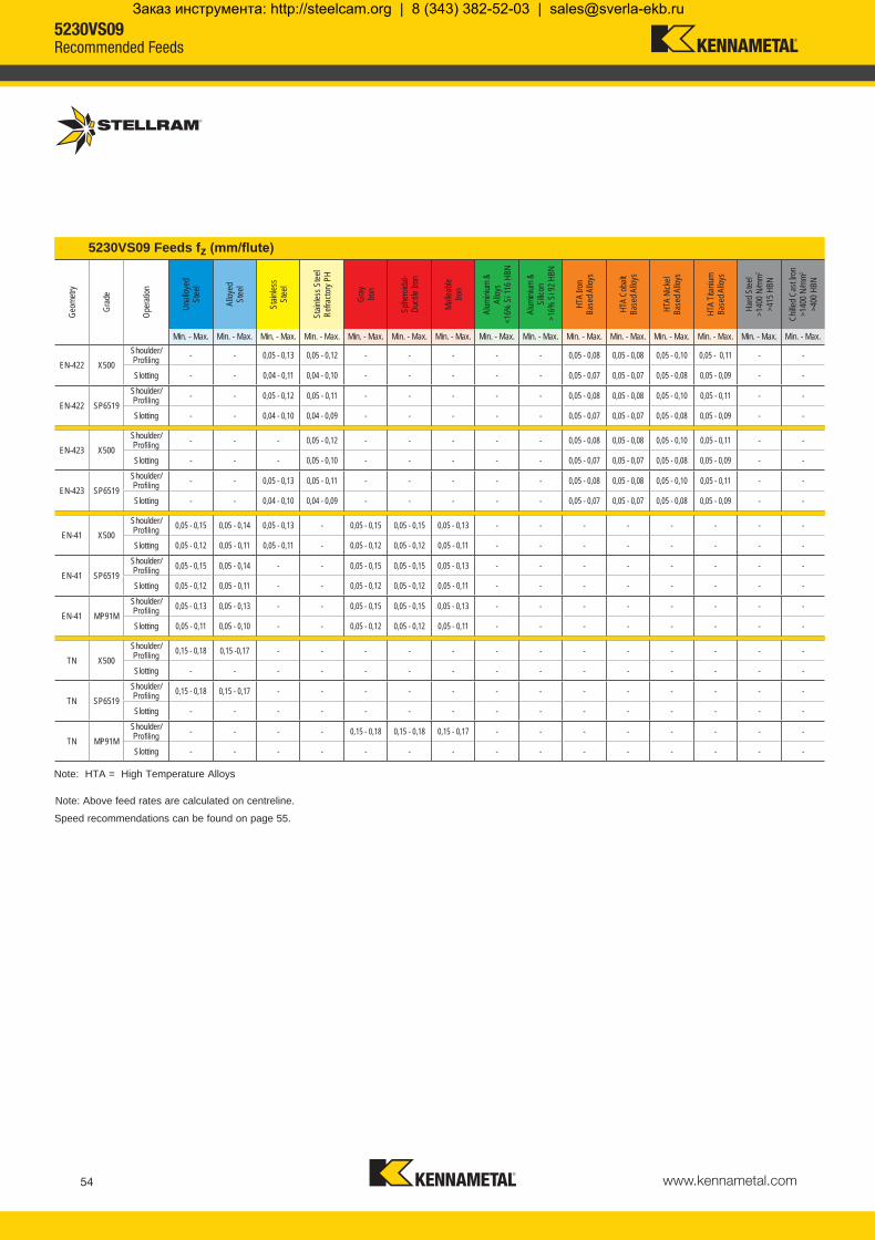
www.kennametal.com54
EN-422 X500- - 0,05 - 0,13 0,05 - 0,12 - - - - - 0,05 - 0,08 0,05 - 0,08 0,05 - 0,10 0,05 - 0,11 - -
- - 0,04 - 0,11 0,04 - 0,10 - - - - - 0,05 - 0,07 0,05 - 0,07 0,05 - 0,08 0,05 - 0,09 - -
EN-422 SP6519- - 0,05 - 0,12 0,05 - 0,11 - - - - - 0,05 - 0,08 0,05 - 0,08 0,05 - 0,10 0,05 - 0,11 - -
- - 0,04 - 0,10 0,04 - 0,09 - - - - - 0,05 - 0,07 0,05 - 0,07 0,05 - 0,08 0,05 - 0,09 - -
EN-423 X500- - - 0,05 - 0,12 - - - - - 0,05 - 0,08 0,05 - 0,08 0,05 - 0,10 0,05 - 0,11 - -
- - - 0,05 - 0,10 - - - - - 0,05 - 0,07 0,05 - 0,07 0,05 - 0,08 0,05 - 0,09 - -
EN-423 SP6519- - 0,05 - 0,13 0,05 - 0,11 - - - - - 0,05 - 0,08 0,05 - 0,08 0,05 - 0,10 0,05 - 0,11 - -
- - 0,04 - 0,10 0,04 - 0,09 - - - - - 0,05 - 0,07 0,05 - 0,07 0,05 - 0,08 0,05 - 0,09 - -
EN-41 X5000,05 - 0,15 0,05 - 0,14 0,05 - 0,13 - 0,05 - 0,15 0,05 - 0,15 0,05 - 0,13 - - - - - - - -
0,05 - 0,12 0,05 - 0,11 0,05 - 0,11 - 0,05 - 0,12 0,05 - 0,12 0,05 - 0,11 - - - - - - - -
EN-41 SP65190,05 - 0,15 0,05 - 0,14 - - 0,05 - 0,15 0,05 - 0,15 0,05 - 0,13 - - - - - - - -
0,05 - 0,12 0,05 - 0,11 - - 0,05 - 0,12 0,05 - 0,12 0,05 - 0,11 - - - - - - - -
EN-41 MP91M0,05 - 0,13 0,05 - 0,13 - - 0,05 - 0,15 0,05 - 0,15 0,05 - 0,13 - - - - - - - -
0,05 - 0,11 0,05 - 0,10 - - 0,05 - 0,12 0,05 - 0,12 0,05 - 0,11 - - - - - - - -
TN X5000,15 - 0,18 0,15 -0,17 - - - - - - - - - - - - -
- - - - - - - - - - - - - - -
TN SP65190,15 - 0,18 0,15 - 0,17 - - - - - - - - - - - - -
- - - - - - - - - - - - - - -
TN MP91M- - - - 0,15 - 0,18 0,15 - 0,18 0,15 - 0,17 - - - - - - - -
- - - - - - - - - - - - - - -
Note: HTA = High Temperature Alloys
5230VS09 Feeds fz (mm/flute)
Geom
etry
Grad
e
Oper
ation
Unall
oyed
St
eel
Alloy
ed
Stee
l
Stain
less
Stee
l
Stain
less S
teel
Refra
ctory
PH
Gray
Iro
n
Sphe
roida
l- Du
ctile
Iron
Malle
able
Iron
Alum
inium
&
Alloy
s <1
6% S
i 116
HBN
Alum
inium
&
Silic
on
>16
% S
i 92 H
BN
HTA
Iron
Base
d Allo
ys
HTA
Coba
lt Ba
sed A
lloys
HTA
Nick
elBa
sed A
lloys
HTA
Titan
ium
Base
d Allo
ys
Hard
Stee
l>1
400 N
/mm2
>415
HBN
Chille
d Cas
t Iron
>140
0 N/m
m2
>400
HBN
Min. - Max. Min. - Max. Min. - Max. Min. - Max. Min. - Max. Min. - Max. Min. - Max. Min. - Max. Min. - Max. Min. - Max. Min. - Max. Min. - Max. Min. - Max. Min. - Max. Min. - Max.Shoulder/ProfilingSlotting
Shoulder/ProfilingSlotting
Shoulder/ProfilingSlotting
Shoulder/ProfilingSlotting
Shoulder/ProfilingSlotting
Shoulder/ProfilingSlotting
Shoulder/ProfilingSlotting
Shoulder/ProfilingSlotting
Shoulder/ProfilingSlotting
Shoulder/ProfilingSlotting
Speed recommendations can be found on page 55.
Note: Above feed rates are calculated on centreline.
5230VS09Recommended Feeds
KMST-009_ExpFocusBroMetricUK_48-IBC.indd 54 4/25/14 4:36 PM
Заказ инструмента: http://steelcam.org | 8 (343) 382-52-03 | [email protected]

www.kennametal.com 55
P
130 - 270
130 - 295
140 - 345
115 - 240 115 - 260 120 - 305
100 - 210
100 - 230
105 - 270
75 - 160 75 - 175 80 - 205
50 - 100 50 - 110 50 - 130
-- +
M
115 - 250
115 - 270
100 - 220 105 - 235
50 - 110 50 - 120
K
120 - 280
140 - 295
145 - 365
105 - 205 110 - 240 115 - 285
95 - 170 100 - 220 105 - 260
N
S
23 - 48
23 - 55
21 - 44 22 - 48
24 - 51 25 - 55
35 - 73 36 - 79
H
Wear Resistance
Recommended Possible
Speed vc (m/min)
5230VS SeriesSpeed min. - max.
Coolant Recommendation CVDX Grade
PVDStandard
CVDStandard
ISO Materials Rm and Hardness X500 SP6519 MP91M
UnalloyedSteel
<600 N/mm2
<180 HBN<950 N/mm2
<280 HBN
AlloyedSteel
700-950 N/mm2
200-280 HBN950-1200 N/mm2
280-355 HBN1200-1400 N/mm2
355-415 HBN
StainlessSteel
Austenitic + Ferritic300 seriesMartensitic400 series
PH Stainless RefractoryP.H.
Cast Iron
GreyGG-Ft
Spheroidal-DuctileGGG-FGSMalleable
GTS - MN/MP
Aluminium & Alloys
Aluminium & Alloys < 16% Si 116 HBN
Aluminium + Silicon > 16% Si 92 HBN
HighTemperature
Alloys
Iron Based
Cobalt Based
Nickel Based
Titanium Based
Hard Materials
Hard Steel>1400 N/mm2
>415 HBNChilled Cast Iron
>1400 N/mm2 > 400 HBN
5230VS09Recommended Speeds
KMST-009_ExpFocusBroMetricUK_48-IBC.indd 55 4/25/14 4:36 PM
Заказ инструмента: http://steelcam.org | 8 (343) 382-52-03 | [email protected]

www.kennametal.com56
031228 5230VS12-A063Z4R57 63 85 - 27 57 52 4 24 015270 F4011T 015241 T20 3,10031229 5230VS12-A063Z4R94 63 124 - 27 94 - 4 40 015270 F4011T 015241 T20 3,10031604 5230VS12-A080Z5R65 80 95 - 32 65 60 5 35 015270 F4011T 015241 T20 3,10031605 5230VS12-A080Z5R110 80 143 - 32 110 - 5 60 015270 F4011T 015241 T20 3,10031232 5230VS12-A100Z6R76 100 106 - 40 76 70 6 48 015270 F4011T 015241 T20 3,10031233 5230VS12-A100Z6R133 100 165 - 40 133 - 6 84 015270 F4011T 015241 T20 3,10
031228 5230VS12-A063Z4R57 63 - - - - 21000031229 5230VS12-A063Z4R94 63 - - - - 21000031604 5230VS12-A080Z5R65 80 - - - - 18500031605 5230VS12-A080Z5R110 80 - - - - 18500031232 5230VS12-A100Z6R76 100 - - - - 16000031233 5230VS12-A100Z6R133 100 - - - - 16000
5230VS12-A063Z4R57
015062 F3006T
8
013214 T9
031262 SB-3229 345230VS12-A063Z4R94 12 031263 SB-32305230VS12-A080Z5R65 10 031264 SB-3231 615230VS12-A080Z5R110 15 031265 SB-32325230VS12-A100Z6R76 12 031266 SB-3233 615230VS12-A100Z6R133 18 031267 SB-3234
5230VS12-A063Z4R57 031258 NLW-0.375 031268 M12-1.75 ISO x 30mm SHCS 80 1005230VS12-A063Z4R94
5230VS12-A080Z5R65 031226 NLW-12SP 031269 M16-2 ISO x 40mm SHCS 110 1505230VS12-A080Z5R110
5230VS12-A100Z6R76 031259 NLW-16SP 031270 M20-2.5 ISO x 50mm SHCS 120 1805230VS12-A100Z6R133
d1
H
D
apmax
5230VS12 Technical Information (mm)
Product Dimensions
EDP Item Description Facing Pitch
Ramping Angle °
Helical Hole min. - max.
ap max Helical /Linear
Max RPM
5230VS12 Torque Values and Spare Parts
CutterNord Lock Washer Mounting Bolt **Torque Values in Nm
EDP Description EDP Description Normal Condition Excessive Condition
5230VS12 Spare Parts
CutterCoolant control screw Screwdriver
EDPSteel Coolant Plug Coolant Plug
tighteningNmScrew EDP Screw Qty. EDP Description
* Note: Please do not surpass the recommended max. ap for slotting.
Product Dimensions (mm) Spares
EDP Item Description D L/H l1 d1 ap max
ap max
Slotting*No. of flutes
No. of inserts EDP EDP
ScrewTightening
Nm
5230VS12 Shell Mill Fixation
** Torque values for mounting bolts. Excessive condition is when long reach extensions are required or when cutting parameters are elevated to extreme parameters.
Shell Mills are supplied with inserts screws, coolant control screws, steel coolant plug, nord-lock washer and mounting screw.Shell Mill Fixation
5230VS12 Chevron Long Edge Milling Cutter (Porcupine)
Flat
Facing Pitch
KMST-009_ExpFocusBroMetricUK_48-IBC.indd 56 4/25/14 4:36 PM
Заказ инструмента: http://steelcam.org | 8 (343) 382-52-03 | [email protected]

www.kennametal.com 57
030717 SDHT120412EN-422 X500 - 12,70 12,70 4,76 1,20 0,05
030728 SDHT120412EN-422 SP6519 - 12,70 12,70 4,76 1,20 0,05
031218 SDHT120412EN-423 X500 - - 12,70 12,70 4,76 1,20 0,06
031321 SDHT120412EN-423 SP6519 - 12,70 12,70 4,76 1,20 0,06
014411 SDMT120412EN-41 X500 - 12,70 12,70 4,76 1,20 0,05
031480 SDMT120412EN-41 SP6519 - 12,70 12,70 4,76 1,20 0,05
017326 SDMT120412EN-41 MP91M - 12,70 12,70 4,76 1,20 0,05
015233 SDMW120412TN X500 - - 12,70 12,70 4,76 1,20 0,15
034518 SDMW120412TN SP6519 - - 12,70 12,70 4,76 1,20 0,15
017328 SDMW120412TN MP91M - - 12,70 12,70 4,76 1,20 0,15
d
l
r
s
SDHT12-422 SDHT12-423 SDMT12-41 SDMW12
Product Application & Material Dimensions (mm)
EDP Item Description Grade
Roughing Semi-Finishing Finishing
d (IC) l s r hm minDepth of Cut (mm)ap max* or ap max. and ap min. - max.ae max.* ae max. 15% D**
Machining Choice: 1st Choice 2nd Choice 3rd Choice | Material Guide Key descriptions found on page 63.
Note: Feed recommendations can be found on page 58. Speed recommendations can be found on page 59.
* Note: Please do not surpass the recommended max. ap for slotting as shown on the steel body page 56. * Note: ap max. for profiling is only possible when ae < 75% of the Diameter. ** Note: For semi finishing, axial engagement ap for slotting and radial engagement ae for profiling should be max. 15% of the Diameter. SDHT120412EN-423 to be used in unstable conditions.
5230VS12Milling Inserts
KMST-009_ExpFocusBroMetricUK_48-IBC.indd 57 4/25/14 4:36 PM
Заказ инструмента: http://steelcam.org | 8 (343) 382-52-03 | [email protected]

www.kennametal.com58
EN-422 X500- - 0,05 - 0,15 0,05 - 0,14 - - - - 0,05 - 0,10 0,05 - 0,10 0,05 - 0,11 0,05 - 0,14 - -
- - 0,05 - 0,12 0,05 - 0,11 - - - - 0,05 - 0,09 0,05 - 0,09 0,05 - 0,09 0,05 - 0,11 - -
EN-422 SP6519- - 0,05 - 0,15 0,05 - 0,14 - - - - 0,05 - 0,10 0,05 - 0,10 0,05 - 0,11 0,05 - 0,14 - -
- - 0,05 - 0,12 0,05 - 0,11 - - - - 0,05 - 0,09 0,05 - 0,09 0,05 - 0,09 0,05 - 0,11 - -
EN-423 X500- - - 0,05 - 0,14 - - - - 0,05 - 0,10 0,05 - 0,10 0,05 - 0,11 0,05 - 0,14 - -
- - - 0,05 - 0,11 - - - - 0,05 - 0,09 0,05 - 0,09 0,05 - 0,09 0,05 - 0,11 - -
EN-423 SP6519- - 0,05 - 0,15 0,05 - 0,14 - - - - 0,05 - 0,10 0,05 - 0,10 0,05 - 0,11 0,05 - 0,14 - -
- - 0,05 - 0,12 0,05 - 0,11 - - - - 0,05 - 0,09 0,05 - 0,09 0,05 - 0,09 0,05 - 0,11 - -
EN-41 X5000,05 - 0,17 0,05 - 0,16 0,05 - 0,15 - 0,05 - 0,17 0,05 - 0,17 0,05 - 0,16 - - - - - - - -
0,05 - 0,14 0,05 - 0,13 0,05 - 0,12 - 0,05 - 0,14 0,05 - 0,14 0,05 - 0,13 - - - - - - - -
EN-41 SP65190,05 - 0,17 0,05 - 0,16 - - 0,05 - 0,17 0,05 - 0,17 0,05 - 0,16 - - - - - - - -
0,05 - 0,14 0,05 - 0,13 - - 0,05 - 0,14 0,05 - 0,14 0,05 - 0,13 - - - - - - - -
EN-41 MP91M0,05 - 0,17 0,05 - 0,16 - - 0,05 - 0,17 0,05 - 0,17 0,05 - 0,16 - - - - - - - -
0,05 - 0,14 0,05 - 0,13 - - 0,05 - 0,14 0,05 - 0,14 0,05 - 0,13 - - - - - - - -
TN X5000,15 - 0,20 0,15 - 0,18 - - - - - - - - - - - - -
- - - - - - - - - - - - - - -
TN SP65190,15 - 0,20 0,15 - 0,18 - - - - - - - - - - - - -
- - - - - - - - - - - - - - -
TN MP91M- - - - 0,15 - 0,20 0,15 - 0,20 0,15 - 0,18 - - - - - - - -
- - - - - - - - - - - - -
5230VS12 Feeds fz (mm/flute)
Geom
etry
Grad
e
Oper
ation
Unall
oyed
St
eel
Alloy
ed
Stee
l
Stain
less
Stee
l
Stain
less S
teel
Refra
ctory
PH
Gray
Iro
n
Sphe
roida
l- Du
ctile
Iron
Malle
able
Iron
Alum
inium
&
Alloy
s <1
6% S
i 116
HBN
Alum
inium
&
Silic
on
>16
% S
i 92 H
BN
HTA
Iron
Base
d Allo
ys
HTA
Coba
lt Ba
sed A
lloys
HTA
Nick
elBa
sed A
lloys
HTA
Titan
ium
Base
d Allo
ys
Hard
Stee
l>1
400 N
/mm2
>415
HBN
Chille
d Cas
t Iron
>140
0 N/m
m2
>400
HBN
Min. - Max. Min. - Max. Min. - Max. Min. - Max. Min. - Max. Min. - Max. Min. - Max. Min. - Max. Min. - Max. Min. - Max. Min. - Max. Min. - Max. Min. - Max. Min. - Max. Min. - Max.
Note: HTA = High Temperature Alloys
Shoulder/ProfilingSlotting
Shoulder/ProfilingSlotting
Shoulder/ProfilingSlotting
Shoulder/ProfilingSlotting
Shoulder/ProfilingSlotting
Shoulder/ProfilingSlotting
Shoulder/ProfilingSlotting
Shoulder/ProfilingSlotting
Shoulder/ProfilingSlotting
Shoulder/ProfilingSlotting
Speed recommendations can be found on page 59.
Note: Above feed rates are calculated on centreline.
5230VS12Recommended Feeds
KMST-009_ExpFocusBroMetricUK_48-IBC.indd 58 4/25/14 4:36 PM
Заказ инструмента: http://steelcam.org | 8 (343) 382-52-03 | [email protected]

www.kennametal.com 59
P
130 - 270
130 - 295
140 - 345
115 - 240 115 - 260 120 - 305
100 - 210
100 - 230
105 - 270
75 - 160 75 - 175 80 - 205
50 - 100 50 - 110 50 - 130
-- +
M
115 - 250
115 - 270
100 - 220 105 - 235
50 - 110 50 - 120
K
120 - 280
140 - 295
145 - 365
105 - 205 110 - 240 115 - 285
95 - 170 100 - 220 105 - 260
N
S
23 - 48
23 - 55
21 - 44 22 - 48
24 - 51 25 - 55
35 - 73 36 - 79
H
Wear Resistance
Recommended Possible
Speed vc (m/min)
5230VS SeriesSpeed min. - max.
Coolant Recommendation CVDX Grade
PVDStandard
CVDStandard
ISO Materials Rm and Hardness X500 SP6519 MP91M
UnalloyedSteel
<600 N/mm2
<180 HBN<950 N/mm2
<280 HBN
AlloyedSteel
700-950 N/mm2
200-280 HBN950-1200 N/mm2
280-355 HBN1200-1400 N/mm2
355-415 HBN
StainlessSteel
Austenitic + Ferritic300 seriesMartensitic400 series
PH Stainless RefractoryP.H.
Cast Iron
GreyGG-Ft
Spheroidal-DuctileGGG-FGSMalleable
GTS - MN/MP
Aluminium & Alloys
Aluminium & Alloys < 16% Si 116 HBN
Aluminium + Silicon > 16% Si 92 HBN
HighTemperature
Alloys
Iron Based
Cobalt Based
Nickel Based
Titanium Based
Hard Materials
Hard Steel>1400 N/mm2
>415 HBNChilled Cast Iron
>1400 N/mm2 > 400 HBN
5230VS12Recommended Speeds
KMST-009_ExpFocusBroMetricUK_48-IBC.indd 59 4/25/14 4:36 PM
Заказ инструмента: http://steelcam.org | 8 (343) 382-52-03 | [email protected]

www.kennametal.com60
5 2,50 2,30 5 3,15 2,30 5 4,00 2,30 5 5,00 2,3010 5,00 1,66 10 6,30 1,66 10 8,00 1,66 10 10,00 1,6615 7,5 1,40 15 9,45 1,40 15 12,00 1,40 15 15,00 1,4020 10,00 1,25 20 12,60 1,25 20 16,00 1,25 20 20,00 1,2525 12,50 1,16 25 15,75 1,16 25 20,00 1,16 25 25,00 1,1635 17,50 1,05 35 22,05 1,05 35 28,00 1,05 35 35,00 1,05
50 - 100 25,00 - 50,00 1,00 50 - 100 31,50 - 63,00 1,00 50 - 100 40,00 - 80,00 1,00 50 - 100 50,00 - 100,00 1,00
0,15
0,13
0.6°
50 2
63 2
80 3
100 3
CutterDiameter (mm)
No. of WiperInserts
hm Correction Coefficient ChartCutter Ø 50mm Cutter Ø 63mm Cutter Ø 80mm Cutter Ø 100mm
ae% ae (mm) Coefficient Factor ae% ae (mm) Coefficient
Factor ae% ae (mm) Coefficient Factor ae% ae (mm) Coefficient
Factor
Wiper pocket positions are in front and angled to allow facing.
Non wiper pocket positions are set back & square to axis to give a true 90 degree approach.
Pockets setting difference between wiper and non-wiper inserts.
Note: The true cutter diameter is measured at the non-wiper pockets.
Wiper pockets are identified with a W engraved on the face of the body.
The 5230VS cutter series is designed with wiper pockets which provide a much better face surface finish. The non-wiper pockets generate the 90° corner. The same inserts can be utilised in all pockets.
The chart above shows the multiplication factor for the feed rate based on the percentage of the radial engagement of the cutter diameter.
Example: A 50mm diameter cutter using 5,00mm radial engagement (ae) = 10% of the cutter diameter.
At 10%, your coefficient is 1,66 (see above table); therefore you must multiply your feed rate by 1,66 for correcting the feed for profiling.
Calculation of the average chip thickness in relation with the ae (Radial Engagement) if ae is less than 50% of dia.
hm = fz x
Formula: Average Chip Thickness (hm)hm = Average chip thicknessae = Radial engagementfz = Feed per toothd = Cutter diameter
fz = hm x
Formula: Programme Feed Rate (fz)
ae
ddae
5230VS Series Technical Information
KMST-009_ExpFocusBroMetricUK_48-IBC.indd 60 4/25/14 4:36 PM
Заказ инструмента: http://steelcam.org | 8 (343) 382-52-03 | [email protected]
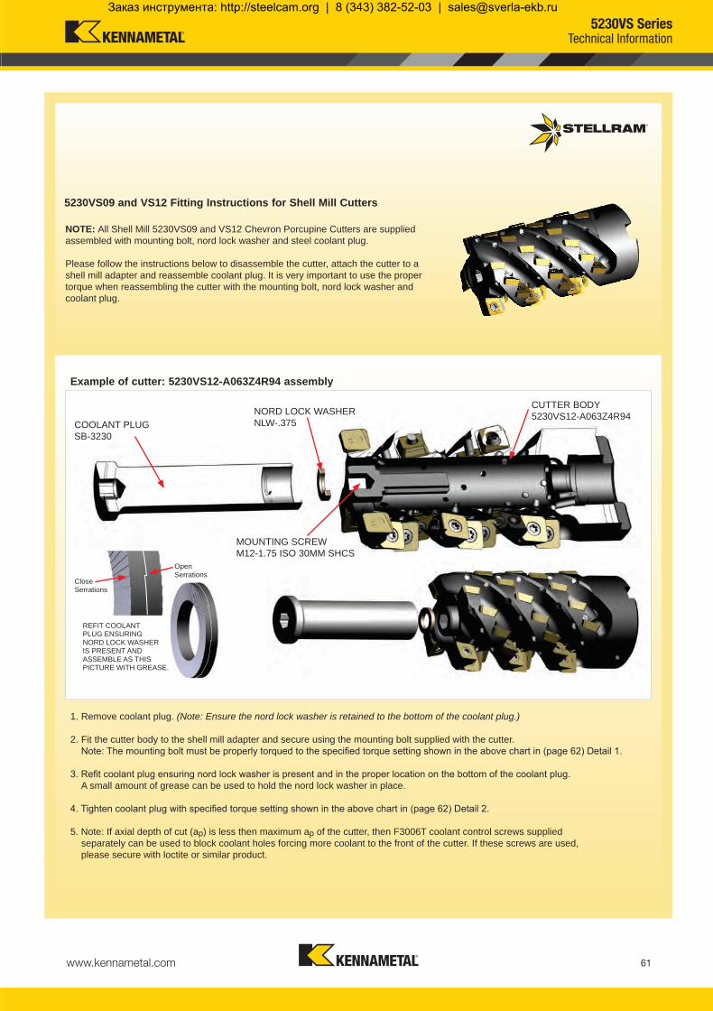
www.kennametal.com 61
1. Remove coolant plug. (Note: Ensure the nord lock washer is retained to the bottom of the coolant plug.)
2. Fit the cutter body to the shell mill adapter and secure using the mounting bolt supplied with the cutter. Note: The mounting bolt must be properly torqued to the specified torque setting shown in the above chart in (page 62) Detail 1.
3. Refit coolant plug ensuring nord lock washer is present and in the proper location on the bottom of the coolant plug. A small amount of grease can be used to hold the nord lock washer in place.
4. Tighten coolant plug with specified torque setting shown in the above chart in (page 62) Detail 2.
5. Note: If axial depth of cut (ap) is less then maximum ap of the cutter, then F3006T coolant control screws supplied separately can be used to block coolant holes forcing more coolant to the front of the cutter. If these screws are used, please secure with loctite or similar product.
MOUNTING SCREWM12-1.75 ISO 30MM SHCS
REFIT COOLANT PLUG ENSURING NORD LOCK WASHER IS PRESENT AND ASSEMBLE AS THIS PICTURE WITH GREASE.
Close Serrations
Open Serrations
COOLANT PLUGSB-3230
NORD LOCK WASHERNLW-.375
CUTTER BODY5230VS12-A063Z4R94
Example of cutter: 5230VS12-A063Z4R94 assembly
5230VS09 and VS12 Fitting Instructions for Shell Mill Cutters
NOTE: All Shell Mill 5230VS09 and VS12 Chevron Porcupine Cutters are supplied assembled with mounting bolt, nord lock washer and steel coolant plug.
Please follow the instructions below to disassemble the cutter, attach the cutter to a shell mill adapter and reassemble coolant plug. It is very important to use the proper torque when reassembling the cutter with the mounting bolt, nord lock washer and coolant plug.
5230VS SeriesTechnical Information
KMST-009_ExpFocusBroMetricUK_48-IBC.indd 61 4/25/14 4:36 PM
Заказ инструмента: http://steelcam.org | 8 (343) 382-52-03 | [email protected]

www.kennametal.com62
5230VS09-A050Z4R51 M12-1.75 ISO x 30mm SHCS 80 100 SB-3413 345230VS09-A050Z4R80 SB-3621
5230VS12-A063Z4R57 M12-1.75 ISO x 30mm SHCS 80 100 SB-3229 345230VS12-A063Z4R94 SB-3230
5230VS12-A080Z5R65 M16-2 ISO x 40mm SHCS 110 150 SB-3231 615230VS12-A080Z5R110 SB-3232
5230VS12-A100Z6R76 M20-2.5 ISO x 50mm SHCS 120 180 SB-3233 615230VS12-A100Z6R133 SB-3234
5230VS12 Detail 1 Detail 2
Cutter Mounting BoltDescription
**Torque Values in Nm for Mounting BoltCoolant PlugDescription
Coolant Plugtightening
NmNormalCondition
ExcessiveCondition
5230VS09 Detail 1 Detail 2
Cutter Mounting BoltDescription
**Torque Values in Nm for Mounting BoltCoolant PlugDescription
Coolant Plugtightening
NmNormalCondition
ExcessiveCondition
Torque values for mounting bolts Excessive condition is when long reach extensions are required or when cutting parameters are elevated to extreme parameters.
5230VS Technical Information
Hex Keys
M12 = Hex Key Size 10M16 = Hex Key Size 14M20 = Hex Key Size 17
KMST-009_ExpFocusBroMetricUK_48-IBC.indd 62 4/25/14 4:36 PM
Заказ инструмента: http://steelcam.org | 8 (343) 382-52-03 | [email protected]

www.kennametal.com 63
P P M M K N S H
K
P P K
M S
M M S
S
P P M M S
P P K
Material Guide – Key to Recommended InsertsMaterial Designation
Alloyed Steels PH Stainless Aluminum & Alloys High Temp. Alloys Hard MaterialsUnalloyed Steels Stainless Steels Cast Irons
5230 Geometries
5230 Grades
-41This general purpose utility geometry has a positive cutting action and reinforced cutting edge for medium roughing and semi-finishing applications.
-422This positive geometry features an 11º chip angle and an “E” edge preparation for roughing and semi- finishing applications in difficult to machine materials.
X500
MP91M
Coating Type: CVD, TiN-TiC-TiN, X-Grade™ Technology
High level of shock resistance; operates at the low to medium cutting speeds; high metal removal rates while retaining a secure cutting edge.
Coating Type: CVD, TiN-MT-TiCN-Al2O3
With its Aluminium Oxide coating, this grade is recommended every time wear characteristics are more important than toughness.
-423A strong positive geometry featuring a smaller primary angle and a small controlled hone to reduce cutting pressures, followed by a higher secondary angle to allow free cutting of the chip without rubbing on the insert rake face. Chip flow compresses the chip for easy evacuation.
SP6519 Coating Type: PVD, TiAlN
This grade features a combination of a tough substrate with a new generation of TiAlN super nano coating, making it virtually free of residual stress and extremely hard for unmatched performance.
-TNThis geometry is a flat top design with a strong T-land edge preparation for preventing chipping in unstable conditions. It has a smaller edge preparation which reduces machine power consumption.
5230 Geometries & Grades
KMST-009_ExpFocusBroMetricUK_48-IBC.indd 63 4/25/14 4:36 PM
Заказ инструмента: http://steelcam.org | 8 (343) 382-52-03 | [email protected]

www.kennametal.com64
KMST-009_ExpFocusBroMetricUK_48-IBC.indd 64 4/25/14 4:36 PM
Заказ инструмента: http://steelcam.org | 8 (343) 382-52-03 | [email protected]

www.kennametal.com 65
5505 Ball Nose Contour Milling
Contour Milling of Mild Steels to High Temperature Superalloys
KMST-009_ExpFocusBroMetricUK_48-IBC.indd 65 4/25/14 4:36 PM
Заказ инструмента: http://steelcam.org | 8 (343) 382-52-03 | [email protected]

www.kennametal.com66
5505VX State of the Art Ball Nose Cutters
• Reinforced design for heavy machining
• High volume of chip cutting
• Excellent chip control and evacuation
Weldon20mm – 50mm
Cylindrical 16mm – 32mm
Modular16mm – 32mm
5505VX Ball Nose Cutters are ideal for roughing and semi-finishing of profiles and complex contours in Steel, Alloyed Steel, Stainless Steel, High Temperature Alloys and Cast Iron.
• One grade, one geometry does it all
• Helical insert design and rigid fixation for increased speeds and feeds
• Double edge insert is indexable for reduced inventory
• Slotting to full radius
Case HistoryMaterial: Stainless Steel 403 Cutter: 5505VX (25mm Cutter)Component: Turbine Blade Industry: Power Generation Insert Grade: SP6519 RPM: 2293Cutting Speed Vc: 183 m/minFeed per Tooth fz: 0,28mmFeed Rate: 1285 mm/minDepth of cut ap: 3,18mm
40% Increase in Productivity
5505 Ball Nose Contour Mills
KMST-009_ExpFocusBroMetricUK_48-IBC.indd 66 4/25/14 4:36 PM
Заказ инструмента: http://steelcam.org | 8 (343) 382-52-03 | [email protected]

www.kennametal.com 67
5505VX Heavy Duty Ball Nose Cutters
Modular system absorbs vibrations under high length/diameter ratio
One insert geometry for all materials
Helical insert design for increased speeds & feeds
Indexable double edge insert
Strong thick inserts ideal for medium to heavy roughing
Periphery ground insert generates a perfect radius size from the top to the center without facet during slotting
Axial retention screw for added security
5505 Ball Nose Contour Mills
KMST-009_ExpFocusBroMetricUK_48-IBC.indd 67 4/25/14 4:36 PM
Заказ инструмента: http://steelcam.org | 8 (343) 382-52-03 | [email protected]

www.kennametal.com68
030849 5505VX16SA016R25 16 25 M8 8.5 16 2 031448 FP3006T 031451 TP8 1,80030850 5505VX20SA020R35 20 35 M10 10.5 20 2 030672 FP3007T 031451 TP8 1,80030851 5505VX25SA025R40 25 40 M12 12.5 25 2 015262 D4010T 015240 T15 3,10030852 5505VX32SA032R50 32 50 M16 17.0 32 2 015266 D5013T 015241 T20 6,00
032133 5505VX20WA020R34 20 106 34 25 20 2 030672 FP3007T 031451 TP8 1,80030840 5505VX25WA025R60 25 116 60 25 25 2 015262 D4010T 015240 T15 3,10032132 5505VX25WA025R69 25 150 69 32 25 2 015262 D4010T 015240 T15 3,10030842 5505VX32WA032R75 32 130 75 32 32 2 015266 D5013T 015241 T20 6,00030843 5505VX32WA032R100 32 160 100 32 32 2 015266 D5013T 015241 T20 6,00030844 5505VX40WA040R100 40 170 100 40 40 2 029640 D6014T 015241 T20 10,50030845 5505VX40WA040R150 40 220 150 40 40 2 029640 D6014T 015241 T20 10,50030846 5505VX50WA050R100 50 170 100 40 50 2 029641 F8017S 018288 KH5005 24,50030847 5505VX50WA050R150 50 230 150 50 50 2 029641 F8017S 018288 KH5005 24,50 030982 5505VX16CA20/016R30 16 180 30 20 16 2 031448 FP3006T 031451 TP8 1,80030983 5505VX20CA25/020R40 20 200 40 25 20 2 030672 FP3007T 031451 TP8 1,80030984 5505VX25CA025R55 25 250 55 25 25 2 015262 D4010T 015240 T15 3,10030985 5505VX25CA32/025R55 25 250 55 32 25 2 015262 D4010T 015240 T15 3,10030986 5505VX32CA032R65 32 250 65 32 32 2 015266 D5013T 015241 T20 6,00
D
L
I1
d1
D
L
I1
d1
D
M
L
D
d1
ap
Product Dimensions (mm) Spares
EDP Item Description D L/H M d1ap
maxNo. of Teeth EDP EDP
ScrewTightening
Nm
Product Dimensions (mm) Spares
EDP Item Description D L/H l1 d1ap
maxNo. of Teeth EDP EDP
ScrewTightening
Nm
5505VX Weldon Shank
5505VX Cylindrical Shank
5505VX Modular Head
Note: For cylindrical shank extensions in high density alloy with through coolant refer to page 74.
Depth of Cut (ap)
Modular Head
Cylindrical Shank
Weldon Shank
Note: Do not remove the radial screw; this is a fixed location for the insert see page 72.
5505VXBall Nose Milling Cutter
KMST-009_ExpFocusBroMetricUK_48-IBC.indd 68 4/25/14 4:42 PM
Заказ инструмента: http://steelcam.org | 8 (343) 382-52-03 | [email protected]

www.kennametal.com 69
032133 5505VX20WA020R34 - 85 - - - 34750030840 5505VX25WA025R60 - 85 - - - 30500032132 5505VX25WA025R69 - 85 - - - 30500030842 5505VX32WA032R75 - 85 - - - 23250030843 5505VX32WA032R100 - 85 - - - 23250030844 5505VX40WA040R100 - 85 - - - 17250030845 5505VX40WA040R150 - 85 - - - 17250030846 5505VX50WA050R100 - 85 - - - 17250030847 5505VX50WA050R150 - 85 - - - 17250030982 5505VX16CA20/016R30 - 85 - - - 54000030983 5505VX20CA25/020R40 - 85 - - - 34750030984 5505VX25CA025R55 - 85 - - - 30500030985 5505VX25CA32/025R55 - 85 - - - 30500030986 5505VX32CA032R65 - 85 - - - 23250030849 5505VX16SA016R25 - 85 - - - 54000030850 5505VX20SA020R35 - 85 - - - 34750030851 5505VX25SA025R40 - 85 - - - 30500030852 5505VX32SA032R50 - 85 - - - 23250
5505VX Technical Information (mm)Product Dimensions
EDP Item Description Facing Pitch
Ramping Angle °
Helical Hole min. - max.
ap max Helical /Linear
Max RPM
5505VXBall Nose Milling Cutter
Ramping
KMST-009_ExpFocusBroMetricUK_48-IBC.indd 69 4/25/14 4:42 PM
Заказ инструмента: http://steelcam.org | 8 (343) 382-52-03 | [email protected]

www.kennametal.com70
16 R-F SP6519 0,06 - 0,15 0,06 - 0,13 0,04 - 0,11 0,04 - 0,10 0,06 - 0,15 0,06 - 0,15 0,06 - 0,15 - - 0,04 - 0,08 0,04 - 0,08 0,04 - 0,08 0,04 - 0,10 - -20 R-F SP6519 0,06 - 0,17 0,06 - 0,15 0,04 - 0,13 0,04 - 0,12 0,06 - 0,17 0,06 - 0,17 0,06 - 0,17 - - 0,04 - 0,10 0,04 - 0,10 0,04 - 0,10 0,04 - 0,12 - -25 R-F SP6519 0,06 - 0,20 0,06 - 0,18 0,04 - 0,16 0,04 - 0,15 0,06 - 0,20 0,06 - 0,20 0,06 - 0,20 - - 0,04 - 0,13 0,04 - 0,13 0,04 - 0,13 0,04 - 0,15 - -32 R-F SP6519 0,06 - 0,22 0,06 - 0,20 0,04 - 0,18 0,04 - 0,17 0,06 - 0,22 0,06 - 0,22 0,06 - 0,22 - - 0,04 - 0,15 0,04 - 0,15 0,04 - 0,15 0,04 - 0,17 - -40 R-F SP6519 0,06 - 0,24 0,06 - 0,22 0,04 - 0,20 0,04 - 0,19 0,06 - 0,24 0,06 - 0,24 0,06 - 0,24 - - 0,04 - 0,17 0,04 - 0,17 0,04 - 0,17 0,04 - 0,19 - -50 R-F SP6519 0,06 - 0,27 0,06 - 0,25 0,04 - 0,23 0,04 - 0,22 0,06 - 0,27 0,06 - 0,27 0,06 - 0,27 - - 0,04 - 0,20 0,04 - 0,20 0,04 - 0,20 0,04 - 0,22 - -
030737 XPNT16/160308.R-F SP6519 - 7,40 17,40 3,18 8,00 0,04
030743 XPNT20/20T306.R-F SP6519 - 9,00 20,85 3,97 10,00 0,04
030746 XPNT25/250408.R-F SP6519 - 11,00 26,00 4,76 12,50 0,04
030749 XPNT32/320612.R-F SP6519 - 14,10 33,40 6,35 16,00 0,04
030755 XPNT40/40T716.R-F SP6519 - 18,00 41,84 7,95 20,00 0,04
030758 XPNT50/50T716.R-F SP6519 - 22,25 52,86 7,95 25,00 0,04
XPNT-F
Product Application & Material Dimensions (mm)
EDP Item Description Grade
Roughing Semi-Finishing Finishing
d (IC) l s r hm minDepth of Cut (mm)ap max.* ae / ap max. ae / ap max.
10% of the cutter diameter -
Machining Choice: 1st Choice 2nd Choice 3rd Choice | Material Guide Key descriptions found on page 73.
5505VX Feeds fz (mm/tooth)
Tool
Diam
eter
Geom
etry
Grad
e
Oper
ation
Unall
oyed
St
eel
Alloy
ed
Stee
l
Stain
less
Stee
l
Stain
less S
teel
Refra
ctory
PH
Gray
Iro
n
Sphe
roida
l- Du
ctile
Iron
Malle
able
Iron
Alum
inium
&
Alloy
s <1
6% S
i 116
HBN
Alum
inium
&
Silic
on
>16
% S
i 92 H
BN
HTA
Iron
Base
d Allo
ys
HTA
Coba
lt Ba
sed A
lloys
HTA
Nick
elBa
sed A
lloys
HTA
Titan
ium
Base
d Allo
ys
Hard
Stee
l>1
400 N
/mm2
>415
HBN
Chille
d Cas
t Iron
>140
0 N/m
m2
>400
HBN
Min. - Max. Min. - Max. Min. - Max. Min. - Max. Min. - Max. Min. - Max. Min. - Max. Min. - Max. Min. - Max. Min. - Max. Min. - Max. Min. - Max. Min. - Max. Min. - Max. Min. - Max.ContouringContouringContouringContouringContouringContouring
Note: HTA = High Temperature Alloys
Speed recommendations can be found on page 71.
* Note: ap max. is dependent on several insert sizes, see steel cutter page 84 for ap max.
5505VXMilling Inserts & Recommended Feeds
KMST-009_ExpFocusBroMetricUK_48-IBC.indd 70 4/25/14 4:42 PM
Заказ инструмента: http://steelcam.org | 8 (343) 382-52-03 | [email protected]

www.kennametal.com 71
P
130 - 295
115 - 260
100 - 230
75 - 175
50 - 110
M
115 - 270
105 - 235
50 - 120
K
140 - 295
110 - 240
100 - 220
N
S
23 - 55
22 - 48
25 - 55
36 - 79
H
Recommended Possible
Speed vc (m/min)
5505VX Series
Speed min. - max.
Coolant Recommendation PVDStandard
ISO Materials Rm and Hardness SP6519
UnalloyedSteel
<600 N/mm2
<180 HBN<950 N/mm2
<280 HBN
AlloyedSteel
700-950 N/mm2
200-280 HBN950-1200 N/mm2
280-355 HBN1200-1400 N/mm2
355-415 HBN
StainlessSteel
Austenitic + Ferritic300 seriesMartensitic400 series
PH Stainless RefractoryP.H.
Cast Iron
GreyGG-Ft
Spheroidal-DuctileGGG-FGSMalleable
GTS - MN/MP
Aluminium & Alloys
Aluminium & Alloys < 16% Si 116 HBN
Aluminium + Silicon > 16% Si 92 HBN
HighTemperature
Alloys
Iron Based
Cobalt Based
Nickel Based
Titanium Based
Hard Materials
Hard Steel>1400 N/mm2
>415 HBNChilled Cast Iron
>1400 N/mm2 > 400 HBN
5505VXRecommended Speeds
KMST-009_ExpFocusBroMetricUK_48-IBC.indd 71 4/25/14 4:42 PM
Заказ инструмента: http://steelcam.org | 8 (343) 382-52-03 | [email protected]

www.kennametal.com72
ap
De
r
5505VX Technical Information
5505VX Technical Information
Please do not try to remove this screw. This screw is glued into the body to keep the inserts in the correct position.
To find programmed feedrate: fz
where: fz = Feed per tooth hm = Average chip thickness r = Insert radius
ae = Radial Depth of Cut ap = Axial Depth of Cut
Average chip thickness: hm
hm fz =
r2 - r - ap r
( )2r2 - r - ae r
( )2
x
hm = fz x xr2 - r - ap r
( )2r2 - r - ae r
( )2
Working Diameter:
where: De = Working Diameter r = Cutter radius ap = Axial Depth of Cut
De = 2 x r2 - (r -ap)2
5505VXTechnical Information
KMST-009_ExpFocusBroMetricUK_48-IBC.indd 72 4/25/14 4:42 PM
Заказ инструмента: http://steelcam.org | 8 (343) 382-52-03 | [email protected]

www.kennametal.com 73
P P M M K N S H
P P M M K S
P P M M K S
Material Guide – Key to Recommended InsertsMaterial Designation
Alloyed Steels PH Stainless Aluminum & Alloys High Temp. Alloys Hard MaterialsUnalloyed Steels Stainless Steels Cast Irons
Ball Nose Geometry
Ball Nose Grade
SP6519
-F
Coating Type: PVD, TiAlN
The combination of a tough substrate with a new generation of TiAlN super nano coating, makes this new PVD coating virtually free of residual stress and extremely hard for unmatched performance.
Primarily used in Stainless Steel, High Temperature Alloys & Titanium with stable conditions. Also can be used in Steel, Steel Alloys and Cast Irons.
This geometry is a roughing ball nose fully ground insert for roughing and semi-finishing of all materials except Aluminium. This geometry is designed with chip grooves for better chip control.
Material: Titanium 6-4 Component: Valve Body Industry: Oil & Gas Cutter: 5505VX (25mm Cutter)Insert Grade: SP6519 RPM: 1469Cutting Speed Vc: 115 m/minFeed per Tooth fz: 0,135mmFeed Rate: 395,3 mm/min Depth of cut ap: 1,5mm
Case History
Helical Interpolation Doubled Productivity
5505 Ball Nose Contour Mills
KMST-009_ExpFocusBroMetricUK_48-IBC.indd 73 4/25/14 4:42 PM
Заказ инструмента: http://steelcam.org | 8 (343) 382-52-03 | [email protected]

www.kennametal.com74
D
L
D2
D1
L1
030624 M-13-M8-CA16-090 90 40 16 13 8,50 M8030625 M-13-M8-CA16-110 110 60 16 13 8,50 M8030626 M-13-M8-CA16-130 130 80 16 13 8,50 M8030627 M-13-M8-CA16-170 170 120 16 13 8,50 M8030628 M-18-M10-CA20-110 110 60 20 18 10,50 M10030629 M-18-M10-CA20-130 130 80 20 18 10,50 M10030630 M-18-M10-CA20-170 170 120 20 18 10,50 M10030631 M-18-M10-CA20-190 190 140 20 18 10,50 M10030632 M-21-M12-CA25-131 131 75 25 21 12,50 M12030633 M-21-M12-CA25-156 156 100 25 21 12,50 M12030634 M-21-M12-CA25-181 181 125 25 21 12,50 M12030635 M-21-M12-CA25-206 206 150 25 21 12,50 M12030636 M-21-M12-CA25-231 231 175 25 21 12,50 M12030637 M-29-M16-CA32-160 160 100 32 29 17,00 M16030638 M-29-M16-CA32-210 210 150 32 29 17,00 M16030639 M-29-M16-CA32-260 260 200 32 29 17,00 M16030640 M-29-M16-CA32-310 310 250 32 29 17,00 M16
Product Dimensions (mm)
EDP Item Description L L1 D2 D D1 M
Technical Advice
M Modular adapter 13 Diameter in front of the modular shank (D) M8 Metric Thread (M) CA16 Cylindrical shank diameter 16mm with through coolant 90 Total length of the body
Shank Extension
Cylindrical shank extensions can be used with all modular heads found in several product family series within this catalogue.
These extensions have the industry standard of metric threads.
Note: Order example with cylindrical shank: M-13-M8-CA16-090
Cylindrical Shank Extensions for Modular HeadsAnti-Vibration Tungsten Alloy with Through Coolant
KMST-009_ExpFocusBroMetricUK_48-IBC.indd 74 4/25/14 4:43 PM
Заказ инструмента: http://steelcam.org | 8 (343) 382-52-03 | [email protected]

www.kennametal.com 75
5720 Patented Profile Pocket Milling: Aluminium
Taking extreme high speed aluminium machining to the highest level
KMST-009_ExpFocusBroMetricUK_48-IBC.indd 75 4/25/14 4:44 PM
Заказ инструмента: http://steelcam.org | 8 (343) 382-52-03 | [email protected]

www.kennametal.com76
5720 Patented Series High Speed Aluminium Cutters
Extreme Metal Removal to fit your application • Especially designed for machining pockets and profiles on
Aluminium and Aluminium Alloys
• The 5720 is designed, manufactured and tested in accordance with EN ISO 15641:2001 to ensure maximum stability in high speed applications
• Each features internal coolant allowing better chip evacuation and higher feed rates
• The pockets are reinforced to allow for heavy feeding and safe ramping during machining
• Excellent tools for thin-walled machining
• HSK specials available upon request
Cylindrical Shank and special HSK Integral Shanks are balanced to G6.3 @ 30000 RPM for diameters up to 50mm. Diameters larger than 50mm are balanced to G6.3 @ 24000 RPM.
5720 inserts: 12 different radii are available, each with the same cutting depth capacity of 16mm
5720 Up to 51000 RPMCylindrical25mm – 32mm
Shell40mm – 80mm
Modular25mm – 32mm
5720 Profile Pocket Milling: Aluminium
KMST-009_ExpFocusBroMetricUK_48-IBC.indd 76 4/25/14 4:44 PM
Заказ инструмента: http://steelcam.org | 8 (343) 382-52-03 | [email protected]

www.kennametal.com 77
Internal coolant for maximum chip evacuation
Inserts with different radii are held without losing any gauge height of the cutter length
12 different insert radii are available, each with a 16mm cutting depth
5720 Patented Series Extreme High Speed Aluminium Cutters
Cylindrical Shank designed and balanced to G6.3 at 30000 RPM
Capable of operating up to 51000 RPM
Flute engineered for maximum chip evacuation
Excellent tool for thin-walled machining
5720 Profile Pocket Milling: Aluminium
KMST-009_ExpFocusBroMetricUK_48-IBC.indd 77 4/25/14 4:44 PM
Заказ инструмента: http://steelcam.org | 8 (343) 382-52-03 | [email protected]

www.kennametal.com78
034616 5720VZ16SA025Z2R50 25 50 M12 12,50 16 2 030820 DP5009A 030819 TP20 6,00034618 5720VZ16SA032Z2R50 32 50 M16 17 16 2 030820 DP5009A 030819 TP20 6,00031639 5720VZ16SA032Z3R50 32 50 M16 17 16 3 030820 DP5009A 030819 TP20 6,00
034614 5720VZ16CA025Z2R75 25 131 75 25 16 2 030820 DP5009A 030819 TP20 6,00034617 5720VZ16CA032Z2R75 32 135 75 32 16 2 030820 DP5009A 030819 TP20 6,00034640 5720VZ16CA032Z3R75 32 135 75 32 16 3 030820 DP5009A 030819 TP20 6,00
034619 5720VZ16-A040Z03R 40 45 - 16 16 3 030820 DP5009A 030819 TP20 6,00031325 5720VZ16-A050Z03R 50 45 - 22 16 3 030820 DP5009A 030819 TP20 6,00031326 5720VZ16-A050Z04R 50 45 - 22 16 4 030820 DP5009A 030819 TP20 6,00031328 5720VZ16-A063Z05R 63 45 - 22 16 4 030820 DP5009A 030819 TP20 6,00031327 5720VZ16-A063Z04R 63 45 - 22 16 5 030820 DP5009A 030819 TP20 6,00031329 5720VZ16-A080Z04R 80 50 - 27 16 4 030820 DP5009A 030819 TP20 6,00031330 5720VZ16-A080Z05R 80 50 - 27 16 5 030820 DP5009A 030819 TP20 6,00
M
L
D
d1
H
D
D
L
I1
d1
d1
D
ap
Product Dimensions (mm) Spares
EDP Item Description D L/H M d1 ap max
No. of Teeth
Insert radius range EDP EDP
ScrewTightening
Nm*
Product Dimensions (mm) Spares
EDP Item Description D L/H l1 d1 ap max
No. of Teeth
Insert radius range EDP EDP
ScrewTightening
Nm*
5720VZ16 Cylindrical Shank - Coarse and Medium Pitch Facet to 6,00Facet to 6,00Facet to 6,00
5720VZ16 Shell Mill Fixation - Coarse and Medium Pitch Facet to 6,00Facet to 6,00Facet to 6,00Facet to 6,00Facet to 6,00Facet to 6,00Facet to 6,00
5720VZ16 Modular Head - Coarse and Medium Pitch Facet to 6,00Facet to 6,00Facet to 6,00
Cylindrical Shank
Modular Head
Shell Mill Fixation
Depth of Cut (ap)
Note: For cylindrical shank extensions in high density alloy with through coolant refer to page 74.
* It is important to change the screw each time the insert is changed to ensure the highest security. A dynamometric key and the right torque value are important. See above for the correct torque information.
* It is important to change the screw each time the insert is changed to ensure the highest security. A dynamometric key and the right torque value are important. See above for the correct torque information.
5720VZ16Profiling / Pocketing Milling Cutters
KMST-009_ExpFocusBroMetricUK_48-IBC.indd 78 4/25/14 4:44 PM
Заказ инструмента: http://steelcam.org | 8 (343) 382-52-03 | [email protected]

www.kennametal.com 79
034614 5720VZ16CA025Z2R75 25 14.5* 29,5 48,0 4,00 50000034617 5720VZ16CA032Z2R75 32 11.4* 43,5 62,0 4,00 41500034640 5720VZ16CA032Z3R75 32 11.4* 43,5 62,0 4,00 41500034619 5720VZ16-A040Z3R 40 7.6* 59,5 78,0 4,00 36500031325 5720VZ16-A050Z03R 50 7.9* 79,5 98,0 4,00 30000031326 5720VZ16-A050Z4R 50 7.9* 79,5 98,0 4,00 30000031328 5720VZ16-A063Z05R 63 5.9* 105,5 124,0 4,00 26000031327 5720VZ16-A063Z4R 63 5.9* 105,5 124,0 4,00 26000031329 5720VZ16-A080Z04R 80 4.4* 139,5 158,0 4,00 23000031330 5720VZ16-A080Z05R 80 4.4* 139,5 158,0 4,00 23000034616 5720VZ16SA025Z2R50 25 14.5* 29,5 48,0 4,00 50000034618 5720VZ16SA032Z2R50 32 11.4* 43,5 62,0 4,00 41500031639 5720VZ16SA032Z3R50 32 11.4* 43,5 62,0 4,00 41500
5720VZ Technical Information (mm)Product Dimensions
EDP Item Description Facing Pitch
Ramping Angle °
Helical Hole min. - max.
ap max Helical /Linear
Max RPM
* Max. ramping angle for insert is calculated with facet
Find the different ramping angles for all available insert radii on technical information page 81.
Radial depth of cut 0,20mm up to full cutter diameter.
These tools have been designed, manufactured and tested in accordance with EN ISO standard 15641:2001.
These tools are stocked without an electronic chip.
Note: If using a insert with radius, then the facing pitch for the 5702VZ cutter is equal to the cutting diameter (D) minus 2 x chosen radius.
Cylindrical Shanks or Special HSK Integral Shanks are designed and balanced to G6.3 at 30,000 RPM for diameters 50mm and below. Diameters larger then 50mm are balanced to G6.3 at 24,000 rpm.
Cylindrical Shank tools mounted in a shrink fit holder or any other mill chuck holder + inserts + screws must be re-inspected for balance as an assembly by the end user when at or exceeding 8,000 rpm. End user must balance the assembly to a G6.3 value minimum.
Shell Mills and Modular Heads are not balanced. These tools must be re-inspected for balance as an assembly, cutter + adapter + inserts + screws by the end user when at or exceeding 8,000 rpm. End user must balance the assembly to a G6.3 value minimum.
Additional Balancing and Torque values can be found in the technical section pages 82.
5720VZ16Profiling / Pocketing Milling Cutters
Ramping Helical Interpolation
Facing Pitch
Flat
KMST-009_ExpFocusBroMetricUK_48-IBC.indd 79 4/25/14 4:44 PM
Заказ инструмента: http://steelcam.org | 8 (343) 382-52-03 | [email protected]

www.kennametal.com80
030927 ZDET16M5PDFR-721 GH1 11,30 22,92 5,00 0,02
031384 ZDET16M504FR-721 GH1 11,30 22,92 5,00 0,40 0,02
030928 ZDET16M508FR-721 GH1 11,30 22,92 5,00 0,80 0,02
031385 ZDET16M512FR-721 GH1 11,30 22,92 5,00 1,20 0,02
030929 ZDET16M516FR-721 GH1 11,30 22,92 5,00 1,60 0,02
030930 ZDET16M520FR-721 GH1 11,30 22,92 5,00 2,00 0,02
030931 ZDET16M525FR-721 GH1 11,30 22,92 5,00 2,50 0,02
030932 ZDET16M530FR-721 GH1 11,30 22,92 5,00 3,00 0,02
030933 ZDET16M532FR-721 GH1 11,30 22,92 5,00 3,20 0,02
030934 ZDET16M540FR-721 GH1 11,30 22,92 5,00 4,00 0,02
030935 ZDET16M550FR-721 GH1 11,30 22,92 5,00 5,00 0,02
030936 ZDET16M560FR-721 GH1 11,30 22,92 5,00 6,00 0,02
ZDET16-721l
rd s
14mm FR-721 GH1 0,02 - 0,25 0,02 - 0,20
N
400 - 3050
295 - 2440
Recommended Possible
Speed vc (m/min)
5720VZ Series
K10-K20/C3 - C2 ISO / ANSI
Speed min. - max.
Coolant RecommendationUncoated Micrograin
ISO Materials Rm and Hardness GH1
Aluminium & Alloys
Aluminium & Alloys < 16% Si 116 HBN
Aluminium + Silicon > 16% Si 92 HBN
5720VZ Feeds fz (mm/tooth)
Size
Geom
etry
Grad
e
Oper
ation
Alum
inium
&
Alloy
s <1
6% S
i 116
HBN
Alum
inium
&
Silic
on
>16
% S
i 92 H
BN
Min. - Max. Min. - Max.
Profile/ Pocketing
Product Application & Material Dimensions (mm)
EDP Item Description Grade
Roughing Semi-Finishing Finishing
d (IC) l s r hm minDepth of Cut (mm)ap max. ap min. - max. ap min. - max.
16* 1,00 - 5,00 0,20 - 1,00
Facet
Machining Choice: 1st Choice 2nd Choice 3rd Choice | Material Guide Key descriptions found on page 84.
* Max. possible ap of 16mm and ae the full diameter (depending on the application). * For Slotting applications with 5720VZ16 series please see recommendations for maximum ap on page 81 .
5720VZ16Milling Inserts, Recommended Feeds & Speeds
KMST-009_ExpFocusBroMetricUK_48-IBC.indd 80 4/25/14 4:44 PM
Заказ инструмента: http://steelcam.org | 8 (343) 382-52-03 | [email protected]

www.kennametal.com 81
25 2 156032 2 322632 3 205640 3 518450 3 792150 4 864163 4 1330763 5 1360980 4 1689880 5 21123
25,0 14.50 17.30 9.40 9.60 18.80 18.90 9.00 11.20 7.3032.0 11.40 11.90 11.90 12.20 12.40 12.40 13.10 13.80 13.4040,0 7.60 7.80 7.80 8.00 8.10 8.10 8.50 8.80 9.1050,0 7.90 7.20 7.30 7.90 7.60 7.60 8.90 9.00 9.2563,0 5.90 5.40 5.50 5.80 5.60 5.60 6.90 6.60 6.6580,0 4.40 4.00 4.10 4.30 4.20 4.20 5.10 4.80 4.90
25 2 7,5032 2 11,0032 3 6,0040 3 9,0050 3 11,0050 4 9,0063 4 11,0063 5 9,0080 4 11,0080 5 11,00
Possible Max. ap SlottingChart for maxium ap when slotting with 5720VZ16 series
Diameter (mm) No. of Inserts ap max (mm)
5720VZ16 Ramp Angle °Insert ZDET16M5…FR-721 (Radius mm)
Cutter Dia. (mm) PDFR to R1,20 R1,60 R2,00 R2,50 R3,00 R3,20 R4,00 R5,00 R6,00
Possible Metal RemovalCalculated with 24000 RPM
Cutter dia. Z Qcm3/min
fz = hm x
Calculation of the average chip thickness in relation with the ae (Radial Engagement) if ae is less than 50% of Dia.
hm = fz x
Formula: Average Chip Thickness (hm)hm = Average chip thicknessae = Radial engagementfz = Feed per toothd = Cutter diameter
Formula: Programme Feed Rate (fz)
The chart above shows total metal removal capacity (based on 24,000 RPM) by cutter diameter and number of teeth.
The maximum RPM is engraved on all cutter bodies.
ap max in connection with: The cutter diameter, rigidity of the cutter, rigidity of the machine and the size of the flute.
ae
ddae
5720VZ16Technical Information
KMST-009_ExpFocusBroMetricUK_48-IBC.indd 81 4/25/14 4:44 PM
Заказ инструмента: http://steelcam.org | 8 (343) 382-52-03 | [email protected]
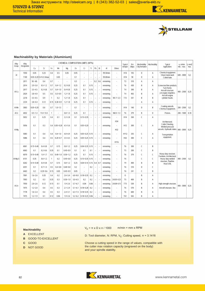
www.kennametal.com82
Al1050 0.05 0.25 0.4 0.5 0.05 0.05 - - - - - H14 105 D A
600 - 3000 0,21100 0.05~0.20 Si+Fe1.0max 0.05 - 0.1 - - - - - H14 90 D A
Al-Cu
2011 50.~60. 0.4 0.7 - - 0.3 - - 0.2 0.6 - T3 310 A A
400 - 2500 0,25
2014 3.9~5.0 0.5~1.2 0.7 0.4~1.2 0.2~0.8 0.25 0.1 0.15 - - - T6 430 B A
2017 3.5~4.5 0.2~0.8 0.7 0.4~1.0 0.4~0.8 0.25 0.1 0.15 - - - T4 390 B A
2024 3.8~4.9 0.5 0.5 0.3~0.9 1.2~1.8 0.25 0.1 0.15 - - - T4 465 B A
2218 3.5~4.5 0.9 1 0.2 1.2~1.8 0.25 0.1 - - - Ni1.7~2.3 T72 331 B B
2224 3.8~4.4 0.12 0.15 0.30~0.9 1.2~1.8 0.25 0.1 0.15 - - - A A
Al-Mn 3003 0.05~0.20 0.6 0.7 1.0~1.5 - 0.1 - - - - - H14 140 D B 200 - 2500 0,2
Al-Si 4032 0.5~1.3 11.0~13.5 1 - 0.8~1.3 0.25 0.1 - - - Ni0.5~1.3 T6 379 B D 200 - 1000 0,18
Al-Mg
5052 0.1 0.25 0.4 0.1 2.2~2.8 0.1 0.15~0.35 - - - - H14 260 C A
400 - 3000 0,25
H34
5056 0.1 0.3 0.4 0.05~0.20 4.5~5.6 0.1 0.05~0.20 - - - - H12 300 C A
H32
5083 0.1 0.4 0.4 0.4~1.0 4.0~4.9 0.25 0.05~0.25 0.15 - - - H112 335 C A
5086 0.1 0.4 0.5 0.20~0.7 3.5~4.5 0.25 0.05~0.25 0.15 - - - H32 300 C A
H116
Al-Mg-Si
6061 0.15~0.40 0.4~0.8 0.7 0.15 0.8~1.2 0.25 0.04~0.35 0.15 - - - T6 300 C B
400 - 2500 0,2
6063 0.1 0.2~0.6 0.35 0.1 0.45~0.9 0.1 0.1 0.1 - - - T5 200 C B
6070 0.15~0.40 1.0~1.7 0.5 0.40~1.0 0.50~1.2 0.25 0.1 0.15 - - - T6 379 C C
6151 0.35 0.6~1.2 1 0.2 0.45~0.8 0.25 0.15~0.35 0.15 - - - T6 C C
6262 0.15~0.40 0.4~0.8 0.7 0.15 0.8~1.2 0.25 0.04~0.14 0.15 0.4 0.7 - T9 400 B B
6351 0.1 0.7~1.3 0.5 0.4~0.8 0.40~0.8 0.2 - 0.2 - - - T6 310 D C
6463 0.2 0.20~0.6 0.15 0.05 0.45~0.9 0.05 - - - - - T6 241 C B
Al-Zn
7001 1.6~2.6 0.35 0.4 0.2 2.6~3.4 6.8~8.0 0.18~0.35 0.2 - - - O B A
400 - 3000 0,25
7003 0.2 0.3 0.35 0.3 0.50~1.0 5.0~6.5 0.2 0.2 - - Zr0.05~0.25 T5 400 B A
7050 2.0~2.6 0.12 0.15 0.1 1.9~2.6 5.7~6.7 0.04 0.06 - - Zr0.08~0.15 T73 530 B A
7075 1.2~2.0 0.4 0.5 0.3 2.1~2.9 5.1~6.1 0.18~0.28 0.2 - - - T6 570 B A
7178 1.6~2.4 0.4 0.5 0.3 2.4~3.1 6.3~7.3 0.18~0.35 0.2 - - - T6 600 B A
7475 1.2~1.9 0.1 0.12 0.06 1.9~2.6 5.2~6.2 0.18~0.25 0.06 - - - T61 565 B A
Machinability by Materials (Aluminium)
99.50min Chemical equipment Sheet metal work
Coiled tube99.00min
remaining
Screw machine products. Tuck frame.
Aircraft structure. Jet engine impellers.
Aircraft engine cylinder heads.
remaining
remaining
remaining
remaining
remaining
remaining Cooking utensils. Chemical equipment.
remaining Pistons.
remaining
Architectural. Cable Sheeting. Welded pressure
vessels. Hydraulic tubes.
remaining
remaining Transportation equipment.remaining
remaining
Heavy duty structure.Furniture. Architectural.
Heavy duty weldedstructure. Pipeline.
Heat Sink.
remaining
remaining
remaining
remaining
remaining
remaining
remaining
remaining
remaining High strength structure.
remaining Aircraft structure. Bat.
remaining
remaining
Alloy Group
Alloy Designation
CHEMICAL COMPOSITION LIMITS (WT%) Typical tremper
Rm (Mpa)
Machinability Chip formation
Machinability Typical Applications
vc m/min min. - max.
fz mm/Z max.
Cu Si Fe Mn Mg Zn Cr Ti Pb Bi Al Others
MachinabilityA EXCELLENTB GOOD-TO-EXCELLENTC GOODD NOT GOOD
D: Tool diameter, N: RPM, Vc: Cutting speed, π = 3.1416
Choose a cutting speed in the range of values, compatible with the cutter max rotation capacity (engraved on the body) and your spindle stability.
Vc = π x D x n / 1000 m/min = mm x RPM
5702VZD & 5720VZTechnical Information
KMST-009_ExpFocusBroMetricUK_48-IBC.indd 82 4/25/14 4:45 PM
Заказ инструмента: http://steelcam.org | 8 (343) 382-52-03 | [email protected]

www.kennametal.com 83
M6 10
M8 30
M10 50
M12 80
M16 110
M6 13 10
M8 16 30
M10 22 50
M12 27 80
M16 32 110
M20 40 120
Thread sizes (mm)
Cutter BoreSize (mm)
Torque ValuesNm
Thread sizes(mm)
Torque ValuesNm
The Cutter Nomenclature Code:
Tighten the Modular Head to the Extension, with lubricant, apply the torque value of:
Tighten the bolt between the shell mill and tool holder, with lubricant apply the torque value of:
Cylindrical shanks & HSK shanks (special): 5702VZD14 and 5720VZ16 are designed and balanced to G6.3 at 30,000 rpm for diameters 50mm and below. Diameters larger then 50mm are balanced to G6.3 at 24,000 rpm. Cylindrical shank tools mounted in a shrink fit holder or any other mill chuck holder + inserts + screws must be re-inspected for balance by the end user when exceeding 8,000 rpm. End user must balance the assembly to a G6.3 value minimum.
Shell Mills and Modular Heads: 5720VZ16 Shell Mills and Modular Heads are not balanced. These tools must be re-inspected for balance as an assembly, cutter + adapter + inserts + screws by the end user when at or exceeding 8,000 rpm. End user must balance the assembly to a G6.3 value minimum.
Balancing requires removing some material by drilling or milling operations. To avoid making modular heads weaker, limit these operations by avoiding high rpm.
For each new modular head added to the same extension, re-balance the assembly. For each new Shell Mill installed on the same toolholder, re-balance the assembly.
5702 = Stellram Product Family V = Screw fixation Z = Insert shape (parallelogram) D = ISO insert clearance (D = 15°) 14 = Insert edge length (mm) C = Plain straight shank (No flats) A = Through the tool coolant 020 = Cutting diameter (mm) R = Right hand tool 58 = Reach of tool in mm -2 = Maximum value of the insert radius in 1/10mm increments
This tool must only be used for the following applications: Face milling, shoulder milling, slotting and pocketing.
Example: 5702VZD14CA020R58-2
Recommendations for High Speed Machiningat 8,000 rpm or above.
• Check spindle condition: Runout Balancing Clamping of the attachment in traction Marking and cleanliness
• Check that the tool is suitable for the required use.
• Inserts must be locked positively in the pocket and secured using the torx screw provided. The screw must be torqued to the correct value as indicated in our charts on the steel product page 78. For security use a new screw each time.
• Check the balancing of the – assembled tool – cutter body, inserts and attachment.
• Before start up, note the maximum RPM engraved on the tool or in our technical documents. The maximum RPM is linked to a precise balancing value.
• Ensure that the field of application of the tool shown in our technical documents and technological parameters is observed: ae (mm) width of cut, lateral engagement (radial) ap (mm) Axial depth of cut fz (mm/tooth) Feed per tooth n (rpm) RPM
Stellram cannot accept responsibility for misuse of this product: • Non observance of the above instructions • Machine without casing • Incorrect clamping of workpieces • No safety device on the machine • Any misuse or incorrect clamping
The optimum rotation must be determined by condition of the spindle. The spindle must be rigid to run at these higher RPMs.
Under no circumstances must any attempt be made to repair this tool. The only permitted maintenance is the indexing or replacement of the inserts. Use a new screw for each insert replacement.
When assembling the cutter to a shrink fit holder, the maximum protrusion can not exceed 10% of the reach of tool.
5702VZD & 5720VZTechnical Information
KMST-009_ExpFocusBroMetricUK_48-IBC.indd 83 4/25/14 4:45 PM
Заказ инструмента: http://steelcam.org | 8 (343) 382-52-03 | [email protected]

www.kennametal.com84
P P M M K N S H
N
N
Material Guide – Key to Recommended InsertsMaterial Designation
Alloyed Steels PH Stainless Aluminum & Alloys High Temp. Alloys Hard MaterialsUnalloyed Steels Stainless Steels Cast Irons
5720 High Speed Geometry
High Speed Grade
GH1
-721
Uncoated, Micrograin
This micrograin grade is designed for use on Aluminium Alloys, Copper, Brass and Kevlar etc. The grade GH1 works well with or without coolant with low cutting pressure at high speeds due to sharp cutting edge.
This extreme high positive geometry is highly suitable for machining Aluminium Alloys, Copper and Brass. This geometry is periphery ground with a pressed, polished top rake face reducing built up edge. Especially qualified when machining thin-walled components.
Material: Aluminium 2024 Cutter: 5720VZ (32mm Cutter)Component: Seat Support Industry Segment: Aerospace Insert Grade: GH1 Spindle Speed: 17,491 RPM Cutting Speed Vc: 1758 m/min Feed per Tooth fz: 0,25mmFeed rate: 8745 mm/min Depth of Cut: 2,5mm
Result: 400% Increase in Productivity
5720 Case History
5702VZD & 5720VZTechnical Information
KMST-009_ExpFocusBroMetricUK_48-IBC.indd 84 4/25/14 4:45 PM
Заказ инструмента: http://steelcam.org | 8 (343) 382-52-03 | [email protected]

www.kennametal.com 85
5702 High Speed Aluminium Cutters
Outstanding performance in a 20mm cutter
KMST-009_ExpFocusBroMetricUK_48-IBC.indd 85 4/25/14 4:45 PM
Заказ инструмента: http://steelcam.org | 8 (343) 382-52-03 | [email protected]

www.kennametal.com86
5702 Series High Speed Aluminium Cutters
Extreme Metal Removal to fit your application • Especially designed for machining pockets and profiles on
Aluminium and Aluminium Alloys
• Desiged, manufactured and tested in accordance with EN ISO 15641:2001 to ensure maximum stability in high speed applications
• Through-tool coolant allowing better chip evacuation and higher feed rates
• Pockets are reinforced to allow for heavy feeding and safe ramping during machining
• Excellent tools for thin-walled machining
• HSK specials available upon request
• 12mm depth of cut
• 5 radii available
• -701 fully ground geometry ideal for high speed Aluminium milling
• Balanced to G6.3 @ 30000 RPM
5702 Up to 43000 RPM Cylindrical20mm
Material: Aluminium Alloy 7175Component: AirframeIndustry Segment: AerospaceTool: 5702VZD (20mm Cutter)Insert Grade: GH2Cutting Speed Vc: 754 m/minSpindle Speed: 12000 RPMFeed per Tooth fz: 0,25mmFeedrate: 6000 mm/min Precision inserts provide excellent results in thin-wall machining applications while yielding superior surface finishes
5702 Case History
5702 High Speed Aluminium Cutter
KMST-009_ExpFocusBroMetricUK_48-IBC.indd 86 4/25/14 4:45 PM
Заказ инструмента: http://steelcam.org | 8 (343) 382-52-03 | [email protected]

www.kennametal.com 87
P P M M K N S H
N N
Material Guide – Key to Recommended InsertsMaterial Designation
Alloyed Steels PH Stainless Aluminum & Alloys High Temp. Alloys Hard MaterialsUnalloyed Steels Stainless Steels Cast Irons
5702 Grade5702 Geometry
GH1 -701 Uncoated, Micrograin
This micrograin grade is designed for use on Aluminium Alloys, Copper, Brass and Kevlar, etc. The grade GH1 works well with or without coolant with low cutting pressure at high speeds due to sharp cutting edge.
This extreme high positive geometry is highly suitable for machining Aluminium Alloys, Copper and Brass. The -701 geometry is precision ground and gives excellent performance when machining thin-walled components.
5702 Precision High Speed Aluminium Cutter
Cylindrical Shank designed and balanced to G6.3 at 30000 RPM
Capable of operating up to 43000 RPM
Flute engineered for maximum chip evacuation
5 different insert radii are available, each with a 12mm cutting depth
Excellent tool for thin-walled machining
Fully ground uncoated micrograin inserts can be run wet or dry
5702 High Speed Aluminium Cutter
KMST-009_ExpFocusBroMetricUK_48-IBC.indd 87 4/25/14 4:45 PM
Заказ инструмента: http://steelcam.org | 8 (343) 382-52-03 | [email protected]

www.kennametal.com88
028998 5702VZD14CA020R58-2 20 108 58 20 12 2 < 2,00 015060 F2505T 018488 T7 0,80028999 5702VZD14CA020R58-4 20 108 58 20 12 2 2,50 to 4,00 015060 F2505T 018488 T7 0,80
ap
D
L
I1
d1
D
028998 5702VZD14CA020R58-2 20 11.0* 26,8 38,0 3,00 43000028999 5702VZD14CA020R58-4 20 11.0* 26,8 38,0 3,00 43000
5702VZD Technical Information (mm)Product Dimensions
EDP Item Description Facing Pitch
Ramping Angle °
Helical Hole min. - max.
ap max Helical /Linear
Max RPM
* Max. ramping angle for insert is calculated with facet
Product Dimensions (mm) Spares
EDP Item Description D L/H l1 d1 ap max
No. of Teeth
Insert radius range EDP EDP
ScrewTightening
Nm*
5702VZD14 Cylindrical Shank
Cylindrical Shank
Depth of Cut (ap)
* It is important to change the screw each time the insert is changed to ensure the highest security. A dynamometric key and the right torque value are important. See above for the correct torque information.
Find the different ramping angles for all available insert radii on technical information page 90.
Radial depth of cut 0,20mm up to full cutter diameter.
These tools have been designed, manufactured and tested in accordance with EN ISO standard 15641:2001.
These tools are stocked without an electronic chip.
Note: If using a insert with radius, then the facing pitch for the 5702VZD cutter is equal to the cutting diameter (D) minus 2 x chosen radius.
Cylindrical Shanks or Special HSK Integral Shanks are designed and balanced to G6.3 at 30,000 RPM for diameters 50mm and below. Diameters larger then 50mm are balanced to G6.3 at 24,000 rpm.
Cylindrical Shank tools mounted in a shrink fit holder or any other mill chuck holder + inserts + screws must be re-inspected for balance as an assembly by the end user when at or exceeding 8,000 rpm. End user must balance the assembly to a G6.3 value minimum. Additional Balancing and Torque values can be found in the technical section pages 91.
5702VZD14 Profiling / Pocketing Milling Cutter
Ramping Helical Interpolation
Facing Pitch
Flat
KMST-009_ExpFocusBroMetricUK_48-IBC.indd 88 4/25/14 4:38 PM
Заказ инструмента: http://steelcam.org | 8 (343) 382-52-03 | [email protected]

www.kennametal.com 89
029027 ZDCX1403PDFR-701 GH1 7,59 16,83 3,18 0,02
029028 ZDCX140320FR-701 GH1 7,59 16,83 3,18 2,0 0,02
026019 ZDCX140325FR-701 GH1 7,59 16,83 3,18 2,5 0,02
029029 ZDCX140330FR-701 GH1 7,59 16,83 3,18 3,0 0,02
026020 ZDCX140340FR-701 GH1 7,59 16,83 3,18 4,0 0,02
ZDCX14-701
l
rd s
14mm FR-701 GH1 0,02 - 0,25 0,02 - 0,20
N
400 - 3050
295 - 2440
Machining Choice: 1st Choice 2nd Choice 3rd Choice | Material Guide Key descriptions found on page 87.
Recommended Possible
Speed vc (m/min)
5702VZD Series
K10-K20/C3 - C2 ISO / ANSI
Speed min. - max.
Coolant RecommendationUncoated Micrograin
ISO Materials Rm and Hardness GH1
Aluminium & Alloys
Aluminium & Alloys < 16% Si 116 HBN
Aluminium + Silicon > 16% Si 92 HBN
5702VZD Feeds fz (mm/tooth)
Size
Geom
etry
Grad
e
Oper
ation
Alum
inium
&
Alloy
s <1
6% S
i 116
HBN
Alum
inium
&
Silic
on
>16
% S
i 92 H
BN
Min. - Max. Min. - Max.
Profile/ Pocketing
Product Application & Material Dimensions (mm)
EDP Item Description Grade
Roughing Semi-Finishing Finishing
d (IC) l s r hm minDepth of Cut (mm)ap max. ap min. - max. ap min. - max.
12* 1,00 - 4,00 0,20 - 1,00
Facet
* Max. possible ap of 12mm and ae the full diameter (depending on the application). * For Slotting applications with 5702VZD14 series the maximum ap is 6mm.
5702VZD14Milling Inserts, Recommended Feeds & Speeds
KMST-009_ExpFocusBroMetricUK_48-IBC.indd 89 4/25/14 4:38 PM
Заказ инструмента: http://steelcam.org | 8 (343) 382-52-03 | [email protected]

www.kennametal.com90
20 2 72020mm 11.0 9.8 9.0 8.0 6.3
5702VZD14 Ramp Angle °Insert ZDCX1403...FR-701 (Radius mm)
Cutter dia. Facet 2,0mm 2,50mm 3,00mm 4,00mm20 2 720
Metal RemovalCalculated with 24000 RPM
Cutter Z Qmax - cm3/min
Calculation of the average chip thickness in relation with the ae (Radial Engagement) if ae is less than 50% of Dia.
hm = fz x
Formula: Average Chip Thickness (hm)hm = Average chip thicknessae = Radial engagementfz = Feed per toothd = Cutter diameter
fz = hm x
Formula: Programme Feed Rate (fz)
These tools are designed, manufactured, tested and balanced in accordance with EN ISO 15641:2001 for maximum stability in high speed applications.
*For Slotting applications with 5702VZD14 series the maximum ap is 6mm.
The chart above shows total metal removal capacity (based on 24,000 RPM) by cutter diameter and number of teeth (2).
The maximum RPM is engraved on all cutter bodies.
ae
ddae
5702VZD14Technical Information
KMST-009_ExpFocusBroMetricUK_48-IBC.indd 90 4/25/14 4:38 PM
Заказ инструмента: http://steelcam.org | 8 (343) 382-52-03 | [email protected]
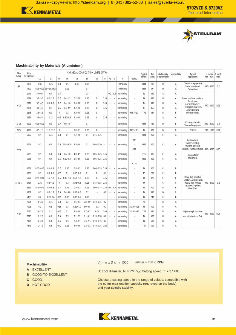
www.kennametal.com 91
Al1050 0.05 0.25 0.4 0.5 0.05 0.05 - - - - - H14 105 D A
600 - 3000 0,21100 0.05~0.20 Si+Fe1.0max 0.05 - 0.1 - - - - - H14 90 D A
Al-Cu
2011 50.~60. 0.4 0.7 - - 0.3 - - 0.2 0.6 - T3 310 A A
400 - 2500 0,25
2014 3.9~5.0 0.5~1.2 0.7 0.4~1.2 0.2~0.8 0.25 0.1 0.15 - - - T6 430 B A
2017 3.5~4.5 0.2~0.8 0.7 0.4~1.0 0.4~0.8 0.25 0.1 0.15 - - - T4 390 B A
2024 3.8~4.9 0.5 0.5 0.3~0.9 1.2~1.8 0.25 0.1 0.15 - - - T4 465 B A
2218 3.5~4.5 0.9 1 0.2 1.2~1.8 0.25 0.1 - - - Ni1.7~2.3 T72 331 B B
2224 3.8~4.4 0.12 0.15 0.30~0.9 1.2~1.8 0.25 0.1 0.15 - - - A A
Al-Mn 3003 0.05~0.20 0.6 0.7 1.0~1.5 - 0.1 - - - - - H14 140 D B 200 - 2500 0,2
Al-Si 4032 0.5~1.3 11.0~13.5 1 - 0.8~1.3 0.25 0.1 - - - Ni0.5~1.3 T6 379 B D 200 - 1000 0,18
Al-Mg
5052 0.1 0.25 0.4 0.1 2.2~2.8 0.1 0.15~0.35 - - - - H14 260 C A
400 - 3000 0,25
H34
5056 0.1 0.3 0.4 0.05~0.20 4.5~5.6 0.1 0.05~0.20 - - - - H12 300 C A
H32
5083 0.1 0.4 0.4 0.4~1.0 4.0~4.9 0.25 0.05~0.25 0.15 - - - H112 335 C A
5086 0.1 0.4 0.5 0.20~0.7 3.5~4.5 0.25 0.05~0.25 0.15 - - - H32 300 C A
H116
Al-Mg-Si
6061 0.15~0.40 0.4~0.8 0.7 0.15 0.8~1.2 0.25 0.04~0.35 0.15 - - - T6 300 C B
400 - 2500 0,2
6063 0.1 0.2~0.6 0.35 0.1 0.45~0.9 0.1 0.1 0.1 - - - T5 200 C B
6070 0.15~0.40 1.0~1.7 0.5 0.40~1.0 0.50~1.2 0.25 0.1 0.15 - - - T6 379 C C
6151 0.35 0.6~1.2 1 0.2 0.45~0.8 0.25 0.15~0.35 0.15 - - - T6 C C
6262 0.15~0.40 0.4~0.8 0.7 0.15 0.8~1.2 0.25 0.04~0.14 0.15 0.4 0.7 - T9 400 B B
6351 0.1 0.7~1.3 0.5 0.4~0.8 0.40~0.8 0.2 - 0.2 - - - T6 310 D C
6463 0.2 0.20~0.6 0.15 0.05 0.45~0.9 0.05 - - - - - T6 241 C B
Al-Zn
7001 1.6~2.6 0.35 0.4 0.2 2.6~3.4 6.8~8.0 0.18~0.35 0.2 - - - O B A
400 - 3000 0,25
7003 0.2 0.3 0.35 0.3 0.50~1.0 5.0~6.5 0.2 0.2 - - Zr0.05~0.25 T5 400 B A
7050 2.0~2.6 0.12 0.15 0.1 1.9~2.6 5.7~6.7 0.04 0.06 - - Zr0.08~0.15 T73 530 B A
7075 1.2~2.0 0.4 0.5 0.3 2.1~2.9 5.1~6.1 0.18~0.28 0.2 - - - T6 570 B A
7178 1.6~2.4 0.4 0.5 0.3 2.4~3.1 6.3~7.3 0.18~0.35 0.2 - - - T6 600 B A
7475 1.2~1.9 0.1 0.12 0.06 1.9~2.6 5.2~6.2 0.18~0.25 0.06 - - - T61 565 B A
Machinability by Materials (Aluminium)
99.50min Chemical equipment Sheet metal work
Coiled tube99.00min
remaining
Screw machine products. Tuck frame.
Aircraft structure. Jet engine impellers.
Aircraft engine cylinder heads.
remaining
remaining
remaining
remaining
remaining
remaining Cooking utensils. Chemical equipment.
remaining Pistons.
remaining
Architectural. Cable Sheeting. Welded pressure
vessels. Hydraulic tubes.
remaining
remaining Transportation equipment.remaining
remaining
Heavy duty structure.Furniture. Architectural.
Heavy duty weldedstructure. Pipeline.
Heat Sink.
remaining
remaining
remaining
remaining
remaining
remaining
remaining
remaining
remaining High strength structure.
remaining Aircraft structure. Bat.
remaining
remaining
Alloy Group
Alloy Designation
CHEMICAL COMPOSITION LIMITS (WT%) Typical tremper
Rm (Mpa)
Machinability Chip formation
Machinability Typical Applications
vc m/min min. - max.
fz mm/Z max.
Cu Si Fe Mn Mg Zn Cr Ti Pb Bi Al Others
MachinabilityA EXCELLENTB GOOD-TO-EXCELLENTC GOODD NOT GOOD
D: Tool diameter, N: RPM, Vc: Cutting speed, π = 3.1416
Choose a cutting speed in the range of values, compatible with the cutter max rotation capacity (engraved on the body) and your spindle stability.
Vc = π x D x n / 1000 m/min = mm x RPM
5702VZD & 5720VZTechnical Information
KMST-009_ExpFocusBroMetricUK_48-IBC.indd 91 4/25/14 4:38 PM
Заказ инструмента: http://steelcam.org | 8 (343) 382-52-03 | [email protected]

www.kennametal.com92
M6 10
M8 30
M10 50
M12 80
M16 110
M6 13 10
M8 16 30
M10 22 50
M12 27 80
M16 32 110
M20 40 120
Thread sizes (mm)
Cutter BoreSize (mm)
Torque ValuesNm
Thread sizes(mm)
Torque ValuesNm
The Cutter Nomenclature Code:
Tighten the Modular Head to the Extension, with lubricant, apply the torque value of:
Tighten the bolt between the shell mill and tool holder, with lubricant apply the torque value of:
Cylindrical shanks & HSK shanks (special): 5702VZD14 and 5720VZ16 are designed and balanced to G6.3 at 30,000 rpm for diameters 50mm and below. Diameters larger then 50mm are balanced to G6.3 at 24,000 rpm. Cylindrical shank tools mounted in a shrink fit holder or any other mill chuck holder + inserts + screws must be re-inspected for balance by the end user when exceeding 8,000 rpm. End user must balance the assembly to a G6.3 value minimum.
Shell Mills and Modular Heads: 5720VZ16 Shell Mills and Modular Heads are not balanced. These tools must be re-inspected for balance as an assembly, cutter + adapter + inserts + screws by the end user when at or exceeding 8,000 rpm. End user must balance the assembly to a G6.3 value minimum.
Balancing requires removing some material by drilling or milling operations. To avoid making modular heads weaker, limit these operations by avoiding high rpm.
For each new modular head added to the same extension, re-balance the assembly. For each new Shell Mill installed on the same toolholder, re-balance the assembly.
5702 = Stellram Product Family V = Screw fixation Z = Insert shape (parallelogram) D = ISO insert clearance (D = 15°) 14 = Insert edge length (mm) C = Plain straight shank (No flats) A = Through the tool coolant 020 = Cutting diameter (mm) R = Right hand tool 58 = Reach of tool in mm -2 = Maximum value of the insert radius in 1/10mm increments
This tool must only be used for the following applications: Face milling, shoulder milling, slotting and pocketing.
Example: 5702VZD14CA020R58-2
Recommendations for High Speed Machiningat 8,000 rpm or above.
• Check spindle condition: Runout Balancing Clamping of the attachment in traction Marking and cleanliness
• Check that the tool is suitable for the required use.
• Inserts must be locked positively in the pocket and secured using the torx screw provided. The screw must be torqued to the correct value as indicated in our charts on the steel product page 88. For security use a new screw each time.
• Check the balancing of the – assembled tool – cutter body, inserts and attachment.
• Before start up, note the maximum RPM engraved on the tool or in our technical documents. The maximum RPM is linked to a precise balancing value.
• Ensure that the field of application of the tool shown in our technical documents and technological parameters is observed: ae (mm) width of cut, lateral engagement (radial) ap (mm) Axial depth of cut fz (mm/tooth) Feed per tooth n (rpm) RPM
Stellram cannot accept responsibility for misuse of this product: • Non observance of the above instructions • Machine without casing • Incorrect clamping of workpieces • No safety device on the machine • Any misuse or incorrect clamping
The optimum rotation must be determined by condition of the spindle. The spindle must be rigid to run at these higher RPMs.
Under no circumstances must any attempt be made to repair this tool. The only permitted maintenance is the indexing or replacement of the inserts. Use a new screw for each insert replacement.
When assembling the cutter to a shrink fit holder, the maximum protrusion can not exceed 10% of the reach of tool.
5702VZD & 5720VZTechnical Information
KMST-009_ExpFocusBroMetricUK_48-IBC.indd 92 4/25/14 4:38 PM
Заказ инструмента: http://steelcam.org | 8 (343) 382-52-03 | [email protected]

www.kennametal.com93
Metalcutting SafetyIMPORTANT SAFETY INSTRUCTIONS Read before using the tools in this catalog!Projectile and Fragmentation Hazards:
Modern metalcutting operations involve high spindle and cutter speeds and high temperatures and cutting forces. Hot metal chips may fly off the workpiece during metalcutting. Although cutting tools are designed and manufactured to withstand high cutting forces and temperatures, they can sometimes fragment, particularly if they are subjected to over-stress, severe impact, or other abuse.
To avoid injury: • Always wear appropriate personal protective equipment, including safety goggles, when operating metalcutting machines or working nearby. • Always make sure all machine guards are in place.
Breathing and Skin Contact Hazards:Grinding carbide or other advanced cutting tool materials produces dust or mist containing metallic particles. Breathing this dust or mist — especially over an extended period — can cause temporary or permanent lung disease or make existing medical conditions worse. Contact with this dust or mist can irritate eyes, skin, and mucous membranes and may make existing skin conditions worse.
To avoid injury: • Always wear breathing protection and safety goggles when grinding. • Provide ventilation control and collect and properly dispose of dust, mist, or sludge from grinding. • Avoid skin contact with dust or mist.
For more information, read the applicable Material Safety Data Sheet provided by Kennametal and consult General Industry Safety and Health Regulations, Part 1910, Title 29 of the Code of Federal Regulations.
These safety instructions are general guidelines. Many variables affect machining operations. It is impossible to cover every specific situation. The technical information included in this catalog and recommendations on machining practices may not apply to your particular operation. For more information, consult Kennametal’s Metalcutting Safety booklet, available free from Kennametal at 724.539.5747 or fax 724.539.5439. For specific product safety and environmental questions, contact our Corporate Environmental Health and Safety Office at 724.539.5066 or fax 724.539.5372.
Kennametal, the stylized K, Stellram and X Grades are trademarks of Kennametal, Inc. and are used as such herein. The absence of a product, service name, or logo from this list does not constitute a waiver of Kennametal’s trademark or other intellectual property rights concerning that name or logo. ©Copyright 2014 by Kennametal Inc., Latrobe, PA 15650. All rights reserved.
KMST-009_ExpFocusBroMetricUK_48-IBC.indd 93 4/25/14 4:38 PM
Заказ инструмента: http://steelcam.org | 8 (343) 382-52-03 | [email protected]