steel placement handbook
TRANSCRIPT
Reinforcing Steel Placement Handbook
Produced by
NEITC Project Development Division Reinforcing Steel Placement Process Improvement Team
Reinforcement Steel Placement Process Improvement
Over the past several construction seasons, problems have become increasingly evident in the proper placement and maintainance of reinforcing steel in all phases of bridge and culvert construction. During the winter of 1998 and 1999, David Roeber, NEITC Construction Engineer, assembled a process improvement team to review these problems. Dave also directed the team to put together a handbook to assist not only structures inspectors, but contractor’s employees in understanding the reasoning behind the essential need for properly placing and maintaining reinforcing steel in bridges and culverts. The team was charged with completing their work prior to the 1999 construction. The team included the following NEITC and Bridge Design personnel:
Stanley Perkins, New Hampton RCE Office, Team Leader Bob Beckman, New Hampton RCE Office
Gene Pavelka, Britt RCE Office Mark Homan, Waterloo RCE Office
Clyde Mohorne, Waterloo RCE Office Gregg Durbin, Office of Bridge Design
Dusty Rolando, Britt RCE Office
Dick Peterson, Facilitator
The team met weekly from late February through March. Following a brief “working in teams” training session during the first meeting, dug into their team’s assignment. The NEITC Reinforcing Steel Placement Process Improvement Team recommends adoption of this handbook to increase awareness of the importance of, and to ensure proper placement and maintenance of reinforcing steel prior to, during, and following placement of structural concrete.

In the pages that follow, you will find technical information on reinforcing steel placement and spacing, which the team found most enlightening. The team feels this explains, in ordinary terms, why proper placement and maintaining that placement is so important and critical to the structure’s strength and durability. The team developed reinforcing steel checklists for all phases of structure’s construction. The checklists also include Specification and Construction Manual references in a single location for your convenience. The team encourages inspectors to read and understand the explanations on the critical placement of reinforcing steel and to use the checklists, on the work site, as reminders to review those most critical items, perhaps several times, which have recently and repeatedly been recognized as problems. The team has assembled and reviewed the checklists and references. As each and all of you use this handbook, the team asks that you contact any team member if you find the handbook helpful, or not helpful, as you work through the coming construction season. The team needs your comments to assist in evaluating the effectiveness of the handbook.
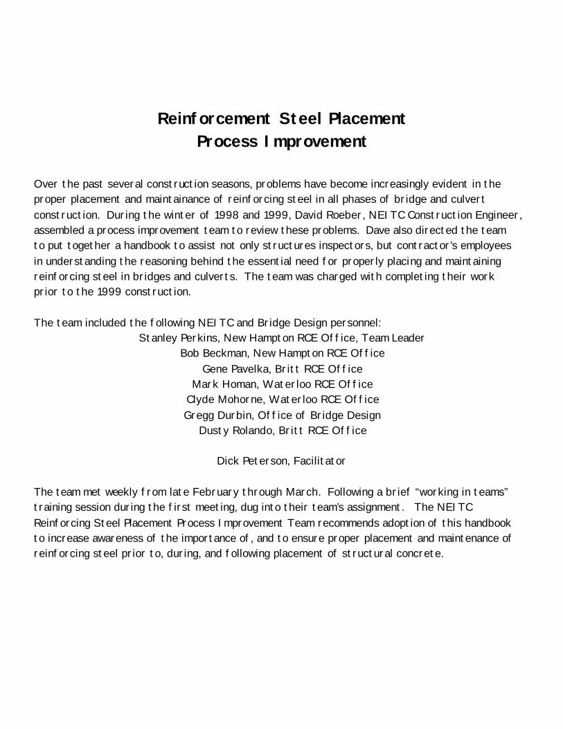
Template used in a pier footing to assure proper spacing & alignment of column steel.
Proper spacing of vertical column bars.
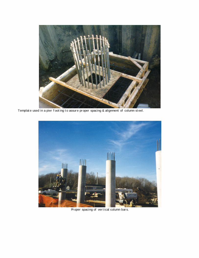
Hoop bars in pier diaphragm are properly and adequately supported.
Vertical bars in a culvert wall are properly and adequately supported.
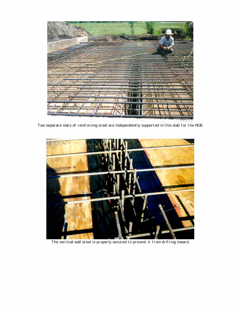
Two separate mats of reinforcing steel are independently supported in this slab for the RCB.
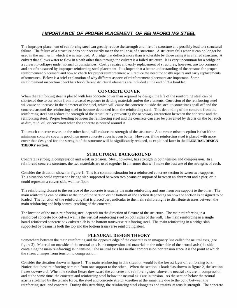
The vertical wall steel is properly secured to prevent it from drifting inward.
IMPORTANCE OF PROPER PLACEMENT OF REINFORCING STEEL
The improper placement of reinforcing steel can greatly reduce the strength and life of a structure and possibly lead to a structural failure. The failure of a structure does not necessarily mean the collapse of a structure. A structure fails when it can no longer be used in the manner in which it was intended. A bridge that deflects more than is tolerable by those using it is a failed structure. A culvert that allows water to flow in a path other than through the culvert is a failed structure. It is very uncommon for a bridge or a culvert to collapse under normal circumstances. Costly repairs and early replacement of structures, however, are too common and are often caused by improper reinforcing steel placement. It is hoped that a better understanding of the reasons for proper reinforcement placement and how to check for proper reinforcement will reduce the need for costly repairs and early replacements of structures. Below is a brief explanation of why different aspects of reinforcement placement are important. Some reinforcement inspection checklists for different structural elements are included at the end of this booklet.
CONCRETE COVER When the reinforcing steel is placed with less concrete cover than required by design, the life of the reinforcing steel can be shortened due to corrosion from increased exposure to deicing materials and/or the elements. Corrosion of the reinforcing steel will cause an increase in the diameter of the steel, which will cause the concrete outside the steel to sometimes spall off and the concrete around the reinforcing steel to become debonded from the reinforcing steel. This debonding of the concrete from the reinforcing steel can reduce the strength of the structure by preventing the necessary interaction between the concrete and the reinforcing steel. Proper bonding between the reinforcing steel and the concrete can also be prevented by debris on the bar such as dirt, mud, oil, or corrosion when the concrete is poured around it. Too much concrete cover, on the other hand, will reduce the strength of the structure. A common misconception is that if the minimum concrete cover is good then more concrete cover is even better. However, if the reinforcing steel is placed with more cover than designed for, the strength of the structure will be significantly reduced, as explained later in the FLEXURAL DESIGN THEORY section.
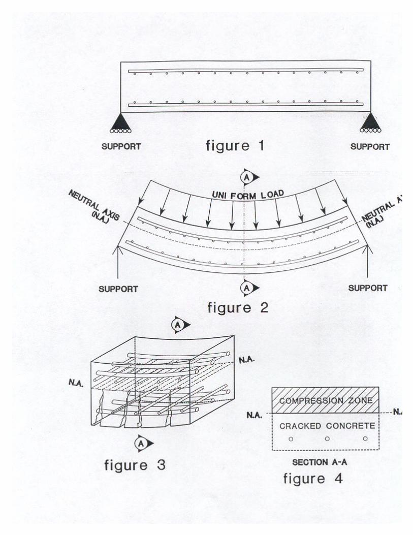
STRUCTURAL BACKGROUND Concrete is strong in compression and weak in tension. Steel, however, has strength in both tension and compression. In a reinforced concrete structure, the two materials are used together in a manner that will make the best use of the strengths of each. Consider the situation shown in figure 1. This is a common situation for a reinforced concrete section between two supports. This situation could represent a bridge slab supported between two beams or supported between an abutment and a pier, or it could represent a culvert slab, wall, or floor. The reinforcing closest to the surface of the concrete is usually the main reinforcing and runs from one support to the other. The main reinforcing can be either at the top of the section or the bottom of the section depending on how the section is designed to be loaded. The function of the reinforcing that is placed perpendicular to the main reinforcing is to distribute stresses between the main reinforcing and help control cracking of the concrete. The location of the main reinforcing steel depends on the direction of flexure of the structure. The main reinforcing in a reinforced concrete box culvert wall is the vertical reinforcing steel on both sides of the wall. The main reinforcing in a single barrel reinforced concrete box culvert slab is the bottom transverse reinforcing steel. The main reinforcing in a bridge slab supported by beams is both the top and the bottom transverse reinforcing steel.
FLEXURAL DESIGN THEORY Somewhere between the main reinforcing and the opposite edge of the concrete is an imaginary line called the neutral axis, (see figure 2). Material on one side of the neutral axis is in compression and material on the other side of the neutral axis (the side containing the main reinforcing) is in tension. The neutral axis has neither compression nor tension since it is the point at which the stress changes from tension to compression. Consider the situation shown in figure 1. The main reinforcing in this situation would be the lowest layer of reinforcing bars. Notice that these reinforcing bars run from one support to the other. When the section is loaded as shown in figure 2, the section flexes downward. When the section flexes downward the concrete and reinforcing steel above the neutral axis are in compression and at the same time, the concrete and reinforcing steel below the neutral axis are in tension. As the section below the neutral axis is stretched by the tensile force, the steel and concrete stretch together at the same rate due to the bond between the reinforcing steel and concrete. During this stretching, the reinforcing steel elongates and retains its tensile strength. The concrete
in the tension zone however, cracks and contributes no tensile strength to the structure (see figure 3). Therefore, the concrete below the neutral axis is disregarded when determining the flexural strength of the structure. The theoretical design section shown in figure 4 is a cross section of the structure looking along the main reinforcing showing only the materials considered to be contributing to the strength of the structure. The dashed lines in figure 4 represent the area of cracked concrete that does not contribute to the strength of the structure. The steel in the compression zone does not significantly increase the compressive strength of the concrete and therefore the area above the neutral axis is assumed to be solid concrete for design purposes. Placing the reinforcing steel with more than the design cover causes the neutral axis to be shifted higher in the section, which reduces the area of concrete that is in compression and increases the cracked area of concrete in tension. This decrease in useful concrete and increase in useless concrete greatly reduces the strength of the structure.
LAP LENGTH The design lap length is usually a minimum length required to transfer stress from one bar to another. Consider for example, the longitudinal steel in the slab of a bridge or in a culvert, or the vertical steel in the back face of a culvert wall. It would be ideal to make these bars one continuous bar, this however would be impractical due to difficulties in transporting and handling the steel. In order to achieve the same effect as having one continuous bar, the design will call for shorter bars and minimum lap lengths. If the actual lap length is less than the required lap length, the stress may not be transferred to the other bar, which could cause a failure in the structure at that lap location.
DEVELOPMENT LENGTH
The development length is often shown on the plans as a minimum embedment length. The purpose of the development length is to anchor the reinforcing bars beyond the area where the strength of the bars is needed. Without the required development length, the reinforcing bar would pull out of the concrete surrounding it and the structure could fail. A typical example of this situation would be the top transverse reinforcing bars in the cantilevered section of a bridge slab outside the exterior beam of a bridge. The critical section of the slab is just outside the outside edge of the beam supporting the slab. The reinforcing bars must extend into the slab beyond the critical section for a required length. If the reinforcing bars do not extend beyond the critical section sufficiently, they will be pulled out and the structure will fail.
BAR SPACING AND BAR SIZE The amount of reinforcing steel in the tension area of the structure also has a large impact on the strength of the structure. Both the spacing and the size of the reinforcing bars control the amount of steel in the tension area. The impacts to flexural strength from deviations in bar spacing and bar size are shown in figure 5.
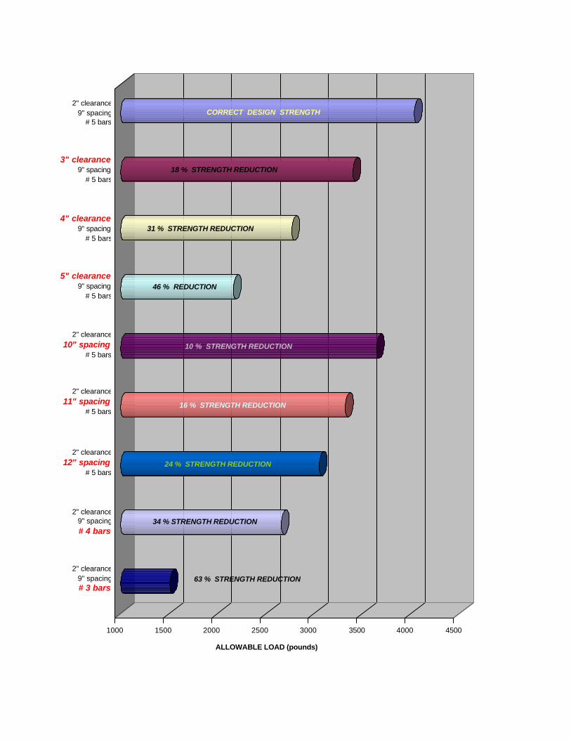
1000 1500 2000 2500 3000 3500 4000 4500
ALLOWABLE LOAD (pounds)
CORRECT DESIGN STRENGTH
16 % STRENGTH REDUCTION
31 % STRENGTH REDUCTION
46 % REDUCTION
10 % STRENGTH REDUCTION
18 % STRENGTH REDUCTION
24 % STRENGTH REDUCTION
34 % STRENGTH REDUCTION
63 % STRENGTH REDUCTION
2" clearance9" spacing
# 5 bars
3" clearance9" spacing
# 5 bars
4" clearance9" spacing
# 5 bars
5" clearance9" spacing
# 5 bars
2" clearance10" spacing
# 5 bars
2" clearance11" spacing
# 5 bars
2" clearance12" spacing
# 5 bars
2" clearance9" spacing# 4 bars
2" clearance9" spacing# 3 bars
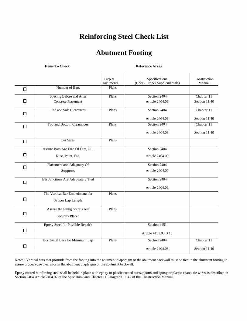
Reinforcing Steel Check List
Abutment Footing
Items To Check Reference Areas Project
Documents Specifications
(Check Proper Supplementals) Construction
Manual Number of Bars
Plans
Spacing Before and After Plans Section 2404 Chapter 11 Concrete Placement
Article 2404.06 Section 11.40
End and Side Clearances
Plans Section 2404 Chapter 11
Article 2404.06 Section 11.40
Top and Bottom Clearances
Plans Section 2404 Chapter 11
Article 2404.06 Section 11.40
Bar Sizes
Plans
Assure Bars Are Free Of Dirt, Oil, Section 2404
Rust, Paint, Etc.
Article 2404.03
Placement and Adequacy Of Section 2404
Supports
Article 2404.07
Bar Junctions Are Adequately Tied
Section 2404
Article 2404.06
The Vertical Bar Embedments for Plans
Proper Lap Length
Assure the Piling Spirals Are Plans
Securely Placed
Epoxy Steel for Possible Repair's
Section 4151
Article 4151.03 B 10
Horizontal Bars for Minimum Lap
Plans Section 2404 Chapter 11
Article 2404.08 Section 11.40
Notes : Vertical bars that protrude from the footing into the abutment diaphragm or the abutment backwall must be tied in the abutment footing to insure proper edge clearance in the abutment diaphragm or the abutment backwall. Epoxy coated reinforcing steel shall be held in place with epoxy or plastic coated bar supports and epoxy or plastic coated tie wires as described in Section 2404 Article 2404.07 of the Spec Book and Chapter 11 Paragraph 11.42 of the Construction Manual.
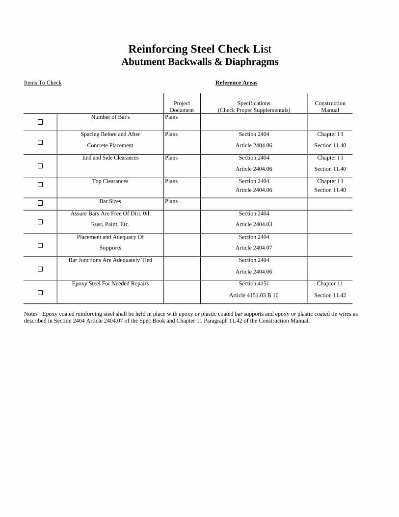
Reinforcing Steel Check List Abutment Backwalls & Diaphragms
Items To Check Reference Areas
Project Document
Specifications (Check Proper Supplementals)
Construction Manual
Number of Bar's Plans
Spacing Before and After Plans Section 2404 Chapter I I
Concrete Placement Article 2404.06 Section 11.40
End and Side Clearances Plans Section 2404 Chapter I I
Article 2404.06 Section 11.40
Top Clearances Plans Section 2404 Chapter I I Article 2404.06 Section 11.40
Bar Sizes Plans
Assure Bars Are Free Of Dirt, 0il, Section 2404
Rust, Paint, Etc. Article 2404.03
Placement and Adequacy Of Section 2404
Supports Article 2404.07
Bar Junctions Are Adequately Tied Section 2404
Article 2404.06
Epoxy Steel For Needed Repairs Section 4151 Chapter 11
Article 4151.03 B 10 Section 11.42
Notes : Epoxy coated reinforcing steel shall be held in place with epoxy or plastic coated bar supports and epoxy or plastic coated tie wires as described in Section 2404 Article 2404.07 of the Spec Book and Chapter 11 Paragraph 11.42 of the Construction Manual.
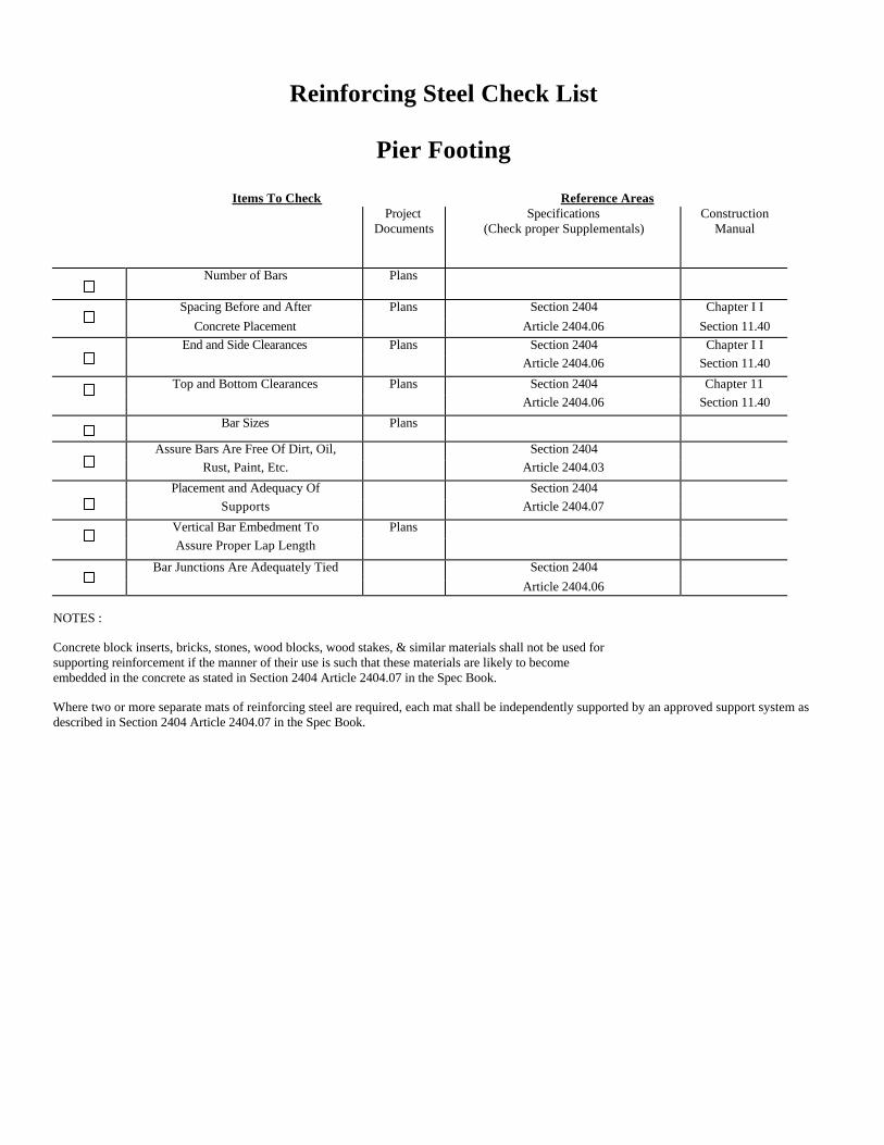
Reinforcing Steel Check List
Pier Footing
Items To Check Reference Areas Project
Documents Specifications
(Check proper Supplementals) Construction
Manual
Number of Bars
Plans
Spacing Before and After Plans Section 2404 Chapter I I Concrete Placement Article 2404.06 Section 11.40 End and Side Clearances Plans Section 2404 Chapter I I Article 2404.06 Section 11.40
Top and Bottom Clearances Plans Section 2404 Chapter 11 Article 2404.06 Section 11.40
Bar Sizes Plans
Assure Bars Are Free Of Dirt, Oil, Section 2404 Rust, Paint, Etc. Article 2404.03
Placement and Adequacy Of Section 2404 Supports Article 2404.07
Vertical Bar Embedment To Plans Assure Proper Lap Length
Bar Junctions Are Adequately Tied Section 2404 Article 2404.06 NOTES : Concrete block inserts, bricks, stones, wood blocks, wood stakes, & similar materials shall not be used for supporting reinforcement if the manner of their use is such that these materials are likely to become embedded in the concrete as stated in Section 2404 Article 2404.07 in the Spec Book. Where two or more separate mats of reinforcing steel are required, each mat shall be independently supported by an approved support system as described in Section 2404 Article 2404.07 in the Spec Book.
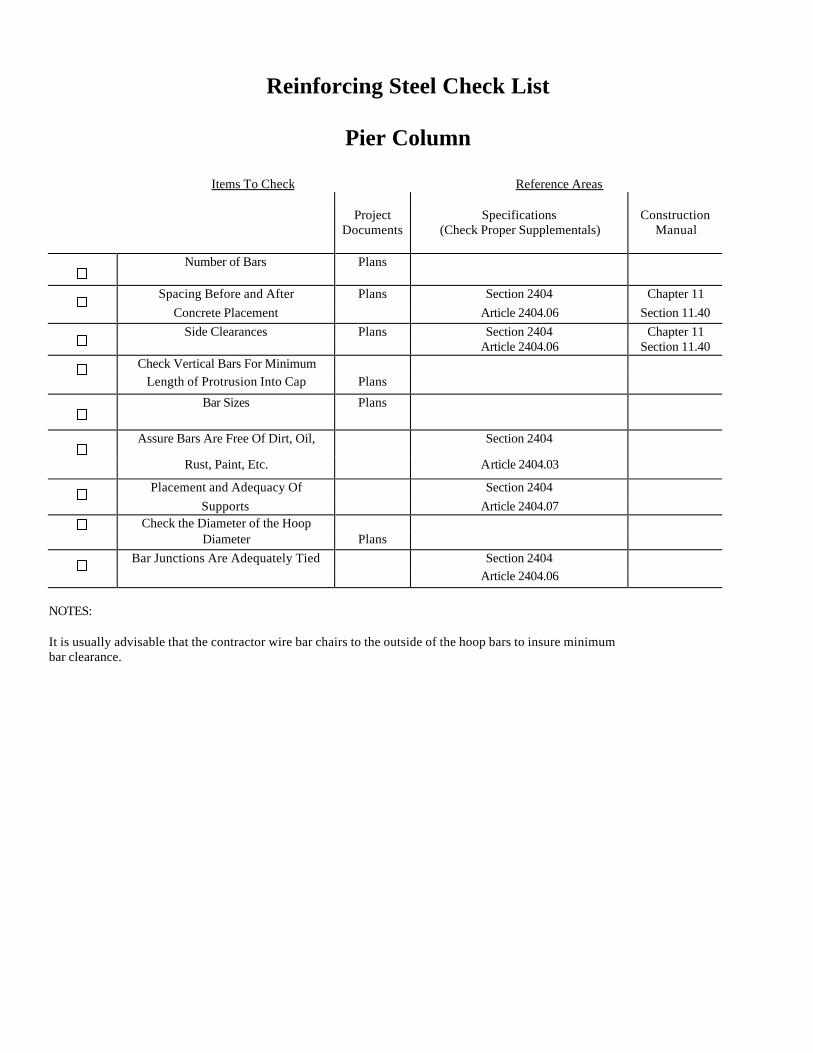
Reinforcing Steel Check List
Pier Column
Items To Check Reference Areas Project
Documents Specifications
(Check Proper Supplementals)
Construction Manual
Number of Bars
Plans
Spacing Before and After Plans Section 2404 Chapter 11 Concrete Placement Article 2404.06 Section 11.40 Side Clearances Plans Section 2404 Chapter 11 Article 2404.06 Section 11.40 Check Vertical Bars For Minimum Length of Protrusion Into Cap Plans
Bar Sizes Plans
Assure Bars Are Free Of Dirt, Oil, Section 2404
Rust, Paint, Etc. Article 2404.03
Placement and Adequacy Of Section 2404 Supports Article 2404.07 Check the Diameter of the Hoop Diameter Plans
Bar Junctions Are Adequately Tied Section 2404 Article 2404.06
NOTES: It is usually advisable that the contractor wire bar chairs to the outside of the hoop bars to insure minimum bar clearance.
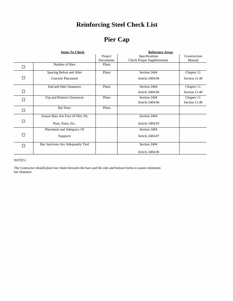
Reinforcing Steel Check List
Pier Cap
Items To Check Reference Areas Project Specifications Construction Documents Check Proper Supplementals Manual Number of Bars
Plans
Spacing Before and After Plans Section 2404 Chapter 11
Concrete Placement
Article 2404.06 Section 11.40
End and Side Clearances Plans Section 2404 Chapter 11
Article 2404.06 Section 11.40
Top and Bottom Clearances Plans Section 2404 Chapter 11 Article 2404.06 Section 11.40
Bar Sizes
Plans
Assure Bars Are Free Of Dirt, 0il, Section 2404
Rust, Paint, Etc. Article 2404.03
Placement and Adequacy Of Section 2404
Supports
Article 2404.07
Bar Junctions Are Adequately Tied
Section 2404
Article 2404.06 NOTES : The Contractor should place bar chairs between the bars and the side and bottom forms to assure minimum bar clearance.
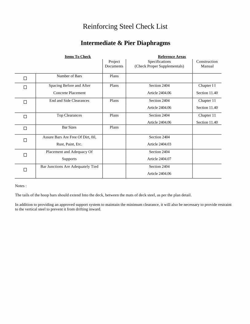
Reinforcing Steel Check List
Intermediate & Pier Diaphragms
Items To Check Reference Areas Project
Documents Specifications
(Check Proper Supplementals) Construction
Manual Number of Bars
Plans
Spacing Before and After Plans Section 2404 Chapter I I
Concrete Placement Article 2404.06 Section 11.40
End and Side Clearances Plans Section 2404 Chapter 11
Article 2404.06 Section 11.40
Top Clearances Plans Section 2404 Chapter 11
Article 2404.06 Section 11.40 Bar Sizes
Plans
Assure Bars Are Free Of Dirt, 0il, Section 2404
Rust, Paint, Etc. Article 2404.03
Placement and Adequacy Of Section 2404
Supports Article 2404.07
Bar Junctions Are Adequately Tied Section 2404
Article 2404.06
Notes : The tails of the hoop bars should extend Into the deck, between the mats of deck steel, as per the plan detail. In addition to providing an approved support system to maintain the minimum clearance, it will also be necessary to provide restraint to the vertical steel to prevent it from drifting inward.
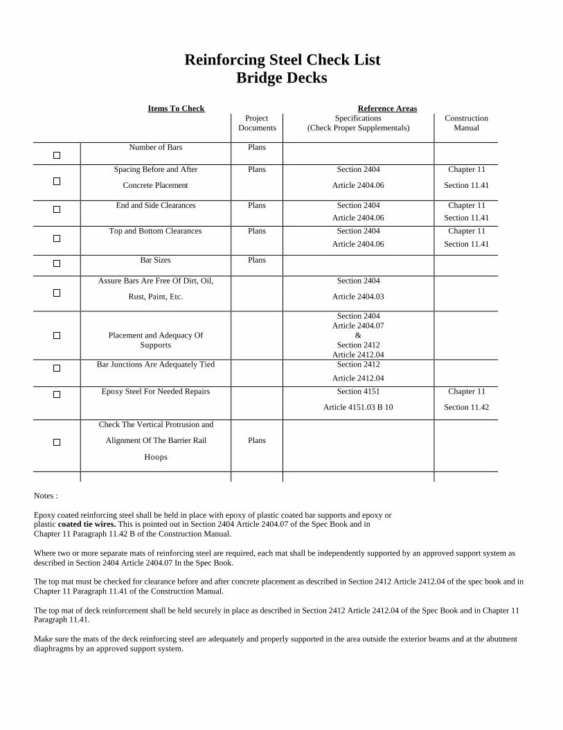
Reinforcing Steel Check List Bridge Decks
Items To Check Reference Areas
Project Documents
Specifications (Check Proper Supplementals)
Construction Manual
Number of Bars
Plans
Spacing Before and After Plans Section 2404 Chapter 11
Concrete Placement
Article 2404.06 Section 11.41
End and Side Clearances Plans Section 2404 Chapter 11 Article 2404.06 Section 11.41
Top and Bottom Clearances Plans Section 2404 Chapter 11
Article 2404.06 Section 11.41
Bar Sizes Plans
Assure Bars Are Free Of Dirt, Oil, Section 2404
Rust, Paint, Etc.
Article 2404.03
Section 2404 Article 2404.07 Placement and Adequacy Of & Supports Section 2412 Article 2412.04 Bar Junctions Are Adequately Tied Section 2412
Article 2412.04
Epoxy Steel For Needed Repairs Section 4151 Chapter 11
Article 4151.03 B 10 Section 11.42
Check The Vertical Protrusion and
Alignment Of The Barrier Rail Plans
Hoops
Notes : Epoxy coated reinforcing steel shall be held in place with epoxy of plastic coated bar supports and epoxy or plastic coated tie wires. This is pointed out in Section 2404 Article 2404.07 of the Spec Book and in Chapter 11 Paragraph 11.42 B of the Construction Manual. Where two or more separate mats of reinforcing steel are required, each mat shall be independently supported by an approved support system as described in Section 2404 Article 2404.07 In the Spec Book. The top mat must be checked for clearance before and after concrete placement as described in Section 2412 Article 2412.04 of the spec book and in Chapter 11 Paragraph 11.41 of the Construction Manual. The top mat of deck reinforcement shall be held securely in place as described in Section 2412 Article 2412.04 of the Spec Book and in Chapter 11 Paragraph 11.41. Make sure the mats of the deck reinforcing steel are adequately and properly supported in the area outside the exterior beams and at the abutment diaphragms by an approved support system.
Reinforcing Steel Check List
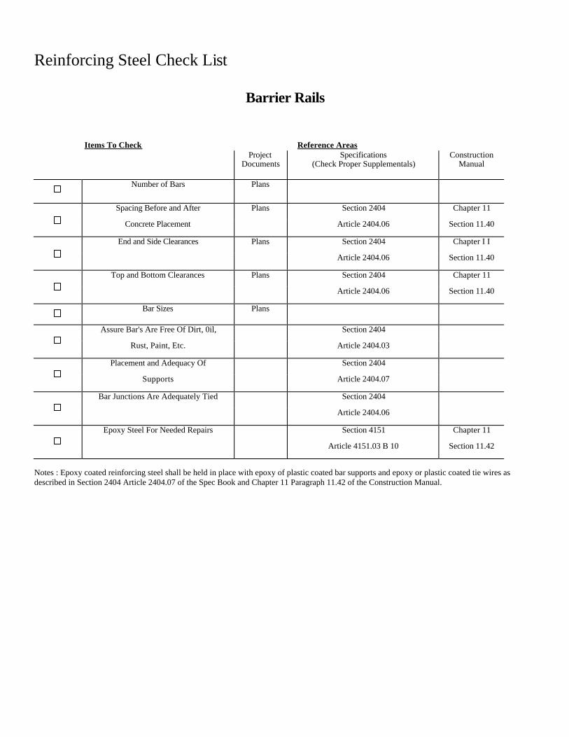
Barrier Rails
Items To Check Reference Areas Project
Documents Specifications
(Check Proper Supplementals) Construction
Manual Number of Bars Plans
Spacing Before and After Plans Section 2404 Chapter 11
Concrete Placement Article 2404.06 Section 11.40
End and Side Clearances Plans Section 2404 Chapter I I
Article 2404.06 Section 11.40
Top and Bottom Clearances Plans Section 2404 Chapter 11
Article 2404.06 Section 11.40
Bar Sizes Plans
Assure Bar's Are Free Of Dirt, 0il, Section 2404
Rust, Paint, Etc. Article 2404.03
Placement and Adequacy Of Section 2404
Supports Article 2404.07
Bar Junctions Are Adequately Tied Section 2404
Article 2404.06
Epoxy Steel For Needed Repairs Section 4151 Chapter 11
Article 4151.03 B 10 Section 11.42
Notes : Epoxy coated reinforcing steel shall be held in place with epoxy of plastic coated bar supports and epoxy or plastic coated tie wires as described in Section 2404 Article 2404.07 of the Spec Book and Chapter 11 Paragraph 11.42 of the Construction Manual.
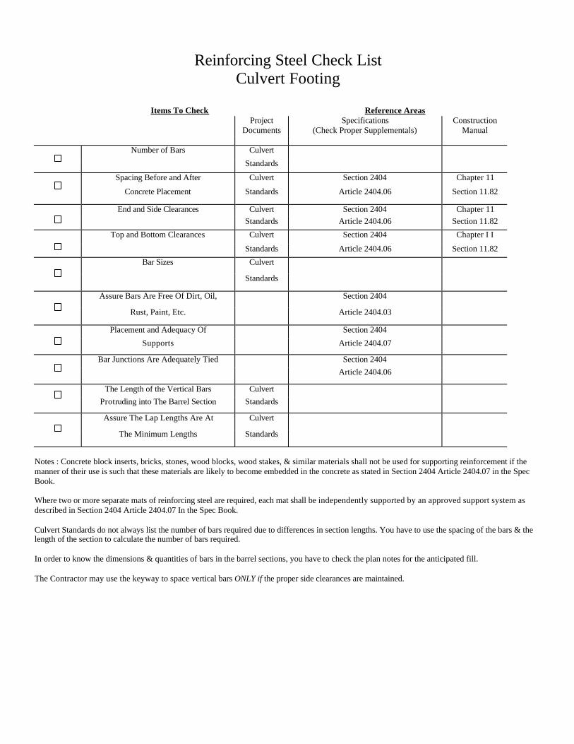
Reinforcing Steel Check List Culvert Footing
Items To Check Reference Areas
Project Documents
Specifications (Check Proper Supplementals)
Construction Manual
Number of Bars Culvert
Standards
Spacing Before and After Culvert Section 2404 Chapter 11
Concrete Placement Standards Article 2404.06 Section 11.82
End and Side Clearances Culvert Section 2404 Chapter 11 Standards Article 2404.06 Section 11.82
Top and Bottom Clearances Culvert Section 2404 Chapter I I
Standards Article 2404.06 Section 11.82
Bar Sizes Culvert
Standards
Assure Bars Are Free Of Dirt, Oil, Section 2404
Rust, Paint, Etc. Article 2404.03
Placement and Adequacy Of Section 2404
Supports Article 2404.07
Bar Junctions Are Adequately Tied Section 2404 Article 2404.06
The Length of the Vertical Bars Culvert Protruding into The Barrel Section Standards
Assure The Lap Lengths Are At Culvert
The Minimum Lengths Standards
Notes : Concrete block inserts, bricks, stones, wood blocks, wood stakes, & similar materials shall not be used for supporting reinforcement if the manner of their use is such that these materials are likely to become embedded in the concrete as stated in Section 2404 Article 2404.07 in the Spec Book. Where two or more separate mats of reinforcing steel are required, each mat shall be independently supported by an approved support system as described in Section 2404 Article 2404.07 In the Spec Book. Culvert Standards do not always list the number of bars required due to differences in section lengths. You have to use the spacing of the bars & the length of the section to calculate the number of bars required. In order to know the dimensions & quantities of bars in the barrel sections, you have to check the plan notes for the anticipated fill. The Contractor may use the keyway to space vertical bars ONLY if the proper side clearances are maintained.
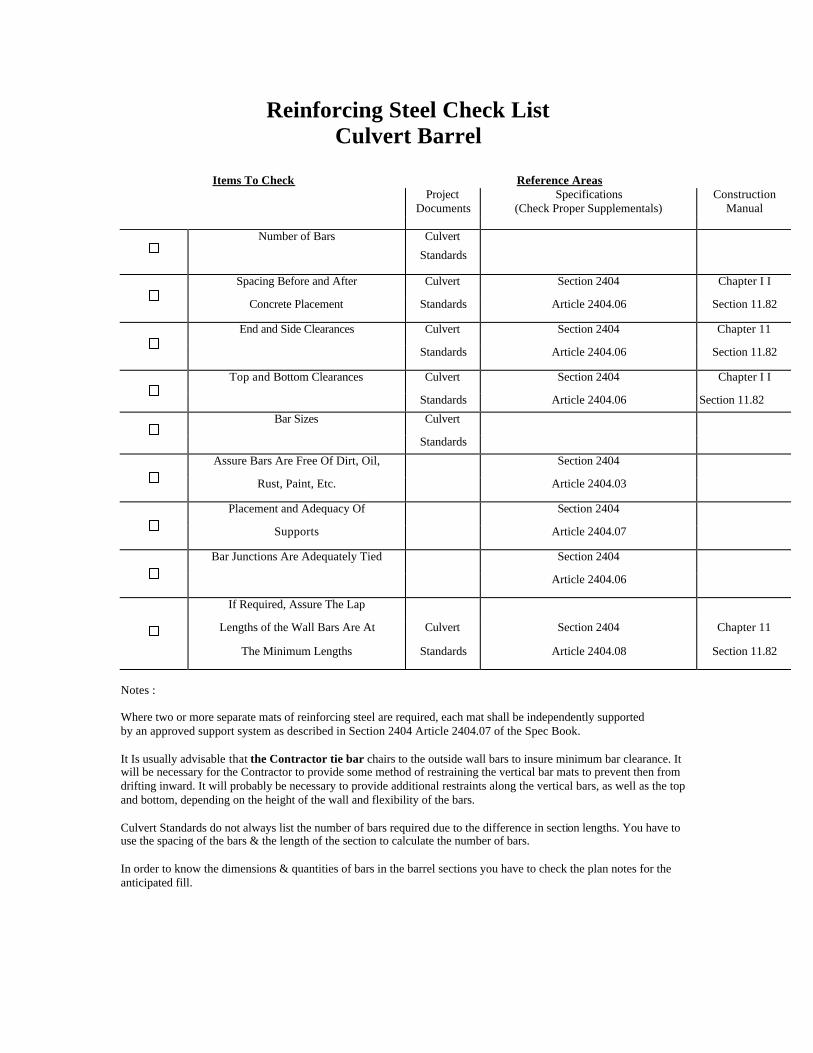
Reinforcing Steel Check List Culvert Barrel
Items To Check Reference Areas
Project Documents
Specifications (Check Proper Supplementals)
Construction Manual
Number of Bars Culvert
Standards
Spacing Before and After Culvert Section 2404 Chapter I I
Concrete Placement Standards Article 2404.06 Section 11.82
End and Side Clearances Culvert Section 2404 Chapter 11
Standards Article 2404.06 Section 11.82
Top and Bottom Clearances Culvert Section 2404 Chapter I I
Standards Article 2404.06 Section 11.82
Bar Sizes Culvert
Standards
Assure Bars Are Free Of Dirt, Oil, Section 2404
Rust, Paint, Etc. Article 2404.03
Placement and Adequacy Of Section 2404
Supports Article 2404.07
Bar Junctions Are Adequately Tied Section 2404
Article 2404.06
If Required, Assure The Lap
Lengths of the Wall Bars Are At Culvert Section 2404 Chapter 11
The Minimum Lengths Standards Article 2404.08 Section 11.82
Notes : Where two or more separate mats of reinforcing steel are required, each mat shall be independently supported by an approved support system as described in Section 2404 Article 2404.07 of the Spec Book. It Is usually advisable that the Contractor tie bar chairs to the outside wall bars to insure minimum bar clearance. It will be necessary for the Contractor to provide some method of restraining the vertical bar mats to prevent then from drifting inward. It will probably be necessary to provide additional restraints along the vertical bars, as well as the top and bottom, depending on the height of the wall and flexibility of the bars. Culvert Standards do not always list the number of bars required due to the difference in section lengths. You have to use the spacing of the bars & the length of the section to calculate the number of bars. In order to know the dimensions & quantities of bars in the barrel sections you have to check the plan notes for the anticipated fill.