steel connections software program cse: text of multimedia
TRANSCRIPT

CONNECTION STUDY ENVIRONMENT
CSE ONLINE LESSONS
TEXT
http://www.steelchecks.com
Via Pinturicchio, 24
20133 Milan - Italy
Copyright © 2000-2012 – Castalia s.r.l.
Rev.3 April, 6, 2012 – CSE Version 4.43

CSE: texts of the online movie lessons ©2001-2012 Castalia s.r.l. www.steelchecks.com [email protected]
Pagina vuota

CSE movie lessons may be freely downloaded here:
http://www.steelchecks.com/PRO/CS/lessons.asp
Note well: there could be some slight differences between the online movie lessons and the
text printed here, as the developping effort never stops and the program is continuously
upgraded. In case of difference, please look at the program guide, which is always updated to
the latest version of the program.
NOTE PER LA PRODUZIONE E LA STAMPA
- Prima di creare il pdf, fare una copia di questo documento ed eliminare eventuali lezioni mancanti (segnalate
con ###) Nome file: Steel-connections-lessons.pdf
- Non stampare i caratteri nascosti (strumenti-opzioni-stampa).
- Aggiornare data e numero dei prenodi dell’archivio nei filmati 006 e 008.
- Aggiornare revisione e versione in copertina.


CSE: texts of the online movie lessons ©2001-2012 Castalia s.r.l. www.steelchecks.com [email protected] 5
SUMMARY
001 OVERVIEW: The CSE Project ................................................................................... 11
006 OVERVIEW: Node library (last updated on ________ 20__ ) .................................. 15
007 OVERVIEW: Creating a node using the Light version ............................................... 16
008 OVERVIEW: Recording and reassigning a PRenode ................................................. 20
010 TOUR – Importing from the FEM – First steps .......................................................... 27
011 TOUR – Base plate ...................................................................................................... 30
012 TOUR – Flanged splice joint ....................................................................................... 34
013 TOUR – Flanged beam-column joint .......................................................................... 38
014 TOUR – Beam-beam joint with angle bracket ............................................................ 41
015 TOUR – Bracing node ................................................................................................. 44
019 TOUR – CSE as a stand-alone program ...................................................................... 46
020 TOUR – Beam-column joint (angle bracket)............................................................... 49
021 TOUR – Beam-beam joint (welded) ............................................................................ 51
022 TOUR – Splice joint (flanged) ..................................................................................... 53
030 TOUR – Non-typical joints .......................................................................................... 54
100 WORKFLOW STAGES: the FULL version vs the LIGHT version ........................... 57
101 FULL Stage 1a: importing the FEM model ................................................................. 60
102 FULL Stage 1b: manually creating or modifying the FEM model .............................. 62
103 FULL Stage 1c: automatically creating the FEM model ............................................. 63
105 FULL Stage 2: searching for members ........................................................................ 65
110 FULL Stage 3: searching for JNodes ........................................................................... 66
120 FULL Stage 4a: manually creating the Renode from scratch ...................................... 69
130 FULL Stage 4b: creating the Renode automatically or semi-automatically ................ 71
140 FULL Stage 5: setting up the checks ........................................................................... 73
145 FULL Stage 6: running the checks and analysing the results ...................................... 76
150 LIGHT Stage 1a: importing the model, searching for JNodes .................................... 78

CSE: texts of the online movie lessons ©2001-2012 Castalia s.r.l. www.steelchecks.com [email protected]
151 LIGHT Stage 1b: automatically creating the model for an individual node ................ 79
160 LIGHT Stage 2: constructing the Renode .................................................................... 80
165 LIGHT Stage 3: modifying the Renode constructed ................................................... 82
170 LIGHT Stage 4: setting up the checks ......................................................................... 83
180 LIGHT Stage 5: running the checks and analysing the results .................................... 84
200 TERMINOLOGY: Nodes, JNodes and Renodes......................................................... 85
201 TERMINOLOGY: Classification of JNodes ............................................................... 87
202 TERMINOLOGY: Joined members, joiners, force transferrers, and stiffeners .......... 88
203 TERMINOLOGY: Stiffeners vs force transferrers ...................................................... 89
204 TERMINOLOGY: Rigid or elastic attachments .......................................................... 90
205 TERMINOLOGY: Bearing support ............................................................................ 91
207 TERMINOLOGY: Predefined variable ....................................................................... 92
208 TERMINOLOGY: User variable ................................................................................. 93
209 TERMINOLOGY: User checks ................................................................................... 94
301 TOPICS: Modelling the objects in CSE ...................................................................... 97
302 TOPICS: Representing joiners in CSE ........................................................................ 99
303 TOPICS: Identifying objects in CSE ......................................................................... 100
304 TOPICS: Connection ................................................................................................. 102
305 TOPICS: Chains......................................................................................................... 105
306 TOPICS: Renode coherence ...................................................................................... 107
307 TOPICS: Overlaps ..................................................................................................... 108
308 TOPICS: Work processes .......................................................................................... 109
310 TOPICS: Bolt layouts ................................................................................................ 110
320 TOPICS: Weld layouts .............................................................................................. 112
330 TOPICS: Internal forces needed for checking ........................................................... 113
331 TOPICS: Dummy combinations, user combinations and FEM combinations .......... 115
333 TOPICS: Member net-sections checks ...................................................................... 117

CSE: texts of the online movie lessons ©2001-2012 Castalia s.r.l. www.steelchecks.com [email protected] 7
334 TOPICS: Simplified force-transferrers checks .......................................................... 118
335 TOPICS: User checks ................................................................................................ 119
336 TOPICS: Block-tear checks ....................................................................................... 120
350 TOPICS: Bolt-layout checks...................................................................................... 121
360 TOPICS: Weld-layout checks .................................................................................... 122
370 TOPICS: Displacement checks .................................................................................. 123
380 TOPICS: Standard checks.......................................................................................... 124
390 TOPICS: Connection codes in the FEM model ......................................................... 125
400 INTERFACE: Overview ............................................................................................ 127
401 INTERFACE: Views ................................................................................................. 129
402 INTERFACE: Buttons ............................................................................................... 131
500 MENU: Overview ...................................................................................................... 135
501 MENU: File ............................................................................................................... 138
502 MENU: Modify .......................................................................................................... 140
503 MENU: Display ......................................................................................................... 141
504 MENU: Draw ............................................................................................................. 143
505 MENU: Enquire ......................................................................................................... 145
506 MENU: Fem............................................................................................................... 147
507 MENU: Jnodes ........................................................................................................... 149
508 MENU: Renode ......................................................................................................... 150
509 MENU: Checks .......................................................................................................... 151
510 MENU: Window and Help ........................................................................................ 152
511 MENU: Prenode......................................................................................................... 153
512 MENU: Nodes (light version) .................................................................................... 155
600 COMMANDS: FILE – IMPORT FEM MODEL, UPDATE FEM MODEL ............ 157
610 COMMANDS: MODIFY – UNITS .......................................................................... 160
611 COMMANDS: MODIFY – SELECT ....................................................................... 161

CSE: texts of the online movie lessons ©2001-2012 Castalia s.r.l. www.steelchecks.com [email protected]
612 COMMANDS: MODIFY – SETTINGS ................................................................... 163
620 COMMANDS: DISPLAY – ORIENTATION .......................................................... 165
621 COMMANDS: DISPLAY – MODES ....................................................................... 167
622 COMMANDS: DISPLAY – OBJECTS .................................................................... 169
623 COMMANDS: DISPLAY – SCENE POINTS ......................................................... 170
630 COMMANDS: ENQUIRE – NET SECTIONS ........................................................ 172
640 COMMANDS: FEM – NODES ................................................................................ 174
641 COMMANDS: FEM – ELEMENTS – PART 1 OF 3 .............................................. 175
642 COMMANDS: FEM – ELEMENTS – PART 2 OF 3 .............................................. 179
643 COMMANDS: FEM – ELEMENTS – PART 3 OF 3 .............................................. 181
645 COMMANDS: FEM – TYPICAL NODES .............................................................. 185
650 COMMANDS: FEM – ASSIGN CONSTRAINT ..................................................... 188
651 COMMANDS: FEM – ASSIGN END RELEASE ................................................... 190
652 COMMANDS: FEM – SEARCH MEMBERS ......................................................... 193
660 COMMANDS: JNODES – SEARCH ....................................................................... 195
661 COMMANDS: JNODES – EDIT .............................................................................. 198
662 COMMANDS: JNODES – EXTRACT MEMBERS ................................................ 201
664 COMMANDS: JNODES – CREATE LISTING, OPEN LISTING .......................... 203
670 COMMANDS: RENODE – SET CURRENT ORIENTATION ............................... 205
671 COMMANDS: RENODE – TRIM-EXTEND MEMBER ........................................ 207
672 COMMANDS: RENODE – MODIFY MEMBER.................................................... 210
673A COMMANDS: RENODE – ADD “THROUGH” (CLEAT/FORCE
TRANSFERRER) .................................................................................................................. 212
673B COMMANDS: RENODE – ADD “THROUGH” (CLEAT/FORCE
TRANSFERRER) – PART 2 ................................................................................................. 214
674 COMMANDS: RENODE – ADD WELD LAYOUT ............................................... 218
675 COMMANDS: RENODE – ADD BOLT LAYOUT ................................................ 222
676 COMMANDS: RENODE – ADD BOLT LAYOUT (DIALOG BOX) .................... 225

CSE: texts of the online movie lessons ©2001-2012 Castalia s.r.l. www.steelchecks.com [email protected] 9
680 COMMANDS: RENODE –DELETE COMPONENTS ........................................... 235
681 COMMANDS: RENODE – MODIFY COMPONENT ............................................ 236
682 COMMANDS: RENODE – COPY-RECOPY COMPONENTS .............................. 237
683 COMMANDS: RENODE – ROTATE COMPONENTS .......................................... 240
684 COMMANDS: RENODE – MODIFY BOLT LAYOUT SETTINGS ..................... 241
685 COMMANDS: RENODE – SHIFT COMPONENTS .............................................. 242
686 COMMANDS: RENODE – WORK PROCESSES .................................................. 244
689 COMMANDS: RENODE – ADD VARIABLE ........................................................ 249
690 COMMANDS: RENODE – ADD CONDITION ...................................................... 251
691 COMMANDS: RENODE – MODIFY VARIABLE OR CONDITION ................... 254
692 COMMANDS: RENODE – DELETE VARIABLE OR CONDITION.................... 255
695 COMMANDS: RENODE – CHECK OVERLAPS .................................................. 256
696 COMMANDS: RENODE – CHECK COHERENCE ............................................... 257
697 COMMANDS: RENODE – EXPORT DXF ............................................................. 258
698 COMMANDS: RENODE – ASSIGN PRENODE .................................................... 259
700 COMMANDS: CHECKS – SET UP ......................................................................... 263
701 COMMANDS: CHECKS – CHECK RENODE ....................................................... 266
702 COMMANDS: CHECKS –ENVELOPE, CURRENT RESULTS, ENQUIRE ........ 268
704 COMMANDS: CHECKS – DISPLAY BEARING-SURFACE RESULTS ............. 270
705 COMMANDS: CHECKS – DISPLAY NET SECTION RESULTS ........................ 272
706 COMMANDS: CHECKS – DISPLAY FORCES ..................................................... 274
707 COMMANDS: CHECKS – DISPLAY COMPONENT FEM RESULTS ................ 276
708 COMMANDS: CHECKS – DEFORMED VIEW, DEFORMED SCALE ............... 280
709 COMMANDS: CHECKS – COMBINATIONS, INSTANCES ............................... 281
710 COMMANDS: CHECKS – OPEN LISTING ........................................................... 284
730 COMMANDS: PRENODE – NEW, SAVE .............................................................. 290
731 COMMANDS: PRENODE – RESTART .................................................................. 293

CSE: texts of the online movie lessons ©2001-2012 Castalia s.r.l. www.steelchecks.com [email protected]
733 COMMANDS: PRENODE – ADD IMAGE ............................................................. 295
735 COMMANDS: PRENODE – PAUSE, CONTINUE, ABORT ................................. 296
739 COMMANDS: PRENODE – ARCHIVE .................................................................. 297
801 PROBLEMS: Bearing support – Bearing surface ..................................................... 299
802 PROBLEMS: Bearing support – constitutive law for the bearing support ................ 313
805 PROBLEMS: Shear-only bolts .................................................................................. 318
810 PROBLEMS: Flexibility index for bolt layouts ........................................................ 320
820 PROBLEMS: Checking stiffeners ............................................................................. 322
825 PROBLEMS: FEM modelling – general remarks ..................................................... 323
826 PROBLEMS: FEM modelling – linear vs non-linear ................................................ 325
830 PROBLEMS: Selecting your checks and how to run them ....................................... 327
840 PROBLEMS: Parameterizing Renodes ..................................................................... 329
901 Defining a node with the light version ....................................................................... 331

CSE: texts of the online movie lessons ©2001-2012 Castalia s.r.l. www.steelchecks.com [email protected] 11
001 OVERVIEW: The CSE Project
[vista interfaccia con renodo complesso]
CSE is a software package dedicated to computing and designing connections between
structural elements. Although it currently supports only steel elements, it can also be
generalised to compute connections between elements made of wood or other materials. The
software is being continually developed, and future enhancements are likely to include
support for elements made of different materials.
[vista di un Renodo molto strano]
Designing and checking connections is a very complex and scarcely automated field, given
the extremely complex and general nature of the problems involved. CSE was created as a
widely applicable tool for designing and checking connections, and as such, it has provided
innovative solutions to some very difficult problems.
The CSE project is the fruit of many years of research and development, carried out using
wholly original methodologies. Originally offered as a tool for specialists, it is also available
from 2012 in a simplified, cut-down form (the LIGHT version), aimed at less advanced
designers.
Further enhancements are in the pipeline – to cater for connections between wooden
elements, for example – and the intention over the next five or ten years is to extend its

CSE: texts of the online movie lessons ©2001-2012 Castalia s.r.l. www.steelchecks.com [email protected]
already wide range of functionality to handle increasingly complex connections in an
increasingly swift, safe and comprehensive way.
In studying the connections, we have had to solve numerous previously undocumented
problems and introduce specific new terminology; it is advisable to become familiar with this
in order to use the software effectively.
The main challenge in developing the program – as well as its greatest merit – is the
generality of the approach taken to the problem of the connections, which used to be handled
in terms of families of similar elementary connections (home recipes). CSE, however,
tackles even complex and unusual connections using general analysis methodologies.

CSE: texts of the online movie lessons ©2001-2012 Castalia s.r.l. www.steelchecks.com [email protected] 13
This is what makes the FULL version a unique tool for steel-structure specialists worldwide.
Indeed, the CSE user interface is available in English as well as in Italian, with a highly
comprehensive documentation set – including multimedia content – in both languages. This
makes the research and development effort invested in CSE accessible to experts all over the
planet.
The LIGHT version offers complete, general functionality with enhanced ease of use
compared to the FULL version. It has been specially designed for junior designers and their
senior colleagues who often deal with standard (or standardisable) nodes.

CSE: texts of the online movie lessons ©2001-2012 Castalia s.r.l. www.steelchecks.com [email protected]
The LIGHT version uses a library of standard connections that the FULL version can add to
and extend: this means that personalised archives can be created for an individual user, thus
speeding up the process of analysing and computing the connections.
[immagini varie pre e post]
With all the man-years of work that have gone into it, CSE can now be considered one of the
most advanced and general tools in the world for studying and analysing connections.

CSE: texts of the online movie lessons ©2001-2012 Castalia s.r.l. www.steelchecks.com [email protected] 15
006 OVERVIEW: Node library (last updated on ________ 20__ )
trascrizione/revisione: gennaio 2012
[modello vuoto]
This video presents the 169 parametric nodes available in CSE version 4.43, released
in February 2012.
As the node library is regularly extended, more nodes may now be available than
those shown here.
Now let’s take a look at all the nodes in the archive. These nodes are parameterised,
and the user can modify their parameters when applying them. Note that users of the FULL
version can build their own nodes and save them into the archive.
[aprire l’archivio e scorrere i nodi, lasciando circa 3 secondi per ogni nodo]

CSE: texts of the online movie lessons ©2001-2012 Castalia s.r.l. www.steelchecks.com [email protected]
007 OVERVIEW: Creating a node using the Light version
trascrizione/revisione: gennaio 2012
In this video, we will see how to create a node using the LIGHT version of CSE. This
node will be built by creating a simple FEM model describing the topology and orientation of
the members, and then automatically constructing the node by choosing one of the available
solutions from a node library.
Using the command to add standard structures [click], we select a simple beam-
column joint from the various templates available. Member number 1 (in red) is the column;
member number 2 (in black) is the beam. [click primo schema trave-colonna]
We assign a material to the two members, [click]e.g. S275. [applica]
We select an HEB section from the archive [click], e.g. 200, [click] and we assign it to
member number 1 (the column). [assegna] Returning to the archive, we select an IPE
section, e.g. 220 [click], and we assign it to member number 2 (the beam). [assegna]
We leave the strong axis as the axis, WITHOUT introducing a hinge at the end of the
beam. This will therefore be a clamped node.
We click OK. [click] The system prompts us to save the model, [salva]then a three-
dimensional node is created for us to work on. This node has not yet been constructed. To do
so, in the LIGHT version, we browse the archive to find the predefined nodes that are suitable
for this type. [click]
In the version of the software used in this video, the program has selected 7 different
nodes as being applicable to our node. Let’s take a look at the various solutions. [scorrere,
fermarsi al primo con le costole] Since this is a clamped joint, we’ll choose a node with
stiffeners. [scorrere fino all’ultimo, tornare sul penultimo]
We browse the images to see how the node will be built. [click] We click OK. [click]
CSE: texts of the online movie lessons ©2001-2012 Castalia s.r.l. www.steelchecks.com [email protected] 17
The list of the operations that will enable the node to be built automatically is now
shown. First of all, we click OK and tell the program to build the node with the default
parameters. [ok]
The node has now been built. If, though, we don’t like the result for some reason – if
we want this plate to be thicker, for instance – then we can reset the node, reapply the macro
and tell the system to modify the parameters we want in real time, during the construction
process.
To modify the plate, we need to know what it is called. One way to do this is to
activate the “selected entities” panel, deselect all entities, and select the plate that we want.
[click] The plate is called P1, and its current thickness is 10mm.
We reset the node to go back to the beginning [click], and we reapply the predefined
node. [click, fino a lista]
Now, in the list of operations, we un-tick the addition of plate P1, to say that we want
to edit its parameters. [via spunta, clicca OK]
These are the parameter settings for this plate. In particular, the thickness is defined as
a function of the thickness of member 2’s flange (m2.tf). This is the formula that gave us the
10mm value that we saw before. We can edit the formula by inserting multiplication factors
or additive terms, or entering a number, such as 11, which is the thickness we want. [digitare
11]
We click OK [click], and the construction of the node is now complete, with its newly
thickened plate. [pausa] Indeed, we can see that plate P1 is now 11mm thick. [pezzi
selezionati, ecc.]
If we select a node that has already been parameterised, we can still change its
parameters in order to build the nodes that we want, given the type selected.

CSE: texts of the online movie lessons ©2001-2012 Castalia s.r.l. www.steelchecks.com [email protected]
Now we are ready to run the checks. First of all, we need to decide if the default
settings for checking the elements are suitable in this case.
For example, let’s select plate P1 only [click] and modify it using button “Sel C”
(which stands for “selected component”). [click] We can see that, for example, automatic
FEM modelling is not selected for this plate. We’ll leave these settings as they are [OK] and
consider the general settings for the checks. [set chk]
Eurocode is set, ... and a series of options is available to select only the checks that we
want to perform.
This section is used to specify the combinations with the internal forces to be used to
check the node.
In the LIGHT version, we can add the combinations as a table [click] by pasting the
combinations from Excel tables or by typing the data in manually. [inizializza 5 combi, esc]
Alternatively, we can opt to use a suitable fraction of the members’ elastic or plastic limits,
which is what we’ll do now [click]. We select member 2, which is the one that we are
interested in. [m2] Suppose we do not want to compute it under compression[0] nor under
tension; [0] we want the shear to be 0.3 times the elastic limit, along both the pricipal axes;
[0.3, 0.3] there is no torsion; [0] the moment about the strong axis is 0.3 times the elastic
limit [0.3], and the moment about the weak axis is 0. [0]
This is just one of the ways to define the combinations for the checks. We save the
settings. [ok]
And now we run the checks. [click bottone]
When the checks have been completed, a listing is shown with the results (which we
will not discuss here). [scorri, chiudi]
We can look at a colour-coded map of the utilisations [click], which tells us which
components have been successfully verified and which have not. In this case, all the
components have been verified.

CSE: texts of the online movie lessons ©2001-2012 Castalia s.r.l. www.steelchecks.com [email protected] 19
If we inspect the weld utilisation [click, interroga], the status bar at the bottom shows
that this weld has a maximum utilisation of 0.995, from the strength check, in combination
26. As will be clear from the documentation, this combination corresponds to the shear
perpendicular to the web in the horizontal beam.
We may assume that these results are acceptable, or we can alter the weld to increase
the safety margin, using the command shown earlier. [seleziona, modifica]
The image shows all the welds; we can select the one we want (in green), by scrolling
with the arrows, and we can adjust its thickness and hence its throat section. [ ^ ^ ]
We can run the checks again to see what difference this has made. [esci]
As we have seen, we have built and verified this node quickly in just a few clicks.
Here we have only looked at the colour-coded map of the utilisation envelope; please
see the dedicated lessons for full details about all the tools available for viewing and
inspecting the results.

CSE: texts of the online movie lessons ©2001-2012 Castalia s.r.l. www.steelchecks.com [email protected]
008 OVERVIEW: Recording and reassigning a PRenode
trascrizione/revisione: gennaio 2012
[modello vuoto, versione FULL]
In this video, we will see how to create a parametric node, save it in the archive and
then apply it to similar nodes with different section dimensions.
We begin by creating a typical structure [click] for a ground joint [click] with a
hinged column. [click]
We’ll choose S275, for example, as the material [click] and an HEB as the section –
400, say. [click] We assign this section to member 1, which is the only one in this node.
[click]
We click OK, and the system prompts us to save the model. [click, salva] It then asks
us for the initial settings for the checks. We will modify them later, but for now, we will
accept the default values. [click] We are then prompted whether to add a new node: we’ll say
no. [click]
The three-dimensional node has now been created, at present containing just the
member. At this point, we can build the node normally – manually or automatically – but
what we want to do now is to build the node by saving it in parametric form, in order to add it
to the archive for application later. To do this, we use the command to add a new PRenode.
[click]
In the dialog box that appears, we set the PRenode’s name, e.g. “Test”, [digita] the
prefix to use for the associated images, [digita] a description for the node, e.g. “ground node,
shear-only with light compression”; [digita] and finally an explanation. [“prova”]
We click OK [click], and now we’re ready to start building the node.

CSE: texts of the online movie lessons ©2001-2012 Castalia s.r.l. www.steelchecks.com [email protected] 21
We can see that we are in recording mode, because there is a red circle in the
graohical view; in addition, the following commands are enabled: save parametric node,
pause, add images, and abort recording.
[in pausa, solo centri delle facce, non visualizzati]
We can begin by adding a base plate. [click]
The plate’s dimensions will be m1.b, i.e. the base of the sectional form for member
number 1, plus 200 millimetres. [digita] The height will be m1.h plus 200 millimetres.
[digita]
For the thickness, instead of typing the formula in directly, we can create it using an
automated tool. []
The list of all available variables [scorrere alla fine] includes m1.tf, i.e. the flange
thickness for member m1. If we double-click, the variable is added into the box above, which
defines a formula. [doppio click]
We could also enter a number in this box, e.g. 12mm [digita], or as we saw earlier, a
formula based on the section’s dimensions. Since this is a hinged node, we’ll define the plate
thickness, for example, as 0.8 times the thickness of the member’s flange. [digita 0.8*m1.tf]
If we want to round up to the nearest whole number, we type “cei”, which stands for ceiling,
and we put the value in brackets. [digita] We thus obtain a number corresponding to 0.8
times the thickness of member 1’s flange, rounded up to the nearest integer. We enter the
formula [click] and save the plate’s parameters. [ok]
In the next dialog box, we orient the plate by aligning its longer side with the height
of the section [click], and we select the centre of the upper face as the point of insertion.
[click]
We click OK [ok] and position the plate where we want it: at the centre of the section.
[click] The ‘click’ sound confirms that the entities are coplanar, without overlaps. [wav
clack]

CSE: texts of the online movie lessons ©2001-2012 Castalia s.r.l. www.steelchecks.com [email protected]
We add a constraint block under this plate [click]. We define the parameters in terms
of the member, as always. For example: m1.b*3, [digita] m1.h*3 [digita] and m1.h*3.
[digita]
We rotate the block to align it, then we insert it. [ruota, inserisci] We ensure that the
point in the upper centre of the block coincides with the point in the lower centre of the plate.
[click] [wav clack]
Now we add a bolt layout to connect the plate and the constraint block. [deseleziona
tutto, aggiungi bullonatura]
We select the upper face of the plate [click], whereupon this dialog box appears. The
dialog enables the parameters to be set for the bolt layout, although now is not the time to
explain all its functionality. We will see, though, how a parametric bolt layout can be quickly
added.
Instead of using formulae to determine the arrangement automatically, we define a
fixed number of rows and columns: for example, 2 of each. [digita] So the bolt layout will
always be two rows by two columns.
We can define P1.h-100 [digita], for example, as the separation between the rows,
and P1.b-100 as that between the columns. [digita] Thus, the distance between the rows in
the bolt layout equals the height of the plate, P1.h, minus 100 millimetres. As the bolt layout
is centred, there will be 50 millimetres on each side.
As for the rest, we will not specify a centre offset, hence the layout remains centred,
and we can now define how the bolt layout will function and how it will be checked.
This bolt layout will operate primarily on a compression and shear basis, although
there may be some small moments of transport causing the layout to bend slightly. We
un-tick “shear-only bolts”, [click] although we don’t need to use a bearing surface on the
constraint block to resist the bending, for there is no bending. There is only slight
compression, hence it can also be computed by assigning it to the anchor-bolt shafts.
If, on the other hand, we had wanted to use the constraint block as a bearing surface,
then we would have had to select this option [indica] by specifying the non-linear, no-tension
constitutive law for the support, together with the bearing surface.

CSE: texts of the online movie lessons ©2001-2012 Castalia s.r.l. www.steelchecks.com [email protected] 23
In this case, we will only use the bolts in a very simple way, exploiting their
resistance to compression and to the slight bending in the bolt layout, while what we are most
interested in is the bolt shafts’ capacity to resist shear. We click OK to apply the bolt layout.
[OK, deseleziona tutto] [wav clack]
Finally, we add a weld between the column and the plate. [click] We select the
member’s end face. [click] This dialog box gives us a free hand to parameterise the weld
using a series of commands and other features. Because we are dealing in this case with a
standard I-section, we will tell the program to automatically add a weld parameterisation that
normally works well. [click] The web welds depend on the thickness of the web plate; the
flange welds, on that of the flange plate. We click OK to add the weld. [ok] [wav clack]
In geometrical terms, the node is now finished. We could now refine how the checks
are made in more detail, but this will be dealt with in other lessons.
What we want to do now is to add some images to this parametric node, to help those
applying it in the future understand more about it.
We will add our first image by saving the current screen [click]; the jpeg file name is
suggested automatically based on the prefix chosen at the start. We save the image [click].
We select plan view [click] and add this image as well. [click, vista iso]
The saved images have been associated with the parametric node, so that later on we
will be able to see how the node has been constructed. We save the parametric node in the
archive. [salva]
We open the archive to check that the parametric node has been added correctly. [apri e
scorri]
We scroll through the available nodes, of which there were about 4.43 when this video
was made in February 2012. [arriva in fondo] At the end of the list, there is the “test” node
that we have just saved. The two images that we have added are now available. [scorri]
The images can be viewed directly in Paint in their original size [click] and can be
modified, if required, by adding captions or other useful information. [esci]

CSE: texts of the online movie lessons ©2001-2012 Castalia s.r.l. www.steelchecks.com [email protected]
We will now look at how the parametric node that we have saved behaves when we
apply it to a column with a section other than the HEB 400. We open a new model [apri]. As
before, we define a ground joint. [fino a dialogo sez. mat.] We choose a different material,
such as S235 [applica], a column of a different form [click], like HEB 160 [applica], and we
obtain the desired node. [fino a renodo]
We apply a predefined node. [click] CSE only offers us compatible predefined nodes,
including the one we saved earlier, called “test”. We assign it. [click] This list includes all the
operations that will be carried out automatically to build the node. If we like, the ticks can be
removed to modify the parameters for one or more operations. We now apply the node as it
was saved. [ok]
The node was built automatically, using our earlier parameterisation. Now all we need
to do is set the checks [click]. We keep Eurocode, [indica] and let’s say, for example, that we
want to compute the node with the same elastic limits as the member, with compression equal
to 0.3 times the elastic limit, [0.3] no tension, [0] a shear V2 and a shear V3 equal to 0.2
times the corresponding elastic limits, [0.2 0.2] no torsion [0] and no bending moment in
either direction. [0 0]
Here the fractions refer to the elastic limits. We could also use the plastic limits or
define values for the forces, by entering magnitudes for the forces and couples. We can
import combinations from a table and, if the FEM model has been imported, we can use the
FEM model’s combinations of checks, with the internal forces computed.
We leave the other settings as they are and save the settings. [ok]
Now we run the checks. [ok]
When the checks have been completed, the listing is shown – which is not described
in this video. [scorrere, chiudere, chiudere]
We display the utilisation envelope [E] and see that our connection has been verified.

CSE: texts of the online movie lessons ©2001-2012 Castalia s.r.l. www.steelchecks.com [email protected] 25
We have also established that the parametric node recorded previously using an HEB
400 section has also been automatically adapted to a different type of section.


CSE: texts of the online movie lessons ©2001-2012 Castalia s.r.l. www.steelchecks.com [email protected] 27
010 TOUR – Importing from the FEM – First steps
trascrizione: gennaio 2012
[TOUR.wsr aperto in Sargon]
We have created a finite-element model of a steel structure using one of the software
packages that can interface with CSE. [vista solida, vista unifilare] In this case, we have used
Sargon; please see the program user guide for details of the interfaces available.
The model has load cases and check combinations. It has been solved with a linear
static analysis, and the post-processing results are available. [vista deformata] The finite
elements have also been checked for strength and stability with Sargon’s automatic checker
in accordance with Eurocode 3, part 1-1. [inviluppo sfruttamenti]
The structure has been fully verified; we can therefore pass the model to CSE to
analyse the connections.
Sargon has a command that runs CSE directly and automatically imports the model.
[indica] For now, though, we will open CSE to show the import process from there. [aprire
CSE] We select the FULL version of the program. [FULL]
Starting with a new project, we import the FEM model. [file-importa] Now we will
import the Sargon model that we saw just now, which has file extension wsr. Similarly, we
could import a SAP2000 file in sdb format or a model from any FEM program that supports
the free interchange format with file extension sr3. [click tour.wsr]
In CSE, we have the same model that we saw in Sargon, with all the information
about the geometry, the finite elements, the properties and the connections. The model also
maintains the internal forces for all finite elements, in all checking combinations. These
forces can be used to check the connections.
CSE: texts of the online movie lessons ©2001-2012 Castalia s.r.l. www.steelchecks.com [email protected]
We move from the FEM view to the jnode view [click], which contains a 1D-model
containing members instead of finite elements. The members, which have been recognised
automatically during importing, may comprise several finite elements. Indeed, CSE
recognises the “physical” joints in the elements, discarding non-structural nodes used in the
modelling process.
Now we search for jnodes. A jnode is a stepping stone between the node in the FEM
model and the three-dimensional node complete with bolts, welds, plates, angles, etc. The
jnode has all the information on the members joined there, the sections and materials, the
orientations, the end releases and the member hierarchies. Jnodes will be discussed in more
detail in the dedicated lessons.
The Jnodes – Search command starts the automatic search for jnodes. [click, ok, ok]
In this structure, 21 different jnodes have been found, which may be repeated several times.
[click] The preliminary settings for the checks need to be specified; we will go into this on
another occasion. [click] For now, we will just set Eurocode 3 as the reference standard,
defining the actions for checking as being those resulting from the combinations in the
imported FEM model. [click]
Each jnode has a mark and colour of its own. If a jnode occurs more than once in the
structure, we say that it has different instances. We only need to construct a single real node
associated with a jnode, and CSE will check it in all combinations and instances. By selecting
an instance of a jnode, we select all its instances. [click]
Using the Jnodes-Edit command [click], we can access all the information about the
jnodes, including the envelope of their internal actions. [seleziona un jnodo, interroga] We
will not discuss these dialog boxes in detail now, as they are covered in dedicated lessons of
their own. [esc, esc]
The above information can be printed off in an output listing. [jnodi – crea, apri, scorri,
chiudi]
By selecting jnodes one by one, we can view, construct and check the associated real
node.

CSE: texts of the online movie lessons ©2001-2012 Castalia s.r.l. www.steelchecks.com [email protected] 29
The next videos show some examples of constructing nodes for this structure.
[callouts]

CSE: texts of the online movie lessons ©2001-2012 Castalia s.r.l. www.steelchecks.com [email protected]
011 TOUR – Base plate
revisione: gennaio 2012
[TOUR.CSE, vista jnodi con AH selezionato, dialogo edita con AH selezionato ed
evidenziato; pannello pezzi selezionati; punti creati ma non mostrati: solo centri delle facce]
This video shows how to create a simple ground connection with a base plate in the
structure seen in the previous video, which discussed importing a FEM model using the
FULL version of CSE and searching for jnodes.
Jnode AH, which we will be working with here, is a simple ground connection involving a
column.
Let’s look at the real node, or renode, associated with jnode AH, which is the only
one currently selected. The jnode occurs several times in the structure, but we only need to
build and check one of its associated renodes. [vai]
At the outset, only the member is present, without connections. We can build the real
node manually by adding the necessary components freely as required, or we can
automatically assign a compatible predefined node, if available in the archive. Let’s take a
quick look at how to assign a predefined node, which involves using the Assign PRenode
command. [click]
This dialog box offers only the predefined nodes that are applicable to the current
node. Without going into details about this functionality, we choose the last connection. [ok]
A list is shown with all the operations that will be performed automatically to
construct the current node based on the chosen predefined node. The predefined nodes are
parameterised, for use with similar nodes of different dimensions. The parameters can be
edited as required when the predefined node is assigned; in this case, we apply it ‘as is’. [ok]
The current node has been constructed based on the chosen predefined node.

CSE: texts of the online movie lessons ©2001-2012 Castalia s.r.l. www.steelchecks.com [email protected] 31
The user needs to check that the connection has been constructed correctly. Then, if
nothing needs to be modified or added, we can move on to setting up and running the
automatic checks.
We have mentioned adding components manually to be positioned at the user’s
discretion. We reset the node, bringing it back to its starting state, and we’ll build it manually.
[click]
We insert the base plate. [click] We define the dimensions [450x450x25, OK]. We
can alter the object’s orientation before inserting it in the scene [esempi], then we select the
point where we want to insert it, and we click the point in the scene to which it must
correspond. [click]
As this is a connection with a rigid attachment, we insert the constraint block
simulating the foundation. [clic, valori di default, inserisci]
We insert the weld layout connecting the column to the base plate. [sp. 10]. We
reduce the thickness of the two welds on the web [8mm].
We insert a bolt layout to anchor the base plate. [click] When the face on which the
screws are to lie is selected, CSE automatically recognises the objects to be drilled, according
to their position. We click on the upper face of the plate. [click]
A dialog box appears for the bolt layout parameters to be defined. We choose the bolt
diameter and class. [M24 - 8.8] We specify how the bolts are to be arranged. [3x3, 180,180,
svuota interno] The following types of arrangement are available: regular, staggered, circular
and free.
We will not go into the details of these various bolt layout settings here, as they are
covered in dedicated lessons of their own. In this case, we want the layout to work on a shear
and tension basis [click] and to act as an anchor [click]. The anchor properties need to be
set up in the dialog box provided. […] We also want the tension to be taken by the bolts and
the compression to be absorbed by the plate crushing against the constraint block: hence we
will use a bearing surface. [click]

CSE: texts of the online movie lessons ©2001-2012 Castalia s.r.l. www.steelchecks.com [email protected]
We define the constitutive law for the material that constitutes the support (in this
case, concrete blocks). [click] Of the four non-linear, no-tension constitutive laws, we select
the parabola-rectangle version and set up its parameters [click, -21.25; -0.002; -0,0035;
1,5; OK].
Finally, we define the bearing surface. [click] Using the controls provided, we can
define one or more bearing surfaces, in line with the standards. The outlines of the various
objects involved can be used to define combinations and intersections of faces with suitable
projecting borders depending on the stiffness of both the surface and the plate. Without going
into details about this dialog box, we specify the bearing surface by using the outline of the
member. To the outline of the member is added a border ‘c’. The width of this border is
computed automatically depending on the existing components. [c con spessore 25, H
orlata] The bearing surface will also be used to assess the support’s resistance to
compression: this check will be performed on the constraint block. [click, OK].
We insert the layout. [click]
We check for overlaps. [compenetrazioni] The objects do not overlap. There is also a
check that we could use to see that the various entities are joined correctly, although CSE
checks this automatically before verifying the connection.
Setting up the checks will be discussed in detail elsewhere. [imposta verifiche] We
will simply select Eurocode and set the checking combinations as those from the imported
FEM model. [click] This dialog box is also used to choose (among the other options) the
settings for the output listing, the safety factors, the checks to be run, and the check on the
component shifts.
Let’s check the connection. [click]
The checks have been completed; the results listing, if requested, is shown
automatically, and now all the post-processing commands have become available. [envelope]
We can now see the utilisation envelope for each component for all combinations and all
instances of the jnode.
A battery of checks has been run: strength checks on the various bolts and fillet welds;
pull-out checks on the anchor bolts; a compression check on the concrete block; bearing
stress, punching and block-tear checks on the objects pierced by bolts; simplified resistance
checks for the components.

CSE: texts of the online movie lessons ©2001-2012 Castalia s.r.l. www.steelchecks.com [email protected] 33
Besides these checks, the system can also automatically create FEM models of the
components and solve them; CSE has linear and non-linear solvers, and other FEM programs
can be used where an interface is available. Users can also add new checking criteria of their
own for the system to run automatically.
Besides the utilisation envelope with the maximum utilisation, its cause, and the
conditions in which it occurs. The following results can be displayed: the deformed views for
the connection in the various combinations and instances; the forces transmitted between the
various entities; the results for the net sections and for the bearing surfaces, etc.
We can display the envelope of the coefficients of utilisation for different combinations.
[click]
As well as colour-coded maps, there are also deformed views, block-tearing failure
paths, results for the bearing surfaces and for the members’ net sections, the forces
transmitted between the various components, stress analyses for the automatic FEM models,
and more. For more on these aspects, please see the other lessons dedicated to them.

CSE: texts of the online movie lessons ©2001-2012 Castalia s.r.l. www.steelchecks.com [email protected]
012 TOUR – Flanged splice joint
revisione: gennaio 2012
[TOUR.CSE, vista jnodi con AK selezionato, dialogo edita con AK selezionato ed evidenziato, crea
solo centri delle facce]
This video shows how to create a column-column flanged splice joint in the structure
that we saw in video 10, which discussed importing a FEM model into CSE and searching for
jnodes.
We will work with jnode AK, which is hierarchic and does not contain attachments.
Let’s look at the renode associated with jnode AK, which is the only one currently
selected. The jnode occurs several times in the structure, but we only need to build and check
one of its associated renodes. [vai]
Initially, only the members are present, which here are in contact, because no rigid
offsets have been defined in the FEM model. First of all, we shorten the slave member to
create the space to insert the plates. [accorcia di -60mm]
We insert the first plate. [click… 400x400x30, OK]
We select the point of insertion and click on the point to which it must correspond in
the scene. [click]
We obtain the second plate by copying the first one. […]
Now we apply the weld layouts. [click]
We apply 10mm-thick welds to the various edges of the member’s terminal section.
[click]

CSE: texts of the online movie lessons ©2001-2012 Castalia s.r.l. www.steelchecks.com [email protected] 35
We adjust the thickness of the welds on the web [8mm] and then insert the layout. [OK]
We apply another weld layout to the other member. […]
Finally, we add a bolt layout to join the two plates. When the face on which the
screws are to lie is selected, CSE automatically recognises the objects to be drilled, according
to their position. [click]
We choose the bolt diameter and class. [M24 – 8.8]
We define the arrangement. [regolare 2x2, 320, 320]
We want the bolts to work on a shear and tension basis. [togliere spunta] We also
want to evaluate the compression on one of the two plates. So we use a bearing-surface
polygon. [spunta]
We define the constitutive law for the support material. [click] From the four non-
linear no-tension laws, we will use the unlimitedly elastic law, specifying a homogenization
factor for the bolts’ modulus and a suitable maximum sigma value, in the current units. [1, 4
(con callout)] The maximum sigma value was obtained by considering the pressure that
would cause the yield stress to be reached in certain critical parts of the plate, as shown in the
pop-up. [ok] We select the bearing surface. [click] To keep things simple, we allow
compression to occur all over the plate’s surface. [click] As seen in the previous video, CSE
enables bearing surfaces to be defined more accurately, in accordance with the standard. We
also define the object whose bearing surface will be checked. [click, OK]
We apply the layout. [click]
We check the connection for consistency and for overlaps. [compenet.] The objects do
not overlap. [coerenza] All the components are connected correctly; so the only chain present
in this case is shown – this is the only possible path between one member and the other.

CSE: texts of the online movie lessons ©2001-2012 Castalia s.r.l. www.steelchecks.com [email protected]
We modify the upper plate and tell the software to automatically create the FEM
model. [click , spunta] We keep the default parameters for the mesh properties. [ok]
We set up the checks, without going into the details. [click] This dialog box is used to
choose (among the other options) the reference standard, the safety factors, the methods of
computing the internal forces, the checks to run, and the check on the component shifts. We
select Eurocode [click], and we set the checking combinations as those from the imported
FEM model. [click] There are 48 combinations for each of the 16 instances of this node, so in
order to expedite the computation, we ask the system to pre-select the combinations that
maximise the internal forces. Forces acting at the same time (in the set of all combinations)
will also be considered to do so in this pre-selected subset of the combinations. We want the
FEM model of the plate to be created and analyzed automatically. [click, OK]
Let’s check the connection. [click] [durante la creazione del modello fem:] The
FEM model of the plate is created automatically, as requested … [attendere] now the static
analysis on the model is automatically performed…[attendere]
The checks have been completed; the results listing, if requested, is shown
automatically, and now all the post-processing commands are available to analyse the results.
The bolts and welds, in particular, have been checked in the various combinations and
instances. One thing we can do is compare the plate checked using the FEM model and the
one that underwent the bearing-surface check.
[inviluppo] As can be seen from the envelope, in this case for the compressed connection, the
maximum utilisation given by the bearing-surface check is comparable to that from the
analysis of a sophisticated FEM model that includes the state of stress in the plate based on
the forces transmitted by the bolts, the welds and the bearing surface. Let’s look at the current
results [click]; we can go to combination 2, for example [vai a combi 2]. If we inspect the
utilisations, we see that the values for the two plates are very similar, even though they come
from different checks. [interroga] Moving to another combination – number 7, for instance –
we can inspect the utilisations again. [combi 7, interroga]
Let’s now look at the FEM model created automatically for Sargon by CSE, which we
access directly using the command provided. [click] Since we asked CSE to automatically
analyse the model, the post-processing commands are now available. We can look at the Von

CSE: texts of the online movie lessons ©2001-2012 Castalia s.r.l. www.steelchecks.com [email protected] 37
Mises stresses in combination 7. [combi 7, von mises faccia visibile] The ratio between the
maximum Von Mises stress and the yield stress is equal to the utilisation value that we saw
earlier in CSE. [aprire la calcolatrice, 191 / 235 = 0.813]

CSE: texts of the online movie lessons ©2001-2012 Castalia s.r.l. www.steelchecks.com [email protected]
013 TOUR – Flanged beam-column joint
revisione: gennaio 2012
[TOUR.CSE, vista jnodi con AA selezionato, dialogo edita con AA selezionato ed evidenziato,
pannello pezzi selezionati]
This video shows how to create a flanged beam-column joint in the structure shown in
video 10, which discussed importing a FEM model into CSE and searching for jnodes.
Jnode AA, which we will consider here, is hierarchic and has no attachments.
Let’s look at the renode associated with jnode AA, which is the only one currently
selected. The jnode occurs several times in the structure, but we only need to build and check
one of its associated renodes. [vai]
Initially only the members are present, and because no offsets had been defined in the
FEM model for one of the two beams, this one overlaps the column; we will now trim it, and
CSE will automatically add the necessary moments of transport into the computation. [-
148mm]
We add the flange. [mostra punti: centro faccia, dimensioni 360x260x18]
We weld the beam to the plate. [sp. 10mm]
We apply the bolt layout. When the face on which the screws are to lie is selected,
CSE automatically recognises the objects to be drilled, according to their position. [click] We
choose the bolt diameter and class, and we specify how they are arranged. [M16 – 8.8, 3x2;
100, 160] We want the bolts to work on a shear and tension basis. [togliere spunta] We insert
the layout. [OK]

CSE: texts of the online movie lessons ©2001-2012 Castalia s.r.l. www.steelchecks.com [email protected] 39
We now add the first stiffener to the column. [colonna selezionata; sp. 20, applicata
in basso] We move it into position [z=815mm]. If we do not yet know the precise distance,
we can inspect the distances between the significant points desired. [callout su bottoni
“mostra punti” e “interroga geometria”]
We add the weld layouts to connect the stiffener to the column. […]
Now we select the stiffener and the weld layouts, and we create a copy of them.
[z=+350mm]
We select both the stiffeners, with all the weld layouts, creating copies of them on the
other side of the column. [membratura + angolo; far vedere gli oggetti, isometrica]
We now insert the plate to which we will bolt the second beam’s web; its connection
to the column will not be flanged. [click 330x250x10, inserita già nella posizione giusta]
We weld the plate to the stiffeners and to the member’s web [2 layout da 2 cordoni
ciascuno: sp. 10, l=120, pos.= + - 62 + 1 layout su colonna sp.10, dist=0]
We add the bolt layout to join the plate to the web of the beam. [click]; [3x1,M16
d100, dx= -62.5]
We check the connection for consistency. [coerenza] All the components are
connected correctly; next, the chains are shown – these are the possible paths between the
slave members and their master.
The settings for the checks have already been specified[click veloce]. This dialog box
is used to choose (among the other options) the reference standard, the safety factors, the
methods of computing the internal forces, the checks to run, and the check on the component
shifts.
Let’s check the connection. [click]

CSE: texts of the online movie lessons ©2001-2012 Castalia s.r.l. www.steelchecks.com [email protected]
The checks have been completed; the results listing, if requested, is shown
automatically, and now all the post-processing commands are available to analyse the results.
[Mostrare inviluppo] We can now see the utilisation envelope for each entity, for all
combinations and instances. A battery of checks has been run: strength checks on the various
bolts and welds; bearing stress checks on all the objects pierced by bolts; and the checks on
the net sections of the members with a reduced gross area.
For this connection, we have not checked the compression between the plate and the
column flange, nor have the entities been checked using automatically created FEM models.
For both these aspects, please see the previous video.

CSE: texts of the online movie lessons ©2001-2012 Castalia s.r.l. www.steelchecks.com [email protected] 41
014 TOUR – Beam-beam joint with angle bracket
revisione: gennaio 2012
[TOUR.CSE, vista jnodi con AC selezionato, dialogo edita con AC selezionato ed
evidenziato]
This video shows how to create a beam-beam joint with angle brackets in the structure
seen in video 10, which discussed importing a FEM model into CSE and searching for
jnodes.
Jnode AC, which we will consider here, is hierarchic and does not contain attachments.
Let’s look at the renode associated with jnode AC, which is the only one currently
selected. The jnode occurs several times in the structure, but we only need to build and check
one of its associated renodes. [vai]
Initially, only the members are present, and since the FEM model has no axial offset
defined for the secondary beam, this overlaps the main one. The secondary beam does,
though, have an offset that brings its upper edge to the same height as the main beam. [vista
x, poi iso]
In the previous videos, we saw how to build a node manually the way we want it. We
will now look at how to apply a predefined node from the archive and modify its parameters.
[click assegna Prenodo]
Only the parametric nodes compatible with the current node are shown. We select the
third-to-last node, which involves an angle-bracket connection with the same offset as the
secondary beam [click immagini, ecc., OK]
We will come back to this dialog box later to modify some of the parameters for this
connection in real time. For now, we apply it ‘as is’. [ok]

CSE: texts of the online movie lessons ©2001-2012 Castalia s.r.l. www.steelchecks.com [email protected]
The system warns us about a member of the current node being shifted, as CSE
considers the additional moments of transport. Since the offset was already there in the FEM
model, the shifts in the node are null and the message is irrelevant, as the offset had already
been taken into account in solving the FEM model.
Now the connection is finished. We check the connection for consistency and for
overlaps. [compenetrazioni] There are no overlaps. [coerenza] The chains are listed, i.e. the
possible paths from a slave member to the master member: all the entities are therefore
correctly connected.
We set up the checks, without going into the details. [click] This dialog box is used to
choose (among the other options) the reference standard, the safety factors, the methods of
computing the internal forces, the checks to run, and the check on the component shifts. We
select Eurocode [click], and we set the checking combinations as those from the imported
FEM model. [click]
Now we run the checks. [click]
The listing showing the results of the checks, if requested in the settings, is shown
automatically, and now the post processing is available.
We can display the utilisation envelope for all the node’s different combinations and
instances. [click] The utilisations are not very high.
We will not discuss the other tools for analysing the results here in detail, as they are
covered in other lessons. What we will do is reapply the predefined node with changes to
some of its parameters, and see how this will affect the results.
We reset the node and reapply the same predefined node that we used before. [no
inviluppo, azzera, applica lo stesso prenodo]
In the list of operations, we un-tick the addition of bolt layout B1. We can thus amend
its parameters during automatic construction. [OK]
The construction process pauses at the point of adding the bolt layout, and we can (for
example) replace the parametric formula that optimises the computation of the number of

CSE: texts of the online movie lessons ©2001-2012 Castalia s.r.l. www.steelchecks.com [email protected] 43
columns with the number 1, forcing B1 to have a single column. [digitare 1] We save the
change, without looking at the parameter settings in detail, as they are covered in other
lessons. [OK]
The node now reflects the modifications that we have made; since the other bolt
layouts were parameterised as a function of the first one, they too now have just a single
column.
We run the checks again [click] and show the envelope. [click]
With fewer bolts, the utilisations are now higher.

CSE: texts of the online movie lessons ©2001-2012 Castalia s.r.l. www.steelchecks.com [email protected]
015 TOUR – Bracing node
revisione: gennaio 2012
[TOUR.CSE, vista jnodi con AQ selezionato, dialogo edita con AQ selezionato ed
evidenziato]
This video shows how to create a bracing node for the structure seen in video 10,
which discussed importing a FEM model into CSE and searching for jnodes.
Jnode AQ, which we will consider here, is hierarchic and has no attachments.
Let’s look at the renode associated with jnode AQ, which is the only one currently
selected. The jnode occurs several times in the structure, but we only need to build and check
one of its associated renodes. [vai]
Initially, only the members are present; because no rigid offsets have been defined in
the FEM model, here the two bracings and the beam overlap. We trim the bracings. We work
out how much to trim them by. [vista +x, mostra punti medi e punti equisp. di 20mm,
interroga; -230mm]
We can select the most convenient view for inserting the plate to be welded to the
main beam. [estrai trave, mostra punti al centro delle facce, vista dal basso].
We insert a rectangular plate. [click, 600x250x20, orientazione +x, +y, +z, ins., uscire
dall’estrazione]
Now we add a weld layout to connect the plate to the beam. [sp.10mm, ins… vista iso]
Next, we add the first bolt layout to fix a bracing to the plate. When the face on which
the screws are to lie is selected, CSE automatically recognises the objects to be drilled,

CSE: texts of the online movie lessons ©2001-2012 Castalia s.r.l. www.steelchecks.com [email protected] 45
according to their position. [click; M16 – 8.8, 2x1, 80mm, dy=276mm scorrendo con le
frecce; solo a taglio, inserisci]
We add the second layout to connect the other bracing. [click]
We check the connection for consistency and for overlaps. [compenetrazioni] The
objects do not overlap. [coerenza] All the components are connected correctly; next, the
chains are shown – these are the possible paths between the slave members and their master.
The settings for the checks have already been specified[click veloce]. This dialog box
is used to choose (among the other options) the reference standard, the safety factors, the
methods of computing the internal forces, the checks to run, and the check on the component
shifts. We check that Eurocode has been selected as the reference standard and that the
checking combinations are those from the imported FEM model. [click]
Let’s check the connection. [click]
The checks have been completed; the results listing, if requested, is shown
automatically, and now all the post-processing commands are available to analyse the results.
[chiudi]
For example, we can show the utilisation envelope [click] to find out the worst case
for each component.
The connection that we have built manually here is already in the archive. After
resetting the content of the current node, we can take a quick look at how to apply it
automatically, without going into details. [no post-process, azzera – applica il terzo
collegamento – eventualmente modifica dati piastra in background (600x240)]
If we want different dimensions, we can modify some of the parameters in real time
during the automatic construction, or we can make the necessary changes when construction
has been completed.

CSE: texts of the online movie lessons ©2001-2012 Castalia s.r.l. www.steelchecks.com [email protected]
019 TOUR – CSE as a stand-alone program
revisione: gennaio 2012
[modello nuovo – versione FULL ( ? altrimenti rivedere)]
If a finite-element program with an interface to CSE is not available, the FEM models
for the connections to be analysed can be created in CSE itself.
There are three ways to create a FEM model directly in CSE. The first is to create it
freehand from scratch, by adding elements one by one, defining sections, materials,
constraints, end releases, offsets, etc. The second method is to choose one of the available
templates, defining the elements’ sections, material, end releases and – in some cases –
inclinations. The third option is a hybrid route, which involves starting from a predefined
template and modifying it manually. In the LIGHT version of CSE, the only method available
is the second one.
Once we have the FEM model, we move on to the automatic search for members and
jnodes. If we are using the predefined templates, these operations can be run automatically in
the background. In the LIGHT version, they are always run in the background.
To create a finite-element model, we first need to be in FEM view. Here we will need
to add the various beam or truss elements required and assign them sections and materials.
Suitable connection codes, end releases and constraints must also be specified. To define the
mesh, we can use predefined FEM models, such as splice joints, beam-column joints or
ground joints.
Once the FEM model has been created, first the members then the jnodes must be
found, using the dedicated automated commands. The renode must then be constructed by
positioning plates, angle brackets, generic-shaped extrudates, bolts and welds, as required.
[dialogo] Finally, once the settings for the checks have been specified, the renode can
be checked, taking account of the members’ elastic or plastic limits, suitably factorised, to
obtain the state of stress desired. In addition, check combinations can be imported from a
table.

CSE: texts of the online movie lessons ©2001-2012 Castalia s.r.l. www.steelchecks.com [email protected] 47
To find out how to add finite elements manually, please see video 643 and sequels.
We will now look at adding the FEM model for a splice joint automatically. The Typical
nodes command (on the FEM menu) brings up a dialog box for the user to choose from
various standard connection types, which can then be modified according to requirements.
[scorrere tra i vari dialoghi] The diagrams show the finite elements, the connection codes
and the constraints for the various connections.
In this lesson, we are going to look at a horizontal splice joint [click]. After we click
on the selected structure, a dialog box appears for us to define the material and the sectional
forms.
A new material can be defined, or an existing one selected from the archive. Here,
we’ll choose S235. [click]
As for the material, we can define a new sectional form [click] or select one from the
archive. [click]
We filter for HEA sections and access the archive. [Click ] Only the sections of the
selected type are shown; the archive contains over 10,000 sections and can be extended using
the SAMBA software. We will choose the HEA300. [Click ] We assign the current section to
both members in the node. [click]
In this video, we will not discuss how to define hinges and rotate the sections. We can
tell the system to search for members and jnodes automatically in the background. Removing
the tick means we will need to start the automatic search ourselves. That way, we will be able
to see the various steps more clearly. This option is not available in the LIGHT version. [togli
spunta, OK]
In the FULL version, we are prompted whether to add a new node. We’ll say no. [no]
Let’s save the model. [salva]

CSE: texts of the online movie lessons ©2001-2012 Castalia s.r.l. www.steelchecks.com [email protected]
The FEM model for the splice joint is now complete. One of the two members has a
connection code, to show that there is a discontinuity at that point, and that we are actually
dealing with two distinct members. We can see the elements’ section and material labels.
[mostra oggetti, etichette, sez. e mat.]
We run the automatic search for members. [click] Now we move on to the jnode view,
which shows the members that CSE has found. [click]
We run the automatic jnodes search: CSE will find all the different connections that
will then need to be worked on. If there are two or more the same, they will be associated
with the same jnode. In this case, of course, we will have a single instance of a single jnode.
[click]
If we select a jnode, we can move to the renode view, where the real three-
dimensional connection can be constructed and checked. [click]
The next videos show how to build real nodes; in particular, video 022 constructs the
node that we have obtained here.
CSE: texts of the online movie lessons ©2001-2012 Castalia s.r.l. www.steelchecks.com [email protected] 49
020 TOUR – Beam-column joint (angle bracket)
revisione: gennaio 2012
[Tour_020.CSE, vista renodo, combi 27] [disclaimer per filmati brevi]
In this video, we will see how to build quickly a beam-column connection with angle
brackets, by adding the various components manually. Note that CSE has an archive of
standard nodes predefined in parametric form, which can be applied automatically. For more
on this functionality, see video 22 (among others).
In the FEM model, a suitable rigid offset has been defined for the beam, so that there
is no overlap with the master, and the member does not need to be trimmed.
[pannello pezzi selezionati, trave selezionata]
We add a double angle bracket. [click, solo lati uguali, L80x8; l=160, d=6.2, inserisci]
We insert the bolt layouts needed to connect the angle brackets to the beam and
column. [M14-8.8, 3x1, 50mm, solo taglio sull’anima ,taglio+trazione sulla flangia, inserire
i 3 layout]
The connection is constructed with all the components correctly connected. If
necessary, the column can be stiffened with welded ribs.
After checking the connection for consistency and for overlaps (not shown here), we
can run the check on the joint using the chosen settings. For how to define these settings,
please see the previous videos. Now we analyse the connection. [analizza]
When the checks are complete, the post-processing commands become available to analyse
the results.

CSE: texts of the online movie lessons ©2001-2012 Castalia s.r.l. www.steelchecks.com [email protected]
For example, we can see the utilisation envelope [click], or we can show the deformed
view for the current combination [click]. The forces transmitted can be seen, along with the
results for the members’ net sections or for the bearing surfaces (not defined here).
[eventuale callout su nodi tipici, rimando a filmato 22]

CSE: texts of the online movie lessons ©2001-2012 Castalia s.r.l. www.steelchecks.com [email protected] 51
021 TOUR – Beam-beam joint (welded)
revisione: gennaio 2012
[Tour_021.CSE, vista renodo, combi 25; creare ma non mostrare centri delle facce]
[disclaimer per filmati brevi]
In this video, we will see how to build quickly a welded beam-beam connection, by
adding the various components manually. Note that CSE has an archive of standard nodes
predefined in parametric form, which can be applied automatically. For more on this
functionality, see video 22 (among others).
A suitable rigid offset for the secondary beam has been defined in the FEM model in
order to provide the space to insert the plate that is to be welded. We insert the plate. [click,
360x160x15]
We weld the secondary beam’s web to the plate. [sp=10mm, su lati>250mm, dist.=10mm]
We add the bolt layout that joins the plate to the main beam’s web.[M16-8.8, 5x2, 70-
100mm; anche trazione]
The connection is constructed with all the components correctly connected. After
checking the connection for consistency and for overlaps (not shown here), we can run the
check on the joint using the chosen settings. For how to define these settings, please see the
previous videos. Now we analyse the connection. [analizza]
When the checks are complete, the post-processing commands become available to analyse
the results.

CSE: texts of the online movie lessons ©2001-2012 Castalia s.r.l. www.steelchecks.com [email protected]
For example, we can look at the utilisation envelope [click]. Or we can show the
deformed view for the current combination [click, aumenta scala]. As we scroll through the
various combinations, the view is updated in real time. [combi 26, 27].
[eventuale callout su nodi tipici, rimando a filmato 22]

CSE: texts of the online movie lessons ©2001-2012 Castalia s.r.l. www.steelchecks.com [email protected] 53
022 TOUR – Splice joint (flanged)
revisione: gennaio 2012
[Tour_022.CSE, vista renodo, combi 25]
[disclaimer per filmati brevi]
This video takes up where lesson 19 left off; we will see how to construct a flanged
splice joint automatically, by applying a predefined node. For manual connection
construction, please see the previous videos.
We apply a parametric node suitable for the current node, taken from the archive.
[click, scorrere fino ad AJ] For example, we can take this node. [click] The predefined
parameters can be edited; here, we are going to apply the node ‘as is’. [click]
The connection has been constructed automatically, with all the components correctly
connected. After checking the connection for consistency and for overlaps (not shown here),
we can run the check on the joint using the chosen settings. The process of setting up the
checks is not shown here; this is covered in the more detailed videos. [in pausa: limiti N+-,
V3 ed M2 = 0.2, il resto =0] We analyse the connection. [analizza]
When the checks are complete, the post-processing commands become available to analyse
the results.
For example, we can look at the utilisation envelope [click]. Or we can show the
deformed view for the current combination [click, aumenta scala]. As we scroll through the
various combinations, the view is updated in real time. [scorri, poi vai a combi 35]
[eventuale callout su costruzione manual, rimando a filmato 22]
CSE: texts of the online movie lessons ©2001-2012 Castalia s.r.l. www.steelchecks.com [email protected]
030 TOUR – Non-typical joints
revisione: gennaio 2012
[callout: no criteri costruttivi l’obiettivo è mostrare la versatilità di CSE]
[carrellata modelli TOUR_CarrellataNonStandard_01-09.CSE, precedentemente aperti nella
stessa istanza]
In CSE, we can make generic joints that do not fall into the typical categories: this
means that connections can be modelled according to requirements without the need to
confine ourselves to the predefined templates. This is made possible courtesy of the facility to
arrange the entities freely in the scene and CSE’s ability to recognise the various connections
automatically based on the position of the entities.
In this video, we will see some examples of connections created with CSE.
[01] This very complex connection involves nine members, numerous force transferrers
made of angle brackets, rectangular plates, plates with ad hoc shapes and dozens of joiners
made of bolt and weld layouts. [rotazioni varie]
[02] This example involves two diagonal C-sections connected to a stanchion created with a
cold-formed section. [rotazioni varie]
[03] This ground connection was made from four diagonals converging to the same point,
bolted to a bevelled cross-form extrudate.
[04] Here we have a ground connection consisting of a cold-formed section with a pair of
angles bolted to it. [rotazione dietro] The base has a section that grips the stanchion and is
stiffened by a welded plate.

CSE: texts of the online movie lessons ©2001-2012 Castalia s.r.l. www.steelchecks.com [email protected] 55
[05] In the splice joint shown, part of the two members’ webs has been removed. This
reduction in gross area can be considered in the analysis with an automatic check on the net
sections. [rotazioni varie]
[06] In this connection, a portion of the column’s flange has been removed, and its web is
connected to that of the inclined beam; bolted plates connect the webs of the two members.
[rotazioni varie]
[07] This connection is a splice joint between two members having a composite section, in
which the web of an HEA320 section is joined to the upper flange of an HEA220 section.
[rotazioni varie]
[08] The example shown now is a joint between two offset beams. [rotazioni varie]
[09] In this connection, 4 beams are connected to the column at different heights; the column
is reinforced with stiffeners at all these levels. [rotazioni varie]


CSE: texts of the online movie lessons ©2001-2012 Castalia s.r.l. www.steelchecks.com [email protected] 57
100 WORKFLOW STAGES: the FULL version vs the LIGHT
version
Two different versions of CSE are available, called FULL and LIGHT.
The former is for advanced designers seeking to use the wealth of functionality offered by
CSE to the full.
The latter is for designers who want a fast and feature-rich tool for designing standard nodes.
[le due interfacce]
Given their different goals, the two versions of the software differ in terms of their command
sets, their interfaces, and the terminology they use.
While the FULL version takes it for granted that users have taken time to study some core
concepts, the LIGHT version expects a less in-depth familiarity – even though users of either
version will get more from CSE if they learn the key concepts that underpin it.
Broadly speaking, the LIGHT version is more straightforward to use, while the FULL
product is more powerful.
Because the two versions are different, their workflows can only be described separately.
Accordingly, different lessons are provided to discuss the workflow stages in each program.
Although the underlying software is the same, the LIGHT version masks and simplifies
some steps in the workflow; some of the features in the FULL product are not available in the
LIGHT version, and its purchase price is therefore considerably lower.
[finestra di avvio scelta modalità versione FULL]
The FULL version can also be used in LIGHT mode, which imitates the operation of the
LIGHT version.
[lista lezioni fasi di lavoro]
Lessons 100 to 149 describe the workflow stages for users of the FULL version.
[lista lezioni fasi di lavoro]
And lessons 150 to 199 describe the workflow stages in the LIGHT version.

CSE: texts of the online movie lessons ©2001-2012 Castalia s.r.l. www.steelchecks.com [email protected]
Although the workflows in the two versions differ, they share the same logical (albeit not
necessarily operational) sequence, as described below.
[vista un modello FEM]
The starting point is a finite element model of the structure that we want to analyse. This
structure may be as simple as the minimum set of elements needed to form a single
connection.
Importing an existing FEM model, or creating a new one in CSE, is therefore the first step
that we need to take. The only finite elements native to CSE are beams and trusses. In
general, the former take six components of stress (axial force, shears, torque, and two
bending moments). The latter bear only an axial force that is constant along the element.
The FEM model can be displayed using a dedicated view (in other words, a particular way of
looking at the CSE model).
The second logical step (which CSE takes automatically, if requested) is to recognise the
members, which generally comprise several finite elements. A member is a straight-axis
prismatic element with no internal physical discontinuities (in its section or material).
The third logical step, which is also automatic and takes just a few seconds, is to recognise
the JNodes; these are the ideal points in space where two or more members are connected, or
where one or more members are affixed to something else. This “something else” may be
either the fixed reference system (“the ground”) or other existing parts that act as constraints,
modelled with elements other than beams and trusses (such as a column affixed to a floor
slab modelled with plate-shell elements).
The JNode concept is discussed in a dedicated lesson (number 200). Suffice it to say here
that, while it is certainly true that all JNodes are also nodes in the finite element model, not
all nodes in the finite element model are also JNodes.
The search for JNodes, which the program performs automatically, also finds all identical
repetitions of the same JNode, spatially rotated and/or translated into various positions. These
repetitions are known as instances of the JNode.

CSE: texts of the online movie lessons ©2001-2012 Castalia s.r.l. www.steelchecks.com [email protected] 59
The members and JNodes in the structure can be displayed in a dedicated view: the JNode
view.
The fourth logical step consists of selecting the JNodes one by one and converting them into
Renodes. The concept of a Renode (or REal NODE) is discussed in a dedicated lesson
(number 200). So what is a Renode, essentially?
While a JNode is defined in a wireframe space (the members with their orientations are
reduced to their axes, and there is nothing else besides the members), the Renode is defined
in a 3D space in which the connection is actually constructed in full detail.
An individual JNode may, in general, be converted into infinite possible Renodes, using
different physical components, such as weld layouts, bolt layouts, plates or angle brackets.
Creating the Renode for a given JNode amounts to constructing the connections in three
dimensions, in all their physical and computational details. This stage can, in certain cases
(like those just mentioned), be fully automated.
Each individual Renode can and must be shown in a dedicated view, namely the Renode view.
This is available if and only if a single JNode only has been selected.
The generic Renode is constructed and verified using the Renode view.
The fifth logical step is to verify the Renode with the relevant stresses for each component
member, modifying the components (the number of bolts, the plate dimensions, etc.) as
required.
Once some or all of the Renodes comprising the structure (at least one of them) have been
built, the sixth and final logical step is to view the complete structure as a three-dimensional
construction, by adding all the components for all the various instances of all the Renodes
associated with all the JNodes. At that point, all (or some of) the connections in the structure
will have been fully defined and verified.
The overall 3D structure can be examined in a dedicated view: the Solid view.

CSE: texts of the online movie lessons ©2001-2012 Castalia s.r.l. www.steelchecks.com [email protected]
101 FULL Stage 1a: importing the FEM model
Starting from an empty model, a ready-made FEM model can be imported using a single
command: File-Import FEM model.
The FEM model may already have been solved; if so, all the internal forces for all the
elements, in all checking combinations, will be available. In special cases, the model may be
imported without all the internal design forces being available. In the first case, the internal
design forces may be used to check the connections; in the second, these forces will be
defined using other approaches. These other approaches may be used even if the FEM model
is imported with its internal forces.
The FEM model may be imported if it is available in one of the formats supported by CSE.
Please see the user guide for which formats are available in the latest release.
If the FEM model has been imported with its internal forces, then every subsequent change to
the model will result in the internal design forces being lost, as they would no longer be
consistent with the model. There are exceptions to this general rule in certain special cases.
An imported FEM model is generally accepted ‘as is’. If the model has been modified after
the Renodes have been built, it can be updated without losing the work already done, as long
as this would not cause contradictions.
When constructing the FEM model, there are some rules that we need to follow; these specify
some additional information that CSE needs in order to understand exactly how the members
are made. This additional information consists essentially of the connection codes associated
with the extremities of some finite elements. See lesson 390 for a detailed explanation of this
issue.
The connection codes are only needed in some special cases. In others, all that is necessary is
a straightforward standard FEM model.

CSE: texts of the online movie lessons ©2001-2012 Castalia s.r.l. www.steelchecks.com [email protected] 61
Once the FEM model has been imported into CSE, the members are also automatically
recognised, although the JNodes are not (yet). JNodes must be recognised using a dedicated
command (JNodes-Search) – see lesson 110.

CSE: texts of the online movie lessons ©2001-2012 Castalia s.r.l. www.steelchecks.com [email protected]
102 FULL Stage 1b: manually creating or modifying the FEM
model
If there is no FEM model to import, or if (in exceptional cases) we want to modify a FEM
model that has already been imported, then the user can create the FEM model from scratch
in CSE or modify the FEM model imported.
CSE is therefore fully independent of any external FEM program.
To this end, CSE has a range of commands – in the FEM menu – for adding finite elements
and FEM nodes, assigning the cross-sections and materials to these elements, and assigning
constraints, end releases and connection codes.
These commands cannot and are not intended to substitute a complete finite element
program; accordingly, only a limited set of them is provided. Nevertheless, they are sufficient
for specifying the meshes (even, potentially, for a single connection between one or more
elements).
A FEM model created or modified in CSE has no internal forces in the elements deriving
from a computation. The user must select which internal forces to use, when setting up the
checks on individual Renodes.
By manually creating (small) FEM models, the user can define every potential connection –
including unusual ones – between different members, or between one or more members and
the reference (the ground).
Before searching for JNodes (see lesson 110), for the purposes of creating the FEM model,
the program first needs to be told to find the members, using the FEM-Search for Members
command.

CSE: texts of the online movie lessons ©2001-2012 Castalia s.r.l. www.steelchecks.com [email protected] 63
103 FULL Stage 1c: automatically creating the FEM model
Because defining a FEM model manually requires a certain amount of practice and can
become a little tedious, CSE also offers the ability to create small FEM models automatically
and very easily for a number of typical, frequently used templates, such as for beam-beam,
beam-column and column-ground connections.
The command to use is FEM-Standard nodes. This command already knows which mesh
needs to be created as the user chose it; hence, it asks the user for the following information
only:
the cross-sections for the elements
their materials
the orientation (strong or weak axis)
and whether any hinges are present.
As already mentioned, the command already knows which mesh needs to be created, because
the user has already selected it.
The command automates various stages in the workflow, and automatically creates the mesh
needed.
In the FULL version, more basic templates can be added (each representing a different JNode
and, subsequently, Renode). A single model will therefore contain several nodes, thus
avoiding the need to have a separate file for each JNode. The mini-structures corresponding
to the templates are arranged separately, one after the other. Indeed, in terms of checking the
individual connections, what is important is only the local mesh, not the global one.
To make for efficient working, this command’s default behaviour is to search for the
members and JNodes automatically, immediately before the Renode creation stage.
CSE: texts of the online movie lessons ©2001-2012 Castalia s.r.l. www.steelchecks.com [email protected]
This way of operating is especially useful if we need to define standard nodes (those whose
template is one of those provided with the FEM-Standard nodes command).

CSE: texts of the online movie lessons ©2001-2012 Castalia s.r.l. www.steelchecks.com [email protected] 65
105 FULL Stage 2: searching for members
[img1]Members are phisically non-interupted elements, generally made up by a given
number of finite elements. The conversion of a FEM model (with nodes, beam and truss
elements) into a model made up by members is done automatically by CSE. Sometimes it’s
up to the user to start the automatic search, but usually the search is done in background and
does not need an input by the user.
Automatic search for members is done with the Search members command (in the FEM
menu). As already mentioned, users need to execute this command in some cases only,
because in others the search is automated in background.
In particular, if the FEM model has been imported, members search is totally automated and
executed during the importing. If the user does not modify the model after the importing, it is
not needed to execute the command for members search. The same holds true when updating
a previously imported model.
[img2]If the typical FEM structures tool was used to define desired nodes in CSE (Typical
nodes command) it is not needed to search the members, since they are found in background.
User can choose anyway to run the search manually, if he, or she, wants to.
[img3]If the FEM model was freely created in CSE, or it has been modified after the
importing or the automatic creation, the user has to run the Search members command of the
FEM menu.

CSE: texts of the online movie lessons ©2001-2012 Castalia s.r.l. www.steelchecks.com [email protected]
110 FULL Stage 3: searching for JNodes
As we mentioned in an earlier lesson, searching for JNodes is essential in order to construct
the actual Renodes. The system searches for JNodes via a single command: JNodes-Search.
Sometimes, the JNode search is automatic, with no need for the user to invoke this command;
this is the case when standard templates have been created, using the command dedicated to
that end.
If a ready-made FEM model is imported, we will probably then want to run JNodes-Search
without making additional changes.
Searching for JNodes entails searching for all identical instances of that JNode. In CSE, a
JNode generally has several instances (or repetitions). By selecting a JNode, we select all its
instances, which typically may be scattered among various parts of the structure.
Every JNode is labelled with an alphanumeric descriptor, or "mark", such as “AA”, “AB”,
and so on.
Before starting to construct the Renode associated with each JNode, users are well advised to
check that the JNode search has produced essentially acceptable results.
A jnode can have a constraint or not. If there is not a constraint, there are members only,
connected together; if there is a constraint, members are connected also to it. The constraint
can be rigid (nodal constraint in the FEM model) or elastic (springs, solid, plate elements, etc.
in the FEM model).
JNodes are classified as follows (see lesson 201):
hierarchical (the most common type: a member with the other members attached to it)
central (several members connected together by a component – like a plate – all
interrupted)

CSE: texts of the online movie lessons ©2001-2012 Castalia s.r.l. www.steelchecks.com [email protected] 67
simple (there is a single member, hence it is constrained)
cuspidal (two or more members without a connection code joined at the JNode)
pass-through (two or more members passing from one side of the JNode to the other,
without interruption).
CSE can verify only the first three of these types.
A JNode’s classification depends on how the members are logically and geometrically
connected. This also depends on any connection codes applied to the finite elements, and
consequently, to the members’ extremities.
Before proceeding further, then, if a FEM model has been imported, we may want to
amend it (using the software that we have) and then reimport it into CSE, in order to
eliminate pass-through or cuspidal JNodes, which generally result from a lack of information
in the FEM model. Given that importing the FEM model and searching for JNodes takes just
a few seconds, this is not a problem in practice.
If the structure has been created in CSE using the manual FEM commands, then we
may wish to go back to these commands, specify the connection codes more accurately, and
then repeat the search for members and JNodes.
If the structure has been created automatically in CSE using the FEM-Standard nodes
command, then it is already correct and no further adjustments are usually needed.
In the JNode menu, CSE offers a series of commands providing preliminary information
about the JNode, derived essentially from the underlying wireframe finite element model.
The JNodes are all described in a dedicated listing, which CSE can create automatically.
The preliminary information on each JNode, besides its mark and the number of instances,
also includes the envelope of the stresses on the members for all the JNode’s instances and
combinations, provided that (of course) a FEM model has been imported that had already
been computed and solved.

CSE: texts of the online movie lessons ©2001-2012 Castalia s.r.l. www.steelchecks.com [email protected]
For large and complex models, it is highly advisable to perform a preliminary analysis of the
JNodes, in order to avoid finding defects in the FEM model after the Renodes have already
been constructed. If that does happen, though, it may be necessary to update the FEM model
using the relevant command (File-Update FEM model) so as not to lose Renodes that have
already been constructed.
If, however, no Renodes have yet been built, the model can simply be reimported and the
JNodes search repeated.

CSE: texts of the online movie lessons ©2001-2012 Castalia s.r.l. www.steelchecks.com [email protected] 69
120 FULL Stage 4a: manually creating the Renode from scratch
Once we have selected a single JNode, by clicking on the little square representing it in any
of its instances, we can move into Renode view to build the Renode in a 3D working
environment.
The JNode is selected in JNode view. When a JNode is selected, all its instances are also
selected.
When in Renode view, we have a solid representation of the members that must be connected
together and/or to a reference. Initially, the members comprising the Renode run without
interruption up to the theoretical node in the FEM model, hence the elements will generally
have overlaps.
[step 1 modifica delle membrature]
Using a series of general commands – for modifying the members’ geometry,
[step 2 aggiunta di tramite]
correctly positioning new components in space (generally plates, angle brackets or profile
stumps),
[step 3 aggiunta di saldature e/o bullonature]
and adding joiners like bolt- and weld layouts –
[step 4: renodo finito]
the user constructs the Renode; the approach is a little like using a kind of virtual LEGOTM
.
[diversi modi di costruire un JNodo, dando luogo a renodi diversi]
Users can create Renodes with a free hand: the commands are very general and allow
members to be connected together in a huge range of different ways.
[aggiunta di un blocco vincolo]
If the JNode is an attachment (in other words, if the members are connected to something else
not in the model), then a constraint block will need to be added; this is an object that
schematically simulates the presence of the unmodelled part.
[diversi possibili blocchi vincolo]

CSE: texts of the online movie lessons ©2001-2012 Castalia s.r.l. www.steelchecks.com [email protected]
A constraint block is a right parallelepiped simulating foundation plinths, grade beams, floor
slabs, walls or other structural features.
[renodo completo]
Once the Renode has been constructed, all the members and additional components (force
transferrers) will be connected. If this does not occur, because some components are free or
poorly connected, then the coherence check command can be used to pick up on this (see
lesson 306).
[dialogo impostazione verifiche]
At this point, the checks can be set up (see lesson 140) and run, and the results analysed
(lesson 145).
The Renode can also be created using commands that allow the user to modify geometrically
the previously added components
[zoom sui flag relativi ad una piastra, nel dialogo di modifica]
… and to alter their static behaviour and the checks to which they will be subject.

CSE: texts of the online movie lessons ©2001-2012 Castalia s.r.l. www.steelchecks.com [email protected] 71
130 FULL Stage 4b: creating the Renode automatically or semi-
automatically
[dialogo con la lista dei PRenodi]
CSE offers powerful functionality for creating the Renode from scratch. Nevertheless, to
make it even quicker and easier to create standard Renodes, the program provides a library
of parametric Renodes (known as PRenodes).
[costruzione automatica di un Renodo scegliendo un PRenodo]
These can be called up for an empty Renode, to allow the entire Renode to be created
immediately
[finestra lista operazioni PRenodo]
and (more or less) interactively.
For a Renode to be constructed immediately via the application of a PRenode to the empty
Renode, the database of existing PRenodes must contain at least one that is applicable to the
Renode in question.
Of course, not all PRenodes can be applied to a generic empty Renode: they must have the
same number of members of the same type with the same alignments, and so on.
The software establishes which PRenodes are applicable to the empty Renode in question,
using a complex series of automatic checks. Of course, there may well be no compatible
parametric node for the Renode in question, in which case the list of applicable PRenodes
may be blank.
The Renode must then be constructed using the general manual commands.
Alternatively, users of the FULL version can add a new PRenode to the PRenode database,
by building the empty Renode in question parametrically; thus every time the same type of
Renode comes up in future, the PRenode just created will be available for use.

CSE: texts of the online movie lessons ©2001-2012 Castalia s.r.l. www.steelchecks.com [email protected]
It is very important to realise that a PRenode may still be applicable to the Renode even if the
members have different dimensions. Indeed, the parameterisation already takes this into
account.
There may be a PRenode whose parameterisation does not quite meet the requirements for
the Renode in question. In such cases, the program enables the parameterised settings to be
altered “on the fly”, thus providing a simplified, guided means of building a different
Renode.
Creating a PRenode is akin to carrying out a series of basic operations that starts with the
initially empty Renode and turns it into the finished Renode.
Each of these basic operations is usually parametric.
When the PRenode is applied to the Renode, the program prompts the user for which
operations they want to run ‘as is’ and which they want to amend first.
In this way, the user can elect to have “n” operations run automatically and to modify another
“m” interactively, thus creating a final Renode that, although obtained from the PRenode, is
different from the version originally envisaged.
In addition, after constructing the Renode automatically, the user can then modify it using the
normal commands for creating and modifying Renodes, to achieve the solution desired. For
example, they can remove or shift some of the bolts or welds.
All this functionality provides the user with a powerful set of tools.

CSE: texts of the online movie lessons ©2001-2012 Castalia s.r.l. www.steelchecks.com [email protected] 73
140 FULL Stage 5: setting up the checks
Setting up the checks is a crucial stage in using CSE properly.
Operationally, it involves two separate kinds of settings: those affecting how each component
is checked; and those concerning how the general checks are performed on each Renode.
Choosing how to check each component includes deciding which checks to run and which
not to;
for the FEM checks, it also entails selecting how the checks are to be carried out (whether to
use linear or non-linear computations, and which properties the mesh for the component
should have).
All these choices are made in the dialog box used to add or modify each individual
component.
For bolt and weld layouts, an important part of customising the checks involves looking at the
static behaviour of such layouts. For example, whether a bolt layout operates on a shear-only
basis, or otherwise whether a bearing support is needed,
or whether weld layouts use penetration welds or fillet welds.
To choose how the general checks are to be run, we need to use the Checks-Settings
command.
Here, we decide which groups of checks are to be run; this is effectively a second level on
which to make this decision: for example, we can opt to run the checks on the members’ net
sections, which at individual member level we may have decided to omit for that particular
given member.

CSE: texts of the online movie lessons ©2001-2012 Castalia s.r.l. www.steelchecks.com [email protected]
The groups of general tests available are as follows:
[una immagine significativa per ogni verifica]
simplified force-transferrer checks (lesson 334)
block-tearing checks (lesson 336)
bearing-stress checks
punching checks
member net-section checks (lesson 333)
user checks (lesson 335; for the standard user checks, see lesson 380)
FEM checks for selected components (lesson 332)
displacement checks (lesson 370).
Checking the connections is a very complex business: there is no single approach that is valid
in all cases, and different methods may be required, depending on the type of problem at
hand.
Certain types of check will be useful in certain cases, and irrelevant or inadequate in others.
Checking a connection of a given type, for instance a bolted end plate, may involve different
choices depending on the surface used to simulate the bearing support, its constitutive law,
the number and type of checks to be run (only user checks, only FEM checks, both, or
neither) and many other factors, such as the relative thickness of the plate, the load on it, and
so on.
The purpose of the checks is not to establish what happens in physical reality, as no check
can do this. Rather, their purpose is to subject the Renode’s components to a core set of
standard checks that can detect certain possible types of failure in the built Renode.
It is no coincidence that some of the best publications currently available on computing
connections recommend a specific set of checks for each specific connection type. Different
checks are required depending on the circumstances. Given that CSE allows the user a free
hand when building Renodes, it is normally up to the user to decide which set of checks is
actually required in each case.

CSE: texts of the online movie lessons ©2001-2012 Castalia s.r.l. www.steelchecks.com [email protected] 75
In general, each failure-mode check can be run in different ways. The formulae and methods
set out in the standards are conventional approaches with a certain scope of applicability.
It is the user’s responsibility to understand the checks that CSE runs and to select which of
them are most appropriate for their particular circumstances. In order to choose wisely from
the wide range of checks and options available, CSE users must therefore understand the
subject properly.
In terms of parameterising the standard nodes, the set of checks to be run can be pre-
packaged as a default, thus relieving the user of the need to decide. The PRenodes in the
archive are divided into two large groups distinguished by the images that identify the
Renode to be constructed.
The first group consists of the PRenodes to be verified with a pre-packaged set of checks;
they are identified by a green circle (like a green traffic light) in at least one of the images
that describe them (usually the first one). In this case, the checks may be run directly; the
person who built the PRenode also specified all the checks that were necessary and which
settings were to be used with them.
The other large group comprises the PRenodes whose checks have not yet been set up – not
completely or not at all. In this case, one of the images must contain a red circle. Once the
Renode has been built by applying the PRenode, the user will then have to select the
necessary options.
Both the FULL and the LIGHT versions of CSE come with a database of PRenodes, which
are mostly ready to use (that is, they belong to the first group). When adding new PRenodes
in the FULL version, users are advised to use the same convention to distinguish between
Renodes ready for use (group one, with a green circle) and those whose settings for the
component checks will need to be revisited (group two, red circle).

CSE: texts of the online movie lessons ©2001-2012 Castalia s.r.l. www.steelchecks.com [email protected]
145 FULL Stage 6: running the checks and analysing the results
To run the checks, there is a single dedicated command: Checks-Check.
Once the command has been run, the user can view the results, analyse the implications, and
make any amendments to the Renode to make it work more effectively.
The result of the checks is a utilisation index, an absolute number that is less than 1 if the
check is successful, 1 or greater if not.
For each component, in every checking combination, only the greatest utilisation index is
stored, together with the check associated with it. In general, each component is subject to
several checks in the same load combination, and each of these gives rise to a different
utilisation.
The envelope utilisations are the maximum utilisations of a given component for different
checking combinations and different instances of the Renode. Checking a Renode, indeed,
involves not only all the load cases but also all the different instances of the same Renode in
the structure.
Besides the colour-coded map of the utilisation indices in a given combination and instance
of the Renode, there is also the output listing, which should be thought of as a tool for
obtaining all the detailed information needed to understand the outcome of the checks that the
program performs automatically. The colour-coded utilisation map and the listing are only
part of the information that the software provides about the results of the checks.
For each check that gives rise to a maximum utilisation index in a given combination and
instance, a range of additional information can also be displayed on screen. For example, for
the FEM checks, there is the map of the Von Mises stresses – this can be obtained by calling
Sargon Reader, an external application bundled free with CSE, using a dedicated command
from within CSE. For block tearing, the failure path can be seen. For the net sections, there is
the field of normal stresses on the generic net section, and so on.

CSE: texts of the online movie lessons ©2001-2012 Castalia s.r.l. www.steelchecks.com [email protected] 77
The program output includes a deformed view of the Renode and the forces transmitted
between all the components.
All this data that CSE provides, when properly analysed, adds up to a rich harvest of
information for the designer to use, both in making design decisions (whether to accept the
Renode or modify it – and if so, how) and in documenting them in his or her calculation
report and the results achieved.
For instance, instead of showing the computations for a presumed “equivalent T-stub”, the
designer can attach the finite element analysis performed on the entity showing that the Von
Mises stress corresponding to the yield stress has not been exceeded, or for non-linear
computations, that the entity has not reached its load-bearing capacity or load limit.
In other cases, the designer may wish to clarify the compression distribution on the bearing
support and the tension in the bolts created by the axial force and bending moments applied
to a bolt layout.
And so on.

CSE: texts of the online movie lessons ©2001-2012 Castalia s.r.l. www.steelchecks.com [email protected]
150 LIGHT Stage 1a: importing the model, searching for JNodes
The LIGHT version of CSE has been designed to be simpler to use, with a shorter learning
curve, thus reducing the need for users to know the complex data set that underlies it.
Accordingly, the LIGHT version spares the user from having to select JNodes or use the
corresponding view (although this is still available), by keeping the JNode concept in the
background.
It does so by supporting only a single JNode-Renode in each file. It is not therefore possible
to import complete FEM models, as these necessarily contain large numbers of JNodes.
If it becomes clear that typical users of the LIGHT version can learn to handle the JNodes
without too much effort, then this restriction could easily be removed.
For the moment, though, existing FEM models cannot be imported in the LIGHT version.

CSE: texts of the online movie lessons ©2001-2012 Castalia s.r.l. www.steelchecks.com [email protected] 79
151 LIGHT Stage 1b: automatically creating the model for an
individual node
The LIGHT version works with one JNode-Renode at a time and aims to relieve the user of
the need to learn how to use the commands to add and modify individual finite elements, in
order to make the program simpler to use. The LIGHT version was conceived to allow
elementary templates to be added automatically for standard nodes (which we refer to for
simplicity as Nodes and not JNodes, as would be more correct, strictly speaking: see lesson
200).
The search for JNodes – which is logically necessary – is carried out automatically by the
software, without the need for any command to be run: the user is shown the Renode in its
initial form, with the overlapping members converging to the ideal theoretical node.
The command to run is Nodes-Standard nodes, available as the first button on the toolbar
with large buttons on the left of the user interface.
The system thus becomes very straightforward and immediate to use, albeit less general.
Users of the LIGHT version start by selecting a standard template for a standard node.
Then CSE automatically brings up the three-dimensional node (the Renode) in its initial
completely unsolved state.

CSE: texts of the online movie lessons ©2001-2012 Castalia s.r.l. www.steelchecks.com [email protected]
160 LIGHT Stage 2: constructing the Renode
Unlike the FULL version, which gives users a free hand in creating the Renode, the LIGHT
version works with standard nodes, allowing the Renode to be created only by applying a
suitable PRenode – in other words, the user can build the Renode only by choosing a method
from a list of options.
The advantage of this is that the Renode is built automatically and immediately. The
disadvantage is the loss of generality – which is also why the LIGHT version costs less.
Of course, for a given template, only a few possible Renodes are available: normally the
more common, typical ones. In some cases, there may be no PRenodes at all.
In operational terms, the Renode is constructed automatically using the Nodes-Assign
parametric node command. This command is accessible from the second button on the
toolbar located on the left of the user interface.
The LIGHT version will become more powerful as the PRenode library grows. The number
of PRenodes currently available is as stated in the latest documentation (there were 170 in
CSE version 4.40, released in autumn 2011).
Constructing the Renode is a more flexible process than you might imagine. Indeed, each
parametric node (or PRenode) is treated as a list of parameterised elementary operations.
Each such operation can be run automatically, in accordance with the definition and the
parameters set up by the PRenode’s original creator; alternatively, it can be run interactively,
by modifying the original settings in real time.
For example, the number of bolts in a layout, where initially specified as a parameter, can be
entered directly: for instance, 3 rows by 2 columns; the same goes for the dimensions of the
plates and of each component. Where the parameter settings contain a formula, the formula
can always be changed, or numeric values inserted manually.

CSE: texts of the online movie lessons ©2001-2012 Castalia s.r.l. www.steelchecks.com [email protected] 81
In this way, the PRenode can be customised to meet the current project’s specific
requirements. The only thing that cannot be changed is the node’s type and logic: for
example, if there is a weld layout, a connected end plate, or a double angle bracket, then these
must remain.
As well as modifying the individual operations during the process of assigning the PRenode
to the Renode, the user can also alter its individual components, via the usual commands that
are also available in the FULL version.
Users of the LIGHT version do not have access to all these commands, though, which
effectively means that they can essentially work only with the standard nodes in the PRenode
library (modifying them slightly, as required).
This node library is continually being extended and updated.
The facility to create new PRenodes in the FULL version opens up the possibility of
developing libraries of nodes for sale as separate packages to extend the LIGHT product’s
functional scope.

CSE: texts of the online movie lessons ©2001-2012 Castalia s.r.l. www.steelchecks.com [email protected]
165 LIGHT Stage 3: modifying the Renode constructed
The Renode that has been built can be modified for various reasons: the checks may not have
been successful, or the initial arrangement of the various components in the PRenode may not
be suitable for the particular situation in hand.
The best way to modify a Renode in the LIGHT version is to reset it and build it again,
changing some of the individual operations that combine to make up the PRenode.
To reset a non-empty Renode, we use the Nodes-Reset node command, which can be
accessed from the third button on the toolbar on the left of the user interface.
By reassigning the PRenode to the empty Renode thus obtained, we can then modify one or
more of the individual operations comprising the PRenode. The dimensions of the entities or
the nature of the checks to be applied to them can thus be altered to suit.
If all we want to do is modify the checking options for an individual component, it is actually
much easier to select the component and use the Node-Components-Modify command.
On the other hand, if we need to adjust an entity’s size (for example, its thickness) or the
number of welds and bolts, then it may be convenient to edit the parametric operations that,
taken together, are used to automatically create the Renode.

CSE: texts of the online movie lessons ©2001-2012 Castalia s.r.l. www.steelchecks.com [email protected] 83
170 LIGHT Stage 4: setting up the checks
If the Renode obtained is already ready to be checked, then we can go ahead and run them. If,
on the other hand, it needs to be customised to ensure that the checks run correctly, then the
user will need to:
1. select the checking options for each component, by “modifying” the component using
the relevant command (Nodes-Components-Modify).
2. run the Checks-Settings command and set up the general options as to which checks
are to be run, for all the Renode’s components.
As regards setting up the checks, the remarks made in lesson 140 apply here, with one
important difference.
Given that users of the LIGHT version work with pre-packaged nodes, it is very likely that
these nodes have already been set up by their original creator. If so, the Renodes as
automatically built are also ready for checking.
The PRenodes ready for checking are those with a green circle in one of the images that
describe the PRenode.

CSE: texts of the online movie lessons ©2001-2012 Castalia s.r.l. www.steelchecks.com [email protected]
180 LIGHT Stage 5: running the checks and analysing the
results
The checks in the LIGHT version of CSE are run and the results analysed using exactly the
same procedure as for the FULL version. Please therefore see lesson 145, about the FULL
version, for details.

CSE: texts of the online movie lessons ©2001-2012 Castalia s.r.l. www.steelchecks.com [email protected] 85
200 TERMINOLOGY: Nodes, JNodes and Renodes
In a finite element model, or FEM model, the elements are attached to very specific points in
space, called Nodes.
The Nodes generally have six degrees of freedom: three translations and three rotations.
On account of the mesh, the nodes in a finite element model do not always represent points
where different members are joined. Many Nodes in a finite element model do not
correspond to “Nodes” where members are actually connected.
The “Nodes” in the finite element model where several members connect together – and/or
with the reference – are known as JNodes (from Joint and Node).
In order to distinguish JNodes from Nodes, a model of finite elements must first be converted
into a model of members. A member is a physically unique entity with no internal
connections. It is generally modelled using several beam-type finite elements or one truss-
type finite element.
By examining the model of members, we can understand which Nodes are also JNodes.
If a certain number of members n are joined in a Node, just as precisely n others do in a
different node – with the same sections and the same mutual orientations – then the
connections must be defined once only, as they are the same. In CSE terminology, this is an
example of different instances (or repetitions) of a given JNode.
A JNode can therefore have many different instances.
In general, there will be a great deal fewer JNodes in a generic structure than there were
Nodes in the original FEM model.

CSE: texts of the online movie lessons ©2001-2012 Castalia s.r.l. www.steelchecks.com [email protected]
A JNode contains preliminary information only, without detail, about how the various
connections are actually made.
A JNode is defined in a wireframe, i.e. in a 1D-, not a 3D-, space.
For a single JNode, there may be many different ways of physically implementing the
connections, which may be welded or bolted, or involve plates of various shapes, or other
components.
In effect, there may be any number of different ways of physically building the actual
connections for a given JNode.
The set of all the entities and joiners uniquely defining how the connections in the JNode are
physically implemented, and the set of all the computational rules specifying how they are
calculated, comprise what in CSE is referred to as a Renode (from Real Node).
CSE has dedicated views for Nodes, JNodes and Renodes, namely FEM view, JNode view
and Renode view. The first two are wireframe; the third is solid.

CSE: texts of the online movie lessons ©2001-2012 Castalia s.r.l. www.steelchecks.com [email protected] 87
201 TERMINOLOGY: Classification of JNodes
The JNodes must be classified for the purposes of the subsequent automatic computation
stage. They fall into a number of broad types.
A JNode is said to be hierarchical if it is the point where several members converge, of
which one – and one only – is attached to all the others. This member is known as the master
member and is always numbered 1 in the JNode’s list of members. The others are called
slaves. The master is the member (in the Node corresponding to the JNode) with no
connection codes or end releases.
A JNode is said to be central if all the members joined at the JNode are connected to a
central entity that unites them. This entity is not a member but a force transferrer. All
members joined at the JNode must have a connection code or an end release there.
A JNode is simple if it comprises a single member constrained to a reference.
A JNode is cuspidal if two or more members that are joined at the JNode (which is one of
their extremities) have no connection code or end releases there.
A pass-through JNode is one that has two or more pass-through members. A member of a
JNode is a pass-through member if none of its extremities coincide with the JNode itself.

CSE: texts of the online movie lessons ©2001-2012 Castalia s.r.l. www.steelchecks.com [email protected]
202 TERMINOLOGY: Joined members, joiners, force
transferrers, and stiffeners
The components of a Renode fall into four broad groups:
1. Joined members, i.e. the member or members that meet in the Renode;
2. Joiners, i.e. means of connecting entities, like bolt layouts or welds;
3. Force transferrers or also "throughs", i.e. those additional components – like plates
or angle brackets – that are neither joined members nor joiners and that are used to
transfer forces from one component to another;
4. Stiffeners, which are a special type of force transferrer (see lesson 203).

CSE: texts of the online movie lessons ©2001-2012 Castalia s.r.l. www.steelchecks.com [email protected] 89
203 TERMINOLOGY: Stiffeners vs force transferrers
In CSE, a force transferrer is a component X that transmits a certain set of forces from
component A to component B. By definition, no member can be a force transferrer – nor,
therefore, can a bolt layout or weld layout. Typical force transferrers are plates, profile
stumps, and single or double angle brackets.
In CSE, a stiffener is a component that transmits forces from one part of a component to
another part of the same component.
Although some force transferrers, in the generally understood sense of the term, are used as
stiffeners (such as the plates joining a column to its base plate), these will be treated within
CSE simply as force transferrers and not stiffeners per se.
The distinction is important, because stiffeners (in the CSE sense of the term) are not subject
to any checks, unless:
the component that they stiffen undergoes the FEM check (to find the stiffeners);
specific user checks on the stiffeners have been added.

CSE: texts of the online movie lessons ©2001-2012 Castalia s.r.l. www.steelchecks.com [email protected]
204 TERMINOLOGY: Rigid or elastic attachments
The internal forces at the members’ ideal extremity may be in overall equilibrium or may
require additional forces, exerted by constraints.
In the latter case, the JNode is an attachment.
If the constraint is simply a nodal constraint in the FEM model, then the attachment is rigid.
Otherwise, if there are also (or only) finite elements like plates, membranes, solids or springs
that are not present in the CSE model, then the attachment is elastic.

CSE: texts of the online movie lessons ©2001-2012 Castalia s.r.l. www.steelchecks.com [email protected] 91
205 TERMINOLOGY: Bearing support
A bolt layout subject to bending can resist the moment applied via the tension in its bolts and
the compression in a surface that acts as a unilateral contact. The component to which this
surface belongs is referred to as a bearing support.
The surface in question is called a bearing surface.
The definition of the bearing surface and that of the bearing support’s constitutive law have a
determining influence on the bolt layout’s static behaviour.
The bearing surface must take account of the bearing support’s actual ability to exert the
compression forces required: overly weak areas must not be used as bearing supports. See
lesson 801 for a more thorough discussion of this problem.
It is up to the user to decide on a bearing surface and a constitutive law for the bearing
support that are suitable for the problem in hand, taking into account the nature of the
components connected, be they simple plates (of varying thickness and stiffness), surfaces
made of concrete, outlines of sections with suitable projecting borders, or something else.

CSE: texts of the online movie lessons ©2001-2012 Castalia s.r.l. www.steelchecks.com [email protected]
207 TERMINOLOGY: Predefined variable
Each component in a Renode is created with a well defined set of variables associated with
it. These are called predefined variables.
Predefined variables are very useful where the user wishes to add special checks of their own,
known as user checks.
User checks are typically inequalities using predefined variables and other variables added by
the user (called user variables).
Besides the variables associated with a given entity (let’s call it “A”), all in the form
“A.(‘dot’)”, CSE also automatically adds some global variables, which can be recognised by
their prefix “gl.”, where the “gl” stands for “global”.
Predefined variables may have different physical dimensions: they may be lengths, areas,
volumes, absolute numbers, forces, couples, or units derived from them.
Among the predefined variables, the internal forces at the members’ extremities have a
special role. For example, the axial force on member 3 is given by the variable “m3.N”.

CSE: texts of the online movie lessons ©2001-2012 Castalia s.r.l. www.steelchecks.com [email protected] 93
208 TERMINOLOGY: User variable
As the name implies, user variables are variables added by the user to simplify the process
of setting up user checks or to manage quantities considered useful for design purposes.
The variables are named by the user. If a user variable is associated with a particular
component, it is advisable to choose a name that begins with the component’s name, followed
by a dot. For example: P1.whatever, P1.Nlim.
It is also possible to define variables which assume different values depending on different
conditions. These variables are called “if variables”. For each condition or value, numbers or
formulae can be defined.
If the first condition is true, the variable is equal to the first defined value. Otherwise, if the
first condition is not true and the second is true, variable is equal to the second defined value.
And so on.
CSE: texts of the online movie lessons ©2001-2012 Castalia s.r.l. www.steelchecks.com [email protected]
209 TERMINOLOGY: User checks
Designers may not always find the automatic checks programmed into CSE sufficient.
Sometimes it can be necessary to have the software perform special new checks, for specific
design purposes.
As such, user checks are inequalities defined by the user to represent the additional checks
that he or she wishes to carry out.
In general, the user checks depend on the internal forces in the members – either directly,
when the inequalities directly use variables like .N or .M2, for example, or indirectly, when
the checking inequalities include variables that depend in their turn on the internal forces at
the members’ extremities.
In running the checks, for every combination and instance, CSE updates the values of the
internal forces in the members, before evaluating all the variables and all the additional
checking conditions.
If a user check has been defined in the form A<B, then an index of utilisation can be
defined, such as A/B. This is an absolute number. Indeed, the dimensional analysis requires
that A and B be defined so as to have the same physical dimensions.
The user checks are a very general and powerful tool for designers, who can thus use CSE to
perform precisely the structural checks that they want.
Although the vast majority of checks are carried out by CSE automatically without the need
for user checks, in some cases it can be useful to add some user checks, either to complement
the system’s basic checks or to run them in a different way, to obtain different, independent
results.

CSE: texts of the online movie lessons ©2001-2012 Castalia s.r.l. www.steelchecks.com [email protected] 95
Not all user checks involve the internal forces in the members, whether directly or indirectly.
Sometimes, the user checks verify that suitable dimensional proportions have been achieved
or that certain preliminary conditions have been met.
A special case arises, in the form of the “standard checks” – these repeat certain checks from
the reference standard (for particular, specific problems), using formulae that are completely
indistinguishable from user checks.
The only difference is that the latter are added manually by the user, while for the former, the
system just prompts for some basic information and then adds the necessary inequalities itself
automatically.


CSE: texts of the online movie lessons ©2001-2012 Castalia s.r.l. www.steelchecks.com [email protected] 97
301 TOPICS: Modelling the objects in CSE
CSE is a very general program, effectively because the model that it uses to describe the
three-dimensional objects is itself very general.
In CSE, a three-dimensional object is a collection of plane faces, whose normal versor
projects outwards from the object. Together, the faces describe the external surface of the
solid.
This representation, known as B-REP (Boundary Representation) provides a very general
way of defining a huge range of possible three-dimensional objects.
In CSE, many curved surfaces for the most common objects can be represented via a series of
plane faces simulating the curved contours of the surfaces of the real objects.
The three-dimensional representations of objects in CSE are very faithful to the real objects;
they can correctly detect problems like overlaps between different objects, or reflect the
presence of bevels, notches and a very general range of work processes.
For bolt layouts, CSE uses a conventional representation. Although some categorisations
define bolts by a head, a shaft, one or more washers, and a nut, while others use various
different complex entities of their own, CSE represents bolts (in Renode view and in Solid
view) as two hexagonal-based prisms – one for the bolt head, the other for the nut. These
prisms have the actual dimensions of the corresponding parts of the real bolt.
This simplification facilitates a faster and more schematic graphical display, without
sacrificing the key information, namely:
the net length of the bolt, i.e. the overall thickness of the bolted objects;
the planes corresponding to the contact surfaces of the internal faces of the bolt
head and the nut.

CSE: texts of the online movie lessons ©2001-2012 Castalia s.r.l. www.steelchecks.com [email protected]
For fillet weld layouts, the various seams have a standard representation, as per the
computation models. Each weld is treated as a triangular-based prism.
For penetration weld layouts, CSE uses a conventional representation. The fused material
within the thickness of the welded entity is not represented. The weld is represented by a
triangular-based prism, of a different size to that used for the fillet welds, simulating a
“smear” of material outside the welded area as such. In any case, the information on the
penetration of the weld is retained correctly.
Hollow objects (such as tubes) are represented using a dummy cut that enables the solid to be
treated as mono-connected. This cut is used only to facilitate displaying the objects
graphically.

CSE: texts of the online movie lessons ©2001-2012 Castalia s.r.l. www.steelchecks.com [email protected] 99
302 TOPICS: Representing joiners in CSE
In CSE’s graphical user interface, bolts are represented like this:
if they are shear only, they have no distinctive marking;
if they are tension-shear, they have a dot in the middle;
if they have a preload, they are shown with a triangle on the head;
if, besides the preload, the bolt layout is also slip-resistant, then the lateral faces of the
bolt heads also have a diagonal line;
finally, for anchors, the end of the anchor is shown emerging from the end of the
constraint block, for ease of identification.
When the results of the checks are displayed (including the envelope and the deformed
views), these bolt functions are not shown.
CSE: texts of the online movie lessons ©2001-2012 Castalia s.r.l. www.steelchecks.com [email protected]
303 TOPICS: Identifying objects in CSE
Each of the objects making up a Renode needs to be uniquely identified. CSE does this by
giving each component a unique short alphanumeric identifier. This identifier acts as the
prefix for the predefined variables associated with the component. For instance, P1.b stands
for the width of plate P1.
The identifier for the members consists of the letter “m” followed by a progressive number
starting from 1. In hierarchical JNodes, the master is always m1.
The identifier for bolt layouts consists of the letter “B” followed by a progressive number.
For weld layouts, it comprises the letter “W” followed by a progressive number.
The constraint block – of which there is usually at most one – is identified by the string “|---
|”.
Plates are identified by a code consisting of the letter “P” followed by a progressive number.
For profile stumps, the code is “T” followed by a progressive number.
And so on.
CSE suggests a unique identifier for every new component added, although the user can
change it if they wish.
Every identifier is unique and can be used for one component only.
The finite elements in the underlying FEM model are identified by a progressive number.
CSE: texts of the online movie lessons ©2001-2012 Castalia s.r.l. www.steelchecks.com [email protected] 101
The members are identified by a progressive number.
JNodes are identified by an alphanumeric code, such as “AA”, “AB”, etc.

CSE: texts of the online movie lessons ©2001-2012 Castalia s.r.l. www.steelchecks.com [email protected]
304 TOPICS: Connection
The connection is a key concept in CSE and needs to be clearly understood.
For two components to be connected, they must have plane faces in contact such that the
normals emerge in opposite directions (otherwise, the two objects would overlap). The two
touching faces, which lie in the same plane, must also have a common surface. In particular,
the face of an individual weld seam or bolt, or of any single joiner, must be contained entirely
within the face of the linked component.
CSE automatically recognises the connection based on the objects’ spatial positions, without
the user needing to tell it which objects are connected.
Let’s now look at connections for bolt layouts in more detail.
Each bolt is represented by two hexagonal-based prisms. One simulates the bolt head; the
other, the nut. If the internal face of the prism representing the bolt head lies entirely on one
face of element A, then the bolt is connected to element A. A bolt layout is connected to
element A if the internal faces of all the prisms representing the bolt heads are in contact with
and coplanar to one of A’s faces.
A bolt-layout connection is re-constructed by examining the connection for each of its bolts.
All the bolts in a layout must connect the same objects in the same sequence.
Each bolt has an axis, defined as the line joining the centres of the hexagons representing the
outer faces of the two prisms that simulate the bolt head and the nut. The axis direction is
from the bolt head to the nut. The bolt axis is normal to the hexagonal faces.
The sequence of thicknesses of the objects joined to the bolt determines its connections. A
bolt may connect up to ten different thicknesses, which in general will belong to different
entities.

CSE: texts of the online movie lessons ©2001-2012 Castalia s.r.l. www.steelchecks.com [email protected] 103
The objects are numbered progressively, from the one touching the bolt head, up to the one
touching the nut. The last of the connected objects is touching the nut’s internal hexagonal
face, which is coplanar with the face of the last of the connected thicknesses.
If the bolt is shifted so that the faces are no longer tangential to those of the connected
objects, then the connection ceases to be recognisable. Each bolt has two faces in contact
with other objects: 1) the internal face of the bolt head, which is touching the first of the
connected objects, and 2) the internal face of the nut, which is touching the last of the
connected objects.
The bolt shaft is not modelled in CSE.
A bolt layout may connect from 2 up to 10 thicknesses, belonging to objects that may, in
general, be different.
We will now take a detailed look at connections for weld layouts.
A weld layout comprises a certain number of welds, each connecting two different objects.
All the welds must connect the same two objects.
For fillet welds, two of the three lateral faces of the prism that defines each seam are called
active faces. Each of these faces is connected to a different object.
All the active weld faces that connect object A must lie in the same plane, “P”, which is also
the plane containing one of object A’s faces.
All the active weld faces that connect object B must lie on faces belonging to B; and each of
these faces of B’s must have an edge that lies on plane P, as defined a moment ago. All these
edges belong to faces lying on plane P.
If the weld layout is shifted so that contact is broken, then the connection can no longer
be recognised.

CSE: texts of the online movie lessons ©2001-2012 Castalia s.r.l. www.steelchecks.com [email protected]
In CSE, any joiner may have sub-components (individual bolts or welds). All the sub-
components must connect the same objects. A bolt layout or weld layout cannot be defined
where some sub-components connect objects A and B, while others connect objects A and C.
If this occurs, the program will report an error during the coherence check.

CSE: texts of the online movie lessons ©2001-2012 Castalia s.r.l. www.steelchecks.com [email protected] 105
305 TOPICS: Chains
The internal forces ideally present at a member’s theoretical extremity must be transmitted
from the member’s connections to another component, which may be a reference member
(in hierarchical JNodes), an entity connecting several members (in central JNodes) or a
constraint block (in attachments).
In each case, the internal forces ideally applied at a point are distributed between various sub-
components and joiners (weld and bolt layouts) along a physical or logical path, which may
be described using the concept of a chain.
A chain is a sequence of components that begins with a member “A” and finishes with
another component “B”. There may be several chains between A and B.
Given that two components may be joined only using joiners, chains are formed by a
succession of sequences of the following type:
*J*
C
where “*” means “joined to”, “J” stands for a generic joiner, and “C” stands for “generic
component”.
The program will, of course, use the name of the specific component and joiner instead of C
and J.
For example, consider a column (member m1) welded to a plate P1 via weld layout W1; the
plate is also connected to constraint block |---| via bolt layout B1.
The (unique) corresponding chain will be:
m1*W1*P1*B1*|---|
CSE automatically reconstructs the chains in a Renode; this helps us understand if the
Renode is properly coherent. Thus we can also understand if a given connection has been
correctly interpreted by the program.

CSE: texts of the online movie lessons ©2001-2012 Castalia s.r.l. www.steelchecks.com [email protected]
Analysing the chains enables the system to detect if any entities are badly connected or
unconnected, and it is therefore useful as part of the preliminary analysis of the Renode.

CSE: texts of the online movie lessons ©2001-2012 Castalia s.r.l. www.steelchecks.com [email protected] 107
306 TOPICS: Renode coherence
In order that the system can compute it, each Renode must be coherent.
This means that there must be no computationally meaningless situations, such as:
unconnected entities,
joiners connected to one component only,
joiners with two sub-components (individual bolts or welds) connecting different entities in
the same layout.
The Renode coherence check is performed using the Renode-Check coherence command.
This should always be run before moving on to verify a Renode, in order to be sure that
everything has been modelled correctly.
CSE: texts of the online movie lessons ©2001-2012 Castalia s.r.l. www.steelchecks.com [email protected]
307 TOPICS: Overlaps
CSE can detect when two entities overlap. This is physically impossible and must be avoided.
Although conventional, the 3D representation of the objects in CSE is faithful enough to
enable the various dimensions – and, indeed, any overlaps – to be analysed accurately.
This helps avoid designing impossible connections.

CSE: texts of the online movie lessons ©2001-2012 Castalia s.r.l. www.steelchecks.com [email protected] 109
308 TOPICS: Work processes
By work processes, we mean those modifications to the form of an entity that are made in
order to adapt it to the design aims.
These work processes may comprise:
Applying bevels (circular, square or triangular) to the edges of a component;
Rotating a face of a component;
Translating a face of a component;
Removing a rectangular-based prism;
Removing a polygonal prism.
The work processes enable entities of a given original form to be adapted to suit particular
design requirements.
Bevels and prism removals, in particular, allow us to simulate cutting part of an object and
thus to obtain complex non-prismatic forms.
Work processes are assigned to an object and then applied sequentially.

CSE: texts of the online movie lessons ©2001-2012 Castalia s.r.l. www.steelchecks.com [email protected]
310 TOPICS: Bolt layouts
A bolt layout is a type of joiner that can function in different ways. CSE supports layouts of
bolts that all belong to the same plane. Bolts can be arranged on the plane however the
designer wants.
The plane where the bolts are to enter the material of the first entity to be joined is selected
by the user, by clicking on a face belonging to an object in the scene.
A fundamental initial distinction can be drawn between shear-only bolt layouts and
moment-resisting bolt layouts.
Shear-only bolt layouts of a given stiffness can absorb shear forces and torque only, which
all create shear in the bolt shafts.
Shear-only bolt layouts have very limited bending stiffness. Hence any bending moments
applied migrate to other, stiffer components.
If there aren’t any, then the bending is taken by the shear-only bolt layout anyway, albeit at
the expense of extremely high (dummy) displacements. Such a connection is badly
designed: either the bolt layout cannot be shear only or other bolt layouts are required (shear-
only or otherwise) to absorb the bending moments applied.
If a bolt layout is not shear only, it can withstand bending moments. There is a very
important distinction here between bolt layouts that use a bearing support to absorb the
bending and those that do not.
Layouts without a bearing support absorb the applied moment via tension and compression
forces in the bolt shafts. This approach, although good for safety, can often be too extreme.
If, on the other hand, the bolt layout does use a bearing support, then the bending is absorbed
by the tension in some of the bolts and by the compression in the bearing support.
The bearing surface’s size and constitutive law determine the static behaviour of bolt layouts
with bearing supports. Lesson 801 goes into this in more detail.

CSE: texts of the online movie lessons ©2001-2012 Castalia s.r.l. www.steelchecks.com [email protected] 111
A bolt layout can be slip-resistant, in which case the coefficient of friction and the preload
for the bolts need to be specified.
A bolt layout can be an anchor. Here, an equivalent anchor length and a tangential bond
stress must be specified.
The bolt checks are always run completely automatically in CSE.
CSE: texts of the online movie lessons ©2001-2012 Castalia s.r.l. www.steelchecks.com [email protected]
320 TOPICS: Weld layouts
In CSE, welds can be full- or partial penetration welds or fillet welds.
Each weld has a throat section or a thickness. Users can set the weld lengths to suit their
requirements and position the welds where they wish along the edges of the selected face (the
face of object B that is touching object A).
Welds are checked in different ways depending on whether they are fillet welds or
penetration welds.
CSE always performs the weld checks completely automatically.

CSE: texts of the online movie lessons ©2001-2012 Castalia s.r.l. www.steelchecks.com [email protected] 113
330 TOPICS: Internal forces needed for checking
The process of checking Renode’s components always begins with the internal forces at the
ideal extremities of the connected members.
The program can obtain these internal forces in various ways:
1. via an existing and already computed FEM model, with the combinations defined
therein, from which the CSE model is derived (FEM combinations);
2. by allocating proper fractions of the elastic limits of the members’ transverse sections,
as decided by the user, and the dummy combinations generated by the program
(dummy combinations);
3. by allocating proper fractions of the plastic limits of the members’ transverse sections,
as decided by the user, and the dummy combinations generated by the program
(dummy combinations);
4. by directly allocating the limit values of the members’ elementary actions, as decided
by the user, and the dummy combinations generated by the program (dummy
combinations);
5. from tables of values determined by the user, for a number of combinations
determined by the user (user combinations).
Method 1 can be used only if a solved FEM model is available.
Methods 2, 3 and 4 differ only in that the reference values are given:
in one case as fractions of the elastic limits (2),
in another case as fractions of the plastic limits (3),

CSE: texts of the online movie lessons ©2001-2012 Castalia s.r.l. www.steelchecks.com [email protected]
and in the other case as explicit numeric values (4).
In all three of these cases, for each member, the user specifies the computation values (the
maximum values possible) for the six elementary actions (seven if we bear in mind that
the axial force is split into tension and compression). The program then combines these
values together into 24 dummy combinations for each member in the Renode.
Method 5 provides the greatest flexibility for the user, who can determine both the number
of combinations and the precise values for the simultaneous internal forces. In practical
terms, the user can simply paste from an Excel table.
The method to use is chosen when the settings are specified for the checks on the Renode in
hand, using the Checks-Settings command.
CSE: texts of the online movie lessons ©2001-2012 Castalia s.r.l. www.steelchecks.com [email protected] 115
331 TOPICS: Dummy combinations, user combinations and FEM
combinations
CSE runs the checks in all the required combinations. For each combination, the internal
forces at the members’ extremities need to take certain values.
If an already solved FEM model has been imported, then the combinations – referred to as
FEM combinations – are precisely those that were defined in the FEM model. The
combinations effectively take account of the planned internal design forces.
If, however, the combinations are the dummy ones generated by the program, then these
combinations – known as dummy combinations – are generated automatically by CSE based
on the stresses at the members’ extremities as defined by the user. There are 24 such
combinations per member. Each member’s 24 combinations are as follows:
six combinations where only the elementary actions whose sign is positive are
present, without any other actions (axial force only, shear only, etc.); the intensities
of these elementary actions are set by the user;
a further six combinations use only the elementary values of the actions whose sign is
negative;
the other 12 combinations are all obtained by combining the axial force N and the
corresponding member’s two bending moments, according to engineering, reasonable
fractions of the one-force-only limits.
Where the combinations are generated automatically by the program (dummy
combinations), what actually happens in physical terms is this. Each member is tested
separately in terms of each elementary stress, so as to take into account all possible ways of
detaching it from the connection (6 + 6 combinations). Then it is tested for simultaneous
axial force and bending moments (12 combinations, making a total of 24 combinations for
each member). As mentioned earlier, the reference values may be suitable factorisations of
the elastic or plastic limits (for example, to take account of the overstrength values) or
explicitly defined values.
The combinations defined by the user, known as user combinations, which can be set up by
importing an Excel table, use 6n values for each combination, where n is the number of
CSE: texts of the online movie lessons ©2001-2012 Castalia s.r.l. www.steelchecks.com [email protected]
members in the Renode. For each combination and each member, 6 elementary actions must
be specified, considered as acting simultaneously.

CSE: texts of the online movie lessons ©2001-2012 Castalia s.r.l. www.steelchecks.com [email protected] 117
333 TOPICS: Member net-sections checks
The members are de Saint-Venant prisms; hence, they can often be usefully checked without
the need of the FEM checks.
The prism is intersected by planes normal to its axis at all points where its original transverse
section has been modified, for example by bevels or notches of all kinds, or by bolt holes.
Each of the “net” sections is computed using a complex algorithm that considers the section
as composed of a vector of closed polygons, simulating the “solids” and “voids”.
In each net section, all the internal forces are computed: axial force, shears, bending moments
and torque. These forces are due to the individual contributions of the individual bolts
and the individual parts of individual welds; all these elementary contributions are
“outside” the net section, towards the member’s theoretical extremity.
The net section is then verified using typical checking formulae for beam sections.
The net sections check tends to eliminate the need for FEM checks, although every case
should be carefully treated on its merits.

CSE: texts of the online movie lessons ©2001-2012 Castalia s.r.l. www.steelchecks.com [email protected]
334 TOPICS: Simplified force-transferrers checks
revisione: marzo 2012 – SERVE ULTERIORE INTEGRAZIONE
The problem of checking entities with complex shapes can sometimes be addressed using
simplified checking rules.
Simplified resistance checks for force transferrers can be divided in two groups: net
sections check and standard sections check.
Net section checks for throughs (force transferrers) is similar to net section check for
members (see previous lesson): the difference is in net sections individuation. For the
members, these sections are found only where there is a reduction of the gross cross-sections
due to holes, bevels, cuts, etc. Sections are normal to member axis. For the throughs, net
sections individuation is more complex and depends from the type of the component. Net
sections are not found only if there are holes or other reductions, but also in correspondance
of critical geometrical points, welds, etc. See the guide for more information.
Note well: now it is also possible to define user’s sections in a free way.
Each relevant section found by CSE is checked considering the effective forces acting on it.
For some kinds of throughs, there is also a standard sections check in addition to net
sections check.
This check take suitable, usually rectangular, predefined sections of the component in
question and consider the stresses acting on them.
The check is then run with formulae valid for checking beam elements, summing the
contributions due to the axial force, bending moment and shears.
The simplified checks complement the bearing-stress, punching and block-tear checks, and
can obviate the need for more sophisticated checks.

CSE: texts of the online movie lessons ©2001-2012 Castalia s.r.l. www.steelchecks.com [email protected] 119
335 TOPICS: User checks
Sometimes, checks are needed that are not part of the program’s existing repertoire.
CSE provides users with a very powerful set of tools for defining the checks that they need,
using checking formulae based on predefined and user-defined variables.
These checks are known as user checks, and they are always associated with a particular
component in the Renode.
User checks make it possible to program CSE to meet virtually any requirements.
User checks are very easy to set up.

CSE: texts of the online movie lessons ©2001-2012 Castalia s.r.l. www.steelchecks.com [email protected]
336 TOPICS: Block-tear checks
Block-tear checks look at the possibility of part of a sheet becoming detached under the
action of a set of forces coming from the bolt shafts.
These checks are only partly formalised by the current standards.
CSE takes a very general approach to the problem, by considering each bolt layout and
examining the sheets that it connects.
In general, each sheet is polygonal in shape, with a certain thickness, and is subject to
concentrated forces originating from the bolt shafts. The forces generally vary in intensity
and direction from bolt to bolt, in every combination for every instance of every Renode.
The program considers a large number of possible failure paths, under both shear and
tension (as well as shear and tension combined), and calculates an estimated ultimate load
for each path. This ultimate load is then compared to the force resulting from the sum of the
elementary forces for the subset of bolts involved in the failure. This then gives a coefficient
of utilisation. The program stores the utilisation due to block tearing, calculated as the
maximum utilisation for all failure paths examined, in the instance/combination examined.
The utilisation is associated with the entity to which the sheet in question belongs.
Although included in the standards, the block-tear problem is still the subject of ongoing
study and research. The algorithm used by CSE is very general and aims to resolve even
cases not covered by the standards (such as when the shear is offset from the bolt layout
center).

CSE: texts of the online movie lessons ©2001-2012 Castalia s.r.l. www.steelchecks.com [email protected] 121
350 TOPICS: Bolt-layout checks
CSE always performs the bolt-layout checks automatically. Starting from the stresses
acting on the bolt layout as a whole, the checks determine the shear and tension in each
bolt shaft. These elementary forces (N and V) are then used to perform the strength checks
required under the standards.
The shear depends on the shear forces applied to the bolt layout and on the torque. The
shear force in the bolt shafts depends on both components of the stress. The shear due to the
torque increases linearly with the distance from the centre of gravity, and its direction is
perpendicular to the line joining the bolt and the centre of gravity of the bolt layout, as per all
the existing standards on connections.
The tensile (or, in some cases, also compressive) force in the shafts depends on the axial
force and the bending moment applied to the bolt layout, as well as on its mode of
operation – in particular, whether there is a bearing support.
Given the shear acting on a shaft, the slipping check in the slip-resistant joints can be run
automatically. The bearing-stress check can also be run.
Given the tension in a bolt shaft, the pull-out check can be performed when the layout is an
anchor. The punching check can also be run.

CSE: texts of the online movie lessons ©2001-2012 Castalia s.r.l. www.steelchecks.com [email protected]
360 TOPICS: Weld-layout checks
CSE always performs the weld-layout checks automatically.
Starting from the stresses acting on the weld layout as a whole, the checks determine the
force per unit length absorbed along each weld.
This force per unit length is then used to perform the strength checks required under the
standards.

CSE: texts of the online movie lessons ©2001-2012 Castalia s.r.l. www.steelchecks.com [email protected] 123
370 TOPICS: Displacement checks
CSE calculates the displacements of the Renode’s components. The displacements thus
computed can be used to assess whether a connection is well set up or well designed.
The displacements are calculated in a conventional manner, based on the approach taken
for computing the Renode, which in turn, takes account of the stiffnesses of all the joiners in
the Renode, as well as the way they operate (for instance, if a bolt layout is shear only).
Aggiungere spiegazione del significato degli spostamenti (spostamenti elevati=collegamento
mal progettato); non è importante il numero esatto quanto l’ordine di grandezza

CSE: texts of the online movie lessons ©2001-2012 Castalia s.r.l. www.steelchecks.com [email protected]
380 TOPICS: Standard checks
Some checks required under the standards are not run automatically in CSE, since they relate
to very specific design scenarios that the program cannot recognise by itself.
These checks can very easily be added as a kind of user check, simply by telling the system
about the situation involved and how the minimum input data must be computed.
The program will automatically add all the formulae needed. From then on, the checks
added will be indistinguishable from regular user checks.
In general, for every standard check required, the program confines itself to asking about the
minimum input data (for example, which component is involved or what the design force is).
Given that CSE supports not only simple scenarios but also highly complex ones, the user
must “explain” to the program what data to use.

CSE: texts of the online movie lessons ©2001-2012 Castalia s.r.l. www.steelchecks.com [email protected] 125
390 TOPICS: Connection codes in the FEM model
The existence of connection codes in the FEM model helps CSE to understand where the
members terminate and which members must be considered non-interrupted.
Connection codes are applied to beam elements only.
The following rules apply.
A truss element has no need for connection codes, for it always constitutes a member with
connections at its extremities.
If the extremity of a beam element has end releases, then these always involve a connection
code as well, which is effectively added automatically.
If there is a connection code but there are no end releases, then the beam element is clamped
at the node, although from a constructional perspective, it will be interrupted by the
node itself. It cannot therefore be part of a master member in a hierarchical node.
Furthermore, if as well as the node, there is another element with the same section and
alignment, then the latter element cannot belong to the same member.
If there is NO connection code and NO end release, then the element is NOT interrupted at
the node, neither statically nor in constructional terms.
Consider four identical elements in a cross-formation, all converging to a node. They are
aligned in pairs, with identical orientations. Depending on how the connection codes are set
or not set, there may be two to four different members. The node may give rise to a
hierarchical, central, cuspidal or pass-through JNode.
In particular:
No connection code: two pass-through members, pass-through JNode
CSE: texts of the online movie lessons ©2001-2012 Castalia s.r.l. www.steelchecks.com [email protected]
Four connection codes: four members. Central JNode
One connection code: three members, of which one is a pass-through member. Cuspidal
JNode
Two connection codes: three members, of which one is a pass-through member. Hierarchical
JNode
Two connection codes: four members. Cuspidal JNode
Three connection codes: four members. Hierarchical JNode

CSE: texts of the online movie lessons ©2001-2012 Castalia s.r.l. www.steelchecks.com [email protected] 127
400 INTERFACE: Overview
NON ANCORA RIVISTO
[versione FULL; immagine fissa]
[callout: 1. “FULL VERSION”]
The interface of CSE FULL version is shown in the first part of the movie. The
LIGHT version is similar but has some differences; it is shown in the second part.
The interface has two different views: the graphical one and the alphanumeric one.
The following information is shown in the graphical view:
FEM, jnodes, renode and solid views of the model, possibly with utilisation ratios
the results referring to bearing surfaces on bolt layouts using a compressed surface to
carry loads
the results referring to members net sections, that is the normal stress distribution over net
cross-sections
The alphanumeric view is divided into three panels containing information about:
the real node components
the selected real node components
the variables and conditions
See the movie 401 for a detailed description of the views.
In the upper part of the main window there are some menus with all the available
commands. Movies from 500 on show the menus.

CSE: texts of the online movie lessons ©2001-2012 Castalia s.r.l. www.steelchecks.com [email protected]
Most frequent commands can be quickly executed using the buttons of the toolbars.
These toolbars are shown in movie 402.
In the lower part of the window there are two status bars, printing details referring to
active commands and other information.
The current combination, instance and units are given at the right extreme of the status
bar.
[salvare audio, poi passare alla versione light]
[callout: 1. “LIGHT VERSION”]
The interface of the LIGHT version is basically the same of the FULL one, with these
differences:
menus and toolbars have a reduced number of commands, since some
commands are not available in the LIGHT version;
the toolbar on the left is simplified and with bigger buttons;
the solid view is not available.

CSE: texts of the online movie lessons ©2001-2012 Castalia s.r.l. www.steelchecks.com [email protected] 129
401 INTERFACE: Views
revisione PR gennaio 2012
[modello: Interfaccia.CSE, vista fem dopo essere passati in renodo e aver cliccato sul pannello
renodo]
CSE has a graphical view and an alphanumeric view. Only one of them can be
currently active. Just click into a view to activate it. [callouts, riquadri, ecc.]
Four different views can be displayed in the graphical view (only three of them are
available with the LIGHT version of the program). When the graphical view is active, it is
possible to switch from a view to another one.
In the “FEM” view it is possible to import an external FEM model, to create a new
FEM model and to manage models.
[click]
The “Jnodes” view displays the “member” model with members and jnodes. If, and
only if, just one jnode is selected, it is possible to switch to the corresponding renode view.
[seleziona, click]
The “Renode” view displays a single 3D renode: here the user can manually add bolts,
welds, plates, angles, etc. but also assign one of the predefined parametric renodes of the
archive. Additional variables and conditions can be added too. Here, checks can be set and
executed, and their results can be shown.
[click, includi]
The “Solid” view, available in the FULL version only, displays the 3D view of the
whole structure after the construction of the renodes.
[vista renodo]

CSE: texts of the online movie lessons ©2001-2012 Castalia s.r.l. www.steelchecks.com [email protected]
The alphanumeric view is available when the graphical view is in “renode” mode.
[callout] Three different panels can be displayed in the alphanumeric view: the “renode”
panel, the “selected components” panel and the “variables and conditions” panel.
The “renode” panel contains a list of all the components of the current renode.
Components are grouped by type. Sizes and data are given for each component. By double-
clicking components, they get selected.
[alcuni click membrature +, -, tramite, +, - unitori +, -]
The components that are currently selected in the scene are highlighted in the renode panel.
[click]
[click pezzi selezionati] The “selected components panel” contains the same
information of the renode panel. The difference is that only currently selected components are
displayed. The panel follows in real time the selection state of the scene. [alcuni click]
[click variabili e condizioni] All the predefined variables of the renode are listed in
the “variables and conditions” panel. If there are additional variables and conditions, they are
listed too.

CSE: texts of the online movie lessons ©2001-2012 Castalia s.r.l. www.steelchecks.com [email protected] 131
402 INTERFACE: Buttons
revisione PR gennaio 2012
[audio su immagini fisse]
FULL version
The interface of CSE FULL version has different toolbars containing buttons
associated to the most frequent commands: the upper toolbar contains commands belonging
to different menus, [pausa] on the left there are the commands belonging to the menus
“Renode” and “Checks”, [pausa] on the right there are the commands belonging to the
menus “Enquire” and “P-renode”.
When a button is grayed out, it means that related command is not currently available. For
clarity, none of the buttons is grayed out in this movie. Move mouse pointer on a button,
without clicking it, to know the name of the command.
The first buttons of the upper toolbar belong to the menu “File”, including “New”,
“Open” and “Save”. [pausa] The following buttons are the “Undo” and “Redo” commands.
[pausa]
Buttons for the management of the graphical view are available: they are mainly under the
menu “Draw”.
These buttons belong to the menu “Display” and are used to switch the modes of the
graphical view: FEM, jnodes, renode and solid view.
The buttons for units setting and for objects selection belong to the menu “Modify”.
The following buttons, under the menu “Checks”, are used to set current combination and
instance.
Last button is the “context sensitive help”: click it, then click a button or a command
in the menus to open the related page of the guide.
The buttons for enquiry are used to know distances or sizes, to find an object in the
FEM or Jnodes view and to get information on the FEM model.

CSE: texts of the online movie lessons ©2001-2012 Castalia s.r.l. www.steelchecks.com [email protected]
The buttons of the menu “P-renode” are used to record, save and manage the parametric
renodes.
The first button of the left toolbar assigns a predefined parametric renode; the second
one resets the content of the renode. [pausa] Following buttons are used for the manual
creation and the management of the renode:
modification of the members;
addition of throughs like plates with generic shapes, angles and other components.
addition of bolt layouts;
addition of weld layouts;
copy of the components;
modification and removal of the components;
rotation and shift of the components;
work processes like cuts, bevels, etc.
automatic check for overlaps.
After the previous buttons, there are the buttons related to the commands for the
addition and the management of variables and conditions, including the guided “standard”
checks.
Remaining buttons belong to the menu “Checks”. After the execution of the checks there
are the commands used to display the results:
exploitation envelope, current exploitations, and exploitations enquiry;
bearing surface results,
members net sections results;
block tear failure paths;

CSE: texts of the online movie lessons ©2001-2012 Castalia s.r.l. www.steelchecks.com [email protected] 133
results of the automatic FEM analyses
forces exchanged between the components
deformed views
output listing opening
LIGHT version
In the light version, the upper toolbar is quite the same; on the right there are only the
buttons for the enquiry, because the light version does not allow to save or manage the
parametric renodes.
Buttons on the left are bigger than in the FULL version and the toolbar contains only
the commands that are available in the LIGHT version. In addition, there is a button to define
the scheme of a typical node. With the LIGHT version it is not possible to add, shift, remove
or cut single components: it is only possible to apply one of the predefined parametric nodes.
In the LIGHT version there is also a button for the setting of the checks.


CSE: texts of the online movie lessons ©2001-2012 Castalia s.r.l. www.steelchecks.com [email protected] 135
500 MENU: Overview
revisione PR gennaio 2012
[audio su immagini]
1. FULL VERSION
An overview of CSE menus is shown in this movie. Each menu is then explained in a
pertinent lesson, where commands are briefly described. Finally, most of the commands have a
related movie to explain them in a detailed way.
File. It contains the commands to open, close and save a model; to start a new model; to save
current configuration; to manage prints; to capture the screen; to import and update an external
FEM model.
Modify. Contains undo and redo commands; the setting of current units, which can be modified
anytime; the settings for language, sounds, and members length in the renode; the commands for
objects selection.
Display. Contains the commands to manage some settings like fonts, colours, reference axes, sizes;
it is possible to hide or show the toolbar and the status bar; the graphical view can be set to FEM,
Jnodes, Renode or Solid mode.
Menu Draw. Contains the commands to manage the graphical view: zoom, pan, rotate, re-draw,
enclose, standard views, extract, etc.
Enquire. Contains the commands to get info about distances and sizes; to get information about
nodes, beam and truss elements in the FEM view; to the enquire internal forces in imported FEM
models; to get information about renode members whose gross-cross section is reduced due to bolt
holes, cuts, bevels, etc.; to find an object in FEM and Jnodes views.
CSE: texts of the online movie lessons ©2001-2012 Castalia s.r.l. www.steelchecks.com [email protected]
FEM. Contains the commands to create a new FEM model or to manage an existing one; a special
tool guides the user to define a typical node quickly; in this menu there is also the command for
members search.
Jnodes. Contains the commands for the automatic search of the jnodes, for their management and
enquiry; it is possible to create and open the listing with full information about jnodes.
Renode. This menu contains all the “automatic” and “manual” commands to build and manage a
3D “real” node. It is possible to apply a predefined parametric renode of the archive, to add
components one by one or to mix the previous ways, applying a p-renode and then modifying it.
This menu contains also the commands to add and manage variables and conditions for user’s
checks and the commands for overlap and coherence automatic checks. It is also possible to export
the renode in dxf format.
Checks. Contains the commands to set and execute the checks and the commands to display checks
results (exploitation coloured maps, deformed views, exchanged forces, results on bearing surface
and members net sections, block tearing failure paths, opening of the automatic FEM models,
opening of the listing).
3D Model. Contains the commands to manage the 3D view of the whole structure. Commands are
available, but some tools have not been completely implemented yet.
P-renode. Contains the commands to record, save and manage parametric renodes, also called “p-
renodes”. P-renodes are renodes saved during the creation: they can be automatically applied to
other similar renodes; their sizes and data are given in parametric form, so they can fit different
sizes and alignments. CSE has an archive of typical p-renodes, but users can save new p-renodes
and manage the available ones, in order to get custom archives.
Window. Contains the commands to manage multiple views of the same model or different models.
Help. Contains the online help and the information about the program.
[salva audio della prima parte]

CSE: texts of the online movie lessons ©2001-2012 Castalia s.r.l. www.steelchecks.com [email protected] 137
2. LIGHT VERSION
CSE LIGHT version has some limitations in the available commands and tools, so the
menus are reduced and simplified.
The menus File, Modify, Display, Draw, Enquire, Check, Window and Help are quite the
same, with the exception of few non-available commands in the LIGHT version.
Menus Jnodes, 3D Model and Prenode are not available because, in the LIGHT version,
related commands are not available or have been automated, like the Jnodes search.
Finally, in the LIGHT version, the menus called FEM and Renode in the FULL version, in
the LIGHT version have been grouped into a single and simplified menu called Nodes, because only
some of the commands are available.
In the LIGHT version it is not possible to define free structural schemes or build “custom”
3D nodes: with the LIGHT version it is only possible to define a typical node choosing it from the
available ones, and then apply to it a predefined parametric node from the archive.

CSE: texts of the online movie lessons ©2001-2012 Castalia s.r.l. www.steelchecks.com [email protected]
501 MENU: File
revisione PR gennaio 2012
[deve esserci un renodo in vista grafica attiva]
The menu “File” contains the following commands.
New starts a new model.
The command Open is used to open a file saved on a hard-disk, on a removable drive, on a CD-
ROM or in a network. [click]
Close: this command closes the active window. If the model was not saved after the last operations,
the program asks to save these changes.
Save: this command saves the operations done on current model.
Save as saves current model with a different name, chosen by the user. Original model won’t be
modified.
If the FEM model has been imported from Sargon or SAP2000, a copy of related output files is
automatically made: so, the model saved with a new name keeps alive all the information about
combinations and internal forces in beam and truss elements.
The command Save configuration saves current settings, like language, fonts, colours and sizes of
the objects, etc. Settings are saved in the file named “cse.sts”, in program installation folder.
Print: this command prints active view. Some information is added to the printings, like date and
time, copyright, user’s name and other notes
Print preview displays a preview of what is going to be printed. [click]

CSE: texts of the online movie lessons ©2001-2012 Castalia s.r.l. www.steelchecks.com [email protected] 139
Print set up is used to set print options.
Title: can be used to add a title to the printings. To remove a previous title, use this command and
leave the box blank. [click]
Photograph: this command is used to copy the content of the active view to the clipboard, in order
to paste it into software supporting bitmap format, like Word, Write, Excel, Paint, etc.
[esempio: incollare vista grafica in paint]
Calculator opens Windows Calculator.
The commands Import FEM model and Update FEM model are explained in movie 600, because
they need a more detailed explanation.

CSE: texts of the online movie lessons ©2001-2012 Castalia s.r.l. www.steelchecks.com [email protected]
502 MENU: Modify
revisione PR gennaio 2012
The command Undo erases the last changes done on current model, with a maximum amount of 10
operations.
The command Redo reverts the effects of a previous Undo.
The command Units is used to change current units. It is explained in movie 610.
The commands of the sub-menu Select are explained in movie 611. They are used to select objects.
The command Settings is explained in movie 612. It is used for general program settings.

CSE: texts of the online movie lessons ©2001-2012 Castalia s.r.l. www.steelchecks.com [email protected] 141
503 MENU: Display
revisione PR gennaio 2012
The Toolbar command hides or displays the toolbar.
Status bar hides or displays the status bar.
Reference axes manages the settings for reference axes display. [click] It is possible to display the
axes in the standard mode, to display them in the origin or to hide them.
The Fem command sets the graphical view to FEM mode. Here a FEM model can be created,
imported of modified.
The Jnodes command sets the graphical view to Jnodes mode. Here members and jnodes are
displayed after their automatic search. When a single jnode is selected, it is possible to switch to
related “renode” view.
The Renode command sets the graphical view to Renode mode. The renode is the “real” 3D node.
In this view it is possible to assign a predefined complete node or to add cleats, bolts, cuts, bevels,
etc. in a free way. This command is active if and only if, one and only one jnode is selected.
The Solid command sets the graphical view to Solid mode. Here the complete 3D structure can be
displayed, including bolts, welds, cleats, etc.
The Orientation command is explained in movie 620. Local axes of components are displayed.
The Modes command is explained in movie 621. It defines some display settings for the graphical
view.
The Sizes command changes the sizes used to display objects. [click] It is possible to change the
size of nodes and jnodes symbols, of end-releases and constraints, the thickness of trusses, beams

CSE: texts of the online movie lessons ©2001-2012 Castalia s.r.l. www.steelchecks.com [email protected]
and members in FEM and Jnodes views, the size of exchanged forces in 3D real node, etc. Settings
can be changed in order to improve prints, screenshots, displays, etc.
The Objects command is explained in movie 622. It controls the addition or removal of special
symbols and labels.
The Colours command is used to change default colours used to display objects and symbols.[click,
sfondo grigio]
The Font command is used to change font type, size and colour of printed numbers and labels.
[click]
The Scene points command is explained in movie 623. It is used to display 3D scene points.
Changes to the settings can be saved with the command File – Save configuration.

CSE: texts of the online movie lessons ©2001-2012 Castalia s.r.l. www.steelchecks.com [email protected] 143
504 MENU: Draw
revisione PR gennaio 2012
[TT013.CSE; vista renodo, zoom che non include tutto il collegamento]
Most of the commands of Draw menu have a button in the toolbar. [callout]
The Redraw command refreshes the graphical view. Use this command in case of overlapping
hidden lines and overlapping or missing highlight points.
Enclose is a useful command that includes the whole structure in the screen, automatically setting
the zoom level. [click]
Pan: this command is used to shift the view box. User defines a shift vector clicking two points
with the mouse or with “enter” key. The graphical view is shifted after the click of the second point.
Use ESC key or mouse right button to end the command, otherwise click two other points to define
another shift. [esempio]
The commands called Pan up, Pan down, Pan right and Pan left shift graphical view box one
click up, down, right or left. Use the buttons in the toolbar to quickly use these commands. [click]
The Zoom in command is used to enlarge a part of the graphical view: after command execution,
user clicks two points in the graphical view in order to define a rectangular box having the same
aspect ratio of the window. This box will be enlarged including it in the full graphical view.
[esempio]
Zoom in Click: this command enlarges the view with a click. [esempio]
Zoom out and Zoom out Click work similarly to previous commands, but they reduce the view
instead of enlarging it. [esempi]

CSE: texts of the online movie lessons ©2001-2012 Castalia s.r.l. www.steelchecks.com [email protected]
Zoom last: this command resets last zoom.
Standard view opens a dialog box where the user can choose one of the predefined views. [click,
scegli una vista]
Current standard view works as previous command, but the view is now set in current reference
system instead of the global one.
The Remaps command opens a dialog box where user can define a new point of view. [click,
cambia vista] [usa ancora il comando] It is also possible to define the vector of the new view in
numeric form, by clicking any keyboard key. [premi tasto, cambia un numero, OK]
Use Rotate anticlockwise and Rotate clockwise to rotate the view anticlockwise or clockwise on a
horizontal plane. Rotations have 15 degrees clicks. Vertical view-vector component is unchanged.
Use Rotate up and Rotate down to rotate the view up or down on a vertical plane. Horizontal
view-vector component is unchanged.
Use the buttons in the toolbar to quickly define rotations.
The Extract command is used to extract some objects hiding the other ones. Select needed
components and execute the command. [selezione di qualche componente, estrai selezionati]
When the extraction is active, use the command again to get back to standard mode.
[vista fem]
The Alignments command is used to define alignments for the FEM view; an alignment is the
equation of known plane. See the guide for more information about this command.

CSE: texts of the online movie lessons ©2001-2012 Castalia s.r.l. www.steelchecks.com [email protected] 145
505 MENU: Enquire
revisione PR marzo 2012
[modello Cmd_Interroga_Az_int_travi.CSE in vista fem, un renodo aperto in un’altra finestra in
primo piano]
The Enquire menu contains the command used to get information about the FEM model
and about the net sections of real node members. There is also a command to find objects in FEM
and jnode view using their ID.
The Geometry command gives information about the distance between FEM nodes, jnodes,
or points in the 3D real node. [eseguire comando] Click a point: [click] its coordinates are reported
in the first row. Now move mouse pointer towards another point: [muovi] the nearest point is
reported in the second row; Distances are given in the third row. If you click another point, it is
reported in the first row, an so on… [muovi] Click mouse right button or ESC to end the
command.
[passa a finestra con modello fem]
In the FEM view, and similarly in the jnode view, the Geometry command can be used to
get the distances between nodes. [esempio]
In FEM and jnode views, the Find command is used to find some objects using their ID.
[click]
In this dialog box, choose the kind of the element and type its ID. For example, beam
element number 1 in FEM view, or Jnode “AB” in jnode view, etc. [trave 1, OK] Beam number 1
has been found, highlighted with a red circle, and selected.
The Nodes command gives information about the nodes of the FEM model. [click] Just
move mouse pointer on the chosen node or click it to stop mouse moving sensitivity. If you don’t
click any node, current nearest node to mouse pointer is reported. [click] Among the other data, the
following are available: geometry; constraints. [click]
The Trusses and Beams commands give information about FEM model trusses and beams.
For example, execute Beams: [click] like for the nodes, click an element to fix it or just move

CSE: texts of the online movie lessons ©2001-2012 Castalia s.r.l. www.steelchecks.com [email protected]
mouse pointer towards it [click] Click mouse right button or ESC once or more times to end the
command. [esc]
Information about connectivity, [click] end releases at the extremes, [click] cross-section,
[click] material, [click] offset [click]and orientation is given. Click mouse right button or ESC once
or more times to end the command. [esc]
For the trusses is the same, but some information is not available: trusses are hinged by
definition, so information about end-releases is useless; trusses do not have offsets.
Cross-sections and Materials commands provide information about the cross-sections and
the materials of current FEM model. They are available in FEM view only.[pausa, mostra]
Internal forces - beams gives information about internal forces in beam elements of an
imported FEM model, if this model has available results and if combinations are active (use proper
commands in FEM menu to set active combinations). After the execution of the command, a dialog
box is opened. [click] Click an element: a circle is displayed on it, [click] move mouse pointer
along the element to display in the dialog box the internal action in a given point. Data in the dialog
box are updated in real time. The following data are given: element number; distances along
element axis (dimensional and non-dimensional); internal forces (axial force, shear forces,
moments).
Click mouse right button twice to get back to the choice of another element, click it thrice to
end the command. ESC key can be used instead of mouse right button. [interrompi]
Internal forces – trusses works in the same way. The only difference is that trusses have
axial force only.
The Net sections command is explained in movie 630.

CSE: texts of the online movie lessons ©2001-2012 Castalia s.r.l. www.steelchecks.com [email protected] 147
506 MENU: Fem
revisione PR gennaio 2012
[modello qualsiasi in vista fem, menu aperto]
The FEM menu contains the commands for the creation or modification of a finite element
model.
It is possible to define Typical nodes with a quick automatic tool.
[img]It is possible to manage the nodes with the commands Modify and Delete.
[img]It is possible to
add and delete beam and truss finite elements,
define their orientation, material and cross-section
assign offsets, reset offsets and assign automatic offsets with the Snap over locus command.
[img]Proper commands are used to assign end-releases and constraints.
Note well: import and updating of external FEM models are managed by commands under File
menu.
[img]There are also commands used to manage combinations (Combi set and Select
combinations).
Finally, there is a command for the automatic search of the members.
CSE: texts of the online movie lessons ©2001-2012 Castalia s.r.l. www.steelchecks.com [email protected]
All these commands are explained in proper movies.
[15-20 secondi di filmato muto per callout]

CSE: texts of the online movie lessons ©2001-2012 Castalia s.r.l. www.steelchecks.com [email protected] 149
507 MENU: Jnodes
revisione PR gennaio 2012
[modello qualsiasi in vista jnodi, menu aperto]
The Jnodes menu contains the commands for the automatic search of the jnodes, for their
enquire and for their management; there are also commands for the automatic creation and opening
of jnodes listing and one command for the extraction of selected members in jnode view.
These commands need detailed explanations and are shown in proper movies.
[15-20 secondi di filmato muto per callout]

CSE: texts of the online movie lessons ©2001-2012 Castalia s.r.l. www.steelchecks.com [email protected]
508 MENU: Renode
revisione PR gennaio 2012
[vista di un renodo qualsiasi, menu aperto]
The Renode menu contains the commands for the automatic or manual construction of the
real 3D nodes and for their management. It is possible to apply an already prepared parametric real
node of the archive or to add components one by one (like bolts, welds, plates or other kind of
cleats, etc.) with free positioning of the objects.
It is possible to add new variables and conditions using predefined variables, in order to
define user’s additional checks. CSE will automatically check these additional conditions.
Commands for overlap and connections coherence checks are available too.
It is also possible to export current renode in dxf format, for Autocad or similar programs.
These commands need detailed explanations and are shown in proper movies.
[15-20 secondi di filmato muto per callout]

CSE: texts of the online movie lessons ©2001-2012 Castalia s.r.l. www.steelchecks.com [email protected] 151
509 MENU: Checks
revisione PR gennaio 2012
The Checks menu contains the commands for the setting and the execution of the automatic
checks and the commands to display and manage the post-process.
Check settings include the choice of a Standard, the choice of combinations to be used, the
choice of the different checks to be performed, the output listing settings, etc.
Post-process commands include exploitation envelope coloured maps, exploitation enquiry, block
tear results, members net sections results, FEM results, deformed views, bearing surface results, etc.
All the commands of this menu need detailed explanations and are shown in proper movies.

CSE: texts of the online movie lessons ©2001-2012 Castalia s.r.l. www.steelchecks.com [email protected]
510 MENU: Window and Help
revisione PR gennaio 2012
[renodo qualsiasi]
The Window menu manages multiple windows of the same model or different models.
New window opens in current CSE instance a new window of the current model. It is
possible to have different windows of the same model, for example, the FEM model in a window, a
3D node in another window, the results on bearing surface in another window, etc. [click]
Overlapping places all the windows one above the other (window can belong to the same
model or to different models). [click]
Tile displays all the windows at the same time, resizing them. [click] Click into a window to
activate it.
Arrange icons aligns the icons of all the windows. [riduzione a icona, spostamento casuale,
comando “Disponi icone”]
The Help menu contains the following commands:
Guide TOC opens the table of contents with CSE guide. [click – scorri argomenti]
About CSE gives information about the license and the current version. [click]
Note well: use this button [click] and then click another button or a command from the menus to
open the guide TOC directly to the page of desired command. [esempio]

CSE: texts of the online movie lessons ©2001-2012 Castalia s.r.l. www.steelchecks.com [email protected] 153
511 MENU: Prenode
revisione PR gennaio 2012
[modello con renodo vuoto, menu prenodo aperto]
The P-renode menu contains all the commands needed to record a new parametric renode
and to manage the available p-renodes of the archive.
The commands of this menu have a toolbar on the right. [callout]
A “p-renode” is a parametric, real node. A p-renode can be saved and applied later to other
similar nodes, which can differ in some sizes or in some properties.
CSE has a wide archive of predefined p-renodes, but each user can save his own p-renodes
adding them to the archive. In addition, users can modify predefined p-renodes.
New starts the recording of a new p-renode.
Restart is used to record new operations adding them to an existing p-renode.
Add image adds a new image to current p-renode.
Pause and Continue are used to pause the recording and the to continue it.
Save saves current recording into the archive.
Abort exits from the recording without saving it.
Archive is used to manage the archive: it is possible to delete p-renodes, to modify their images
and descriptions, to duplicate them, to save the archive in text format, etc. It is also possible to
modify the operations of each p-renode editing an alphanumeric text.
The commands of this menu need detailed explanations and are shown in proper movies.
[callout finale che rimanda ai filmanti dei comandi]

CSE: texts of the online movie lessons ©2001-2012 Castalia s.r.l. www.steelchecks.com [email protected]

CSE: texts of the online movie lessons ©2001-2012 Castalia s.r.l. www.steelchecks.com [email protected] 155
512 MENU: Nodes (light version)
revisione PR marzo 2012
[light version]
The Nodes menu is available in the light version only. It contains some of the commands of
the menus called FEM and Renode in the full version. These two menus contain some commands
that are not available in the light version. The remaining available commands have been grouped
into a single, simplified menu called Nodes.
The command Typical nodes is the only one belonging to FEM menu in the full version. It
is used to define the structural scheme and assign material and cross-sections in a guided way.
All the other commands belong to Renode menu in the full version; they are used to apply
and manage the predefined parametric nodes of the archive.
The commands belonging to Node menu of the light version are explained in proper movies.
[15-20 secondi di filmato muto per callout]

CSE: texts of the online movie lessons ©2001-2012 Castalia s.r.l. www.steelchecks.com [email protected] 157
600 COMMANDS: FILE – IMPORT FEM MODEL, UPDATE FEM MODEL revisione: gennaio 2012
[modello vuoto; importazione di Cmd_File_Importa_Aggiorna.WSR]
CSE interfaces directly with the finite element programs Sargon and SAP2000; complete
finite element models of the internal forces in all defined checking combinations can be imported
into CSE from these systems. FEM models created using programs that support the sr3 format can
also be imported into CSE.
[callout: Sargon, prodotto e distribuito da Castalia srl; SAP2000, prodotto da CSI e distribuito in
Italia da CSI itala]
The command to import a FEM model is Import, on the File menu. The command is
available when the graphical view is active and the current model is empty. [click] We select the
directory where the model to be imported is held (in this case, a Sargon model with file extension
wsr), and we open it. [click]
The model is immediately imported into CSE: as well as the geometrical properties, the
sections and materials, the constraints and end releases, there are also all the checking combinations
defined in the original model; each of them contains the internal forces in the various elements
computed using static or dynamic analyses.
When a model is imported, the system also automatically searches for the members
according to criteria such as alignment, element type, orientation, continuity of section and material,
end releases, connection codes, and so on. These issues are discussed in the lesson about finding
members. The members can be seen in the JNode view. [ vista jnodi]

CSE: texts of the online movie lessons ©2001-2012 Castalia s.r.l. www.steelchecks.com [email protected]
If we import a SAP2000 model, then the computer we use must be installed with a working
copy of the latest version of SAP2000. This is because CSE runs SAP2000 to import – and solve –
the FEM model.
When using a finite element program that supports the sr3 format, we must export the
desired model in the free sr3 format before importing it into CSE.
[selezione dei nodi dell’ultimo piano nel modello fem, traslazione z=+500mm, salvataggio]
With the Update command, which is available in the graphical view, we can avoid having to
go back and import again when the original model has been modified; in this way, we can retain all
the work already done in CSE that can be saved.
It is good practice to analyse the connections in CSE only when the FEM model has been
finalised, with the definitive geometry, loads and internal forces.
Clearly, though, all the work on the connections need not be lost because of some small
changes to the FEM model.
Whenever JNode topology is modified, however, the work processes will always be lost
from the real nodes, or Renodes, associated with the JNodes concerned; such modifications include
altering or re-orienting a section, changing angles, or deleting or adding an element. The other
Renodes will not be affected.
For example, if the checking combinations in the original model are reworked, then no
JNode will be affected topologically, and all the Renodes will be maintained. Replacing a HEB
section with a HEM, on the other hand, will cause the work processes applied to all the Renodes
involved to be lost.
CSE: texts of the online movie lessons ©2001-2012 Castalia s.r.l. www.steelchecks.com [email protected] 159
When the Update command is run, the system prompts for the reference FEM model. The
model is opened and compared with the version previously stored in CSE. The members will be
searched for again, the JNodes will be updated automatically, and all the Renodes that can be
preserved will be. [click]
In this case, the nodes in the starting model for the last floor slab have been translated
upwards. Any work processes applied to the nodes shown would be lost, because the axis of their
diagonals changes, and that could alter the constraints.
Users should take great care when using this command, to ensure they properly understand
the impact that the changes would have on the JNode topology, before modifying the model.

CSE: texts of the online movie lessons ©2001-2012 Castalia s.r.l. www.steelchecks.com [email protected]
610 COMMANDS: MODIFY – UNITS revisione: dicembre 2011
To modify the units of measurement, we use the “Units” command. This is available on the
Modify menu and as a toolbar button. [callout].
When the command is run, a dialog box appears for the user to select the units of
measurement for the lengths, forces, and (if required) temperature.
The units can be changed at any time. All data input to the program must be in the current
units, while the quantities output by the program are also expressed in the current units.
The current units are shown at the bottom of the graphical view. [callout]

CSE: texts of the online movie lessons ©2001-2012 Castalia s.r.l. www.steelchecks.com [email protected] 161
611 COMMANDS: MODIFY – SELECT revisione: dicembre 2011
The commands for selecting and unselecting objects can be found in the “Modify” menu.
They are also provided as buttons on the toolbar.
In this video, we will be referring to “changing an object’s selection status”: this means
selecting a currently unselected object, or vice-versa.
Objects are selected and unselected in different ways according to the current graphical
view.
FEM VIEW – JNODE VIEW
The selection commands act on either the dimensionless elements (nodes of the finite
elements or JNodes, according to the view involved) or the wireframe elements (finite elements or
members, according to the view); currently, we are in dimensionless-element mode, which in this
view – the FEM view – concerns the nodes.
The “Select all” command selects all the nodes, while “Unselect all” unselects them all. The
currently selected nodes are shown with a small dark blue box (the colour can be changed in the
settings).
With the “Select-Click” command, we can change the selection status of an element, simply
by clicking on it with the left mouse button.
“Select by box” and “Select by polygon” change the selection status for all nodes inside a
box or polygon defined by the user. The box is defined as a rectangle by specifying two opposite
vertices. […] For the polygon, each click specifies a new vertex, and the definition is completed
with a double click.

CSE: texts of the online movie lessons ©2001-2012 Castalia s.r.l. www.steelchecks.com [email protected]
If we activate wireframe-element selection mode, the commands that we have just seen can
be used on the finite elements. We need to click near the axis of an element; the box and the
polygon change the selection status of all the elements that have both their nodes inside the closed
line.
In JNode view, the objects are selected using the same means as in the FEM view, except
that the distinction when running the commands is now between JNodes and members, as opposed
to nodes and finite elements. […] When a JNode is selected, so are all the instances associated with
it.
RENODE VIEW
Because Renode view contains three-dimensional objects only, there are no selection filters
for different dimensions.
The “Select all” and “Unselect all” commands work exactly as in the FEM and JNode
views.
When selecting via mouse click, we change the selection status of the element pointed at by
the mouse cursor.
When selecting via box or polygon, we change the selection status of all objects contained
entirely within the closed line specified.
In Renode view, the selection status can be changed for components as well, using the
“Renode” panel in alphanumeric view: double-click on a component’s name to select or unselect
that component in the scene.

CSE: texts of the online movie lessons ©2001-2012 Castalia s.r.l. www.steelchecks.com [email protected] 163
612 COMMANDS: MODIFY – SETTINGS revisione: dicembre 2011
The “Modify settings” command, on the Modify menu, is available when the graphical view
is active. [click]
The length of the member stumps shown in Renode view can be modified. The length must
be expressed in the active units of measurement; to be effective, changes to this parameter must be
made before JNodes are searched for.
The sounds that represent correct insertion or that alert to overlaps between components can
be deactivated, if desired.
We can specify a minimum size (in the current units) for a four-sided face to be considered
boltable by CSE when it searches automatically for the bolting levels.
If at least two of the face’s sides are shorter than the specified limit, the face will be
discarded by CSE as unboltable. This parameter can be edited at any time; new bolt layouts are
added based on the current settings.
An external finite element program can be set up to create and solve the automatic FEM
models of the components. The directory containing the application to be used, along with the
application itself, must be specified in the box provided.
Finally, the language used for the CSE interface can be changed, to have all the menus,
dialog boxes, commands and messages appear in the preferred language.

CSE: texts of the online movie lessons ©2001-2012 Castalia s.r.l. www.steelchecks.com [email protected]
To change language, select the language desired [click inglese], click OK […] and, when
prompted by the system, run the File-Save configuration command, exit from CSE and relaunch the
application. […]
CSE will restart in the selected language. [riapri]

CSE: texts of the online movie lessons ©2001-2012 Castalia s.r.l. www.steelchecks.com [email protected] 165
620 COMMANDS: DISPLAY – ORIENTATION revisione: dicembre 2011
The “Display orientation” command is available from the “Display” menu.
The orientation can be shown for all the objects in the scene, for none, or for the currently
selected ones only. The size of the local axes displayed can be altered.
The FEM and JNode views offer three ways of seeing the orientation; Renode view offers
two.
FEM AND JNODE VIEWS
In the FEM and JNode views, users can choose between the following representations, all of
which correspond to the midpoint of the beam or member, depending on the current view:
- synthetic representation: only local axis 2 for the elements is shown; […]
- complete representation: the full set of three local axes for the elements is shown; […]
- detailed representation: the elements’ cross-section is shown. […]
RENODE VIEW
In Renode view, a detail view would be meaningless, as the form of the three-dimensional
objects can already be seen. The complete and the synthetic representations can still be used. For
example, let’s look at the complete representation for the elements selected only.

CSE: texts of the online movie lessons ©2001-2012 Castalia s.r.l. www.steelchecks.com [email protected]
Presently, no objects are selected, and no orientation is shown.
If we change the objects’ selection status, the representations of the orientations are updated
in real time.
For bolt and weld layouts, the orientation of the entire layout is displayed.

CSE: texts of the online movie lessons ©2001-2012 Castalia s.r.l. www.steelchecks.com [email protected] 167
621 COMMANDS: DISPLAY – MODES trascrizione/revisione: gennaio 2012
[renodo semplice, costruito]
Using the Modes command, on the Display menu [click], the user can select the means of
representing the finite elements in FEM view and the components in Renode view (in the real three-
dimensional node).
The finite elements can be represented in different colours depending on their section… the
material… the type (beam or truss)… the group they belong to… the maximum slenderness… the
slenderness in terms of bending about the two pricipal axes… , or all in the same colour.
The user can choose whether to display the Renode’s components in different colours
depending on their identification number... to display them all in the same colour... to display them
according to their type (member or force transferrer/cleat)... or to display them all in white.
Joiners – bolts and welds – are always shown in grey.
We’ll now display the components in the node according to their type [click, ok]. The
members are displayed in green; the force transferrers/cleats, in light blue.
Now here are the components all in the same colour. [click]
Finally, we can show the components by number [click, ruota vista]. Member 1 and force
transferrer 1 have the same colour, as do member 2 and force transferrer 2.

CSE: texts of the online movie lessons ©2001-2012 Castalia s.r.l. www.steelchecks.com [email protected]
If we run the File–Save configuration command, CSE will save the changes to the settings
as the new default.

CSE: texts of the online movie lessons ©2001-2012 Castalia s.r.l. www.steelchecks.com [email protected] 169
622 COMMANDS: DISPLAY – OBJECTS trascrizione/revisione: gennaio 2012
[renodo con tre finestre affiancate, FEM – jnodi – renodo]
Using the Objects command on the Display menu [click], we can decide which objects to
show and which to hide in the various views.
In the Objects tab, we choose whether or not to show the nodes, end releases and constraints
in the FEM view; we specify whether the JNode view is to show all the JNodes present or just those
selected; in the Renode view, we can display the names of members, force transferrers/cleats, bolt
layouts and weld layouts. [click]
In the Numberings tab, we can choose whether to display numberings: for nodes, beams and
trusses in the FEM view; for members in the JNode view; and for bolts and welds in the Renode
view. [click]
In the Labels tab, we choose whether to display the section and material labels in the FEM
and JNode views.
When we click OK, the settings are applied. If we run the command File–Save
configuration, CSE will save these settings as the default.
CSE: texts of the online movie lessons ©2001-2012 Castalia s.r.l. www.steelchecks.com [email protected]
623 COMMANDS: DISPLAY – SCENE POINTS revisione: dicembre 2011
[modello Cmd_Verifiche_Risultati.CSE, vista y; dimensione punti: 2]
The “Scene points” command is available from the “Display” menu and as a toolbar button,
and it can be used when Renode graphical view is active.
This command is used to create and display the significant points needed on the components
in the scene. The points created are also displayed if the box on the left is ticked; these points will
have the size specified [arrow callout]. If we choose not to display the points, then they will be
clickable but not visible.
In the panel on the right, we select which points are to be created. The significant points
available are: the midpoints of the sides on the faces of all components present; […] the points at
one-third and one-quarter intervals along the sides […]; the centres of all the faces; […] the position
of the theoretical FEM node; […] the points at equal intervals along all the sides, starting from the
vertices, at the step distance specified in the field provided, in the active units of measurement. If
this value is zero, then no equally spaced points will be created; to reset the value to 0, simply click
the button alongside.
All the significant points can be created at once, although the best way to use this command
is to concentrate only on those that are actually necessary each time. As an example, let’s create and
display the points at one-third intervals along the sides [applicare la scelta].
The various different types of point are displayed in different colours, which are
customisable via the “Display – colours” command. If we are working in extract mode, only the
points on the currently extracted objects will be shown.

CSE: texts of the online movie lessons ©2001-2012 Castalia s.r.l. www.steelchecks.com [email protected] 171
All vertices are always displayed, in addition to the selected points.
The significant points can be used in all commands that require points in the scene to be
clicked. They can therefore be very handy when adding a force transferrer/cleat, for example, or
when specifying a component copy or translation in “face-point” and “two points” modes.
With the Enquire-Geometry command, these points can be clicked to find out the distances
from other points. [mostrare un’interrogazione]
When work processes are set up that involve removing a prism, significant points need to be
defined in the work process dialog box. If some points have been displayed using the “Display
Points” command, then they are hidden while the work processes are applied. They become visible
again once the work process has been completed.

CSE: texts of the online movie lessons ©2001-2012 Castalia s.r.l. www.steelchecks.com [email protected]
630 COMMANDS: ENQUIRE – NET SECTIONS revisione: dicembre 2011
[renodo Cmd_Interroga_SezioniNette.CSE]
Members may have reduced gross sections, due to bolt holes or various work processes like
cuts or bevels. CSE systematically examines all the members and identifies the net sections: these
are the sections that are smaller than the gross section.
The user can look at the net sections found by CSE, using the Enquire net sections
command. This can be found in the “Enquire” menu and is accessible when the Renode view is
active and one (and only one) member is selected.
[click] When the command is run, a dialog box appears showing all the net sections that
CSE has found. If no net sections exist, then the dialog box will be empty; otherwise, the first net
section is displayed.
Below the image, the total number of sections found is reported; under that, there is the
number of the current section and its distance from the member’s theoretical extremity. We can
browse the sections using the arrow buttons. [click]
CSE examines the sections along the member’s axis and identifies a net section at the centre
of every bolt hole that it finds. Where several bolts are in a line, the program returns a single
section. Where bolts are close together but not aligned, the section corresponding to the centre of a
hole will also show part of the other hole – just like when sectioning the entity physically.
CSE also identifies net sections where the cross-section is different due to the removal of
material, through cuts, bevels, etc.
Under the figure, the area and the section moduli for the current net section are shown.
These are compared with those of the gross section. Note that we are dealing with different sections,

CSE: texts of the online movie lessons ©2001-2012 Castalia s.r.l. www.steelchecks.com [email protected] 173
so the moduli are significant only if the net section’s principal axes have the same orientation as
those of the gross section.
Using the “Copy” button, we can copy the image of the current section to the clipboard and
paste it into documents, calculation reports, etc. The “Print” button sends the image for printing.
The “Section data” button [click] leads to a dialog box with detailed information about the current
section.
In this example, we have used an IPE section; the command also works with more complex
sections, like generic cold-formed ones.
[passare a modello “artigianfer” work(2).CSE e far vedere la sezione netta]

CSE: texts of the online movie lessons ©2001-2012 Castalia s.r.l. www.steelchecks.com [email protected]
640 COMMANDS: FEM – NODES revisione: dicembre 2011
Nodes can be managed using two commands on the FEM menu, under the Nodes sub-menu.
They are available when the graphical view is active in FEM mode.
The “Delete” command deletes all unreferenced nodes, i.e. all those with no finite element
attached to them.
The “Modify” command [click] brings up a dialog box where the user can manually edit
each node’s coordinates and constraints. Unreferenced nodes can be deleted from here too.
The first 6 nodes are completely constrained nodes at infinity that are needed to define the
orientation of the finite elements.
Nodes 7 and onwards have been added by the user.
For example, we can change one of the coordinates of node 7. We can release its rotations,
which are currently blocked. Zero means that the degree of freedom indicated in the corresponding
column header is not constrained.
… the node’s position in the scene has been modified, and now the constraint is no longer a
clamp but a hinge.
CSE: texts of the online movie lessons ©2001-2012 Castalia s.r.l. www.steelchecks.com [email protected] 175
641 COMMANDS: FEM – ELEMENTS – PART 1 OF 3 revisione: dicembre 2011
[modello nuovo; preparativi: aumento spessore travi, mostra orientazione sintetica selezionati]
[callout parte 1 di 3 AGGIUNGI, CANCELLA, ORIENTAZIONE]
Finite elements can be added and managed using commands on the Elements sub-menu of
the FEM menu; they are available when the graphical view is active in FEM mode. Let’s take a
look at them one by one.
ADD
When the Add finite elements command is run, a dialog box appears for the user to specify
whether to add beams or trusses.
So we need to decide what to use as the third node for the beams that we are going to add.
The third node can be any of the nodes already present in the FEM model; in particular, 6
predefined constrained nodes at infinity are always available for this purpose. These predefined
nodes are:
node 1: node at infinity in the +y direction
node 2: node at infinity in the +z direction
node 3: node at infinity in the +x direction
node 4: node at infinity in the -y direction

CSE: texts of the online movie lessons ©2001-2012 Castalia s.r.l. www.steelchecks.com [email protected]
node 5: node at infinity in the -z direction
node 6: node at infinity in the -x direction
The third node identifies the element’s 1-2 plane: indeed, local axis 3 is defined as the vector
product of the local axis 1 and the vector consisting of “the third node minus the element’s first
node”.
The command can be used in two different modes. In the first (known as “single mode”), the
user adds a series of elements that generally do not share any common node (one element here, one
there, etc.). In the second mode (“multiple mode”), the user adds a series of beams so that the first
node of each beam (after the initial one) coincides with the second node of the previous one. We
will be using single mode.
[ok]
We press the space bar to access the dialog box for inserting the first node of the first
element. We define the node’s coordinates, in the current units (in this case, millimetres).
We press the space bar again to insert the second node. Now we need to define the
coordinates of the second node relative to the first one: we will move 2000mm in the z direction.
We now click on one of the nodes, to make it the first node of the next element.
We press the space bar to define the coordinates of the second node relative to the first one:
we will move another 2000mm in the z direction.

CSE: texts of the online movie lessons ©2001-2012 Castalia s.r.l. www.steelchecks.com [email protected] 177
To insert a horizontal beam, we click on the central node, press the space bar and define a
second node at -2500mm from the first one in the x direction.
We now have the wireframe geometry of a beam-column connection. Press ESC or click
mouse right button to end the command.
DELETE!
The “Delete!” command immediately deletes all the selected finite elements. If this leaves
unreferenced nodes, then these will be retained (please see the lesson about working with nodes).
ORIENTATION
[selezionare due elementi verticali]
The “Orientation” command can change the orientation of the currently selected elements in
3 different ways:
by defining a third node to replace the one previously assigned;
by defining the three components of a vector that identifies the 1-2 plane of the element’s local
axes: local axis 3 is effectively the vector product of axis 1 and the vector defined;
by defining the three components of a vector that identifies the 1-3 plane of the element’s local
axes: local axis 2 is effectively the vector product of axis 1 and the vector defined.
For example, we can assign third node 3 (at infinity in the +x direction) to the currently
selected vertical elements, so as to rotate them by 90°.

CSE: texts of the online movie lessons ©2001-2012 Castalia s.r.l. www.steelchecks.com [email protected]
[callout: fine parte 1 di 3]

CSE: texts of the online movie lessons ©2001-2012 Castalia s.r.l. www.steelchecks.com [email protected] 179
642 COMMANDS: FEM – ELEMENTS – PART 2 OF 3
[callout parte 2 di 3: SEZIONI, MATERIALI]
[visualizzare etichette sezione e materiale]
CROSS-SECTIONS
Using the “Cross-sections” command, we can assign the cross-section we want to the
currently selected elements, by choosing one of the over-10,000 sections in the archive. Using the
SAMBA software package, we can further expand the archive by adding new sections to suit user
requirements. The sections can be composite, welded, rolled and cold-formed, in a whole range of
different shapes. Cross-sections can be also added directly in CSE. Now we browse the archive.
[click]
We can filter the sections by ticking the boxes representing the types that we want; we can
also search by name, by the limits that the sections must obey, and by design criteria. The various
filters can be combined.
For a detailed description of them, please see the user guide or the online help.
[callout: premere F1 per visualizzare direttamente la pagina dell’help relativa all’argomento –
solo dopo aver sistemato HIDD_ nell’rtf]
The “Archive” button brings up a list of all the sections in the archive that meet the filter
criteria specified; if no filter was used, then we get the entire archive. The sectional properties are
expressed in the current units of measurement.

CSE: texts of the online movie lessons ©2001-2012 Castalia s.r.l. www.steelchecks.com [email protected]
Clicking on “Model” gives us a list of the sections that have already been used in the model,
which may be assigned to the currently selected elements.
We want to assign a HEB section to the column, so we tick the corresponding box. We bring
up the archive and select a HEB 220 section. When the figure is clicked, a dialog box appears with
additional information about the section and its properties.
When we click Apply, the chosen section is assigned to the currently selected elements. The
section can also be rotated by an angle of our choosing before we insert it.
The “Materials” command brings up a dialog box from which we can choose one of the
materials already present in the model. Alternatively, we can use the “Archive” command to select
a material from the CSE archive, which can be further extended using the SAMBA software.
Before accessing the archive, we can filter by the reference standard, by the yield stress or
by the ultimate stress.
We will choose S235 steel and apply it to the selected elements. Its properties are shown in
the current units of measurement.
[OK]
[callout: fine parte 2 di 3]

CSE: texts of the online movie lessons ©2001-2012 Castalia s.r.l. www.steelchecks.com [email protected] 181
643 COMMANDS: FEM – ELEMENTS – PART 3 OF 3
[callout parte 3 di 3 ECCENTRICITÀ, SNAP SU LUOGO, REIMPOSTA ECCENTRICITÀ]
The commands “Offsets”, “Snap over locus” and “Reset offsets” can be used to manage the
rigid offsets at the beam elements’ extremities with respect to the nodes. Offsets affect the
distribution of forces in the model and make it possible to define suitable alignments between
members and to avoid overlaps between solid objects. This helps us prepare the connections
effectively and reduces the need for work processes during the subsequent construction of the three-
dimensional Renodes.
The “Offsets” command brings up a dialog box where offsets can be specified as absolute
values or as increments relative to existing offsets [callout arrow]; they can be defined either in the
global reference system or in each element’s local system. [callout arrow]
Working in manual mode, we then click on all the extremities in the scene to which we want
to apply the offset; in automatic mode, when the OK button is clicked, the offsets defined will be
applied to all the extremities previously selected. An element’s extremity is selected if both the
node and the beam element associated with the extremity are selected.
By means of the tick boxes, offsets can be applied only in the directions desired, with
magnitudes as set in the associated fields.
For example, we can assign an absolute axial offset manually in the global reference system
at the extremity where the horizontal beam meets the column, so that there is no overlap.
Let’s set the offset in the x direction to –110mm, which is half the height of the column
section,…

CSE: texts of the online movie lessons ©2001-2012 Castalia s.r.l. www.steelchecks.com [email protected]
… and then click in the scene on the beam extremity.
The black segment represents the rigid offset; the element’s axis is now shorter. It is, of
course, possible to define offsets normal to an element’s axis and to assign different offsets to the
two extremities of the same element.
Press ESC or mouse right button to end the command, otherwise click a different extremity
to add another offset.
With the “Snap over locus” command, the user can take all the currently selected elements
and assign offsets (to both their extremities) that are normal to the element’s axis, defined
automatically to make a selected point in the section lie on a plane specified by the user. The
command can therefore be used only on a beam element that has been allocated a cross-section.
Every section has four significant points called the Top, Bottom, Right and Left of Steel. For
a definition of these terms, please refer to the user guide or context-sensitive help (simply press F1
when in a dialog box to access the help page about it). [premere F1]
The plane must be defined in the form ax + by + cz = d, using coefficients a, b, c and d.
Planes that have already been defined using the “Alignments” command can also be used.
When we click OK, CSE computes and assigns the offsets so that the chosen point in the
section for all selected elements lies in the specified plane.
[con elementi verticali selezionati]

CSE: texts of the online movie lessons ©2001-2012 Castalia s.r.l. www.steelchecks.com [email protected] 183
Suppose, for example, that we want to give the column an offset of 20mm in the x direction:
we define a plane x=130 (which is half the height of the section, 110, plus 20mm) and specify that
the Top of steel, the outside of the upper flange, should lie on it.
[input: 1 0 0 130 OK]
If we inspect the offsets of the beam elements, we see that CSE has added 20mm rigid
offsets in the x direction.
[selezione di tutte le membrature]
The “Reset offsets” command resets the offsets of some beam elements in the model by
deleting the offsets previously defined for them. The offsets are applied subject to the following
conditions:
a) the element must belong to a “slave” member of a hierarchical JNODE;
b) all the finite elements making up the member must be selected, so that the member itself can
be considered selected.
The command starts by analysing the finite element model and transforming it in the
background into a member model. This operation depends on certain properties of the model,
namely:
· the orientation of the local axes;
· the assignment of the sections and materials;
· the presence of end releases or connection codes without end releases;

CSE: texts of the online movie lessons ©2001-2012 Castalia s.r.l. www.steelchecks.com [email protected]
· the nature of the elements (beams or trusses).
For a detailed description, please see the user guide or online help.
Essentially, the selected beam-type slave elements belonging to a hierarchical JNode are
interrupted with axial offsets calculated as a function of their respective orientation relative to the
master.

CSE: texts of the online movie lessons ©2001-2012 Castalia s.r.l. www.steelchecks.com [email protected] 185
645 COMMANDS: FEM – TYPICAL NODES
[versione FULL, nuovo modello, vista fem attiva]
LASCIARE QUALCHE SECONDO DI PAUSA The command “typical nodes” under
“fem” menu is available when graphical view is active, in fem mode and empty. This command is
used to automatically create a fem model of the node we want to study.
After the execution of the command, we can choose a structure among the available ones.
There are: splice joints; beam-columns joints; beam-beam joints; ground joints; bracings;
nodes of lattice structures.
Some structures need the definition of some sizes to fix the geometry of the scheme. Those
sizes are shown in the images.
Now we are going to choose a beam-column joint. PAUSA DI 2-3 SECONDI [cliccare
primo schema trave-colonna]
The properties of the joint must be defined in this dialog box.
We can add a new material… PAUSA DI 2-3 SECONDI [click aggiungi, esc] … or choose a
material from the archive. [click archivio]
Apply the S235. [click] Chosen material is reported in the proper box.
We can also define new cross-sections… PAUSA DI 3-4 SECONDI [click, aprire una
sezione, chiudere] … or choose a cross-section from the archive.[click archivio]
Set a filter on cross-section type, for example HEB, before browsing the archive. [spunta la
casella] Click this button to see all the HEB sections of the archive. [click]

CSE: texts of the online movie lessons ©2001-2012 Castalia s.r.l. www.steelchecks.com [email protected]
Apply the HEB200. [seleziona e applica]
Chosen section now is the “current” one: it is possible to apply it to the members of the
joint. This button assigns current cross-section to member 1, which is the “master” member of the
node. The master, a column in this case, is shown in red in the image. [click assegna]
Now apply an IPE cross-section to member 2, the slave of this node. PAUSA DI 3-4
SECONDI [assegna IPE220]
If the ticks on “strong axis” boxes are removed, a rotation of 90 degrees is applied to the
cross-sections. For slave members it is possible to define hinge connections to the master.
If we remove the tick at the bottom and press OK, the fem model will be created but
members and jnodes won’t be automatically found. The search must be done by the user, who can
also modify initial fem model with the addition of new elements, the shift of some nodes, etc.
If we keep the box ticked and press OK, members and jnodes will be automatically found.
[click OK] With the full version it is possible to add other nodes; now just click NO and go on.
[click]
Check settings are not explained in this lesson. They can be defined now but also later. Just
keep current settings. [click]
Graphical view automatically switches to renode mode, and 3D node is shown. This “blank”
node is ready for a manual addition of components or for the automatic application of a predefined
parametric renode.
STOP – SALVA AUDIO nome file: _ENG621_aud_01
NUOVA REGISTRAZIONE

CSE: texts of the online movie lessons ©2001-2012 Castalia s.r.l. www.steelchecks.com [email protected] 187
In CSE light version, “typical nodes” command is under the menu called “nodes”. A button
is available in the bar. [click]
The definition of the joint is the same shown for CSE full version, with two differences: it is
possible to add only one node and the search of members and jnodes is always done automatically.

CSE: texts of the online movie lessons ©2001-2012 Castalia s.r.l. www.steelchecks.com [email protected]
650 COMMANDS: FEM – ASSIGN CONSTRAINT trascrizione/revisione: gennaio 2012
[Cmd_Fem_Assegna_Vincolo.CSE]
To be able to assign a constraint to one or more nodes in the FEM view, we first need to
select them.
To do so, simply click near them when the node selection filter is active. [indica, click nodo
base]
The command to assign a constraint is in the FEM menu. [click] The dialog box that comes
up has three boxes for the translations in the x-, y- and z directions [indica] and three for rotations
about the global axes. [indica]
The degrees of freedom that we tick will be constrained. [spunte]
If we click the Clamped button, all the boxes are ticked. [click]
If we click the Free button, all the boxes are unticked. [click]
We will tick some boxes and click OK to assign the constraints desired to the only node
selected. [spunte, OK, deselezionare nodo]

CSE: texts of the online movie lessons ©2001-2012 Castalia s.r.l. www.steelchecks.com [email protected] 189
The dot showing the presence of a constraint contains some white pixels indicating the
degrees of freedom that have been restricted. With the screen resolution used for this video, these
pixels – as shown in the enlargement – may not be visible. [callout]

CSE: texts of the online movie lessons ©2001-2012 Castalia s.r.l. www.steelchecks.com [email protected]
651 COMMANDS: FEM – ASSIGN END RELEASE
revisione: dicembre 2011
[modello: Cmd_Fem_AssignEndRelease.CSE]
segno di connessione
The command to assign end releases to the beam-type finite elements can be found in the
FEM menu; it is available when the graphical view is active and in FEM mode.
Besides modifying the distribution of forces in the finite element model, end releases also
identify when the members are interrupted and thus help to define hierarchies of members. CSE
uses this information – along with the alignments, the continuity of section and material, etc. –
when automatically searching for members.
The interruption of a member can also be specified with a simple connection code –without
using end releases; in this way, we can define the members correctly without interfering with the
distribution of forces.
If a ready-made FEM model is imported, then any end releases in it are retained.
Connection codes and end releases can also be defined with different colours – for example,
to distinguish between nodes that would otherwise look completely identical.
Connection codes can also be applied to truss elements, which (by definition) already have
end releases at their extremities. By defining connection codes with different colours, we can
distinguish between otherwise-identical truss elements.

CSE: texts of the online movie lessons ©2001-2012 Castalia s.r.l. www.steelchecks.com [email protected] 191
There are two ways to assign an end release: manually and automatically. In the manual
method, we specify the parameters for end release, and then we click on all the beam element
extremities that we want to apply it to. In the automatic method, all the extremities needing an end
release are selected; then its parameters are defined; then the end release is applied to all the
selected extremities. An element’s end release is selected if both the element itself and the
corresponding node are selected.
Let’s now assign an end release manually.
We tick the “manual” field. […]
By ticking the “connection” box, we add a connection code without adding end releases.
[…]
We click OK. […]
To assign the connection code, we click on the extremities of the beam elements where a
member is physically interrupted. [esempi] If a member joined at a node has a connection code at
that extremity, then this member will be a slave at that node.
To abort the command, right-click with the mouse or press the ESC key.
Let’s now look at automatic mode: we want to add rotational end releases to the diagonals.
We select the elements and their nodes. [seleziona]
CSE: texts of the online movie lessons ©2001-2012 Castalia s.r.l. www.steelchecks.com [email protected]
We re-run the command [comando]
We un-tick “manual” […]
We tick the end releases for rotations 2 and 3…[…]
And click OK…[…]
The end releases are then assigned automatically to the selected extremities.
CSE: texts of the online movie lessons ©2001-2012 Castalia s.r.l. www.steelchecks.com [email protected] 193
652 COMMANDS: FEM – SEARCH MEMBERS revisione: dicembre 2011
[modello: Cmd_Fem_CercaMembrature.CSE, viste FEM e Jnodi affiancate, senza alfanumerico;
vista Jnodo vuota]
[mostra sezione, materiale e orientazione sintetica per la vista FEM, numerazione membrature per
la vista Jnodi]
segno di connessione
The Search members command runs the automatic search for members in the FEM model.
It can be found in the FEM menu.
There is no need to use this command when the finite element model has been imported
from an external software package, because CSE searches for members automatically. When
creating a model in CSE using the Typical nodes command, we can search for the JNodes
automatically.
If we alter a FEM model, we need to run the Search members command again, because the
information about the members will have been lost.
In the LIGHT version, searching for members is fully automated, hence this command is not
available.
We are now displaying the FEM view of a model in the window on the left, with the JNode
view of the same model on the right; this is currently empty, as the members have not yet been
found.

CSE: texts of the online movie lessons ©2001-2012 Castalia s.r.l. www.steelchecks.com [email protected]
We run the Search members command [click]: the dedicated view now shows the members
that CSE has automatically found.
Two or more consecutive beam-type finite elements belong to the same member if their axes
are aligned (taking account of any offsets) and if:
the elements have the same cross-section;
the elements are made of the same material;
the elements have the same orientation;
and there are no end releases or connection codes between one element and the other.
For truss-type elements, each element represents a member.
In this model, the beam elements are aligned in pairs, although only the vertical elements on
the right have been recognised as belonging to a single member. Indeed, they are the only ones that
meet all the criteria mentioned a moment ago. [click membratura 1]
If we consider the two vertical elements on the left, we can see that they have the same
section and the same material, and neither of them has an end release or connection code – but their
orientations are different. Hence they are different members. [click membrature 6 e 7]
The two vertical elements in the centre also meet all the criteria bar one: they have different
sections and are therefore two distinct members. [click membrature 3 e 4]
Finally, the two horizontal elements are separated by connection codes and are therefore are
also different members. [click membrature 2 e 5]

CSE: texts of the online movie lessons ©2001-2012 Castalia s.r.l. www.steelchecks.com [email protected] 195
660 COMMANDS: JNODES – SEARCH revisione: dicembre 2011
[modello jnodesearch.CSE]
The command to search for JNodes automatically is available from the JNodes menu; it can
be used if the members have already been found. Before JNodes have been searched for, the
dedicated view shows only the members. There is no need to go to the JNode view just to run the
command.
The automatic search for JNodes discards the nodes in the FEM model that have no
connections (such as a node inside a member or a free, unconstrained extremity where there is just a
single member). Then it recognises and catalogues all the other nodes, detecting those that are the
same, which are associated with the same JNode, which is uniquely marked by a code.
Let’s run the JNodes-Search command. [click] First, we are prompted to confirm that we
wish to go ahead. If a search had already been run, then by searching again we would lose any work
done on the JNodes and their associated Renodes. We confirm. [click] The system then asks if the
cuspidal JNodes, which cannot be computed, must be discarded during the search. Cuspidal JNodes
will be discussed later. For now we discard them. [click] Eighteen different JNodes have been
found. [click] CSE asks us to define the preliminary settings for the checks. [click] The settings
can be modified later for individual Renodes. It is advisable to choose at least the standard checks,
to set up the results output listing – as required – and to select how the internal forces are to be
computed. This dialog box is discussed in detail in video 700. [click]
The different JNodes that have been found are shown as boxes with a colour and mark of
their own.

CSE: texts of the online movie lessons ©2001-2012 Castalia s.r.l. www.steelchecks.com [email protected]
As we can see, some connections are repeated several times in the structure. [click] These
are instances of the same JNode; we only need to apply the work processes once to the associated
Renode. When the checks on the Renode are run, the program will consider all the instances of the
corresponding JNode and check them all for all combinations.
When a JNode is selected, all its corresponding instances are also selected (by definition).
[click] When a single JNode is selected, we can go to the Renode view to construct the connection.
We have seen how the command works; now we will make some important remarks about
JNodes and how they are classified.
A JNode’s topology is defined by the number and the type of members joining at the
connection, by their relative inclinations, sectional properties, materials, orientations, any offsets,
and so on.
Another characteristic that uniquely defines the JNodes is the presence of end releases and
connection codes; these determine the hierarchies between the members of the connection and
classify them as hierarchical, central, cuspidal and tangent nodes.
[passaggio a immagine fissa; add voice narration]
For the purpose of determining the hierarchies, a connection code and an end release
effectively interrupt a member. For simplicity, here we will refer to both of them as “connection
codes”, to emphasise that there is an interruption. A member that is interrupted at the connection
node is a slave. All members consisting of a truss finite element are slaves. Members comprising
one or more beam elements are slaves if they have a connection code at the node.
If a member terminates at the connection node without a connection code, then it is a
cuspidal member.

CSE: texts of the online movie lessons ©2001-2012 Castalia s.r.l. www.steelchecks.com [email protected] 197
If the connection node is inside an uninterrupted member, then the member is said to be a
pass-through.
A JNode is hierarchical when it has only one pass-through or cuspidal member – which is
therefore uninterrupted (the master) – while all the others (the slaves) are attached to it. Where there
are only one pass-through member and one or more cuspidal members, the latter are considered
interrupted, and the pass-through member is treated as the master.
In a central JNode, all the members are interrupted and are connected to something that joins
them all together.
In a cuspidal JNode, all the members converge to the node, although more than one of them
is uninterrupted. JNodes of this kind can easily be removed from the model without any loss of
generality, as long as a single cuspidal member remains: we can either interrupt the others (to obtain
a hierarchical JNode) or interrupt all of them (to obtain a central JNode).
A tangent JNode is one where several uninterrupted members pass through the same point.
Using suitable connection codes, we can always achieve a hierarchical or central JNode.
CSE: texts of the online movie lessons ©2001-2012 Castalia s.r.l. www.steelchecks.com [email protected]
661 COMMANDS: JNODES – EDIT revisione: dicembre 2011
[modello Cmd_Jnodi_Edita.CSE]
The “Edit” command may be found on the JNodes menu. [click] Running this command
brings up a dialog box that can be used to manage and modify the JNodes and to obtain important
information about their topology and the forces affecting them.
The panel lists all the JNodes in the model. The JNodes that are selected in the scene are
ticked; by ticking and unticking them, we can modify the selection status in the scene, which will be
refreshed when we exit from the dialog box.
Along with each JNode’s mark, there is also the connection type (hierarchical, simple,
cuspidal or tangent) and an indication of whether there is a rigid or elastic constraint.
If we click on a line in the box, corresponding to a JNode, it is highlighted in blue. If we tick
a box, the corresponding JNode is selected. Ticks and highlights are independent. Some of the
buttons, which we are about to discuss, work on the highlighted JNode; others, on all the selected
JNodes.
The “Inquire” button brings up a dialog box containing detailed information about the JNode
highlighted in blue. This dialog box will be described shortly.
Using the “No elastic restraint” button removes the elastic constraint from the highlighted
JNode, if CSE has detected that type of constraint there. The elastic constraint is not a nodal
constraint; rather, it means that the FEM model contains elements that act as a restraint.
The “No constraint” button removes any constraint from the highlighted JNode. The FEM
model may contain dummy nodal constraints needed for modelling purposes, such as the rotation

CSE: texts of the online movie lessons ©2001-2012 Castalia s.r.l. www.steelchecks.com [email protected] 199
constraint on a node to which only truss-type finite elements are attached. CSE recognises the
JNode as a constraint from the presence of a nodal constraint; this button can be used to remove the
constraint.
The “Sel/unsel” button selects or unselects the JNode highlighted in blue. The “Select all”
and “Unselect all” buttons select and unselect all JNodes.
The selected nodes (the ones that have been ticked) can be removed using the “Delete”
button. A JNode can be deleted if the user does not believe it worth studying in CSE.
Now we will look at the dialog box with the information about the highlighted JNode. This
box appears when we click the “Inquire” button. [evidenziare il jnodo AA - seleziona, interroga]
The dialog always has an “Information about JNode” section, along with additional sections
depending on the JNode type. Here we have the two extra tabs “Master” and “Constraint”, since this
is a hierarchical JNode with a constraint.
The “Info about JNode” tab contains the following data:
the type of JNode and any constraint
the JNode number
the JNode’s mark
the number of occurrences or instances of the JNode in the structure
the number of members making up the connection, and how many of these are cuspidal, pass-
through or interrupted
the number of members comprising a truss-type finite element, and the number of members
comprising one or more beam-type elements
the list of FEM nodes associated with the JNode’s various instances [click]
the number of members corresponding to the node in the box above [click]
the FEM nodes associated with the two extremities of the member in the box alongside [click]
These two nodes thus refer to the current member of the current node. [frecce]
[click su master]

CSE: texts of the online movie lessons ©2001-2012 Castalia s.r.l. www.steelchecks.com [email protected]
The “Master” section shows the master’s cross-section and the element type (whether it is a
column, a beam, and so on).
The “Slave” panel lists all the slave members in the connection. [click] All the following
data refers to the current slave.
As with the master, the type of element is shown; the type of joint is described (whether it is
a clamp, a torsion or flexural hinge, etc.); and the alignment with the master is defined. [breve
pausa]
Finally, we have the envelope of the internal forces in the current slave for the different
combinations and instances, in the current units, with reference to the finite element with which
each component is associated. If we select a different slave from the list, the envelope is updated in
real time.
We have just seen the section for a hierarchical JNode; for a central JNode, the dialog box is
similar but without the information on the master – as there isn’t one – or on the alignment with it.
[callouts]
[click su attacco]
Finally, if there is a rigid constraint, this dialog box shows the envelope of the constraint
reactions for different JNodes and instances. Alongside each component, the number is shown of
the FEM node in which this force arises.

CSE: texts of the online movie lessons ©2001-2012 Castalia s.r.l. www.steelchecks.com [email protected] 201
662 COMMANDS: JNODES – EXTRACT MEMBERS revisione: dicembre 2011
[modello Cmd_Verifiche_Risultati.CSE, vista jnodi, tutto deselezionato]
The “Extract members” command, on the JNodes menu, is available when the JNode view is
active.
This command enables us to “extract” the desired members from the scene, to view a part of
the structure in isolation.
The result depends on which objects have been selected when the command is run: all the
selected members are extracted, as are all those that are joined at a selected JNode. Also included
are the selected JNodes and the JNodes belonging to the extracted members.
[selezione del jnodo AA]
The selected JNode has two instances, so all the members joined at them will be extracted.
[esecuzione del comando]
Once the command has been run, the “Extract” button in the top toolbar remains depressed.

CSE: texts of the online movie lessons ©2001-2012 Castalia s.r.l. www.steelchecks.com [email protected]
This command is very useful, for example to get a clear idea of the selected JNodes’
position and their importance in the structure.
To return to the normal view, simply run the “Extract” command.
Once the extraction is complete, all the members previously extracted will appear selected.
CSE: texts of the online movie lessons ©2001-2012 Castalia s.r.l. www.steelchecks.com [email protected] 203
664 COMMANDS: JNODES – CREATE LISTING, OPEN LISTING revisione: dicembre 2011
[Cmd_Verifiche_Risultati.CSE, vista jnodi]
The JNodes menu offers two commands that enable us to create and open a listing within
CSE that contains important information about all the JNodes in the model.
With the “Create listing” command, CSE writes out a .txt file with the same name as the
model. [click]
The file is output to the same folder where the model is held, and it can be opened directly
from CSE via the “Open listing” command. [click]
This is what the listing looks like.
It begins with a glossary of the terms used. [scorrimento]
The units of measurement for the quantities in the listing are then stated. The units are the
ones that are active in CSE when the listing is generated. [scorrimento]
We now come to the section about the members. This starts with a list of all the members in
the model; for each one, we have the finite element model nodes representing their extremities, the
section and the length. [scorrimento]
For each cross-section, there is the number of entities of different lengths with that section,
with their corresponding weights, along with the overall length and weight for that section.
[scorrimento]
The section on the JNodes starts with a list of all the JNodes in the structure. For each one,
there is the mark, the number of occurrences or instances of the JNode in the structure, the number

CSE: texts of the online movie lessons ©2001-2012 Castalia s.r.l. www.steelchecks.com [email protected]
of members comprising it, the type (whether it is a hierarchical, central or simple node, and so on)
and whether there is a rigid or elastic constraint. [scorrere]
After the list, each JNode is set out in detail, with various information about its topology and
– if the FEM model has been imported – about the envelope of forces to which it is subject.
If the FEM model has been created directly in CSE, however, the envelope of forces will not
be present.
Let’s look at the information in detail.
The JNode type is shown (hierarchical, central, simple, tangent or cuspidal).
The number of times that the JNode appears in the structure is stated, with the identification
number of the associated FEM nodes.
The number of members comprising the JNode is shown. For every instance of the JNode,
each member involved is listed, with its number. Here, the connection has 3 members; therefore,
each line associated with the instance will contain the identification number for 3 members.
If the JNode is hierarchical, then information is provided about each slave member’s
attachment to the master: the type of finite elements making up the two members; […] their cross-
section […]; whether it is a column, a horizontal beam, a tie-rod, etc. […]; the alignment
classification and constraint type […]; and the angle of inclination between the slave member and
the master […].
If the model has been imported, then the maximum internal forces that the slave transmits to
the master for different checking combinations are also shown.
Finally, if the JNode is a rigid constraint, then the envelope of the constraint reactions for
different checking combinations is also included.

CSE: texts of the online movie lessons ©2001-2012 Castalia s.r.l. www.steelchecks.com [email protected] 205
670 COMMANDS: RENODE – SET CURRENT ORIENTATION revisione: dicembre 2011
Besides the global reference system, a component’s local reference system can also be
used as the current reference system. This enables us to have views that are aligned with inclined
elements, to define translations along the axis of an inclined member, to insert components
tangential to other components that are not parallel to the global axes, and so on.
The command can be found in the Renode menu and is also available via a toolbar button.
Once the command has been run [click], if we click on a component’s face, then the current
reference system is immediately changed to that element’s local system. [click]
We can reset the current reference system to the global one by double-clicking. [doppio
click]
The command remains active until the ESCAPE key is pressed or the right mouse button is
clicked; until then, we can continue to amend the current orientation system by clicking on other
components.
If elements had been selected when the command was run, then only these can be clicked to
change the current orientation.
For example, let’s select a diagonal and then run the command again. [click]
CSE: texts of the online movie lessons ©2001-2012 Castalia s.r.l. www.steelchecks.com [email protected]
The other objects’ faces cannot now be selected.

CSE: texts of the online movie lessons ©2001-2012 Castalia s.r.l. www.steelchecks.com [email protected] 207
671 COMMANDS: RENODE – TRIM-EXTEND MEMBER revisione: dicembre 2011
[modello Cmd_Renodo_AllungaAccorcia.CSE in vista renodo]
In Renode view, a member can be extended or trimmed along its axis, from the end where it
is attached to the node. This enables the length of a component to be corrected, so that the
connection can be constructed correctly when there are no axial rigid offsets in the original FEM
model.
This operation can be performed only if no work processes have been applied to the
member; otherwise, when a member has been modified, the concept of extending or trimming may
become ambiguous.
(*) -------------- [custom callout 671_Trim-extend.bmp] ------------
For example, if a rectangular box of material has been removed where a member is attached
to the theoretical node (see figure A), then extending the member would leave us in case B; this is
because the user has defined the rectangular box in a specific spatial position.
To extend the object, leaving the same cut as in the original, we obviously need to define the
box in a position further forward, after we have performed the extension (as in figure C).
The result in case D, on the other hand, can be achieved using a “Face translation”, which
extends only part of the object.
Clearly, work processes defined on the original object may lead to unexpected results when
extensions are applied – because the work processes were devised for a different object. This is why
the “Trim-extend” command is only usable for members that do not have any work processes.

CSE: texts of the online movie lessons ©2001-2012 Castalia s.r.l. www.steelchecks.com [email protected]
Let’s see how the command works. In this model, the original FEM model has no offsets;
therefore, the column and beam overlap.
We select the horizontal member and run the Trim-extend command from the Renode menu.
One member only must be selected in order for the command to be usable. [click]
The dialog box that appears gives us three ways to define an extension or trim: plane, point
and numeric.
In “plane” mode, the user must click in the scene on a plane at right angles to the member’s
axis; the member’s terminal section at the theoretical extremity will then be extended or trimmed to
leave it lying on the plane to which this face belongs.
“Point” mode works similarly: the user clicks on a point in the scene, and the member’s
terminal face will be translated to lie on a plane parallel to it and passing through the selected point.
In “numeric” mode, the user specifies the magnitude of the translation to apply to the
terminal face along the member’s axis, using another dialog box. The current units of measurement
apply. Positive values mean extensions; negative values represent trims.
Now let’s use “plane” mode: if we want the horizontal member to be just touching the
column’s flange, we select the flange’s outer surface as our plane.
[Click] The member has now been trimmed so that the terminal face lies on the selected
plane, and the two objects no longer overlap.

CSE: texts of the online movie lessons ©2001-2012 Castalia s.r.l. www.steelchecks.com [email protected] 209
[vista +y]

CSE: texts of the online movie lessons ©2001-2012 Castalia s.r.l. www.steelchecks.com [email protected]
672 COMMANDS: RENODE – MODIFY MEMBER revisione: dicembre 2011
[modello qualsiasi]
The “Modify member” command can be used from the Renode menu and as a button in the
Renode toolbar.
The command is available in the Renode graphical view when a single member only has
been selected.
[click]
When the command is run, a dialog box appears for the user to select the optional checks
that are to be performed on the component.
We need to state whether we want the automatic checks on sections with reduced gross area
due to bolt holes, cuts, bevels, etc.
Then we must specify whether we want the automatic FEM model to be created for the
component, if the settings for the checks allow. We can select a non-linear computation by ticking
the relevant box. The non-linear computation settings must be defined in the general settings for the
checks, as described in video 700.
If any material has been removed from the entity (in the form of cuts, bevels, etc.), then the
automatic FEM model will take this into account.
CSE: texts of the online movie lessons ©2001-2012 Castalia s.r.l. www.steelchecks.com [email protected] 211
The parameters for automatically creating the model’s mesh need to be set, if a model is
required; the first data item is the mesh size around welds, the edges of objects, and the bearing
surfaces. This first parameter therefore specifies the mesh size in the most critical areas.
The second parameter defines the mesh size in the free areas, away from edges and welds.
This enables us to set the level of homogeneity for the mesh. The first two parameters must be
expressed in the current units.
The third parameter is the minimum angle for the plate-shell finite elements: the default
value is 19.8°, because convergence is assured for angles less than or equal to 20°. If they wish,
users can set larger angles – such as 25 or 30° – and experiment with the convergence in order to
achieve a more sophisticated mesh. In any case, even when a smaller minimum angle is specified,
generally the average angle will be significantly greater, producing a well discretized mesh. In some
cases, the minimum angle is determined by the object’s geometry: for example, the FEM model of a
component that has an angle of 15° at one point cannot have a minimum angle of 20°, because at
least one element – the one in the acute vertex – will necessarily have an angle of 15°.
If we tick the box for the stiffeners, then the FEM model of the current member will
incorporate the FEM models for its stiffeners (if it has any). A stiffener must be connected only to
the current member and to no other component. It must also be marked as a possible stiffener in the
dialog box that is used to add or modify it. For further information, please see the video on adding
cleats/force transferrers.

CSE: texts of the online movie lessons ©2001-2012 Castalia s.r.l. www.steelchecks.com [email protected]
673A COMMANDS: RENODE – ADD “THROUGH” (CLEAT/FORCE
TRANSFERRER) revisione: dicembre 2011 (rivisto ampiamente)
[renodo qualsiasi, pannello pezzi selezionati]
The “Add through/force transferrer” command is available in the Components sub-menu of
the Renode menu and as a button in the side toolbar. It can be used when the Renode graphical view
is active.
When the command is run, a series of dialog boxes appears for the user to select the type of
force transferrer/cleat. The first one offers the most common objects: plates of various shapes,
simple and paired angles, generically shaped profile stumps, and the constraint block simulating
what the rigid constraints are connected to (a foundation mat, a wall, and so on). The subsequent
dialog boxes contain other types of simple, perforated and bevelled plates, among other
things[click]. Finally, there are finger-plate-type objects [click] and composite plates.
For example, we’re now going to select a simple angle [click]. In the new dialog box, we
define the component’s dimensions, its material and the settings for the checks; the available fields
vary depending on the type of force transferrer. This will all be discussed in the next video.
When we click OK, a new dialog box comes up for us to orient the entity and select where
to insert it. [ok]
To rotate the entity, we can use the arrows, which define rotations about the global or
current reference axes. [click vari] By default, the angles change in increments of 90°, but this can
be altered in the fields at the bottom.
Note: if we are working with a current reference system that differs from the global one,
then the component will be oriented (in the dialog box) according to the current system, and the
rotations will be applied around these axes. This feature is very useful if we want to insert force

CSE: texts of the online movie lessons ©2001-2012 Castalia s.r.l. www.steelchecks.com [email protected] 213
transferrers aligned with inclined members, using the reference system of these members as the
current reference system.
The point of insertion in the scene is highlighted; to change it, click Ins. Point and choose
one of the significant points present. [click]
Once we have oriented the entity how we want it, we click OK. [click] Now we need to
click on a point in the scene where the insertion point selected on the component will be inserted.
The force transferrer is then added in. [click]
The force transferrer can be inserted in the exact position required or, if this is more
convenient, it can be placed in the scene and then moved around using the relevant commands.

CSE: texts of the online movie lessons ©2001-2012 Castalia s.r.l. www.steelchecks.com [email protected]
673B COMMANDS: RENODE – ADD “THROUGH” (CLEAT/FORCE
TRANSFERRER) – PART 2 revisione: dicembre 2011 (rivisto ampiamente)
(accorciato, dividere comunque dalla parte A?)
We are now going to look at the dialog boxes for some of the force transferrers available.
[partire sempre dal primo dialogo]
Rectangular plate [click]. The plate’s three dimensions must be specified: height, width
and thickness. This section is different for other types of component, as we shall see. The
component name can be kept as the default, or a new one can be defined.
The component’s material can be changed by selecting one from the list available in the
model. With the Modify button [click], the details about the current material can be altered; we can
even define a non-linear law for it. [click] We can use the Add button to define a new material,
specifying its parameters in the current units [click]. For information about how to define the non-
linearity, please see the program user guide.
Tick the “simplified checks” box to inlcude this component in the simplified resistance
checks. See the lesson about check settings for more information.
If the settings for the checks require a FEM model to be created for components that need
one, then we must specify whether we want the automatic FEM model to be created for this
component. We can select a non-linear computation by ticking the relevant box. The non-linear
computation settings must be defined in the general settings for the checks, as described in video
700.
If any material has been removed from the entity (in the form of cuts, bevels, etc.), then the
automatic FEM model will take this into account.

CSE: texts of the online movie lessons ©2001-2012 Castalia s.r.l. www.steelchecks.com [email protected] 215
The parameters for automatically creating the model’s mesh need to be indicated, if a model
is required; the first data item is the mesh size around welds, edges of objects, and bearing surfaces.
This first parameter specifies the mesh size in the most critical areas.
The second defines the mesh size in the free areas, away from edges and welds. This enables
us to set the level of homogeneity for the mesh. The first two parameters must be expressed in the
current units.
The third parameter is the minimum angle for the plate-shell finite elements: the default
value is 19.8°, because convergence is assured for angles less than or equal to 20°. If they wish,
users can set larger angles – such as 25 or 30° – and experiment with the convergence in order to
achieve a more sophisticated mesh. In any case, even when a smaller minimum angle is specified,
generally the average angle will be significantly greater, producing a well discretized mesh. In some
cases, the minimum angle is determined by the object’s geometry: the FEM model of a triangular
plate that has an angle of 15°, for example, cannot have a minimum angle of 20°, because at least
one element – the one in the most acute vertex – will necessarily have an angle of 15°.
If the distance between two nodes il less than the tolerance specified, then these two nodes
are merged. Default value is 0.5mm.
If we tick the box for the stiffeners search, then the FEM model of the current component
will incorporate the FEM models for its stiffeners (if it has any). A stiffener is connected only to the
current component. It must also be marked as a possible stiffener in the dialog box that is used to
add or modify it.
If, on the other hand, we tick the “It is a stiffener” box in this dialog, then this component
will be used as a possible stiffener for another entity.
We insert the plate. [click OK, rotazione del pezzo, inserimento, cancellazione,
aggiungi tramite]

CSE: texts of the online movie lessons ©2001-2012 Castalia s.r.l. www.steelchecks.com [email protected]
Dozens of plates are available in various shapes: trapezoidal, circular, regular polygonal,
bevelled rectangular, bevelled triangular, perforated, and more. They all have a dialog box like the
one that we have just seen for rectangular plates, only with different parameters depending on the
type of object. For example, let’s look at a trapezoidal plate [click]. Here, we need to specify the
lower base, upper base, height and thickness. The image is updated in real time as we enter data. A
circular plate will need a radius and thickness; a rectangular polygon, the radius and number of
sides. The appendix to the user guide contains all the dimensions of all the objects available, which
will be especially handy for the more complex shapes.
The rest of the dialog box is the same as for the rectangular plate. [click OK, rotazione del
pezzo, inserimento, cancellazione, selez. colonna, aggiungi tramite]
The bevelled plate is a special case compared to the other components: [click] if, before
running the command, we select a member with a symmetrical H-section, as in this example, then
the parameters for the base, height and bevel size are automatically initialised in the dialog box
according to the dimensions of the selected member. This enables the bevelled plate to fit perfectly
into the member. [inserimento del pezzo, eliminazione, aggiungi tramite]
Hexagonal plate for diagonal. [click] This plate needs three parameters: an angle (in
radians), and a diagonal and a vertical side (in the active units). These three parameters uniquely
define a 6-sided plate according to the criteria shown in the pop-up. The diagonal’s inclination is
determined by the angle; the oblique sides are parallel to the diagonal; the horizontal side is
uniquely determined given the lengths of the vertical side and the diagonal. [custom callout]
[click OK, rotazione del pezzo, inserimento, cancellazione, aggiungi tramite]
We can also add a generic-shaped polygonal plate, by defining a polygon in the form we
want. For a detailed explanation of how to add this component, please see the user guide. [pausa]

CSE: texts of the online movie lessons ©2001-2012 Castalia s.r.l. www.steelchecks.com [email protected] 217
Simple angle. [click] First we select the angle from the first drop-down menu. We can filter
the results to show only angles with equal legs or only angles with unequal legs. [click vari]. We
then define the length of the extrudate.
Finally, we need to specify whether the simplified checks must be run for this component
and whether torsion checks must be taken into account.
[inserimento del pezzo, eliminazione, aggiungi tramite]
Double angle bracket [click] The dialog box is similar to the one for the single angle
bracket; we also need to specify the distance between the two angle brackets and, for angles with
unequal legs, whether the paired legs must be the longer or the shorter ones. [inserimento del pezzo,
eliminazione, aggiungi tramite]
Cross-section trunk. [click] The dialog box is like the one for the single angle bracket, with
the difference that any section can be selected here as the extrudate.
By clicking on “Choose cross-section”, we can access CSE’s online archive, containing over
10,000 sections, including rolled, welded, composite and cold-formed sections. The archive can
also be extended using the Samba software, which allows extra cross-sections to be added as
required.
If we tick the type of cross-sections required and click the Archive button, then we reach the
list of sections that meet the filter criteria. Let’s choose a HEB section, for example. [click, scorrere
poi sull’ultimo profilo, OK; inserimento nella scena, aggiungi tramite]
The constraint block. [click] This is used if a Renode has a rigid constraint, to simulate
what the connection is attached to. It is a parallelepiped whose height is greater than or equal to its
width, which in turn is greater than or equal to the thickness. It is used to simulate a foundation mat,
a wall, and so on. [aggiungi]

CSE: texts of the online movie lessons ©2001-2012 Castalia s.r.l. www.steelchecks.com [email protected]
674 COMMANDS: RENODE – ADD WELD LAYOUT revisione: dicembre 2011
[Cmd_Renodo_Aggiungi_Layout_Saldature.CSE]
The “Add weld layout” command is available from the Components sub-menu of the
Renode menu and as a button in the side toolbar. [callout] It can be used when the Renode
graphical view is active.
After the command is invoked, the layout is inserted in two steps: first, the face to be welded
is selected; then, the welds in the layout are defined.
Let’s run the command and look at the first step. [click] If no objects are selected, then a
face from any object can be chosen; otherwise, the face to be welded must belong to one of the
selected objects. In our case, any face can be chosen, as no components have been selected. After
clicking on the face required, we move on to step two; before defining the welds, though, we need
to introduce some basic concepts.
In order for the weld layout to be applicable, there must be another face touching the face
selected; CSE automatically detects whether such a face exists – if there is one, then we can start
defining the various welds.
[sovrimpressione: callout _674_custom_callout_01, parlare senza cliccare]
The system supports fillet welds and penetration welds. Fillet welds, as now illustrated, are
triangular in section and are applied to the perimeter of the clicked face so that their corner lies on
the edges of the clicked face. Of the two touching faces, the one selected by the user belongs to
component 1, which will take the welds not on the contact plane but on the component’s side faces.
These are the ones running away from the clicked face, shown with a dashed green line in the pop-

CSE: texts of the online movie lessons ©2001-2012 Castalia s.r.l. www.steelchecks.com [email protected] 219
up. For any weld, one face is coplanar with the clicked face and connected to component 2, while
another face is connected to the side of component 1.
The two faces connected by the welds do not have to be at right angles [cambio callout
(04)]; the program detects the angle automatically. CSE will alert the user if the angle is greater
than a given threshold value.
Penetration welds, however, are physically within the object. In the scene, the penetration
welds are shown graphically like fillet welds, only thinner (with a 1mm thickness). Besides their
different graphical representation, penetration welds are, of course, computed differently from fillet
welds. Please see the user guide for details.
Returning to the scene, we click the member’s terminal section, which is the one touching
the plate. [click] Because the two surfaces can be welded, the dialog box for defining the welds is
shown.
The image on the right shows the face that was clicked (in green) and the face touching it, as
recognised automatically by CSE (in black). The currently selected edge is highlighted in red. We
can browse the various edges using the arrows [selezionare lato 3]. The “Add” button inserts a
weld on the selected edge [click], which can then be modified, shifted or removed using the
controls provided. The “penetration” box is not ticked, so this is a fillet weld.
The standard approach does not involve adding one weld at a time, but rather the whole
layout at once, according to suitable parameters. We shall look at this shortly. So we shall delete the
selected weld, which is the only one inserted so far, using the “Remove!” button. [click]
To insert several welds at the same time, we use the “Apply to all sides” button. A weld will
be applied to all the sides that are longer than the value set in the field highlighted (expressed in the
current units). If we specify a value greater than zero in the field underneath, then the welds will
stop short of both extremities, by the distance specified; hence they will not be as long as the sides
to which they are attached. All welds will be given the thickness set in the field now highlighted.

CSE: texts of the online movie lessons ©2001-2012 Castalia s.r.l. www.steelchecks.com [email protected]
Each weld’s throat section depends on the inclination of component 1 and will be computed
automatically by CSE.
We apply the welds [click]; on the sides that are shorter than 50mm (the set value), no welds
have been applied.
The throat section projection for each weld is shown in grey; the current weld is shown in
green, and its parameters are displayed in the section now highlighted [callout].
If we tick the “Penetration” box [click], then the welds are projected inwards. The weld
thicknesses must be kept consistent with the thickness of the plates. Now we’ll return to the fillet
welds. [click]
We can scroll through the various welds using the arrows. The length and thickness of the
selected weld can be modified by typing a new value in the corresponding fields or by using the
arrow buttons provided. If we modify the “Position” field, then the weld is translated along the
edge.
For the weld selected, the following data are also shown: the angle between the active faces
(this is the angle between the face connected to component 1 and that connected to component 2),
and the throat section. As seen earlier, the selected weld can be deleted using the “Remove” button.
CSE automatically computes the position of the layout’s centre of gravity, the direction of
the main axes (which can be seen in the image), the total area and the bending and polar moments
of inertia (shown at the bottom left).
If the “Full constraints in FEM nodes” box is ticked, then the nodes corresponding to this
weld layout will be constrained to the translations and rotations applied in the FEM models of the
components connected to this weld layout. If the box is not ticked, then these nodes will only be
loaded with the forces computed in the various combinations.

CSE: texts of the online movie lessons ©2001-2012 Castalia s.r.l. www.steelchecks.com [email protected] 221
Finally, we shall look at manipulating the image. We have the zoom and pan commands
[esempi]; the surfaces can be shaded in [click] and the font size used for the quantities can be
changed using the arrows [aumenta].
The current image can be printed … or copied and pasted into an image editor or calculation
report. [copia e incolla in paint]
If we click OK, then the weld layout is inserted into the scene. [click]

CSE: texts of the online movie lessons ©2001-2012 Castalia s.r.l. www.steelchecks.com [email protected]
675 COMMANDS: RENODE – ADD BOLT LAYOUT Revisione: gennaio 2012
[Cmd_Renodo_Aggiungi_Bullonatura.CSE]
The “Add bolt layout” command is available in the Components sub-menu of the Renode
menu and as a button in the side toolbar. [callout] It can be used when the graphical view is active
in Renode mode.
The command inserts the layout in two steps: first, the face on which the bolt heads are to lie
selected; then, the layout parameters are defined, including the diameter of the bolts, how they
will be arranged, and the computation settings. When the face has been selected, CSE
automatically searches for all the objects to be drilled, according to the position of the various
components.
Before we run the command, it will help to explain the boltability criteria and how CSE
finds the objects to drill.
[parlare senza muovere il mouse, poi verrà inserito _675_custom_callout_01.bmp]
When the user selects the first face of the first object to be drilled – which we shall call the
first bolting level – the program automatically finds all the subsequent levels, by tracing the
sequence of touching objects involved in the bolt layout. If the objects are arranged in a way that
permits different drilling paths, as illustrated in this example, CSE will discard the objects that do
not have to be drilled based on the layout’s effective position on the selected face. All the bolts in a
given layout must penetrate the same plates. At least 3 bolting levels are needed: in other words,
two touching boltable plates. Up to 10 different plates can be joined, even with non-consecutive
plates belonging to the same object, such as with composite members.

CSE: texts of the online movie lessons ©2001-2012 Castalia s.r.l. www.steelchecks.com [email protected] 223
Another criterion that CSE applies is to discard faces that are considered too small to be
bolted. If two or more sides of a four-sided face are smaller than a given user-defined value, then
the face is considered non-boltable; please see video 612 for further details.
[passaggio a _675_custom_callout_02.bpm]
If the bolt layout affects n plates, then there will be n+1 bolting levels. In our case, with 3
drilled plates, we therefore have 4 levels. The bolt layout, and therefore each bolt, has as many
extremities as there are plates; each extremity is located at the midpoint of the thickness of each
plate. Where plates share a plane – and can slip – we have the bolt sections for checking; there are n
minus 1 of them, where n is the number of plates. [pausa]
We return to the scene and run the command [click]. If objects have been selected, then we
can only click on a face belonging to one of them; otherwise, on a face from any object. If we are
interested in a particular object, then it can be convenient to select it, in order to limit the choice of
faces to that object only.
We click on the plate welded to the main beam, which we want to bolt to the secondary
beam. [click] Because the plate is tangential to the web, we have 3 bolting levels, and the layout can
be applied.
Here is the dialog box in which we shall define all the layout’s properties. As this dialog box
is complex, it needs to be dealt with in some detail: see lesson 676 for a full description. For now,
we shall just enter the layout data quickly.
We are going to use M12 bolts of class 8.8 [assegnazione]

CSE: texts of the online movie lessons ©2001-2012 Castalia s.r.l. www.steelchecks.com [email protected]
The layout will be arranged regularly, in one column by three lines, with a separation
distance between the bolts of 36mm (these being the active units). [righe: 3]
To position the bolt layout correctly, we shall give it an offset of 30mm in the x direction.
[Dx=30]
We want the bolts to work on a shear-only basis, because this is a hinged connection.
When we click OK, the layout is inserted into the scene. [click, rotazioni varie] The nuts
and bolt heads can be seen.
The next lesson gives a detailed description of the dialog box used to define the layout.

CSE: texts of the online movie lessons ©2001-2012 Castalia s.r.l. www.steelchecks.com [email protected] 225
676 COMMANDS: RENODE – ADD BOLT LAYOUT (DIALOG BOX) Revisione: gennaio 2012
[Cmd_Renodo_Aggiungi_Bullonatura_Dialogo..CSE; dialogo già aperto]
[PARTE 1]
In this lesson, we look closely at the dialog box used to define a bolt layout. As we saw in
the previous lesson, this dialog box appears after we have selected the face that the bolt heads are
going to lie on. CSE has already found all the possible bolting levels and the objects that can be
drilled.
The image on the right shows all the boltable faces at the various bolting levels: the
currently selected face is shown in green, and the face clicked in the scene is shown in red – except
when it is the selected one, as in this case.
The layout currently has just one bolt; we can see its distances from the edges of the selected
face. When there are more bolts, the separations are shown too. If we select the other faces using
the arrows, the figure is updated in real time. [click vari]
We can zoom on the image and shift it, using the commands provided. [zoom, pan]
The dimensions can be increased or decreased, by clicking and holding the relevant arrows.
The “Fill” button is used to shade-in the various faces [2 click]; the “Hexagons” button
shows the bolts’ overall sizes [2 click]. The current image can be printed … or copied and pasted
into an image editor or calculation report.

CSE: texts of the online movie lessons ©2001-2012 Castalia s.r.l. www.steelchecks.com [email protected]
As we have already seen how the image can be manipulated, we shall now move on to
setting up the layout parameters.
The “Change” button [click] brings up another dialog box where the user can select the
diameter and class for the bolts in the layout using the drop-down menus; we can also specify
whether the shear computation must consider the threaded area or the gross area, and whether the
play between bolt and hole must be normal or high precision. All the bolts in the same layout have
the same properties and the same computation settings.
The arrangement of the bolts can be defined in 4 different ways: an arrangement in regular
rows and columns, based on the parameter settings in the panel below [4x4, interassi 100 ]; in this
arrangement, if we tick the “Empty inside” box [click] then only the bolts on the border are left);
[pausa *] a staggered arrangement, where the odd columns have a bolt fewer; [pausa *] a circular
arrangement, where the “Rows” field defines the number of concentric rings and the “Columns”
field determines the number of bolts on each ring. In the circular arrangement, one separation
specifies the distance (in the current units) between the bolts in the innermost ring; together with the
number of bolts, this uniquely determines its radius. The other separation represents the increase in
radius for the successive rings.
[*] pausa nella registrazione, modificare il numero di righe e colonne e
gli interassi, ricominciare a registrare; in produzione inserire un fade in
Sfalsata: righe: 5 colonne: 4 Interassi: 70 50
Circolare: righe: 2 colonne: 9 Interassi: 45 100
Finally, there is the free arrangement, in which the bolts can be added, removed and moved
around at will using the controls provided, which become active. We shall look at this arrangement
shortly.

CSE: texts of the online movie lessons ©2001-2012 Castalia s.r.l. www.steelchecks.com [email protected] 227
We can give the layout an offset in the x and y directions (expressed in the current units) and
rotate the layout by specifying an angle (in degrees) other than zero. [esempi] This button [indica]
is used to define a rotation angle that automatically aligns the layout to the circular plates.
[fade - tornare a disposizione regolare, 4x4, interassi 100, zoomare]
We shall now look at the free arrangement. First of all, when we start to work with the free
arrangement, the last defined arrangement is offered as the default; therefore, it can help to start
from a standard configuration and then amend it to suit our requirements.
- Clicking the “Add” button [click] inserts a bolt at the centre of the layout and selects it (in
yellow).
- The “Remove” button deletes all the selected bolts. [rimuovi]
- The “Sel/Unsel” button is used to select or unselect the current bolt; this is the one with the
red border. [due click]
- The arrows underneath can be used to change which is the current bolt.[click…]
- “All” selects all the bolts; “None” unselects them all. [click tutti, nessuno]
- The X and Y arrows are used to shift all the selected bolts upwards, downwards, left or
right. [selezionare un bullone e traslarlo]
The distances between the bolts and their distances from the edges are updated in real time
as bolts are added, removed and shifted.
In the free arrangement, we can define offsets for the whole layout but not rotate it.
[highlight callout su questi controlli]

CSE: texts of the online movie lessons ©2001-2012 Castalia s.r.l. www.steelchecks.com [email protected]
---------------------------------------------------------------------------------------------------------------
[PARTE 2]
The “Basic information” panel contains the following data, calculated automatically by
CSE: the net length of the bolt layout, which is the sum of the thicknesses of all the drilled plates,
in the active units of measurement; the minimum thickness of all the drilled plates, in the active
units; and the multiplicity, which is the number of sections to be checked for the bolts.
Let’s look at the various ways in which the bolt layout can operate.
Shear-only bolts: if ticked, the bolts work on a shear-only (not tension) basis. For example,
in the computation for a splice joint between two H-section beam stumps, if we want to ensure that
the shear parallel to the web is not assigned to the bolts on the flanges, and vice-versa, then this is
the option to use.
In general, a bolt layout’s stiffness is directly proportional to the number of bolts in it, and to
the fourth power of the bolt radius, and inversely proportional to the layout’s net length. CSE has a
parameter called the “flexibility index”: the translational stiffness of a bolt layout is also inversely
proportional to the cube of the flexibility index set by the user. If the flexibility index is greater than
one, then there will be a loss of stiffness.
Compressed bolts: if this box is ticked, then the bolts will also be checked when subjected
to compression. Otherwise, their compression is calculated but is not taken into account in the
checks. This option also affects the way a bolt layout with bearing support is calculated (if the
compressed bolts assist the bearing support or not).
Slip-resistant joint: with this option, the bolt layout is also slip resistant; values must be
supplied in the associated dialog box [click] for the coefficient of friction Mu, the hole coefficient
Fi and the preload for the bolts, expressed as the fraction Kn of the ultimate bolt load. Further
information is available in the online program guide, which can be accessed by pressing F1.
[premere, uscire dalla guida, uscire dal dialogo] If a preload is defined in the sub-dialog, but the

CSE: texts of the online movie lessons ©2001-2012 Castalia s.r.l. www.steelchecks.com [email protected] 229
box is not ticked, then the bolts will not be slip resistant; instead, the preload will be considered
during the check as an additional internal force in the bolts.
The Is an anchor option needs to be ticked when the bolt layout is an anchor. In this dialog
box [click] , we can set the anchor type, the equivalent length and the tangential bond stress. [esci]
A bearing surface can be used if we want the support to react to compression. After ticking
this option, we define the constitutive law for the support material, using a dedicated dialog box
[click]. Four formulations are available; all are no-tension types – one linear and three non-linear.
The unlimited elastic no-tension constitutive law: we need to define a homogenization
factor m (which reduces the elastic modulus of the bolts) and the maximum compressive stress
sigma,max. For example, if the bearing support material is a type of concrete, then the
homogenization coefficient can be set at 1/15. Homogenization is relative to steel.
The elastic-perfectly plastic no-tension constitutive law: here, the elastic modulus E, the
yield stress sy and the ultimate deformation eu must all be defined, along with the safety factor M.
The parabola-rectangle no-tension constitutive law: the vertex of the parabola with stress
s1 and deformation e1 must be defined, along with the ultimate deformation eu and the safety factor
M. [gamma M]
The trilinear no-tension constitutive law: the stress-deformation points with coordinates (s3,
e3), (s2, e2) and (su, eu) must be defined, along with the safety factor M.
Except for the dimensional numbers m and M, the values must be specified in the active
units of measurement.

CSE: texts of the online movie lessons ©2001-2012 Castalia s.r.l. www.steelchecks.com [email protected]
We shall now define a parabola-rectangle no-tension constitutive law. [click, click] We
define s1, e1 and eu. [highlight, digita valori]. We set gamma M to 1.5 […]. We click OK to return
to the main dialog box. [OK]
Using a dedicated dialog box, we define the bearing surface – this is the area where the
object acting as the bearing support may be under compression. [click] This surface can be defined
in CSE in accordance with the standard, by adding a suitable projection around the outlines of the
members and their stiffeners. Two or more separate bearing surfaces can be defined, if need be.
First, we specify that the object currently selected in the image must be subject to the
crushing check – which we shall discuss shortly. This object is the concrete constraint block, shown
in green. [click] Next, we select the face of the plate [click frecce] and set its entire surface as the
bearing surface. [click primo =] Part 3 of this video will show how to define a bearing surface in
more detail. Note that the edge of the constraint block, if not selected, is now shown in yellow,
because this is the object that will be checked for crushing. We click OK to return to the main
dialog box. [ok]
We mentioned the crushing check. The ratio between the maximum compressive stress
acting on the bearing support, as calculated by the program, and the maximum compressive stress
possible under the specified constitutive law represents the support’s coefficient of utilisation. This
utilisation helps to determine the utilisation of the component that constitutes the bearing support.
When a bolt layout has a bearing support, we can choose whether the computation should
use the bolts’ net area or their gross area – and also, whether it should take into account the bolts’
own moment of inertia.
CSE calculates the maximum centred axial force, the maximum centred shear and the
maximum torque that the bolt layout can withstand. These values are shown in the “Limit values of
elementary actions” panel. The user can choose whether to use the elastic or plastic limits.

CSE: texts of the online movie lessons ©2001-2012 Castalia s.r.l. www.steelchecks.com [email protected] 231
During the process of defining the bolt arrangement, CSE warns if not all the bolts connect
the same objects or if some bolts are outside the faces; if we want to suppress these error messages,
we can tick this box.
Part three of this video will discuss how to define complex bearing surfaces and how to use
the block-tearing check dialog box.
A note about how bolts are displayed based on the computation settings:
[_676_custom_callout_01.bmp]: if the bolts work on both a tension and a shear basis, then they are
displayed with a dot on their head; if preloaded, then a triangle is shown on their head; and if the
joint is slip resistant, then diagonals are displayed on the side faces of the head. These display
conventions are not applied in the post-processing stage. Anchors are represented differently from
normal bolts, in that they have no screws.
---------------------------------------------------------------------------------------------------------------
[PARTE 3]
[Dlg_Contrast.CSE (bullonatura 2x2 M22-8.8 interassi 220/350, spunte solo su ancoraggio e poligonale
contrasto, dati contrasto parabola rettangolo: –21.25, -0.002, -0.0035, 1.5]
In this third part of the video, we shall look at two sub-dialog boxes available from the main
dialog box for adding bolt layouts. The first is used to define one or more bearing surfaces in more
detail than simply by selecting a face; the second allows the various block-tearing failure paths to be
examined on the faces of the drilled objects, based on the angle of incidence of the resultant.
[apri dialogo modifica bullonatura]
Firstly, we shall look at the dialog box used to define bearing support polygons. This is
accessed using the Bearing button below the image. [click]
CSE: texts of the online movie lessons ©2001-2012 Castalia s.r.l. www.steelchecks.com [email protected]
The main controls in this dialog box are those used to define the bearing surface (or
surfaces) and to select which object will be checked for crushing. [2 highlight callouts]
To select the object for checking, click the highlighted button when one of this object’s
faces is the current face (shown in green). In our example, the crushed component will be the
concrete constraint block, one of whose faces is already green. [click] The face of the object to be
checked is shown in yellow; we cannot see this yet, because it is also the current face.
We now specify the bearing surface. Using the arrows under the image, we browse the
various faces and select the one corresponding to the outline of the base plate. [faccia 3] If we click
the button now highlighted, this face is set as the bearing support polygon, and the entire area under
the base plate may be subject to crushing. [click]
Working with the entire surface of the base plate may not be good for safety. This is because
the base plate is deformable and can transfer the compression stresses from the column to the
concrete block only in a limited zone around the column’s web and flanges and around the
stiffeners. In this case, as we shall see, the different is almost negligible, but for safety’s sake, we
need to specify the polygon in accordance with the standard. We select the member [ultima faccia].
If we clicked on the button that we saw before, the member would become the bearing support
polygon [click]; if we click the button below it, the member is given a projecting border c defined
in the box shown. [click] The parameter c determines the strip in which the stress can be transmitted
from each plate to the concrete block via the base plate. Its value can be entered manually or
computed automatically based on the following parameters: the base plate’s thickness and yield
stress, and the design stress of the material acting as the support. We input the parameters for the
model in question [30, 355]. The third parameter is calculated automatically by CSE based on the
data for the material input in the Bearing data dialog box, as seen in part two of this video.
Now we tell the system to compute c; [click] it is evaluated using this formula. [callout] We
then set the current face, with a projecting border c, as the bearing support polygon. [click]
As we can see, it extends beyond the edges of the base plate; we shall deal with this in a
moment. We now add the contributions to the polygon from the two stiffeners, each also with a
projecting border c. [faccia 6, click U] This button has created a bearing surface that comprises the
union of the previous one and the bordered outline of the current face. We can perform the same
operation for the other stiffener [faccia 5, click] ; finally, we remove the parts of the bearing surface
that project beyond the base plate: we select the appropriate face and intersect it with the polygon.
[faccia 4, Int]

CSE: texts of the online movie lessons ©2001-2012 Castalia s.r.l. www.steelchecks.com [email protected] 233
The Sub button, which we haven’t needed to use here, allows us to subtract the current face
from the currently defined bearing surface.
As mentioned earlier, the reduction in the base plate’s overall surface is not significant in
this case. The current polygon is safety-friendly and will facilitate a more precise distribution of the
pressures in any automatic FEM model of the base plate. In any case, we can select the base plate
and use its entire surface as a bearing support. [click]
The Bearing data panel shows two statistics computed by CSE: the total area of the bearing
surface and the crushed object’s resistance to simple compression, based on the specified stress.
[salvare filmato]
[fade su Dlg_BlockTear.CSE]
We shall now look at the dialog box for block tearing, using another model. To make things
clearer, we shall illustrate a simple model comprising two plates connected by a bolt layout.
[apri dialogo modifica bullonatura]
Using the “Block tear” button [callout], we bring up the dialog box containing the
information that CSE has computed for this failure mode. [click, zoom dell’immagine, non mostrare
quote]
The basic information about the bolt layout, taken from the main dialog box, is shown at the
top left. The data underneath refer to the current face (the one selected in green in the image). We
select the face we want, using the buttons under the figure. [selezione della faccia 3 o 4]
The figure shows the most critical block-tearing failure path among all those examined by
CSE, based on the direction of the resultant. [callout] The convention as to the force’s angle of
incidence is shown in this diagram. [custom callout]
The field above shows the surfaces’ total ultimate strength along the most critical failure
path. .This strength is called Fultima [callout].
If we alter the force’s angle of incidence, the failure path and its strength are updated in real
time. [arrivare fino a 75°]

CSE: texts of the online movie lessons ©2001-2012 Castalia s.r.l. www.steelchecks.com [email protected]
When we click the “Worst condition?” button, the angle is automatically set to the force
inclination that corresponds to the path with the lowest strength across all inclinations. This strength
and the associated failure path are shown together.
Finally, if we click the “Diagram” button, [click] the plot of the strength for different force
incidence angles is shown in the image.
For a given direction, this dialog box shows the path with the least strength; however, the
checks may well not determine that path to be the most critical for a force acting in that direction.
This is because the various paths may not affect all the bolts, but only a subset of them. The
strength of a path must be compared with the forces transmitted only by the bolts on that path.
Hence, the path of least strength may only involve some of the bolts in the layout; therefore its
applied force to strength ratio may be less than that for some other path that, despite having greater
strength, is also subject to a greater overall resultant, because it has more bolts.
[custom callout*]
PjU
Pj
PU
P
F
F
F
F
,min,
min

CSE: texts of the online movie lessons ©2001-2012 Castalia s.r.l. www.steelchecks.com [email protected] 235
680 COMMANDS: RENODE –DELETE COMPONENTS revisione: dicembre 2011
The Delete command in the Renode menu deletes the selected components; it is available
when the graphical view is active in Renode mode.
There is another way to delete components, using the alphanumeric view in the Renode
panel: after clicking on the name of a component in the list, we can delete it by pressing the Del key
on the keyboard.
When a component is deleted, all the additional conditions and variables are also deleted.
This is because they could reference predefined variables belonging to the deleted component or
additional variables that refer to the component’s predefined variables in turn.
This is why it is good practice to add variables and conditions after the Renode has been
constructed.

CSE: texts of the online movie lessons ©2001-2012 Castalia s.r.l. www.steelchecks.com [email protected]
681 COMMANDS: RENODE – MODIFY COMPONENT revisione: dicembre 2011
The Modify command in the Renode menu is available when the graphical view is active in
Renode mode; it brings up the dialog box used to modify the selected component. One component
only must be selected.
The dialog box for modifying each type of component is the same as that used to insert it;
for details about these dialog boxes, please therefore see the lessons about adding the various
entities.
The dialog box initially shows the current parameters for the component being modified;
after the changes are made, the component will reflect the new parameters.
There is another way to modify components, using the Renode panel in the alphanumeric
view: if we double-click on the name of a component in the list (or press the spacebar), then the
Modify dialog box appears, regardless of the current selection status.
Note that the Modify component command is not available when recording a parametric Renode.

CSE: texts of the online movie lessons ©2001-2012 Castalia s.r.l. www.steelchecks.com [email protected] 237
682 COMMANDS: RENODE – COPY-RECOPY COMPONENTS revisione: dicembre 2011
[Cmd_Renodo_Sposta_Copia.CSE; renodo AD, piastra selezionata]
The Copy command is available in Renode view when at least one component has been
selected (members excluded). It is available from the Renode menu and by clicking the button
shown.
The command enables us to create copies of the selected force transferrers/cleats and joiners,
by defining a shift vector relative to the original components. The command does not affect the
members that are selected, if any.
When the command is run, a dialog box appears that allows us to define the shift vector for
the selected objects in various ways. [click; inserire filmato già fatto per il comando sposta]
----------parte di filmato valida anche per filmato 685 – Sposta---------
There are 5 ways to define a translation vector and 3 ways to define a rotation vector.
Let’s look at translations first. If we choose the “2 points” method, we then have to click on
two points in the scene to define a vector in space. More specifically, the first point is the vector’s
tail; the second, its head.
CSE: texts of the online movie lessons ©2001-2012 Castalia s.r.l. www.steelchecks.com [email protected]
In the “2 faces” method, two parallel faces in the scene must be clicked: the vector will be
normal to them, with its tail lying in the plane of the first face and its head in the plane of the
second.
In the “face + incr.” method, we click on a face and then specify the vector’s modulus (in
the current units): if the value is positive, then the vector will have the same direction as the normal
emerging from the face.
The “face point” method involves clicking first on a face, then on a point; the vector will be
the normal emerging from the face, with modulus equal to the distance between the face and the
plane parallel to it that contains the selected point.
In the “numeric” method, the translation vector’s three components must be defined (in the
current units).
For rotations, the first method requires that we click two points in the scene to define the
axis of rotation; we then specify the angle, in degrees.
In the second method, a member must be selected by clicking on any of its faces: the axis of
rotation is this member’s axis; we then specify the angle, in degrees.
Finally, in the numeric method, the axis of rotation is defined using the coordinates of two
points.
-----------------------------------------------------------------------------------
[Cmd_Renodo_Sposta_Copia.CSE; renodo AD, piastra selezionata]
In this example, we shall see how to create new stiffeners quickly, with the associated
welds, starting from the currently selected components.
First, we run the Copy command, selecting the numeric translation method. [click]

CSE: texts of the online movie lessons ©2001-2012 Castalia s.r.l. www.steelchecks.com [email protected] 239
We define a vector of 185mm in the –z direction. [z=-185]
A copy has now been created of the stiffener and its welds. We shall now use the Recopy command
to put another welded stiffener a further 185 millimetres down the column. [ricopia]
We now select the stiffeners and the unselected welds using a rectangular box ... [click…]
… and copy them to the other side of the column using the Copy command in member+angle mode.
[click]
Three stiffeners have now been added with their respective welds.

CSE: texts of the online movie lessons ©2001-2012 Castalia s.r.l. www.steelchecks.com [email protected]
683 COMMANDS: RENODE – ROTATE COMPONENTS revisione: dicembre 2011
[renodo AC Cmd_Fem_Assegna_Svincolo.CSE, 3-4 scatti ruota giù]
The “Rotate” command can be used when the graphical view is active and at least one
component (members excluded) has been selected. The command is available in the Components
sub-menu of the Renode menu and as a button in the side toolbar.
When the command is run, a dialog box appears for the user to define the rotation for the
currently selected objects. [click]
If the “Local” button is not selected, then the rotations are defined in the global or current
reference system; otherwise, each of the selected objects will be rotated according to the orientation
of the axes in its local system.
The DR fields must be set to the magnitude of the rotation about the respective axes, in
degrees; the arrow buttons can be used to apply the relevant increments. For example, we can
specify a rotation of 45° about the y-axis in the global reference system. [DRy=45, freccia ]
The component is rotated in the scene in real time.

CSE: texts of the online movie lessons ©2001-2012 Castalia s.r.l. www.steelchecks.com [email protected] 241
684 COMMANDS: RENODE – MODIFY BOLT LAYOUT SETTINGS revisione: dicembre 2011
[renodo Cmd_Modifica_Opzioni_Bullonature.CSE, pannello pezzi selezionati, vista grafica attiva
con bulloni flange selezionati]
The Modify bolt layout settings command can be found in the Components sub-menu of the
Renode menu. It can be used when the graphical view is active and when at least one bolt layout is
selected. [click]
This command enables users to change the operational settings for the selected bolt layouts
at the same time, as follows: shear-only or shear-and-tension bolts; shear-and-compression bolts;
no-slip joints; anchor bolts.
For example, we want the bolt layouts on the currently selected flanges to work not under
shear and tension, as at present[highlight callout], but rather on a shear-only basis. So we tick the
“shear only” option and activate the change. When we click OK, all the selected bolt layouts will
work on a shear-only basis; the other bolt layouts will not be affected and will continue to work as
before. [click, highlight rectangle]

CSE: texts of the online movie lessons ©2001-2012 Castalia s.r.l. www.steelchecks.com [email protected]
685 COMMANDS: RENODE – SHIFT COMPONENTS revisione: dicembre 2011
[Cmd_Renodo_Sposta_Copia.CSE; nodo AD, piastra selezionata]
The Shift command can be used in Renode view when at least one component has been
selected. It is available from the Renode menu and by clicking the button shown.
The command allows users to move all types of component around in the scene: force
transferrers/cleats, members and joiners. Strictly speaking, there should be no need to shift
members, because appropriate offsets can be set in the FEM model. Nonetheless, members can be
shifted; we need to remember that this will entail adding moments of transport in proportion to the
magnitude of the shift, for consistency with the FEM model. So if it is absolutely necessary, for
construction purposes, to shift the members, then we must take care to use only small shifts, bearing
in mind that we can define suitable offsets in the FEM model instead.
When the command is run, a dialog box appears that allows us to define the shift vector for
the selected objects in various ways.
----------parte di filmato valida anche per filmato 682 – Copia---------
There are 5 ways to define a translation vector and 3 ways to define a rotation vector.
Let’s look at translations first: if we choose the “2 points” method, we then
have to click two points in the scene to define a vector in space. More specifically, the first point is
the vector’s tail; the second, its head.

CSE: texts of the online movie lessons ©2001-2012 Castalia s.r.l. www.steelchecks.com [email protected] 243
In the “2 faces” method, two parallel faces in the scene must be clicked: the vector will be
normal to them, with its tail lying in the plane of the first face and its head in the plane of the
second.
In the “face + incr.” method, we click on a face and then specify the vector’s modulus (in
the current units): if the value is positive, then the vector will have the same direction as the normal
emerging from the face.
The “Face point” method involves clicking first on a face, then on a point; the vector will be
the normal emerging from the face, with modulus equal to the distance between the face and the
plane parallel to it that contains the selected point.
In the “numeric” method, the translation vector’s three components must be defined (in the
current units).
For rotations, the first method requires that we click two points in the scene to define the
axis of rotation; we then specify the angle, in degrees.
In the second method, a member must be selected by clicking on any of its faces: the axis of
rotation is this member’s axis; we then specify the angle, in degrees.
Finally, in the numeric method, the axis of rotation is defined using the coordinates of two
points.
-----------------------------------------------------------------------------------
Now let’s look at the “2 faces” translation method [click] suppose we want the selected
plate to touch the column’s flange: so we click the plate’s vertical face, then the external face of the
vertical member’s flange.

CSE: texts of the online movie lessons ©2001-2012 Castalia s.r.l. www.steelchecks.com [email protected]
686 COMMANDS: RENODE – WORK PROCESSES revisione: gennaio 2012
[Cmd_Renodo_Lavorazioni.CSE, una lavorazione presente]
The “Work processes” command is available in the Renode menu and as a button in the side
toolbar. It can be used when the graphical view is active in Renode mode, and when exactly one
component is selected, ignoring joiners.
Selecting the command brings up a dialog box where users can select a work process to
apply to the selected entity or remove work processes previously applied to it.
The available work processes are: removals of polygonal and rectangular box prisms; face
rotations; circular, triangular and square bevels; and face translations. [callouts]
After selecting the work process and inserting an optional description, we click on “Add”
and return to the graphical view to define the work process.
Some work processes require additional parameters. The value set in the “Bevel radius” box
determines the size not only of circular, triangular and square bevels but also of any circular bevels
in prism removals.
The “Command options” panel contains parameters controlling how the significant points
are displayed on the selected object, to enable prism removals to be applied.
Indeed, during these operations, points in the scene are used to determine the form of the
rectangular box or polygon. All the vertices of all the components in the scene can be clicked, and
the points spaced at one-half, one-third and one-quarter intervals along all sides belonging to the

CSE: texts of the online movie lessons ©2001-2012 Castalia s.r.l. www.steelchecks.com [email protected] 245
object in question can be shown. We can also display on these sides a set of equidistant points at the
interval specified in the “Delta S” field (this value is expressed in the current units).
The left hand panel lists all the work processes already applied to the selected component.
They can be removed in reverse order to that in which they were defined (latest first); this is
because each work process was applied to an entity that had already been modified by all the
previous work processes. If we select the last one in the list and click on the button underneath, then
the work process is removed. [click]
Let’s now look at the various work processes in detail. Because prism removals require a
more detailed explanation, we shall leave them until last.
Face rotation. No parameters need to be specified in the dialog box. We simply click “Add”
to insert the work process. [click] We need to click on the face that we want to rotate in the scene;
this is the reference face, to which the first face will become parallel. The reference face may
belong to another component. [click sezione non lavorata, click faccia inclinata]
Bevels. The various types of bevel are added in the same way: after clicking “Add”, we need
to click in the scene on the two vertices of the corner that we wish to bevel. The bevel size is
specified in the field provided. [callout]
[custom callout 1] Bevelling can involve either removing or adding material, according to
the position of the edges that meet at the corner, as shown in the pop-up. [silenzio di alcuni
secondi]
As a demonstration, we shall add a circular bevel. [click] We click on the two vertices of the
corner that we want to bevel. In this case, material will be removed [click]. To avoid burdening the
view with graphical details that are unimportant when computing the connection, CSE
approximates circular bevels with two planar faces. Bevels are shown correctly, however, in the
working drawings.

CSE: texts of the online movie lessons ©2001-2012 Castalia s.r.l. www.steelchecks.com [email protected]
[rieseguire il comando lavorazioni]
Triangular and square bevels work as for circular ones; only the form of the bevel is
different.
Face translations need no further parameters in the dialog box. By clicking “Add”, we
return to the scene: here we need to click on the face to translate. In order for the work process to be
applied, the selected face must have parallel edges [click]. After the face has been selected, a dialog
box appears for us to enter the magnitude of the translation, in the current units. Positive values
mean that the face is translated outwards. [+50mm, click]
This work process is particularly suited to extending or trimming members to which other
work processes have already been applied (see video 671 for details).
We’ll now look at prism removals. As mentioned earlier, the parameters we need are in the
“Command options” panel, together with the bevel radius (when defining bevels). [callouts]
[Vista +y, rieseguire il comando lavorazioni]
We’ll apply a rectangular box prism removal. [click]. We need to click on the two
opposing vertices defining a rectangle in the scene, with one or more bevelled corners, if required.
The shape defined will be extruded to infinity in the direction normal to the screen; the part of the
component being worked on that lies within the generated prism will be removed.
The significant points are as previously defined. We click on the first point [click]. A dialog
box appears for us to specify the corners that we want to bevel [smusso]. We click “OK” and then
select the second point in the scene. [click, vista isometrica]

CSE: texts of the online movie lessons ©2001-2012 Castalia s.r.l. www.steelchecks.com [email protected] 247
The material contained inside the prism that we defined has been removed.
[Vista +y, rieseguire il comando lavorazioni]
Finally, let’s see the removal of a polygonal prism. The process is similar to that for a
rectangular box prism, although here the base of the extruded prism is a generic polygon. [click]
The polygon must be defined by clicking on a series of points in the scene, then closing the
line back to the first point. The section thus defined will be extruded and the material inside the
prism removed. [alcuni click senza richiudere la poligonale]
The sides of the polygon can be defined not only by clicking on points in the scene but also
numerically: if we press the space bar, a dialog box appears offering three different ways to input
the information.
Dx – Dy [click] requires the new point’s x- and y-coordinates relative to the last one
entered, in the current units. The reference system is in the same plane as the screen, with axes
oriented as in the pop-up. [custom callout 2]
[ESC, barra spaziatrice]
The second way [click] involves entering an angle (in degrees), using the convention shown
in the pop-up, and the length of the side, in the current units.
[ESC, barra spaziatrice]

CSE: texts of the online movie lessons ©2001-2012 Castalia s.r.l. www.steelchecks.com [email protected]
The third way [click] is like the second, only the angle specified is an increment (if the value
is positive) relative to the inclination of the last side entered.
[ESC, barra spaziatrice]
As an additional option, the last side entered can be removed [callout] and, by ticking the
box at the bottom, we can add a curvilinear connecting edge between the last side entered and the
next.
[ESC, chiudere la poligonale, vista isometrica]

CSE: texts of the online movie lessons ©2001-2012 Castalia s.r.l. www.steelchecks.com [email protected] 249
689 COMMANDS: RENODE – ADD VARIABLE revisione: dicembre 2011
The “Add variable” command is available from the Renode menu and by clicking the button
shown [callout].
It can be used when the Renode alphanumeric view is active.
In the dialog box, we need to specify: a name for the variable […]; the formula defining it
[…]; its dimension (whether it is a force, length, surface, absolute number, etc.) […]; and an
optional description for it[…].
The panel at the bottom left lists all the Renode’s components, along with their geometrical
properties. [click vari…]
To specify the formula, we can use variables already present in the model (predefined or
added earlier) and the alphanumeric keypad provided. The keypad buttons are described in the user
guide and online help, which can be called up by pressing the F1 key [tasto F1 tastierino
chiudi; click su “max”]; to use an existing variable, simply click on it [m2.T2…. virgola….
M2.T3, chiusa parentesi]. The formula that we have just defined means “the maximum of the shear
in the direction of axis 2 and that in the direction of axis 3, on member m2”; this is therefore a
force. [dimensionalità, nome “var_utente_1”].
We complete the variable by adding a description for it. [digitare “massimo taglio su m2”]
When we click OK, the variable is inserted. It is included in the list of additional variables,
with its numerical value, and it can be used to define new variables or additional checking
conditions. [click per mostrare la variabile]

CSE: texts of the online movie lessons ©2001-2012 Castalia s.r.l. www.steelchecks.com [email protected]
In this case, the value zero is returned, because the internal forces in the members are
variables that are instantiated during the checks; they have different values in different
combinations and instances.
If the user checks are selected in the settings for the checks, then the output listing includes
all the variables added by the user. We check the Renode [verifica!, mostra]. In the listing, the
additional variables are shown before the automatic checks.
[aggiungere in coda il tastierino]

CSE: texts of the online movie lessons ©2001-2012 Castalia s.r.l. www.steelchecks.com [email protected] 251
690 COMMANDS: RENODE – ADD CONDITION revisione: dicembre 2011
[Interfaccia.CSE] The “Add condition” command is available on the Renode menu and via
the button shown. [callout]
It can be used when the Renode alphanumeric view is active.
In the dialog box, the user must specify the inequality that defines the condition […];
descriptions can be added, if desired, for the condition and for the two members involved. […]
We also need to specify whether the condition is a prerequisite for the Renode to be
applicable or a genuine additional check. […]
Finally, if it is an additional check, we need to specify which component the check applies
to. This component will be associated with the coefficients of utilisation computed. […]
The panel at the bottom left lists all the Renode’s components, along with their geometrical
properties. [click vari…]
To specify the formula, we can use variables already present in the model (predefined or
added earlier) and the alphanumeric keypad provided. The keypad buttons are described in the user
guide and online help, which can be called up by pressing the F1 key [tasto F1 tastierino
chiudi; click su “min”]; to use an existing variable, simply click on it. For example, we can define
a checking condition on component m2, to verify that the axial force on this member never exceeds
the maximum load that the web can withstand on its own: m2.N … must be less than or equal … to
CSE: texts of the online movie lessons ©2001-2012 Castalia s.r.l. www.steelchecks.com [email protected]
the yield stress multiplied by the area of the web of member m2 [m2.fy * m2.Aw]. The condition
is a check … and we associate it with component m2 …
We add the various descriptions.
[verifica aggiuntiva m2 azione assiale resistenza della sola anima]
When we click OK, the condition is inserted. [OK, click per mostrare la variabile] It has
now been included in the list of additional conditions.
A prerequisite has also been added previously into this model. [click]
For the connection to be applicable, the width of member m4 needs to be less than the net
height of member m1’s web. As this is a prerequisite, it must not be associated with any
component.
[Apertura del tabulato nella posizione corretta]
If the settings for the checks require that the user checks are run too, then all the conditions
added by the user are printed in the listing before the section on the automatic checks.
The check on any prerequisites, which CSE performs before all the other checks, is included
at the start of the section dedicated to the automatic checks. If a requirement has been satisfied, it
will have a coefficient of less than 1.
The additional checking conditions, on the other hand, are treated like all the other checks.
Their results are output only when they represent the maximum coefficient of utilisation for all the
checks specified for that particular entity.

CSE: texts of the online movie lessons ©2001-2012 Castalia s.r.l. www.steelchecks.com [email protected] 253
[scorrere…]
In this case, the check that we added for member m2 is never the most critical condition.
[aggiungere descrizione tastierino numerico]

CSE: texts of the online movie lessons ©2001-2012 Castalia s.r.l. www.steelchecks.com [email protected]
691 COMMANDS: RENODE – MODIFY VARIABLE OR CONDITION revisione: dicembre 2011
[un modello qualsiasi in vista renodo, con almeno una variabile e una condizione]
The “Modify variable or condition” command is on the “Variables and conditions” sub-
menu of the Renode menu and is available when the alphanumeric view is active in Variables and
conditions mode. Running the command brings up the dialog for editing the variable or additional
condition selected.
The same dialog box is used for both modifying and inserting; for details about it, please see
the lessons about inserting.
The dialog box initially shows the current parameters for the variable or condition being
modified. The name cannot be changed, because the Renode may have other variables or conditions
that refer to the existing name.
There is another way to access the dialog box, namely by double-clicking on the name of a
variable or condition in the list.

CSE: texts of the online movie lessons ©2001-2012 Castalia s.r.l. www.steelchecks.com [email protected] 255
692 COMMANDS: RENODE – DELETE VARIABLE OR CONDITION revisione: dicembre 2011
[un modello qualsiasi in vista renodo, con almeno una variabile e una condizione]
The “Delete variable or condition” command is on the “Variables and conditions” sub-menu
of the Renode menu and is available when the alphanumeric view is active in Variables and
conditions mode. It deletes the selected variable or condition.
There is another way to delete variables and conditions: after clicking on a variable or
condition in the list, we can delete it by pressing the Del key on the keyboard.
Please note that if a variable has been used by other variables or conditions, then the only way to
delete it is to find the variables or conditions that depend on it and delete them first.

CSE: texts of the online movie lessons ©2001-2012 Castalia s.r.l. www.steelchecks.com [email protected]
695 COMMANDS: RENODE – CHECK OVERLAPS revisione: dicembre 2011
[modello Cmd_Renodo_AllungaAccorcia.CSE in vista renodo
The “Check overlaps” command, in the Renode menu, finds any overlaps between the
objects in the scene. This is particularly useful, because users can inadvertently introduce overlaps
in various ways – such as by incorrectly positioning a component, or by failing to define offsets in
the original FEM model.
If sounds are enabled, the user will notice an overlap immediately; in any case, this
command is an important tool for detecting overlapping objects in the scene itself.
[click] After the command is run, a message is shown informing us whether overlapping
objects have been found. If they have, then all the objects affected are selected, and the others are
unselected; if there are no overlaps, then all the objects are unselected.

CSE: texts of the online movie lessons ©2001-2012 Castalia s.r.l. www.steelchecks.com [email protected] 257
696 COMMANDS: RENODE – CHECK COHERENCE revisione: dicembre 2011
[modello Cmd_Renodo_Controlla_Coerenza.CSE, vista renodo, 2-3 scatti di “ruota giù”]
It is possible that the model still contains incorrectly connected objects. This can happen, for
example, if the user has forgotten to add suitable joiners, accidentally deleted an entity, or breached
the boltability or weldability criteria by shifting components from their original position.
Running the “Check coherence” command is therefore recommended; it can be found in the
Renode menu. It automatically checks for any connection problems between the various entities and
alerts the user accordingly. [esecuzione comando]
If we run the command, we are shown a message telling us that there are force
transferrers/cleats without a connection. [click]
The entities causing the problem are selected in the scene: the selected plate has no bolts or
welds to connect it to the members’ webs.

CSE: texts of the online movie lessons ©2001-2012 Castalia s.r.l. www.steelchecks.com [email protected]
697 COMMANDS: RENODE – EXPORT DXF revisione: dicembre 2011
[vista renodo di un collegamento qualsiasi; aprire]
A model of the current Renode can be exported from CSE in .dxf format for use with
AutoCAD, IntelliCAD or similar systems.
The “Export” command, on the Renode menu, is available when Renode view is active.
If we are in “extract mode”, then only the currently extracted objects are exported;
otherwise, all the Renode’s components will be exported.
When the command is run, a dxf file is created in the same folder where the CSE model is
held. The file name is the model name followed by the mark of the corresponding Jnode. [callout:
nome_modello . CSE . AD . dxf]
This is how in the file created by CSE looks in IntelliCAD.
[spostarsi sul dxf e fare un rendering]

CSE: texts of the online movie lessons ©2001-2012 Castalia s.r.l. www.steelchecks.com [email protected] 259
698 COMMANDS: RENODE – ASSIGN PRENODE
[Modello: Cmd_Renodo_AssegnaPrenodo.CSE, aperto in modalità LIGHT, versione ENGLISH, più di 1024x768]
The assignment of a parametric node, or p-renode, leads to the automatic construction of the
current node according to the operations done on a similar node saved in parametric form.
A parametric node can be assigned to a “blank” node: a node is blank if there are members
only (without any shift, trimming, extension, cut, bevel, etc.), there are no joiners, no cleats, no
additional variables or conditions.
If some operations have been already done, it is possible to restore the blank node with the
command Reset node content. [callout]
Use the command Assign Prenode to apply a parametric node to current blank node. A
dialog box shows all the p-renodes available in the archive that are similar to the current node.
[eseguire comando apertura dialogo]
Each p-renode has a description and some images. [ vari click ]
Some p-renodes could be reported twice or more times, with the same name but with a
different couple of numbers at the end: this means that the same p-renode can be applied in different
ways. Just assign the first one, and if it doesn’t give the expected results, reset the node and apply
the second one…
Generally, the p-renode we are going to assign must be coherent with current node: for
example a p-renode with hinged connections should not be applied to nodes with moment resisting
connections. It would be easy to add in CSE an automatic check of connection kinds in order to
prevent the assignments of p-renodes to nodes that do not have the same releases. This wasn’t done
because there are conditions in the middle between ideal hinges and ideal moment resisting
connections. That’s why we preferred to enable users to choose the proper connection for each
“real” condition, evaluating which is the most fitting structural scheme.

CSE: texts of the online movie lessons ©2001-2012 Castalia s.r.l. www.steelchecks.com [email protected]
Once the p-renode has been chosen, click OK. [nodo _AC, premere OK]
The list of all the operations needed for the automatic construction of the node is shown:
these operations are the addition of components, the application of bevels and cuts, any change of
the members, the definition of new variables and conditions, etc. These operations can be modified
runtime, as shown later; now just press OK to assign the p-renode without changes.
[premere OK, eventualmente ruotare la vista, zoomare, ecc., infine tornare alla vista st. iniziale]
The node has been automatically constructed. User must check that everything is correct,
then he or she has to set and execute the checks.
User can also modify some components settings (for example, the just-shear flag or the slip-
resistance flag for bolts). [seleziona bullonatura, dialogo modifica, esci]
It is also possible to modify the geometry of the node, but the simplest way to do that,
specially when using the LIGHT version, is to re-assign the p-renode modifying the needed
parameters in real time.
Reset the node and re-assign the p-renode. [azzera – assegna prenodo, scegliere lo stesso]
The first time, in this dialog box we kept all the operations ticked. If we remove some ticks
the automatic construction of the node will stop where the operations are not ticked, and the user
will be able to modify the needed parameters.
The buttons All interactive and All automatic untick or tick all the operations that allow a
choice. Grayed out check boxes may not be changed because the operations that they refer to are
fixed. For example, the operations based on the clicking of a point or face in the scene are always
automatic and cannot be changed.
Untick the addition of the plate P1, since we want to modify its thickness, then press OK.
[bottone OK – attendere il dialogo della piastra e modificare immediatamente le quote: 1.5*m2.b,
1.5*m1.h, m2tf]

CSE: texts of the online movie lessons ©2001-2012 Castalia s.r.l. www.steelchecks.com [email protected] 261
The automatic construction of the node now stops at the definition of P1 plate data. Sizes are
given in parametric form, using available variables, because the same p-renode applies to similar
nodes having different sizes; for example, the width of the plate depends on the with of member
number 2 (m2.b). When we apply the p-renode to a well-known node, we can also define data
simply using numbers, since we know the exact sizes.
The thickness of the plate is currently equal to the flange thickness of member number 2
(m2.tf). To emphasize the difference, let’s define a thickness equal to three times the current one.
[digitare 3*]
When we press OK, the automatic construction will be completed without other stops, since
there is not any other operation without tick. [premere OK – attendere – vista +y]
[callout: “Thickness has been overly incremented for more clarity”]
Now the plate is thicker than before and the position of the other components guarantees the
coherence of the node. Horizontal beams are shorter than before; bolt and weld layouts are placed to
fit current geometry. [salva video ]
Callout “FULL VERSION”
[Cmd_Renodo_AssegnaPrenodo2.CSE aperto con versione FULL]
In CSE FULL version, use the command Assign P-renode of the menu Renode to assign a
p-renode to current blank renode. [click bottone] From here on, the command works as in the
LIGHT version: it is possible to apply a p-renode without changes or to modify some operations.
[applica prenodo senza modifiche]
After the assignment of a p-renode, with the FULL version it is possible to modify and
customize the real node with the standard commands. User can add or delete components, add or
remove bevels and cuts, shift objects, etc.

CSE: texts of the online movie lessons ©2001-2012 Castalia s.r.l. www.steelchecks.com [email protected]
With the FULL version, use the command Reset renode content from the Renode menu to
make the renode blank. [callout bottone, click] [ salva filmato ]
Let’s see some other applications of p-renodes. [carrellata]

CSE: texts of the online movie lessons ©2001-2012 Castalia s.r.l. www.steelchecks.com [email protected] 263
700 COMMANDS: CHECKS – SET UP
[renodo, modalità FULL]
The Set Up command of the menu Checks is used to define general checks settings. It is
available when the graphical view is active in Renode mode. The command is mapped to a button in
the left toolbar. In CSE light version, the button is different, as shown at the end of this movie.
After the execution of the command, a dialog box is opened. [click]
The Standard is chosen in the first box.
The options for the output listing are in the box below. Choose the language, define a
complete or synthetic listing, tick or untick the box for listing-file automatic opening at the end of
the checks.
Internal actions computing mode can be set in the related box: it is possible to choose the
following different ways to set member internal forces:
- internal forces computed in imported FEM model combinations, if the model was imported;
- internal forces depending by factorized elastic or plastic limits of the members;
- values defined by the user for each member;
- combinations copied and pasted from a table.
If combinations from imported FEM model are used, it is possible to filter the worst
combinations: before executing the checks, CSE finds 24 worst combinations for each member of
the node, on the envelope of all jnode instances. These combinations are the one with maximum
internal forces for each member, considering contemporary forces.
CSE: texts of the online movie lessons ©2001-2012 Castalia s.r.l. www.steelchecks.com [email protected]
When using elastic or plastic limits, a factor is set to multiply each internal force; for
example: 0.5 times the elastic limit for compression, 0.2 for tension, 0,3 for shear V2, etc. The same
for member 2 and so on. It is also possible to define, for example, a plastic limit with an
overstrength factor equal to, say, 1.2.
If using “Defined values”, you should directly type the values of forces and moments, in
current units. For example, compression can be equal to 200000N.
Elastic limits, plastic limits and defined values consider 24 combinations for each member:
12 single components (positive axial force, positive shears 2 and 3, positive torsion, positive
bending moments around axes 2 and 3, then the same considered as negative). Then, 12
combinations of axial force and bending moments are considered. See the guide for more
information.
The last mode is to copy and paste combinations from a table. Click the “from table” option
and a dialog box is opened. [click] Paste needed combinations copied from Excel or Notepad or
use the button Initialise 5 combinations to know the required format. [click] It is also possible to
type directly in the box or modify default combinations. For each combination there is a number of
rows equal to the number of current node members. Each row has 8 values: number of the
combination, number of the member, axial force, two shears, torsion, two bending moments.
Combinations number has no limits. You can use data from other programs or from external
computations, ordering them in CSE required format. Click OK to add the combinations. [OK]
In the proper box, define partial safety factors required by chosen Standard. If the Standard
is changed, the box changes too, according to needed data. [click]
In the Checks to be executed box, define which checks must be done and which must be
skipped. Options are:
- bolts pressure bearings
- punching shear checks
- block tear checks
- simplified checks for cleats
- neglect parasitic bending in bolts check (they are computed, anyway)

CSE: texts of the online movie lessons ©2001-2012 Castalia s.r.l. www.steelchecks.com [email protected] 265
- members net cross-section checks
- user’s checks
Resistance check for bolts and welds is always done, as well as bearing surface check for
bolt layouts, if there are bolts layouts using bearing surfaces.
Now let’s see the box called FEM analysis of components. The following options are available:
- do not create automatic FEM models for any component;
- create just sketch models with nodes and forces, for the components having the FEM flag
ticked;
- create complete FEM models, for the components having the FEM flag ticked;
- create complete FEM models, for the components having the FEM flag ticked and execute
an automatic analysis. In this case, an utilisation ratio is automatically computed in each
combination, and it is compared with utilisations due to other checks.
It is possible to create and solve the automatic models using CSE, SAP2000 or another
program supporting sr3 format. This “other” program must be linked using the command “Settings”
of the “Modify” menu. See the guide for more information.
If using CSE internal modeller and solvers, it is possible to execute non-linear analyses. For
components having a non-linear material and the non-linear analysis flag ticked, CSE uses non-
linear solver Curan. For other components, linear solver Clever is used. Non-linear settings for
components can be defined during the addition of a cleat or during the modification of a cleat or a
member.
Use this button to set the options for non-linear solver. [click] See the guide for detailed
information about this dialog box. [close]
Finally, limit translation and rotation must be defined to allow for a warning message after
the checks. If these limits are exceeded at least in one of check combinations, CSE issues a warning.
Rotation is defined in radians; translation depends on current unit.
CSE: texts of the online movie lessons ©2001-2012 Castalia s.r.l. www.steelchecks.com [email protected]
701 COMMANDS: CHECKS – CHECK RENODE
The Check renode command, available in renode view, runs the automatic checks on
current 3D real node. In the light version, this command is called Check node but it works in the
same way; see the end of this movie for more information.
Automatic checks are done according to the settings shown in the previous lesson.
Checks depends also by the “nature” of current node. For example, checks on members net
sections are not done if none of the members has a reduction of gross cross-section due to bolt
holes, cuts or bevels, etc.
Each component (member, cleat, bolt or weld layout) has some options that can exclude
some checks. For example, a single cleat or member can be excluded from automatic FEM checks,
even if in global settings the automatic FEM option is required; slip checks on a bolt layout are
done only if that bolt layout is marked as slip-resistant, etc.
Before the execution of the checks, CSE tests the coherence of all the connections. If there is
something wrong in the node, checks are aborted and user is informed about the problem.
If coherence check is ok, pre-requirements are tested. If there is at least a pre-requirement
that does not pass the test, CSE asks to continue with the checks or not. If there are not pre-
requirements or all the pre-requirements pass the test, then the checks are executed.
Automatic checks are done, including standard checks, user’s checks and automatic FEM
checks, if required.
The output listing is created and opened, according to checks-settings.
If displacements and rotations tests are not checked, proper information is given.
At the end of the check, the post processing tools are available.

CSE: texts of the online movie lessons ©2001-2012 Castalia s.r.l. www.steelchecks.com [email protected] 267
[LIGHT VERSION]
In the LIGHT version, the command is called Check Node, and it has a different button. [callout]

CSE: texts of the online movie lessons ©2001-2012 Castalia s.r.l. www.steelchecks.com [email protected]
702 COMMANDS: CHECKS –ENVELOPE, CURRENT RESULTS, ENQUIRE revisione: dicembre 2011
[modello: Cmd_Risultati_Fem.CSE; combi 1, ist.1]
This lesson covers three commands that provide information on the level of utilisation of the
various components. These are the “Envelope”, “Current results” and “Enquire” commands, which
are available from the “Checks” menu and from the side toolbar.
The “Show envelope” command presents a colour-coded view of all the components
together, according to their maximum coefficient of utilisation due to the various checks that they
have undergone, in all combinations and instances. [click]
It shows us at a glance whether there are unverified components and which entities are under
the greatest stress.
For each component, the “Enquire” command tells us the exact value of its maximum
coefficient of utilisation, what has caused it, and which combination and instance it occurs in.
[click] After invoking the command, we simply position the mouse cursor over any face of the
component whose utilisation we want to know.
[ membratura azzurra] For example, the maximum utilisation for this member is 0.605,
caused by the bearing stress in combination 37 and instance 2. [pausa]
[ bullone a dx] For this anchor bar, the maximum utilisation occurs in the pull-out check.
[pausa]
[ piastra di base] For the base plate, it is due to the resistance: therefore, the maximum
coefficient of utilisation is that computed via the automatic FEM analysis. [pausa]
[ blocco vincolo] For the constraint block, the main cause is the crushing associated with
the bearing-support check.
While the command is running, the view can be rotated, translated, zoomed, etc.
[spostamenti vari, visualizzazione di uno sfruttamento] To terminate the command, right-click with
the mouse or press the ESCAPE key.
CSE: texts of the online movie lessons ©2001-2012 Castalia s.r.l. www.steelchecks.com [email protected] 269
The “Current results” command shows the components colour-coded by their maximum
coefficient of utilisation in the current instance and combination, for the various different checks.
[click]
As we scroll through the combinations and instances, the results are updated in real time.
For example, let’s look at combination 37, instance 2; this is where member m2 had its maximum
coefficient, as we saw. [combi 37, ist. 2]
We run the Enquire command again. [click] When the current results are shown, the
information is more detailed. The bearing stress causing the maximum coefficient of utilisation
corresponds to bolt number 2 in layout B2; the stress here is 411N/mm2.
[spostamento su un cordone] For the welds, for example, we can see the most critical point,
with the associated stresses.
In the next videos, we shall look at the results of the various checks that CSE performs.

CSE: texts of the online movie lessons ©2001-2012 Castalia s.r.l. www.steelchecks.com [email protected]
704 COMMANDS: CHECKS – DISPLAY BEARING-SURFACE RESULTS revisione: dicembre 2011
[modello: Cmd_Verifiche_RisultatiContrasto.CSE, combinazione 4]
The “Show bearing-surface results” command is available in the Checks menu and as a
button in the side toolbar.
If the Renode has already been verified, then we can select the bolt layout with bearing
support that we are interested in and use this command to show the results for the support and bolts.
No other bolt layouts must be selected. [click]
We obtain a two-dimensional graphical view of the bearing-surface polygon, with the
corresponding bolt sections. The polygon and bolts are shown in the bolt layout’s principal
reference system. The local axes are displayed along with the projections of the global axes.
The compressed part of the bearing support is colour-coded according to the utilisation in
the current combination and instance; the part under tension remains white. The bolts are shown in
the colour that represents the utilisation due to axial force only; if the bolts do not operate on a
compression basis – as in this case – then those in the compressed zone will be white.
The utilisation values are shown for the bolt and the point on the plate with the greatest
utilisations. For the bolts, this is not the total utilisation – which also depends on the shear and can
be seen in the envelope – but only the part relating to the axial force.
The compressed zone is delimited by the neutral axis of the plane section subject to bending.
At the top left of the graphical view, we have the computation data: […] bolt layout name,
instance and combination, and the type of constitutive law used for the bearing support; […] axial
force and bending moments acting; […]the utilisation of the bearing support, and the maximum
stress in the support and in the bolts.

CSE: texts of the online movie lessons ©2001-2012 Castalia s.r.l. www.steelchecks.com [email protected] 271
As we scroll through the various combinations and instances, the results are updated in real
time[click].

CSE: texts of the online movie lessons ©2001-2012 Castalia s.r.l. www.steelchecks.com [email protected]
705 COMMANDS: CHECKS – DISPLAY NET SECTION RESULTS revisione: dicembre 2011
[modello: Cmd_Verifiche_SezNette_TER.CSE, combinazione 29]
The “Show net section results” command is available in the Checks menu and as a button in
the side toolbar.
If the checks have been set up to include the net-sections analysis, then this command allows
us to see the results for the sections of those members with reduced gross section for which the
check is required. If we select only the member that we are interested in and run the command, then
we get a two-dimensional image normal to that member’s most critical net section in the current
instance and load combination. [click]
In this case, it is net section number 4, [custom callout] where the flanges have been cut but
have no holes. For details on how CSE automatically recognises the net sections, please see video
630; for how the program computes the results, see video 352.
The image of the most utilised net section is coloured according to the levels of utilisation
(the colour scale is not identical to that used for displaying the overall utilisations, but is calibrated
according to the current maximum and minimum stresses).
Above the image, the following data are displayed: the Renode and member names, the net
section number, the current instance and combination; […] the internal forces in the net section
(axial force and bending moments); […] the maximum and limit normal stresses, and the ratio
between them.
As we scroll through the various combinations and instances, the results are updated in real
time. The most critical net section may be a different one … [ combi 30, combi 31]

CSE: texts of the online movie lessons ©2001-2012 Castalia s.r.l. www.steelchecks.com [email protected] 273
[ combi 32]…and if the maximum utilisation in the current conditions has other causes,
then this is reported and no section is shown. In order to conserve disk space, only the information
for the significant checks is stored.

CSE: texts of the online movie lessons ©2001-2012 Castalia s.r.l. www.steelchecks.com [email protected]
706 COMMANDS: CHECKS – DISPLAY FORCES revisione: dicembre 2011
[modello .Cmd_Verifiche_MostraForze.CSE, aumento dimensione azioni e font, combi 25]
After a Renode has been checked, we can use the “Display forces” command to show the
forces transmitted between the various components.
The command is available from the Checks menu and as a button in the side toolbar, when
the graphical view is active. [callout]
The forces and couples shown are those computed in the current instance and combination.
If an object is selected, then the actions displayed are all those that are transmitted between it and
all the unselected objects connected to it.
Hence no force will be displayed if no objects are selected or if all objects are selected.
If two or more directly connected objects are selected, then the forces transmitted between
them will not be shown – only those exchanged with the other unselected objects.
This model has already been checked, and the graphical view is active. We shall now run the
“Display forces” command, which will remain active until the button is clicked again. There are no
selected objects, so no forces are shown. Now we select the horizontal member [click]: the forces
transmitted between it and the bolt layout joined to it are immediately shown, in the current
combination and instance. In this case, with the elastic limit checks, combination 25 contains only
the axial force for the beam. As we scroll through the various combinations, the forces and couples
are updated in real time. [click fino a combi 31].
If we select the weld layout as well as the member, then the forces between these two
objects will no longer be shown; instead, we shall see those between the weld layout and the plate
[click]. The forces are shown at the weld layout’s centre of gravity; the same applies for bolt

CSE: texts of the online movie lessons ©2001-2012 Castalia s.r.l. www.steelchecks.com [email protected] 275
layouts. If we unselect the member, then CSE displays the equal and opposite forces transmitted
between the weld layout and the plate, and between the weld layout and the member. [deselezione
membratura].
If we are working in extract mode, then all the forces transmitted between the extracted
objects and the unextracted ones connected to them are shown. [estrai – oggetti selezionati].
If we click the button again, the command is terminated. [click]

CSE: texts of the online movie lessons ©2001-2012 Castalia s.r.l. www.steelchecks.com [email protected]
707 COMMANDS: CHECKS – DISPLAY COMPONENT FEM RESULTS revisione: gennaio 2012
[modello: Cmd_Verifiche_Risultati.CSE; in Sargon aperto il modello _solo_scheletro, reso icona]
The “Display component FEM results” command is available in the Checks menu and as a
button in the side toolbar. [callout] After the Renode has been checked, this command
automatically opens the FEM model for the selected component, if the system had been told to
create it. The selected program is used.
The FEM models can be created and automatically analysed using the CSE solvers, and the
results can be displayed using Sargon Reader, which is bundled with CSE. The Clever solver is
available for static linear analyses, and the Curan solver for nonlinear analyses.
When the FEM model is opened for the first time using the CSE command, the user is
prompted to save the model file; the file extension must be wsr. If the Renode is checked again, and
there is already a model with the same name from an earlier check, then the old .wsr file is
automatically overwritten when the “Display component FEM results” command is run.
[click, poi in post produzione tagliare le “sistemazioni” al modello] [Von Mises, inviluppo]
The models cannot be modified with Sargon Reader; however, holders of a Sargon licence
can modify the models manually by opening the model file directly in Sargon or by double-clicking
on the .wsr file. If this file has not yet been created, then the .sr2 file for the FEM model in question
must be imported into a new Sargon project.
If a finite element program with an interface to CSE is available, such as SAP2000, and if
FEM models are to be created by this program, then when the command is run, the model for the
selected entity will be opened using the version of the selected program in use.

CSE: texts of the online movie lessons ©2001-2012 Castalia s.r.l. www.steelchecks.com [email protected] 277
[callout: fine parte 1 di 2]
------------------------------------------------------PARTE 2------------------------------------------------------
In part one of this video, we saw how to use the command for automatically opening the
FEM models created by CSE when it checks the connections. We are now going to take a broader
look at these models and how to analyse them.
For example, in the current Renode, a FEM model is required for the base plate [mostra
parametri piastra]. The mesh size required is 10mm in the areas around edges and welds, and
30mm elsewhere. The minimum angle specified is 19.8 degrees. The tolerance under which two
nodes are merged is 0.5 millimetres. [esc] The settings for the checks [click] require that a complete
model be created for automatic analysis in Sargon. Let’s analyse the Renode. [click]
In accordance with the settings, the static analysis of the FEM model is performed using the
Sargon Clever solver, in all the checking combinations and instances.
When the checks are complete, the post-processing is available. Because we wanted an
automatic FEM analysis of the model created by CSE, the system has also computed a coefficient
of utilisation for the component: it has compared the maximum Von Mises stress computed in the
FEM model with the material’s yield stress, scaled down according to the factor M0 as specified.
[inviluppo, interroga piastra] In this case, the maximum coefficient of utilisation has
resulted from the FEM check itself, as we can see: the cause is shown for the component as
“resistance”. If we had wanted the FEM model to be created without any automatic analysis, then
no coefficient of utilisation would have been computed from the FEM model.
We select the base plate and use the “Display component FEM results” command to open
the FEM model in Sargon Reader. [click]

CSE: texts of the online movie lessons ©2001-2012 Castalia s.r.l. www.steelchecks.com [email protected]
The model would have been identical – albeit without the results – if we had set up the
checks in CSE to create the full FEM model without automatically analysing it. On the other hand,
if we had only wanted the “sketch” model, then the model would have been like the one we are
about to see [aprire il modello solo_scheletro].
When creating the “sketch” model, CSE uses the wireframe elements bordering the object;
nodes are included for the bolts and welds, and they are loaded with the correct forces in each load
case, which corresponds to a clearly specified checking combination/ JNode instance pair. In the
“sketch” model, any forces transmitted by a bearing surface are lost. Three of the nodes are
constrained, but these are dummy constraints used only to run the analysis, for the model is self-
balancing.
Let’s return to the full model [switch]. Here, we see not the object’s outline but the complete
mesh, made of plate-shell elements with the mesh size set in CSE and with the material and
thickness specified. [interroga piastre]
As well as the forces corresponding to the bolts and welds, there are also many small forces
simulating the pressure from the bearing surface. [vista x] We can show the forces without scaling
in proportion to the amplitude. [scala azioni –no –qualche secondo, poi scala si, vista isometrica]
If we asked CSE to automatically analyse the model, then the classic post-processing
features for a static analysis are now available: we can display deformed views and stresses in the
various combinations, analyse nodal displacements, and so on. [deformata, scorri tra casi di carico;
poi Von Mises]
The model created by CSE automatically includes a combination for each load scenario,
according to a unitary matrix. Thus in the results analysis, the envelope of the combinations
necessarily coincides with the envelope of the load scenarios. [inviluppo]
The maximum Von Mises stress, on the visible face of the elements and without removal of
scrap, computed for the various combinations, is 124.8N/mm2. [sforzi –faccia nascosta-inviluppo]
On the hidden face, it is greater: 129.6N/mm2. If we divide this value by the material’s yield stress –
355N/mm2 – then we obtain a coefficient of utilisation of 0.365. This must be increased if the
coefficient M0 is greater than 1. Because the plate is 25mm thick, there is no need to reduce the

CSE: texts of the online movie lessons ©2001-2012 Castalia s.r.l. www.steelchecks.com [email protected] 279
yield stress. [callout con calcolo] Returning to CSE, we see that the coefficient of utilisation
computed automatically is the same. [CSE: inviluppo/interroga/callout]
-----------------
[modello Cmd_Fem_Membratura.CSE. Preparare un’istanza di sargon con aperto il modello fem
di m1; dietro alla finestra lasciare aperte finestre con il post processing; modello CSE
corrispondente aperto]
-----------------
[aprire modello CSE] We have just looked at the FEM model of a plate; we shall now
consider the model for a member with welded stiffeners.
In accordance with the settings, the stiffeners are recognised by CSE and are added to the
FEM model of the component that they stiffen. Let’s see the finite element model created, in
Sargon. [passaggio a modello Sargon]
We have all the load scenarios with all the forces transmitted by the various bolts, welds and
bearing surfaces – as for the previous plate. Here, the stiffeners are also modelled; they are
connected to the member using suitable elements that model the welds.
Let’s look at a few images from the post-processing. On the left, we have the deformed view
in one load scenario; on the right, the corresponding state of stress.
The system can create FEM models for members and components. To find out which cross-
sections are supported in the latest version of the software, please see the release notes.
Note that the forces applied are self-balancing for FEM models of force transferrers/cleats
only; in models of members, they are not. This is because the forces that a member transfers to the
Renode’s other components are equal to the internal forces in a single one of the member’s
extremities, namely the one joining at the Renode in question.

CSE: texts of the online movie lessons ©2001-2012 Castalia s.r.l. www.steelchecks.com [email protected]
708 COMMANDS: CHECKS – DEFORMED VIEW, DEFORMED SCALE revisione: dicembre 2011
[modello Cmd_Verifiche_Deformata.CSE, combinazione 25, 2-3 scatti ruota giù]
After the checks have been run, the deformed view for the connection can be viewed in the
JNode’s various checking combinations and instances.
The “Deformed view” command is available from the Checks menu and as a button in the
side toolbar. It can be used when the Renode graphical view is active. [click su deformata]
Studying the deformed views is a useful aid to understanding the connection’s behaviour
under the various forces. It can identify design problems that had not been noticed earlier.
The maximum displacements are shown at the end of the results output listing, along with
the conditions in which they arise. Also, when the checks have been completed, CSE informs the
user if the maximum rotation or translation specified has been exceeded. The deformed views
complete the tools available for checking the displacements.
Note that each component is colour-coded according to its coefficient of utilisation in the
current combination and instance. [esc da defo, risultati correnti (callout), tornare a defo].
For a monochrome view, simply select all the components. [sel/ desel all]
The scale factor for the displacements can be changed using the “Deformed scale” command
in the Renode menu and on the side toolbar. [click]
As we scroll through the various combinations and instances, the deformed view is updated
in real time. [scorrimento tra le combinazioni].
CSE: texts of the online movie lessons ©2001-2012 Castalia s.r.l. www.steelchecks.com [email protected] 281
709 COMMANDS: CHECKS – COMBINATIONS, INSTANCES revisione: dicembre 2011
[modello Cmd_Verifiche_Combi_Ist.CSE]
When analysing the results after the checks on a Renode have been run, we can use these
commands to browse through the combinations and instances in order to find out the results for the
components under the various conditions.
In practical terms, the commands work in the same way for combinations and for instances.
The commands are available in the Checks menu and as toolbar buttons. [callout]
We can move to the next or previous combination, or access a particular combination
directly (by calling up the list of all the combinations present and clicking on the one we want). The
current combination is shown at the bottom of the graphical view.
The same applies to the instances, when the Renode occurs more than once in the structure.
For example, if we look at the deformed view of the connection [click] and scroll through
the various combinations using the “next” and “previous” commands, then the view is updated in
real time, until we arrive at the deformed view for the current combination. [callouts]
If we use the “Combination” command, then a dialog box prompts us to select the
combination we want; when we click OK, this is set as the current one. [click]
The analogous commands are available for instances: so we can scroll through the next and
previous ones [click] or select the desired instance directly, using the dialog box [click].
This example has two instances only, but models may generally have numerous instances of
the same Renode.

CSE: texts of the online movie lessons ©2001-2012 Castalia s.r.l. www.steelchecks.com [email protected]
We have just seen the commands in the context of the deformed view. They can also be used
to display the coefficients of utilisation in a particular combination and instance, or the forces
transmitted between the various components, or the results on the bearing support or on the
members’ net sections. All these results always apply to the current combination and instance.
[click vari… mostra forze, scorri, contrasto, scorri…]
There is a fixed number of instances, depending on how many times the connection occurs
in the model.
The number of combinations, on the other hand, depends on the internal forces used to
compute the connection.
If we opted (in the settings for the checks) to use the internal forces from the FEM model
imported via Sargon or Sap2000, then the checking combinations will be those from the original
model. This computation approach can be used only when a FEM model has been imported.
If, however, we wish to analyse the connection using the plastic or elastic limits, then the
number of combinations will be 24 times the number of members in the Renode.
With this computation approach, 24 combinations are created for every member, starting
with the master. Each one contains an elementary force or a suitable combination of elementary
forces, in order to reach the elastic or plastic limit, factorised as appropriate. For a detailed
description of the combinations at the plastic or elastic limits, please see the program user guide or
online help.
The commands illustrated in this video are mainly used to analyse the results in the Renode
view.
[vista fem, includi]

CSE: texts of the online movie lessons ©2001-2012 Castalia s.r.l. www.steelchecks.com [email protected] 283
The commands for the combinations can also be used in the FEM view – if the model has
been imported – to inspect the internal forces in beams and trusses for different checking
combinations. In the FEM view, therefore, the combinations are always those defined in the original
model. These analysis commands are discussed in video 505.

CSE: texts of the online movie lessons ©2001-2012 Castalia s.r.l. www.steelchecks.com [email protected]
710 COMMANDS: CHECKS – OPEN LISTING revisione: gennaio 2012
[file: outputfile.CSE.AA.EURO3.out; scorrere il listato durante la lettura]
The “Open listing” command is available from the Checks menu and as a button in the side
toolbar. It can be used when the Renode graphical view is active. It opens the output listing
containing the results of the checks that have been run on the current Renode.
The listing’s name comprises the following parts: the model name, the Renode mark, and the code for the standard used.
The file has extension .out and is a text file stored in the same folder where the CSE model is held. Full or cut-down
versions of the listing are available. We are now going to look at the full version.
The file starts with a glossary of all the terms and symbols used.
The name of the Renode is included (each one has a file of its own).
Hyperconnectivity is a mathematical indicator of the complexity of the problem in hand,
which uses terminology and concepts from the theory.
The units of measurement for the values in the listing are then stated. The units are those
active when the checks were run.
Then we have the settings for the selected standard, with the relevant parameters, and the
computation options.
There is a list of all the components in the Renode.
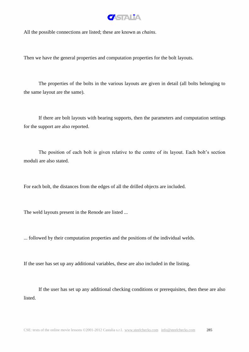
CSE: texts of the online movie lessons ©2001-2012 Castalia s.r.l. www.steelchecks.com [email protected] 285
All the possible connections are listed; these are known as chains.
Then we have the general properties and computation properties for the bolt layouts.
The properties of the bolts in the various layouts are given in detail (all bolts belonging to
the same layout are the same).
If there are bolt layouts with bearing supports, then the parameters and computation settings
for the support are also reported.
The position of each bolt is given relative to the centre of its layout. Each bolt’s section
moduli are also stated.
For each bolt, the distances from the edges of all the drilled objects are included.
The weld layouts present in the Renode are listed ...
... followed by their computation properties and the positions of the individual welds.
If the user has set up any additional variables, these are also included in the listing.
If the user has set up any additional checking conditions or prerequisites, then these are also
listed.

CSE: texts of the online movie lessons ©2001-2012 Castalia s.r.l. www.steelchecks.com [email protected]
We are now at the start of the section on the results of CSE’s automatic checks.
If user checks are required and have been specified in the settings, and if prerequisites have
been defined, then these checks are reported first; CSE performs them before the automatic checks.
During the analysis, if one or more prerequisites have not been met, then the system prompts
for confirmation whether the automatic checks should be run. If the user chooses to abort the
checks, then the listing ends here; otherwise, the results of the subsequent automatic checks follow.
The results for any prerequisites are listed; here, they have been satisfied.
Now we come to the forces acting on the bolt layout at its various extremities, listed in all
combinations and instances. The forces are expressed in the global reference system; they derive
from the finite element model created by CSE in the background to compute the connection. These
forces do not relate to individual bolts but to the entire layouts.
Next, the overall internal forces in the bolt layouts are shown; these are the forces
corresponding to the cross-sections for checking, in all combinations and instances.
This is followed by the internal forces in the individual bolts, in all instances and
combinations, along with the respective coefficients of utilisation according to the selected
standard.
For weld layouts, we have the internal forces in the various combinations and instances,
followed by the stresses in the individual welds and the associated coefficients of utilisation.
For the components, there are various lists, according to what causes the maximum
coefficient of utilisation in the various combinations and instances. These lists include the automatic
FEM checks and the user checks, together with all the other automatic checks that CSE performs.

CSE: texts of the online movie lessons ©2001-2012 Castalia s.r.l. www.steelchecks.com [email protected] 287
For example, if the maximum coefficient of utilisation for a given plate in combination x
and instance y is due to bearing stress, then for that condition, the component will be listed under
“Throughs whose maximum exploitation is due to bearing stresses”. If the maximum coefficient of
utilisation for this plate, in combination j and instance k, is given by the automatic analysis of the
FEM model created by CSE, then this component will be listed under the “Throughs whose worst
exploitation is due to FEM resistance checks” for the condition “combination j and instance k”.
The results of the automatic check on the displacements are included, based on the limit
values set by the user.
Finally, we have a summary of the maximum utilisations computed for the various
components across the different combinations, instances and checks. (*) è necessaria una modifica
del listato
If the listing is produced in cut-down form, then only the essential information is included,
namely a summary of the components (without details of the bolt and weld layouts) and the
utilisation envelope with the maximum values for different combinations and instances.

CSE: texts of the online movie lessons ©2001-2012 Castalia s.r.l. www.steelchecks.com [email protected]
711 COMMANDS: CHECKS – DISPLAY BLOCK-TEAR RESULTS
revisione: dicembre 2011
[versione in italiano – modello: blocktearing_tension.CSE, combi 25]
The “Show block-tear results” command is available both in the Checks menu and as a
button in the side toolbar, when the graphical view is active. [callout]
If the Renode checks include block tearing, and if the selected component’s maximum
utilisation is due to block tearing, then this command will bring up a dialog box showing the results
of the check for this component, in the current combination and instance. [esegui comando]
The image in the dialog box can be printed or copied to the clipboard. It shows the most
critical failure path on the selected component, based on the forces computed in the current
combination and instance. The currently selected face – shown in green – does not necessarily
belong to the component; to select the desired face, simply browse with the arrow buttons
underneath. The failure path terminates on the edges of the component whose results we are
viewing, regardless of the face selected in the dialog box.
In this case, the path computed causes the component to fail as shown in the pop-up. This
path affects only two of the layout’s three bolts; it is the most critical path, even though it is subject
only to a partial resultant. The CSE validation document studies this very case in detail, showing
that the most critical path is indeed the one computed by the program.
On the left, under the basic information, the following results are shown:
- the ultimate strength of the most critical failure path;
- the force applied, which may equate to the resultant of the whole layout or that of a subset of
bolts;

CSE: texts of the online movie lessons ©2001-2012 Castalia s.r.l. www.steelchecks.com [email protected] 289
- the angle of inclination of the applied resultant, according to the convention shown in the
pop-up; [callout] magari scorrere con il mouse per fa vedere il 10-16
]
- the coefficient of utilisation given by the ratio between the force applied and the ultimate
strength of the most critical path.
For a detailed description of how the failure paths are computed and the problems involved,
please see the program user guide.
CSE: texts of the online movie lessons ©2001-2012 Castalia s.r.l. www.steelchecks.com [email protected]
730 COMMANDS: PRENODE – NEW, SAVE revisione: dicembre 2011
[Cmd_Prenodo_Nuovo.CSE; renodo vuoto, vista grafica attiva, solo centri delle facce, pan.renodo]
Before learning how to construct a parametric Renode, it is a good idea to become familiar
with constructing a normal Renode.
In the parametric approach, the main difference concerns how the objects’ quantities and the
other data are defined: instead of entering numbers only, we can also use formulas, expressed in
terms of the Renode’s variables.
The command “New” in the PRenode menu starts the process of recording a parametric
Renode; it can be used when the current Renode is empty: in other words, if no components,
variables or conditions have been added, and no members have been modified. Using this
command, we can create standardised types of node (PRenodes) to save in the archive and use when
we need them. [ click ]
When the command is run, a dialog box appears for us to specify the new PRenode’s name,
the prefix for the associated images, and an optional description and explanation. The class and type
of the bolts to be used also need to be defined, using the button provided. [click bottone]
Once the data have been entered, we can build the Renode in parametric form by clicking
OK. [digitare “esempio” in nome e prefisso immagini, premere OK]
A button is available to save the PRenode during the recording process [callout].
We shall start to build our Renode, which will be a ground joint, by adding a base plate.
[arrivare fino al dialogo delle quote]

CSE: texts of the online movie lessons ©2001-2012 Castalia s.r.l. www.steelchecks.com [email protected] 291
During the recording process, we can define the plate’s dimensions using formulas.
We define the plate’s width as twice the width of member m1; similarly for its height.
[digitare “2*m1.b” e “2*m1.h”] We make the plate as thick as the flange of m1. [digitare “m1.tf]
These data are mere examples to keep things simple; they are not intended to optimise or
design the connection. [callout] We update the image based on the quantities entered. [aggiorna]
We insert the plate into the scene. [...]
We shall not construct the entire connection now, because that is not our aim in this lesson;
we shall save a connection that contains a plate only. First, however, we’ll save an image to
associate with the node once built. [add image]
We save the current PRenode into the archive, using the Save command, and we exit from
parametric mode [salva].
The freshly saved PRenode is now available in the archive. [aprire l’archivio e mostrare,
esci]
We shall now apply the PRenode to a different Renode. We open a new model and quickly
define a ground joint with a similar section of different size, for instance a HEB200. [nuovo
modello, strutture tipiche….]
We apply the PRenode saved earlier. […] As we can see, the plate size has changed for the
current member.

CSE: texts of the online movie lessons ©2001-2012 Castalia s.r.l. www.steelchecks.com [email protected]
Although only a plate has been added in this PRenode, complex PRenodes can be created,
without restrictions on the number of entities or the operations to perform.
An existing PRenode can also be revisited using the Restart command, which is described
in a lesson of its own.

CSE: texts of the online movie lessons ©2001-2012 Castalia s.r.l. www.steelchecks.com [email protected] 293
731 COMMANDS: PRENODE – RESTART revisione: dicembre 2011
[prenodo compatibile vuoto]
The Restart command allows us to add new operations to an existing PRenode from the
archive.
To use this facility, we need to work on an empty Renode that is compatible with the
PRenode that we wish to amend. An “empty” Renode is one with members only, without any
modifications or new components. “Compatible” means that it must have the same topology and
the same types of cross-section as the PRenode that we wish to modify.
Once the command has been invoked, the user is presented with the archive from which to
choose the PRenode to work on. If no PRenode is compatible with the current Renode, then a
warning message is shown. [click]
If there is at least one compatible PRenode, as in this case, then we select the PRenode that
we want, and we apply it, as if assigning a parametric Renode normally. [selezionare prenodo,
OK]
We can edit some of the parameters, if we wish, or we can apply the PRenode as it is. [OK]
The PRenode has now been applied, and we are in recording mode. The dimensions of the
components, the magnitudes of the shifts, and so on, must be defined parametrically. The operations
performed will be saved against the original PRenode, which will therefore contain all the existing
operations as well as the ones just added.

CSE: texts of the online movie lessons ©2001-2012 Castalia s.r.l. www.steelchecks.com [email protected]
As in a normal recording, images can be added, the recording can be paused and resumed,
the PRenode can be saved with its new additions, or the recording can be aborted and the changes
discarded.

CSE: texts of the online movie lessons ©2001-2012 Castalia s.r.l. www.steelchecks.com [email protected] 295
733 COMMANDS: PRENODE – ADD IMAGE revisione: dicembre 2011
[nodo qualsiasi già finito, in modalità restart per avere il comando disponibile]
When recording a parametric Renode, we can use the Add image command on the PRenode
menu to save the current view in JPEG format and associate one or more images with the current
PRenode. [ salva img ] The image must be saved in the CSE installation folder, which is offered
by default. The default name offered for the image consists of the prefix chosen at the start of the
recording process, together with a progressive number (appended automatically).
The command is intended for use after the PRenode has been completed – to create a full set
of useful images for it. Images of extracted views can also be added, along with zooms of details
and anything that may help to document the PRenode.
New images can also be added to an existing PRenode through the archive.

CSE: texts of the online movie lessons ©2001-2012 Castalia s.r.l. www.steelchecks.com [email protected]
735 COMMANDS: PRENODE – PAUSE, CONTINUE, ABORT revisione: dicembre 2011
[nodo qualsiasi già finito, in modalità restart per avere il comando disponibile]
During the process of recording a parametric Renode, the Pause command can be used to
suspend recording and return from parametric mode to standard mode. [click] None of the actions
taken during the pause are recorded in the PRenode. To resume recording, use the Continue
command; this returns control to parametric mode. [click]
During a pause, we can perform operations that we do not want to record, like testing a work
process or making modifications. It is important that these operations do not interfere with the
recording, when we resume. The following example should clarify this. Suppose that, during a
pause, a new component is added – plate P1, for example – and that, on resuming after the pause,
we add a weld layout on that plate. Clearly, applying that PRenode would create an inconsistency,
because we saved the weld layout onto a non-existent component, for this component was defined
during a pause and has not therefore been saved.
Using the Abort command, we can terminate the process of recording a PRenode without
saving it. Any entities, work processes and modifications added will remain on the current Renode,
but they will not be recorded. At the same time, control reverts from parametric to standard mode.

CSE: texts of the online movie lessons ©2001-2012 Castalia s.r.l. www.steelchecks.com [email protected] 297
739 COMMANDS: PRENODE – ARCHIVE revisione: dicembre 2011
[modello qualsiasi, ma anche modello vuoto]
The Archive command, on the PRenode menu, gives access to the archive of parametric
Renodes – or PRenodes – via a dedicated dialog box, which appears when the command is run.
[click su bottone]
All the PRenodes in the archive are listed in the panel on the left. The image shown is the
first one associated with the selected Renode, highlighted in blue. If there are several images
associated with it, then these can be scrolled with the arrow buttons. [click] The Open button opens
the current image in Paint, so that it can be viewed in its actual dimensions and modified (if
desired).
With the Remove button, we can dissociate the current image from the PRenode to which it
relates. We are prompted whether to remove the link or to delete the image as well.
The Add button allows us to associate a new image to the current PRenode, by specifying
the file path.
We now come to the buttons in the “Actions on selected PRenode” section. [callout] We
can save our work by clicking the OK button and discard it by clicking Cancel.
The Remove button deletes the currently selected PRenode; the user is prompted for
confirmation first. Duplicate creates a copy of the selected PRenode and puts it at the end of the list;

CSE: texts of the online movie lessons ©2001-2012 Castalia s.r.l. www.steelchecks.com [email protected]
this copy can then be modified using the Restart command on the PRenode menu or via the
alphanumeric mode. Modify or display initial data brings back the dialog box used to start the
process of recording a new PRenode and specify some preliminary settings. [click] Here we can
change: the name of the current PRenode; the prefix associated with its images; the description; the
explanation; and the bolt class. [esci] Modify operations allows us to modify the current PRenode
alphanumerically. [click] Effectively, this means editing an ASCII text file.
[scorrere su un componente] For example, we can change a component’s dimensions by
altering the text. To save the changes, click OK in this dialog box and again in the main one.
Finally, let’s look at the buttons in the “Actions on archive” section. [callout]
Add new PRenodes from file prompts the user for a text file containing new PRenodes; Save
PRenodes onto a file (txt) enables us to create a text file containing all the PRenodes in the archive.
Using these two commands, and by editing the text files that are created, we have a means of
managing and customising the archive – for example, by organising the PRenodes into different
sub-archives.
Save PRenodes onto a file (bin) allows us to save the current archive into a binary file – as a
backup copy, for instance.
With the command Clear all PRenodes from the archive, we can empty the current archive.
This operation – like adding PRenodes from a file – is confirmed when we click OK.

CSE: texts of the online movie lessons ©2001-2012 Castalia s.r.l. www.steelchecks.com [email protected] 299
801 PROBLEMS: Bearing support – Bearing surface
In this video, we discuss how to define a bearing surface. The concept was introduced in lesson
205, which defines what a bearing support is and what role it plays.
A bearing support works by exchanging normal compressive stresses between two or more
surfaces.
In order that these stresses can be transmitted efficiently, it is essential that the bearing support is
stiff enough.
The contact surface between one plate and another – or between a plate and a constraint block –
can, in general, exert compressive stresses. Its stiffness, however, will generally vary from one
point to another (exactly as a plate’s deformation varies under a constant pressure).

CSE: texts of the online movie lessons ©2001-2012 Castalia s.r.l. www.steelchecks.com [email protected]
The bolt layout’s bending, which the bearing support helps to absorb, is normally exerted by an
initial surface, called the applied load footprint; this is generally the transverse section of a
member. The bending is transferred from this initial surface to the bearing support, thanks to the
bending stiffness of the plate to which the bolt layout is connected. In order that this plate can
successfully transfer the normal stresses involved, it must be sufficiently stiff.
The plate’s stiffness depends on its thickness and on the geometry of the connection. A plate
will be stiff enough in all its points if it is thick enough.

CSE: texts of the online movie lessons ©2001-2012 Castalia s.r.l. www.steelchecks.com [email protected] 301
In this case, the bearing surface can be the entire surface of the plate to which the bolt layout is
connected.

CSE: texts of the online movie lessons ©2001-2012 Castalia s.r.l. www.steelchecks.com [email protected]
A thin plate tends to bend easily, and only a small area of it in the neighbourhood of the applied
load footprint can fulfil the role required. We can improve its stiffness locally by adding stiffening
plates to connect the plate to the member that causes the bending. If enough of these stiffening
plates are used, then the entire surface of the plate – despite its thinness – can successfully transmit
the normal stresses and can thus function properly.
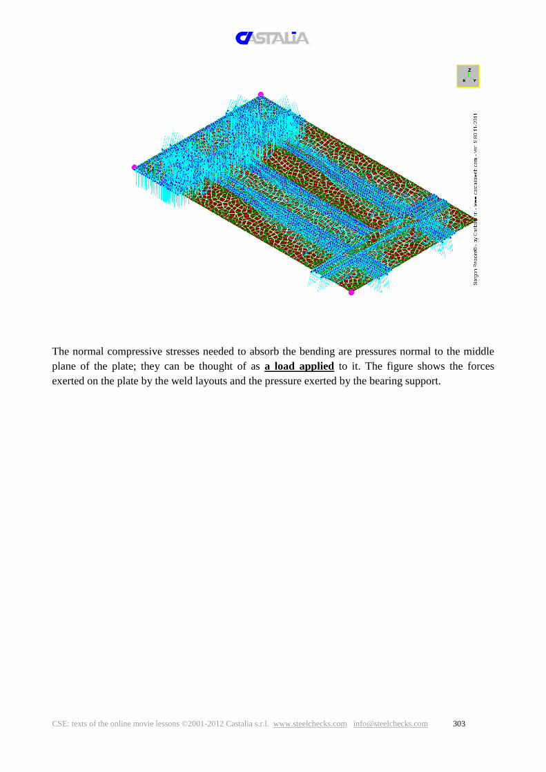
CSE: texts of the online movie lessons ©2001-2012 Castalia s.r.l. www.steelchecks.com [email protected] 303
The normal compressive stresses needed to absorb the bending are pressures normal to the middle
plane of the plate; they can be thought of as a load applied to it. The figure shows the forces
exerted on the plate by the weld layouts and the pressure exerted by the bearing support.

CSE: texts of the online movie lessons ©2001-2012 Castalia s.r.l. www.steelchecks.com [email protected]
A model adopted by the most recent standards offers a very useful aid to understanding which part
of the plate may act as a bearing support; in this approach, the surface of the applied load footprint
is extended by a certain width around the edge, determined by the plate’s thickness and by other
parameters. In this model, the stiffness is required only in part of the plate, namely that obtained
using this geometrical construction.

CSE: texts of the online movie lessons ©2001-2012 Castalia s.r.l. www.steelchecks.com [email protected] 305
In a cantilevered beam, the stiffness depends on the inverse of the cube of the beam’s span. The
shorter the beam, the greater its stiffness. The same consideration applies to the plate to which
the bolts are connected.

CSE: texts of the online movie lessons ©2001-2012 Castalia s.r.l. www.steelchecks.com [email protected]
The cantilevered beam’s span is comparable to the width to be added to the surface of the applied
load footprint. This span depends directly on the thickness of the plate.

CSE: texts of the online movie lessons ©2001-2012 Castalia s.r.l. www.steelchecks.com [email protected] 307
When stiffening plates are present, the surface of the applied load footprint is not just that of the
member’s transverse section: it includes the contact surfaces of the stiffening plates as well. The
figure shows two long stiffening plates connecting the column to the base plate. The adjacent white
rectangles represent the welds.
These issues must be considered when we define the bearing surface; the designer is responsible
for specifying a realistic bearing surface. CSE provides the user with a full set of tools for
defining it. It may be one of the coplanar faces in contact, perhaps with a suitable additional border,
or it may be the result of any sequence of Boolean operations applied to surfaces of this type.
CSE determines the extent of the portion to be considered, in the neighbourhood of an applied load
footprint, using the formula in Eurocode 3.
Let’s reflect for a moment about what can happen if the designer specifies the bearing surface
incorrectly – for example, as the entire contact surface of a fairly thin plate without stiffeners.

CSE: texts of the online movie lessons ©2001-2012 Castalia s.r.l. www.steelchecks.com [email protected]
In this case, the entire contact surface needs to resist the compressive stresses. The non-linear
computation will say which part of the surface will be under compression (and therefore reacting)
and which part will be under tension (and therefore not reacting). Here, the yellow area is the
reacting part.

CSE: texts of the online movie lessons ©2001-2012 Castalia s.r.l. www.steelchecks.com [email protected] 309
When the plate’s resistance is checked using the FEM model, however, the compressive stresses
exerted by the bearing support will become normal pressure loads in the model of the plate,
which will be bent. Note the (unscaled) forces corresponding to the normal pressure exerted on the
plate in turn in the compressed area of the bearing support, shown in yellow in the previous image.

CSE: texts of the online movie lessons ©2001-2012 Castalia s.r.l. www.steelchecks.com [email protected]
There will be a certain set of stresses on the compressed side of the plate (Von Mises stresses),
depending on the pressures on the bearing support and, of course, on the plate’s thickness and on
the mesh used for the computation. If the plate is too thin, then it will bend excessively and will not
be able to bear the load. In this example, the welds are considered as clamps (magenta-coloured
dots).
We can now see what would have happened if the bearing surface had been a smaller surface,
consisting of the applied load footprint with a border added around it, as illustrated.

CSE: texts of the online movie lessons ©2001-2012 Castalia s.r.l. www.steelchecks.com [email protected] 311
The non-linear computation would have given a different compressed area, typically closer to the
welds. The reacting part, in yellow, is clearly not a rectangle but T-shaped.
This is how it compares to the previous situation.

CSE: texts of the online movie lessons ©2001-2012 Castalia s.r.l. www.steelchecks.com [email protected]
The part of the plate under compression is now smaller, and the Von Mises stresses in it do not
exceed the yield value.
To sum up: if we choose a larger bearing surface than is realistic, then the plate will be under much
greater stresses, because the areas of normal pressure will be much larger than necessary.
The next lesson discusses the constitutive law for the bearing support.

CSE: texts of the online movie lessons ©2001-2012 Castalia s.r.l. www.steelchecks.com [email protected] 313
802 PROBLEMS: Bearing support – constitutive law for the bearing
support
Once a bearing surface has been defined, we also need to specify its constitutive law.
The bearing support exerts a distribution of normal compressive stresses through the bearing
surface; this distribution combines with the tensions in the bolts to balance the axial force and the
bending applied to the bolt layout.
These compressive stresses observe a uniaxial constitutive law that governs the stresses and the
deformations. The distribution and the magnitude of the compressions depend on how this
constitutive law is defined.
For a given bearing surface and number of bolts, the combined tension and bending or the
compression and bending applied is balanced differently depending on the uniaxial constitutive
laws used for the bolts and for the bearing support. The computation is non-linear.
The constitutive law for the bolts is elastic-perfectly-plastic. Therefore, if one or more bolts reach
the yield stress, then the computation redistributes the tensions from the bolts that have yielded to
those that still have not. If all the bolts have yielded, then the load exceeds its allowed limit, and
convergence is not possible. In this case, the bolt layout cannot sustain the forces applied.

CSE: texts of the online movie lessons ©2001-2012 Castalia s.r.l. www.steelchecks.com [email protected]
The bearing support’s constitutive law is no-tension and is therefore always non-linear. Only part
of the bearing surface reacts; the rest of it does not. The compressed zone can react, in the part
under compression, according to a linear or a non-linear constitutive law.
If the compressed part is linear, then we need to state the factor m that, when multiplied by the
bearing support’s modulus of elasticity, Ec, gives the modulus of elasticity for the bolts. If m is
large, then the bearing support is less rigid than the bolts; if m is small (less than 1 – even
significantly so), then the bearing support is more rigid than the bolts.
As m increases, the part of the bearing surface affected by the compressive stresses increases in
size; indeed, for the same deformations, the normal compressive stresses exerted by the bearing
support become smaller.
Conversely, as m decreases, the part of the bearing support affected by the compressive stresses
decreases in size, although the stresses exerted become greater.

CSE: texts of the online movie lessons ©2001-2012 Castalia s.r.l. www.steelchecks.com [email protected] 315
Users can define not only linear laws but also elastic-perfectly-plastic, parabola-rectangle or
trilinear laws for the bearing support.
Sometimes, a bolt layout anchored to a plate that is subject to bending may exert a rotational force
on it about one of its corners. This behaviour can be simulated using a constitutive law that makes
the bearing support much stiffer than the bolts (for instance, by setting m=0.01, or 0.001 if linear).
To see what this means, let’s suppose that the bearing surface is shaped like this.

CSE: texts of the online movie lessons ©2001-2012 Castalia s.r.l. www.steelchecks.com [email protected]
And let’s start by setting m=1.
In a combination where there is only bending moment at the section’s elastic limit, we obtain the
following distribution:
If we now set m=0.01 and repeat the computation, with the same forces and the same bearing
surface, then we obtain the following:

CSE: texts of the online movie lessons ©2001-2012 Castalia s.r.l. www.steelchecks.com [email protected] 317
In effect, this simulates the rotation about the lower side of the bearing surface. The affected part of
the bearing surface is much, much smaller, yet the peak stress is almost 10 times greater (4.375
times the bearing support’s limit stress, compared to 0.495 times in the previous case).
Now let’s set m=10, considering the elastic modulus of the bearing support to be one tenth that of
the bolts.
The resulting distribution is as shown. The part of the bearing surface under compression is larger;
the peak stress is lower (0.210); and the normal stress level of the tension bars is much greater
(because the arm of the internal couple is now smaller).

CSE: texts of the online movie lessons ©2001-2012 Castalia s.r.l. www.steelchecks.com [email protected]
805 PROBLEMS: Shear-only bolts
When designing connections, we often need to consider bolt layouts acting through a resistance
mechanism under which the bolt shafts are ideally not under tension or compression. Such bolt
layouts can withstand only shears and twisting moments (in other words, only offset shears), by
means of a shear in the bolt shafts.
Such bolt layouts are described as shear-only; we can deploy them by ticking a dedicated field in
the dialog box used to add or modify bolt layouts.
Shear-only bolt layouts have very limited bending stiffness in the CSE computation model. If a
bending moment acts on such a bolt layout, then unless the moment is very small, it will cause high
displacements – even if the bolt shafts are only subject to the tension and compression forces that
are essential to maintain equilibrium.
When this happens, the bolt layout cannot work on a shear-only basis; instead, it must be treated
as capable of withstanding bending moments too (it must not be shear-only).
Theoretically, there are only two ways for a bolt layout to be shear-only: either bending moments
are absent or they are absorbed by other shear-only bolt layouts or other joiners that work together
to absorb them.
In reality, no bolt layout is free of bending moments. Even where normal technical practice is to
neglect the weak moments of transport of the shears, caused by the (albeit modest) plate
thicknesses, these moments do exist in CSE’s computation model, and they give rise to (generally
modest) bending moments. Besides, a shear always generates a bending moment at a certain
distance.
[colonna con cerniera alla base]
If the bolt layout is iso-connected, or statically determined (see lesson 810), and if the connection
is completely free of bending moments (as in a hinge), then the bolt layout may be shear-only.
[collegamento a squadretta trave-trave, incernierata]
If the bolt layout is iso-connected, and if there are very small bending moments – due to the
transport of the computation shears over small distances – then we have two options.

CSE: texts of the online movie lessons ©2001-2012 Castalia s.r.l. www.steelchecks.com [email protected] 319
Either we leave the bolt layout as shear-only, neglecting the potentially high displacements
highlighted by the software;
or we transform the bolt layout into a non-shear-only bolt layout, but without specifying any
bearing support. In this case, the (parasitic) bending due to the transport will be absorbed by a
modest tension and compression in the bolt shafts; this will not invalidate the checking
computation.
If the bolt layout is hyper-connected and several bolt layouts work together to bear all the
computation forces, then the bolt layouts may be shear-only – but only if the bending moments in
the computation are absorbed by two or more bolt layouts that (although shear-only) bear the
bending moment applied essentially by a couple of forces (shears in the bolt layout).
If there are no such cooperating bolt layouts – or if there are, but they are poorly arranged – then
the program computes highly significant displacements; the designer will then need to revisit the
connection design.

CSE: texts of the online movie lessons ©2001-2012 Castalia s.r.l. www.steelchecks.com [email protected]
810 PROBLEMS: Flexibility index for bolt layouts
Generally, most bolt layouts fulfil a precise static function, and the stresses on them can be
determined by simple considerations of equilibrium. Such a bolt layout is said to be iso-connected
(or statically determined).
Otherwise, where several bolt layouts combine to bear a certain set of stresses, the layout is said to
be hyper-connected (or statically indeterminate).
Experimental investigation has shown that the stresses borne by a hyper-connected bolt layout
depend also on complex factors like bearing stress (the plasticization of the sheet due to shear in the
bolt shafts), friction and the play between the bolts and the holes.
Forces borne globally by two or more bolt layouts therefore tend to be redistributed between
layouts; they migrate from the bolt layout that caused the bearing stress in the sheet or that has a
greater play between bolts and holes.
The computation methods currently in general use tend to address these complex phenomena in a
conventional and one-size-fits-all manner; to take them into account properly, CSE has introduced
the concept of the flexibility index for a bolt layout.
For each bolt layout in CSE, a native stiffness can be computed that depends on various factors,
like the number of bolts, their separation, their diameter, and the bolt layout’s position. If a bolt
layout’s flexibility index left unchanged as the default value of 1, then the forces that two or more
bolt layouts must bear are distributed among them in proportion to their native stiffnesses.
In certain cases, the plasticization and redistribution that we have just mentioned cannot be dealt
with properly just by sharing the stresses between the various bolt layouts, as predicted by native
stiffnesses.
To modify how the stresses at a set of hyper-connected bolt layouts are shared out, we can increase
the flexibility index for one or more bolt layouts, thus reducing their stiffness from their native
value. This simulates the redistribution due to the plasticization that we mentioned.

CSE: texts of the online movie lessons ©2001-2012 Castalia s.r.l. www.steelchecks.com [email protected] 321
In some cases, therefore, it can help to increase the flexibility index for certain bolt layouts from the
initial value of 1 up to 3, 5, 10 or more.

CSE: texts of the online movie lessons ©2001-2012 Castalia s.r.l. www.steelchecks.com [email protected]
820 PROBLEMS: Checking stiffeners
In CSE, stiffeners are components that transmit forces from one part of a component to another part
of the same component.
They must not be confused with the stiffening plates or components that connect different
components.
What we are referring to are mostly stiffeners for I- or H-sections
or reinforcing plates, such as for webs (in moment-resisting connections).
Neither the stiffeners themselves nor the joiners used with them are subject to CSE’s automatic
checks.
Normally, stiffeners do not need to be checked numerically; they are simply sized appropriately,
generally according to the dimensions of the component that they stiffen.
Nevertheless, they can be checked by CSE, when necessary:
by suitable custom user checks or standard checks;
through the FEM check on the component that they stiffen.
It is the user’s responsibility to ensure that these components are checked when required.

CSE: texts of the online movie lessons ©2001-2012 Castalia s.r.l. www.steelchecks.com [email protected] 323
825 PROBLEMS: FEM modelling – general remarks
Although the checks on bolts and welds follow established rules that are essentially well defined
and standardised, the checks on the components are much more complex. This is because the
resistance mechanisms that arise in a component depend on its form, on its dimensions, and on how
it is connected to the other components.
Other checks (bearing stress, punching, member net sections, etc.) can be formalised, to a certain
extent. Others are so complex and general that a full finite element model of the component is
useful for stress analysis purposes.
This approach is not mentioned in the standards, because a T-stub model is usually recommended
instead, despite its clear defects and failings. Firstly, it lacks generality – bolts must be regularly
arranged in two rows, etc. Secondly, the simplification involved – compared to actual practical
problems – is drastic. Thirdly, it is unwieldy and computationally complex. The T-stub-model
approach involves a limit analysis using slip-line theory.
The finite element method has advantages and disadvantages.
One disadvantage is the computation time, although it can be reduced using sparse-matrix solvers
like CSE’s, especially in elastic scenarios. Another disadvantage is the need to examine the stress
analysis results in order to decide whether the entity is acceptable in engineering terms.
Furthermore, the FEM model of the components is conventional, and to a certain extent –
specifically for welded and bolted connections – it is still subject to ongoing research.
Its greatest advantage is generality, which enables us to address any problem in an essentially
precise manner (within the limits of a numeric approach). Although the models are conventional,
both the bolts and the welds can be modelled to give good safety results. The stress maps are,
therefore, a much more sophisticated and accurate tool than T-stub models, which refer to
elementary stress scenarios and are geometrically not very general.
In the checking approach that uses finite element modelling, we need to remember that some
potential failure modes are already considered by other checks, like bearing stress or block tearing.

CSE: texts of the online movie lessons ©2001-2012 Castalia s.r.l. www.steelchecks.com [email protected]
Unlike the approach envisaged by the standards, no load limit is calculated for comparison with the
applied load. The applied load is applied to the entity, and we examine the resulting state of stress to
judge if it is acceptable.
In the T-stub checks under Eurocode 3, part 1-8, the check involves applying somewhat simplified
limit domains between the elementary components of stress. For example, if there is an axial force
and a moment, then the limit axial force and the limit moment are evaluated, then a limit domain is
defined by linearising.
On the other hand, the FEM checks apply the axial force and the bending moment of each
combination at the same time (as well as any other stresses present), to determine the corresponding
state of stress. The approaches are therefore completely different, even though they are doing the
same thing, from an engineering standpoint. Even if not explicitly provided for under the standards,
the checking approach that uses a FEM model is more rigorous, by definition, and aims to achieve
the same results.

CSE: texts of the online movie lessons ©2001-2012 Castalia s.r.l. www.steelchecks.com [email protected] 325
826 PROBLEMS: FEM modelling – linear vs non-linear
The usual approach in the most recent standards is to compute the limit (plastic) forces and compare
them with the existing ones. Yet the existing forces will not necessarily fully plasticize a
component.
It is always good to run the linear analysis first, because it is much simpler and faster than a non-
linear one. This helps us determine whether the entity has reached its plasticization limit.
Given that bearing stress is already taken into account in other checks, minor plasticizations around
the nodes that simulate the bolts are normally acceptable. Even if there are stress peaks around these
nodes, we shall not discard the entity.
Conversely, if plasticization affects large areas of the component, then we can conclude that a linear
analysis will not be enough. It is not always useful, however, to start with a non-linear analysis.
This is because, when plasticization spreads in an elastically calculated entity, it is likely that a non-
linear analysis would also have the same outcome: discarding the entity and redesigning it.
The non-linear analysis can be useful when the plasticization predicted by an elastic computation is
moderate – when it is not confined merely to the areas around the bolts or welds, but nor does it
spread across the entity’s entire surface.
Therefore, it will be useful here.
The non-linear analysis is longer than the linear one, because the computation is iterative.
There are two basic approaches, depending on the constitutive law used for the metal.
Under the elastic-perfectly-plastic constitutive law, the analysis aims to achieve convergence using
the full applied load. If this occurs, then the load limit has not been exceeded, and the component is

CSE: texts of the online movie lessons ©2001-2012 Castalia s.r.l. www.steelchecks.com [email protected]
acceptable. On the other hand, if the applied load is not reached (because the solution diverges), or
if it is reached but only with unacceptable displacements, then the component must be redesigned.
If we use a hardening constitutive law, then convergence will be achieved anyway, and there will be
two conditions to examine. One is to check that the ultimate stress is not reached at any point. The
other is to establish that the displacements under the applied loads are not excessive.
For a component whose FEM model has been created, we analyse its state of stress by considering
its Von Mises stresses. This is done by the Sargon Reader utility program, which is supplied with
CSE. The available functionality includes the ability to view the Von Mises stress envelope map for
all combinations. This immediately tells us the peak stresses that have been reached, and in which
areas and combinations they occur.

CSE: texts of the online movie lessons ©2001-2012 Castalia s.r.l. www.steelchecks.com [email protected] 327
830 PROBLEMS: Selecting your checks and how to run them
The choice of which checks to perform and how to perform them is a crucial step for any
designer of connections, irrespective of CSE.
CSE provides a full toolset for simplifying, speeding up and enhancing the connection designer’s
work. Except for the provision of standard ready-made PRenodes, it cannot do the designer’s job
for them (and does not try to).
Depending on the problem in hand, some checks will need to be made, while some can be omitted.
The checks made depend also on the types of weld layout chosen and how the bolt layouts are
going to work.
Some checks are automatic and require no user intervention at all. Others need the user to enter
information.
Once a bolt layout’s mode of operation has been decided, the bolt checks in CSE are fully automatic
and require no user intervention at all. This also applies to weld layouts.
The components, members and force transferrers/cleats, joined by bolt and weld layouts, may
actually need a great many different checks, depending on how they are constructed and the static
role that they play.
The bearing-stress checks are automatic and may be run or omitted, according to requirements.
The punching checks are also automatic and may be run or omitted.
The block-tear checks are automatic and may be run or omitted. Because block tearing is an
extremely complex problem, users should check that the failure path found by the program is
acceptable.
The group of “component strength checks” offers numerous potential local checks, depending on
the problem in hand. The user is responsible for deciding which checks need to be run and which
can be omitted; CSE offers a huge range of automatic and semi-automatic tools to cover any
eventuality.

CSE: texts of the online movie lessons ©2001-2012 Castalia s.r.l. www.steelchecks.com [email protected]
The member net-section checks belong to this group; they are automatic and are run on
request.
The component FEM checks are automatic and are run on request. They are for complex
problems and very important components. They also belong to this group of checks.
The standard checks include special checks that belong to this group; they are run on
request, as user checks.
The simplified checks on the force transferrers/cleats belong to this group and are useful
for certain types of entity. They are run on request only.
User checks can always be added to provide particular checks in this group. They are also
run on request only.
The group of “component stability checks” is restricted to a small number of cases, given that they
are usually addressed implicitly in determining the relative sizes of the entities. There are two ways
to perform this kind of check in CSE:
some standard checks cover specific stability checks: for example, the stability of the web
panel;
user checks can be added for any special stability checks that may become necessary.
Many checks do not involve computations but are automatically fulfilled when the user gives
the components the correct sizes.
The vast majority of the checks that require computations are supported by CSE as standard. There
are cases, however, where the user must add some checks via the “user checks” tool.
Ready-made parameterized nodes should also contain all the settings needed to perform all the
checks.

CSE: texts of the online movie lessons ©2001-2012 Castalia s.r.l. www.steelchecks.com [email protected] 329
840 PROBLEMS: Parameterizing Renodes
Parameterizing Renodes is an important feature of CSE. It enables users to create parametric
Renodes for application to whole families of empty Renodes.
One obvious group of settings to consider when parameterizing involves the physical dimensions
of the components. These dimensions can be expressed using formulas instead of numbers. These
formulas can use not only the predefined variables but also those added by the user.
For bolt layouts, the number of bolts and their diameter can be parameterized, and so can the
separation between the rows and columns or the layout type. The choice of the bolt layout’s
static operation, the bearing surface and other information are also parameterizable.
For weld layouts, the number of welds, their length and thickness can be set as parameters.
So can the spatial arrangement of the components, in that the layout can be tailored to suit the
different situations at each of the Renodes to which the PRenode can be applied.
And it’s not only the PRenode’s geometrical construction that can be parameterized. So can the
choice of checks and the addition of user variables and standard or user checks.
The use of parameters allows CSE to create complete, ready-to-use Renodes quickly and easily.
This feature is also available in the LIGHT version of the program (that is, the availability of ready-
to-use PRenodes).
Parameterization requires an effort to generalise the design, given that we are describing not a
single, individual Renode but rather an entire family. Designers have the freedom to use different
parameterizations, depending on their needs.


CSE: texts of the online movie lessons ©2001-2012 Castalia s.r.l. www.steelchecks.com [email protected] 331
901 Defining a node with the light version Revisione: novembre 2011
[CSE LIGHT, modello vuoto]
Two steps are needed to define a node with the LIGHT version of CSE, starting from a new
model. The first one is the choice of a structural scheme among the available ones, with the
definition of material and the cross-sections. The second step is the assignation (assignment)
of a predefined node of the archive, with the automatic addition of bolts, welds, plates or
other components according to the chosen node. These predefined nodes are parametric, in
order to fit current sizes; the user can modify desired parameters.
Use the command “Typical nodes” to define the structural scheme. This command is under
the menu called “Nodes” and there is also a button in the bar. It is available if the graphical
view is active. Just click it to activate it. [click vista grafica] [click typical nodes]
A property sheet shows all the available schemes. Now we are going to define, for example, a
beam-column joint. [click] Red members are the masters of each node. Choose the node
with a column and two beams. [click secondo schema]
Use this dialog box to define members properties.
It is possible to add a new material or to browse the archive. All the members will have the
same material (with the light version it is not possible to define different materials for the
members of the same node).
Now browse the archive [click] and apply the S235. [applica il materiale]
It is possible to add new cross-sections or choose from the archive. Now browse the archive
[click] set a filter on HEB type [click] and see all the available cross-sections [click]
Apply, for example, the HEB 280. [click]
This cross-section is now the current one. Apply it to member 1, which is the column. [click]

CSE: texts of the online movie lessons ©2001-2012 Castalia s.r.l. www.steelchecks.com [email protected]
Now set as current section an IPE shape. [click, IPE270] Assign IPE 270 to the beams.
[click - click]
It is possible to define hinged connections between the slaves and the master.
It is also possible to apply a rotation of 90 degrees to the cross-sections, if the corresponding
boxes are unticked.
Click OK to get the node. [ok]
If the model was not saved at the beginning, the program asks to save it now. [salva]
Now we have a “blank” node, with unconnected and overlapping members. The next step is
the assignation (assignment) of a predefined parametric node choosing it from the archive.
Here this operation is briefly shown; see movie 6 9 8 for more information.
Use the command “Assign p-renode”. [click] All the available parametric nodes similar to
current node are shown in the list. Choose one of them and assign it. [ultimo collegamento,
OK] Parameters can be modified during the automatic assignation (assignment); now just
leave default values. [OK]
The node is ready for a control by the user, and then for the setting and the execution of the
automatic checks.