steam products - watts water technologies, inc. - innovative water
TRANSCRIPT

Steam Products
w a t t s . c o m
Table of ContentsGeneral Information
Steam Traps . . . . . . . . . . . . . . . . . . . . . . . . . . . . . . . . . . . . . . . . . . . . . . . . . . . . . . . . . . 1-2Selection Guide . . . . . . . . . . . . . . . . . . . . . . . . . . . . . . . . . . . . . . . . . . . . . . . . . . . . . . . 2-3A Guide to Steam Loss . . . . . . . . . . . . . . . . . . . . . . . . . . . . . . . . . . . . . . . . . . . . . . . . . 4-5
Steam TrapsG, GH, MG, MGH – Thermostatic Radiator Steam Traps . . . . . . . . . . . . . . . . . . . . . . . . 6QF – Quick-Fix™ Radiator Steam Trap Replacement Kits . . . . . . . . . . . . . . . . . . . . . . . 7WFT – Float & Thermostatic Steam Traps . . . . . . . . . . . . . . . . . . . . . . . . . . . . . . . . . . 8-9WFTC, WFTK – F&T Steam Trap Cover Assemblies and Repair Kits . . . . . . . . . . . . . . 9G, MG – Float & Thermostatic Steam Traps. . . . . . . . . . . . . . . . . . . . . . . . . . . . . . . 10-11WIB – Inverted Bucket Steam Traps. . . . . . . . . . . . . . . . . . . . . . . . . . . . . . . . . . . . . 12-13WTD 600 – Thermodynamic Steam Traps . . . . . . . . . . . . . . . . . . . . . . . . . . . . . . . . . . . 14
Steam Safety Relief ValvesFig. 31, 41, 41A – Bronze and Cast Iron Safety Relief Valves. . . . . . . . . . . . . . . . . . . . 15315, 415 – Steam Safety Relief Valves . . . . . . . . . . . . . . . . . . . . . . . . . . . . . . . . . . . . . . 16
Steam Process Regulators127 – Process Steam Pressure Regulators . . . . . . . . . . . . . . . . . . . . . . . . . . . . . . . . . 17152A, 252A – Process Steam Pressure Reducing Valves . . . . . . . . . . . . . . . . . . . . . . . 18Capacity Charts . . . . . . . . . . . . . . . . . . . . . . . . . . . . . . . . . . . . . . . . . . . . . . . . . . . . . 19-20
Steam Accessories142 and 144 Process Boiler Water Feeders . . . . . . . . . . . . . . . . . . . . . . . . . . . . . . . . . 21
Teflon® is a registered trademark of E.I. Dupont de Nemurs Co, Inc.Watts product specifications in U.S. customary units and metric are approximate and are provided for reference only. For precise measurements, please contact WattsTechnical Service. Watts reserves the right to change or modify product design, construction, specifications, or materials without prior notice and without incurring any obli-gation to make such changes and modifications on Watts products previously or subsequently sold.
IntroductionWatts has been a leader in steam management technology and products since 1874. Steam products performunder severe conditions requiring high quality performance and quick in-line maintenance. We recognize theimportance and value of designing high quality, longer service life features for these types of products. All oursteam products are engineered to exceed established standards. This brochure describes the full line of Wattssteam products designed to provide cost effective, efficient steam system solutions.
General Information
1
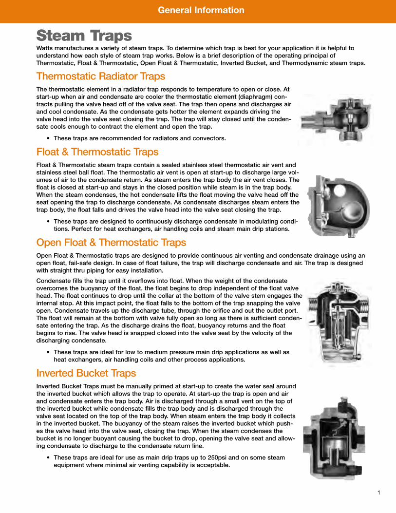
Steam TrapsWatts manufactures a variety of steam traps. To determine which trap is best for your application it is helpful tounderstand how each style of steam trap works. Below is a brief description of the operating principal ofThermostatic, Float & Thermostatic, Open Float & Thermostatic, Inverted Bucket, and Thermodynamic steam traps.
Thermostatic Radiator TrapsThe thermostatic element in a radiator trap responds to temperature to open or close. Atstart-up when air and condensate are cooler the thermostatic element (diaphragm) con-tracts pulling the valve head off of the valve seat. The trap then opens and discharges airand cool condensate. As the condensate gets hotter the element expands driving thevalve head into the valve seat closing the trap. The trap will stay closed until the conden-sate cools enough to contract the element and open the trap.
• These traps are recommended for radiators and convectors.
Float & Thermostatic TrapsFloat & Thermostatic steam traps contain a sealed stainless steel thermostatic air vent andstainless steel ball float. The thermostatic air vent is open at start-up to discharge large vol-umes of air to the condensate return. As steam enters the trap body the air vent closes. Thefloat is closed at start-up and stays in the closed position while steam is in the trap body.When the steam condenses, the hot condensate lifts the float moving the valve head off theseat opening the trap to discharge condensate. As condensate discharges steam enters thetrap body, the float falls and drives the valve head into the valve seat closing the trap.
• These traps are designed to continuously discharge condensate in modulating condi-tions. Perfect for heat exchangers, air handling coils and steam main drip stations.
Open Float & Thermostatic TrapsOpen Float & Thermostatic traps are designed to provide continuous air venting and condensate drainage using anopen float, fail-safe design. In case of float failure, the trap will discharge condensate and air. The trap is designedwith straight thru piping for easy installation.
Condensate fills the trap until it overflows into float. When the weight of the condensateovercomes the buoyancy of the float, the float begins to drop independent of the float valvehead. The float continues to drop until the collar at the bottom of the valve stem engages theinternal stop. At this impact point, the float falls to the bottom of the trap snapping the valveopen. Condensate travels up the discharge tube, through the orifice and out the outlet port.The float will remain at the bottom with valve fully open so long as there is sufficient conden-sate entering the trap. As the discharge drains the float, buoyancy returns and the floatbegins to rise. The valve head is snapped closed into the valve seat by the velocity of thedischarging condensate.
• These traps are ideal for low to medium pressure main drip applications as well asheat exchangers, air handling coils and other process applications.
Inverted Bucket TrapsInverted Bucket Traps must be manually primed at start-up to create the water seal aroundthe inverted bucket which allows the trap to operate. At start-up the trap is open and airand condensate enters the trap body. Air is discharged through a small vent on the top ofthe inverted bucket while condensate fills the trap body and is discharged through thevalve seat located on the top of the trap body. When steam enters the trap body it collectsin the inverted bucket. The buoyancy of the steam raises the inverted bucket which push-es the valve head into the valve seat, closing the trap. When the steam condenses thebucket is no longer buoyant causing the bucket to drop, opening the valve seat and allow-ing condensate to discharge to the condensate return line.
• These traps are ideal for use as main drip traps up to 250psi and on some steamequipment where minimal air venting capability is acceptable.

General Information
2
Steam Trap Selection GuideMain Drip ApplicationsA main drip trap should be used every 100-150 feet of straight piping run. Traps should be used at each change ofpiping elevation and at risers as well as in front of expansion loops. The condensate load in a typical main drip appli-cation is small. It is unusual for main drip steam traps to be larger than 3⁄4" (20mm).
PSI Range Applicable Products0-75psi WFT, WIB76-125psi WTD 600, WFT, WIB126-250psi WTD 600, WIB251-600psi WTD 600
Thermodynamic TrapsAt start-up, air and condensate under pressure raise the disc off of the valve seat openingthe trap allowing discharge into the condensate return line. Hot condensate flashes tosteam as it goes through the trap body. The velocity of the flash steam creates a lowerpressure area under the disc causing the disc to seat. The pressure of the flash steam inthe cap keeps the disc on the valve seat, closing the trap. The trap remains closed untilthe flash steam condenses allowing system pressure to raise the disc off of the valve seat.
• These traps are ideal for use as high pressure main distribution line traps from 75-600psi.
Steam Main
Collection Leg
SteamTrap Check
Valve
To Condensate Return
Watts Strainer77SI
AC
Size of Collection LegSteam Main Diameter A
1⁄2" to 4" (13 to 102mm) Same as main
5" (127mm) & larger 2 to 3 pipe sizes smallerthan main, but never small-er than 4" (102mm)
Length C of collection legAutomatic Start Up:
Length to be 28" (711mm) or more
Supervised Start Up:Length to be 11⁄2 times steam main diameter, but never
shorter than 8" (203mm).
Typical Steam Main Drip Station
General Information
3
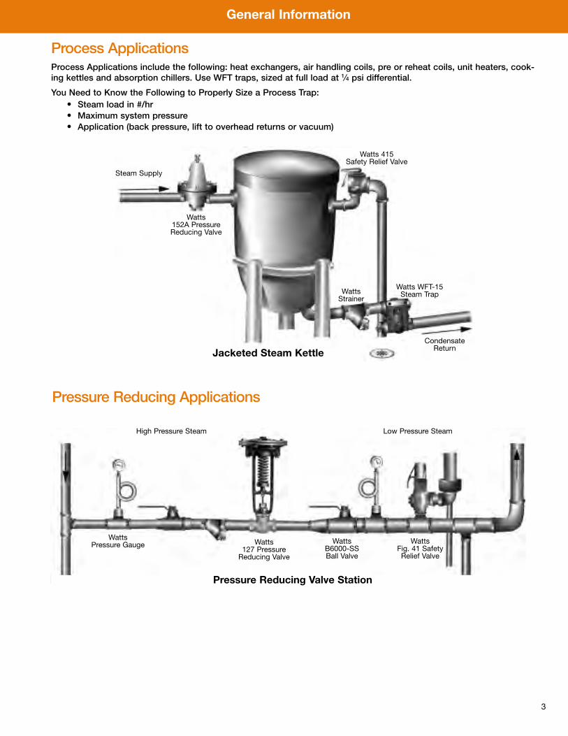
Process ApplicationsProcess Applications include the following: heat exchangers, air handling coils, pre or reheat coils, unit heaters, cook-ing kettles and absorption chillers. Use WFT traps, sized at full load at 1⁄4 psi differential.
You Need to Know the Following to Properly Size a Process Trap:• Steam load in #/hr• Maximum system pressure• Application (back pressure, lift to overhead returns or vacuum)
Jacketed Steam Kettle
Steam Supply
Watts 415Safety Relief Valve
Watts Strainer
Watts WFT-15Steam Trap
Watts 152A PressureReducing Valve
CondensateReturn
Pressure Reducing Applications
Watts 127 PressureReducing Valve
Watts B6000-SSBall Valve
Watts Fig. 41 SafetyRelief Valve
Low Pressure SteamHigh Pressure Steam
Watts Pressure Gauge
Pressure Reducing Valve Station
General Information
4
A Guide to Steam LossFaulty Steam Traps Are Leaking MoneyThe constant drive for energy conservation combined with the continual rise in energy costs has motivated colleges,universities, hospitals and other large facilities throughout the U.S. to become more aware of energy waste. In spiteof this, institutions often overlook one particular area: the steam system. This is because steam systems appear tobe functioning well. This perception may be misleading because the steam system may still be wasting significantamounts of energy and money. The problem — a well designed and properly installed steam system is inherentlyefficient and forgiving of bad maintenance practices. Thus, small defects can go unnoticed, while efficiency gradual-ly degrades. Meanwhile, the accompanying increase in operating cost is easily lost in the overall costs of operatinga facility.
Looking For The Sources of LeakageSteam traps are perhaps the single major source of steam loss. This is because there are so many of them on a sys-tem and because they connect directly to the condensate return system. In large systems, individual traps may failwith little significant impact. But the collective waste of several faulty traps can push the cost of energy out of sight.
Problems with Vacuum Return SystemsIn the condensate return system, steam injected by a leaking steam trap can cause severe operational problems byraising the temperature and the pressure of the return system. This can be particularly troublesome if a vacuumreturn system is used because it is virtually impossible to maintain a vacuum with steam leaking into the return lines.Proper steam and condensate circulation through the entire system is hampered or prevented. Operators try torestore the proper circulation by raising the pressure in the boiler, consuming more energy and driving up operatingcosts. So, if your system shows a loss of vacuum or pressure at the vacuum pump, it is a signal that steam is comingdirectly from the supply section into the return section.
Using a Condensate PumpIn systems using a condensate pump only, steam escaping into the condensate return line raises the condensatetemperature to a point where it cannot be handled by the centrifugal condensate pump. Cavitation, noise and pumpseal leaks are imminent if condensate temperatures are not brought to a reasonable level. In such cases, the pumpsimply cannot return the condensate to the boiler. Excessive temperatures at the condensate pump can be detectedby noting the character of the discharge at the pump vent. With temperatures in the proper operating range (less than190˚F), there should be no noticeable discharge from the vent. An occasional wisp of vapor is acceptable.
Figuring Loss in Dollars and CentsHow much can leaking traps cost in wasted energy? It depends on the system’s steam pressure (psi), the cost of thesteam, and the number of traps involved. The example illustrated on the graph on page 5 indicates that one 1⁄4" orificeon a 2psi system could cost the owner $478.80/trap every year. An older steam system used on a large campus couldeasily incorporate a hundred or more such traps.
General Information
5
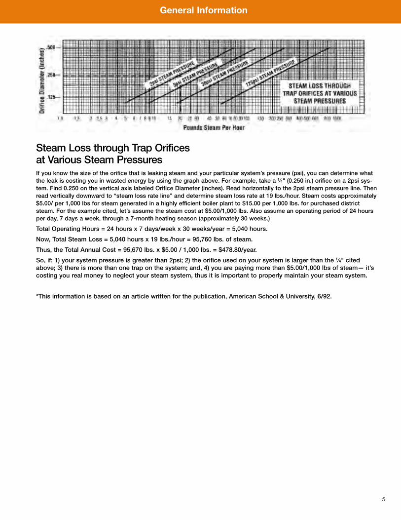
Steam Loss through Trap Orificesat Various Steam PressuresIf you know the size of the orifice that is leaking steam and your particular system’s pressure (psi), you can determine whatthe leak is costing you in wasted energy by using the graph above. For example, take a 1⁄4" (0.250 in.) orifice on a 2psi sys-tem. Find 0.250 on the vertical axis labeled Orifice Diameter (inches). Read horizontally to the 2psi steam pressure line. Thenread vertically downward to “steam loss rate line” and determine steam loss rate at 19 lbs./hour. Steam costs approximately$5.00/ per 1,000 lbs for steam generated in a highly efficient boiler plant to $15.00 per 1,000 lbs. for purchased districtsteam. For the example cited, let’s assume the steam cost at $5.00/1,000 lbs. Also assume an operating period of 24 hoursper day, 7 days a week, through a 7-month heating season (approximately 30 weeks.)
Total Operating Hours = 24 hours x 7 days/week x 30 weeks/year = 5,040 hours.
Now, Total Steam Loss = 5,040 hours x 19 lbs./hour = 95,760 lbs. of steam.
Thus, the Total Annual Cost = 95,670 lbs. x $5.00 / 1,000 lbs. = $478.80/year.
So, if: 1) your system pressure is greater than 2psi; 2) the orifice used on your system is larger than the 1⁄4" citedabove; 3) there is more than one trap on the system; and, 4) you are paying more than $5.00/1,000 lbs of steam— it’scosting you real money to neglect your steam system, thus it is important to properly maintain your steam system.
*This information is based on an article written for the publication, American School & University, 6/92.
Steam Traps
6
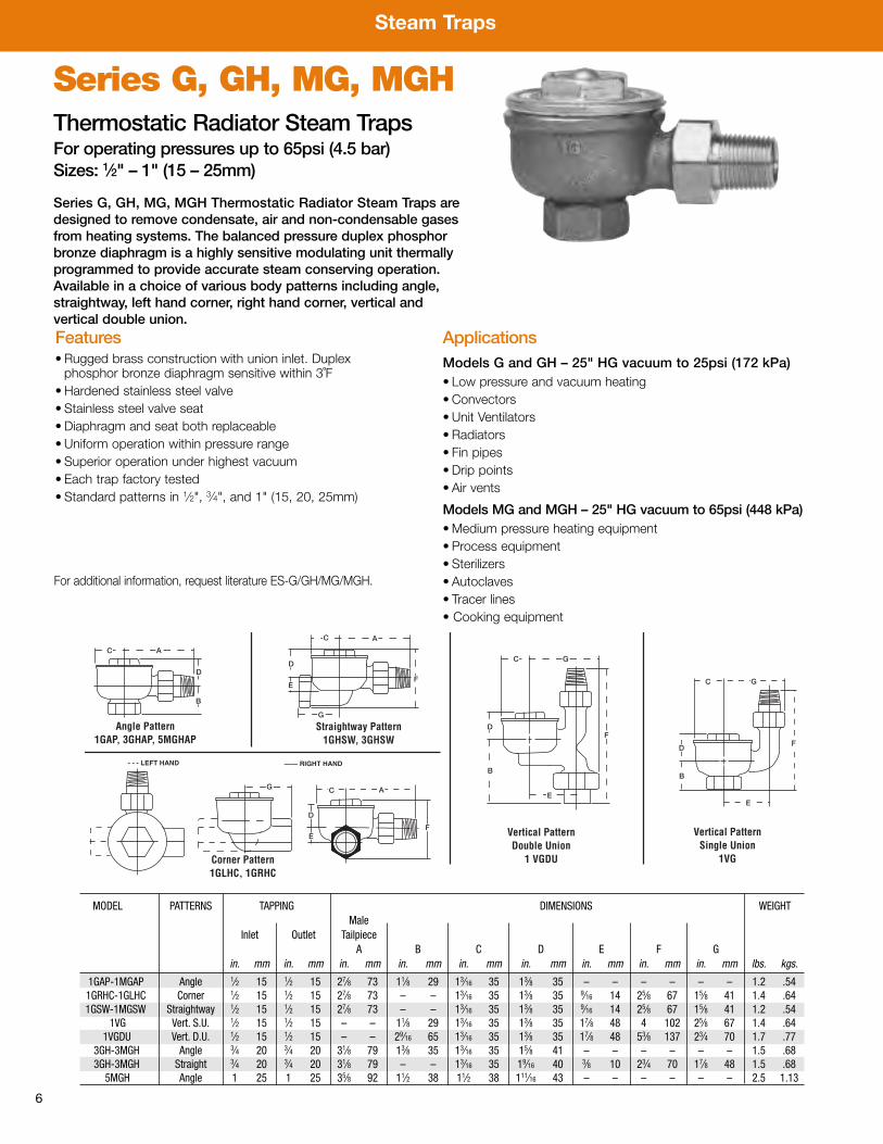
MODEL PATTERNS TAPPING DIMENSIONS WEIGHTMale
Inlet Outlet TailpieceA B C D E F G
in. mm in. mm in. mm in. mm in. mm in. mm in. mm in. mm in. mm lbs. kgs.
1GAP-1MGAP Angle 1⁄2 15 1⁄2 15 27⁄8 73 11⁄8 29 13⁄16 35 13⁄8 35 – – – – – – 1.2 .541GRHC-1GLHC Corner 1⁄2 15 1⁄2 15 27⁄8 73 – – 13⁄16 35 13⁄8 35 9⁄16 14 25⁄8 67 15⁄8 41 1.4 .641GSW-1MGSW Straightway 1⁄2 15 1⁄2 15 27⁄8 73 – – 13⁄16 35 13⁄8 35 9⁄16 14 25⁄8 67 15⁄8 41 1.2 .54
1VG Vert. S.U. 1⁄2 15 1⁄2 15 – – 11⁄8 29 13⁄16 35 13⁄8 35 17⁄8 48 4 102 25⁄8 67 1.4 .641VGDU Vert. D.U. 1⁄2 15 1⁄2 15 – – 29⁄16 65 13⁄16 35 13⁄8 35 17⁄8 48 53⁄8 137 23⁄4 70 1.7 .77
3GH-3MGH Angle 3⁄4 20 3⁄4 20 31⁄8 79 13⁄8 35 13⁄16 35 15⁄8 41 – – – – – – 1.5 .683GH-3MGH Straight 3⁄4 20 3⁄4 20 31⁄8 79 – – 13⁄16 35 19⁄16 40 3⁄8 10 23⁄4 70 17⁄8 48 1.5 .68
5MGH Angle 1 25 1 25 35⁄8 92 11⁄2 38 11⁄2 38 111⁄16 43 – – – – – – 2.5 1.13
C A
D
B
D
C
E
A
F
G
Angle Pattern1GAP, 3GHAP, 5MGHAP
Straightway Pattern1GHSW, 3GHSW
Corner Pattern1GLHC, 1GRHC
- - - LEFT HAND —— RIGHT HAND
Vertical PatternDouble Union
1 VGDU
Vertical PatternSingle Union
1VG
C G
F
B
D
D
B
E
F
C G
F
AC
D
E
GE
Series G, GH, MG, MGH Thermostatic Radiator Steam Traps aredesigned to remove condensate, air and non-condensable gasesfrom heating systems. The balanced pressure duplex phosphorbronze diaphragm is a highly sensitive modulating unit thermallyprogrammed to provide accurate steam conserving operation.Available in a choice of various body patterns including angle,straightway, left hand corner, right hand corner, vertical and vertical double union. Features• Rugged brass construction with union inlet. Duplex phosphor bronze diaphragm sensitive within 3˚F
• Hardened stainless steel valve• Stainless steel valve seat• Diaphragm and seat both replaceable• Uniform operation within pressure range• Superior operation under highest vacuum• Each trap factory tested• Standard patterns in 1⁄2", 3⁄4", and 1" (15, 20, 25mm)
ApplicationsModels G and GH – 25" HG vacuum to 25psi (172 kPa)• Low pressure and vacuum heating• Convectors• Unit Ventilators• Radiators• Fin pipes• Drip points• Air vents
Models MG and MGH – 25" HG vacuum to 65psi (448 kPa)•Medium pressure heating equipment• Process equipment• Sterilizers• Autoclaves• Tracer lines• Cooking equipment
Series G, GH, MG, MGHThermostatic Radiator Steam TrapsFor operating pressures up to 65psi (4.5 bar) Sizes: 1⁄2" – 1" (15 – 25mm)
For additional information, request literature ES-G/GH/MG/MGH.

Steam Traps
7
Series QFQuick-Fix™ Radiator Steam Trap Replacement Kits
Traps with Replaceable SeatsModel No. Manufacturer 1⁄2" Traps 3⁄4" Traps
QF-1 Warren Webster 02H, 02V, 502, 502V-1 503, 703, 713702, 702V-1, 712, 902V
QF-2 Warren Webster 512, 512H-1, 512G-1 513, 533523A, 523H-1**, 5236-1**
522, 522H, 522HB 713HB, 733, 733HB712HB, 722HB 723A
QF-3 Warren Webster 902HQF-4 Warren Webster 913A, 913HQF-5 Sarco E, H, S65, E, H, S65
TB25, TS25 TB25, TS25T65 T65Erwel R30Illinois 1G 3GHTrane B1*Marsh 1
Monash-Younker 30QF-6 Hoffman 17C 8CQF-14 Marsh 2-4, 2-7QF-15 Sterling 7-50AQF-16 Trane B3Dunham-Bush TH2A
Traps with Integral SeatsQF-7 Dunham-Bush 1B, 1C, 1R, V18
Trane B2Sarco T25
QF-8 Sarco T25Hoffman 8
QF-9 Illinois 1T, 2TQF-10 Barnes & Jones 122A, 122S, 3045QF-11 Barnes & Jones 134A, 134SQF-12 Trane B1*QF-13 Trane B3
Replacement Air Vents for F&T Traps (15 and 30psi)QF-25 Sarco Series FT 3⁄4" - 2"QF-26 Trane 686/55AL 3⁄4" - 1"
Replacement Thermal Capsule OnlyQFC-10 ALL ALL ALL
* Except vertical models** Old style omits “-1” from symbol. For traps built since 1931 only .
Series QF Quick-Fix™ Radiator Steam Trap Replacement Kits are used to repair oldor obsolete radiator steam traps without the cost of replacing the steam trap bodyor expensive repiping. The stainless steel capsule and valve seat are designed asoriginal equipment parts for many hard to find or obsolete radiator steam traps.
Remove the cover of the old steam trap and take out any remaining trap parts.Install the stainless steel Quick-Fix™ seat and snap the stainless steel capsule ontothe new seat. Replace the cover and the radiator steam trap has been repaired.
Contact Watts for any model radiator traps not listed below.
Quick, Easy installation
Once the Quick-Fix™ kits are installed, most subsequent trap repairs requireonly replacement of the capsule, which is the same for all trap kits.
1.
2.
3.
Remove cover of trap and old trap parts.
Install seat adapter, then snap capsule onto it.
Replace original cover.
For additional information, request literature ES-QF.
Steam Traps
8
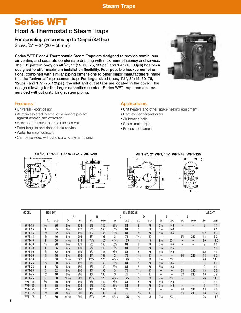
Series WFTFloat & Thermostatic Steam TrapsFor operating pressures up to 125psi (8.6 bar)Sizes: 3⁄4" – 2" (20 – 50mm)
MODEL SIZE (DN) DIMENSIONS WEIGHTA B C D E E1
in. mm in. mm in. mm in. mm in. mm in. mm in. mm lbs. kgs.
WFT-15 3⁄4 20 61⁄4 159 51⁄2 140 35⁄16 84 3 76 53⁄4 146 – – 9 4.1WFT-15 1 25 61⁄4 159 51⁄2 140 35⁄16 84 3 76 53⁄4 146 – – 9 4.1WFT-15 11⁄4 32 61⁄4 159 53⁄4 146 35⁄16 84 3 76 53⁄4 146 – – 9.5 4.3WFT-15 11⁄2 40 81⁄2 216 41⁄4 108 3 76 11⁄16 17 – – 83⁄8 213 18 8.2WFT-15 2 50 913⁄16 249 415⁄16 125 415⁄16 125 1⁄8 3 91⁄8 231 – – 26 11.8WFT-30 3⁄4 20 61⁄4 159 51⁄2 140 35⁄16 84 3 76 53⁄4 146 – – 9 4.1WFT-30 1 25 61⁄4 159 51⁄2 140 35⁄16 84 3 76 53⁄4 146 – – 9 4.1WFT-30 11⁄4 32 61⁄4 159 53⁄4 146 35⁄16 84 3 76 53⁄4 146 – - 9.5 4.3WFT-30 11⁄2 40 81⁄2 216 41⁄4 108 3 76 11⁄16 17 – – 83⁄8 213 18 8.2WFT-30 2 50 913⁄16 249 415⁄16 125 415⁄16 125 1⁄8 3 91⁄8 231 – – 26 11.8WFT-75 3⁄4 20 61⁄4 159 51⁄2 140 35⁄16 84 3 76 53⁄4 146 – – 9 4.1WFT-75 1 25 61⁄4 159 51⁄2 140 35⁄16 84 3 76 53⁄4 146 – – 9 4.1WFT-75 11⁄4 32 81⁄2 216 41⁄4 108 3 76 11⁄16 17 – – 83⁄8 213 18 8.2WFT-75 11⁄2 40 81⁄2 216 41⁄4 108 3 76 11⁄16 17 – – 83⁄8 213 18 8.2WFT-75 2 50 913⁄16 249 415⁄16 125 415⁄16 125 1⁄8 3 91⁄8 231 – – 26 11.8WFT-125 3⁄4 20 61⁄4 159 51⁄2 140 35⁄16 84 3 76 53⁄4 146 – – 9 4.1WFT-125 1 25 61⁄4 159 51⁄2 140 35⁄16 84 3 76 53⁄4 146 – – 9 4.1WFT-125 11⁄4 32 81⁄2 216 41⁄4 108 3 76 11⁄16 17 – – 83⁄8 213 18 8.2WFT-125 11⁄2 40 81⁄2 216 41⁄4 108 3 76 11⁄16 17 – – 83⁄8 213 18 8.2WFT-125 2 50 913⁄16 249 415⁄16 125 415⁄16 125 1⁄8 3 91⁄8 231 – – 26 11.8
Series WFT Float & Thermostatic Steam Traps are designed to provide continuousair venting and separate condensate draining with maximum efficiency and service.The “H” pattern body on all 3⁄4", 1" (15, 30, 75, 125psi) and 11⁄4" (15, 30psi) has beendesigned to offer maximum installation flexibility. Four possible hookup combina-tions, combined with similar piping dimensions to other major manufacturers, makethis the “universal” replacement trap. For larger sized traps, 11⁄2", 2" (15, 30, 75,125psi) and 11⁄4" (75, 125psi), the inlet and outlet taps are located in the cover. Thisdesign allowing for the larger capacities needed. Series WFT traps can also beserviced without disturbing system piping.
Features:• Universal 4-port design• All stainless steel internal components protect against erosion and corrosion
• Balanced pressure thermostatic element• Extra-long life and dependable service•Water hammer resistant• Can be serviced without disturbing system piping
Applications:• Unit heaters and other space heating equipment• Heat exchangers/reboilers• Air heating coils• Steam main drips• Process equipment
A
EC
A
E
E1 C
B
D
B
D
All 3⁄4", 1" WFT, 11⁄4" WFT–15, WFT–30 All 11⁄2", 2" WFT, 11⁄4" WFT-75, WFT-125
Steam Traps
9
Size DIFFERENTIAL PRESSURE (psi)NPT PSIG
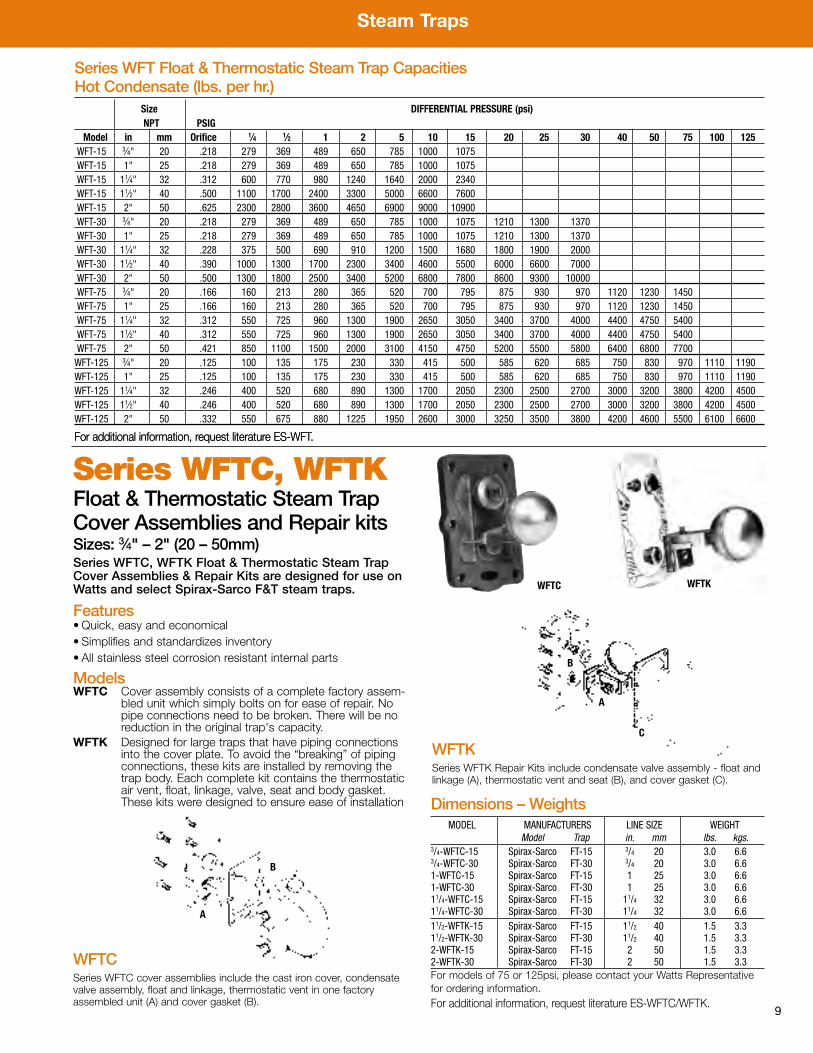
Model in mm Orifice 1⁄4 1⁄2 1 2 5 10 15 20 25 30 40 50 75 100 125WFT-15 3⁄4" 20 .218 279 369 489 650 785 1000 1075WFT-15 1" 25 .218 279 369 489 650 785 1000 1075WFT-15 11⁄4" 32 .312 600 770 980 1240 1640 2000 2340WFT-15 11⁄2" 40 .500 1100 1700 2400 3300 5000 6600 7600WFT-15 2" 50 .625 2300 2800 3600 4650 6900 9000 10900WFT-30 3⁄4" 20 .218 279 369 489 650 785 1000 1075 1210 1300 1370WFT-30 1" 25 .218 279 369 489 650 785 1000 1075 1210 1300 1370WFT-30 11⁄4" 32 .228 375 500 690 910 1200 1500 1680 1800 1900 2000WFT-30 11⁄2" 40 .390 1000 1300 1700 2300 3400 4600 5500 6000 6600 7000WFT-30 2" 50 .500 1300 1800 2500 3400 5200 6800 7800 8600 9300 10000WFT-75 3⁄4" 20 .166 160 213 280 365 520 700 795 875 930 970 1120 1230 1450WFT-75 1" 25 .166 160 213 280 365 520 700 795 875 930 970 1120 1230 1450WFT-75 11⁄4" 32 .312 550 725 960 1300 1900 2650 3050 3400 3700 4000 4400 4750 5400WFT-75 11⁄2" 40 .312 550 725 960 1300 1900 2650 3050 3400 3700 4000 4400 4750 5400WFT-75 2" 50 .421 850 1100 1500 2000 3100 4150 4750 5200 5500 5800 6400 6800 7700WFT-125 3⁄4" 20 .125 100 135 175 230 330 415 500 585 620 685 750 830 970 1110 1190WFT-125 1" 25 .125 100 135 175 230 330 415 500 585 620 685 750 830 970 1110 1190WFT-125 11⁄4" 32 .246 400 520 680 890 1300 1700 2050 2300 2500 2700 3000 3200 3800 4200 4500WFT-125 11⁄2" 40 .246 400 520 680 890 1300 1700 2050 2300 2500 2700 3000 3200 3800 4200 4500WFT-125 2" 50 .332 550 675 880 1225 1950 2600 3000 3250 3500 3800 4200 4600 5500 6100 6600
Series WFT Float & Thermostatic Steam Trap CapacitiesHot Condensate (lbs. per hr.)
For additional information, request literature ES-WFT.For additional information, request literature ES-WFT.
WFTCSeries WFTC cover assemblies include the cast iron cover, condensatevalve assembly, float and linkage, thermostatic vent in one factoryassembled unit (A) and cover gasket (B).
A
B
WFTC WFTK
Series WFTC, WFTKFloat & Thermostatic Steam TrapCover Assemblies and Repair kitsSizes: 3⁄4" – 2" (20 – 50mm)Series WFTC, WFTK Float & Thermostatic Steam TrapCover Assemblies & Repair Kits are designed for use onWatts and select Spirax-Sarco F&T steam traps.
Features• Quick, easy and economical• Simplifies and standardizes inventory• All stainless steel corrosion resistant internal parts
ModelsWFTC Cover assembly consists of a complete factory assem-
bled unit which simply bolts on for ease of repair. Nopipe connections need to be broken. There will be noreduction in the original trap's capacity.
WFTK Designed for large traps that have piping connectionsinto the cover plate. To avoid the “breaking” of pipingconnections, these kits are installed by removing thetrap body. Each complete kit contains the thermostaticair vent, float, linkage, valve, seat and body gasket.These kits were designed to ensure ease of installation
WFTKSeries WFTK Repair Kits include condensate valve assembly - float andlinkage (A), thermostatic vent and seat (B), and cover gasket (C).
A
B
C
Dimensions – WeightsMODEL MANUFACTURERS LINE SIZE WEIGHT
Model Trap in. mm lbs. kgs.3/4-WFTC-15 Spirax-Sarco FT-15 3/4 20 3.0 6.63/4-WFTC-30 Spirax-Sarco FT-30 3/4 20 3.0 6.61-WFTC-15 Spirax-Sarco FT-15 1 25 3.0 6.61-WFTC-30 Spirax-Sarco FT-30 1 25 3.0 6.611/4-WFTC-15 Spirax-Sarco FT-15 11/4 32 3.0 6.611/4-WFTC-30 Spirax-Sarco FT-30 11/4 32 3.0 6.611/2-WFTK-15 Spirax-Sarco FT-15 11/2 40 1.5 3.311/2-WFTK-30 Spirax-Sarco FT-30 11/2 40 1.5 3.32-WFTK-15 Spirax-Sarco FT-15 2 50 1.5 3.32-WFTK-30 Spirax-Sarco FT-30 2 50 1.5 3.3For models of 75 or 125psi, please contact your Watts Representativefor ordering information.For additional information, request literature ES-WFTC/WFTK.

Steam Traps
10
Series G, MGFloat & Thermostatic Steam TrapsFor operating pressures up to 50psi (345 kPa)Sizes: 3⁄4" – 2" (20 – 50mm)
Features• Fail safe – In case of float failure, trap will dischargecondensate and air; no unit freeze-up
• Air vent parts – accessible without disturbing piping• Inlet baffle – breaks up water hammer; preventsdamage to parts
• Snap action valve – no wire-drawing or valve chatter• Two moving parts – no levers, hinges or pins to corrodeor jam
• Straight-through connections – saves installation time,labor, space, headroom
• Stainless valves and valve seats• Seamless copper float – no seams to develop leaks• Uniform operations – not affected by changes in loador pressures
• Condensate valve rotates – ensures even wear, longervalve and seat life
Applications• Steam coils• Unit heaters• Drip points• Heat exchangers•Water heaters• Absorption machines• Unit ventilators• Air handlers• Make-up air coils• Re-heat coils• Jacketed kettles
A
F
INLET
OUTLET
D
C
B
Series G, MG Float & Thermostatic Steam Traps are designed for use on modulatingprocess equipment and as main distribution line drip traps. Series G Float &Thermostatic steam traps feature a straight through design for fast simple installation.Stainless steel valve head and seats provide long service life.
G, MG series steam traps have excellent air venting capability and discharge conden-sate at near to steam temperature so the steam space remains free of condensate pro-viding improved steam system efficiency.
MODEL TAPPING (NPT) DIMENSIONS WEIGHTA B C D F
in. mm in. mm in. mm in. mm in. mm n. mm lbs. kgs.
6G-15 3⁄4 20 41⁄2 114 61⁄2 165 41⁄2 114 415⁄16 125 17⁄8 48 6 1527G-15 1 25 51⁄2 140 71⁄2 191 51⁄2 140 55⁄8 143 21⁄16 52 9 2298G-15 11⁄4 32 51⁄2 140 8 203 6 152 51⁄2 140 2 51 12 30591G-15 11⁄2 40 75⁄8 194 113⁄4 298 89⁄16 217 91⁄16 230 23⁄16 71 39 991
101G-15 2 50 95⁄16 237 1313⁄16 351 103⁄8 263 1015⁄16 278 23⁄8 60 59 1499111G-15 2 50 103⁄8 264 151⁄4 387 115⁄8 295 117⁄8 302 23⁄4 70 85 21597MG-30 1 25 51⁄2 140 71⁄2 191 51⁄2 140 55⁄8 143 21⁄16 52 9 2298MG-30 11⁄4 32 51⁄2 140 8 203 6 152 51⁄2 140 2 51 12 305
91MG-30 11⁄2 40 75⁄8 194 113⁄4 298 89⁄16 217 91⁄16 230 23⁄16 71 39 991101MG-30 2 50 95⁄16 237 1313⁄16 351 103⁄8 263 1015⁄16 278 23⁄8 60 59 1499111MG-30 2 50 103⁄8 264 151⁄4 387 115⁄8 295 117⁄8 302 23⁄4 70 85 2159
6MG-50 3⁄4 20 41⁄2 114 61⁄2 165 41⁄2 114 415⁄16 125 17⁄8 48 6 1527MG-50 1 25 51⁄2 140 71⁄2 191 51⁄2 140 55⁄8 143 21⁄16 52 9 2298MG-50 11⁄4 32 51⁄2 140 8 203 6 152 51⁄2 140 2 51 12 305
91MG-50 11⁄2 40 75⁄8 194 113⁄4 298 89⁄16 217 91⁄16 230 23⁄16 71 39 991101MG-50 2 50 95⁄16 237 1313⁄16 351 103⁄8 263 1015⁄16 278 23⁄8 60 59 1499111MG-50 2 50 103⁄8 264 151⁄4 387 115⁄8 295 117⁄8 302 23⁄4 70 85 2159
ModelsG-15 — 25" Hg to 15psi (103 kPa)MG-30 — 25" Hg to 30psi (207 kPa)MG-50 — 25" Hg to 50psi (345 kPa)
Steam Traps
11
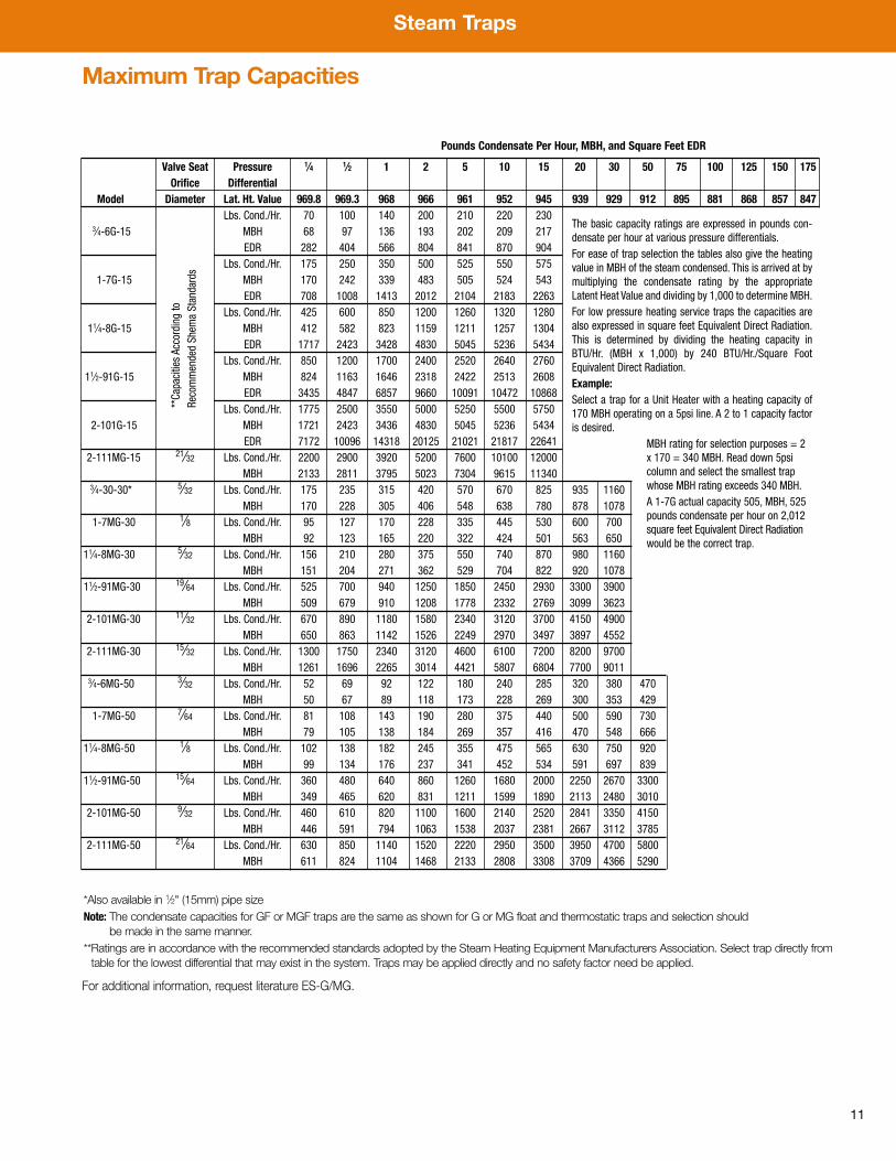
Valve Seat Pressure 1⁄4 1⁄2 1 2 5 10 15 20 30 50 75 100 125 150 175Orifice Differential
Model Diameter Lat. Ht. Value 969.8 969.3 968 966 961 952 945 939 929 912 895 881 868 857 847Lbs. Cond./Hr. 70 100 140 200 210 220 230
3⁄4-6G-15 MBH 68 97 136 193 202 209 217EDR 282 404 566 804 841 870 904
Lbs. Cond./Hr. 175 250 350 500 525 550 5751-7G-15 MBH 170 242 339 483 505 524 543
EDR 708 1008 1413 2012 2104 2183 2263Lbs. Cond./Hr. 425 600 850 1200 1260 1320 1280
11⁄4-8G-15 MBH 412 582 823 1159 1211 1257 1304EDR 1717 2423 3428 4830 5045 5236 5434
Lbs. Cond./Hr. 850 1200 1700 2400 2520 2640 276011⁄2-91G-15 MBH 824 1163 1646 2318 2422 2513 2608
EDR 3435 4847 6857 9660 10091 10472 10868Lbs. Cond./Hr. 1775 2500 3550 5000 5250 5500 5750
2-101G-15 MBH 1721 2423 3436 4830 5045 5236 5434EDR 7172 10096 14318 20125 21021 21817 22641
2-111MG-15 21⁄32 Lbs. Cond./Hr. 2200 2900 3920 5200 7600 10100 12000MBH 2133 2811 3795 5023 7304 9615 11340
3⁄4-30-30* 5⁄32 Lbs. Cond./Hr. 175 235 315 420 570 670 825 935 1160MBH 170 228 305 406 548 638 780 878 1078
1-7MG-30 1⁄8 Lbs. Cond./Hr. 95 127 170 228 335 445 530 600 700MBH 92 123 165 220 322 424 501 563 650
11⁄4-8MG-30 5⁄32 Lbs. Cond./Hr. 156 210 280 375 550 740 870 980 1160MBH 151 204 271 362 529 704 822 920 1078
11⁄2-91MG-30 19⁄64 Lbs. Cond./Hr. 525 700 940 1250 1850 2450 2930 3300 3900MBH 509 679 910 1208 1778 2332 2769 3099 3623
2-101MG-30 11⁄32 Lbs. Cond./Hr. 670 890 1180 1580 2340 3120 3700 4150 4900MBH 650 863 1142 1526 2249 2970 3497 3897 4552
2-111MG-30 15⁄32 Lbs. Cond./Hr. 1300 1750 2340 3120 4600 6100 7200 8200 9700MBH 1261 1696 2265 3014 4421 5807 6804 7700 9011
3⁄4-6MG-50 3⁄32 Lbs. Cond./Hr. 52 69 92 122 180 240 285 320 380 470MBH 50 67 89 118 173 228 269 300 353 429
1-7MG-50 7⁄64 Lbs. Cond./Hr. 81 108 143 190 280 375 440 500 590 730MBH 79 105 138 184 269 357 416 470 548 666
11⁄4-8MG-50 1⁄8 Lbs. Cond./Hr. 102 138 182 245 355 475 565 630 750 920MBH 99 134 176 237 341 452 534 591 697 839
11⁄2-91MG-50 15⁄64 Lbs. Cond./Hr. 360 480 640 860 1260 1680 2000 2250 2670 3300MBH 349 465 620 831 1211 1599 1890 2113 2480 3010
2-101MG-50 9⁄32 Lbs. Cond./Hr. 460 610 820 1100 1600 2140 2520 2841 3350 4150MBH 446 591 794 1063 1538 2037 2381 2667 3112 3785
2-111MG-50 21⁄64 Lbs. Cond./Hr. 630 850 1140 1520 2220 2950 3500 3950 4700 5800MBH 611 824 1104 1468 2133 2808 3308 3709 4366 5290
The basic capacity ratings are expressed in pounds con-densate per hour at various pressure differentials.For ease of trap selection the tables also give the heatingvalue in MBH of the steam condensed. This is arrived at bymultiplying the condensate rating by the appropriateLatent Heat Value and dividing by 1,000 to determine MBH.For low pressure heating service traps the capacities arealso expressed in square feet Equivalent Direct Radiation.This is determined by dividing the heating capacity inBTU/Hr. (MBH x 1,000) by 240 BTU/Hr./Square FootEquivalent Direct Radiation.Example:Select a trap for a Unit Heater with a heating capacity of170 MBH operating on a 5psi line. A 2 to 1 capacity factoris desired.
MBH rating for selection purposes = 2 x 170 = 340 MBH. Read down 5psi column and select the smallest trap whose MBH rating exceeds 340 MBH.A 1-7G actual capacity 505, MBH, 525 pounds condensate per hour on 2,012 square feet Equivalent Direct Radiationwould be the correct trap.
*Also available in 1⁄2" (15mm) pipe sizeNote: The condensate capacities for GF or MGF traps are the same as shown for G or MG float and thermostatic traps and selection should
be made in the same manner.**Ratings are in accordance with the recommended standards adopted by the Steam Heating Equipment Manufacturers Association. Select trap directly fromtable for the lowest differential that may exist in the system. Traps may be applied directly and no safety factor need be applied.
**Capacities According to
Recommended Shem
a Standards
Maximum Trap Capacities
Pounds Condensate Per Hour, MBH, and Square Feet EDR
For additional information, request literature ES-G/MG.

Steam Traps
12
Series WIBInverted Bucket Steam TrapsFor operating pressures up to 250psi (17 bar)Sizes: 1⁄2" – 1" (15 – 25mm)
SIZE (DN) DIMENSIONS WEIGHTNPT A B C
in. mm in. mm in. mm in. mm lbs. kgs.
WIB 801⁄2 15 5 127 81⁄8 206 31⁄4 83 5.5 2.53⁄4 20 5 127 81⁄8 206 31⁄4 83 5.5 2.5WIB 811⁄2 15 5 127 75⁄8 194 31⁄4 83 6 2.73⁄4 20 5 127 75⁄8 194 31⁄4 83 6 2.71 25 5 127 75⁄8 194 31⁄4 83 6 2.7
B
C
A
Series WIB Inverted Bucket Steam Traps are designed for reliable condensateremoval on steam main line drips for system pressure up to 250psi. Series WIBInverted Bucket Traps have an excellent reputation as a long lasting, rugged steamtrap, naturally resistant to water hammer.
WIB 80
WIB 81
Features• In-line connections• Hardened stainless steel valve and seat• Cast iron body construction; Class 250• Stainless steel bucket• Test plug• Drain plug
ModelsWIB 80 – 1⁄2" – 3⁄4" (15–20mm) for operating pressures up to
150psi (10 bar)
WIB 81 – 1⁄2" – 1" (15–25mm) for operating pressures up to250psi (17 bar)
Pressure — TemperatureWIB 80
Maximum Allowable Pressure: 150psi (10 bar)Maximum Allowable Temperature: 406°F (208°C)Maximum Operating Pressure: 150psi (10 bar)
WIB 81
Maximum Allowable Pressure: 250psi (17 bar)Maximum Allowable Temperature: 406°F (208°C)Maximum Operating Pressure: 250psi (17 bar)
Applications• Steam main drips• Process applications requiring minimal air venting
Steam Traps
13
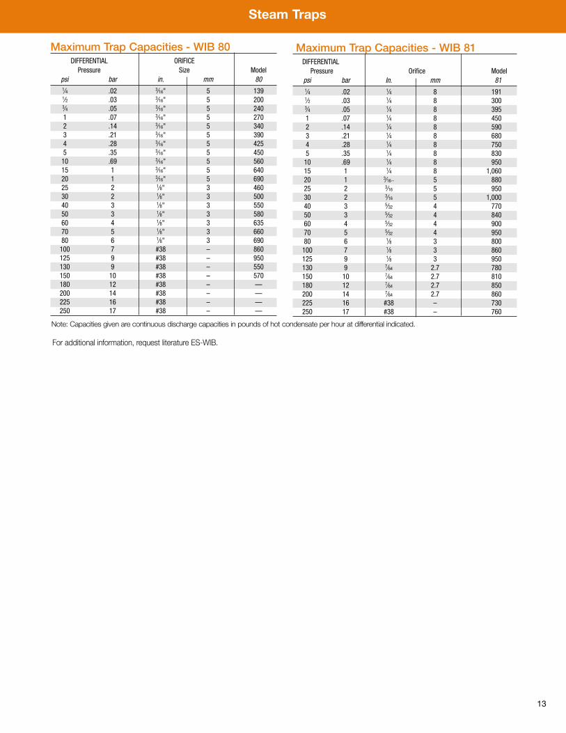
Maximum Trap Capacities - WIB 81DIFFERENTIAL
Pressure Orifice Modelpsi bar In. mm 811⁄4 .02 1⁄4 8 1911⁄2 .03 1⁄4 8 3003⁄4 .05 1⁄4 8 3951 .07 1⁄4 8 4502 .14 1⁄4 8 5903 .21 1⁄4 8 6804 .28 1⁄4 8 7505 .35 1⁄4 8 83010 .69 1⁄4 8 95015 1 1⁄4 8 1,06020 1 3⁄16-- 5 88025 2 3⁄16 5 95030 2 3⁄16 5 1,00040 3 5⁄32 4 77050 3 5⁄32 4 84060 4 5⁄32 4 90070 5 5⁄32 4 95080 6 1⁄8 3 800100 7 1⁄8 3 860125 9 1⁄8 3 950130 9 7⁄64 2.7 780150 10 7⁄64 2.7 810180 12 7⁄64 2.7 850200 14 7⁄64 2.7 860225 16 #38 – 730250 17 #38 – 760
Maximum Trap Capacities - WIB 80DIFFERENTIAL ORIFICE
Pressure Size Modelpsi bar in. mm 801⁄4 .02 3⁄16" 5 1391⁄2 .03 3⁄16" 5 2003⁄4 .05 3⁄16" 5 2401 .07 3⁄16" 5 2702 .14 3⁄16" 5 3403 .21 3⁄16" 5 3904 .28 3⁄16" 5 4255 .35 3⁄16" 5 45010 .69 3⁄16" 5 56015 1 3⁄16" 5 64020 1 3⁄16" 5 69025 2 1⁄8" 3 46030 2 1⁄8" 3 50040 3 1⁄8" 3 55050 3 1⁄8" 3 58060 4 1⁄8" 3 63570 5 1⁄8" 3 66080 6 1⁄8" 3 690100 7 #38 – 860125 9 #38 – 950130 9 #38 – 550150 10 #38 – 570180 12 #38 – —200 14 #38 – —225 16 #38 – —250 17 #38 – —
Note: Capacities given are continuous discharge capacities in pounds of hot condensate per hour at differential indicated.
For additional information, request literature ES-WIB.

Steam Traps
14
Series WTD 600Thermodynamic Steam TrapsFor operating pressures up to 600psi (41 bar)Sizes: 3⁄8" – 1" (10 – 25mm)
Features• Inexpensive: low initial purchase price and lower maintenancecosts than traps requiring expensive repair kits
• Compact design; light weight and easy to install. Provideslonger service life with simple maintainability. The only movingpart is the hardened stainless steel disc
• Rugged all stainless steel: resistant to water hammer, freezing,superheat and corrosion for extra long service life
• Audible discharge cycle: checking trap operation is simple anddoes not require any special devices
• Blast discharge of condensate: eliminates dirt build up andprovides a tight shutoff, saving valuable steam energy
Applications• Steam main drainage• Superheat steam applications• Steam tracing lines• Freeze protection for outside applications• Small process equipment
Pressure – TemperatureMaximum Operating Pressure: 600psi (42 bar)
Maximum Operating Temperature: 800°F (427°C)
Maximum Allowable Pressure: 600psi (42 bar)
Maximum Allowable Temperature: 800°F (427°C)
SIZE (DN) DIMENSIONS WEIGHTA B C
in. mm in. mm in. mm in. mm lbs. kg.3⁄8 10 2 51 13⁄4 45 13⁄4 45 .8 .361⁄2 15 211⁄16 68 13⁄4 45 2" 51 1.2 .543⁄4 20 213⁄16 71 25⁄16 59 27⁄16 62 1.8 .821 25 35⁄16 84 21⁄2 64 27⁄8 73 3.1 1.41
C
A
B
Series WTD 600 Thermodynamic Steam Traps are economical and compact,designed to efficiently drain steam mains, steam tracing lines, and small processequipment. The WTD 600 Steam Trap discharges condensate at near to steamtemperatures, so the steam space remains free of condensate. Their tight shut-off feature ensures that valuable steam energy is not wasted. The WTD 600's hard-ened disc is the only moving part, assuring a long service life, easy low cost main-tainability, and improved steam system efficiency.
Maximum Capacity – Lbs./Hr. at Saturation Steam TemperatureNPT PSIG (BAR)
CONNECTION 3.5 5 10 20 30 50 75 100 150 200 300 400 500 600in. mm (0.24) (0.34) (0.7) (1.4) (2.1) (3.4) (5.2) (6.9) (10.3) (13.8) (20.7) (27.6) (34.5) (41.8)3⁄8" 10 180 185 190 200 215 245 305 370 500 610 790 960 1100 12501⁄2" 15 300 310 345 410 465 575 700 810 1000 1140 1410 1630 1830 20003⁄4" 20 405 420 470 550 640 810 1000 1160 1450 1670 2100 2430 2750 30501" 25 640 670 725 865 980 1200 1470 1750 2200 2600 3250 3780 4250 4700
For Kg./Hr. multiply by .454
For additional information, request literature ES-WTD.
Steam Safety Relief Valve
15
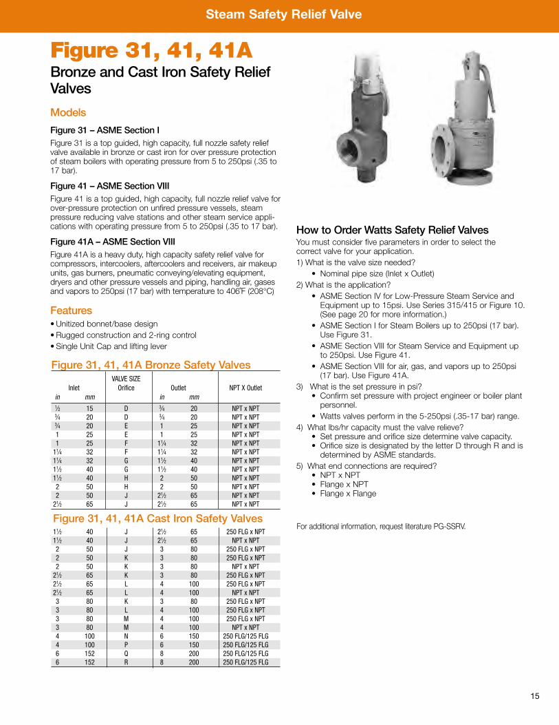
Figure 31, 41, 41ABronze and Cast Iron Safety ReliefValves
Models
Figure 31 – ASME Section IFigure 31 is a top guided, high capacity, full nozzle safety reliefvalve available in bronze or cast iron for over pressure protectionof steam boilers with operating pressure from 5 to 250psi (.35 to17 bar).
Figure 41 – ASME Section VIIIFigure 41 is a top guided, high capacity, full nozzle relief valve forover-pressure protection on unfired pressure vessels, steampressure reducing valve stations and other steam service appli-cations with operating pressure from 5 to 250psi (.35 to 17 bar).
Figure 41A – ASME Section VIIIFigure 41A is a heavy duty, high capacity safety relief valve forcompressors, intercoolers, aftercoolers and receivers, air makeupunits, gas burners, pneumatic conveying/elevating equipment,dryers and other pressure vessels and piping, handling air, gasesand vapors to 250psi (17 bar) with temperature to 406˚F (208°C)
Features• Unitized bonnet/base design• Rugged construction and 2-ring control• Single Unit Cap and lifting lever
Figure 31, 41, 41A Bronze Safety ValvesVALVE SIZE
Inlet Orifice Outlet NPT X Outletin mm in mm1⁄2 15 D 3⁄4 20 NPT x NPT3⁄4 20 D 3⁄4 20 NPT x NPT3⁄4 20 E 1 25 NPT x NPT1 25 E 1 25 NPT x NPT1 25 F 11⁄4 32 NPT x NPT11⁄4 32 F 11⁄4 32 NPT x NPT11⁄4 32 G 11⁄2 40 NPT x NPT11⁄2 40 G 11⁄2 40 NPT x NPT11⁄2 40 H 2 50 NPT x NPT2 50 H 2 50 NPT x NPT2 50 J 21⁄2 65 NPT x NPT21⁄2 65 J 21⁄2 65 NPT x NPT
Figure 31, 41, 41A Cast Iron Safety Valves11⁄2 40 J 21⁄2 65 250 FLG x NPT11⁄2 40 J 21⁄2 65 NPT x NPT2 50 J 3 80 250 FLG x NPT2 50 K 3 80 250 FLG x NPT2 50 K 3 80 NPT x NPT21⁄2 65 K 3 80 250 FLG x NPT21⁄2 65 L 4 100 250 FLG x NPT21⁄2 65 L 4 100 NPT x NPT3 80 K 3 80 250 FLG x NPT3 80 L 4 100 250 FLG x NPT3 80 M 4 100 250 FLG x NPT3 80 M 4 100 NPT x NPT4 100 N 6 150 250 FLG/125 FLG4 100 P 6 150 250 FLG/125 FLG6 152 Q 8 200 250 FLG/125 FLG6 152 R 8 200 250 FLG/125 FLG
For additional information, request literature PG-SSRV.
How to Order Watts Safety Relief ValvesYou must consider five parameters in order to select the correct valve for your application.1) What is the valve size needed?
• Nominal pipe size (Inlet x Outlet)2) What is the application?
• ASME Section IV for Low-Pressure Steam Service andEquipment up to 15psi. Use Series 315/415 or Figure 10.(See page 20 for more information.)
• ASME Section I for Steam Boilers up to 250psi (17 bar).Use Figure 31.
• ASME Section VIII for Steam Service and Equipment upto 250psi. Use Figure 41.
• ASME Section VIII for air, gas, and vapors up to 250psi(17 bar). Use Figure 41A.
3) What is the set pressure in psi?• Confirm set pressure with project engineer or boiler plantpersonnel.
• Watts valves perform in the 5-250psi (.35-17 bar) range.4) What lbs/hr capacity must the valve relieve?
• Set pressure and orifice size determine valve capacity.• Orifice size is designated by the letter D through R and isdetermined by ASME standards.
5) What end connections are required?• NPT x NPT• Flange x NPT• Flange x Flange
Steam Safety Relief Valve
16
B
E
D
Series 315, 415 ASME Section IV Rated Steam Safety Relief Valves have been devel-oped to provide high quality dependable low cost protection for any low pressuresteam heating equipment operating up to 15psi (103 kPa). This series features abronze body and stainless steel spring. A top guided stem and a non-shock Teflon®
disc-to-metal seat ensures positive shutoff.
MODEL SIZE ASME STEAM DIMENSIONS WEIGHTDischarge Capacity B D E
in. mm lbs./hr. @ 15psi in. mm in. mm in. mm lbs. kg.
315-M1 3⁄4 x 3⁄4 20 x 20 375 211⁄16 68 13⁄8 35 11⁄4 32 .55 .24415-M1 3⁄4 x 3⁄4 20 x 20 450 213⁄16 71 15⁄16 33 11⁄4 32 .70 .31415-M1 1 x 1 25 x 25 643 31⁄8 78 111⁄16 43 15⁄8 41 .91 .41415 11⁄4 x 11⁄2 32 x 40 1230 43⁄4 121 23⁄8 60 21⁄8 54 2.00 .91415 11⁄2 x 2 40 x 50 1860 57⁄16 138 25⁄8 67 25⁄16 59 3.00 1.36
Series 315 & 415Steam Safety ValvesFor steam heating boilers with operating pressures up to 15psi (103 kPa)
Features• High capacity• Positive shut off• Non-sticking Teflon® disc• Seat located above drain• NPT threaded male inlet x threaded femaleoutlet (drain) connection
ModelsL – Low pressure settingSC – Satin chrome finish
For additional information, request literature ES-315 or ES-415.
Steam Process Regulators
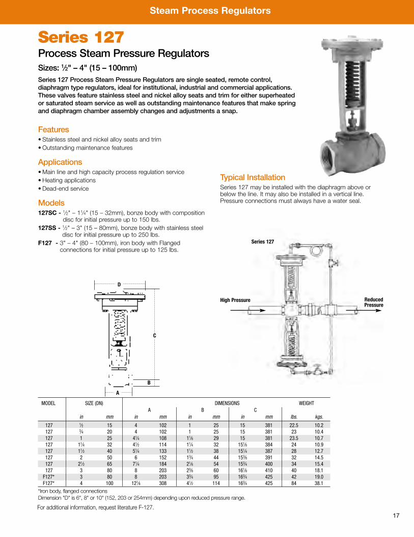
17
Features• Stainless steel and nickel alloy seats and trim• Outstanding maintenance features
Applications•Main line and high capacity process regulation service• Heating applications• Dead-end service
Models127SC - 1⁄2" – 11⁄4" (15 – 32mm), bonze body with composition
disc for initial pressure up to 150 lbs.127SS - 1⁄2" – 3" (15 – 80mm), bonze body with stainless steel
disc for initial pressure up to 250 lbs.F127 - 3" – 4" (80 – 100mm), iron body with Flanged
connections for initial pressure up to 125 lbs.
Typical InstallationSeries 127 may be installed with the diaphragm above orbelow the line. It may also be installed in a vertical line.Pressure connections must always have a water seal.
Series 127 Process Steam Pressure RegulatorsSizes: 1⁄2" – 4" (15 – 100mm)Series 127 Process Steam Pressure Regulators are single seated, remote control,diaphragm type regulators, ideal for institutional, industrial and commercial applications.These valves feature stainless steel and nickel alloy seats and trim for either superheatedor saturated steam service as well as outstanding maintenance features that make springand diaphragm chamber assembly changes and adjustments a snap.
MODEL SIZE (DN) DIMENSIONS WEIGHTA B C
in mm in mm in mm in mm lbs. kgs.
127 1⁄2 15 4 102 1 25 15 381 22.5 10.2127 3⁄4 20 4 102 1 25 15 381 23 10.4127 1 25 41⁄4 108 11⁄8 29 15 381 23.5 10.7127 11⁄4 32 41⁄2 114 11⁄4 32 151⁄8 384 24 10.9127 11⁄2 40 51⁄4 133 11⁄2 38 151⁄4 387 28 12.7127 2 50 6 152 13⁄4 44 153⁄8 391 32 14.5127 21⁄2 65 71⁄4 184 21⁄8 54 153⁄4 400 34 15.4127 3 80 8 203 23⁄8 60 161⁄8 410 40 18.1F127* 3 80 8 203 33⁄4 95 163⁄4 425 42 19.0F127* 4 100 121⁄8 308 41⁄2 114 163⁄4 425 84 38.1
*Iron body, flanged connectionsDimension "D" is 6", 8" or 10" (152, 203 or 254mm) depending upon reduced pressure range.
Series 127
ReducedPressure
High Pressure
C
B
D
A
For additional information, request literature F-127.
Steam Process Regulators
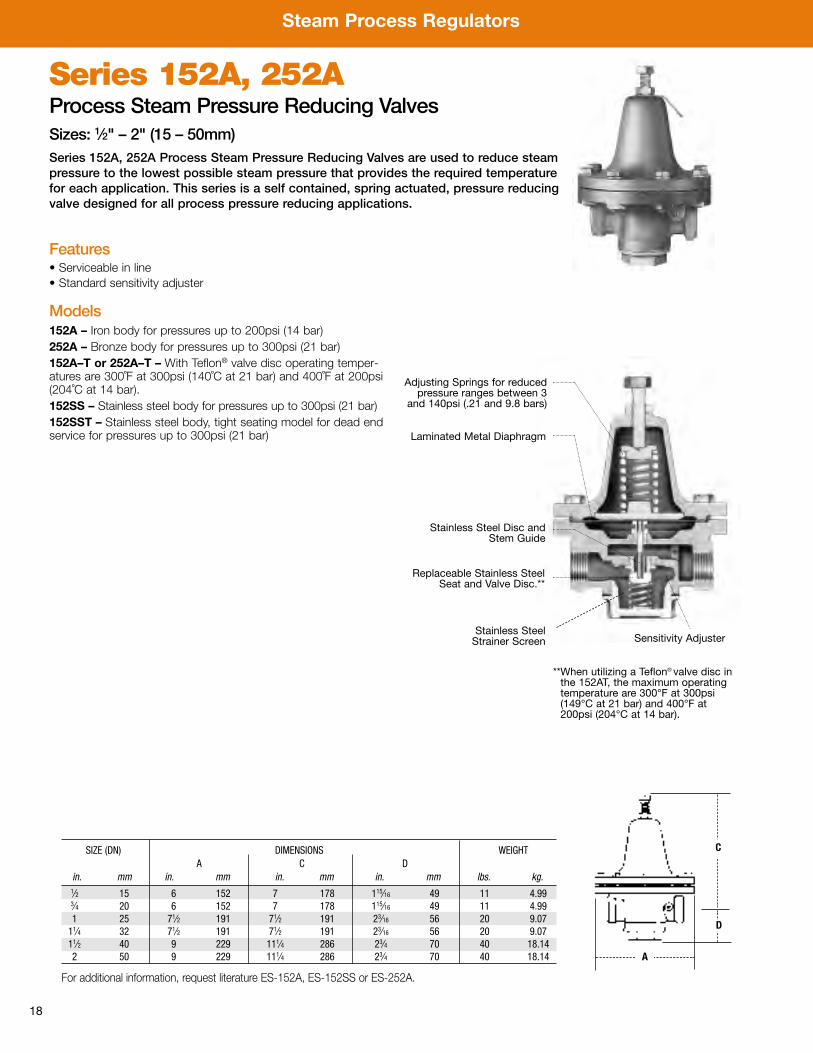
18
Series 152A, 252AProcess Steam Pressure Reducing ValvesSizes: 1⁄2" – 2" (15 – 50mm)Series 152A, 252A Process Steam Pressure Reducing Valves are used to reduce steampressure to the lowest possible steam pressure that provides the required temperaturefor each application. This series is a self contained, spring actuated, pressure reducingvalve designed for all process pressure reducing applications.
Features• Serviceable in line• Standard sensitivity adjuster
Models152A – Iron body for pressures up to 200psi (14 bar)252A – Bronze body for pressures up to 300psi (21 bar)152A–T or 252A–T – With Teflon® valve disc operating temper-atures are 300˚F at 300psi (140˚C at 21 bar) and 400˚F at 200psi(204˚C at 14 bar).152SS – Stainless steel body for pressures up to 300psi (21 bar)152SST – Stainless steel body, tight seating model for dead endservice for pressures up to 300psi (21 bar)
A
C
D
Adjusting Springs for reducedpressure ranges between 3
and 140psi (.21 and 9.8 bars)
Laminated Metal Diaphragm
Stainless Steel Disc andStem Guide
Replaceable Stainless SteelSeat and Valve Disc.**
**When utilizing a Teflon® valve disc inthe 152AT, the maximum operatingtemperature are 300°F at 300psi(149°C at 21 bar) and 400°F at200psi (204°C at 14 bar).
SIZE (DN) DIMENSIONS WEIGHTA C D
in. mm in. mm in. mm in. mm lbs. kg.1⁄2 15 6 152 7 178 115⁄16 49 11 4.993⁄4 20 6 152 7 178 115⁄16 49 11 4.991 25 71⁄2 191 71⁄2 191 23⁄16 56 20 9.0711⁄4 32 71⁄2 191 71⁄2 191 23⁄16 56 20 9.0711⁄2 40 9 229 111⁄4 286 23⁄4 70 40 18.142 50 9 229 111⁄4 286 23⁄4 70 40 18.14
Stainless SteelStrainer Screen Sensitivity Adjuster
For additional information, request literature ES-152A, ES-152SS or ES-252A.
Steam Process Regulators
19
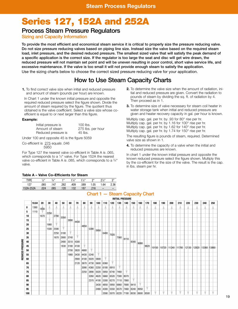
How to Use Steam Capacity Charts
To provide the most efficient and economical steam service it is critical to properly size the pressure reducing valve.Do not size pressure reducing valves based on piping line size. Instead size the valve based on the required steamload, inlet pressure, and the desired reduced pressure. The smallest sized valve that will satisfy the peak demand ofa specific application is the correct size. If the regulator is too large the seat and disc will get wire drawn, thereduced pressure will not maintain set point and will be uneven resulting in poor control, short valve service life, andexcessive maintenance. If the valve is too small it will not provide enough steam to satisfy the application. Use the sizing charts below to choose the correct sized pressure reducing valve for your application.
Series 127, 152A and 252AProcess Steam Pressure RegulatorsSizing and Capacity Information
1. To find correct valve size when initial and reduced pressureand amount of steam (pounds per hour) are known.
In Chart 1 under the known initial pressure and opposite therequired reduced pressure select the figure shown. Divide theamount of steam required by the figure. The quotient thusobtained is the valve coefficient. Select a valve size whose co-efficient is equal to or next larger than this figure.
Example:
Initial pressure is 100 lbs.Amount of steam 275 lbs. per hourReduced pressure is 45 lbs.
Under 100 and opposite 45 is the figure 5059
Co-efficient is 275 equals .0465950
For Type 127 the nearest valve co-efficient in Table A is .065,which corresponds to a 1⁄2" valve. For Type 152A the nearestvalve co-efficient in Table A is .085, which corresponds to a 3⁄4"valve.
2. To determine the valve size when the amount of radiation, ini-tial and reduced pressure are given. Convert the radiation topounds of steam by dividing the sq. ft. of radiation by 4.Then proceed as in 1.
3. To determine size of valve necessary for steam coil heater inwater storage tank when initial and reduced pressure aregiven and heater recovery capacity in gal. per hour is known.
Multiply cap. gal. per hr. by .93 for 80° rise per hr.Multiply cap. gal. per hr. by 1.16 for 100° rise per hr.Multiply cap. gal. per hr. by 1.62 for 140° rise per hr.Multiply cap. gal. per hr. by 1.74 for 150° rise per hr.
The resulting figure is pounds of steam, required. Determinedvalve size as shown in 1.
4. To determine the capacity of a valve when the initial andreduced pressures are known.
In chart 1 under the known initial pressure and opposite theknown reduced pressure select the figure shown. Multiply thisby the co-efficient for the size of the valve. The result is the cap.in lbs. steam per hr.
INITIAL PRESSURE
10.64 20 30 40 50 60 70 80 90 100 110 120 130 140 150 160 170 180 190 200 210 220 230 240 250
0 1360 18305 1110 225010 1670 2790 335015 3890 443020 1980 485025 1500 2590 5390 595030 2250 3180 6480 702035 1670 2900 3740 7560 811040 2480 3510 4300 8540 908045 1830 3180 4100 9620 10150 10720 11240 11780 12130 12820 13360 1386050 2700 3820 4680
55 1980 3430 4430 5240
60 2900 4100 5020 5800
65 2120 3670 4730 5600 6360
70 3090 4360 5350 6180 6910
75 2250 3890 5020 5950 6740 7460
80 3260 4620 5660 6520 7300 8070
85 2370 4100 5300 6270 7110 7860
90 3430 4850 5950 6860 7680 8410
95 2480 4300 5550 6570 7460 8240 8950
100 3590 5070 6220 7180 8030 8800 9500
REDUCED PRESSURE
Table A – Valve Co–Efficients for SteamTYPE 1⁄2" 3⁄4" 1" 11⁄4" 11⁄2" 2" 21⁄2" 3"127 .065 .147 .262 .409 .589 1.05 1.64 2.36
152A-252A .024 .085 .120 .132 .187 .216 – –
Chart 1 — Steam Capacity Chart
Steam Process Regulators
20
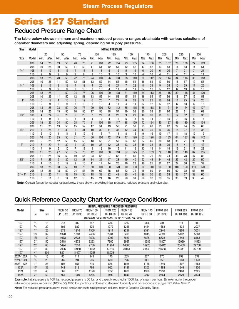
Series 127 StandardReduced Pressure Range Chart
Size Model INITIAL PRESSURE
25 50 75 100 125 150 175 200 225 250Size Model Min. Max. Min. Max. Min. Max. Min. Max. Min. Max. Min. Max. Min. Max. Min. Max. Min. Max. Min. Max.
206 14 25 19 50 20 75 21 100 22 104 23 105 24 106 25 107 26 108 27 109208 10 25 10 50 11 50 11 51 12 51 12 52 13 52 13 53 14 53 14 54
1⁄2" 108 3 17 3 17 4 18 4 18 5 19 5 19 6 20 6 20 7 21 7 21110 2 9 2 9 3 9 3 10 3 10 3 10 4 10 4 11 4 11 4 11206 13 25 20 50 22 75 24 100 26 108 28 110 30 112 32 114 34 116 36 118208 10 25 11 50 12 51 13 52 14 53 15 54 16 55 17 56 18 57 19 58
3⁄4" 108 2 17 3 18 4 19 4 20 6 21 7 22 8 23 9 24 10 25 11 26110 2 9 2 9 3 10 3 10 4 11 4 11 5 12 5 12 6 13 6 13206 13 25 – 50 24 75 26 100 29 108 31 110 34 113 36 115 39 118 41 120208 10 25 11 50 12 51 13 52 14 53 15 54 16 55 17 56 18 57 19 58
1" 108 3 17 4 18 5 19 6 20 7 21 8 22 9 23 10 24 11 25 12 26110 2 9 2 9 3 10 3 10 4 11 4 11 5 12 5 12 6 13 6 13206 13 25 23 50 26 75 29 100 32 112 35 115 38 118 41 121 44 124 47 127208 14 25 15 50 16 55 17 56 18 57 19 58 20 59 21 60 22 61 23 62
11⁄4" 108 4 24 5 25 6 26 7 27 8 28 9 29 10 30 11 31 12 32 13 33110 1 9 2 10 3 11 4 12 4 12 5 13 6 14 7 15 7 15 8 16206 15 25 24 50 28 75 31 100 35 117 38 120 42 124 45 127 49 130 52 134208 11 25 13 50 15 52 17 54 19 56 21 58 23 60 25 62 27 64 29 66
11⁄2" 210 7 25 8 30 9 31 10 32 11 33 12 34 13 35 14 36 15 37 16 38110 3 10 4 11 5 12 6 13 7 14 8 15 9 16 10 17 11 18 12 19206 16 25 25 50 31 75 36 100 42 115 47 120 53 126 58 133 64 137 69 142208 9 25 12 50 15 53 18 56 21 59 24 62 27 65 30 68 33 71 36 74
2" 210 6 29 7 30 9 32 10 33 12 35 13 36 15 38 16 39 18 41 19 42110 4 9 5 10 7 12 8 13 10 15 11 16 13 18 14 19 16 21 17 22206 11 25 27 50 35 75 42 100 50 118 57 125 65 133 72 140 80 148 87 155208 11 25 15 50 19 54 23 58 27 62 31 66 35 70 39 74 43 78 47 82
21⁄2" 210 7 25 9 30 12 33 14 35 17 38 19 40 22 43 24 45 27 48 29 50110 4 10 6 12 9 15 11 17 14 20 16 22 19 25 21 27 24 30 26 32206 18 25 30 50 40 75 50 100 60 120 70 130 80 140 90 150 100 160 110 170208 12 25 18 50 24 56 30 62 36 68 42 74 48 80 54 86 60 92 66 98
3" – 4" 210 8 25 11 32 15 36 18 39 22 43 25 46 29 50 32 53 36 57 39 60110 5 11 8 14 12 18 15 21 16 28 20 31 26 32 29 35 33 39 36 42
Note: Consult factory for special ranges below those shown, providing initial pressure, reduced pressure and valve size.
Quick Reference Capacity Chart for Average ConditionsINITIAL PRESSURE / REDUCED PRESSURE
Model Size FROM 50 FROM 75 FROM 100 FROM 125 FROM 150 FROM 175 FROM 200 FROM 225 FROM 250in mm UP TO 20 UP TO 35 UP TO 50 UP TO 60 UP TO 70 UP TO 80 UP TO 90 UP TO 100 UP TO 125
MAXIMUM CAPACITIES IN LBS. OF STEAM PER HOUR
127 1⁄2 15 218 302 387 474 555 643 731 811 900127 3⁄4 20 492 682 875 1072 1255 1454 1653 1834 2037127 1" 25 878 1216 1560 1911 2237 2591 2946 3268 3631127 11⁄4 32 1370 1898 2436 2984 3493 4045 4599 5102 5668127 11⁄2 40 1973 2733 3508 4297 5030 5825 6623 7348 8163127 2" 50 3518 4872 6253 7660 8967 10385 11807 13099 14553127 21⁄2 65 5494 7610 9766 11964 14006 16220 18442 20459 22730127 3" 80 7906 10950 14054 17216 20154 23440 26538 29441 32709127 4" 100 8301 11497 14756 18076 – – – – –
252A-152A 1⁄2 15 80 111 143 175 205 237 270 299 332252A-152A 3⁄4 20 285 394 506 620 726 841 956 1060 1178252A-152A 1" 25 402 557 715 875 1025 1186 1349 1497 1663
152A 11⁄4 32 442 613 786 962 1127 1305 1484 1646 1830152A 11⁄2 40 665 870 1120 1355 1600 1950 2230 2460 2725152A 2" 50 765 1000 1285 1490 1840 2242 2564 2829 3134
Example; Initial pressure is 100 lbs. reduced pressure is 50 lbs. and capacity required is 1500 lbs. of steam per hour. By referring to the properinitial reduce pressure column (100 to 50) 1560 lbs. per hour is closest to Required Capacity and corresponds to a Type 127 Valve, Size 1".Note: For reduced pressures above those shown for each initial pressure column, refer to Detailed Capacity Table.
The table below shows minimum and maximum reduced pressure ranges obtainable with various selections ofchamber diameters and adjusting spring, depending on supply pressures.
Steam Accessories
21
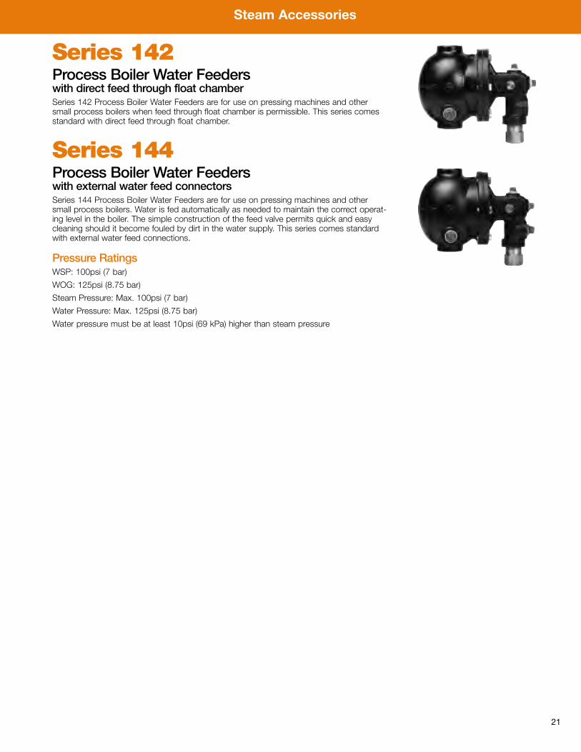
Series 142Process Boiler Water Feederswith direct feed through float chamberSeries 142 Process Boiler Water Feeders are for use on pressing machines and othersmall process boilers when feed through float chamber is permissible. This series comesstandard with direct feed through float chamber.
Series 144Process Boiler Water Feederswith external water feed connectorsSeries 144 Process Boiler Water Feeders are for use on pressing machines and othersmall process boilers. Water is fed automatically as needed to maintain the correct operat-ing level in the boiler. The simple construction of the feed valve permits quick and easycleaning should it become fouled by dirt in the water supply. This series comes standardwith external water feed connections.
Pressure RatingsWSP: 100psi (7 bar)
WOG: 125psi (8.75 bar)
Steam Pressure: Max. 100psi (7 bar)
Water Pressure: Max. 125psi (8.75 bar)
Water pressure must be at least 10psi (69 kPa) higher than steam pressure

PG-Steam 1028 © 2011 Watts
USA: No. Andover, MA • Tel: (978) 688-1811 • Fax: (978) 794-1848 • www.watts.comCanada: Burlington, ON • Tel: (905) 332-4090 • Fax: (905) 332-7068 • www.wattscanada.ca
A Watts Water Technologies Company