steady deflagration structure in two-phase granular
TRANSCRIPT

Steady Deflagration Structure in Two-Phase Granular Propellants
Joseph M. Powers 1 ,
Mark E. Miller2, D. Scott Stewart3, and Herman Krier4
presented at
12th ICDERS, Ann Arbor, Michigan
July 23-28, 1989
1 Assistant Professor, Department of Aerospace and Mechanical Engineering, University of Notre Dame, Notre Dame, Indiana
2 Member of Technical Staff, The Aerospace Corporation, Los Angeles, California
3 Associate Professor, Department of Theoretical and Applied Mechanics, University of illinois at Urbana-Champaign, Urbana, illinois
4 Professor, Department of Mechanical and Industrial Engineering, University of Illinois at Urbana-Champaign, Urbana, Illinois
This work was performed with the support of the U.S. ONR, Contract N00014-86-K-0434; Dr. Richard S. Miller, Program Manager
•
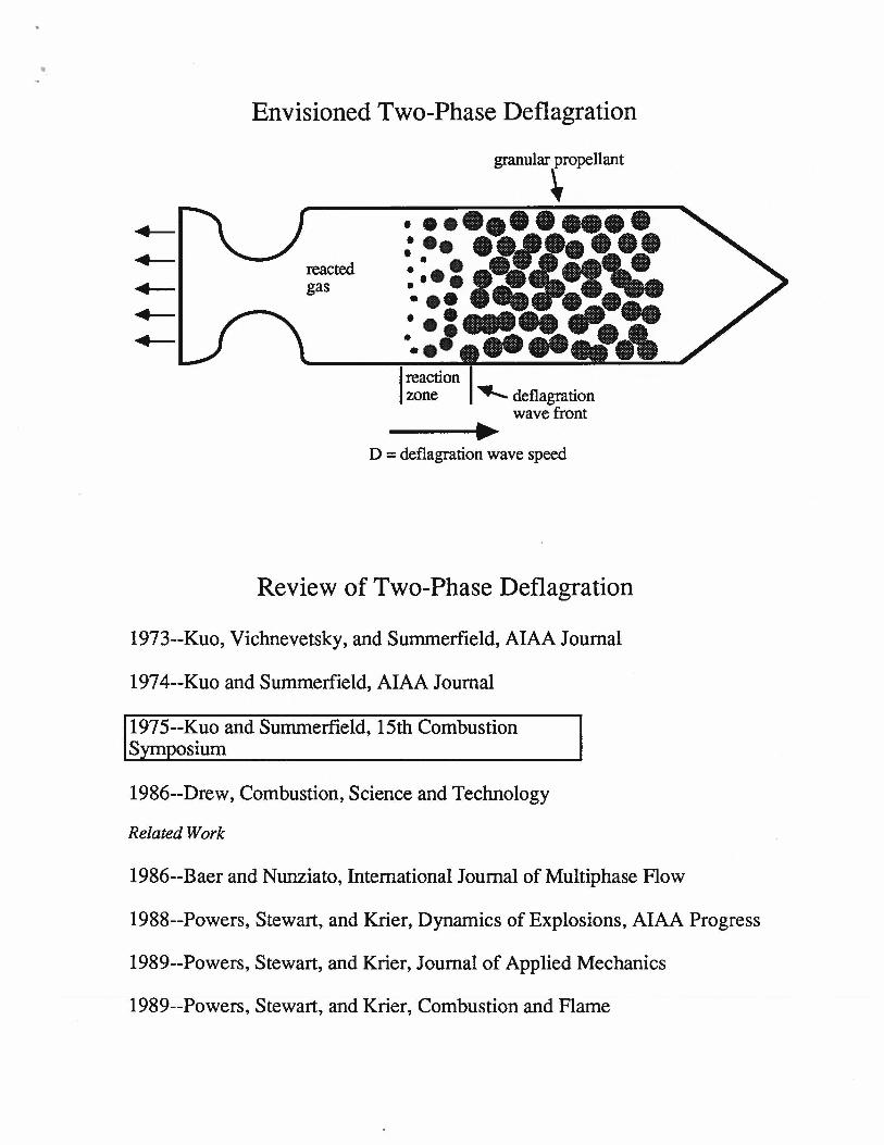
Envisioned Two-Phase Deflagration
reacted gas
granular propellant
• ........... ~:::,~I/~~ ... ~"'· ... :.:i':\~--·A ---------
1 reaction I zone ~ deflagration
wave front
D = deflagration wave speed
Review of Two-Phase Deflagration
1973--Kuo, Vichnevetsky, and Summerfield, AIAA Journal
1974--Kuo and Summerfield, AIAA Journal
1975--Kuo and Summerfield, 15th Combustion S_ym_Q_osium
1986--Drew, Combustion, Science and Technology
Related Work
1986--Baer and Nunziato, International Journal of Multiphase Flow
1988--Powers, Stewart, and Krier, Dynamics of Explosions, AIAA Progress
1989--Powers, Stewart, and Krier, Journal of Applied Mechanics
1989--Powers, Stewart, and Krier, Combustion and Flame
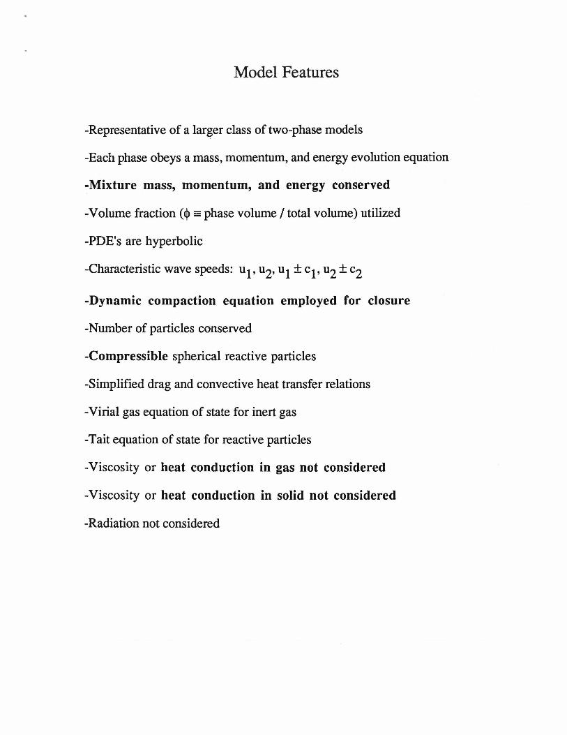
Model Features
-Representative of a larger class of two-phase models
-Each phase obeys a mass, momentum, and energy evolution equation
-Mixture mass, momentum, and energy conserved
-Volume fraction ( <j> = phase volume I total volume) utilized
-PDE's are hyperbolic
-Characteristic wave speeds: u1, u2, u1 + c1, u2 + c2
-Dynamic compaction equation employed for closure
-Number of particles conserved
-Compressible spherical reactive particles
-Simplified drag and convective heat transfer relations
-Virial gas equation of state for inert gas
-Tait equation of state for reactive particles
-Viscosity or heat conduction in gas not considered
-Viscosity or heat conduction in solid not considered
-Radiation not considered

Two-Phase Model Equations
-ordinary differential equations in steady wave frame
-~ = distance in steady wave frame ~ = ~ -Dt
-D = steady wave speed
-with additional algebraic equations, the model can be represented by four differential equations in four unknowns
particle mass
de2 dv2 <1>1 [T -T J p v -+P - = -h- 2 1, 2 2 dl; 2 dl; r 1/3
particle energy
dynamic pore collapse

Conservation Relations
-obtained by integrating conservative differential equations
-initial conditions specify integration constants
1) Mixture mass, momentum, and energy:
p1<j>1v 1[ e1+v~/2+P /P1] + p2q,2vJ e2+v}2+P /P2] = -Pa1::{ ea+D2/2+P /Pal
mixture energy
- "a" denotes apparent or bulk initial property
Pa = P10<l>10 + P20<l>20'
pa = P10<l>10 + P20<l>20·
2) Particle number equation:
apparent initial density
apparent initial pressure
apparent initial energy

Gas and Particle State Equations 1) Gas:
p = p RT ( 1 + bp ) 1 1 1 1 '
gas thermal
el = cvlTl" gas caloric
2) Particle:
particle thermal
particle caloric
Saturation condition:
cj> + cj> = 1. I 2

Initial Conditions
-Eight independent initial conditions specified for original eight differential equations
-Temperature and density for each phase
-Velocity for each phase
-Initial particle radius
-Initial volume fraction
-Specified so that initial state is an equilibrium state
-Remaining initial conditions fixed by state equations and saturation
condition:

Dimensional Input Parameters
a [m/ (s Pa)] 2.90 x 10⁻⁹
Pio [kg /m3] 1.00 x 100
m 1.00 x 100
~ [kg I (s m2)] 1.00 x 10⁴
P20 [kg/m3] 1.90 x 10³
h [JI (s K m8f3)] 1.00 x 10⁷
Cvl [JI (kg K)] 2.40 x 10³
Cv2 [JI (kg K)] 1.50 x 10³ R [JI (kg K)] 8.50 x 10²
O' [(m I s)2] 7.20 x 10⁶
q [JI kg] 5.84 x 10⁶
To [m] 1.00 x 10⁻⁴
b [m3 I kg] 1.10 x lQ-3
Y2 5.00 x 10°
µc [kg I (ms)] 1.25 x 10²
To [K] 3.00 x 10²
Tig [K] 3.00 x 10²+

Two-Phase Deflagration End States
-arbitrarily assume complete reaction
-mixture equations define two-phase Rayleigh line and Hugoniot equations
Rayleigh line
Hugoniot
-In general, two physical deflagration solutions for a given wave speed D
1) Low pressure, supersonic, strong solution 2) High pressure, weak, subsonic solution
-Maximum deflagration wave speed at CJ condition, sonic solution
1WO-PHASE HUGONIOT ~
/WEAK SOLUTION (SUBSONIC)
CJ SOLUTION_.. (SONIC)
STRONG SOLUTION #"' (SUPERSONIC)
J' RAYLEIGH LINE D=DcJDEF
1/pl
RAYLEIGH LINE D<DcJDEF
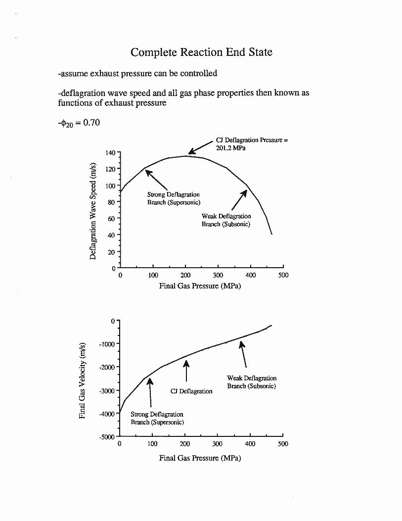
Complete Reaction End State
-assume exhaust pressure can be controlled
-deflagration wave speed and all gas phase properties then known as functions of exhaust pressure
-<l>io = 0. 70
140
-~ 120 ..._.,
13 100 8.
Cl)
~ 80
60 c:: 0 ·a ~ 40 ro
i;::: 20 Cl.)
Cl
0 0
0
- -1000 ~ ..._., 0 -2000 ...... 8 -> Vl -3000 ro 0 ca .s -4000 ~
-5000 0
/ CJ Deflagration Pressure = k:' 201.2 MPa
Strong Deflagration Branch (Supersonic)
100 200
Weak Deflagration Branch (Subsonic)
300 400
Final Gas Pressure (MPa)
Weak Deflagration
CJ Deflagration Branch (Subsonic)
Strong Deflagration Branch (Supersonic)
100 200 300 400
Final Gas Pressure (MPa)
500
500

CJ Deflagration State
-CJ state can be determined numerically
-Simple analytic expression in two limits
1) ideal gas b = 0 2) PJ(Pa ea)~ 0
2 e T - a
CJ= -, 'Y1 ("(1 + 1) cvl
2 e = e
CJ - 'Y 1("(1 + 1) a'
(
2 ('Y1 - 1) e )
r + 1 a 1

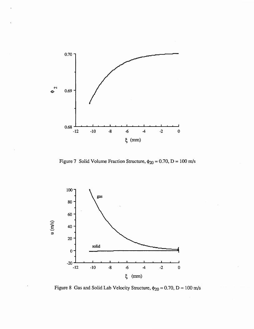
Two-Phase Deflagration Structure
-Ordinary differential equations integrated for D = 100 m/s
-Arbitrarily assumed that no shocks exist in structure or no sonic points
-With this assumption the end state is weak subsonic end state
-exhaust pressure ,.., 400 MPa
-Extreme deflagration exhaust conditions because some parameters arbitrarily chosen so that a numerically resolved structure could be presented
-No two-phase steady detlagration structure going to complete reaction was found
0.70
N -e- 0.69
0.68 ____ ...__..__,___...__._.,__..__.... ___ -A.-________ ...._.
-12 -10 -8 -6 -2 0
~ (mm)
Figure 7 Solid Volume Fraction Structure, <1>20 = 0.70, D = 100 m/s
100
80
60 -(ll a 40 ........, ::s
20
0
-20 -12 -10 -8 -6 4 -2 0
~ (mm)
Figure 8 Gas and Solid Lab Velocity Structure, <1>20 = 0.70, D = 100 m/s

103 solid
102
'2 Q.. 101 ::E '-" Q..
100
gas
10-l -12 -10 -8 -6 -4 -2 0
; (mm)
Figure 9 Gas and Solid Pressure Structure, 4>20 = 0.70, D = 100 m/s
103
-~ '-"
E-< solid
102
101 -12 -10 -8 -6 -4 -2 0
; (mm)
Figure 10 Gas and Solid Temperature Structure, 4>20 = 0.70, D = 100 m/s

10-l
10-2 gas
10-3 solid
10-4
<'I 10-5 :;E
10-6
10-7
10-8
10-9 -12 -10 -8 -6 -4 -2 0
~ (mm)
Figure 11 Gas and Solid Mach Number Squared, <1>20 = 0.70, D = 100 m/s

,
Conclusions
-Possible to predict gas phase deflagration end state and wave speed as function of exhaust pressure and initial conditions
-For the region of parameter space studied, no steady two-phase deflagration structure exists
-Processes that support detonation are not sufficient to support a two-phase deflagration
-It may be necessary to include heat conduction and radiation to model twophase deflagrations
-Combustion of granulated propellants could possible accelerate into steady, self-propagating two-phase detonation