stawell aerodrome master plan
TRANSCRIPT
NORTHERN GRAMPIANS SHIRE COUNCIL
D R A F T
STAWELL AERODROME MASTER PLAN REVIEW
November 2014
prepared by
AIRPORTS PLUS PTY LTD ACN 090 604 425
Tel: 0413 868 013 / 03 5426 2544
Stawell Aerodrome
Airports Plus Pty Ltd Master Plan Review November 2014 Page 2
CONTENTS 1 INTRODUCTION ........................................................................................ 3
1.1 Aviation terminology used in this Master Plan Review .................. 3
2 AIRCRAFT PLANNING CRITERIA ............................................................ 3 2.1 Aerodrome Reference Code .......................................................... 3 2.2 Determining runway length, width and strength ............................. 4 2.3 Selected design aircraft ................................................................. 5
3 AIRCRAFT ACTIVITY FORECAST ........................................................... 6
4 EXISTING FACILITIES .............................................................................. 6 4.1 Runways ........................................................................................ 6 4.2 Taxiways and apron ....................................................................... 7 4.3 Terminal ......................................................................................... 8 4.4 Hangars .......................................................................................... 8 4.5 Other facilities ................................................................................ 8
5 ASSESSMENT OF FACILITIES ................................................................ 9 5.1 Background .................................................................................... 9 5.2 Aircraft pavements ....................................................................... 10 5.3 Physical characteristics ................................................................ 10 5.4 Current deficiencies ..................................................................... 10 5.4.1 Land ownership ............................................................................ 10 5.4.2 Runways and taxiways ................................................................ 10 5.4.3 General aviation (GA) areas ........................................................ 11
6 FUTURE AERODROME FACILITY REQUIREMENTS ........................... 11 6.1 Growth factors .............................................................................. 11 6.2 Land ownership ............................................................................ 11 6.3 Runways ...................................................................................... 12 6.4 Taxiways ...................................................................................... 13 6.5 Aircraft parking areas ................................................................... 13 6.6 Future hangar development ......................................................... 14 6.7 Aviation fuel .................................................................................. 14 6.8 Vehicle access to the aerodrome ................................................. 15
7 FUTURE AERODROME UTILITY REQUIREMENTS .............................. 15 7.1 Electricity ...................................................................................... 15 7.2 Water ............................................................................................ 15 7.3 Sewerage ..................................................................................... 15 7.4 Telephone .................................................................................... 16
8 PLANNING CONTROLS .......................................................................... 16 8.1 Planning update ........................................................................... 16
9 SUMMARY OF THE MASTER PLAN REVIEW ....................................... 16 9.1 Trigger points ............................................................................... 17
PLAN 1 – Current Aerodrome Layout .............................................. 19
PLAN 2 – Crown Land v Council Land ............................................ 20
PLAN 3 – Stages 1, 2 and 3 Hangar Development .......................... 21
PLAN 4 – Runway 11/29 possible extensions ................................. 22
Stawell Aerodrome
Airports Plus Pty Ltd Master Plan Review November 2014 Page 3
1 INTRODUCTION Airports Plus Pty Ltd was commissioned by the Northern Grampians Shire Council (NGSC) in 2008 to undertake a Master Plan for the future development of facilities and infrastructure at Stawell Aerodrome. The NGSC adopted this Master Plan on 29 January 2009. Considerable development has occurred at Stawell Aerodrome since the adoption of the Master Plan. As a result this review was commissioned to bring the Master Plan document up to date and to accommodate any future development. This review is based on discussions with Mr Allan Ralph, Contract Engineer, NGSC, and the provision of an amended Master Plan Review document. The review also involved an inspection of the aerodrome. Up to date feature survey plans provided by NGSC have been used as the basis for plans contained in this review as well as proposed development plans for specific facilities on the aerodrome.
1.1 Aviation terminology used in this Master Plan Review General Aviation (GA) is defined as all aviation activity at civil airports, other than Regular Public Transport (RPT), by international and domestic airlines. GA is divided into a number of sectors that includes air charter, private and corporate flying, local flying, pilot training and aerial work. Pilot training and aerial work dominate total GA hours flown in Australia. Helicopter operations are also normally classified as GA. Regular Public Transport (RPT) is a term used to define a scheduled airline service.
2 AIRCRAFT PLANNING CRITERIA
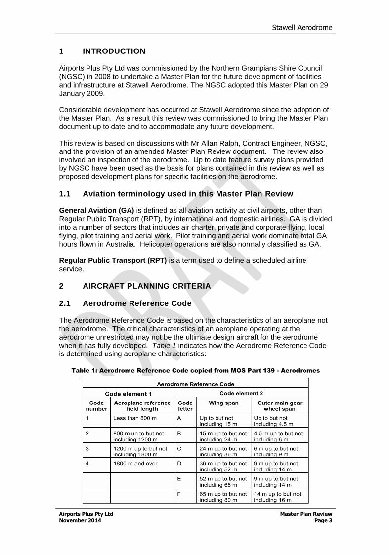
2.1 Aerodrome Reference Code The Aerodrome Reference Code is based on the characteristics of an aeroplane not the aerodrome. The critical characteristics of an aeroplane operating at the aerodrome unrestricted may not be the ultimate design aircraft for the aerodrome when it has fully developed. Table 1 indicates how the Aerodrome Reference Code is determined using aeroplane characteristics:
Table 1: Aerodrome Reference Code copied from MOS Part 139 - Aerodromes
Stawell Aerodrome
Airports Plus Pty Ltd Master Plan Review November 2014 Page 4
Code elements 1 and 2 in the table above account for the aircraft take-off performance and the physical dimensions of the aircraft. Each aircraft can then be categorised for the purposes of planning the facilities, required by that particular aircraft, to operate using those facilities. Facilities that are not fully compliant with the standards found in MOS Part 139 - Aerodromes can still be used by aircraft with higher code numbers at the pilot’s discretion. An example is a Code 3C aircraft operating on a Code 2B runway where the pilot predetermines that there are suitable safety margins in place for that aircraft to operate. The Aerodrome Reference Code does not take into account the Maximum Take-off Weight (MTOW) of the aircraft. The construction of pavements to handle aircraft operating at the aerodrome is an engineering and economic decision based on many factors. Currently there are no standards applied by the Civil Aviation Safety Authority (CASA) regarding minimum pavement strengths. For a pavement to be determined suitable for an aircraft operation the designated Pavement Classification Number (PCN) should match the Aircraft Classification Number (ACN) determined by the aircraft manufacturer. It is common practice in Australia for airport operators to issue Pavement Concessions to allow aircraft with higher ACN numbers to operate on pavements that have lower PCNs.
2.2 Determining runway length, width and strength The first step, when making a decision on what physical standards should be applied to an aerodrome through its development life, is to determine the most likely aircraft types that will operate. The aircraft that best represents the range of aircraft that could operate is then selected. The design aircraft will dictate the runway length, the width of the runway and taxiways, and the strength of all aircraft pavements. It is not expected that Stawell Aerodrome will attract scheduled airline services (RPT) in the next ten years. It is possible that charter passenger services could occasionally operate for specific events. It is also possible that larger aircraft types will be used for fire suppression activities in the next five - ten years. There are a number of aircraft commonly used in the Australian aviation industry for small passenger operations and for corporate charter. The majority of passenger operations into regional centres on the eastern seaboard are serviced by turbo prop aircraft with a seating capacity up to 70 passengers. The two most common aircraft types are Dash 8 and SAAB 340. The majority of Dash 8 aircraft are operated by Qantaslink who are currently upgrading their fleet from Dash 8-200 and Dash 8-300 to Dash 8-400 aircraft. There are also aircraft operators in Australia with Dash 8-200 aircraft in their fleet available for charter. The majority of SAAB 340 aircraft are operated by Regional Express. These aircraft are often chartered for the transport of passengers to a specific location. The most common types of corporate aircraft used in Australia are the Canadair Challenger 604, which are generally used by the RAAF to transport VIPs, and the Cessna Citation/Learjet or similar which are used by many businesses as charter aircraft. Beechcraft King Air 200 aircraft are used by Pel Air Aviation Pty Ltd (Pel-Air), the current contractor for Ambulance Victoria, and are also often used as a charter aircraft. The Aeroplane Reference Field Length (ARFL), published by aircraft manufacturers for each aircraft type is part of the certification process and is only a guide when determining suitable runway length. There are many other factors that can influence
Stawell Aerodrome
Airports Plus Pty Ltd Master Plan Review November 2014 Page 5
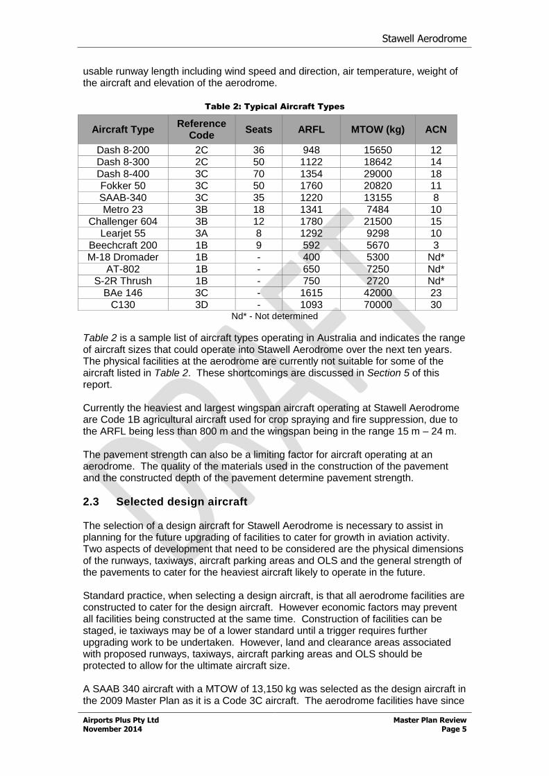
usable runway length including wind speed and direction, air temperature, weight of the aircraft and elevation of the aerodrome.
Table 2: Typical Aircraft Types
Aircraft Type Reference
Code Seats ARFL MTOW (kg) ACN
Dash 8-200 2C 36 948 15650 12 Dash 8-300 2C 50 1122 18642 14
Dash 8-400 3C 70 1354 29000 18 Fokker 50 3C 50 1760 20820 11
SAAB-340 3C 35 1220 13155 8 Metro 23 3B 18 1341 7484 10
Challenger 604 3B 12 1780 21500 15 Learjet 55 3A 8 1292 9298 10
Beechcraft 200 1B 9 592 5670 3 M-18 Dromader 1B - 400 5300 Nd*
AT-802 1B - 650 7250 Nd* S-2R Thrush 1B - 750 2720 Nd*
BAe 146 3C - 1615 42000 23 C130 3D - 1093 70000 30
Nd* - Not determined
Table 2 is a sample list of aircraft types operating in Australia and indicates the range of aircraft sizes that could operate into Stawell Aerodrome over the next ten years. The physical facilities at the aerodrome are currently not suitable for some of the aircraft listed in Table 2. These shortcomings are discussed in Section 5 of this report. Currently the heaviest and largest wingspan aircraft operating at Stawell Aerodrome are Code 1B agricultural aircraft used for crop spraying and fire suppression, due to the ARFL being less than 800 m and the wingspan being in the range 15 m – 24 m. The pavement strength can also be a limiting factor for aircraft operating at an aerodrome. The quality of the materials used in the construction of the pavement and the constructed depth of the pavement determine pavement strength.
2.3 Selected design aircraft The selection of a design aircraft for Stawell Aerodrome is necessary to assist in planning for the future upgrading of facilities to cater for growth in aviation activity. Two aspects of development that need to be considered are the physical dimensions of the runways, taxiways, aircraft parking areas and OLS and the general strength of the pavements to cater for the heaviest aircraft likely to operate in the future. Standard practice, when selecting a design aircraft, is that all aerodrome facilities are constructed to cater for the design aircraft. However economic factors may prevent all facilities being constructed at the same time. Construction of facilities can be staged, ie taxiways may be of a lower standard until a trigger requires further upgrading work to be undertaken. However, land and clearance areas associated with proposed runways, taxiways, aircraft parking areas and OLS should be protected to allow for the ultimate aircraft size. A SAAB 340 aircraft with a MTOW of 13,150 kg was selected as the design aircraft in the 2009 Master Plan as it is a Code 3C aircraft. The aerodrome facilities have since
Stawell Aerodrome
Airports Plus Pty Ltd Master Plan Review November 2014 Page 6
been upgraded to cater for the design aircraft. This review continues to support the design aircraft being a SAAB 340.
3 AIRCRAFT ACTIVITY FORECAST Aircraft activity forecasts are usually included in Master Plans but there are no historical statistics of annual aircraft activity available for Stawell Aerodrome. It was determined that preparation of an aircraft activity forecast was not required due to the nature of GA aircraft operations at Stawell Aerodrome. The largest single flying activity is conducted during the summer fire season when the aerodrome is used as a base for fire suppression aircraft. Some light aircraft flying training is also undertaken on a regular basis and the aerodrome is used as a base for contractors using agricultural aircraft for crop spraying activities. The aircraft movement capacity of the current runway configuration is much greater than the actual number of aircraft movements and therefore there is no need to calculate the busiest peak hour or forecast the busiest peak hour for the next 10 years. The current physical runway configuration has the capacity for handling over 60,000 movements per annum. The number of aircraft movements has not changed since the 2009 Master Plan and are in the range of 10,000 – 12,000 movements per annum.
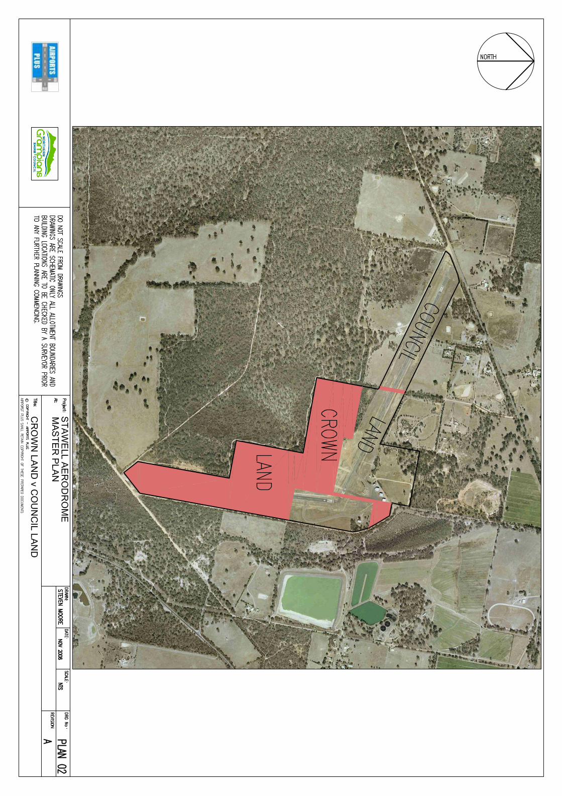
4 EXISTING FACILITIES Stawell Aerodrome is situated 4 km southwest of the city of Stawell. The aerodrome elevation is 807 feet (246m AHD). The aerodrome is situated on 90 ha of land; 43.4 ha are owned by the NGSC and the remaining 46.6 ha is Crown Land. The Council is appointed as the Committee of Management. Runway 11/29, the two primary taxiways, a secondary taxiway and half the aircraft parking areas are situated on land owned by the NGSC. A small portion of Runway 18/36 is situated on NGSC land. The remainder of Runway 18/36 and half the aircraft parking area, which contains the aircraft refuelling facility, are situated on Crown Land.
4.1 Runways Runway 11/29 is 1403 m long and 30 m wide and is contained in a runway strip 1523 m long and 90 m wide and has been fully reconstructed since the 2009 Master Plan. The runway now includes turning nodes at each end of the runway. The central 23 m of runway surface consists of a double bituminous sprayed seal with a 10 mm/7 mm aggregate wearing course. The runway surface was provided with a Surface Enrichment Spray Treatment (SEST) in April 2014 to prolong the life of the wearing course. The runway is currently published in ERSA RDS as a Code 3 runway. The current pavement rating, published in ERSA, shows the runway has a PCN of 9 on a sub-grade classified as D with a tyre pressure rating of 450 kPa (65 psi) which allows aircraft with an ACN up to 9 to operate without restriction. The runway is equipped with a single stage low intensity runway edge lighting system. The runway lights can be activated by pilots on a dedicated radio frequency 119.2 MHz.
Stawell Aerodrome
Airports Plus Pty Ltd Master Plan Review November 2014 Page 7
Runway 11/29 is the primary runway due to the prevailing wind and night lighting. Aircraft operating on Runway 11 operate normal left hand circuits but are required to operate right hand circuits when using Runway 29 at night due to high terrain. An RNAV (GNSS) approach procedure has been provided under contract from Airservices Australia (AA) for both Runway 11 and Runway 29. This procedure allows pilots to fly down to a minima on Runway 29 of 703 ft above the ground and 4 nautical miles from the threshold and on Runway 11 down to a minima of 528 ft and three nautical miles from the threshold. These procedures now enable aircraft to operate into Stawell Aerodrome in inclement weather as long as when the minima is reached the runway is visible. Runway 18/36 is 854 m long and 18 m wide and is contained in a runway strip 974 m long and 90 m wide. The runway has a bituminous sprayed seal with a 10 mm/7 mm aggregate wearing course. The surface was provided with a SEST in April 2014. The runway is currently deemed to be a Code 1A runway. The pavement is rated for aircraft up to a MTOW 5,700 kg with a tyre pressure of 450 kPa (65 psi). Aircraft operate normal left hand circuits when operating on Runway 36 but right hand circuits when operating on Runway 18 due to high terrain. No lighting is available on this runway for night operations.
4.2 Taxiways and apron Taxiway A. The old Taxiway A has been closed to aircraft traffic and a new Code C Taxiway A has been constructed west of the old Taxiway A and provides access to a newly constructed apron from Runway 11/29. This 15 m wide taxiway has a bituminous sprayed seal surface with a 10 mm/7 mm aggregate wearing course. The surface of the taxiway was provided with a SEST in April 2014. The taxiway has night lighting consisting of blue taxiway edge lighting. Taxiway B links Runway 11/29 with the aircraft parking area and the hangars and enters the runway approximately 40 m from the threshold of Runway 29. The taxiway has a bituminous sprayed seal surface with a 10 mm aggregate wearing course. The taxiway has an average width of 9 m, making it suitable for unrestricted use by Code A aircraft and restricted use by Code B aircraft. The taxiway has a longitudinal slope marginally in excess of the standard applicable for a Code A taxiway. The taxiway has night lighting consisting of blue taxiway edge lighting, installed during the recent runway upgrade works. Taxiway C links the aircraft parking area with Runway 18/36 and enters the runway approximately 150 m from the threshold of Runway 18. The taxiway has a bituminous sprayed seal surface with a 10 mm aggregate wearing course and has an average width of 8 m making it suitable for Code A aircraft. The longitudinal slope of this taxiway is applicable for a Code A taxiway. The taxiway strip associated with this taxiway is not compliant with the MOS Part 139 – Aerodromes standards and is subject to a CASA non-compliance notice. The Terminal Apron was constructed as part of the aerodrome upgrade works and is 1925 m2. It has a bituminous sprayed seal surface with a 10 mm/7 mm aggregate wearing course and was also provided with a SEST in April 2014. There is one parking position provided on the apron for aircraft up to SAAB 340. The Main Apron is approximately 7,500 m2 and provides aircraft parking areas. The apron has a bituminous sprayed seal surface with a 10 mmm aggregate wearing course. Approximately 1,000 m2 of this area has been constructed in the last two
Stawell Aerodrome
Airports Plus Pty Ltd Master Plan Review November 2014 Page 8
years and has a bituminous sprayed seal surface with a 7 mm aggregate wearing course. Some areas on the apron are provided with aircraft tie-down points.
4.3 Terminal A Terminal has been established adjacent to the Terminal Apron which contains toilets, a kitchen area, tables and chairs and a storeroom for the storage of aerodrome equipment. Adjacent to the Terminal is a gate which allows ambulance vehicles undertaking patient transfers direct access to aircraft on the parking position.
4.4 Hangars Four hangars are located on the west side of the main apron. The most southerly hangar, operated by AGA Services, has been enlarged by an additional 600 m2 for the maintenance and storage of aircraft. The western portion of this hangar has been redeveloped and now contains offices, pilot training facilities and amenities. Two smaller GA hangars are located east of Taxiway C. A short private taxiway provides access to the hangars. This taxiway is not compliant with MOS Part 139 – Aerodromes for a Code A taxiway. An office and pilot training room are located in a building on the west side of the AGA Services’ hangar. There is another small building, which is used for storage and as an office/pilot rest area (old Department of Transport building), located east of Taxiway A. The Department of Environment and Primary Industries (DEPI) has established a major fire suppression base at Stawell Aerodrome for the Grampians Region. The DEPI has installed water tanks and erected a building that contains fire suppression mixing equipment which is then piped underground to a concrete filling pad for quick filling of aircraft during fire suppression activities. A mobile caravan has been permanently located at the aerodrome as a fire control room and is located adjacent to the equipment building. A gravel taxiway provides access to the concrete filling pad from Runway 18/36. DEPI has completed a master planning process which indicates that the site will have further buildings established which will include accommodation and amenities for up to 100 fire fighters. This work is not expected to commence until mid – late 2015 but may commence earlier.
4.5 Other facilities The refuelling facility has been upgraded as there was insufficient storage capacity on site and the facility could not be accessed 24 hours/day as there was no floodlighting available so that aircraft could safely refuel. The NGSC provided upgraded electrical power and lighting for the site and AGA Services who operate the site under a long term lease provided the new fuel facility including credit card readers. The upgraded facility has increased the storage capacity of Jet A1 to 58,000 litres and AVGAS to 20,000 litres. A fuel truck operated by AGA Services is used to dispense Jet A-1 fuel to aircraft as required. An Automatic Weather Station (AWS) which is owned and operated by the Bureau of Meteorology (BoM) is located southwest of the intersection of both runways. The NGSC installed an Automatic Weather Information Service (AWIS) facility in 2013. The AWIS can be accessed by pilots on frequency 122.575 MHz or by telephone on 03 5358 1311.
Stawell Aerodrome
Airports Plus Pty Ltd Master Plan Review November 2014 Page 9
Electricity is supplied to the aerodrome site via overhead power lines that enter the northern boundary of the aerodrome. These lines have been extended and placed underground to the rear of the building line adjacent to the aircraft parking apron. A new main distribution cabinet has been installed and the power supply has been upgraded to 3-phase. Any future electrical power supply to hangars will need to be placed underground so that there is no interference with aircraft operations when the new taxiways are constructed. A standby emergency power generator has been installed that can provide emergency power for essential facilities including runway, taxiway and apron floodlighting during a primary power outage. The water supply for the aerodrome site is located on the north-eastern boundary immediately adjacent to the two small hangars adjacent to Taxiway C. It is planned to upgrade the water supply so that there is more volume available for fire suppression activities; this upgrade is identified in the DEPI Draft Master Plan for their facilities. A need to increase the water storage capacity has also been identified in the DEPI Draft Master Plan. Water storage tanks were installed as part of the fire protection requirements for the AGA Services hangar when it was enlarged. These tanks are located adjacent to the Terminal. Sewerage is not connected to Stawell Aerodrome. The Terminal and hangar toilets have been connected to a new septic collection system that was installed as part of the airport development works. This system has provision and capacity for future connection to hangars and other buildings. The system has been installed to the north of the existing hangar area as discussed in the previous Master Plan. Telephone is connected to the aerodrome via a pillar located on the corner of the fence adjacent to the old road entry point which leads onto the aircraft parking apron.
5 ASSESSMENT OF FACILITIES
5.1 Background After the adoption of the 2009 Master Plan, NGSC sought funding to assist in implementing the major outcomes of the Master Plan. As a result of the granting of funds from the Victorian State Government the facilities on the aerodrome have been significantly upgraded to cater for larger aircraft and increased aircraft movements including:
the reconstruction of Runway 11/29
the construction of a new Code C taxiway and apron
the construction of a Terminal
the construction of additional apron areas for GA aircraft
the upgrade of the electricity supply
the relocation of the runway lighting to meet current CASA standards
the upgrade of the aircraft refuelling facilities
the provision of RNAV GNSS approach procedures for RWY 11/29
the provision of an AWIS
Stage 1 - implementation of the roadway system for accessing existing and future hangars
Stawell Aerodrome
Airports Plus Pty Ltd Master Plan Review November 2014 Page 10
the installation of a new septic tank system
the installation of upgraded road and hangar drainage
5.2 Aircraft pavements Runway 11/29 now has a published PCN 9 and a tyre pressure rating of 450 kPa (65 psi) which is suitable for all of the aircraft currently operating at the aerodrome and for the design aircraft. A number of larger aircraft could also use the aerodrome if they were operating with a reduced MTOW. The provision of the Code C taxiway and apron has greatly enhanced the flexibility of the aerodrome to handle larger aircraft.
5.3 Physical characteristics The adoption of a Code 3C aircraft as the design aircraft for applying physical standards has ensured that the upgraded facilities already in place have greatly enhanced the future potential use of the aerodrome.
5.4 Current deficiencies 5.4.1 Land ownership Since the adoption of the previous Master Plan no negotiations have commenced regarding the transfer or land swap of the sections of Crown Land managed by NGSC to Council ownership. This means that a portion of Runway 18/36 and an area of aircraft parking apron from the fuel facility to the northeast boundary fence and the entire forest area to the west of Runway 18/36 is Crown Land is only managed by NGSC for aerodrome use (refer Plan 2). An example of the consequences of the NGSC not owning the Crown Land is illustrated by the two road reserves that separate the NGSC titles. One road reserve dissects Runway 11/29 and the other is the extension of Aerodrome Road through the aircraft parking area and down the centreline of Runway 18/36. Consolidation of the Council titles including the road reserves which separate the titles would ensure some certainty for future development options over the next 10 – 40 years. 5.4.2 Runways and taxiways Runway 18/36 is suitable for current light aircraft operations when cross winds reduce the useability of Runway 11/29. Terrain to the south effectively inhibits any upgrade of the runway, particularly any increase in the length of the runway. The taxiway linking Runway 11/29 with the GA parking apron does not meet Code B width and longitudinal slope requirements. The runway strip for Runway 11/29 has been fully graded to a width of 90 m and meets the minimum standards but a fly-over area of an additional 30 m either side of the graded portion is infringed by trees on the northern side of the runway. These trees are not on aerodrome property and negotiations will need to be undertaken at some time in the future to reduce their height so that the total runway strip of 150 m can be established as required by MOS Part 139 – Aerodromes, Table 6.2-6.
Stawell Aerodrome
Airports Plus Pty Ltd Master Plan Review November 2014 Page 11
5.4.3 General aviation (GA) areas The GA areas at Stawell Aerodrome are substantial and currently meet the demands for aircraft parking. However, two infill areas either side of Taxiway B should be constructed and sealed to assist aircraft movements and provide additional aircraft parking areas. There is adequate land available for the future development of hangars and associated taxiways and aprons.
6 FUTURE AERODROME FACILITY REQUIREMENTS
6.1 Growth factors The growth factors that have influenced Stawell Aerodrome’s development in the last five years are still relevant and will continue to influence future development. The use of the aerodrome as a major fire suppression base for the DEPI has seen an increase in the number of aircraft based at the aerodrome. This has led to the major aviation tenant expanding their facilities to cater for this growth and to also consolidate their business interests at the aerodrome. DEPI is in the process of expanding their facilities to cater for a larger number of fire crew and support staff to be based at the aerodrome during fire events across Western Victoria. The upgrade of the runway and the addition of a Code C taxiway and apron will allow larger aircraft to operate from the aerodrome, particularly fire suppression aircraft. The State Government has leased a C130 and a BAe146 for the 2014/2015 fire season as a trial to assess the effectiveness of these aircraft. If the trial proves satisfactory then C130 aircraft could operate from Stawell Aerodrome in the future. There has been some fly-in/fly-out (FIFO) activity in the last two years due to there being a number of mining personnel who reside in Stawell. This activity is influenced by world markets and the production rates of mines that may require an increase in personnel from time to time. The presence of a Terminal and 24 hour refuelling facilities encourages and supports this type of operation. There have been no new tourism initiatives in Stawell or the Grampians that have led or will lead to an increase in aircraft activity at this time.
6.2 Land ownership As indicated earlier the resolution of the ownership of the entire aerodrome site should be pursued to remove any uncertainty that may restrict future development options for the aerodrome. Alternative plans such as a partial swap of unused sections of Council freehold land with key sections of DEPI crown land may be a more cost effective method of securing the main hangar and airside areas under Council ownership. Long term leases on hangar sites, i.e. 40 years can only be provided if the Council has ownership of these sites. This can be important for securing bank loans and attracting new businesses. Leasing is a preferred option as it provides Council with planning control over the use of hangar sites and the types of businesses that can be undertaken in these hangars. If the sites are sold under a subdivision arrangement then that control diminishes and
Stawell Aerodrome
Airports Plus Pty Ltd Master Plan Review November 2014 Page 12
the sites can be on sold and then inappropriate use can occur, i.e. non-aviation use of the hangar. The consolidation of all land titles relating to the site should be a priority. This would ensure that the entire aerodrome site is contained on one title to assist with protection of the aerodrome under the NGSC planning scheme and ensure that future development planning on the site can occur under NGSC control. .
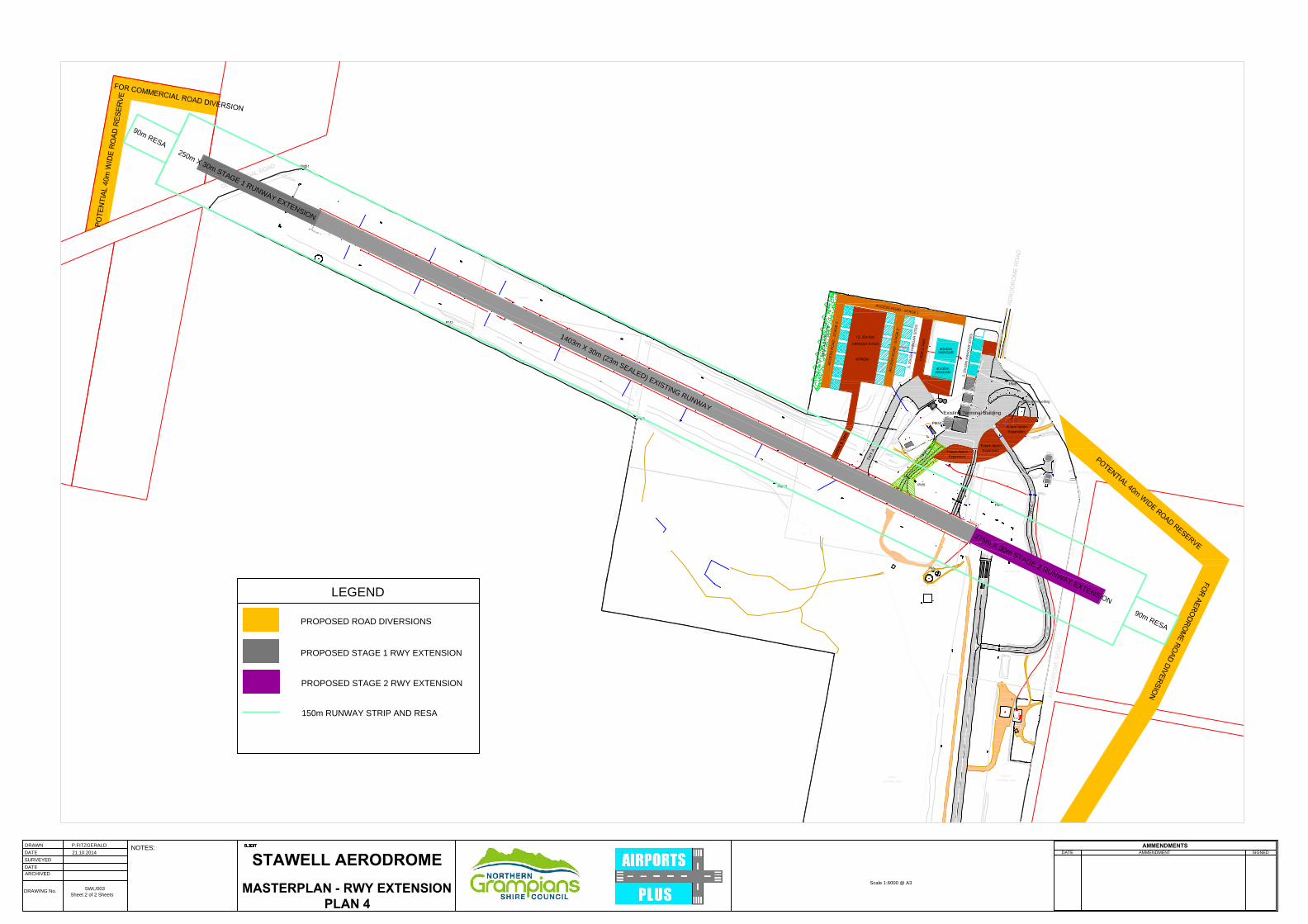
6.3 Runways The current length of Runway 11/29 is suitable for the range of aircraft expected to operate at Stawell Aerodrome over the next 5 – 10 years. Larger aircraft may commence operations at the aerodrome in the future. It is envisaged that these aircraft would be using the aerodrome as a maintenance base and therefore would only be operating with a minimum weight. If the size of fire suppression aircraft does increase it may be necessary to lengthen Runway 11/29 to cater for these aircraft types. It is possible to lengthen the runway in both directions if land was purchased at the western end and the existing road was realigned and an agreement was reached with GWMW allowing the eastern end to be extended into the land where the water treatment facility is located. The proposed extension would not impact on the existing lagoon. This runway extension would also require the road to be realigned that provides access to the DEPI fire base. A preliminary proposed layout of the runway is at Plan No. 4 which would provide a compliant runway with the MOS Part 139 - Aerodromes standards with a 90 m x 60 m RESA outside the runway strip. The runway extension at the western end is 250 m and the runway extension at the eastern end is 275 m giving a total runway length of approximately 1927 m. The runway surface would need to be widened to 30 m to ensure that the runway was fully Code 3 compliant. Planning and implementation of the runway extension could be undertaken in stages:
i. Purchase the land at the western end of the aerodrome.
ii. Reach agreement with GWMW on the use of their land for a future runway extension.
iii. Design runway extension including road realignment at the western end.
iv. Construct western extension, if required.
v. Design runway extension including road realignment at the eastern end.
vi. Construct eastern extension, if required.
The work to extend the runway would only commence if larger aircraft needed to operate from the aerodrome to ensure that fire protection of Western Victoria was not disadvantaged in the long term. The Obstacle Limitation Surfaces (OLS) associated with this runway meet the current standards in MOS Part 139 – Aerodromes. Two obstacle charts are available for Stawell Aerodrome; one chart is based on the proposed Runway 11/29 extensions. Runway 18/36 is not able to be extended due to physical constraints in the OLS, i.e. terrain.
Stawell Aerodrome
Airports Plus Pty Ltd Master Plan Review November 2014 Page 13
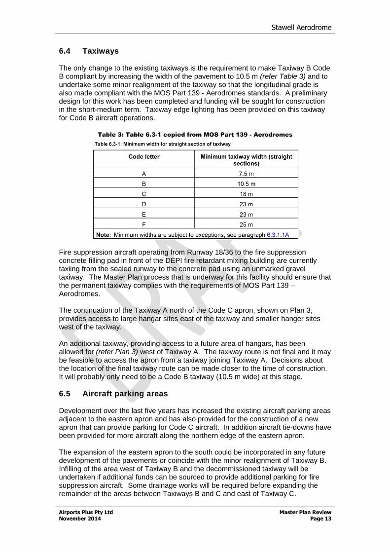
6.4 Taxiways The only change to the existing taxiways is the requirement to make Taxiway B Code B compliant by increasing the width of the pavement to 10.5 m (refer Table 3) and to undertake some minor realignment of the taxiway so that the longitudinal grade is also made compliant with the MOS Part 139 - Aerodromes standards. A preliminary design for this work has been completed and funding will be sought for construction in the short-medium term. Taxiway edge lighting has been provided on this taxiway for Code B aircraft operations.
Table 3: Table 6.3-1 copied from MOS Part 139 - Aerodromes
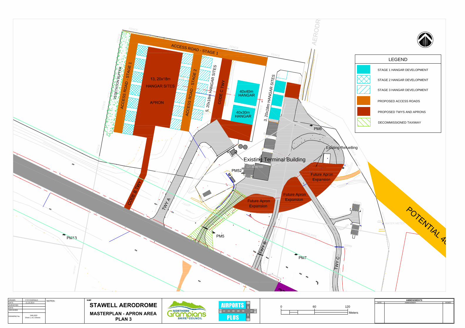
Fire suppression aircraft operating from Runway 18/36 to the fire suppression concrete filling pad in front of the DEPI fire retardant mixing building are currently taxiing from the sealed runway to the concrete pad using an unmarked gravel taxiway. The Master Plan process that is underway for this facility should ensure that the permanent taxiway complies with the requirements of MOS Part 139 – Aerodromes. The continuation of the Taxiway A north of the Code C apron, shown on Plan 3, provides access to large hangar sites east of the taxiway and smaller hanger sites west of the taxiway. An additional taxiway, providing access to a future area of hangars, has been allowed for (refer Plan 3) west of Taxiway A. The taxiway route is not final and it may be feasible to access the apron from a taxiway joining Taxiway A. Decisions about the location of the final taxiway route can be made closer to the time of construction. It will probably only need to be a Code B taxiway (10.5 m wide) at this stage.
6.5 Aircraft parking areas Development over the last five years has increased the existing aircraft parking areas adjacent to the eastern apron and has also provided for the construction of a new apron that can provide parking for Code C aircraft. In addition aircraft tie-downs have been provided for more aircraft along the northern edge of the eastern apron. The expansion of the eastern apron to the south could be incorporated in any future development of the pavements or coincide with the minor realignment of Taxiway B. Infilling of the area west of Taxiway B and the decommissioned taxiway will be undertaken if additional funds can be sourced to provide additional parking for fire suppression aircraft. Some drainage works will be required before expanding the remainder of the areas between Taxiways B and C and east of Taxiway C.
Stawell Aerodrome
Airports Plus Pty Ltd Master Plan Review November 2014 Page 14
Expansion of the Code C apron will be required to provide access to an approved new large hangar north of the Terminal. The construction of an additional large apron to service future hangars north of the proposed Code B taxiway will also provide additional aircraft pavement areas. The sequence of undertaking construction of expanded aircraft parking areas will depend entirely on whether there is a demand for parking of aircraft without associated hangars or if future tenants require hangar access for their aircraft. Due to practical constraints, i.e. earthworks, it may be more practicable to construct the most westerly line of hangars and associated taxiway in the first instance.
6.6 Future hangar development Significant hangar development is going to occur during the next twelve months. One 40 m x 30 m hangar has been approved and a second hangar 40 m x 40 m is in the planning process. Applications for smaller hangar sites are also being considered. Currently there are three hangar sites available for immediate occupancy. One further large hangar site will be available after earthworks have made the site level (Stage 1, Plan 3). An additional seven small hangar sites (Stage 2, Plan 3) could be made available on the western side of the aerodrome property with minimal earthworks involved. However, an access road would need to be constructed to provide access to these hangars. Future development of more hangar sites (Stage 3, Plan 3) would require major earthworks to fill the gully and dams that exist on this part of the aerodrome site. Over the last three years, clean fill has been continuously brought to the aerodrome from any work sites operated by the NGSC. This has enabled the Code C taxiway and apron, the Terminal and the large hangar site north of the Terminal to be developed. If this process continues there will eventually be sufficient fill available to level the development sites. A significant restraint is the need to remove native vegetation as under the new State planning requirements expensive additional vegetation offsets are required to replace any native vegetation removed. The remainder of the aerodrome site is currently Crown Land managed by NGSC. The area south of the DEPI complex is reserved for expansion of this facility and this area is used over summer for the short term parking of itinerant fixed wing and rotary wing aircraft that are on standby and are not Stawell Aerodrome fixed based operators. The forest area to the west of the aerodrome site has no development potential at the present time as access is restricted and the topography makes it unsuitable for development. Ownership of the forest area may be an asset in the longer term offsetting the carbon footprint of the aerodrome. It may also provide an opportunity to use this area to provide native vegetation offsets that will be required when native vegetation is removed for aerodrome development purposes.
6.7 Aviation fuel The installation of a new fuel facility that provides larger storage capacity and 24 hour access is expected to meet the requirements for aviation fuel for the life of this Master Plan Review.
Stawell Aerodrome
Airports Plus Pty Ltd Master Plan Review November 2014 Page 15
6.8 Vehicle access to the aerodrome Vehicle access has been greatly improved by the adoption of the 2009 Master Plan. The layout of internal roads was designed for vehicles, delivery trucks and customers to access all hangars and businesses without a need to enter the airside of the aerodrome. The placement of a physical barrier, between the roadways and the movement area has ensured that vehicles cannot enter the movement area via the gaps between the hangars. The road layout has also allowed for vehicle parking on either side of the road as new hangars are constructed. The access road layout can now continue to be implemented as hangar development occurs (refer Plan 3). Vehicle access to the Terminal precinct is via Aerodrome Road, Howells Road and Davidson Road. To provide better access to the most easterly hangar line for aircraft with a wingspan up to 24 m realignment of Aerodrome Road, where it runs parallel to the apron, should be considered in the medium - longer term. The road would need to be relocated approximately 25 m to the east to allow unrestricted access to the hangars by Code B aircraft. This realignment may require negotiations with GWMW to annex a small portion of their property for expansion of the road easement.
7 FUTURE AERODROME UTILITY REQUIREMENTS
7.1 Electricity Powercor has indicated that the existing power connection could be upgraded to 500 kVA with only minor works required. Currently, each hangar planned is restricted to a 40 amp supply from the distribution cabinet. If a larger supply is required then that would trigger the Powercor upgrade. There is no electricity supplied to the DEPI site and this is a separate matter for DEPI to resolve. There is no electricity available for the two most easterly hangars on the aerodrome site.
7.2 Water Water is supplied to the building area from a 40 mm AC water main that runs along the eastern boundary of the aerodrome site. DEPI has connected their site with a 50 mm poly pipe that enters their site from the south. This water main is connected to water storage tanks to ensure that there is adequate water for filling aircraft involved in fire suppression activities. An additional 100 mm water main has been laid between the storage tanks and the eastern apron to provide an additional location for filling aircraft. An upgraded water supply has been identified as being required so that greater volumes can be provided to both the DEPI and the aerodrome site. As the internal road system is developed provision is allowed for services including water to be installed.
7.3 Sewerage There is currently no sewerage connection to the aerodrome site. A new septic system has been installed to cater for the expansion of facilities over the last three years and has the capacity to accommodate further development over
Stawell Aerodrome
Airports Plus Pty Ltd Master Plan Review November 2014 Page 16
the next 5-10 years. As each new hangar line and access road is developed the sewerage lines will be incorporated in the service easement.
7.4 Telephone Telstra provides telephone lines onto the aerodrome site from a telephone main that runs along the western side of Aerodrome Road and terminates at a pillar located at the old access gate. The telephone main located on the western side of Aerodrome Road is only a ten pair cable but Telstra indicated that there was ample capacity to increase this line to a 50 pair cable. The demand for telephone services is not expected to exceed the available capacity in the next 10 – 15 years, and in any case the proposed new NBN should be connected within that time frame.
8 PLANNING CONTROLS
8.1 Planning update NGSC is in the process of updating the planning scheme for the aerodrome site. The Airport Environs Overlay (AEO) under the existing Planning Scheme is satisfactory for Stawell Aerodrome as it covers the area requiring protection for current and future aircraft types. Usually the AEO is based on the noise contours produced from a noise forecast but there is no requirement for a noise forecast to be produced for Stawell Aerodrome at this time. Council is currently undertaking a review of the AEO and should investigate the provision of a Design and Development Overlay (DDO) to ensure that future development does not infringe the current and future OLS and that inappropriate development does not occur that affects the published approach procedures in AIP-DAP, specifically the Runway 11/29 GNSS RNAV. Consideration of the implications on planning controls for the Runway 11/29 extensions should also be included in the current review. The controls in place to regulate future hangar development to ensure conformance with NGSC requirements should also be included in the current review. These controls could include the types of materials used to build hangars, their colour and alignment.
9 SUMMARY OF THE MASTER PLAN REVIEW The following is a summary of the Master Plan Review recommendations:
Continue the staged development of taxiways, aprons, hangars, utility requirements and internal access roads to meet ongoing demand.
Negotiate with land owners north of Runway 11/29 to trim trees that prevent the runway strip being published to a total width of 150 m.
Commence discussions regarding the requirements to extend Runway 11/29 in the future if larger fire suppression aircraft are required to be based at the aerodrome. Consider purchasing the land west of the aerodrome when it becomes available on the market to cater for a runway extension to the west.
Negotiate to acquire Crown Land that is zoned Public Use –Transport. Close the road reserves that cross the aerodrome site and convert the reserves to freehold land title.
Consolidate all land titles covering the aerodrome site held by NGSC onto one title.
Stawell Aerodrome
Airports Plus Pty Ltd Master Plan Review November 2014 Page 17
Prepare development guidelines for GA hangars so that the buildings are standardised to assist in orderly development on leased sites and to ensure the protection of access by taxiing aircraft.
Negotiate with GWMW to allow for the realignment of a section of Aerodrome Road, parallel with the proposed Stage 1 hangar development area, to provide suitable taxiway clearance for aircraft accessing the remaining development sites.
Discuss with GWMW the possibility of protecting the small area of land, located east of Runway 11/29, for the possible long-term extension of the runway. If GWMW agree then the possibility of extending the AEO to take account of this land should be investigated.
Review the Airport Environs Overlay to ensure future development does not restrict the use of the aerodrome and investigate the provision of a Design and Development Overlay to protect the current and future OLS and the published approach procedures.
9.1 Trigger points The following table indicates the expected trigger for the development of aviation facilities which are listed in the order of probable occurrence.
Facility Upgrade Trigger Point Timing
Upgrade Taxiway B to Code B standards as outlined in MOS Part 139 – Aerodromes, Chapter 6
To meet CASA compliance Immediate
Upgrade Taxiway C to Code A standards as outlined in MOS Part 139 – Aerodromes, Chapter 6
To meet CASA compliance Immediate
Complete animal proof fencing on the southern side of the aerodrome
Protection of aircraft operations (1 km/year)
Immediate
Prepare for Stage 2 and Stage 3 hangar and aircraft taxiing and parking areas, including internal access roads
Demand for hangar sites of various sizes
Next 1 - 3 years
Continue to upgrade utilities Dependent on hangar development and utility requirements
Ongoing
Acquisition of Crown Land or land swap
Ensure protection of aerodrome site for future development
Next 1 - 3 years
Consolidation of land titles to one title to assist with the management of the site
Ensure protection of the aerodrome site under the NGSC planning scheme
Next 2 - 4 years
Stawell Aerodrome
Airports Plus Pty Ltd Master Plan Review November 2014 Page 18
Trigger points cont’d
Facility Upgrade Trigger Point Timing
Consider extending Runway 11/29 to the west
Larger aircraft based at aerodrome requiring extra runway length
1 – 5 years
Consider extending Runway 11/29 to the east
Larger aircraft based at aerodrome requiring extra runway length
5 – 10 years
Stawell Aerodrome
Airports Plus Pty Ltd Master Plan Review November 2014 Page 19
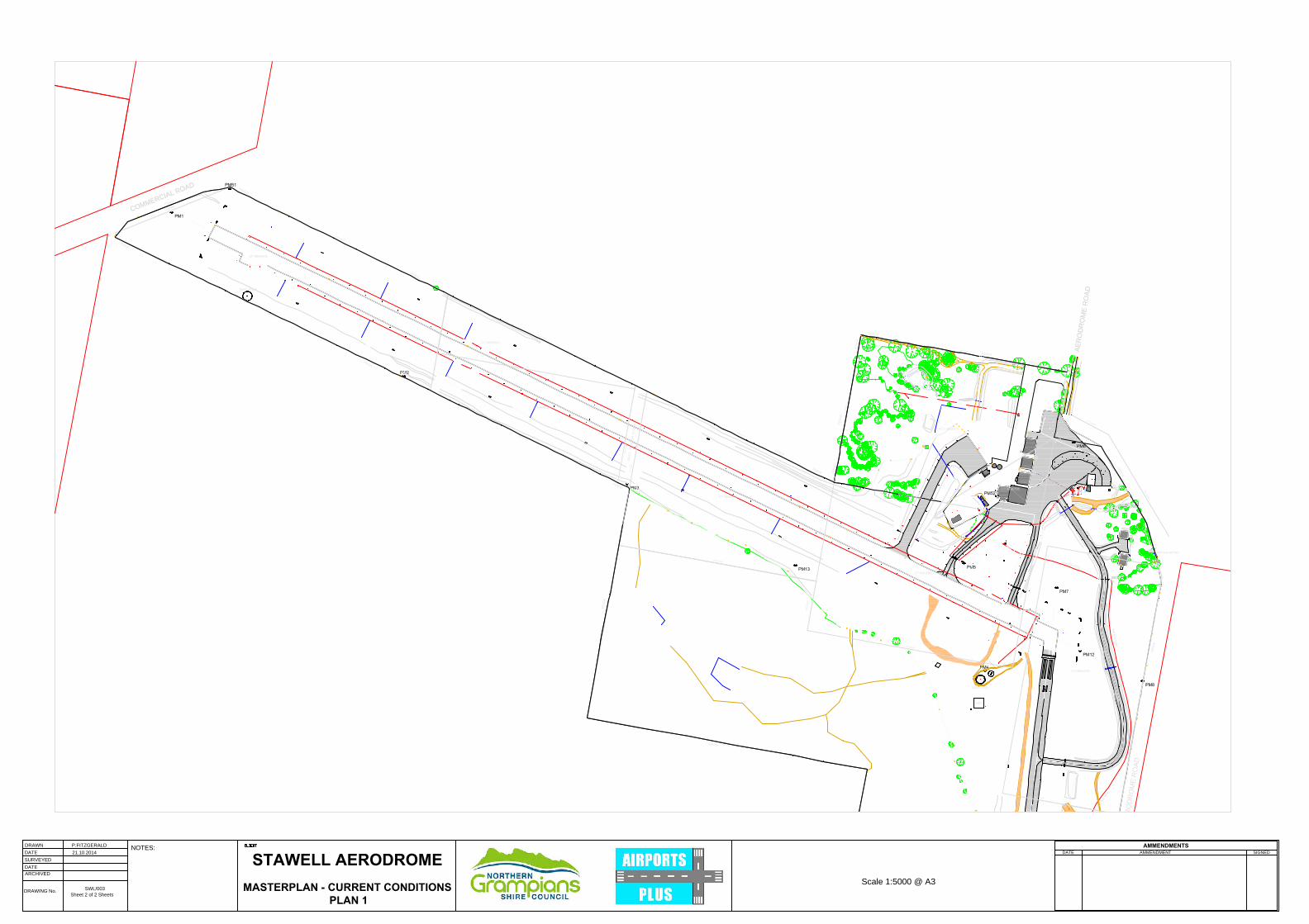
PLAN 1 – Current Aerodrome Layout
Stawell Aerodrome
Airports Plus Pty Ltd Master Plan November 2008 Version 2 Page 30
PLAN 2 – Crown Land v Council Land
Stawell Aerodrome
Airports Plus Pty Ltd Master Plan November 2008 Version 2 Page 32
PLAN 3 – Stages 1, 2 and 3 Hangar Development
Stawell Aerodrome
Airports Plus Pty Ltd Master Plan November 2008 Version 2 Page 34
PLAN 4 – Runway 11/29 possible extensions
C
O
M
M
E
R
C
I
A
L
R
O
A
D
A
E
R
O
D
R
O
M
E
R
O
A
D
WATER METER
WIND SOCK
MET
HELIPAD
F
E
N
C
E
F
E
N
C
E
F
E
N
C
E
F
E
N
C
E
F
E
N
C
E
F
E
N
C
E
F
E
N
C
E
F
E
N
C
E
F
E
N
C
E
F
E
N
C
E
F
E
N
C
E
F
E
N
C
E
F
E
N
C
E
F
E
N
C
E
C
O
M
M
E
R
C
I
A
L
R
O
A
D
A
E
R
O
D
R
O
M
E
R
O
A
D
F
E
N
C
E
F
E
N
C
E
F
E
N
C
E
F
E
N
C
E
2
9
6
°
0
3
'1
0
"
2
9
6
°
0
3
'1
0
"
1
0
°1
7
'
6
8
°
1
0
'4
0
"
1
1
6
°
0
3
'1
0
"
1
1
6
°
0
3
'1
0
"
1
9
0
°1
9
'4
0
"
1
1
6
°
0
3
'1
0
"
1
0
°2
1
'4
0
"
1
0
°1
9
'4
0
"
1
0
0
°2
0
'4
0
"
1
9
0
°2
0
'4
0
"
1
0
0
°2
0
'4
0
"
1
0
°2
0
'4
0
"
1
0
°1
8
'4
0
"
1
0
0
°3
9
'4
0
"
1
4
9
°
2
5
'
4
0
"
1
6
4
°
1
9
'4
0
"
2
8
0
°1
8
'4
0
"
1
9
0
°2
0
'4
0
"
1
0
0
°1
7
'4
0
"
1
0
°3
0
'4
0
"
2
8
0
°2
6
'4
0
"
1
0
°1
8
'4
0
"
6°37'20"
1
0
°1
8
'
1
0
0
°1
6
'2
0
"
1
9
0
°1
8
'4
0
"
1
1
7
°
4
2
'
4
0
"
1
4
9
°
2
5
'
4
0
"
F
E
N
C
E
F
E
N
C
E
F
E
N
C
E
F
E
N
C
E
A
E
R
O
D
R
O
M
E
R
O
A
D
A
C
C
E
S
S
R
O
A
D
A
C
C
E
S
S
R
O
A
D
C
O
D
E
C
T
W
Y
5
, 2
0
x
1
8
m
H
A
N
G
A
R
S
IT
E
S
40x40m
HANGAR
40x30m
HANGAR
3
, 2
0
x
1
8
m
H
A
N
G
A
R
S
IT
E
S
Future Apron
Expansion
Existing Terminal Building
Existing Refuelling
1
4
0
3
m
X
3
0
m
(
2
3
m
S
E
A
L
E
D
)
E
X
I
S
T
I
N
G
R
U
N
W
A
Y
2
5
0
m
X
3
0
m
S
T
A
G
E
1
R
U
N
W
A
Y
E
X
T
E
N
S
I
O
N
2
7
5
m
X
3
0
m
S
T
A
G
E
2
R
U
N
W
A
Y
E
X
T
E
N
S
I
O
N
9
0
m
R
E
S
A
9
0
m
R
E
S
A
A
C
C
E
S
S
R
O
A
D
- S
T
A
G
E
1
A
C
C
E
S
S
R
O
A
D
- S
T
A
G
E
2
A
C
C
E
S
S
R
O
A
D
- S
T
A
G
E
1
Future Apron
Expansion
Future Apron
Expansion
AMMENDMENTS
DATE AMMENDMENT SIGNED
STAWELL AERODROME
21.10.2014
P.FITZGERALD
Sheet 2 of 2 Sheets
SWL/003
DATE
DATE
DRAWN
SURVEYED
ARCHIVED
DRAWING No. MASTERPLAN - RWY EXTENSION
PLAN 4
NOTES:
LEGEND
PROPOSED ROAD DIVERSIONS
PROPOSED STAGE 1 RWY EXTENSION
PROPOSED STAGE 2 RWY EXTENSION
150m RUNWAY STRIP AND RESA
Scale 1:6000 @ A3
A
E
R
O
D
R
O
M
E
R
O
A
D
WATER METER
F
E
N
C
E
F
E
N
C
E
F
E
N
C
E
F
E
N
C
E
F
E
N
C
E
F
E
N
C
E
F
E
N
C
E
A
E
R
O
D
R
O
M
E
R
O
A
D
F
E
N
C
E
F
E
N
C
E
F
E
N
C
E
1
1
6
°
0
3
'1
0
"
1
0
°2
1
'4
0
"
1
9
0
°2
0
'4
0
"
1
0
°2
0
'4
0
"
1
0
°1
8
'4
0
"
1
0
0
°3
9
'4
0
"
1
4
9
°
2
5
'
4
0
"
1
6
4
°
1
9
'4
0
"
2
8
0
°1
8
'4
0
"
1
0
°1
8
'
1
0
0
°1
6
'2
0
"
1
9
0
°1
8
'4
0
"
1
1
7
°
4
2
'
4
0
"
1
4
9
°
2
5
'
4
0
"
F
E
N
C
E
F
E
N
C
E
A
C
C
E
S
S
R
O
A
D
A
C
C
E
S
S
R
O
A
D
C
O
D
E
C
T
W
Y
5
, 2
0
x
1
8
m
H
A
N
G
A
R
S
IT
E
S
40x40m
HANGAR
40x30m
HANGAR
3
, 2
0
x
1
8
m
H
A
N
G
A
R
S
IT
E
S
Future Apron
Expansion
Existing Terminal Building
Existing Refuelling
2
7
5
m
X
3
0
m
S
T
A
G
E
2
R
U
N
W
A
Y
E
X
T
E
N
S
I
O
N
A
C
C
E
S
S
R
O
A
D
- S
T
A
G
E
1
A
C
C
E
S
S
R
O
A
D
- S
T
A
G
E
2
A
C
C
E
S
S
R
O
A
D
- S
T
A
G
E
1
Future Apron
Expansion
Future Apron
Expansion
AMMENDMENTS
DATE AMMENDMENT SIGNED
STAWELL AERODROME
21.10.2014
P.FITZGERALD
Sheet 1 of 2 Sheets
SWL/003
DATE
DATE
DRAWN
SURVEYED
ARCHIVED
DRAWING No.
MASTERPLAN - APRON AREA
PLAN 3
NOTES:
Meters
0 60 120
LEGEND
STAGE 1 HANGAR DEVELOPMENT
PROPOSED ACCESS ROADS
PROPOSED TWYS AND APRONS
DECOMMISSIONED TAXIWAY
STAGE 2 HANGAR DEVELOPMENT
STAGE 3 HANGAR DEVELOPMENT
C
O
M
M
E
R
C
I
A
L
R
O
A
D
A
E
R
O
D
R
O
M
E
R
O
A
D
WATER METER
WIND SOCK
MET
F
E
N
C
E
F
E
N
C
E
F
E
N
C
E
F
E
N
C
E
F
E
N
C
E
F
E
N
C
E
F
E
N
C
E
F
E
N
C
E
F
E
N
C
E
F
E
N
C
E
F
E
N
C
E
F
E
N
C
E
F
E
N
C
E
C
O
M
M
E
R
C
I
A
L
R
O
A
D
A
E
R
O
D
R
O
M
E
R
O
A
D
F
E
N
C
E
F
E
N
C
E
F
E
N
C
E
F
E
N
C
E
2
9
6
°
0
3
'1
0
"
2
9
6
°
0
3
'
1
0
"
1
0
°1
7
'
6
8
°
1
0
'4
0
"
1
1
6
°
0
3
'1
0
"
1
1
6
°
0
3
'1
0
"
1
9
0
°1
9
'4
0
"
1
1
6
°
0
3
'1
0
"
1
0
°2
1
'4
0
"
1
0
°1
9
'4
0
"
1
0
0
°2
0
'4
0
"
1
9
0
°2
0
'4
0
"
1
0
0
°2
0
'4
0
"
1
0
°2
0
'4
0
"
1
0
°1
8
'4
0
"
1
0
0
°3
9
'4
0
"
1
4
9
°
2
5
'
4
0
"
1
6
4
°
1
9
'4
0
"
2
8
0
°1
8
'4
0
"
1
9
0
°2
0
'4
0
"
1
0
0
°1
7
'4
0
"
2
8
0
°2
6
'4
0
"
1
0
°1
8
'4
0
"
1
0
°1
8
'
1
0
0
°1
6
'2
0
"
1
9
0
°1
8
'4
0
"
1
1
7
°
4
2
'
4
0
"
1
4
9
°
2
5
'
4
0
"
F
E
N
C
E
F
E
N
C
E
F
E
N
C
E
F
E
N
C
E
A
E
R
O
D
R
O
M
E
R
O
A
D
AMMENDMENTS
DATE AMMENDMENT SIGNED
STAWELL AERODROME
21.10.2014
P.FITZGERALD
Sheet 2 of 2 Sheets
SWL/003
DATE
DATE
DRAWN
SURVEYED
ARCHIVED
DRAWING No.
MASTERPLAN - CURRENT CONDITIONS
PLAN 1
NOTES:
Scale 1:5000 @ A3