status update for the albany hts cable project · status update for the albany hts cable project...
TRANSCRIPT
Status Update for the Albany HTS Cable Project
Chuck Weber, SuperPower, Inc.Shigeki Isojima, Sumitomo Electric Industries
HTS Solutions for a New Dimension in PowerSuperconductivity for Electric Systems – 2007 Annual DOE Peer Review – August 7-9, 2007

2007 DOE Peer Review – 1 –
Presentation Outline
• Program Outline & Objectives• Background information on the Albany Cable Project
• FY2007 Milestones
• FY2007 Accomplishments & Results
• FY08 Planned Performance & Milestones
• Technology Transfer, Collaborations & Partnerships
• Summary

2007 DOE Peer Review – 2 –
Program Overview
• 350m long - 34.5kV - 800Arms - 48MVA
• Cold dielectric, 3 phases-in-1 cryostat, stranded copper core design
Project Manager; Site infrastructure, Manufacture of 2G HTS wire
Host utility, conventional cable & system protection, system impact studies
Design, build, install, and test the HTS cable, terminations, & joint
Design, construct and operate the Cryogenic Refrigeration System, and provide overall cable remote monitoring and utility interfaceSupported by Federal (DOE) and NY State (NYSERDA) Funds

2007 DOE Peer Review – 3 –
Site Location
Phase II: 30m YBCO
Phase I: BSCCO
2007 DOE Peer Review – 4 –
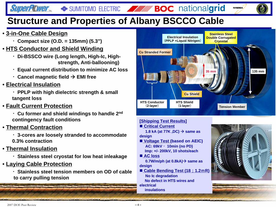
• 3-in-One Cable Design・Compact size (O.D. = 135mm) (5.3”)
• HTS Conductor and Shield Winding・Di-BSSCO wire (Long length, High-Ic, High-
strength, Anti-ballooning)・Equal current distribution to minimize AC loss ・Cancel magnetic field EMI free
• Electrical Insulation・PPLP with high dielectric strength & small tangent loss
• Fault Current Protection・Cu former and shield windings to handle 2nd
contingency fault conditions• Thermal Contraction
・3-cores are loosely stranded to accommodate0.3% contraction
• Thermal Insulation・Stainless steel cryostat for low heat inleakage
• Laying Cable Protection・Stainless steel tension members on OD of cableto carry pulling tension
[Shipping Test Results] Critical Current1.8 kA (at 77K ,DC) same as
designVoltage Test (based on AEIC) AC: 69kV ・10min (no PD)Imp: +/- 200kV, 10 shots/eachAC loss0.7W/m/ph (at 0.8kA) same as
designCable Bending Test (18;1.2mR)No Ic degradationNo defect in HTS wires and
electrical insulations
Structure and Properties of Albany BSCCO Cable
HTS Conductor(2-layer)
HTS Shield(1-layer)
Cu Shield
135 mm35 mm
Electrical Insulation(PPLP +Liquid Nitrigen)
Cu Stranded Former
Tension Member
Stainless Steel Double Corrugated
Cryostat
HTS Conductor(2-layer)
HTS Shield(1-layer)
Cu Shield
135 mm35 mm
Electrical Insulation(PPLP +Liquid Nitrigen)
Cu Stranded Former
Tension Member
Stainless Steel Double Corrugated
Cryostat

2007 DOE Peer Review – 5 –
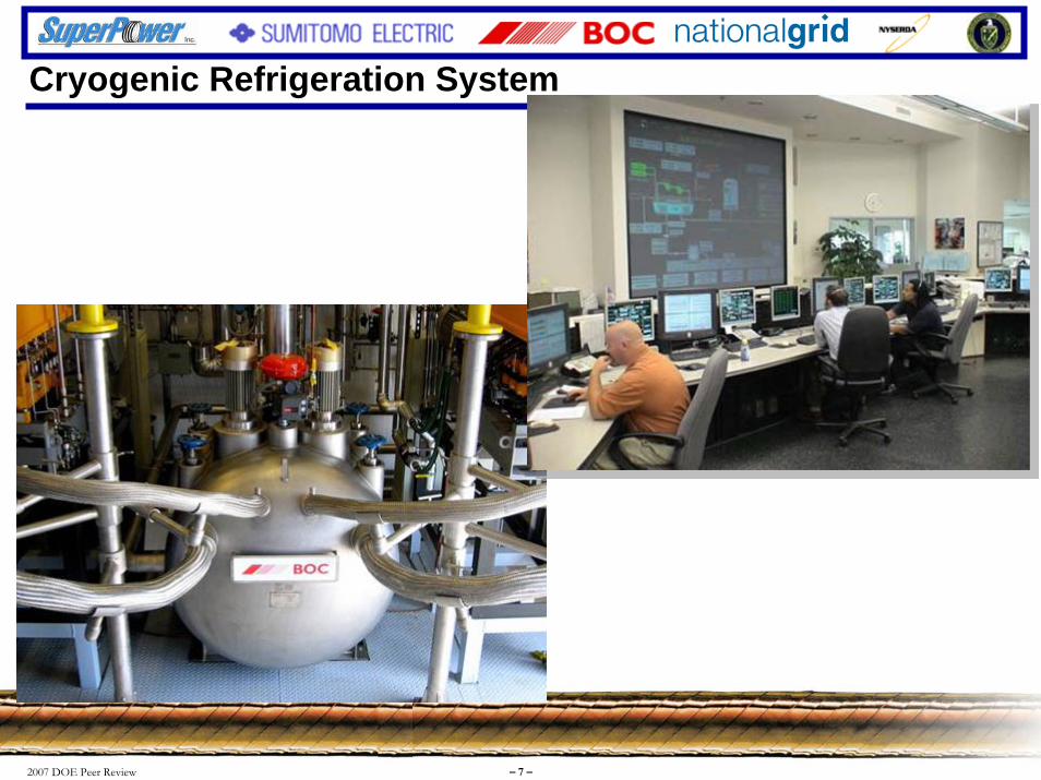
Cryogenic Refrigeration System: Approach
Cryocooler
Thermosyphon
Liquid NitrogenStorage/buffer
Subcooled liquid nitrogen loop
HTS cable
Hybrid arrangement permits transparent use of bulk liquid nitrogen for back-up
Thermosyphon provides common heat exchange interface between cable and open or closed refrigeration sources

2007 DOE Peer Review – 6 –
Cryogenic Refrigeration System
Item Specification
Coolant supply tem perature 67 to 77 KTem perature stability +-0.1 K - norm al operation
+-1.0 K - backup operationRefrigeration capacity 5 kW at 77 K
3.7 kW at 70 KM inim um coolant pressure 1 to 5 barg +-0.2M axim um coolant flow rate 50 liter/m in +-1
(excluding CRS)
1.4 m
1.6 m
BOC
2007 DOE Peer Review – 7 –
Cryogenic Refrigeration System

2007 DOE Peer Review – 8 –
Cryogenic Refrigeration System

2007 DOE Peer Review – 9 –
Phase I Installation
Cable Installation• Tension : max. 2ton• No cable elongation• No vacuum leakageConventional methods used to install HTS cable

2007 DOE Peer Review – 10 –
-200
-150
-100
-50
0
50
0 50 100 150 200 250 300 350 400
Cable Length [m]
Tem
pera
ture
[ ℃]
SouthTerm.
0 H
12 H16H
20 H24H
28H34H 2D
3D
9.2D
11.5D 11.6D 11.7D 11.8D 12D 12.4D
0 50 100 150 200 250 300 350
NorthTerm.
Test Items Test Results
System withstand pressure Test 0.61 MPaG (based on ASME code): good
Maximum core tension: approx. 800kgTension minimized by “loosely stranded 3-core structure”
Vacuum level at each part: good (no leakage)Core behavior inside the joint: within the scope of design
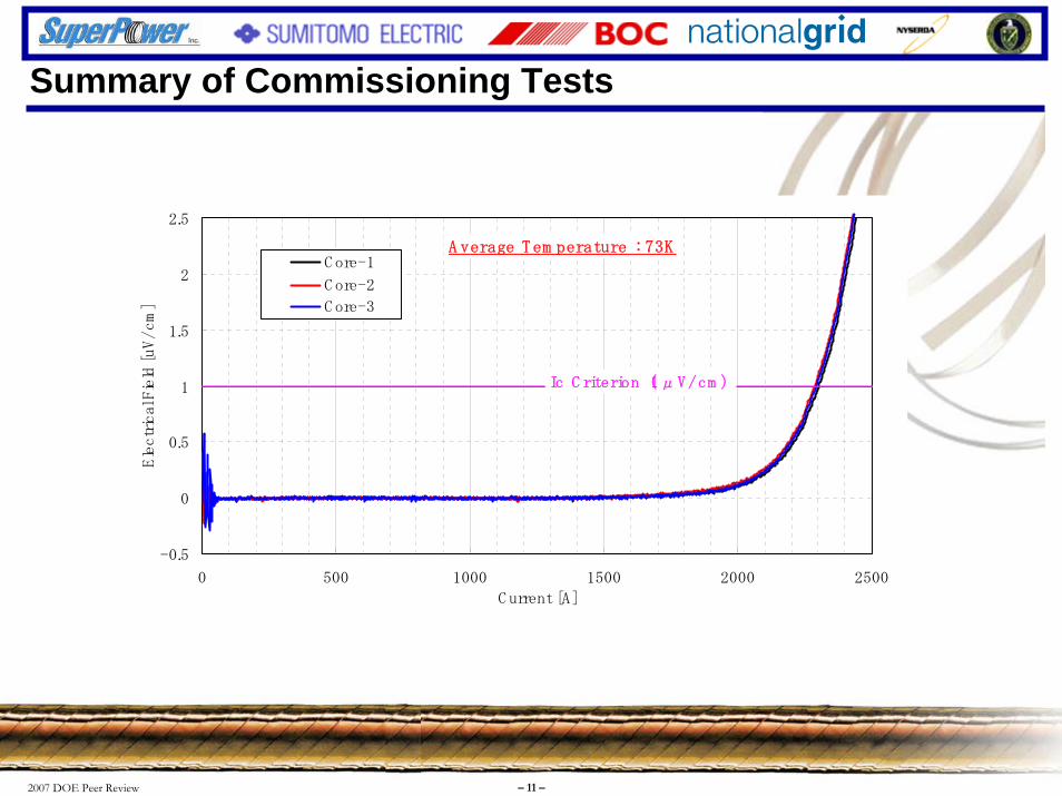
2.3kA (dc, defined at 1uV/cm) at 73K Same as the design value
350 m cable section (including joint) : 1.0kWEntire cable system (not including CRS) : 3.1kW
350 m cable section (including joint) : 0.075 MPaclosely matches with the design value (0.07 MPa)
100 kV, 5 minutes, each phase (based on AEIC standard) : good
Initial cooling test
Critical current measurement
Heat loss measurement(under no-load condition)
Pressure drop measurement (Flow rate:50L/min)
DC withstand voltage test
-0.5
0
0.5
1
1.5
2
2.5
0 500 1000 1500 2000 2500
C urrent [A]
Electrical Field [uV/cm]
C ore-1
C ore-2
C ore-3
Ic C riterion(1μV/cm )
A verage Tem perature : 73K
Summary of Commissioning Tests
2007 DOE Peer Review – 11 –
Summary of Commissioning Tests
-0.5
0
0.5
1
1.5
2
2.5
0 500 1000 1500 2000 2500
C urrent [A]
Electrical Field [uV/cm]
C ore-1
C ore-2
C ore-3
Ic C riterion(1μV/cm )
A verage Tem perature : 73K
2007 DOE Peer Review – 12 –
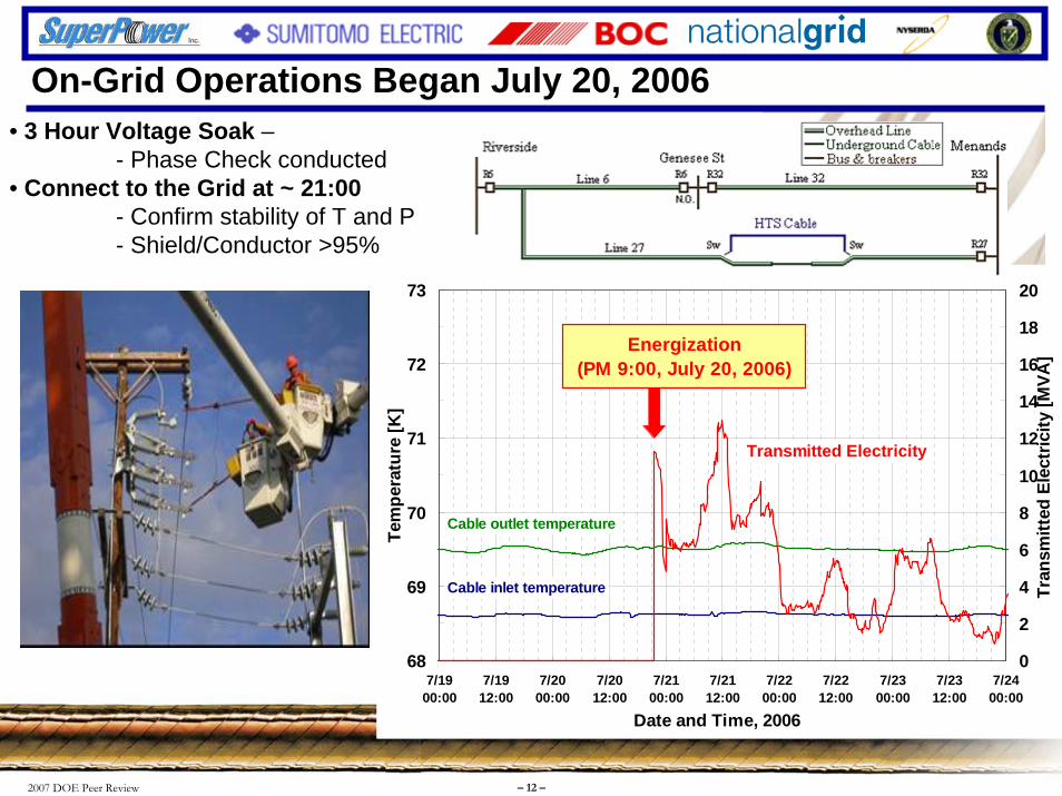
• 3 Hour Voltage Soak –- Phase Check conducted
• Connect to the Grid at ~ 21:00- Confirm stability of T and P- Shield/Conductor >95%
On-Grid Operations Began July 20, 2006
68
69
70
71
72
73
7/1900:00
7/1912:00
7/2000:00
7/2012:00
7/2100:00
7/2112:00
7/2200:00
7/2212:00
7/2300:00
7/2312:00
7/2400:00
Date and Time, 2006
Tem
pera
ture
[K]
0
2
4
6
8
10
12
14
16
18
20
Tran
smitt
ed E
lect
ricity
[MVA
]
Cable inlet temperature
Cable outlet temperature
Transmitted Electricity
Energization(PM 9:00, July 20, 2006)

2007 DOE Peer Review – 13 –
Presentation Outline
• Program Outline & Objectives• Background information on the Albany Cable Project
• FY2007 Milestones
• FY2007 Accomplishments & Results
• FY08 Planned Performance & Milestones
• Technology Transfer, Collaborations & Partnerships
• Summary

2007 DOE Peer Review – 14 –
FY2007 Objectives
The primary objectives for FY2007:
Phase I
1. Monitor and operate Phase I of the cable system remotely from the BOC Remote Operations Center (ROC) for a minimum of 6 months
Phase II
2. Complete the cable design for the YBCO cable
3. Complete fabrication of YBCO wire for the 30 m Phase 2 cable
4. Complete fabrication and factory testing of the 30 m YBCO cable
5. Commence installation of the 30 m YBCO cable
2007 DOE Peer Review – 15 –
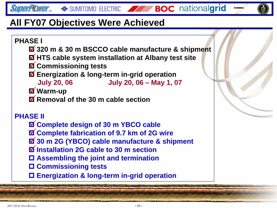
PHASE I320 m & 30 m BSCCO cable manufacture & shipmentHTS cable system installation at Albany test site Commissioning testsEnergization & long-term in-grid operation
Warm-up Removal of the 30 m cable section
PHASE IIComplete design of 30 m YBCO cableComplete fabrication of 9.7 km of 2G wire30 m 2G (YBCO) cable manufacture & shipmentInstallation 2G cable to 30 m sectionAssembling the joint and termination Commissioning testsEnergization & long-term in-grid operation
July 20, 06 – May 1, 07July 20, 06
Current Status of Albany Project
All FY07 Objectives Were Achieved
2007 DOE Peer Review – 16 –
Presentation Outline
• Program Outline & Objectives• Background information on the Albany Cable Project
• FY2007 Milestones
• FY2007 Accomplishments & Results
• FY08 Planned Performance & Milestones
• Technology Transfer, Collaborations & Partnerships
• Summary
2007 DOE Peer Review – 17 –
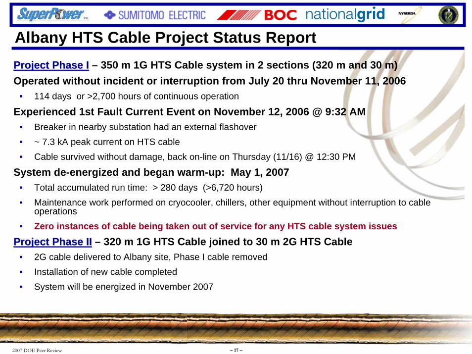
Albany HTS Cable Project Status ReportProject Phase IProject Phase I – 350 m 1G HTS Cable system in 2 sections (320 m and 30 m)Operated without incident or interruption from July 20 thru November 11, 2006
• 114 days or >2,700 hours of continuous operation
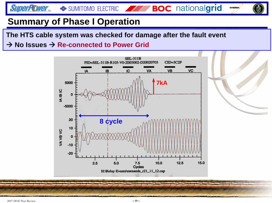
Experienced 1st Fault Current Event on November 12, 2006 @ 9:32 AM• Breaker in nearby substation had an external flashover• ~ 7.3 kA peak current on HTS cable• Cable survived without damage, back on-line on Thursday (11/16) @ 12:30 PM
System de-energized and began warm-up: May 1, 2007 • Total accumulated run time: > 280 days (>6,720 hours)• Maintenance work performed on cryocooler, chillers, other equipment without interruption to cable
operations• Zero instances of cable being taken out of service for any HTS cable system issues
Project Phase IIProject Phase II – 320 m 1G HTS Cable joined to 30 m 2G HTS Cable• 2G cable delivered to Albany site, Phase I cable removed• Installation of new cable completed• System will be energized in November 2007

2007 DOE Peer Review – 18 –
66
67
68
69
70
71
7/20 8/17 9/14 10/12 11/9 12/7 1/4 2/1 3/1 3/29 4/26
Date (2006-2007)
Tem
pera
ture
[K]
0
4
8
12
16
20
Tran
smitt
ed E
lect
ricity
[MVA
]
Cable Inlet Temperature
Cable Outlet Temperature
Transmitted Electricity
Chiller System ShutdownSupply Voltage Issue
Energizedon July 20,2006
Completedon May 1, 2007
Fault Current Event
More Than 6,700 Hrs of Reliable Power Transmission
Summary of Phase I Operation
2007 DOE Peer Review – 19 –
7kA
8 cycle
The HTS cable system was checked for damage after the fault eventNo Issues Re-connected to Power Grid
Summary of Phase I Operation
2007 DOE Peer Review – 20 –
-200
-150
-100
-50
0
50
0 100 200 300 400 500 600 700 800Position [m]
Tem
pera
ture
[ ℃]
30m HTS Cable320m HTS Cable
350m Return Pipe
12H
1D
3D
5D
7D
9D
11D
14D
21D
SouthTerm
NorthTerm
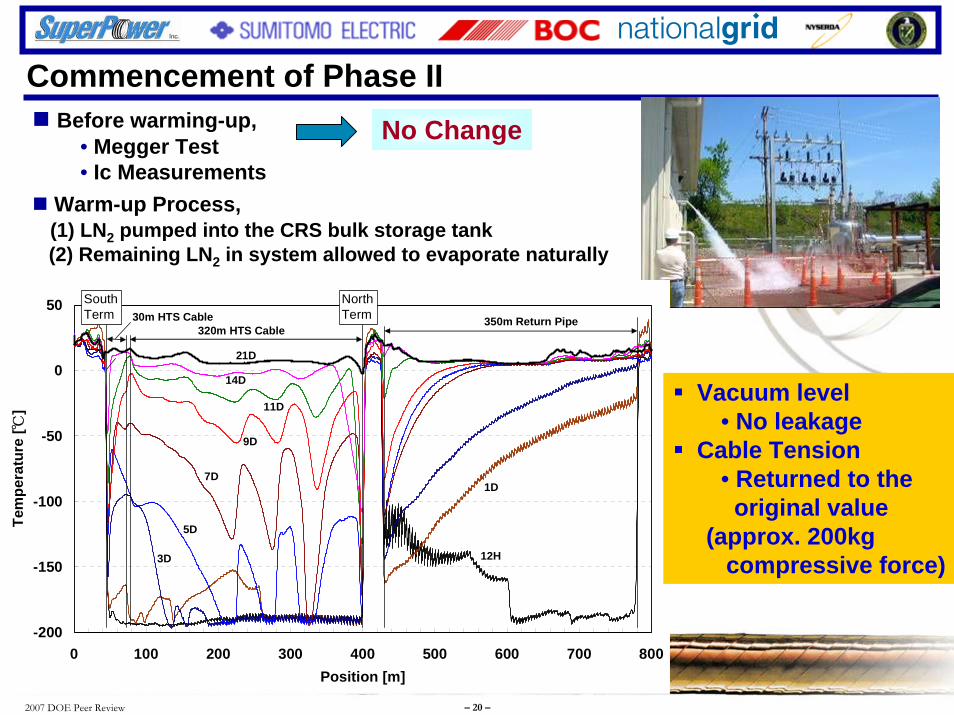
Before warming-up,• Megger Test• Ic Measurements
Warm-up Process,(1) LN2 pumped into the CRS bulk storage tank(2) Remaining LN2 in system allowed to evaporate naturally
No Change
Vacuum level• No leakage
Cable Tension• Returned to theoriginal value
(approx. 200kgcompressive force)
Commencement of Phase II
2007 DOE Peer Review – 21 –
Design of YBCO Cable (3-in-One Type)
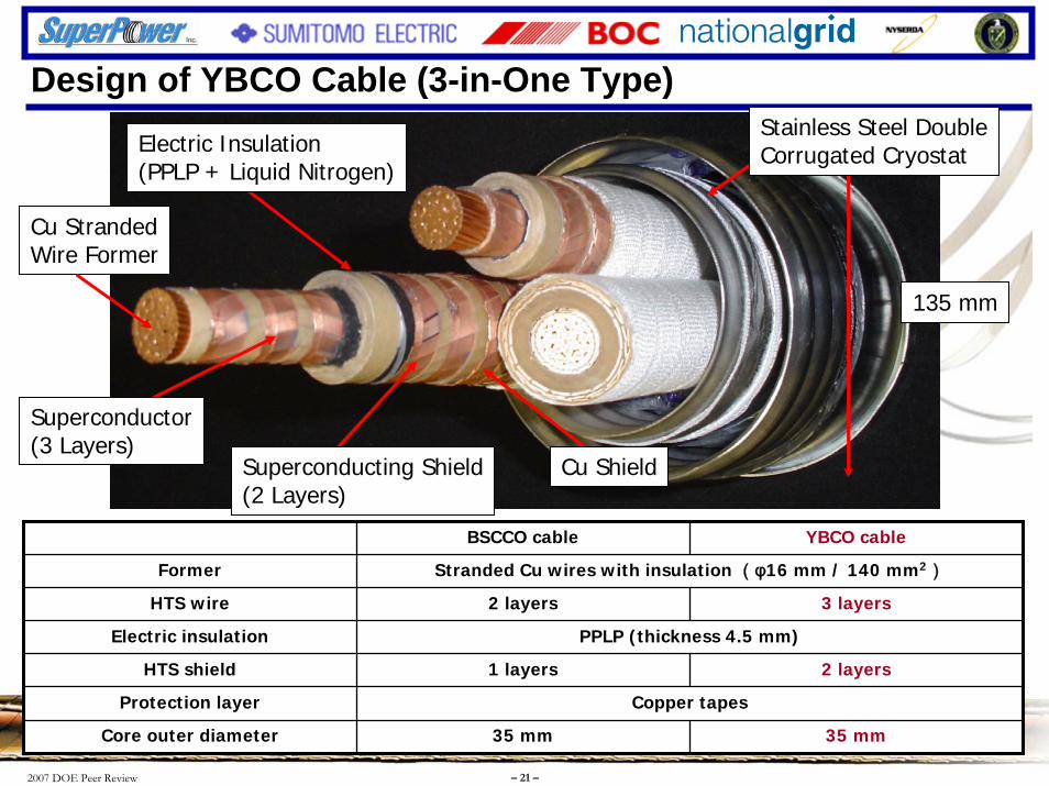
BSCCO cable YBCO cable
HTS wire 2 layers 3 layers
Former Stranded Cu wires with insulation (φ16 mm / 140 mm2)
Electric insulation PPLP (thickness 4.5 mm)
HTS shield 1 layers 2 layers
Protection layer Copper tapes
Core outer diameter 35 mm 35 mm
Cu StrandedWire Former
Electric Insulation(PPLP + Liquid Nitrogen)
Stainless Steel DoubleCorrugated Cryostat
Cu ShieldSuperconducting Shield(2 Layers)
Superconductor(3 Layers)
135 mm
2007 DOE Peer Review – 22 –
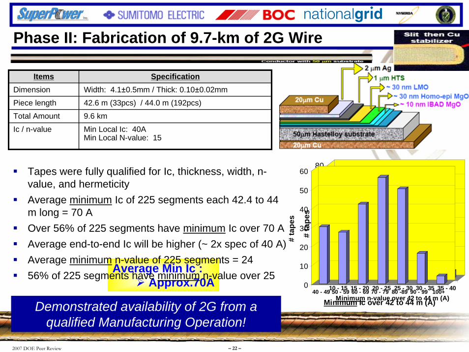
Items SpecificationDimension Width: 4.1±0.5mm / Thick: 0.10±0.02mm
Piece length 42.6 m (33pcs) / 44.0 m (192pcs)
Total Amount 9.6 km
Ic / n-value Min Local Ic: 40AMin Local N-value: 15
Average Min Ic :Approx.70A
Tapes were fully qualified for Ic, thickness, width, n-value, and hermeticityAverage minimum
Phase II: Fabrication of 9.7-km of 2G Wire
Ic of 225 segments each 42.4 to 44 m long = 70 A Over 56% of 225 segments have minimum Ic over 70 AAverage end-to-end Ic will be higher (~ 2x spec of 40 A)Average minimum n-value of 225 segments = 24 56% of 225 segments have minimum n-value over 25
Demonstrated availability of 2G from a qualified Manufacturing Operation!
0
10
20
30
40
50
60
70
80
# ta
pes
10 - 15 15 - 20 20 - 25 25 - 30 30 - 35 35 - 40Minimum n-value over 42 to 44 m (A)
0
10
20
30
40
50
60
# ta
pes
40 - 49 50 - 59 60 - 69 70 - 79 80 -89 90 - 99 100+
Minimum Ic over 42 to 44 m (A)

2007 DOE Peer Review – 23 –
10 m Test Cable Fabrication with 2G WireConductor Layer Shielding Layer
Good winding performance without any Ic degradation
2007 DOE Peer Review – 24 –
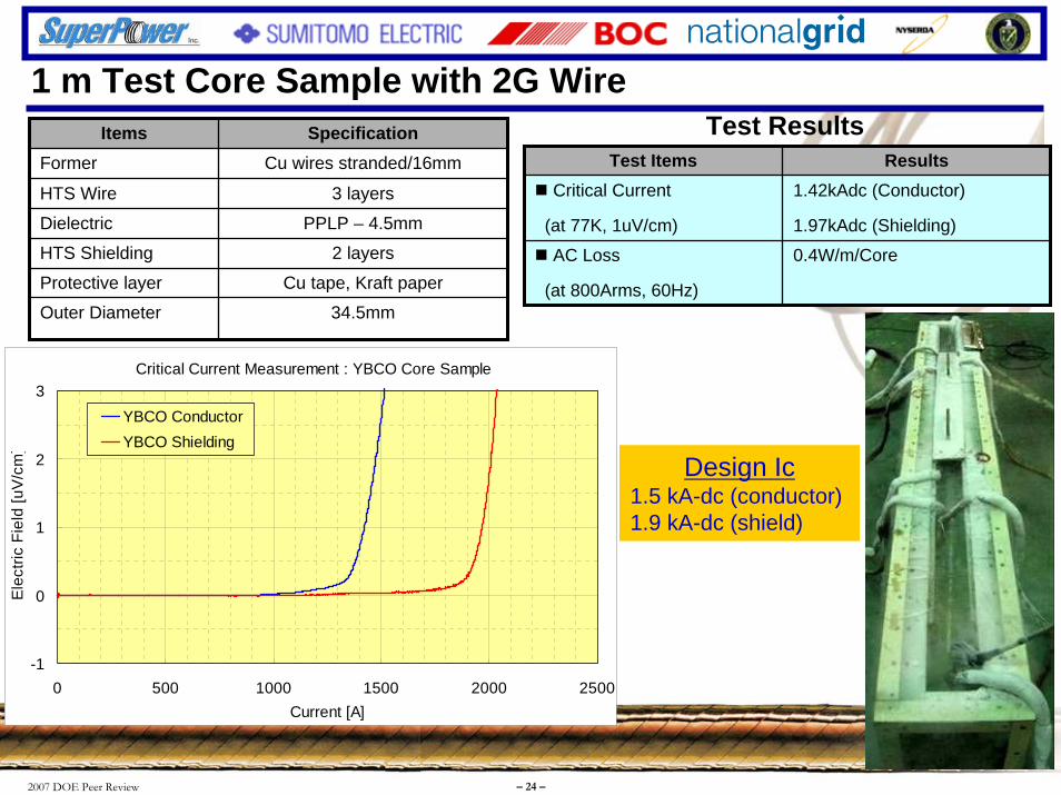
1 m Test Core Sample with 2G WireItems Specification
Former Cu wires stranded/16mm
HTS Wire 3 layers
Dielectric PPLP – 4.5mm
HTS Shielding 2 layers
Protective layer Cu tape, Kraft paper
Outer Diameter 34.5mm
Critical Current Measurement : YBCO Core Sample
-1
0
1
2
3
0 500 1000 1500 2000 2500Current [A]
Ele
ctric
Fie
ld [u
V/cm
]
YBCO ConductorYBCO Shielding
Test Items ResultsCritical Current
(at 77K, 1uV/cm)
1.42kAdc (Conductor)
1.97kAdc (Shielding)
AC Loss
(at 800Arms, 60Hz)
0.4W/m/Core
Test Results
Design Ic1.5 kA-dc (conductor)1.9 kA-dc (shield)

2007 DOE Peer Review – 25 –
Fault Current Test with 1 m 2G Sample CableFault Current Testing• Sample: BSCCO Core – YBCO Core
(Compare YBCO core with BSCCO one) • Current: 23kA• Duration: 8 – 38cycles• Cooling: Open Bath (77K)
Test Site : Nissin Electric (Kyoto)
0
10
20
30
40
50
60
70
80
90
100
0 10 20 30 40 50Duration [cycles, 60Hz]
Max
imum
Tem
pera
ture
Ris
e [K
]
BSCCO ConductorBSCCO ShieldYBCO ConductorYBCO Shield
Shield
Conductor
Generator(5000V)
Lg
L1 L2 L0Transformer(6600V/550V)
Test SamplesSWGenerator(5000V)
Lg
L1 L2 L0Transformer(6600V/550V)
Test SamplesSW
Temperature Rise During Faultnearly identical to BSCCO core

2007 DOE Peer Review – 26 –
[YBCO tape winding process] [3 cores stranding process]
YBCO cable was fabricated under nearly the same conditions as the BSCCO cable
Fabrication of the 30 m YBCO Cable
2007 DOE Peer Review – 27 –
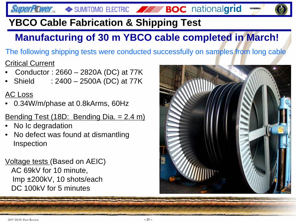
Manufacturing of 30 m YBCO cable completed in March!
Critical Current• Conductor : 2660 – 2820A (DC) at 77K• Shield : 2400 – 2500A (DC) at 77K
AC Loss• 0.34W/m/phase at 0.8kArms, 60Hz
Bending Test (18D: Bending Dia. = 2.4 m)• No Ic degradation• No defect was found at dismantling
Inspection
Voltage tests (Based on AEIC)AC 69kV for 10 minute, Imp ±200kV, 10 shots/eachDC 100kV for 5 minutes
The following shipping tests were conducted successfully on samples from long cable
YBCO Cable Fabrication & Shipping Test

2007 DOE Peer Review – 28 –
-0.5
0
0.5
1
1.5
2
0 500 1000 1500 2000 2500 3000Current (A, DC)
Elec
trica
l Fie
ld(u
V/cm
)
Core-1Core-2Core-3
Ic Criterion (1uV/cm)
-0.5
0
0.5
1
1.5
2
0 500 1000 1500 2000 2500 3000Current (A, DC)
Elec
trica
l Fie
ld(u
V/cm
)
Core-1Core-2Core-3
Ic Criterion (1uV/cm)
Sample: 3 meter 3-Core
Ic (Conductor) = Approx. 2660 – 2820A (DC, 77K, 1uV/cm)
Ic (Shield) = Approx. 2400 – 2500A (DC, 77K, 1uV/cm)
Conductor Shield
Very good match between test results and design values
Critical Current Measurement
2007 DOE Peer Review – 29 –
0.001
0.01
0.1
1
100 1000 10000Loading Current (Arms, 60Hz)
AC
loss
(W/m
/pha
se)
Measured value
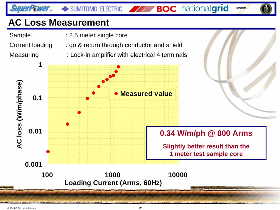
Sample : 2.5 meter single coreCurrent loading : go & return through conductor and shieldMeasuring : Lock-in amplifier with electrical 4 terminals
0.34 W/m/ph @ 800 ArmsSlightly better result than the
1 meter test sample core
AC Loss Measurement
2007 DOE Peer Review – 30 –
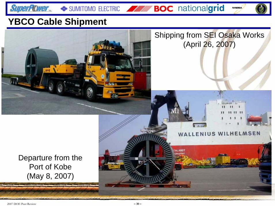
YBCO Cable Shipment
Departure from the Port of Kobe
(May 8, 2007)
Shipping from SEI Osaka Works (April 26, 2007)
2007 DOE Peer Review – 31 –
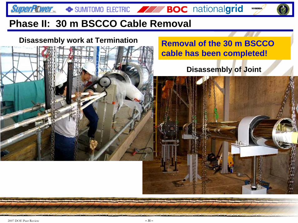
Disassembly of Joint
Disassembly work at Termination Removal of the 30 m BSCCO cable has been completed!
Phase II: 30 m BSCCO Cable Removal

2007 DOE Peer Review – 32 –
Installation of 30 m YBCO Cable

2007 DOE Peer Review – 33 –
FY2007 Objectives:The primary objectives for FY2007:
Monitor and operate Phase I of the cable system remotely from the BOC Remote Operations Center (ROC) for a minimum of 6 months
Phase I operated for >9 months with no outages due to issues related to the HTS system
Complete the cable design for the YBCO cable
Slight alterations from BSCCO cable design incorporated into YBCO cable design
Complete fabrication of YBCO wire for the 30 m Phase 2 cable
9.7 km of 2G wire fabricated and tested last fall
Complete fabrication and factory testing of the 30 m YBCO cable
30 m YBCO cable fabricated and passed all FAT by March 07
Commence installation of the 30 m YBCO cable
Phase II began on May 1, YBCO cable installed and being connected

2007 DOE Peer Review – 34 –
Presentation Outline
• Program Outline & Objectives• Background information on the Albany Cable Project
• FY2007 Milestones
• FY2007 Accomplishments & Results
• FY08 Planned Performance & Milestones
• Technology Transfer, Collaborations & Partnerships
• Summary
2007 DOE Peer Review – 35 –
FY 2008 Plans
Complete installation and pre-commissioning testing of the YBCO/BSCCO cable
Complete the cooldown process of the cable system and begin online operation of Phase II
Monitor and operate the cable system throughout GFY08
Additional Items
Push stakeholders to support longer term on-grid operation
Continue promotion and technology transfer of HTS cable technology
Continue support for the HTS Cable Collaborative

2007 DOE Peer Review – 36 –
Presentation Outline
• Program Outline & Objectives• Background information on the Albany Cable Project
• FY2007 Milestones
• FY2007 Accomplishments & Results
• FY08 Planned Performance & Milestones
• Technology Transfer, Collaborations & Partnerships
• Summary
2007 DOE Peer Review – 37 –
Technology Transfer, Collaborations & PartnershipsPresentations• ASC ’06 – Seattle, WA – 8/28-9/1/06
• EPRI S/C Workshop – Columbus, OH 9/13-14/06
• Tech Valley Chamber Executive Institute –10/22/06
• Leadership Tech Valley Group – 10/23/06
• DOE Wire Workshop – Panama City, FL 1/16-17/2007
• IEEE Schenectady Chapter – 1/19/07
• HTS Cable Collaborative Meetings
• IEEE PES General Meeting – Tampa, FL–6/25-28/07
• ISIS-15 (Erlangen, Germany) – 9/27-29/06
• N
• K– 1
• D(Nashville, TN) –
• S
• Q
• N(Washington, DC) –
• H2007
• R
• C
o. Colonie HS Technology Night – 10/16/06
nolls Atomic Power Lab (Schenectady, NY) 0/31/06
efense Manufacturers Conference 11/27-29/06
CCC Technology Club – 1/26/07
uestar III METS Program – 1/31/07
ational Electricity Delivery Forum 2/22/07
annover Fair (Hannover, Germany) – April
PI Alumni Group – 6/19/07
EC/ICMC (Chattanooga, TN) – July 2007
2007 DOE Peer Review – 38 –
Tours, Events and News ArticlesTours & Events• Phase I Commissioning Ceremony – 8/2/06• Phase II Kick-Off Event – 5/2/07• Tours of the ACP site were conducted for 12 different organizations• (8) different countries represented
News Articles• T&D World Article – March 2007 “Superconducting Cable Connects the Grid”• Times Union – 3/4/07 “SuperPower plans for amazing future”• Times Union – 5/3/07 “Project comes down to the wire”• Elektronik – 10/2007 “Energie sparen durch Kaelte”• Christian Science Monitor – 12/12/06 „Electric breakthrough goes commercial“• Daily Gazette – 12/22/06 “SuperPower ships first of new wire”• The Business Review – 12/20/06 “SuperPower announces first major superconducting wire shipment”• Power Magazine – October 2006 “First live superconducting cable”• T&D World – 8/24/06 “High-Temperature Superconducting Cable Project is On-Line in Albany, New
York”• Wire & Cable International – 8/14/06 “Albany cable project now online” & “Three-to-five times more
power”• Times Union – 8/3/06 “Cool cable line put to test”• Business Review – 8/2/06 “$27M cable project commissioned”• Daily Gazette – 8/3/06 “Officials celebrate start of power test”

2007 DOE Peer Review – 39 –
Presentation Outline
• Program Outline & Objectives• Background information on the Albany Cable Project
• FY2007 Milestones
• FY2007 Accomplishments & Results
• FY08 Planned Performance & Milestones
• Technology Transfer, Collaborations & Partnerships
• Summary
2007 DOE Peer Review – 40 –
Presentation SummaryWorld class team has successfully executed on Phase I of the program
Met or exceeded all goals and objectives
Cable ran flawlessly for >9 months with ZERO instances of downtime due to the HTS system
Efficient, reliable and robust design capable of handling ‘real-world’ utility operating environment
ALL equipment/systems responded as designed without any adverse effects
Biggest reliability concern (CRS) addressed & proven to meet commercial requirements
On track to successfully implement Phase II of the program
World’s first in-grid demonstration of a YBCO device
Technology transfer & education achieved by numerous tours/events (14), articles (14) an presentations(18) given throughout the year
2007 DOE Peer Review – 41 –
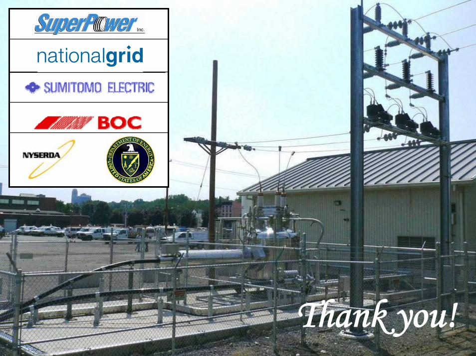
Thank you!