status report atmea1tm - aris - home status report – atmea1tm overview full name atmea1tm acronym...
TRANSCRIPT

1
Status Report – ATMEA1TM Overview
Full name ATMEA1TM
Acronym ATMEA1TM
Reactor type Pressurized Water Reactor (PWR)
Coolant Light Water
Moderator Light Water
Neutron Spectrum Thermal
Thermal capacity 3,150 MWth
Electrical capacity 1,100 MWe
Design status Detailed Design Completed
Designers AREVA NP (AREVA) and Mitsubishi Heavy Industries, Ltd (MHI)
Last update 21-12-2015
Description
1. Introduction
1.1. Generalities
ATMEATM is the joint venture created in July 2007 between AREVA NP (AREVA) and Mitsubishi Heavy Industries, Ltd (MHI). The purpose of the Joint Venture is to design, market and sell worldwide, a 1,100 MWe class evolutionary PWR that encompasses innovative and proven nuclear technologies from AREVA and MHI, including top-level safety systems, high-thermal efficiency, and a flexible 12- to 24-month operational cycle, leading to less waste and minimized impact to the environment. The primary system design, 3-loop NSSS configuration, and main components are similar to those of currently operating PWRs, thus forming a proven foundation for the design. The reactor plant has been designed for an initial 60-year operating life. ATMEA1TM has a basic set of common design features adaptable to regulatory and commercial requirements of any country in which it will be proposed. ATMEA1TM has a basic set of safety features, such as three redundant trains of emergency core cooling systems, shielded containment and shielded buildings against airplane crashes and a core-melt retention system for the mitigation of severe accidents. It is designed to meet major current sets of regulatory and commercial requirements.
1.2 Proven Technology: ATMEA1TM designed from currently operating PWRs
ATMEA1TM has been developed based on years of operating PWR experience using existing and proven components/equipment and incorporating the latest safety requirements consistent with a generation III+ plant. ATMEA1TM is considered an evolutionary design, as opposed to a revolutionary design. This strategy minimizes risks of first of a kind and allows ATMEA and its operators to utilize the experience and feedback from ~130 PWRs operating worldwide.

2
The ATMEA1TM reactor integrates evolutionary features into its design to improve safety and economy when compared to currently operating PWRs designed decades ago. Redundancy and diversification have been systematically implemented, and systems have been simplified using advanced equipment.
The systems, components, structures, design and analysis techniques, maintainability and operability features and construction techniques have several years of operation in existing nuclear power plants. Several examples of important components are as follows:
CRDM (control rod drive mechanism) and related equipment like the control rod guide assembly—the same are used in German KONVOI reactors with good operating records.
Control rods with Ag-In-Cd and B4C as absorber material—materials and designs used widely in existing French PWRs.
SG (steam generator) with axial economizer—the design is the same as implemented in the European Pressurized Reactor (EPR) and both are similar to French operating N4 plants which have good operating records and performance.
RCP (reactor coolant pump)—the reference design is used in the operating French N4 plants with minor adaptation.
Fuel (17x17, 14ft length, with M5 materials)—the fuel design is widely used in France especially in the N4 plants and in other countries
Reactor vessel and its internal structures including hydraulics—the reactor vessel design is the same as used in operating PWRs’ with appropriate size adaptation. The upper internals design is close to KONVOI design and the lower internals design is close to N4 design with minor adaptation of their sizes to the ATMEA1TM core size. The internals design is a scaled down version of the EPR internals. In addition, the hydraulic tests specific to ATMEA1TM design (full scale tests or part scale tests) are performed in order to obtain and confirm necessary hydraulic performances and characteristics for licensing, like inlet flow distribution for each fuel assembly, flow induced vibration, etc.
Cell coolers provided as a diversified second ultimate heat sink—this evolutionary feature provides an additional level of defence-in-depth for severe accident and/or extreme external hazards and has already been implemented in some of the German KONVOI reactors (e.g., GKN II).
Only a few components were newly developed and are not currently installed in operating PWRs; for example, the advanced accumulator with vortex dumper is considered to be newly developed component. However, in this case, the design is identical to the one developed by MHI for implementation in its Advanced PWR and has already been extensively tested and validated. Due to similar dimensions, materials, capacity and operating conditions, the tests are fully applicable to ATMEA1TM reactor.
Regarding systems, the major improvement from operating PWRs is an increase of redundancy and diversity (e.g., 3-train safety system instead of 2-train system and diversified division-X train). Each redundant and diversified train has a similar system configuration as existing operating reactors. Each train is directly connected to each primary loop without cross-connections to improve independency of the safety trains while maintaining the proven in the field design.
To adapt to more stringent requirements from Authorities, some systems were newly developed and do not exist in generation II PWRs (e.g., severe accident heat removal system and an extra borating system). However, these systems were developed, fully tested, and validated through extensive tests for the EPR and/or APWR reactors and have already been licensed by several safety authorities. In addition, all components (pumps, valves, tanks, etc.) used in these new systems are fully proven, tested and validated for their purposes and conditions.

3
Civil structures, support structures of equipment, and other structures are also consistent with existing PWR designs. The reactor building configuration and related layout strategy has been referenced to the Japanese experience to ensure the best seismic design and construction techniques. Regarding the protection against an air plane crash, including a large commercial airplane and/or military airplane, the reactor makes use of a typical and common bunker-type protection of all buildings housing safety equipment. The design addresses not only the impact to buildings and structures but also the induced vibrations and fires, and was satisfactorily assessed by both the French ASN and Canadian CNSC.
As for the design and analysis techniques, the latest methodology and computer codes already fully tested and validated through experienced and/or an on-going licensing process of operating PWRs, EPRs, and APWRs are applied.
Maintainability and operability are strongly related with the layout design, system configurations, and equipment design. The design fully benefits from the use of proven equipment and also from the latest and advanced requirements and guidelines for operation and maintenance through the maintenance activities carried out by AREVA and MHI on operating reactors worldwide.
1.3 Design features ATMEA1TM has a three-loop reactor coolant system (RCS) configuration. The RCS is equipped with:
A Reactor Pressure Vessel (RPV) that contains the Fuel Assemblies,
A Pressurizer (PZR) including control systems to maintain system pressure,
One Reactor Coolant Pump (RCP) per loop,
One Steam Generator (SG) per loop,
Associated piping and related control and protection systems.
The Reactor Building (RB) containment structure is of a pre-stressed concrete type with a steel liner inside. An annular space, surrounding the lower part of the RB, collects possible leakages from all penetrations. The RB is surrounded by the Safeguard Building (SB) and the Fuel Building (FB)
Redundant 100% capacity safety systems are strictly separated into three divisions. This divisional segregation is provided for electrical and mechanical safety systems. One separated backup train for Essential Service Water System (ESWS), Component Cooling Water System (CCWS) and Emergency Power Supply system (EPS) constitutes the fourth train provided for on-power maintenance of the systems of any of the other train. This fourth train is also a diverse mean for beyond Design Basis Events (DBE).
Water storage for safety injection is provided by the In-containment Refueling Water Storage Pit (IRWSP) located at the bottom of the RB. Also, inside the containment and below the RPV is a dedicated spreading area called “Core Catcher” for molten core material following a postulated worst-case severe accident.
The fuel pool is located outside the RB in a dedicated Fuel Building to simplify access for fuel handling during plant operation and handling of fuel storage casks. Fuel pool cooling is assured by two redundant cooling trains and by a diversified cooling train.
Protection against a large aircraft crash and explosions is assured using both a reinforced concrete shell and segregating safety trains.

4
2.0 Description of the Nuclear Systems 2.1 Main characteristics of the primary circuit
The primary circuit of ATMEA1TM is constituted by the main components and systems as described in § 1.3.
2.2 Reactor core and fuel design
2.2.1 Core design
The core consists of 157 Fuel Assemblies (FAs) as used in the conventional 3-loop cores designed by AREVA and/or MHI. The radial heavy neutron reflector is designed to;
improve neutron utilization, thus reducing the fuel consumption,
minimize neutron irradiation embrittlement by reducing the RPV irradiation, and
avoid stress corrosion cracking of baffle bolts and to reduce the inspection work by removing all bolts from high neutron fluence area.
The Nuclear Steam Supply System (NSSS) nominal thermal power is 3,150 MWth.
Fuel cycle lengths can be set to be from 12 to 24 months. Fuel management variations in ATMEA1TM can range from a full uranium core loading to up to 1/3 MOX fuel loading. With some minor design modifications, full MOX loading can be accommodated.
2.2.2 Fuel Assemblies
Each FA consists of fuel rods arranged in a 17x17 square array, together with 24 control rod guide thimbles.
The fuel rods have slightly enriched uranium dioxide pellets or MOX pellets. Some of the fuel rods may contain uranium dioxide pellets blended with gadolinia to control excess reactivity.
2.2.3 Reactor Cluster Control Assemblies (RCCAs) and Reactivity Control
The RCCAs of ATMEA1TM control the relatively fast reactivity changes mainly due to reactor thermal power changes and coolant temperature variations. At any reactor operating state, the RCCAs have the ability to rapidly shut down the reactor. The control rods have neutron absorbers encased in a stainless steel tube.
Soluble absorber is used to control the relatively slow reactivity changes mainly due to fuel depletion. In order to reduce boron concentration and to improve the primary water chemistry control, 10B enriched boric acid is used as a soluble absorber in the coolant.
2.3 Fuel handling systems
The fueling and refueling system handles fresh and spent fuel.
New fuel brought into the NPP is stored in fuel storage racks in the fuel handling building. After reactor shutdown, spent fuel is transferred to the spent fuel pit.

5
2.4 Primary circuit component description 2.4.1. Reactor Pressure Vessel
The RPV is subject to low neutron fluence thanks to a heavy neutron reflector (see 2.4.2), which enabled to design it for 60 years of operation. The RPV consists of three inlet nozzles and three outlet nozzles, which are located between the RPV flange and the top of the core, so as to allow a volume of coolant within the RPV to be maintained in the event of leakage in the reactor coolant loop. The RPV closure head dome and its flange are integral and made from a one-piece forging. The RPV closure head is equipped with nozzles to which the pressure housings for the CRDM are connected. The top closure head is also equipped with in-core instrumentation nozzles. The main parts of the RPV are made of low alloy steel with stainless steel cladding on all internal surfaces exposed to the reactor coolant. All other parts exposed to the coolant are made of either stainless steel or nickel base alloys.
2.4.2. Reactor internals
The RPV internals consist of upper internals and lower internals. Upper and lower internals are suspended from the RPV flange. A hold-down annular spring, compressed between the upper and lower internal flanges, ensures the internals’ vertical stability and prevents their lifting when subjected to hydraulic forces.
The heavy neutron reflector, placed inside the core barrel, is the designed to ensure low neutron fluence to the RPV and to minimize both inspection work and the risk of Stress Corrosion Cracking (SCC). The reflector is fabricated using austenitic stainless steel forged slabs, without bolts or welds thereby eliminating welds and/or bolts in high neutron fluence areas. These slabs are positioned one above the other, and axially restrained by keys and tie rods. The reflector rests on the lower support plate and extends almost all the way up the core cavity.
2.4.3. Steam generators
The SGs are vertical shell, natural circulation, u-tube heat exchangers with integral moisture separating equipment. They are fitted with an axial economizer to provide increased steam pressure. The axial economizer directs all the feedwater (FW) to the cold leg side of the tube bundle and the re-circulated water to the hot leg thanks to the double wrapper in the cold leg of the downcomer. Figure 1 illustrates the principle of the axial economizer.
This steam generator design enhances the heat exchange efficiency between the primary side and the secondary side and increases the outlet steam pressure compared to a boiler type SG with the same tube surface.
The tube material is alloy 690 TT which is widely used in SGs throughout the world, and is highly resistant to corrosion.
2.4.4. Pressurizer
The PZR is designed to accommodate positive and negative volume surges caused by load transients. The surge line, which is attached to the bottom of the PZR, connects to the hot leg of a reactor coolant loop.
6
PZR safety valves provide overpressure protection for the reactor coolant system. The spray valves limit reactor coolant system pressure rises following less severe transients to prevent undesirable opening of the PZR safety valves.
2.4.5. Reactor coolant pumps
The RCPs are vertical, single-stage, shaft seal units, driven by air-cooled, three-phase induction motors. The complete unit is a vertical assembly consisting of (from top to bottom) a motor, a seal assembly, and a hydraulic unit.
The shaft seal system is made up of a series of three seals and a standstill seal.
2.4.6. Main coolant lines
The reactor coolant pipework consists of all the pipes connecting the RPV, the SGs, the RCPs, and the PZR, together with the various branches of the main piping up to the appropriate isolating valve. It also includes instrumentation connections to the reactor coolant system that enable flow, temperature, pressure, chemical composition and radiation to be monitored.
The reactor coolant pipes and fittings are made of austenitic stainless steel. All smaller diameters piping that is part of the reactor coolant system, such as the PZR surge line, spray line, and connecting lines to other systems, are also made of austenitic stainless steel.
For the primary system, the leak Before Break concept (LBB) is only applied to the design of the main coolant lines themselves.
2.5. Reactor auxiliary systems
2.5.1. Chemical and volume control system (CVCS)
The CVCS is the interface between the high pressure RCS and the low pressure coolant treatment and supply systems. The CVCS is an operational system and has the following functions:
Control the RCS water inventory via PZR level control;
Provide make-up to the RCS in the event of small leakages; and
Adjust the boron concentration in the reactor coolant during start-up and shutdown and normal operation.
The system operates continuously and the main components of the CVCS are the high pressure charging pumps, the volume control tank (VCT), the regenerative heat exchanger, two high pressure coolers in parallel, two high pressure reducing stations, also in parallel, and a low pressure reducing station.
The two HP charging pumps take suction from the volume control tank. The volume control tank acts as a surge tank to permit smooth control of variations in charging and letdown flow rates. The HP charging pumps can also take suction from the IRWSP in the event of a low level in the VCT, in the event of a failure of the reactor boron and water make-up system, or if a boron dilution is detected.
2.5.2. Component cooling water system
The CCWS transfers heat from safety-related systems and operational cooling loads to the
heat sink, via the Essential Service Water System (ESWS), under all operating conditions.

7
The CCWS supplies cooling water to the safety and operational systems such as:
Containment Spray System (CSS) / Residual Heat Removal System (RHRS) heat exchangers and pump motors;
Spent Fuel Pit (SFP) heat exchangers;
RCP thermal barriers; and
HP coolers.
The CCWS consist of three trains (1, 2 and 3) plus one additional train (X) for On-Power
Maintenance (OPM) and also for diversity. The heat exchangers of Trains 1, 2 and 3, cooled
by the ESWS from Ultimate Heat Sink (UHS) 1 and the heat exchanger of Train X, cooled by
the ESWS from either UHS1 or UHS2, are of a different type. UHS 1 and UHS 2 are also of a
different type.
2.5.3. Essential service water system
The ESWS consists of three separate safety-related trains that provide cooling of the CCWS
heat exchangers with water from the UHS during all normal plant operating conditions,
transients, and accidents. The ESWS also includes a diverse train, Train X, for OPM.
ESWS transports heat to the UHS after removing heat from the following consumers under
all operating conditions including normal operation, residual heat removal and accidents:
CCWS heat exchangers,
EPS generators,
Others.
Trains 1, 2 and 3 of the ESWS take the essential service water from UHS 1, supply each
component being cooled, and discharge the essential service water back to UHS 1. Train X
of the ESWS takes the essential service water from UHS 2 to supply each component being
cooled, and discharges the essential service water back to UHS 2.
Each of Trains 1, 2 and 3 consists of one pump, two pump discharge strainers, one plate
type heat exchanger with inlet strainer, and the associated piping, valves and instrumentation.
Train X consists of one pump, two pump discharge strainers, and one shell & tube type heat
exchanger including cleaning unit, the associated piping, valves and instrumentation.
2.6. Operating modes
ATMEA1TM control modes and control channels allow for high flexibility in normal operation.
For frequency control, variations of 15% in power (85%-100%) throughout cycle life time are allowed.
For load-follow requirements: daily fluctuations in the energy demand characterized by a plateau at a minimum power level of 25% are permitted. ATMEA1TM is capable of even greater flexibility with instantaneous return to full power without notice (when selected) at a rate of 5% per minute. Load-follow operation can be superimposed with frequency control operation.
ATMEA1TM is also capable of fast power reductions shifting to house load operation when necessary.
8
2.7. Alternative fuel options
The ATMEA1TM core design allows for various fuel management schemes to be accommodated including full uranium cores to cores made up of 1/3 MOX cores. With some minor design changes full MOX cores can be accommodated.
3. Description of safety concept 3.1. Safety concept, design philosophy and licensing approach
3.1.1. Design philosophy
ATMEA1TM design philosophy is based on the following objectives relative to the current Generation III+ PWRs:
- Increased redundancy and segregation, - Reduced core damage frequency (CDF), - Reduced large release frequency (LRF), - Mitigation of severe accidents, - Protection of critical systems from external events (e.g. airplane crash), - Improved human-system interface, - Extended response times for operator actions.
3.1.2 Licensing status
ATMEA1TM is based on technologies developed by AREVA and MHI, which are licensed or under licensing.
ATMEA1TM’s conceptual design has been reviewed by IAEA and found compliant with the main requirements. The French Safety Authority, ASN, is reviewing ATMEA1TM’s safety options according to the French safety legislation and French technical requirements.
Under the auspices of the IAEA, an international team of senior experts reviewed the ATMEA1TM design and evaluated it against applicable IAEA Safety Standards. The report, issued in 2008, concluded that the conceptual ATMEA1TM design addresses IAEA’s Fundamental Safety Principles as well as key design and safety assessment requirements.
In mid-2010, a review of ATMEA1TM’s detailed design and safety features was began by the French Nuclear Safety Authority (ASN) in order to obtain ASN’s position about their compliance with:
the safety objectives as set out in France for the new generation of PWRs, as expressed in Section A.1.1 of the “Technical Guidelines for the design and construction of the new generation of pressurized water nuclear reactors”, and
the statutory and para-regulatory texts applicable to basic nuclear installations in France.
The ASN issued its final position on January 2012, which considered that “safety objectives adopted by the ATMEA Company for the ATMEA1 reactor are satisfactory” and that “safety options and design choices adopted for the main equipment of the ATMEA1 reactor are globally satisfactory.”
Diversifications implemented in the design (4th train, the 2nd ultimate heat sink, alternative power source, water sources, etc.) were also highly considered including in their role to address extreme external hazards.

9
In mid-2011, ATMEA started a pre-licensing review with the Canadian Nuclear Safety Commission (CNSC). CNSC pre-licensing review of a Vendor Reactor Design is a pre-requisite for selection by Canadian utilities showing that there is no outstanding issue for a subsequent licensing.
CNSC reviewed the compliance of ATMEA1 reactor design against CNSC regulatory document RD-337 “Design of New Nuclear Power Plants” and other applicable regulatory documents. The CNSC issued its final position in June 2013, which concluded that, “ATMEA understood the CNSC regulatory requirements and expectations for the design of new NPPs in Canada” and that “ATMEA1 design intent is compliant with the CNSC regulatory requirements and meets the expectations for new NPPs in Canada.”
CNSC also evaluated that ATMEA1 strategy on extreme external hazards and severe accidents are fully in line with Canadian expectations for a Generation III reactor.
3.2. Provision for simplicity and robustness of the design
Simplifications have been performed in all areas of design, construction, operation and maintenance with a view to achieving cost-effective design and to improved safety.
The advanced accumulator provides a good example of this approach. The advanced accumulator is the passive system which provides for reactor vessel refill at a high injection flow rate and for core re-flooding at a lower flow rate. As a result, low-head injection pumps are no longer necessary.
3.3. Safety systems
The use of active and passive systems has been optimized for reliability and economic purposes.
ATMEA1TM integrates all top-level safety systems with three independent active safety trains. These trains are totally separated from operational systems and are protected against external hazards.
One of the examples of the passive safety systems is the advanced accumulator as described in 3.2.
3.4. Defense-in-depth description
The safety design of ATMEA1TM is based primarily on deterministic analyses complemented by probabilistic analyses. The deterministic approach is based on the “defense-in-depth” concept which comprises five levels:
1. A combination of conservative design, quality assurance, and surveillance activities to prevent departures from normal operation;
2. Detection of deviations from normal operation and protection devices and control systems to cope with them (this level of protection is provided to ensure the integrity of the fuel cladding and of the reactor coolant pressure boundary in order to prevent accidents);
3. Engineered safety features and protective systems that are provided to mitigate accidents and consequently to prevent their evolution into severe accidents;
4. Measures to preserve the integrity of the containment and enable control of severe accidents;
5. Off-site emergency response is not per se part of the safety design although safety objectives set forth for ATMEA1 strongly limit the need for it.
For all safety analysis, the long term safe state is retained as the safe shutdown state.

10
List of design basis events is based primarily on the USNRC regulation completed by events from the designers’ experience.
Low probability events with multiple failures and coincident occurrences up to the total loss of safety-grade systems are considered in addition to the deterministic design basis (i.e. beyond design basis). Representative scenarios are defined for preventing both core melt and large releases. A probabilistic approach is used to define these events and both deterministic and probabilistic approaches are used to assess the specific measures available for their management.
Level 3 of defense-in-depth has been reinforced by addressing large commercial airplane crash and extreme external hazards.
Even though the probability of severe accidents has been greatly reduced by improving defense-in-depth’s levels 1 to 3, innovative features practically eliminate energetic scenarios that could lead to containment failure. Design provisions for a further reduction of the residual risk, core melt mitigation, and the prevention of large releases are implemented.
External events such as large commercial or military aircrafts hazards, explosion pressure wave, seismic events, missiles, tornado and fire, have been considered in the design of the shielded safeguard buildings, containment and fuel building.
3.5 Safety goals (Core Damage Frequency, large early release frequency and operator grace period) 3.5.1. Probabilistic targets and safety assessment The aim of a probabilistic safety analysis is to determine all significant contributors to the radiation risk from a facility or activity and to evaluate the extent to which the overall design is well balanced and meets probabilistic safety objectives. In the area of reactor safety, the probabilistic safety analysis has been carried out using a comprehensive, structured approach to identify failure scenarios, constituting a conceptual and mathematical tool for deriving numerical estimates of risk. The probabilistic approach used realistic assumptions and provided a framework for explicitly addressing many of the uncertainties and insights into system performance, reliability, interactions and weaknesses in the design, defense in depth and risk that may not be possible to be derived from a deterministic approach.
3.5.2. Probabilistic safety objectives The proposed figures for probabilistic safety objectives follow the international trend (e.g. the INSAG12 recommendations). Safety objectives shall not be interpreted as safety limits, but they are specified in order to ensure sufficient safety provisions in the ATMEA1TM design. Probabilistic assessment figures shall be considered as indicators as it was recognized by Safety Authorities. The Nuclear Island safety objectives are such that:
- the integral Core Damage Frequency (CDF), considering all plant states and all types of events (internal events, internal hazards and external hazards except sabotage) is
< 10-5/r.y., and - the integral Frequency of “Large Releases” (LRF) is < 10-6/r.y.

11
3.5.3. Operator action response time and Autonomy In order to limit the consequence of accidents, design provisions ensure that no operator action will be required before a given period. This minimizes the risk of operator error during diagnostics or in operator actions, in accordance with general safety objectives. In addition, achieving and maintaining safe shutdown state requires a heat sink and uninterruptible power sources. Design provisions are implemented to ensure the adequate autonomy of these sources by delaying the need to use mobile equipment as much as possible.
In view of improving the prevention of human errors and making the facility less vulnerable to these errors, reaction times are systematically considered in the safety demonstration. Operator action cannot be credited during this period. Any action required during this period is automated. Operator actions are not needed for at least 30 minutes from the main control room and 1 hour from within the plant. Beyond this period, all operator action, including the use of mobile equipment, may be credited, within the limits of the periods of autonomy mentioned below.
The emergency feedwater tanks for the steam generators are adequate to maintain hot shutdown for a period more than or equal to 24 hours. Safeguarded electrical supply and SBO supply each have an autonomy of more than or equal to 7 days while safety-class batteries have an autonomy of more than or equal to 2 hours. Dedicated severe accident batteries have an autonomy of more than or equal to 12 hours. The autonomy of the main heat sink UHS1 is 30 days, in line with the requirements of U.S. NRC Regulatory Guide 1.27. Standard ATMEA1 location is assumed to be near sea coast, in which case the UHS1 would be the sea which can be considered as an infinite cooling source. In addition, beyond the requirements of RG 1.27 on UHS1 autonomy, the autonomy of the diversified ultimate heat sink UHS 2 must be adequate to restore the main ultimate heat sink if the latter fails.
3.6. Safety systems to cope with Design Basis Event (DBE) 3.6.1. Safety system configuration
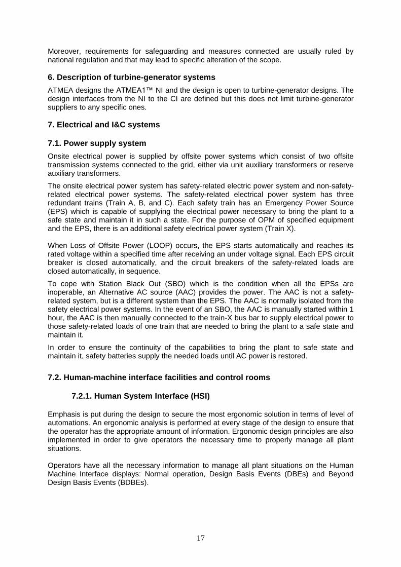
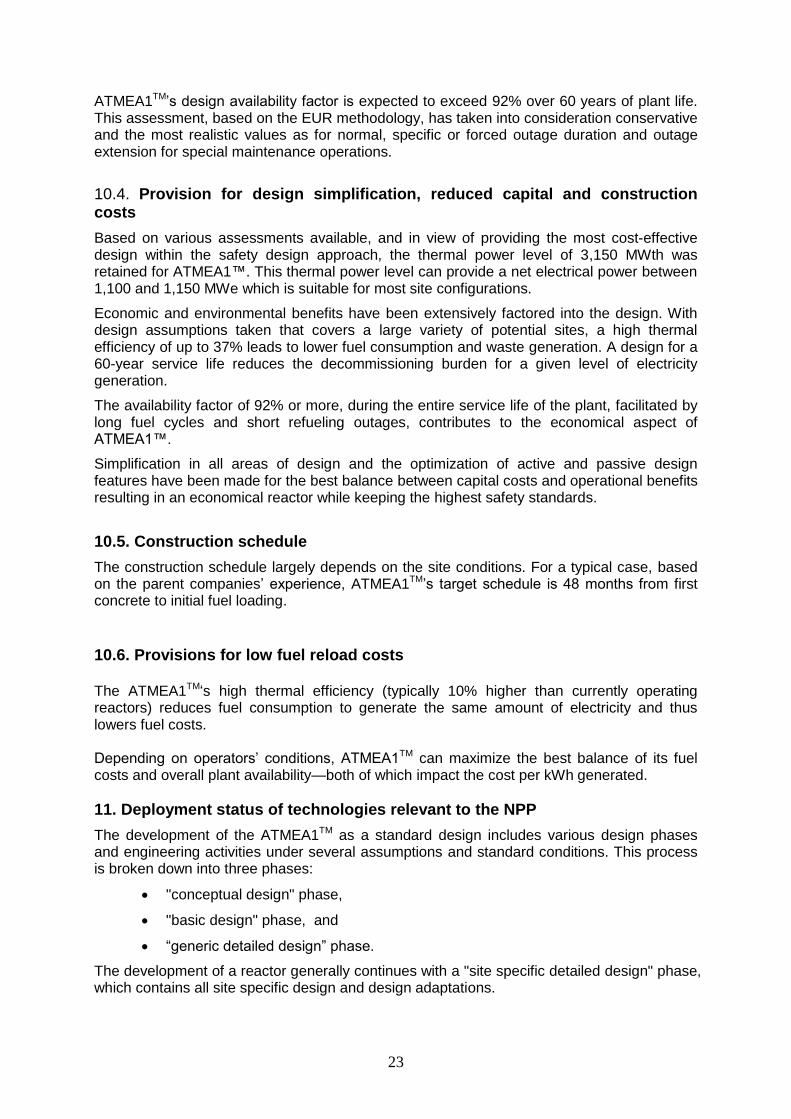
The main features of the ATMEA1TM safety systems are three independent trains which are respectively fitted to the three reactor loops. The general arrangement of the safety systems are shown in Figure 2. The additional fourth train is installed for cooling chain systems, which provides both an On-Power Maintenance (OPM) capability and diversity. The general arrangement of the cooling chain systems are shown in Figure 3.
Advanced accumulators achieve functions of high flow injection during the blowdown phase just after a Loss of Coolant Accident (LOCA) and low flow injection during the subsequent core re-flooding phase.
3.6.2. Safety injection system (SIS)
SIS injects and re-circulates medium head emergency coolant to maintain the reactor core’s coolant inventory following a LOCA, or following a Main Steam Line Break (MSLB). SIS consists of three independent identical trains. Each train has a Medium Head Safety Injection (MHSI) pump and an advanced accumulator pressurized by nitrogen. Each train has its own suction connection to the IRWSP In-containment refueling water storage pit (IRWSP) via a series of screens, thus protecting the MHSI pumps against debris being entrained with the IRWSP fluid.
12
3.6.3. In-containment refueling water storage pit (IRWSP)
The IRWSP is located inside the containment for the following reasons :
to avoid switching over from injection mode to recirculation mode after the tank(s) are empty in the event of a LOCA or a steam line break, and
to provide water for corium cooling in the event of a core melt.
The IRWSP is situated at the bottom of the containment and around the reactor pit. The area between the IRWSP and containment wall is filled with concrete in order to avoid non-recoverable water losses during accident conditions. Other areas without concrete filling, relevant for water losses, are taken into account in the IRWSP volume balance.
3.6.4. Emergency feedwater system (EFWS)
The EFWS feeds water to the SGs to maintain their water level and to remove decay heat following the loss of normal FW supplies due to Anticipated Operational Occurrence (AOO) and DBE conditions. This ensures the removal of the heat from the RCS, which is transferred to the secondary side via the SGs and via the SG Main Steam Relief Valves (MSRV) to the atmosphere.
The EFWS has sufficient capacity and independence to perform its required safety functions following DBEs, assuming a single failure in one EFWS train.
The EFWS has three separate and independent trains, each consisting of a water storage pool, pump, control valves, isolation valves, piping and instrumentation and powered by a separate electrical train. In the event of a common mode failure of all EPSs, one of the motor-driven EFW pumps can be powered by a diversified Alternative AC Power Source (AAC).
One EFWS train is located in each division of the Safeguard Buildings (SAB), providing separation and/or physical protection to cope with external and internal hazards. The storage pools are made of concrete with internal liner and are a structural part of SB.
3.6.5. Containment spray system (CSS)/Residual heat removal system (RHRS)
The CSS/RHRS performs normal shutdown cooling, as well as containment spray injection to maintain RB conditions within design limits in the event of a LOCA, Main Steam Line Break (MSLB) or Main Feedwater Line Break (MFLB).
The CSS/RHRS has safety functions such as the reduction of pressure and temperature inside the containment, down to acceptable levels in the event of a LOCA, MSLB or MFLB as well as the normal operational functions such as reaching and maintaining safe shutdown state and refueling conditions.
The CSS/RHRS has sufficient capacity, and independence to perform its required safety functions following design basis transients or accidents, assuming a single failure in one train.
The CSS/RHRS consists of three independent trains, with separate suction connections to the IRWSP; the sumps have a series of screens, ensuring protection of the CSS/RHRS spray pumps against debris being entrained in the IRWSP fluid.
All three CSS/RHRS trains are powered from separate emergency buses, each backed up by an EPS. Each CSS/RHRS train is located in the associated division in SAB, thereby providing separation and/or physical protection from external and internal hazards.

13
3.6.6. Extra borating system (EBS)
The EBS injects borated water into the RCS in the event of DBEs in order to maintain the core subcritical for safe shutdown.
The EBS is composed of two identical trains. Each EBS train is composed of its own boron tank, a high pressure 100% capacity pump, a test line and injection lines to the RCS.
The EBS is also used to cope with ATWS which is defined as an Anticipated Operational Concurrence (AOO).
3.7. Safety system to cope with severe accidents
A severe accident results in fuel rod failure, degradation of the structural integrity of the reactor core, and release of radioactive fission products into the reactor coolant system. Such an event can only occur as a result of a sustained loss of adequate core cooling, which leads to elevated core temperatures due to the sustained production of decay heat. Coupled with multiple failures of a plant’s safety-grade emergency cooling systems, the resulting consequence of melting the reactor core (and internals) may lead to the breaching of the reactor vessel. The transfer of molten core material in the containment may potentially compromise the ability of the containment to perform its radionuclide retention function.
The ATMEA1TM safety concept responds to advanced regulatory requirements, which require that the plant is designed to cope with a severe accident in such a way that the consequences are limited to the immediate vicinity and render stringent countermeasures unnecessary, such as evacuation or the relocation of the neighboring population as well as long term restrictions in the consumption of food.
This goal is achieved by a severe accident mitigation design which closely follows the design of the EPR by the following design measures;
Depressurization of the RCS to reliably prevent high pressure vessel failure and induced steam generator piping rupture,
Avoidance of ex-vessel steam explosion and re-criticality,
Hydrogen control to prevent early containment failure and large fission product release,
Melt retention to prevent basemat penetration,
Containment heat removal to prevent late containment failure and increased fission product release, and
Monitoring of overall plant behavior (leak tightness), activity distribution within the containment and releases to the environment.
3.8. Provisions for safety under seismic conditions For the standard design, the SSE is taken equal to 0.3g (horizontal acceleration free field level) and the US NRC ground response spectra, as defined in RG 1.60, is used. This value is an envelope of European countries, most of the USA and some of Asian countries. In the USA, this value is described in the top tier of the URD. If site conditions exceed this value, the seismic relief devices will be adopted so as not to affect the layout or support structures. To minimize the impact of adopting the seismic relief devices, layout considerations, such as a flat common base mat, were already taken into account in the standard design.

14
3.9. Probabilistic risk assessment (PSA)
The aim of a PSA is to determine all the significant contributors to the risk from the plant and to evaluate the extent to which the overall design is well balanced and meets the probabilistic safety objectives. The combined Level 1 and level 2 PSA were carried out with a comprehensive, structured approach to identify failure scenarios, constituting a conceptual and mathematical tool for deriving numerical estimates of risk. The probabilistic approach uses realistic assumptions whenever possible and provides a framework for addressing many uncertainties explicitly. Probabilistic approaches were used to provide insights into system performance, reliability, interactions and weaknesses in the design, defense-in-depth and risk that cannot be derived from a purely deterministic approach.
3.10. Emergency planning measures
ATMEA1TM adopts radiological consequences criteria consistent with those used for reactors currently under construction in Europe.
These criteria ensure limited emergency response planning and limit the surrounding areas that might possibly be affected during an accident. This applies in both the short and the long term after an accident, long-term referring to tens of years.
For infrequent and limiting faults, the following overall criteria apply:
- No short term countermeasures (shelters, evacuation, distribution of iodine tablets), - No need for long-term relocation, and - Food restrictions are limited to the immediate vicinity of the affected reactor plant site. Corresponding dose limits for taking action as a result of a reactor accident are country-specific; however, the following thresholds apply in France in order to protect the surrounding populations:
An effective dose of 10 mSv: protect the population,
An effective dose of 50 mSv: evacuate the population,
An equivalent thyroid dose of 50 mSv: administer iodine tablets.
Distances are 500m (typical limit of site) for the short term phase and 2 km from the release location for the long term. Although severe accidents are beyond design basis events, ATMEA1™ criteria are also extremely stringent.
The severe accident overall approach is consistent with objectives established for radiological consequences that can be interpreted as “maintain its role as a reliable, leak-tight barrier throughout the accident and in the long term for the relevant severe accident sequences and phenomena”.
- No need for short-term countermeasures over the first 24 hours. Criterion: an effective dose of 50 mSv; Short-term countermeasures (shelters, evacuation) are required only in the immediate vicinity of the site. Distances are defined above. Criterion: Sheltering (effective dose) 10 mSv ; Evacuation (effective dose) 50mSv ; Iodine distribution (Dose equivalent to the thyroid) 100 mSv; Long and short term measures (Relocation: 10 mSV/month for long exposure (irradiation dose rate from the ground) or 1 Sv (Effective dose))
- No long-term relocation is necessary, except for the population residing in the immediate vicinity of the site. Criterion: vicinity of the site: 1000 mSv and 10mSv/month at the vicinity of the site;

15
- Restricted consumption applies only to the first harvest following the event. Criterion: European Union limits.
4. Proliferation resistance
The ATMEA1TM renders the diversion or undeclared production of nuclear materials or misuse of technology, by host state, very difficult due to inherent technical impediments. On the one hand the declared inventory is not appealing and diversion of either fresh or spent fuel elements is made difficult by design; on the other hand undeclared production of weapon grade materials has a very significant cost and is easily detectable.
4.1. Intrinsic barriers The intrinsic barriers that reduce the risk of diversion or misuse pathways are summarized here below.
4.1.1. Fresh fuel
The ATMEA1TM is designed for operation with fissile material that has a poor attractiveness from the proliferation point of view. Fresh fuel assemblies are made of;
low enriched uranium fuel (LEU) with enrichments limited to less than 5% 235U (i.e., far below "weapon-grade),
or of a uranium-plutonium mixture known as Mixed Oxide fuel (MOX) with reactor grade plutonium coming from the reprocessing of LWR fuel.
Diversion of LEU fuel assemblies for use as feed in enrichment devices and/or diversion of fresh MOX assemblies for processing to separate plutonium are made extremely difficult. A fuel assembly weights more than half a metric ton and requires specific equipment to be lifted. Furthermore the fuel assemblies are handled and stored in the fuel building which is protected by a heavy shielding and has limited and controlled access.
4.1.2. Fuel under irradiation
When the reactor is operating the reactor pressure vessel is closed and the fuel is inaccessible. Refueling operation with an open vessel and fuel transfers occur under transparent water shielding permitting direct visual observation for safeguards purposes.
4.1.3 Spent fuel handling and storage in fuel pool
LEU fuel which has gone through a normal operating life (e.g. 3 fuel cycles) will reach a high burn-up, so it is of limited interest for proliferation purpose: the 235U content is below 1% and the poor isotopic quality of the plutonium leads to high neutron emission rate, high heat emission and high level of radiation.
In the spent MOX fuel assembly, the remaining plutonium content has an even worst isotopic quality, and thus a further reduced attractiveness. In both cases, the spent fuel is highly radioactive and would require a heavily shielded cask to be moved, therefore theft is unrealistic.
4.1.4. Misuse of the reactor for producing weapon grade plutonium
The design of the reactor vessel internal structure does not leave room to allow irradiation of specific uranium target. Moreover, producing plutonium for proliferation purpose will need irradiated fuel with low burnup in order for its quality to be of practical interest.
16
The normal operating fuel cycle for the reactor being between 1 and 2 years before shutdown for refueling, short cycle durations would obviously be detected by safeguard inspectors.
4.2. Safeguard ability
The design of the reactor plant facilitates the implementation of safeguard inspections control and accounting measures that are the extrinsic barriers enforcing institutional agreements and policies.
Refueling operation and associated fuel movements are conducted at a low frequency and take place in only two building that may easily be placed under surveillance. The integrity of these building boundaries is ensured by the structure designed against external hazards. The few access points allow monitoring and surveillance of all passages.
5. Safety and Security (physical protection)
Security provisions are integrated in the design to deal with malevolent actions by protecting sensitive structures, systems and components and by allowing the implementation of security procedures during operation and maintenance activities. The objectives are the integrity of nuclear materials and NPP safety features, to avoid the threat of radiation for the public or any theft of nuclear fuel. Stipulations on physical protection are mostly classified information, and only some general principles are given here below. The plant arrangement and the design of the buildings allow implementing different levels of security areas accessible only after passing access control points. The plant area is surrounded with the site fence, including the gatehouse, the vehicle barrier…These security features are usually within the plant owner responsibility. Resistance of walls and closure (e.g. doors, grids) is required for the protected area as well as the surveillance of all passage. Within the protected area, the vital area contains all the systems and equipment important to plant safety or security and the storage of the nuclear material. Boundaries between areas with different security level are structural barriers designed against unauthorized access. Specific features allow monitoring, surveillance and recording of all passages through the boundary between the different areas. Physical protection of the vital areas against destructive acts from outside is typically based on:
provision against external hazards, such as the physical separation of redundant systems and the implementation of the air plane crash protection structure,
design features implemented for coping with station blackout; they provide grace periods in case of destructive acts from outside, this time allowing to restore water inventories and/or to recover damaged plant equipment.
security provision made to prevent and to detect incorrect inputs in the I&C systems and equipment.
Physical protection against unauthorized manipulations of an authorized person within the vital area takes benefit from the segregation of the redundant trains of the mechanical, electrical and I&C safety systems. To ensure the plant security of any project, features addressing the same general principles as those considered in the reference design are implemented. For every project, the detailed definition and design of the security provisions have to be achieved independently of the other projects in order to ensure the confidentiality of the information.
17
Moreover, requirements for safeguarding and measures connected are usually ruled by national regulation and that may lead to specific alteration of the scope.
6. Description of turbine-generator systems
ATMEA designs the ATMEA1™ NI and the design is open to turbine-generator designs. The design interfaces from the NI to the CI are defined but this does not limit turbine-generator suppliers to any specific ones.
7. Electrical and I&C systems 7.1. Power supply system
Onsite electrical power is supplied by offsite power systems which consist of two offsite transmission systems connected to the grid, either via unit auxiliary transformers or reserve auxiliary transformers.
The onsite electrical power system has safety-related electric power system and non-safety-related electrical power systems. The safety-related electrical power system has three redundant trains (Train A, B, and C). Each safety train has an Emergency Power Source (EPS) which is capable of supplying the electrical power necessary to bring the plant to a safe state and maintain it in such a state. For the purpose of OPM of specified equipment and the EPS, there is an additional safety electrical power system (Train X). When Loss of Offsite Power (LOOP) occurs, the EPS starts automatically and reaches its rated voltage within a specified time after receiving an under voltage signal. Each EPS circuit breaker is closed automatically, and the circuit breakers of the safety-related loads are closed automatically, in sequence.
To cope with Station Black Out (SBO) which is the condition when all the EPSs are inoperable, an Alternative AC source (AAC) provides the power. The AAC is not a safety-related system, but is a different system than the EPS. The AAC is normally isolated from the safety electrical power systems. In the event of an SBO, the AAC is manually started within 1 hour, the AAC is then manually connected to the train-X bus bar to supply electrical power to those safety-related loads of one train that are needed to bring the plant to a safe state and maintain it.
In order to ensure the continuity of the capabilities to bring the plant to safe state and maintain it, safety batteries supply the needed loads until AC power is restored.
7.2. Human-machine interface facilities and control rooms
7.2.1. Human System Interface (HSI)
Emphasis is put during the design to secure the most ergonomic solution in terms of level of automations. An ergonomic analysis is performed at every stage of the design to ensure that the operator has the appropriate amount of information. Ergonomic design principles are also implemented in order to give operators the necessary time to properly manage all plant situations. Operators have all the necessary information to manage all plant situations on the Human Machine Interface displays: Normal operation, Design Basis Events (DBEs) and Beyond Design Basis Events (BDBEs).

18
7.2.2. Main Control Room (MCR)
For all plant conditions (except if the MCR becomes inaccessible) the plant is supervised and controlled from the MCR. The MCR is equipped with identical operator workstations consisting of Process Information and Control System (PICS) driven screens and soft controls. These operator workstations are used as follows:
two operator workstations are staffed during normal plant operations;
a third operator workstation is used by the shift supervisor; and
a fourth operator workstation is staffed during plant states requiring increased operating and monitoring tasks (e.g., refueling period, post accident conditions).
7.2.3. Remote Shutdown Station (RSS)
If the MCR becomes inaccessible the operators supervise and control the plant from the RSS. The RSS is equipped with:
Manually-actuated switches for disconnecting all the MCR equipment that may send spurious signals to Level 1 systems and switching the RSS workstations to control mode. Technical and administrative precautions prevent spurious or unauthorized actuation of this function;
Operator workstations consisting of PICS-driven screens and soft controls which are of the same type and provide the same functionality as those in the MCR. The operators can bring the plant to a safe shutdown state and monitor plant conditions from these operator workstations;
Communication equipment for maintaining communications with other plant personnel;
Fire fighting controls.
7.3. Reactor Protection System (RPS) and other safety systems The Instrumentation and Controls (I&C) system provides is critical to the proper functioning of the RPS and provides the following functions:
Controls and monitors plant system functions during normal operations;
Controls plant functions that initiate corrective measures in the event of deviation from LCO;
Controls limitation functions that initiate corrective measures;
Controls protection functions that mitigate the consequences of a DBE up to the controlled state;
Controls and monitor post-accident functions that mitigate the consequences of a DBE, and to bring and maintain the plant from the controlled state to the safe shutdown state; and
Controls functions that mitigate the consequences of BDBEs, including severe accidents.
The general I&C architecture is designed in accordance with the concept of diversity and defense-in-depth.
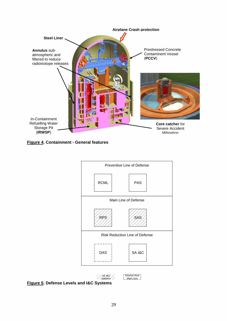
Instrumentation and control systems are combined into three defense levels:

19
the level corresponding to normal operation and to incident-prevention functions (including the RCML and the PAS),
main level of defense (including RPS and SAS), and
the risk reduction level (including the DAS and the SA I&C dedicated to manage severe accidents).
The application of this concept requires independence between the different levels.
Figure 5 shows the positioning of each of the instrumentation and control systems in each of the defense levels.
The I&C system used as human-machine interface are designed to allow the operator to monitor and control the unit in all circumstances, and are assigned to all defense levels. The functions used in normal operating conditions are guaranteed by I&C systems assigned to preventive line of defense. The Main Line of Defense can be used to achieve and maintain safe shutdown state after a DBE 2 – 4 condition event.
The Risk Reduction Line can be used to provide additional resources in order to:
limit the consequences of credible common cause failures for main level I&C systems, when they are combined with a DBE 2 – 4 condition (DEC-A sequence),
limit the consequences of a severe accident with core meltdown (DEC-B sequence).
The safety I&C system of the Main Line of Defense are located in dedicated cabinets in the nuclear island. The RPS system has four logic channels. Depending on the system design and requirement the protective each function is implemented using 3 or 4 channels logics. Each of Trains A, B, C and X is installed in a dedicated independent room associated to different fire zones and with independent safety HVACs. Each of them has its own safety-related power source. Additionally, each cabinet has redundant power supplies.
8. Spent fuel and waste management 8.1. General
With steam generator axial economizer technology and optimized operating parameters of
the primary loops, the thermal efficiency of A TMEA1TM
is 37% (the actual value depending
however on site conditions), which is around 10% more than the current operating plants, leading to less fuel consumption and less waste generation for the same amount of energy produced.
8.2. Spent fuel
The standard design of ATMEA1TM
provides for an on-site storage of the spent fuel at the
spent fuel pool for 10 years of full power operation. Beyond this period, plant operators decide whether to store the spent fuel assemblies on site or to ship them to an interim storage facility or a reprocessing plant where they will be recycled. Materials, such as plutonium and uranium, will be re-used.
The plutonium originating from reprocessed spent fuel is recycled in the form of mixed uranium and plutonium oxides fuel (MOX).
8.3. Radioactive Wastes
General safety objectives have been defined relative to the protection of the public and the environment. These objectives lead to the minimization of liquid and gaseous effluent

20
discharges and to the minimization of the volume of solid waste produced, as compared with the nuclear facilities currently in use.
The process to minimize effluents and waste, leads to:
the identification of the sources of production of these effluents and waste,
the implementation of design provisions aiming to limit the production and discharge of effluents (collection, processing, storage and decay equipment before discharge) and the production of waste.
the implementation of resources to monitor the discharge of effluents (periodic and continuous measuring equipment in the environment).
The waste building stores radioactive waste in a controlled area which is readily accessible for reception and dispatch and has sufficient capacity to store waste for an operationally appropriate period.
9. Plant Layout 9.1. Buildings and Structures
The ATMEA1™ Nuclear Island (NI) consists of:
The Reactor Building (RB), the Safeguard Auxiliary Building (SAB) and the Fuel Building (FB), which are located on a common basemat;
The Nuclear Auxiliary Building (NAB), two EPS Buildings, the Radioactive Waste Processing Building, and the Access Control Building, which are located on individual basemats.
The Essential Service Water related buildings and galleries.
The Turbine Building (TB) is independent from the Nuclear Island (NI).
9.1.1. External and internal hazards
For a new NPP design, as a countermeasure against extreme external events, ATMEA1 strategy is to use installed equipment and resources to maintain or restore core cooling, containment cooling, and spent fuel cooling for a prolonged period of time.
The objective is, for extreme external hazard conditions, including potential consequential long-term LUHS and loss of EPS power, as well as their relevant combinations:
to prevent core melt in reactor vessel and to limit radiological consequences should a core melt occur in reactor vessel (defense-in-depth approach),
to exclude fuel melt in fuel building,
The extreme external hazards means are organized in two different levels of Defense in Depth:
A Preventive Level of Defense, whose objective is to avoid Core Melt in the reactor and spent fuel uncovering and criticality in the Spent Fuel pool in case of extreme external hazards. This level of defense is ensured by preventive Extreme Hazards Protected (EHP) Equipment;
A Mitigation Level of Defense, whose objective is to limit radiological consequences in the event of Core Melt in the reactor, and to avoid spent fuel uncovering and criticality in the Spent Fuel pool in case of extreme external hazards combined with the failure of Preventive line of Defense for SFP. This level of defense is ensured by mitigation EHP Equipment.

21
Most safety functions of NPPs depend on alternating current (AC) power, hence high reliability of AC power supply is essential. This high reliability is achieved through an adequate combination of redundancy and diversity. Ensuring adequate protection of the AC power supply against site-specific extreme external hazards is a lesson from the Fukushima Daiichi accident. Regarding emergency power supply, diverse, electrically adequately isolated AC power sources (AAC) is implemented as a part of defense-in-Depth concept of the plant.
The Defense-in-Depth approach needs to be applied also to the ultimate heat sink. The design of new nuclear power plants needs to provide diverse means to provide reactor and spent fuel cooling. The use of a secondary ultimate cooling water system (UHS2) is an acceptable diverse means to provide reactor and spend fuel cooling for decay heat removal in case of unavailability of the primary ultimate heat sink.
For both lines of defense, ATMEA1 baseline strategy is to credit the AAC, the UHS2 and EHP equipment and to protect them against site-specific extreme external hazards. Short, mid and long terms definition and additional means are adjusted to the site specificities, to country’s requirements or to address investment protection purposes.
Internal hazards are events originating on the plant site with the potential to cause adverse conditions or even damages inside or on safety classified buildings (e.g., internal fires, flooding, missiles or explosions). Such effects can potentially lead to common cause failures within systems needed to reach or maintain the plant in a safe state.
Within buildings containing safety systems, two main cases are considered depending on the layout type of building where the internal hazard occurs. These are:
• buildings which are split into divisions, e.g. safeguard buildings, diesel buildings,
• buildings or parts of them which are not split into divisions, e.g. containment.
The protection against internal hazards is taken into account in the design of the plant through layout requirements (mainly spatial and/or structural separation of individual redundancies of safety related systems from each other and from non-safety related system as far as reasonable achievable) and/or design against loads. These requirements are adapted to the two buildings of different type as described above.
External hazards are considered as load cases. Protection relies upon both the deterministic dimensioning of the structures and equipment with respect to reference load cases and, for some hazards affecting only part of the plant, on segregation of systems and components.
The robustness of the design against hazards is a combination of the seismic design with a large common basemat with specific layout in the inner structures of the buildings, and of the large commercial airplane crash protections.
9.1.2. Radiation protection
Stringent radiation protection requirements limit personnel exposure during operation and while performing in-service inspection and maintenance to very low levels. The design target for the maximum collective dose exposure is less than 0.5 man-Sv per year.
The SAB is separated into radiologically controlled (“hot”) and non-controlled (“cold”) areas. Those systems that are radiologically “cold” under normal conditions, such as the CCWS and EFWS, are separated (including the dedicated access locations) from the systems that are radiologically “hot,” such as the RHRS. This arrangement minimizes the necessity for personnel to enter contaminated areas.
Primary layout design features providing radiation protection include the following:
Equipment is located in separate compartments (tanks/heat exchangers, pumps and valves) according to access requirements and anticipated radiation levels;

22
Access to radioactive components is provided via shielded service routes and transition from areas with lower radiation levels to areas with higher radiation levels.
9.2. Containment
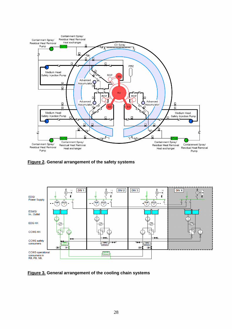
The RB contains the major NSSS components and piping along with some associated auxiliary systems. The RB consists of the Containment Building (also called the Pre-stressed Concrete Containment Vessel (PCCV) and its internal structural surrounded, in the lower part, by the annulus space and an outer wall of reinforced concrete (see Figure 4).
The RB has a steel liner covering the inner surface of the PCCV.
The RB is located at the center of the NI. It is surrounded by the SAB and FB which are on a same basemat. It is designed to withstand internal accidents as well as external hazards including the following: earthquake, APC, EPW, missiles, tornado, and fire.
In the event of a LOCA or severe accident, the RB retains all radioactive material and withstands the maximum pressure and temperature resulting from the release of stored energy.
The design pressure and temperature that the containment building must withstand are defined by the following events:
Double-ended rupture of a reactor coolant pipe (Large Break LOCA (LBLOCA));
Main steam line break; and
Severe accidents.
10. Plant performance 10.1 Plant operation
The reference configuration (nominal power) for ATMEA1TM is:
Net electrical power: 1,100-1,150 MWe with a 35-37% efficiency;
NSSS output : 3,150 MW thermal;
Fuel cycle lengths from 12 to 24 months.
10.2. Reliability
ATMEA1TM is composed of either operated, licensed, or certified systems or components, integrating the most modern proven technologies developed by AREVA and MHI and implemented respectively into AREVA’s EPRTM and MHI’s APWR. The fact that the ATMEA1™ design is derived from both reactors contributes to its safety and reliability.
10.3. Availability targets
Several design features contribute to achieve short outage and easy maintenance:
On-power maintenance capability
Accessible reactor building
Layout provisions for maintenance
High speed refueling machine
High capacity coolant purification system
23
ATMEA1TM’s design availability factor is expected to exceed 92% over 60 years of plant life. This assessment, based on the EUR methodology, has taken into consideration conservative and the most realistic values as for normal, specific or forced outage duration and outage extension for special maintenance operations.
10.4. Provision for design simplification, reduced capital and construction costs
Based on various assessments available, and in view of providing the most cost-effective design within the safety design approach, the thermal power level of 3,150 MWth was retained for ATMEA1™. This thermal power level can provide a net electrical power between 1,100 and 1,150 MWe which is suitable for most site configurations.
Economic and environmental benefits have been extensively factored into the design. With design assumptions taken that covers a large variety of potential sites, a high thermal efficiency of up to 37% leads to lower fuel consumption and waste generation. A design for a 60-year service life reduces the decommissioning burden for a given level of electricity generation.
The availability factor of 92% or more, during the entire service life of the plant, facilitated by long fuel cycles and short refueling outages, contributes to the economical aspect of ATMEA1™.
Simplification in all areas of design and the optimization of active and passive design features have been made for the best balance between capital costs and operational benefits resulting in an economical reactor while keeping the highest safety standards.
10.5. Construction schedule
The construction schedule largely depends on the site conditions. For a typical case, based on the parent companies’ experience, ATMEA1TM’s target schedule is 48 months from first concrete to initial fuel loading.
10.6. Provisions for low fuel reload costs The ATMEA1TM‘s high thermal efficiency (typically 10% higher than currently operating reactors) reduces fuel consumption to generate the same amount of electricity and thus lowers fuel costs. Depending on operators’ conditions, ATMEA1TM can maximize the best balance of its fuel costs and overall plant availability—both of which impact the cost per kWh generated.
11. Deployment status of technologies relevant to the NPP
The development of the ATMEA1TM as a standard design includes various design phases and engineering activities under several assumptions and standard conditions. This process is broken down into three phases:
"conceptual design" phase,
"basic design" phase, and
“generic detailed design” phase.
The development of a reactor generally continues with a "site specific detailed design" phase, which contains all site specific design and design adaptations.

24
In April 2015, the Generic Detailed Design for ATMEA1TM was completed with the issuance of the revision of the Preliminary Safety Analysis Report (PSAR), the component data sheet and the documentation for procurement.

25
APPENDIX: Summarized ATMEA1TM
Technical Data (ATMEA1TM
)
General plant data
Reactor thermal output 3,150 MWth
Power plant output, gross MWe
Power plant output, net 1,100-1,150 MWe
Power plant efficiency, net 35-37 %
Mode of operation Baseload and
load follow +
frequency control
Plant design life 60 Years
Plant availability target > 92 %
Seismic design, SSE 0.3g
Primary Coolant material Light water
Moderator material Light water
Safety goals
Core damage frequency < 10-5
/RY
Large early release frequency < 10-6
/RY
Occupational radiation exposure < 0.5 Person-Sv/RY
Nuclear steam supply system
Steam pressure 7.2 (BE at SG
outlet)
MPa(a)
Reactor coolant system
Primary coolant flow rate 24800 (BE) m3/h/loop
Reactor operating pressure 15.5 MPa(a)
Reactor vessel inlet temperature 291 (BE) ℃
Reactor vessel outlet temperature 326 (BE) ℃
Reactor core
Fuel material UO2 or MOX
Cladding tube material Zirconium based
alloy
Rod array of a fuel assembly 17x17
Number of fuel assemblies 157
Enrichment of reload fuel at equilibrium core < 5.0 Wt%
Fuel cycle length 12 to 24 months
Burnable absorber (strategy/material) Gd2O3 kg
Control rod absorber material AIC/B4C
Soluble neutron absorber Enriched H3BO3
Reactor pressure vessel
Inner diameter of cylindrical shell 4250 mm
Base material Low alloy steel
Steam generator
Type U tubes with axial
economizer

26
Number 3
Total tube outside surface area 8,000 m2
Tube outside diameter 19 mm
Tube material Alloy 690
Reactor coolant pump
Type Shaft seals
Number 3
Flow at rated conditions 24,800 m3/h
Pressurizer
Total volume 65 m3
Primary containment
Type Pre-stressed
concrete with steel
liner
Overall form (spherical/cylindrical) Cylindrical
Residual heat removal systems
Active/passive systems Active
Safety injection systems
Active/passive systems Active pumps and
passive advanced
accumulators

27
Figure 1. Steam Generator and Axial Economizer
28
Figure 2. General arrangement of the safety systems
Figure 3. General arrangement of the cooling chain systems
29
Figure 4. Containment - General features
Preventive Line of Defense
SA I&C
SASRPS
DAS
PASRCML
Diverse from
Main Line1E I&C
platform
Main Line of Defense
Risk Reduction Line of Defense
Figure 5. Defense Levels and I&C Systems
Annulus sub-atmospheric and filtered to reduce radioisotope releases
In-Containment Refuelling Water
Storage Pit
(IRWSP)
Core catcher for Severe Accident
Mitigation
Prestressed Concrete Contaminent Vessel (PCCV)
Airplane Crash protection
Steel Liner