status of the diamond light source r. bartolini diamond light source ltd and john adams institute,...
TRANSCRIPT
Status of the Diamond Light SourceStatus of the Diamond Light Source
R. Bartolini
Diamond Light Source Ltdand
John Adams Institute, University of Oxford
ILCWCERN, Geneva, 20th October 2010

OutlineOutline
• Introduction to Diamond
• Beam optics studies (linear and nonlinear)
• Beam stability
• Low alpha optics and THz emission
• Customised optics
ILCWCERN, Geneva, 20th October 2010
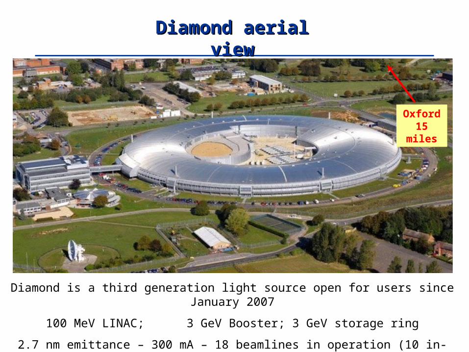
Diamond aerial viewDiamond aerial view
Diamond is a third generation light source open for users since January 2007
100 MeV LINAC; 3 GeV Booster; 3 GeV storage ring
2.7 nm emittance – 300 mA – 18 beamlines in operation (10 in-vacuum small gap IDs)
Oxford 15 miles

Diamond storage ring main parametersDiamond storage ring main parametersnon-zero dispersion latticenon-zero dispersion lattice
Energy 3 GeV
Circumference 561.6 m
No. cells 24
Symmetry 6
Straight sections 6 x 8m, 18 x 5m
Insertion devices 4 x 8m, 18 x 5m
Beam current 300 mA (500 mA)
Emittance (h, v) 2.7, 0.03 nm rad
Lifetime > 10 h
Min. ID gap 7 mm (5 mm)
Beam size (h, v) 123, 6.4 m
Beam divergence (h, v) 24, 4.2 rad
(at centre of 5 m ID)
Beam size (h, v) 178, 12.6 m
Beam divergence (h, v) 16, 2.2 rad
(at centre of 8 m ID)
48 Dipoles; 240 Quadrupoles; 168 Sextupoles (+ H and V orbit correctors + 96 Skew Quadrupoles)
3 SC RF cavities; 168 BPMs
Quads + Sexts have independent power supplies
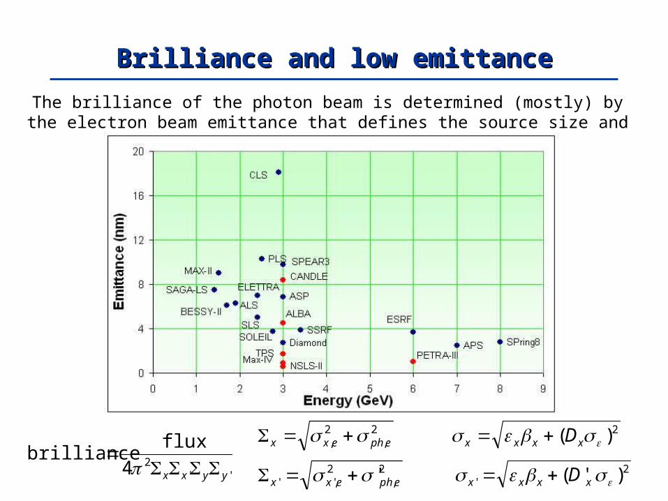
The brilliance of the photon beam is determined (mostly) by the electron beam emittance that defines the source size and divergence
Brilliance and low emittanceBrilliance and low emittance
''24 yyxx
fluxbrilliance
2,
2, ephexx
2,
2,'' ' ephexx
2)( xxxx D
2' )'( xxxx D

Linear optics modelling with LOCOLinear optics modelling with LOCOLLinear inear OOptics from ptics from CClosed losed OOrbit response matrix – J. Safranek et al.rbit response matrix – J. Safranek et al.
Modified version of LOCO with constraints on gradient variations (see ICFA Newsl, Dec’07)
- beating reduced to 0.4% rms
Quadrupole variation reduced to 2%Results compatible with mag. meas. and calibrations
0 100 200 300 400 500 600-1
-0.5
0
0.5
1
S (m)
Hor
. Bet
a Bea
t (%
)
0 100 200 300 400 500 600-2
-1
0
1
2
S (m)
Ver
. Bet
a Bea
t (%
)
Hor. - beating
Ver. - beating
LOCO allowed remarkable progress with the correct implementation of the linear optics
0 50 100 150 200-7
-6
-5
-4
-3
-2
-1
0
1
2
3
4
Quad number
Str
ength
variation f
rom
model (%
)
LOCO comparison
17th April 2008
7th May 2008
Quadrupole gradient variation

Linear coupling correction with LOCOLinear coupling correction with LOCO
j,i
2BPMsBPMsq
modelij
measuredijBPMsqBPMs
2 ,...)k,G,S,Q(RR,...)k,S,G,Q(
Skew quadrupoles can be simultaneously zero the off diagonal blocks of the measured response matrix and the vertical disperison

Residual vertical dispersion after correctionResidual vertical dispersion after correction
Without skew quadrupoles off r.m.s. Dy = 14 mm
After LOCO correction r.m.s. Dy = 700 μm
(2.2 mm if BPM coupling is not corrected)
ILCWCERN, Geneva, 20th October 2010

Measured emittancesMeasured emittances
Coupling without skew quadrupoles off K = 0.9%
(at the pinhole location; numerical simulation gave an average emittance coupling 1.5% ± 1.0 %)
Emittance [2.78 - 2.74] (2.75) nm
Energy spread [1.1e-3 - 1.0-e3] (1.0e-3)
After coupling correction with LOCO (2*3 iterations)
1st correction K = 0.15%
2nd correction K = 0.08%
V beam size at source point 6 μm
Emittance coupling 0.08% → V emittance 2.2 pm
Variation of less than 20% over different measurements

Lowest vertical emittanceLowest vertical emittance
Model emittance
Measured emittance
-beating (rms) Coupling*
(y/ x)
Vertical emittance
ALS 6.7 nm 6.7 nm 0.5 % 0.1% 4-7 pm
APS 2.5 nm 2.5 nm 1 % 0.8% 20 pm
ASP 10 nm 10 nm 1 % 0.01% 1-2 pm
CLS 18 nm 17-19 nm 4.2% 0.2% 36 pm
Diamond 2.74 nm 2.7-2.8 nm 0.4 % 0.08% 2.2 pm
ESRF 4 nm 4 nm 1% 0.25% 10 pm
SLS 5.6 nm 5.4-7 nm 4.5% H; 1.3% V 0.05% 2.8 pm
SOLEIL 3.73 nm 3.70-3.75 nm 0.3 % 0.1% 4 pm
SPEAR3 9.8 nm 9.8 nm < 1% 0.05% 5 pm
SPring8 3.4 nm 3.2-3.6 nm 1.9% H; 1.5% V 0.2% 6.4 pm
SSRF 3.9 nm 3.8-4.0 nm <1% 0.13% 5 pm
5 pm
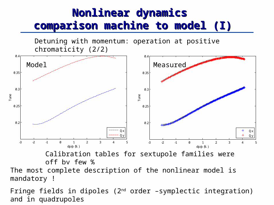
Nonlinear dynamics Nonlinear dynamics comparison machine to model (I)comparison machine to model (I)
-3 -2 -1 0 1 2 3 4 5
0.2
0.25
0.3
0.35
0.4
dp/p (%)
Tun
e
Qx
Qy
-3 -2 -1 0 1 2 3 4 5
0.2
0.25
0.3
0.35
0.4
dp/p (%)
Tun
e
Qx
Qy
Model Measured
Detuning with momentum: operation at positive chromaticity (2/2)
Calibration tables for sextupole families were off by few %
The most complete description of the nonlinear model is mandatory !
Fringe fields in dipoles (2nd order –symplectic integration) and in quadrupoles
Higher order multipoles in dipoles and quadrupoles (from measurements)

FLS2010, SLAC, 02 March 20100 0.002 0.004 0.006 0.008 0.01 0.012 0.014
0
0.5
1
1.5
2
2.5
3
3.5x 10
-3
x [m]
y [m
]
nturn = 1024
-10
-9
-8
-7
-6
-5
-4
-3
0 2 4 6 8 10 12 140
0.5
1
1.5
2
2.5
3
3.5
Horizontal Amplitude (mm)
Ver
tical
Am
plitu
de (
mm
)
Dynamic Aperture at Injection Point
Stable>0.1% loss
2nd order
3rd order
4th order
5th order6th order
10
20
30
40
50
60
0.2 0.21 0.22 0.23 0.24 0.25 0.260.33
0.335
0.34
0.345
0.35
0.355
0.36
0.365
0.37
0.375
0.38
x
y
Frequency Map
-10
-9
-8
-7
-6
-5
-4
-3
0.2 0.21 0.22 0.23 0.24 0.25 0.260.33
0.335
0.34
0.345
0.35
0.355
0.36
0.365
0.37
0.375
0.38
Qx
Qy
Measured frequency map
10
20
30
40
50
60
Nonlinear dynamics Nonlinear dynamics comparison machine to model (II)comparison machine to model (II)
DA measured FM measured
FM modelDA model
1)
Substantial progress after understanding the frequency response of
the Libera BPMs
2)
Octupole component in the dipoles reduced by
a factor 5
3)
H DA limited by the orbit ILK, not by nonlinearities
(tracking data do not proceed further to larger amplitudes)

Orbit stability: disturbances and requirementsOrbit stability: disturbances and requirements
Beam stability should be better than
10% of the beam size
10% of the beam divergence
up to 100 Hz
but IR beamlines will have tighter requirements
Ground settling, thermal drifts Ground vibrations, cooling systems
Insertion Device Errors Power Supply Ripple
Hertz0.1 1 10 100 1000
for 3rd generation light sources this implies sub-m stability
• identification of sources of orbit movement
• passive damping measures
• orbit feedback systems

mmx 3.121231.0 radradx 4.2241.0'
mmy 6.04.61.0
xx 1.0 '1.0' xx yy 1.0 '1.0' yy
Beam stability should be better than 10% of the beam size
For Diamond nominal optics (at short straight sections)
radrady 4.041.0'
IR beamlines might have tighter requirements
Orbit stability requirements for DiamondOrbit stability requirements for Diamond
ILCWCERN, Geneva, 20th October 2010

Seismometer mounted on top of a quadrupoleSeismometer mounted on top of a quadrupole
ILCWCERN, Geneva, 20th October 2010

Ground vibrations to beam vibrations: DiamondGround vibrations to beam vibrations: Diamond
Amplification factor girders to beam: H 31 (theory 35); V 12 (theory 8);
1-100 Hz
Horizontal Vertical
Long StraightStandard Straight
Long StraightStandard Straight
Position (μm)
Target 17.8 12.3 1.26 0.64
Measured 3.95 (2.2%) 2.53 (2.1%) 0.70 (5.5%) 0.37 (5.8%)
Angle (μrad)
Target 1.65 2.42 0.22 0.42
measured 0.38 (2.3%) 0.53 (2.2%) 0.14 (6.3%) 0.26 (6.2%)

Significant reduction of the rms beam motion up to 100 Hz;
Higher frequencies performance limited mainly by the correctors power
supply bandwidth
Global fast orbit feedback: DiamondGlobal fast orbit feedback: Diamond
1-100 Hz
Standard Straight H
Standard Straight V
Position (μm)
Target 12.3 0.64
No FOFB 2.53 (2.1%) 0.37 (5.8%)
FOFB On 0.86 (0.7%) 0.15 (2.3%)
Angle (μrad)
Target 2.42 0.42
No FOFB 0.53 (2.2%) 0.26 (6.2%)
FOFB On 0.16 (0.7%) 0.09 (2.1%)

Passive improvement of orbit stabilityPassive improvement of orbit stability
Girder vibrationsGirder vibrations
Elimination of vibrations at 24.9 Hz after fixing water cooling pump mountings
horizontal vertical
next target: air handling units, 18 Hz

Higher average brightness• Higher average current
• Constant flux on sample
Improved stability• Constant heat load
• Beam current dependence of BPMs
Flexible operation• Lifetime less important
• Smaller ID gaps
• Lower coupling
Top-Up motivationTop-Up motivation
BPMs block stability
• without Top-Up 10 m
• with Top-Up < 1 m
Crucial for long term sub- m stability
ILCWCERN, Geneva, 20th October 2010

Top-Up mode (I)Top-Up mode (I)
Moved from the “Standard” operation: 250 mA maximum, 2 injections/day
No top-up failures, no beam trips due specifically to top-up
First operation with external users, 3 days, Oct. 28-30
ILCWCERN, Geneva, 20th October 2010
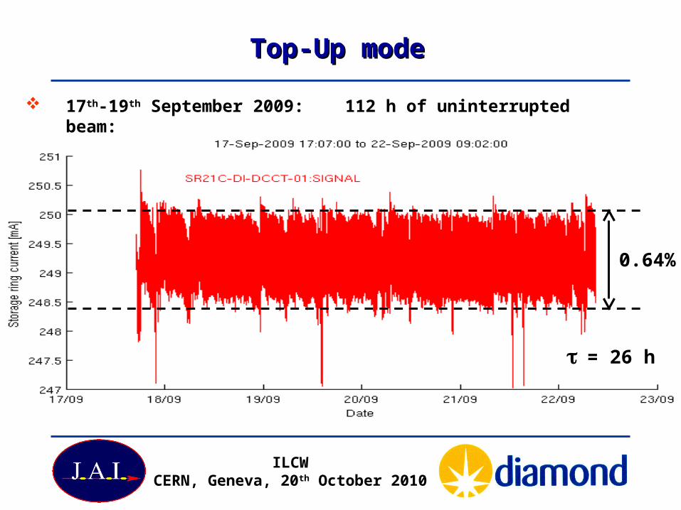
Top-Up modeTop-Up mode
17th-19th September 2009: 112 h of uninterrupted beam:
0.64%
= 26 h
ILCWCERN, Geneva, 20th October 2010

Improvement of orbit stability in Top-Up modeImprovement of orbit stability in Top-Up mode
- measured using one of the photon BPMs (fixed ID gap)
- in both cases, Fast Orbit Feedback (electron BPMs) ON
-2
0
2
an
gle
[u
rad
]
-2
0
2
an
gle
[u
rad
]
0 5 10 15 20150
200
250
time [h]be
am
cu
rre
nt
[mA
]
horizontal angle
vertical angle
x’/10
y’/10

Time resolved science requires operating modes with single bunch or hybrid fills to exploit the short radiation pulses of a single isolated bunch
Bunch length in 3Bunch length in 3rdrd generation light sources generation light sources
The rms bunch length is increases with the stored
charge per bunch
(PWD and MI)
Modern light sources can operate a wide variety of fill patterns (few bunches, camshaft)

Low – alpha optics
Higher Harmonic Cavities
RF voltage modulation
Femto–slicing
1) shorten the e- bunch 2) chirp the e-bunch + slit or optical compression
3) Laser induced local energy-density modulation
e– bunch
Crab Cavities
Synchro-betatron kicks
There are three main approaches to generate short radiation pulses in storage rings
Ultra-short radiation pulses in a storage ringUltra-short radiation pulses in a storage ring

dzVdf
c
RFsz /2
3
Short bunches at DiamondShort bunches at Diamond
(low_alpha_optics) (nominal) /100
6101 ds
D
Lx
z(low alpha optics) z(nominal)/10
We can modify the electron optics to reduce
The equilibrium bunch length at low current is
Comparison of measured pulse length for normal and low momentum compaction
2.5 ps is the resolution of the streak camera
Shorter bunch length confirmed by synchrotron tune measurements
fs = 340Hz => α1 = 3.4×10⁻⁶, σL = 1.5ps
fs = 260Hz => α1 = 1.7×10⁻⁶, σL = 0.98ps

Low alpha lattices at DiamondLow alpha lattices at Diamond
0 10 20 30 40 50 60 70 80 90
0
20
S (m)
Bet
a F
unct
ion
(m)
x
y
x
0 10 20 30 40 50 60 70 80 90
0
0.5
Dis
pers
ion
(m)
15.2 15.4 15.6 15.8 16 16.2 16.4 16.6
-0.2
-0.1
0
0.1
0.2
(m
)
s (m)15.2 15.4 15.6 15.8 16 16.2 16.4 16.6
-5
0
5
(c
m)
Measured values:
Emittance = 35.1 ± 1.5 nm.rad (34)
En. Spread = 0.13 ± 0.02 %
Coupling = 0.04 ± 0.01%

Low alpha lattices at DiamondLow alpha lattices at Diamond
0 10 20 30 40 50 60 70 80 90
0
10
20
30
S (m)
Bet
a F
unct
ion
(m)
x
y
x
0 10 20 30 40 50 60 70 80 90
0
0.2
Dis
pers
ion
(m)
15.2 15.4 15.6 15.8 16 16.2 16.4 16.6
0
S (m)
Bet
a F
unct
ion
(m)
15.2 15.4 15.6 15.8 16 16.2 16.4 16.6
0
Dis
pers
ion
(m)
Measured values:
Emittance = ~4 nm.rad (4.2)
En. Spread = ~0.1%
Coupling = ~0.6%

α1 -2-3×10⁻⁶
Bunch Length ~ 5 ps (rms)
Bunch Current ~ 80 A
Lifetime ~ 12 h
Emittance ~ 4 nm.rad
Coupling < 0.6%
multibunch operation (0.36 mA)
low-alpha operating point (since Easter 2009)
“hybrid” bunch (3.2 mA)
Low-alpha OperationLow-alpha Operation
user operation in low alpha in now provided only with the low emittance 4 nm closer to nominal emittance
normal lattice
low-alpha lattices

Coherent THz detection @ DiamondCoherent THz detection @ Diamond
Diamond operates with short electron bunches for generation of Coherent THz radiation
This operating regime is severely limited by the onset of the microbunch instabilities.
Sub-THz radiation bursts appeared periodically while the beam was circulating in the ring
A ultra-fast Schottky Barrier Diode sensitive to the radiation with 3.33-5mm wavelength range was installed in a dipole beamport;
1.9 mA 3.0 mA 5.2 mA

Coherent THz emissionCoherent THz emission
100
101
10-7
10-6
10-5
10-4
10-3
10-2
bunch current (uA)
pow
er (
arb.
)
=-1x10⁻⁵ (1.5MV)
=-6x10⁻⁶ (1.5MV)
=-1x10⁻⁵ (2.2MV)
=-6x10⁻⁶ (2.2MV)
SSRFShanghai, 20nth May 2010
Recent experiments in low-alpha have shown a strong coherent THz emission, The quadratic dependence of the THz emission with current was clearly detected

I13: “Double mini-beta” and Horizontally I13: “Double mini-beta” and Horizontally Focusing OpticsFocusing Optics
Same again in March 2011 for
I09
4 new quadrupoles
new mid-straight girder
existing girders modified
future in-vacuum undulators

mid-straight girder with two new quadrupoles
make-up vessel in place of future in-vacuum
undulator
modified main girder with additional
quadrupole

Customised optics in straight 13Customised optics in straight 13
ILCWCERN, Geneva, 20th October 2010
As regards beam dynamics, the new optics works well and has been well corrected.
At high current beam instabilities appear which can be overcome, but further work is required to ensure operation is as robust as the nominal optics.
The aim is to run for users with the new optics before the end of Run #5
Beta-function errors with respect to the model:

ConclusionsConclusions
Diamond is a state-of-the-art third generation light source
An intense campaign of Accelerator Physics studies is ongoing to better understand and improve the machine performance
Careful alignment and independent power supplies in all quadrupoles have allowed a very good control of the linear optics
Several very different optics have all been succesfully operated with residual beta beating of 1% or less., with excellent coupling control.
Two major development programmes already completed: Top Up operation and Low Alpha
Thank you for your attention