status of sic research for accident tolerant fuels of sic research for accident tolerant fuels...
TRANSCRIPT

Status of SiC Research for Accident Tolerant Fuels Shannon Bragg-Sitton Idaho National Laboratory Advanced LWR Fuels Technical Lead Advanced Fuels Campaign Advanced LWR Fuels Pathway Lead Light Water Reactor Sustainability Program August 2013

Outline
Overview of DOE SiC research Severe accident modeling: MELCOR analysis w/SiC Recent characterization test results
– Oxidation kinetics – Irradiation studies – Fuel-clad interactions – Elastic property measurement – Thermal properties – Failure model analysis – Quench testing
Technology development – ASTM standards development – SiC/SiC joining technology
2

SiC Gap Analysis and Feasibility Study
SiC Gap Analysis / Feasibility – Milestone report issued July 30, 2013
– Incorporates results of work funded
under multiple programs: • Fuel Cycle R&D Advanced Fuels
Campaign • Light Water Reactor Sustainability • Fusion Materials Research
(Office of Science)
3

Key Outcomes of SiC Gap Analysis and Feasibility Study
Preliminary computational analysis results (SiC-modified MELCOR) suggest significant improvement in the reactor coping time with SiC materials versus Zr-alloys under a selected loss of coolant accident (LOCA) scenario – Applies available monolithic SiC oxidation data – Includes sensitivity analysis on oxidation rate (10x) and thermal
conductivity (0.1x) – minimal peak T difference
Many data and technology gaps remain, particularly for SiC composite materials
Insufficient data currently available to draw a clear conclusion regarding the potential licensing and adoption of SiC components in LWR applications
Specific recommendations for additional testing and characterization discussed at the end of this presentation
4

PRELIMINARY MODELING RESULTS – SEVERE ACCIDENTS
5

Modeling and Analysis of Advanced Cladding and Components
Scoping analyses to estimate potential performance improvements for ATF concepts under normal operating conditions, off-normal conditions and severe accidents. – Normal operation (BISON) –
• Addition of SiC material properties • Capability to model multi-layered cladding
– Severe Accidents (MELCOR) • Addition of SiC properties (alternate for Zirconium alloy) • Currently modifying to allow additional material, multi-layered materials
– Scoping Probabilistic Risk Assessment • Within LWRS Risk Informed Safety Margin Characterization • Incorporation of MELCOR and BISON results to perform PRA • Development of analysis framework - in progress
– Baseline accident scenarios (identified in International Metrics meeting): • TMI-2 (INL) • Fukushima 3 (ORNL) 6

MELCOR Severe Accident Analysis for SiC Cladding and Components
A modified version of MELCOR with Zr replaced by SiC, including the nonlinear oxidation process for monolithic SiC in steam and oxygen atmospheres
This version of MELCOR was benchmarked against data from R. P. Arnold1, R. C. Robinson2, and E. J. Opila3 to ensure that the oxidation model was working properly
SiC-modified MELCOR was applied to a BWR (Peach Bottom) mitigated long-term station blackout and a PWR (Surry) unmitigated short-term station blackout accident scenarios4
7
10-1
10-2
100
5.8 6.0 6.2 6.4 6.6 6.8
SiC
Wt.
Loss
(mg/
cm2 -
hr)
10,000/T(K)
1200 C 1300 C 1400 C
LEAN-BURN
RICH-BURN
MELCOR Robinson Rich-Burn
MELCOR Robinson Lean-Burn MELCOR Hashimoto
0 10 20 30 40 50 Time (h)
-1.0
-0.5
0.0
0.5
Wei
ght C
hang
e (m
g/cm
2 )
SiC (linear loss rate) SiO2 (parabolic weight gain) Net
1Master of Science Thesis, MIT, September 2011 2American Ceramic Society, 82 [7], 1999, 1817-25 3American Ceramic Society, 80 [1], 1997, 197-205 4INL/LTD-12-27861, December, 2012

MELCOR Severe Accident Analysis for SiC
Comparison of MELCOR predicted maximum cladding temperature during a TMI-2 accident
– Water level drops below active fuel height 100 m into accident
– At 125 m oxidation heating in Zr clad system accelerates clad T rise
– Zr clad failure at ~145 m – loss of cladding and core geometry (failure criterion is a T set point)
– SiC clad reaches peak Tclad of 1830K, below Tmelt of the silica scale (1873K) – MELCOR calculations with existing SiC data show that it would not have failed
MELCOR predicted clad oxidation heating
– Two orders of magnitude less for SiC than for Zircaloy
– @150 m Zr heating exceeds core decay heat by factor of 5
– SiC produced more than 10 times less explosive gas during the accident analysis than Zircaloy
8

MELCOR Severe Accident Analysis for SiC
Comparison of MELCOR predicted maximum cladding temperature during a TMI-2 accident
– Water level drops below active fuel height 100 m into accident
– At 125 m oxidation heating in Zr clad system accelerates clad T rise
– Zr clad failure at ~145 m – loss of cladding and core geometry (failure criterion is a T set point)
– SiC clad reaches peak Tclad of 1830K, below Tmelt of the silica scale (1873K) – MELCOR calculations with existing SiC data show that it would not have failed
MELCOR predicted clad oxidation heating
– Two orders of magnitude less for SiC than for Zircaloy
– @150 m Zr heating exceeds core decay heat by factor of 5
– SiC produced more than 10 times less explosive gas during the accident analysis than Zircaloy
9

ADVANCED CHARACTERIZATION OF SILICON CARBIDE COMPOSITES
10

1 m/min flow
SiC: Minimal Reaction
10µmCVD-SiC
Coated Uncoated
FCRD Advanced ATF Clad Development initial screening – better than Zircaloy?
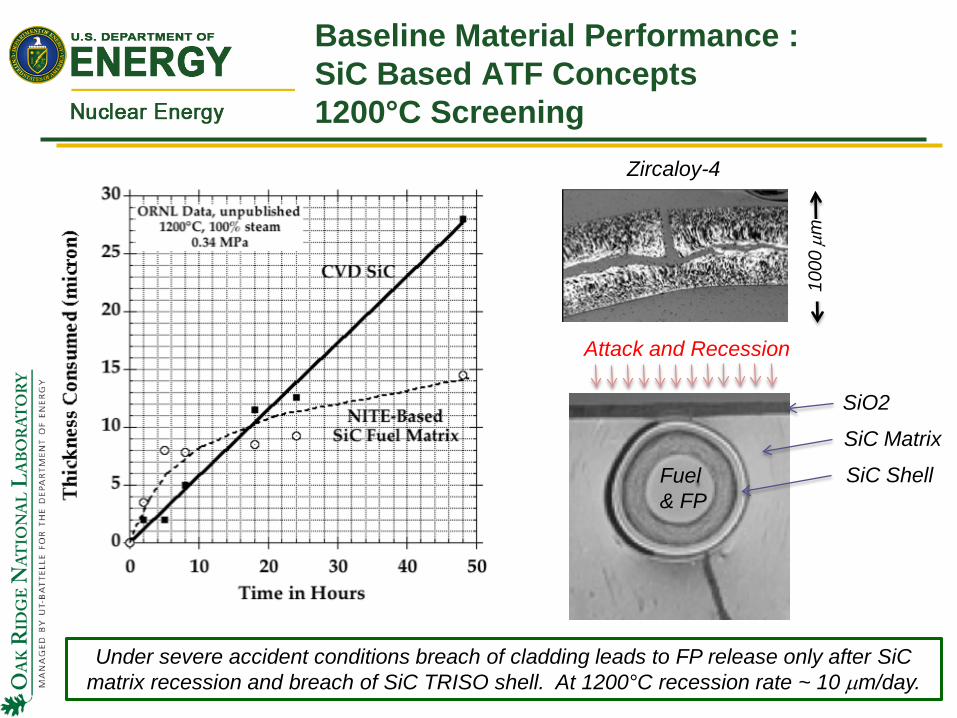
1000
µm
Zircaloy-4
SiO2
SiC Matrix
SiC Shell Fuel & FP
Attack and Recession
Under severe accident conditions breach of cladding leads to FP release only after SiC matrix recession and breach of SiC TRISO shell. At 1200°C recession rate ~ 10 µm/day.
Baseline Material Performance : SiC Based ATF Concepts 1200°C Screening

1400 1500 1600 1700
-1.4
-1.2
-1.0
-0.8
-0.6
-0.4
-0.2
0.0
0.2
Spec
imen
Mas
s Ch
ange
[mg/
cm2 ]
Temperature [°C]
2 hour test 4 hour test
100% Steam flowing at 63 cm/s
1400 1500 1600 1700
-1.4
-1.2
-1.0
-0.8
-0.6
-0.4
-0.2
0.0
0.2
145 cm/s
Spec
imen
Mas
s Ch
ange
[mg/
cm2 ]
Temperature [°C]
2 hour test 4 hour test
100% Steam flowing at 63 cm/s
Increasing Flow Rate
19 cm/s
Atmospheric Pressure Steam Tests on CVD-SiC to 1700ºC
200µm
100µm
CVD-SiC
SiO2
1700°C – 100% steam – 2 h – 63 cm/s flowCu coating
Thin SiO2
1 µm
Surface View
Cross Section

Engineering Design and Safety Analysis: Oxidation Kinetics System (OKS @ INL) (LWRS)
Out of pile / out of cell evaluation of advanced cladding materials under simulated LOCA conditions
Partial immersion/ refill quenching
INL System Design (out of pile testing only)
SiC tube samples used in this study: (a) CMC sleeve formed from woven β-SiC fibers that was used to reinforce Zr-702 tubes during deformation testing; (b) monolithic α-SiC tube.
Induction heating of a
2-ply SiC-CMC, Zr-702 hybrid
sample.

Zr-702 tube w/SiC CMC (2-ply, 150mm) 500 psig He, 915 OC, steam (LWRS)
SiC CMC sleeve shown to stabilize the Zr-702 tube along the length of the reinforcement
15
Deformation profile of a Zr-702 tube reinforced with a 150 mm long × 11.3 mm OD SiC-CMC sleeve. Ballooning and rupture of the Zr-702 tube occurred outside the reinforced area near the end of the heated zone.
Results qualitatively indicate strength enhancement through the addition of a SiC CMC sleeve to an inner Zr-alloy tube. Method of “sealing” the SiC CMC to the Zr-tube requires refinement,
and full-length SiC CMC sleeve has not yet been tested.

SiC Clad Technology Development: HFIR Irradiation, PIE Status (LWRS)
TRIPLEX SiC / UO2 capsules irradiated in HFIR – 2 pins pulled: 10 GWd/MTU and 20 GWd/MTU – Shipped to hot cell for examination; both capsules visually examined
SiC/UN capsules were also irradiated, but there currently are no plans to perform PIE on these pins
The PIE effort includes several key steps: – Sectioning of capsules to remove outer encapsulation – Removal of SiC rods – Visual inspection of SiC rods – Gamma scanning – Puncturing and gas sampling – Sectioning and opening of SiC capsules – Metallography – Radiochemistry (based on time and funding available)
PIE is expected be completed by end of August (report December 2013)
16

SiC Clad Technology Development: Diffusion Couple Study (LWRS)
Reactivity of high purity CVD SiC and “CVC” SiC (TREX proprietary) with UO2 was experimentally examined.
Substantial reactions were found after heat treatment at 1500°C for 4 hrs, whereas no reaction was confirmed at 500°C for 96 hrs.
CVC SiC (inner layer of TRIPLEX clad) was found to be significantly more reactive with UO2 at 1500°C.
Optical micrographs indicating no SiC – UO2 reaction at 500°C (top) and substantial reaction of UO2 in particular with CVC SiC at 1500°C (bottom).
EBSD Phase maps of CVD SiC – UO2 and CVC SiC – UO2 boundaries after heat treatment at 1500°C for 4 hrs. Checker flag region on left represents SiC.
Potential future work will include development of temperature-dependent reaction map and determination of reaction kinetics for high purity SiC – UO2 system.
500°C, 96 hrs
1500°C, 4 hrs
CVD SiC
CVC SiC
UO2
CVD SiC CVC
SiC
UO2
LWRS Level 3 Milestone (M3LW-13IN0502045): “Document out-of-pile testing to assess chemical interaction of fresh UO2 fuel with candidate SiC clad materials”, July 1, 2013, work conducted at ORNL.

Advanced SiC CMC Characterization: Elastic Constants (LWRS)
Measurement of elastic constants – Accurate knowledge of elastic properties is critical to designing new CMC cladding materials
with the appropriate dimensional tolerances – Elastic properties of SiC-CMC are defined in large part by the specific fiber weave and the
interaction of fibers with the matrix – Fibers introduce directionality to the CMC causing the elastic properties to become direction
dependent (elastic anisotropy) – Dynamic elastic constants can be measured using ultrasonic techniques – Testing to date has begun to measure the elastic properties of a candidate SiC-CMC material – Measurements must be performed on the specific CMC material (same fiber, weave,
matrix, etc.) for the intended in-reactor application to ensure proper component design to meet dimensional tolerances
18

Advanced SiC CMC Characterization: Thermal Properties (LWRS)
The composite matrix transports the majority of the thermal energy – SiC fibers have a lower thermal conductivity than monolithic SiC – Possibility for considerable thermal contact resistance between the fiber and matrix
further limits thermal transport Understanding degradation of thermal conductivity in the matrix and the
fiber is essential to understanding thermal transport in the composite material
Initial evaluation: SiC-CMC composite composed of Nicalon Type S fibers – Can extract thermal diffusivity and thermal contact resistance from data shown
19
Thermal wave phase scan in matrix and across fiber/matrix interface. Inset: micrograph of scanned region. Key Results / Conclusions:
Thermal contact resistance between the fiber and matrix may have a substantial contribution to a reduction in composite thermal conductivity
Understanding the change in contact resistance with thermal cycling and irradiation dose will help resolve the mechanisms that limit thermal transport in SiC-CMC materials

Purpose: Testing and evaluation of microcracking and failure behavior of SiC CMCs to develop probability of failure estimates
Alpha-SiC Testing – Weibull statistics generated for 27 samples tested under internal pressurization conditions;
associated fractography was performed to identify failure – Internal pressurization results
compared to those generated by diametral compression, axial tension, and flexure
Beta-SiC Testing – Weibull statistics generated 10 ten samples tested under internal pressurization conditions;
associated fractography was performed to identify failure – Strength was much lower than that of the α-SiC studied (26 MPa, m = 11.7); failure was found
to occur due to volume flaws Composite Testing
– Internal pressurization testing, single layer and double layer composite tubes – Single layer tubes had an average strength of 138 MPa (stdev 3.3 MPa) – Double layer tubes had an average strength of 172 MPa (stdev 52 MPa)
Test Method Characteristic Strength (MPA)
Weibull Modulus
Associated Flaw Population Sampled
Axial Tensile 320 10.0 Volume Internal Pressurization
Original Estimate Revised Estimates
132 137 108 146
5.3 5.8
93.2 10.2
Both Volume and Surface Both Volume and Surface
Surface Volume
Diametral Compression 253 31.7 Surface
C-Ring Flexure 299 4.6 Surface Perpendicular to Circumferential Direction
Sectored Flexure 192 5.5 Surface Parallel to Circumferential Direction
Failure Analysis for Wound Composite Ceramic Cladding Assembly (LWRS)

• Continuous fiber CVI SiC/SiC • Tube furnace in air – water bath quench • No evidence of chipping, gross micro-cracking or weight loss following quench • Steam oxidation in 1200-1700°C range, 4 hr showed negligible material loss
Work of Ken Yueh-EPRI, Kurt Terrani-ORNL
EPRI Channel Box Quench Test

SILICON CARBIDE TECHNOLOGY DEVELOPMENT
22

Development of ASTM Standards for Ceramic Matrix Composites in Nuclear Service
Goal – Develop plan to codify critical standards for ceramic matrix composite (CMC) based LWR
fuel cladding – Establish full-consensus standards that are essential for development and qualification of
CMC nuclear components
LWRS role: – Supports test standards development in ASTM C28 on Advanced Ceramics in collaboration
with other programs – LWRS lead role in standards for hoop tensile properties and joint shear strength, while taking
support roles in development of other standards – Interacting with ASME design code development for nuclear CMC components
Status
– Draft standards to be submitted in Fall 2013 for first subcommittee balloting – Receive comments; discuss at Jan 2014 subcommittee meeting
23

Initial Preparations for SiC CMC Interlaboratory Round Robin Testing
SiC/SiC Composite Tubes for Tensile Inter-Laboratory Round Robin Study
• Small diameter SiC/SiC composite tube test articles previously designed and fabricated were made available for the LWRS round robin study
• Tube specimens with tapered ends were fabricated with braided Hi-Nicalon and Hi-Nicalon Type S preforms and chemically vapor-infiltrated SiC matrices by Hyper-Therm High Temperature Composites (now Rolls-Royce High Temperature Composites)
24

Preparation for Round Robin Study for ASTM C1773-13 Tube Axial Tensile Test Standard is in Progress
Design of a self-aligning grip fixture is being finalized
Dummy specimens (currently being prepared) will be used before starting tests with SiC/SiC test articles
Lead test study at ORNL will establish the detailed standard test procedure to be adopted in an inter-laboratory test campaign
Work beginning under LWRS; future funding undetermined

Preliminary Plan for Round Robin Study on Tube Axial Tensile Test
Program Phase Period Task Items
Current March 2014 • Complete inter-laboratory study plan including a preliminary list of participating teams.
• Establish detailed test procedure and practices through a lead test study at ORNL.
Follow-up Phase I March 2015 • Prepare kits of test materials and instructions for distribution to participating teams.
• Organize the round robin testing process.
• Compile and analyze results. Follow-up Phase II March 2016 • Review and discuss Phase I results.
• Update C1773 with a section of Precision and Bias added.

SIC JOINING TECHNOLOGY DEVELOPMENT
Oak Ridge National Laboratory General Atomics
Rolls-Royce High Temperature Composites
27

SiC Joining and Irradiation Studies at ORNL
Miniature torsion specimens of SiC joints have been prepared for irradiation study following successful establishment of diffusion bonding technology with Ti or Mo active insert. Design and thermal analysis of
rabbit vehicle are complete for neutron irradiation of these torsion specimens in a target region of High Flux Isotope Reactor. Progress on track toward
proposed irradiation in FY-2014 (funding TBD)
28
Thermal analysis shows that temperature of the joint sections are maintained in a 290 – 320°C range.
BSE
Uniform phase Ti3SiC2
20 µm
Ti diffusion bonding showing uniform and intact bonding of two SiC substrates.
Miniature torsion specimens of Ti diffusion-bonded SiC joints
LWRS Level 3 Milestone (M3LW-13IN0504073): “Issue Report Summarizing SiC Joining & Irradiation Studies”, July 31, 2013.

SiC/SiC Joining General Atomics
Research to produce a mechanically robust and impermeable joint between an end plug and a SiC-SiC tube representative of an LWR SiC- SiC clad fuel rod for subsequent irradiation testing under conditions representative of an LWR core environment.
Identification of the most successful and promising joint – Specifics of bonding materials and procedure proprietary – Mechanical strength and impermeability benefit from increased bond length – Quantified improvement in bond strength with bond length
10 mm long scarf joint shown to be the most robust in four-point bend strength
– Note that planar testing is insufficient for characterization of more complex cylindrical geometries
29

SiC/SiC Joining General Atomics
Research to produce a mechanically robust and impermeable joint between an end plug and a SiC-SiC tube representative of an LWR SiC- SiC clad fuel rod for subsequent irradiation testing under conditions representative of an LWR core environment.
Identification of the most successful and promising joint – Specifics of bonding materials and procedure proprietary – Mechanical strength and impermeability benefit from increased bond length – Quantified improvement in bond strength with bond length
10 mm long scarf joint shown to be the most robust in four-point bend strength
– Note that planar testing is insufficient for characterization of more complex cylindrical geometries
30

SiC/SiC Joining General Atomics
Currently working on butted scarf joints – Fabricated improved butted scarf endplug joint assemblies with monolithic SiC
tubes – Assemblies with varied joint surfaces were fabricated for endplug pushout testing
to better understand critical parameters for good results – Performed machining of composite tubes; required development of method for
grinding to achieve desired scarf angles – Measured permeability on butted scarf joints at 300 deg C
• The leak rate measured of ~ 5x10⁻¹⁰ atm*cc/sec was significantly better than scarf geometry (9x10⁻⁷ atm*cc/sec)
• Improvement due to joint geometry AND improved technique for mating endplug and cladding tube
Expectations for August: Mechanical testing performed Fabrication of first composite tube joint assembly
– High temperature thermal cycling on joined assemblies Deliver of samples to INL in September
31

SiC/SiC Joining Rolls Royce High Temperature Composites
Scope: – Demonstration of an impermeable joint using materials either known to
be stable under the irradiation environment (SiC) or are currently planned for investigation due to their promise (MAX phase)
– Joining will be conducted at temperatures compatible with Nuclear Grade SiC/SiC composites reinforced with Tyranno SA or Hi-Nicalon Type S fibers
Status: CVI SiC densification of SiC/SiC fuel cladding segments for bonding is nearly complete
– Monolithic SiC tube with SiC fiber overbraid (Hi-Nicalon Type S fiber), then forming a nuclear grade SiC/SiC composite containing the nuclear grade SiC fiber
– Design is believed to combine the impermeability of a monolithic material with the toughness and non-catastrophic failure of a composite
32 SiC/SiC fuel clad segments produced for
bonding studies and pressure testing

SiC/SiC Joining Rolls Royce High Temperature Composites
Two different braid architectures have been produced Design of fiber architecture for the pinned joint
configuration has been completed Small diameter nuclear grade SiC/SiC pins will be
produced from a triaxially braided architecture that has been shown to have failure strengths in excess of 700 MPa
Near term plans: MAX phase and LPS SiC bonding of end caps will
accelerate, including more mechanical testing Verification of the manufacturability and required
tolerances for the pinned joint approach is planned
33
Above: Lower end count braid architecture with greater bias angle on braid Below: Higher end count braid architecture with lower bias angle on braid; has greater total axial reinforcement due to the higher end count

PATH FORWARD
34

SiC Gaps – Recommended Measurements and Testing
Further characterize composite mechanical properties, particularly following exposure to high temperature conditions, quench, etc.
– Failure mode analysis: larger number of samples, composite samples to generate accurate statistics
Additional characterization of composite thermal properties
Additional characterization of irradiation behavior of composite materials (post-irradiation mechanical and thermal properties; irradiation creep behavior)
Perform / complete oxidation kinetics testing of SiC composites
Resolve fabrication issues associated with composite materials (reproducibility of thin-walled tubes; demonstrate strength and hermeticity of joint technologies; irradiation testing of complete assemblies)
Complete development of ASTM standards and associated round robin testing for ceramic composite materials for nuclear service
35

QUESTIONS?
36