statics vector mechanics for engineers: statics eleventh edition ferdinand p. beer e. russell...
TRANSCRIPT
VECTOR MECHANICS FOR ENGINEERS: STATICSSTATICS
Eleventh EditionEleventh Edition
Ferdinand P. BeerFerdinand P. Beer
E. Russell Johnston, Jr.E. Russell Johnston, Jr.
David F. MazurekDavid F. Mazurek
CHAPTER
Copyright © McGraw-Hill Education. Permission required for reproduction or display.
6 Analysis of Structures
Copyright © McGraw-Hill Education. Permission required for reproduction or display.
Vector Mechanics for Engineers: StaticsVector Mechanics for Engineers: Statics
Ele
ve
nt
hEd
ition
Contents
6 - 2
Application
Introduction
Definition of a Truss
Simple Trusses
Method of Joints
Joints Under Special Loading Conditions
Space Trusses
Sample Problem 6.1
Method of Sections
Trusses Made of Several Simple Trusses
Sample Problem 6.3
Analysis of a Frame
Frames That Collapse Without Supports
Sample Problem 6.4
Machines
Copyright © McGraw-Hill Education. Permission required for reproduction or display.
Vector Mechanics for Engineers: StaticsVector Mechanics for Engineers: Statics
Ele
ve
nt
hEd
ition
Application
6 - 3
Copyright © McGraw-Hill Education. Permission required for reproduction or display.
Vector Mechanics for Engineers: StaticsVector Mechanics for Engineers: Statics
Ele
ve
nt
hEd
ition
Introduction
6 - 4
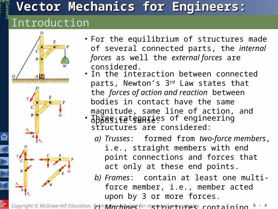
• For the equilibrium of structures made of several connected parts, the internal forces as well the external forces are considered.
• In the interaction between connected parts, Newton’s 3rd Law states that the forces of action and reaction between bodies in contact have the same magnitude, same line of action, and opposite sense.
• Three categories of engineering structures are considered:
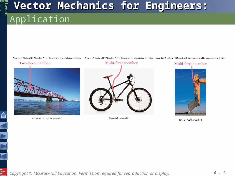
a) Trusses: formed from two-force members, i.e., straight members with end point connections and forces that act only at these end points.
b) Frames: contain at least one multi-force member, i.e., member acted upon by 3 or more forces.
c) Machines: structures containing moving parts designed to transmit and modify forces.
Copyright © McGraw-Hill Education. Permission required for reproduction or display.
Vector Mechanics for Engineers: StaticsVector Mechanics for Engineers: Statics
Ele
ve
nt
hEd
ition
Definition of a Truss
6 - 5
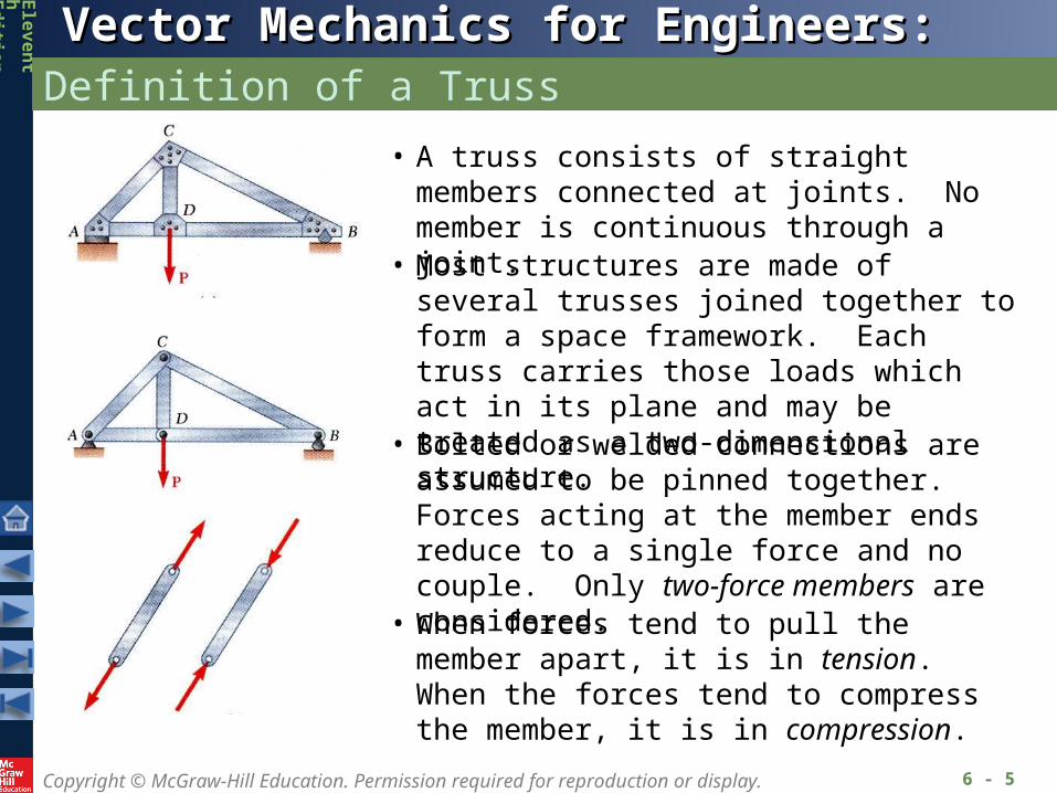
• A truss consists of straight members connected at joints. No member is continuous through a joint.
• Bolted or welded connections are assumed to be pinned together. Forces acting at the member ends reduce to a single force and no couple. Only two-force members are considered.
• Most structures are made of several trusses joined together to form a space framework. Each truss carries those loads which act in its plane and may be treated as a two-dimensional structure.
• When forces tend to pull the member apart, it is in tension. When the forces tend to compress the member, it is in compression.
Copyright © McGraw-Hill Education. Permission required for reproduction or display.
Vector Mechanics for Engineers: StaticsVector Mechanics for Engineers: Statics
Ele
ve
nt
hEd
ition
Definition of a Truss
6 - 6
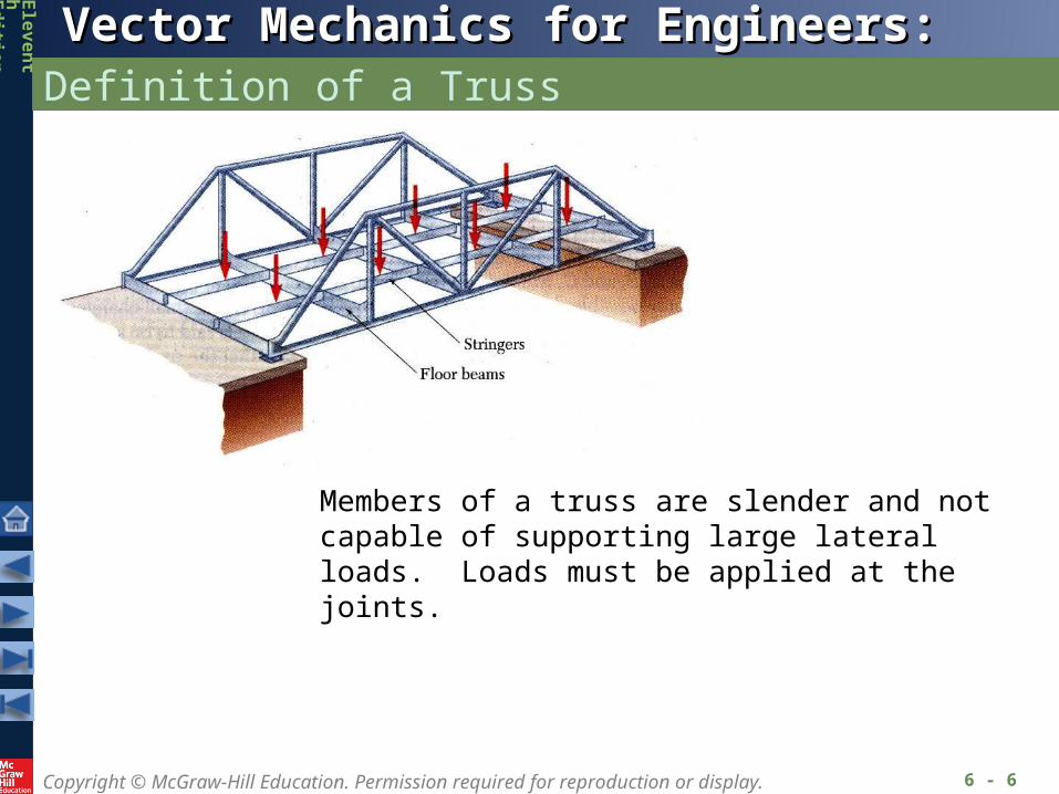
Members of a truss are slender and not capable of supporting large lateral loads. Loads must be applied at the joints.
Copyright © McGraw-Hill Education. Permission required for reproduction or display.
Vector Mechanics for Engineers: StaticsVector Mechanics for Engineers: Statics
Ele
ve
nt
hEd
ition
Definition of a Truss
6 - 7
Copyright © McGraw-Hill Education. Permission required for reproduction or display.
Vector Mechanics for Engineers: StaticsVector Mechanics for Engineers: Statics
Ele
ve
nt
hEd
ition
Simple Trusses
6 - 8
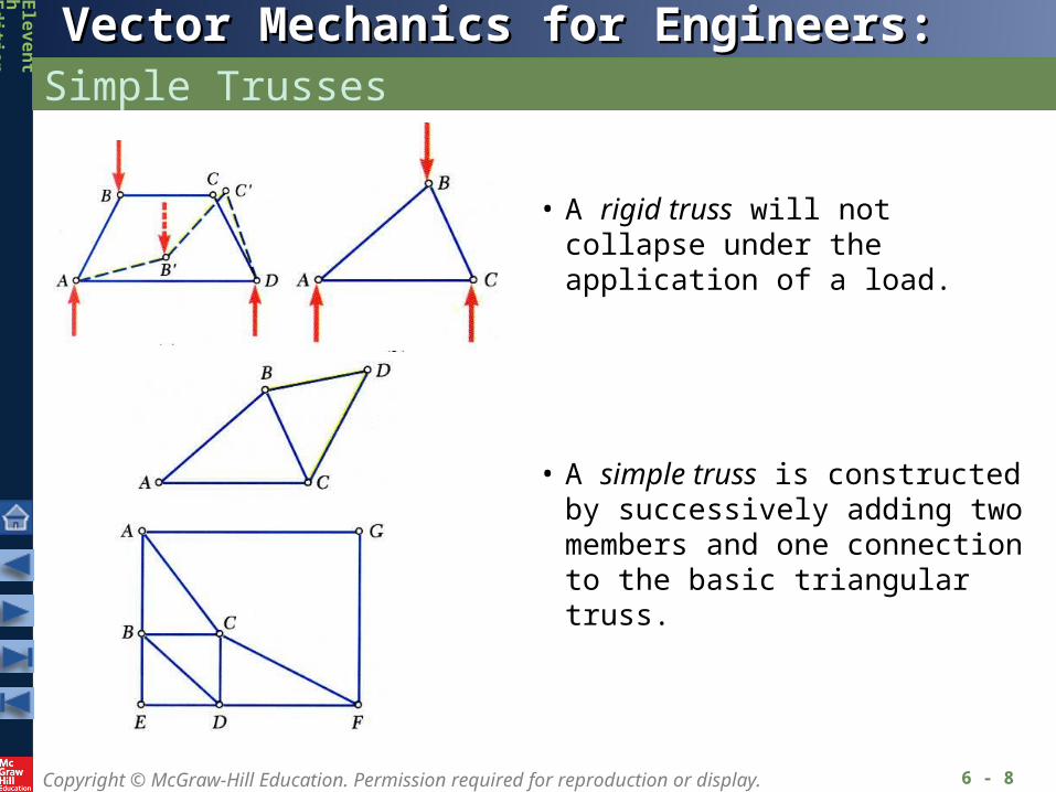
• A rigid truss will not collapse under the application of a load.
• A simple truss is constructed by successively adding two members and one connection to the basic triangular truss.
Copyright © McGraw-Hill Education. Permission required for reproduction or display.
Vector Mechanics for Engineers: StaticsVector Mechanics for Engineers: Statics
Ele
ve
nt
hEd
ition
Method of Joints
6 - 9
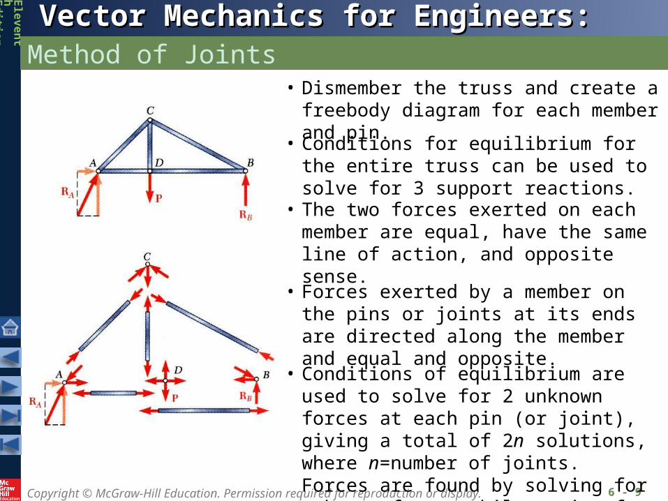
• Dismember the truss and create a freebody diagram for each member and pin.
• The two forces exerted on each member are equal, have the same line of action, and opposite sense.
• Forces exerted by a member on the pins or joints at its ends are directed along the member and equal and opposite.
• Conditions of equilibrium are used to solve for 2 unknown forces at each pin (or joint), giving a total of 2n solutions, where n=number of joints. Forces are found by solving for unknown forces while moving from joint to joint sequentially.
• Conditions for equilibrium for the entire truss can be used to solve for 3 support reactions.
Copyright © McGraw-Hill Education. Permission required for reproduction or display.
Vector Mechanics for Engineers: StaticsVector Mechanics for Engineers: Statics
Ele
ve
nt
hEd
ition
Joints Under Special Loading Conditions
6 - 10
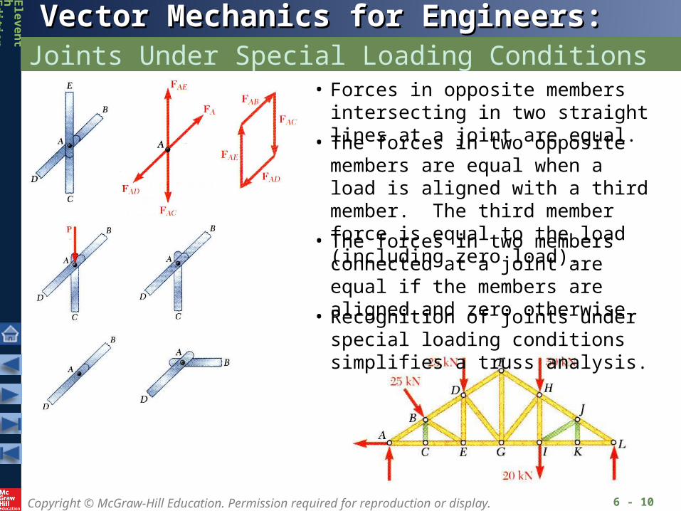
• Forces in opposite members intersecting in two straight lines at a joint are equal.
• The forces in two opposite members are equal when a load is aligned with a third member. The third member force is equal to the load (including zero load).
• The forces in two members connected at a joint are equal if the members are aligned and zero otherwise.
• Recognition of joints under special loading conditions simplifies a truss analysis.
Copyright © McGraw-Hill Education. Permission required for reproduction or display.
Vector Mechanics for Engineers: StaticsVector Mechanics for Engineers: Statics
Ele
ve
nt
hEd
ition
Space Trusses
6 - 11
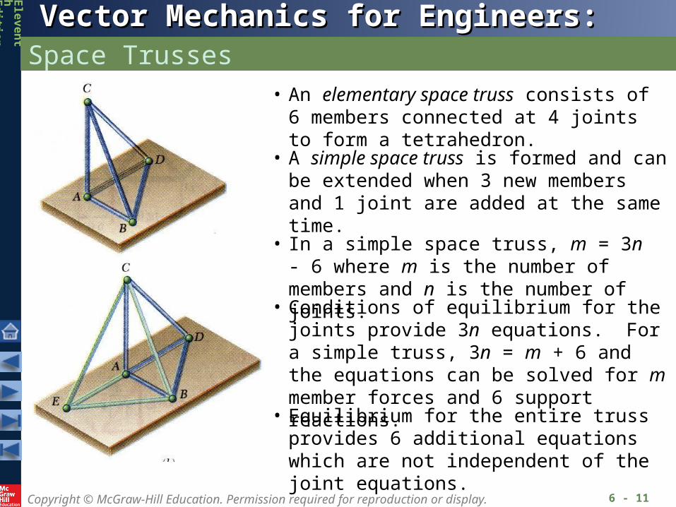
• An elementary space truss consists of 6 members connected at 4 joints to form a tetrahedron.
• A simple space truss is formed and can be extended when 3 new members and 1 joint are added at the same time.
• Equilibrium for the entire truss provides 6 additional equations which are not independent of the joint equations.
• In a simple space truss, m = 3n - 6 where m is the number of members and n is the number of joints.
• Conditions of equilibrium for the joints provide 3n equations. For a simple truss, 3n = m + 6 and the equations can be solved for m member forces and 6 support reactions.
Copyright © McGraw-Hill Education. Permission required for reproduction or display.
Vector Mechanics for Engineers: StaticsVector Mechanics for Engineers: Statics
Ele
ve
nt
hEd
ition
Sample Problem 6.1
6 - 12
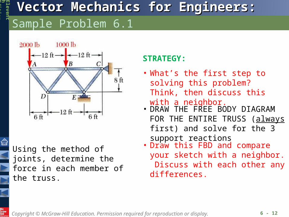
Using the method of joints, determine the force in each member of the truss.
STRATEGY:
• What’s the first step to solving this problem? Think, then discuss this with a neighbor.
• DRAW THE FREE BODY DIAGRAM FOR THE ENTIRE TRUSS (always first) and solve for the 3 support reactions
• Draw this FBD and compare your sketch with a neighbor. Discuss with each other any differences.

Copyright © McGraw-Hill Education. Permission required for reproduction or display.
Vector Mechanics for Engineers: StaticsVector Mechanics for Engineers: Statics
Ele
ve
nt
hEd
ition
Sample Problem 6.1
6 - 13
MODELING and ANALYSIS:
• Based on a free body diagram of the entire truss, solve the 3 equilibrium equations for the reactions at E and C.
ft 6ft 12lb 1000ft 24lb 2000
0
E
MC
lb 000,10E
xx CF 0 0xC
yy CF lb 10,000 lb 1000 - lb 20000
lb 7000yC
• Looking at the FBD, which “sum of moments” equation could you apply in order to find one of the unknown reactions with just this one equation?
• Next, apply the remaining equilibrium conditions to find the remaining 2 support reactions.
Copyright © McGraw-Hill Education. Permission required for reproduction or display.
Vector Mechanics for Engineers: StaticsVector Mechanics for Engineers: Statics
Ele
ve
nt
hEd
ition
Sample Problem 6.1
6 - 14
534
lb 2000 ADAB FF
CF
TF
AD
AB
lb 2500
lb 1500
FDB FDA
FDE 2 35 FDA CF
TF
DE
DB
lb 3000
lb 2500
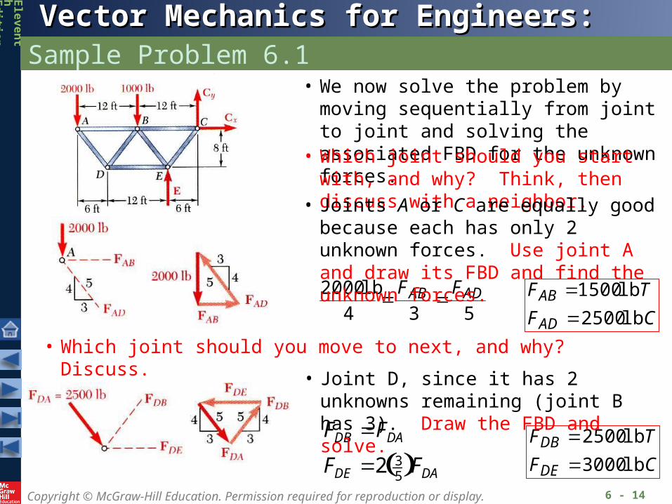
• We now solve the problem by moving sequentially from joint to joint and solving the associated FBD for the unknown forces.
• Which joint should you start with, and why? Think, then discuss with a neighbor.
• Joints A or C are equally good because each has only 2 unknown forces. Use joint A and draw its FBD and find the unknown forces.
• Which joint should you move to next, and why? Discuss.
• Joint D, since it has 2 unknowns remaining (joint B has 3). Draw the FBD and solve.
Copyright © McGraw-Hill Education. Permission required for reproduction or display.
Vector Mechanics for Engineers: StaticsVector Mechanics for Engineers: Statics
Ele
ve
nt
hEd
ition
Sample Problem 6.1
6 - 15
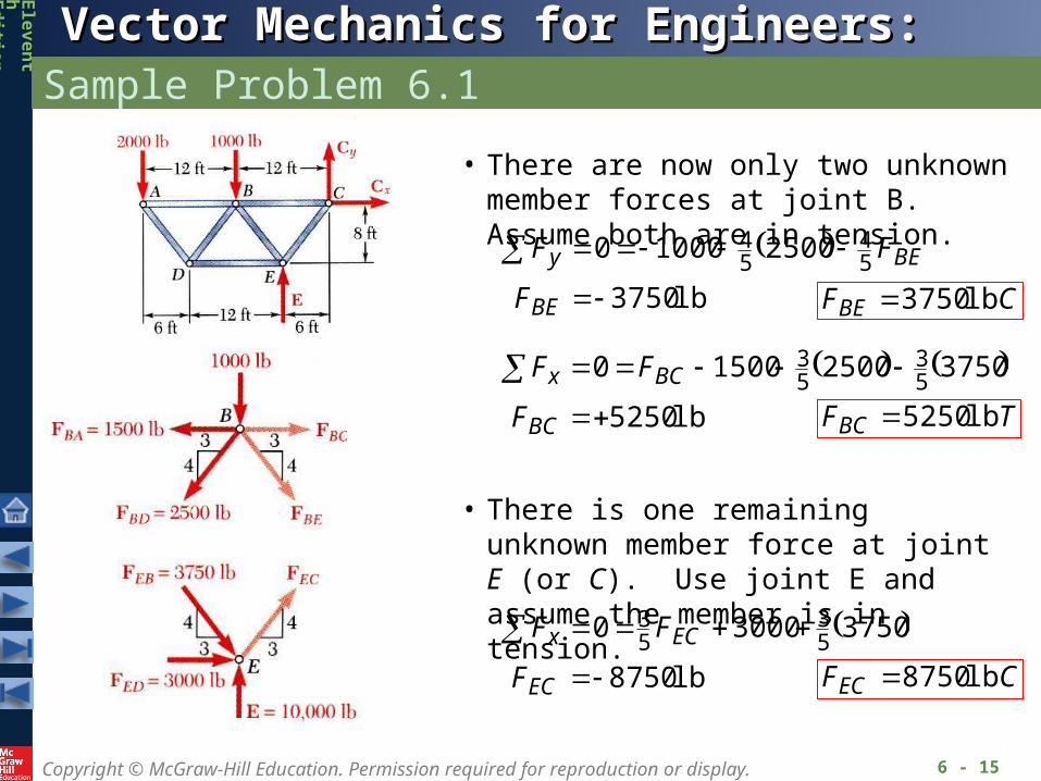
• There are now only two unknown member forces at joint B. Assume both are in tension.
lb 3750
25001000054
54
BE
BEy
F
FF
CFBE lb 3750
lb 5250
375025001500053
53
BC
BCx
F
FF
TFBC lb 5250
• There is one remaining unknown member force at joint E (or C). Use joint E and assume the member is in tension.
lb 8750
37503000053
53
EC
ECx
F
FF
CFEC lb 8750
Copyright © McGraw-Hill Education. Permission required for reproduction or display.
Vector Mechanics for Engineers: StaticsVector Mechanics for Engineers: Statics
Ele
ve
nt
hEd
ition
Sample Problem 6.1
6 - 16
checks 087507000
checks 087505250
54
53
y
x
F
F
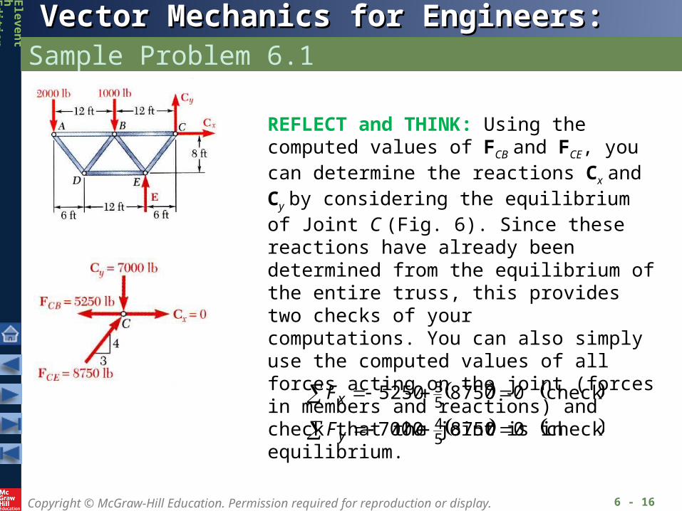
REFLECT and THINK: Using the computed values of FCB and FCE, you can determine the reactions Cx and Cy by considering the equilibriumof Joint C (Fig. 6). Since these reactions have already been determined from the equilibrium of the entire truss, this provides two checks of yourcomputations. You can also simply use the computed values of all forces acting on the joint (forces in members and reactions) and check that the joint is in equilibrium.
Copyright © McGraw-Hill Education. Permission required for reproduction or display.
Vector Mechanics for Engineers: StaticsVector Mechanics for Engineers: Statics
Ele
ve
nt
hEd
ition
Method of Sections
6 - 17
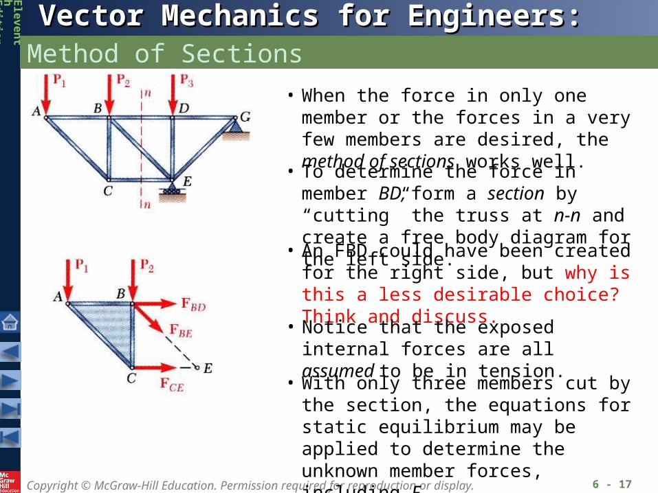
• When the force in only one member or the forces in a very few members are desired, the method of sections works well.
• To determine the force in member BD, form a section by “cutting” the truss at n-n and create a free body diagram for the left side.
• With only three members cut by the section, the equations for static equilibrium may be applied to determine the unknown member forces, including FBD.
• An FBD could have been created for the right side, but why is this a less desirable choice? Think and discuss.
• Notice that the exposed internal forces are all assumed to be in tension.
Copyright © McGraw-Hill Education. Permission required for reproduction or display.
Vector Mechanics for Engineers: StaticsVector Mechanics for Engineers: Statics
Ele
ve
nt
hEd
ition
Method of Sections
6 - 18
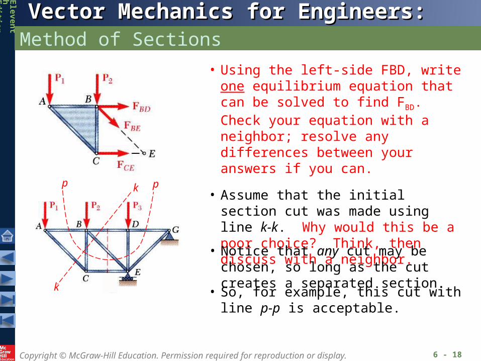
• Using the left-side FBD, write one equilibrium equation that can be solved to find FBD. Check your equation with a neighbor; resolve any differences between your answers if you can.
• So, for example, this cut with line p-p is acceptable.
• Assume that the initial section cut was made using line k-k. Why would this be a poor choice? Think, then discuss with a neighbor.
• Notice that any cut may be chosen, so long as the cut creates a separated section.
k
k
pp
Copyright © McGraw-Hill Education. Permission required for reproduction or display.
Vector Mechanics for Engineers: StaticsVector Mechanics for Engineers: Statics
Ele
ve
nt
hEd
ition
Trusses Made of Several Simple Trusses
6 - 19
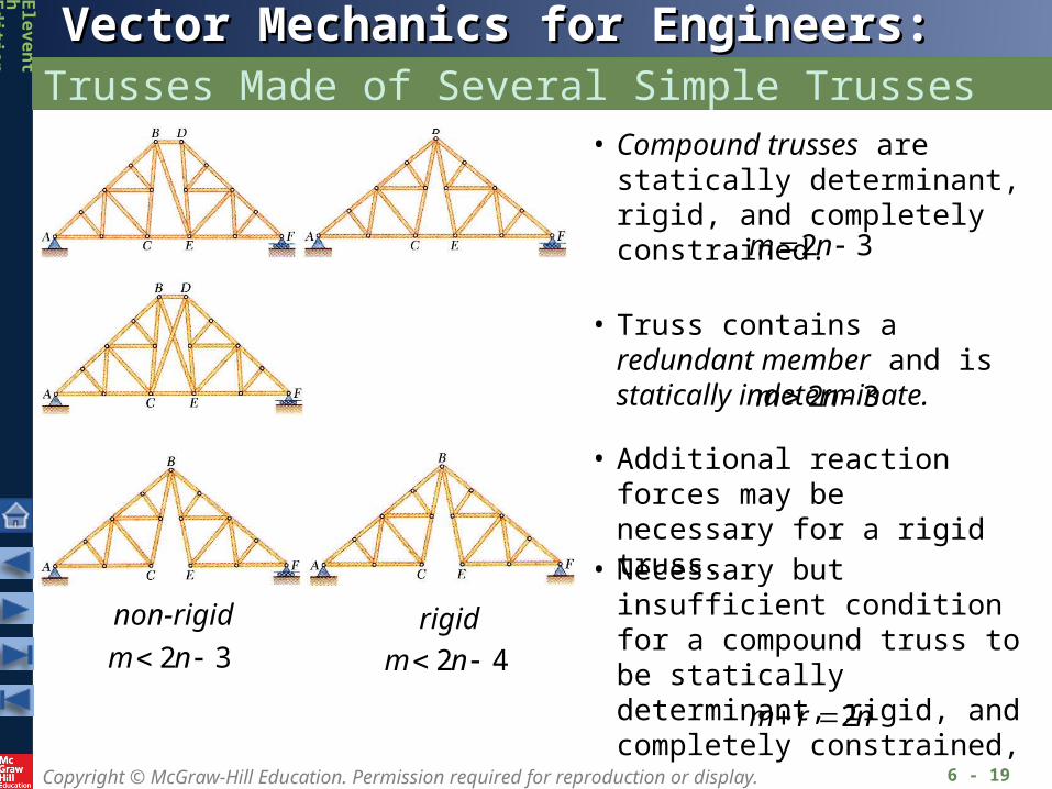
• Compound trusses are statically determinant, rigid, and completely constrained.
32 nm
• Truss contains a redundant member and is statically indeterminate.
32 nm
• Necessary but insufficient condition for a compound truss to be statically determinant, rigid, and completely constrained,
nrm 2
non-rigid rigid32 nm
• Additional reaction forces may be necessary for a rigid truss.
42 nm
Copyright © McGraw-Hill Education. Permission required for reproduction or display.
Vector Mechanics for Engineers: StaticsVector Mechanics for Engineers: Statics
Ele
ve
nt
hEd
ition
Sample Problem 6.3
6 - 20
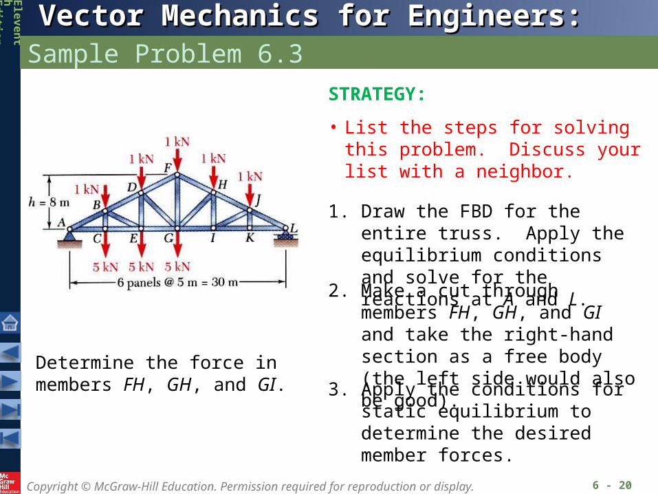
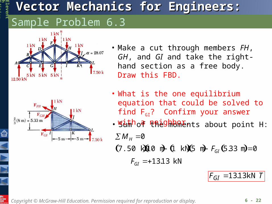
Determine the force in members FH, GH, and GI.
STRATEGY:
• List the steps for solving this problem. Discuss your list with a neighbor.
1. Draw the FBD for the entire truss. Apply the equilibrium conditions and solve for the reactions at A and L.
3. Apply the conditions for static equilibrium to determine the desired member forces.
2. Make a cut through members FH, GH, and GI and take the right-hand section as a free body (the left side would also be good).
Copyright © McGraw-Hill Education. Permission required for reproduction or display.
Vector Mechanics for Engineers: StaticsVector Mechanics for Engineers: Statics
Ele
ve
nt
hEd
ition
Sample Problem 6.3
6 - 21
MODELING and ANALYSIS:
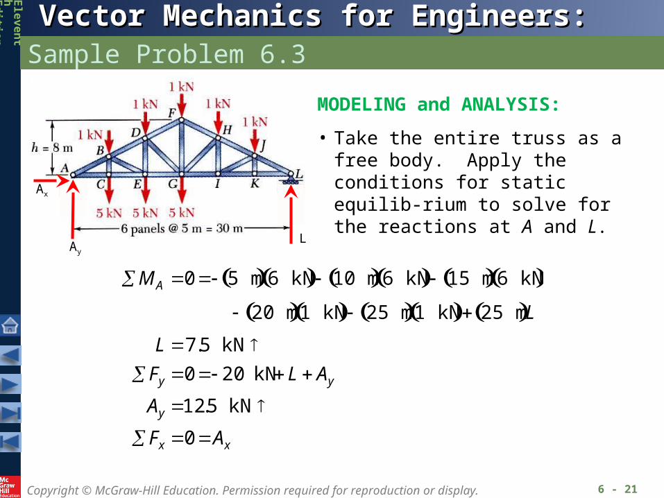
• Take the entire truss as a free body. Apply the conditions for static equilib-rium to solve for the reactions at A and L.
MA 0 5 m 6 kN 10 m 6 kN 15 m 6 kN 20 m 1 kN 25 m 1 kN 25 m L
L 7.5 kN Fy 0 20 kN L Ay
Ay 12.5 kN
Fx 0 Ax
LAy
Ax
Copyright © McGraw-Hill Education. Permission required for reproduction or display.
Vector Mechanics for Engineers: StaticsVector Mechanics for Engineers: Statics
Ele
ve
nt
hEd
ition
Sample Problem 6.3
6 - 22
• Make a cut through members FH, GH, and GI and take the right-hand section as a free body. Draw this FBD.
M H 0
7.50 kN 10 m 1 kN 5 m FGI 5.33 m 0
FGI 13.13 kN
• Sum of the moments about point H:
TFGI kN 13.13
• What is the one equilibrium equation that could be solved to find FGI? Confirm your answer with a neighbor.
Copyright © McGraw-Hill Education. Permission required for reproduction or display.
Vector Mechanics for Engineers: StaticsVector Mechanics for Engineers: Statics
Ele
ve
nt
hEd
ition
Sample Problem 6.3
6 - 23
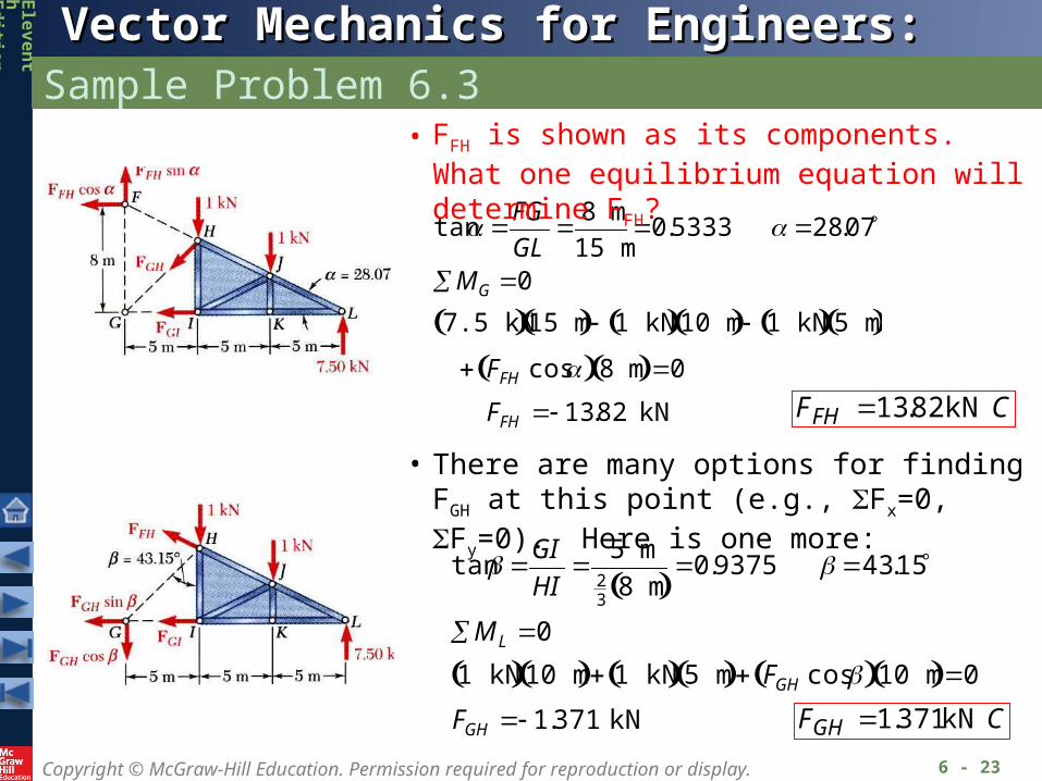
tan FG
GL 8 m
15 m0.5333 28.07
MG 0
7.5 kN 15 m 1 kN 10 m 1 kN 5 m FFH cos 8 m 0
FFH 13.82 kN CFFH kN 82.13
tan GI
HI 5 m
23
8 m 0.9375 43.15
ML 0
1 kN 10 m 1 kN 5 m FGH cos 10 m 0
FGH 1.371 kN CFGH kN 371.1
• FFH is shown as its components. What one equilibrium equation will determine FFH?
• There are many options for finding FGH at this point (e.g., Fx=0, Fy=0). Here is one more:
Copyright © McGraw-Hill Education. Permission required for reproduction or display.
Vector Mechanics for Engineers: StaticsVector Mechanics for Engineers: Statics
Ele
ve
nt
hEd
ition
Sample Problem 6.3
2 - 24
REFLECT and THINK:
Sometimes you should resolve a force intocomponents to include it in the equilibrium equations. By first sliding this force along its line of action to a more strategic point, you might eliminate one of its components from a moment equilibrium equation.

Copyright © McGraw-Hill Education. Permission required for reproduction or display.
Vector Mechanics for Engineers: StaticsVector Mechanics for Engineers: Statics
Ele
ve
nt
hEd
ition
Analysis of a Frame
6 - 25
• Frames and machines are structures with at least one multiforce (>2 forces) member. Frames are designed to support loads and are usually stationary. Machines contain moving parts and transmit and modify forces.
• A free body diagram of the complete frame is used to determine the external forces acting on the frame.
• Internal forces are determined by dismembering the frame and creating free-body diagrams for each component.
• Forces between connected components are equal, have the same line of action, and opposite sense.
• Forces on two force members have known lines of action but unknown magnitude and sense.
• Forces on multiforce members have unknown magnitude and line of action. They must be represented with two unknown components.
Copyright © McGraw-Hill Education. Permission required for reproduction or display.
Vector Mechanics for Engineers: StaticsVector Mechanics for Engineers: Statics
Ele
ve
nt
hEd
ition
Frames That Collapse Without Supports
6 - 26
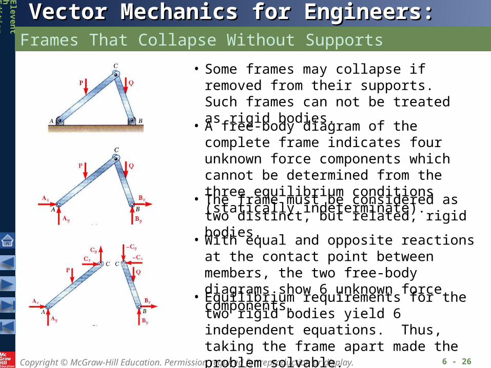
• Some frames may collapse if removed from their supports. Such frames can not be treated as rigid bodies.
• A free-body diagram of the complete frame indicates four unknown force components which cannot be determined from the three equilibrium conditions (statically indeterminate).
• The frame must be considered as two distinct, but related, rigid bodies.
• With equal and opposite reactions at the contact point between members, the two free-body diagrams show 6 unknown force components.
• Equilibrium requirements for the two rigid bodies yield 6 independent equations. Thus, taking the frame apart made the problem solvable.
Copyright © McGraw-Hill Education. Permission required for reproduction or display.
Vector Mechanics for Engineers: StaticsVector Mechanics for Engineers: Statics
Ele
ve
nt
hEd
ition
Sample Problem 6.4
6 - 27
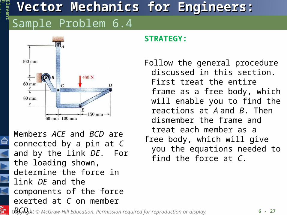
Members ACE and BCD are connected by a pin at C and by the link DE. For the loading shown, determine the force in link DE and the components of the force exerted at C on member BCD.
STRATEGY:
Follow the general procedure discussed in this section. First treat the entire frame as a free body, which will enable you to find the reactions at A and B. Then dismember the frame and treat each member as a
free body, which will give you the equations needed to find the force at C.
Copyright © McGraw-Hill Education. Permission required for reproduction or display.
Vector Mechanics for Engineers: StaticsVector Mechanics for Engineers: Statics
Ele
ve
nt
hEd
ition
Sample Problem 6.4
6 - 28
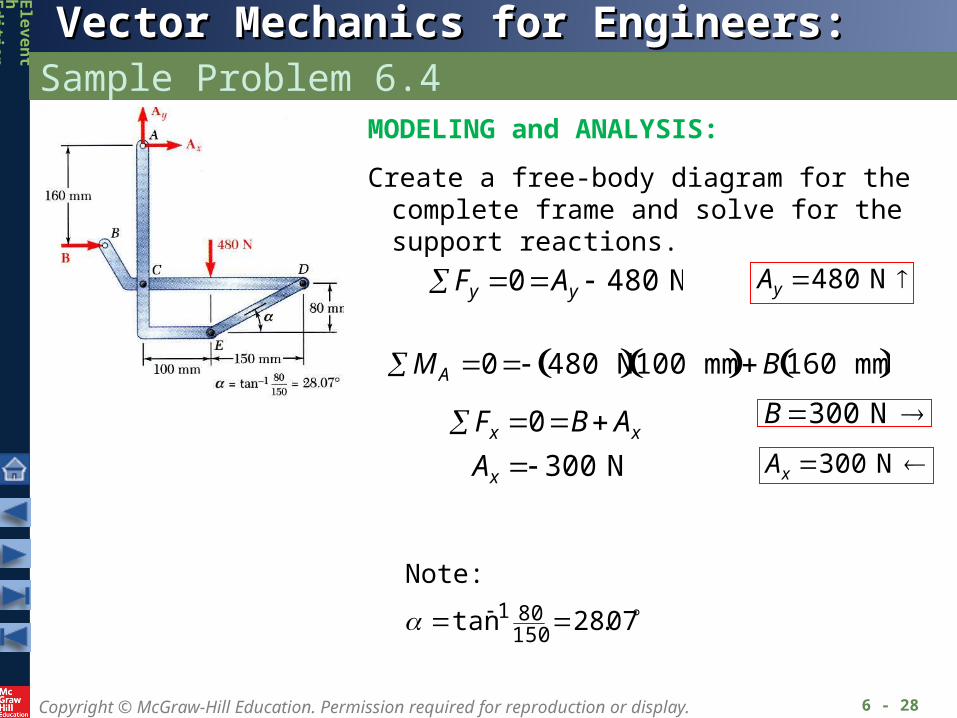
MODELING and ANALYSIS:
Create a free-body diagram for the complete frame and solve for the support reactions.
Fy 0 Ay 480 N
Ay 480 N
MA 0 480 N 100 mm B 160 mm
B 300 N
Fx 0 B Ax
Ax 300 N
Ax 300 N
07.28tan150801
Note:
Copyright © McGraw-Hill Education. Permission required for reproduction or display.
Vector Mechanics for Engineers: StaticsVector Mechanics for Engineers: Statics
Ele
ve
nt
hEd
ition
Sample Problem 6.4
6 - 29
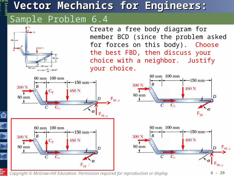
Create a free body diagram for member BCD (since the problem asked for forces on this body). Choose the best FBD, then discuss your choice with a neighbor. Justify your choice.
FDE,x
FDE,y
FDE
FDE
FDE,x
FDE,y
Copyright © McGraw-Hill Education. Permission required for reproduction or display.
Vector Mechanics for Engineers: StaticsVector Mechanics for Engineers: Statics
Ele
ve
nt
hEd
ition
Sample Problem 6.4
6 - 30
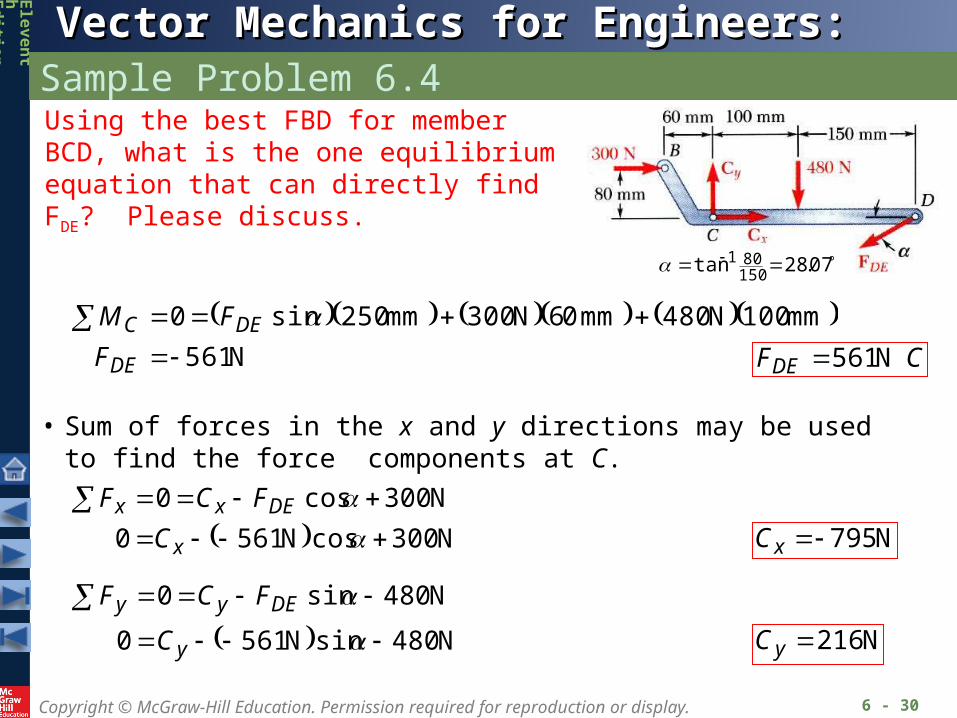
N 561
mm 100N 480mm 06N 300mm 250sin0
DE
DEC
F
FM CFDE N 561
• Sum of forces in the x and y directions may be used to find the force components at C.
N 300cosN 561 0
N 300cos0
x
DExx
C
FCF
N 795xC
N 480sinN 5610
N 480sin0
y
DEyy
C
FCF
N 216yC
Using the best FBD for member BCD, what is the one equilibrium equation that can directly find FDE? Please discuss.
07.28tan150801
Copyright © McGraw-Hill Education. Permission required for reproduction or display.
Vector Mechanics for Engineers: StaticsVector Mechanics for Engineers: Statics
Ele
ve
nt
hEd
ition
Sample Problem 6.4
6 - 31
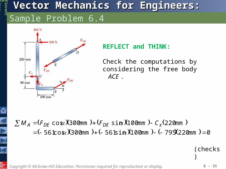
REFLECT and THINK:
Check the computations byconsidering the free body ACE .
0mm 220795mm 100sin561mm 300cos561
mm 220mm 100sinmm 300cos
xDEDEA CFFM
(checks)
Copyright © McGraw-Hill Education. Permission required for reproduction or display.
Vector Mechanics for Engineers: StaticsVector Mechanics for Engineers: Statics
Ele
ve
nt
hEd
ition
Machines
6 - 32
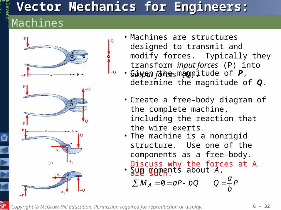
• Machines are structures designed to transmit and modify forces. Typically they transform input forces (P) into output forces (Q).
• Given the magnitude of P, determine the magnitude of Q.
• Create a free-body diagram of the complete machine, including the reaction that the wire exerts.
• The machine is a nonrigid structure. Use one of the components as a free-body. Discuss why the forces at A are such.
• Sum moments about A,
Pb
aQbQaPM A 0