static structural system duplicating static structural · calculate by hand the deflection of the...
TRANSCRIPT

ES 230 Strengths – Intro to Finite Element Modeling & Analysis Homework Assignment 3
The third homework problem involves modeling and analyzing a nine-bar truss to determine forces, stresses and deformations. You will also extend your use of the Direct Optimization Tool you tried out in the 3rd Tutorial. After running a basic analysis of the truss, you will use Direct Optimization to help you determine the truss dimensions needed to obtain a specific end deformation and also the cross-section thickness required to meet specific stress limits.
Description of Truss Model For this homework problem you will use your skills with 1D Line Elements to model and analysis a nine-bar truss. The geometry and topology of the truss is provided below. There is a pin support at Joint B and a roller support at Joint A. A concentrated load of 4000 lb is applied at Joint E. All of the truss members are made of Lafayette Aluminum and each has the same square tube cross-sections – an 1”x1”x1/8” section. Based on your knowledge of the Method of Joints and/or the Method of Sections you can determine the internal forces in all members of this truss by hand. However, you cannot yet calculate by hand the deflection of the truss under the load applied. Later on in your courses you will learn the Method of Virtual Work and other analysis methods that will allow you to calculate deflections of trusses by hand. However, you may not want to do this by hand since you will be able to use ANSYS to do this for you!
Starting the Homework Problem To start this homework, open up a new Static Structure analysis block from the Analysis Systems menu on the left-hand side (LHS). Since the geometry of the truss layout and the truss member cross-section is different for this problem, you should just create a new Static Structural System in the ANSYS workspace instead of Duplicating a previous model and trying to make the many changes needed. Drag a new Static Structural System into the workspace to begin the truss modelling process.
Click on the Engineering Data cell to open that view and to use Import ‘Lafayette Aluminum’ material to create a new material in the model. Once Lafayette Aluminum is imported, make sure to set it as the Default Material as done in the previous tutorial. Also check that the Units are in US Customary units and continue to check the Units at every step!
30 in. 30 in.
30 in.
A
B
C
D
E
F
4000 lb
1”x1”x 1/8”
Cross‐Section
Identify the Process for Creating the Truss Geometry and Model
Draw the Bar Elements required to create the Truss Layout and define the Square Tube Cross-Section in the DesignModeler window You will use 1D Line Elements to model each one of the truss members. Therefore you can create one Sketch that has nine 1D Line Elements drawn and dimensioned in it, instead of just the one 1D Line Element you defined for the cantilever beam in the 2nd Tutorial. Once you have the Sketch created and the line lengths dimensioned correctly, you can assign a square tube cross-section to all of the Line Elements. The Square Tube cross-section itself can be drawn using the same process that you used to draw the I-shaped cross-section for the cantilever beam in the 2nd Tutorial.
Assign the Boundary Support Conditions and the Concentrated Load in the Mechanical Model window You will be able to assign the Pin and Roller type support conditions to Joint B and Joint A, respectively. You will be able to assign a Force to Joint E that has a Y-component of -4000 lb.
Setup the Result Viewers and the Solve the Model in the Mechanical Model window You will want to setup Viewers in order to see the analysis results for Vertical Deflection, Axial Force, and Stress.
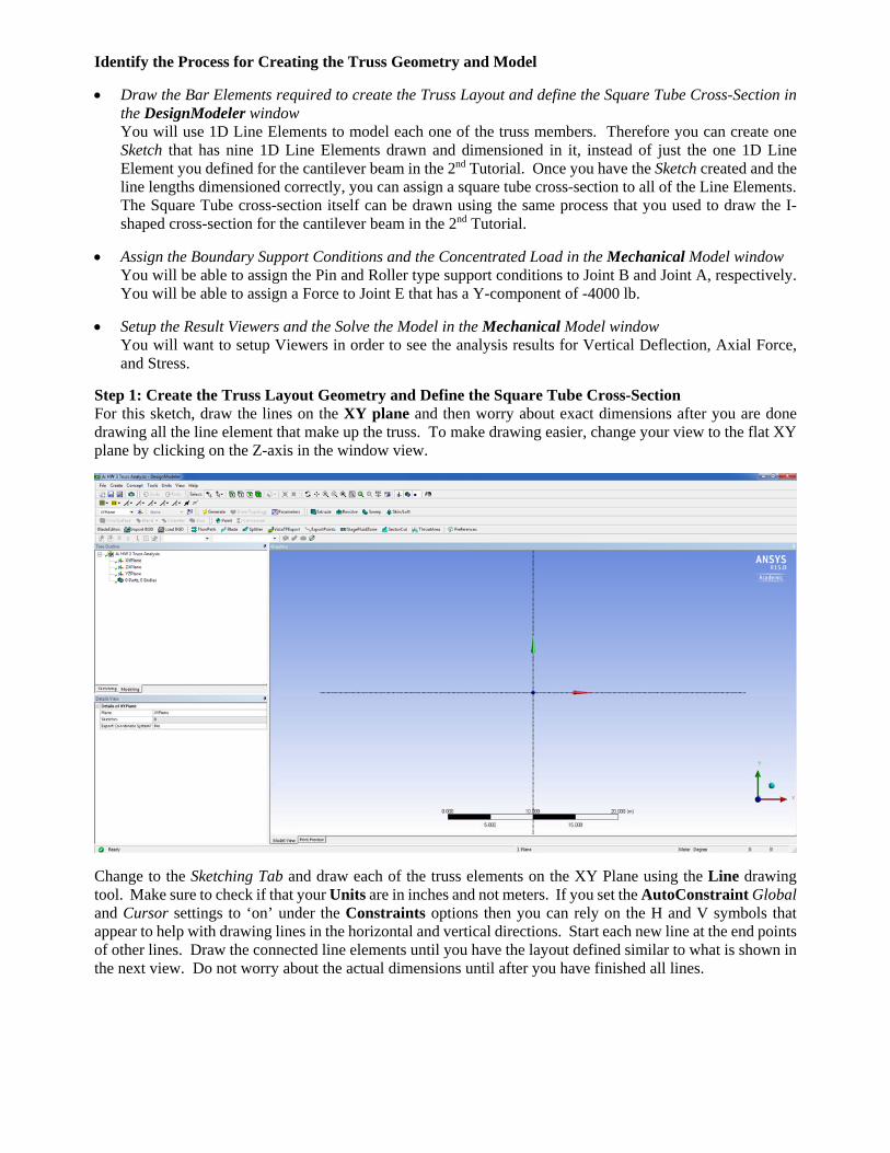
Step 1: Create the Truss Layout Geometry and Define the Square Tube Cross-Section For this sketch, draw the lines on the XY plane and then worry about exact dimensions after you are done drawing all the line element that make up the truss. To make drawing easier, change your view to the flat XY plane by clicking on the Z-axis in the window view.
Change to the Sketching Tab and draw each of the truss elements on the XY Plane using the Line drawing tool. Make sure to check if that your Units are in inches and not meters. If you set the AutoConstraint Global and Cursor settings to ‘on’ under the Constraints options then you can rely on the H and V symbols that appear to help with drawing lines in the horizontal and vertical directions. Start each new line at the end points of other lines. Draw the connected line elements until you have the layout defined similar to what is shown in the next view. Do not worry about the actual dimensions until after you have finished all lines.

Now add the correct Dimensions of 30” panel heights and 30” panel widths to the Sketch using the Vertical and Horizontal dimension tools. You only need to provide three dimension lines – two for the widths and one for the height of the truss. If the truss goes out of view during dimensioning you can use the F7 key to Zoom to Fit and bring it back into a full view.
Now change to the Modeling Tab and select the operation Concept->Lines From Sketches from the top toolbar. Click on the XY Plane Sketch1 leaf item in the LHS menu to select all of the lines drawn in the sketch at once. Then click Apply in the lower menu and then Generate in the top toolbar. You will now have created the LineBody defining the truss geometry as shown in the next view.

Now you need to create the square tube cross-section. Select the option Concept->Cross-Section->Rectangular Tube from the top toolbar to get a basic square tube cross-section that you can dimension.
The square tube cross-section has dimensions of 1”x1”x1/8” (width x height x thickness). Enter these dimensions as needed in the bottom LHS boxes of the cross-section Details View. You may need to change the thicknesses of the cross-section elements before you are allowed to change the height or width of the cross-section due to having to have a physical reality hold in the relative dimensions.

The last step for defining the Truss Geometry Layout and Cross-section is to assign the square tube cross-section to the LineBody geometry previously created. To do this click on the LineBody leaf in the LHS menu. A box highlighted in yellow will appear in the bottom LHS menu. Click on the highlighted box and use the pulldown menu to select the RectTube1 as the selected cross-section for the truss.
You can view the Truss in 3D by selecting View->Cross Section Solids from the top toolbar and then change to the ISO view. At this point Save your model.

Create the Mesh for the Model, which consists of 1D Beam (Line) Elements Open the Mechanical window by double clicking on the Model cell in the main ANSYS window. Right click on the Mesh leaf and select Generate Mesh. The default of Coarse mesh is just fine for this truss model.
Assign the Concentrated Load in the Mechanical Model window Assign a Force to Joint E that has a Y-component of -4000 lb. Use StaticStructural->Insert->Force and select the node corresponding to Joint E. Use components to give the force only a component in the negative Y axis direction. Use the Node selection tool from the top toolbar to help you select Joint E as the loaded node.
Assign Boundary Support Conditions and the Concentrated Load in the Mechanical Model window To assign the idealized pinned and roller support conditions you will need to use Displacement constraints since there are no predefined supports of this type in ANSYS. Displacement constraints require you to define whether there is a specific constraint on the displacement of a specific node in a specific axis direction (0 means that the node cannot move) or if there is no constraint on a displacement of a specific node in a specific

axis direction (free to move). Displacement constraints will not affect rotations that may occur at the node. This is okay for the truss model since a pin or roller support does not restrain rotation at the support.
Add a Pinned Support at Joint B – Not free to move in the X or Y axis direction. Select Static Structural->Insert->Displacement and edit the boxes in the bottom LHS to set the X and Y Component Displacements to 0. Leave the Z-axis direction as free. ANSYS will restrain this out-of-plane direction itself with weak springs for this truss problem to keep the truss from moving out-of-plane. After changing the values use the Node Selection tool to select Joint B in the view and hit Apply.
Add a Roller Support at Joint A – Not free to move in the X direction, but free to move (roll) in the Y direction Select Static Structural->Insert->Displacement and then edit the boxes in the bottom LHS to set the X Component Displacements to 0. Leave the Y and Z Components with Free. Then use the Node Selection tool

to select Joint A in the view and hit Apply. You can rename these Displacement constraints as Pin Support and Roller Support if you like.
Setup the Result Viewers and then Solve You will want to setup Viewers for Vertical Deflection (Displacement in the Y-direction), Axial Force, and Direct Stress using the Beam Tool. You can find these all under the Solution->Insert Viewer options.
Now Save your model and then Solve…. You can use View->Cross Section Solids (Geometry) to view the truss with 3D elements instead of line elements.

Homework 3 Assignment Part to Turn In – A), B) and C): Due Tuesday, Nov. 10th Turn in the following items in hard copy form (print out) for grading. To get good views of the ANSYS Results you may need to zoom in or rotate the axial bar in the window as needed.
A) Hand Calculations to turn in for the Truss Analysis Solve for the pin and roller support reactions and then calculate the axial force in each member of the truss
by hand using the Method of Joints and/or Method of Sections. Summarize your results on a sketch of the truss geometry. State if each truss member is in tension or compression.
Using the cross-sectional area of the square tube, calculate the stress in each member of the truss by hand. Show your stress results on the same sketch of the truss geometry provided above.
B) Screen Captured ANSYS analysis results to turn in for the Truss Analysis: Screen-capture and print-out a view showing results for the vertical deformation of the truss model. Make
sure you can clearly see the color variation along the truss and the color legend. Use the Min Probe to identify where the largest negative vertical deformation occurs on the truss. Also make sure to show the undeformed truss shape in your view. Circle the units on the printed copy.
Screen-capture and print-out views showing results for the axial force in the truss model. Make sure you can clearly see the color variation across the truss itself. Add one Probe value to each truss member to show its axial force in the view. Circle the units on each printed copy.
Screen-capture and print-out a view showing results for the Direct Stress (Axial Stress) using the Beam Tool. Make sure you can clearly see the color variation across the truss itself. Add one Probe value to each truss member to show its axial stress in the view. Circle the units on each printed copy.
C) Comparison of the Hand Calculations and ANSYS Analysis Results to turn in for the Truss Analysis: Compare the values of the axial force in each truss member calculated by hand with the values of the axial
forces in each truss member obtained from the ANSYS results. Discuss any difference in these values that may occur due to using beam elements for the ANSYS truss model instead of idealized pin-connected, two force members that form the basis of an ideal truss analysis run when using hand calculations.
Calculate the values of the axial stress in each truss member calculated by hand with the values of the Direct Stress (axial stress) obtained from the ANSYS results. Discuss any difference in these values.

Optimize the Truss Geometry Dimensions to Obtain a Specific End Deformation
Set the Height of the Truss as the single Input Design Variable for the Optimization Process: Open the Geometry view in DesignModeler and view the Modeling tab. Click on the Sketch leaf under the XY Plane and mark the checkbox for the Dimension V4 which is tied to the truss Height as a design parameter. Be careful not to select one of the truss width dimensions in the view. Click OK in the pop up dialog box to set the height of the truss as an Input Parameter.
Once you confirm there is a D in the box, change the view to the Mechanical window in order to select the Output Design Parameters.
Set the Vertical Deformation of the Truss as the Output Design Variable for the Optimization Process: Click on the Directional Deformation Viewer and then click in the checkbox for the Minimum Deformation. (You need to select the minimum because the vertical deformation value is negative for the negative Y direction in the results). A P will appear this box.

Now go to the main ANSYS window and double click on Parameter Set. In the menu provided check that one Input Design Variable and one Output Design Parameter have been defined. Change back to the Project tab to return to the main ANSYS window.
Drag a Direct Optimization box into the project space in the main ANSYS window.
Double Click on Optimization in the Direction Optimization menu to go to its viewer. Change the Optimization Method to NLPQL from Screening and then click on the Objectives and Constraint option to open the objective and constraint Table as done in the 3rd Tutorial. In the Table that appears on the upper RHS enter the text and select the values shown in the next view. Make sure the value is stated in this table as -0.6 not as 0.6.
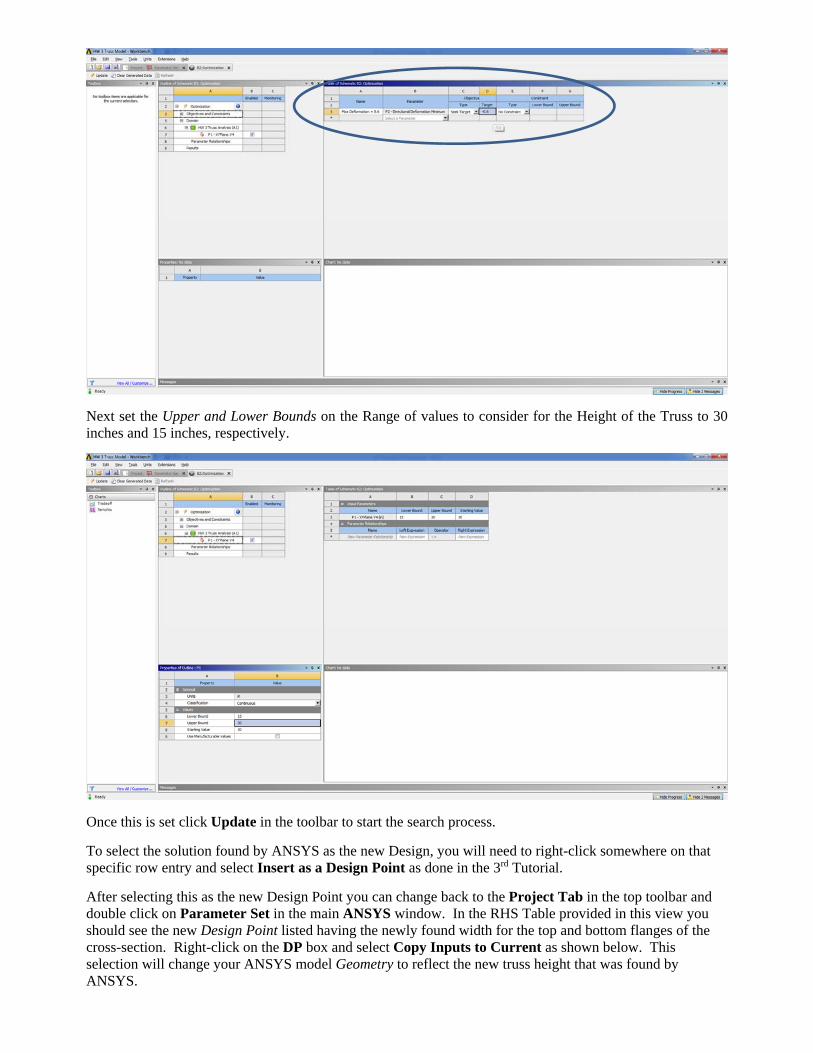
Next set the Upper and Lower Bounds on the Range of values to consider for the Height of the Truss to 30 inches and 15 inches, respectively.
Once this is set click Update in the toolbar to start the search process.
To select the solution found by ANSYS as the new Design, you will need to right-click somewhere on that specific row entry and select Insert as a Design Point as done in the 3rd Tutorial. After selecting this as the new Design Point you can change back to the Project Tab in the top toolbar and double click on Parameter Set in the main ANSYS window. In the RHS Table provided in this view you should see the new Design Point listed having the newly found width for the top and bottom flanges of the cross-section. Right-click on the DP box and select Copy Inputs to Current as shown below. This selection will change your ANSYS model Geometry to reflect the new truss height that was found by ANSYS.

Change back again to the Project Tab and double click on Geometry in your current project. Click OK for any popup windows that appear. In the DesignModeler change to the Sketching view and look at the dimension values for the truss. You see the optimized height value in listed.
Change back to the main ANSYS window and update the Model by right-clicking on Model and selecting Update. Then double-click on Model to open the Mechanical window. Right click on Solutions and select Solve to get the analysis results for the modified truss height design. If necessary use Clear Generated Results and then Solve. Using the result view for the Directional Deformation you can check to see that the 0.6 inch maximum deformation limit as set as an optimization constraint is meet by this new truss geometry. You can also view the Axial Forces in each of the truss members that results from the new truss depth found by ANSYS.
NEW TRUSS HEIGHT VALUE

Homework 3 Assignment Part to Turn In – D): Due Tuesday, Nov. 10th Turn in the following items in hard copy form (print out) for grading. To get good views of the ANSYS Results you may need to zoom in or rotate the axial bar in the window as needed.
D) Screen Captured ANSYS analysis results to turn in for the Truss Optimization: Report the optimized height value of the truss found by ANSYS through optimization. Screen-capture and print-out a view showing results for the vertical deformation of the optimized truss
model. Make sure you can clearly see the color variation along the truss and the color legend. Use the Min Probe to identify where the largest negative vertical deformation occurs on the truss. Also make sure to show the undeformed truss shape in your view. Circle the units on the printed copy.
Screen-capture and print-out views showing results for the axial force in the optimized truss model. Make sure you can clearly see the color variation across the truss itself. Add one Probe value to each truss member to show its axial force in the view. Circle the units on each printed copy.