“static & dynamic analysis of spur gear using … one of the design criteria.in this project,...
TRANSCRIPT
International Research Journal of Engineering and Technology (IRJET) e-ISSN: 2395-0056
Volume: 03 Issue: 01 | Jan-2016 www.irjet.net p-ISSN: 2395-0072
© 2016, IRJET | Impact Factor value: 4.45 | ISO 9001:2008 Certified Journal | Page 694
“Static & Dynamic Analysis of Spur Gear using Different Materials” M. KEERTHI1, K. SANDYA2, K. SRINIVAS3
1 PG Student, Mechanical Engineering, DVR & Dr. HS MIC College of Technology, Andhra Pradesh, INDIA 2 PG Student, Mechanical Engineering, DVR & Dr. HS MIC College of Technology, Andhra Pradesh ,INDIA
3 Associate Professor, Mechanical Engineering, DVR & Dr. HS MIC College of Technology, Andhra Pradesh, INDIA
---------------------------------------------------------------------***---------------------------------------------------------------------Abstract - Gear drive plays vital role in power transmission industries. Gears are usually subjected to fluctuating loads. Due to these loads bending and compressive stresses will be developed in the gears. While designing the gear it is very important to analyze the stresses for safety operation, and weight reduction of gear is also one of the design criteria.In this project, the spur gear is modeled in “SOLIDWORKS” and imported to “ANSYS” for static structural analysis and modal analysis. Static analysis is performed to determine the deformation and Von-mises stresses. Modal analysis is performed to determine the natural frequencies and mode shapes. The results were validated with theoretical calculations by Lewis equation. Analysis is done by considering different materials for gears like Structural Steel, Gray Cast Iron, Aluminium Alloy and Epoxy E Glass UD, and results are compared.
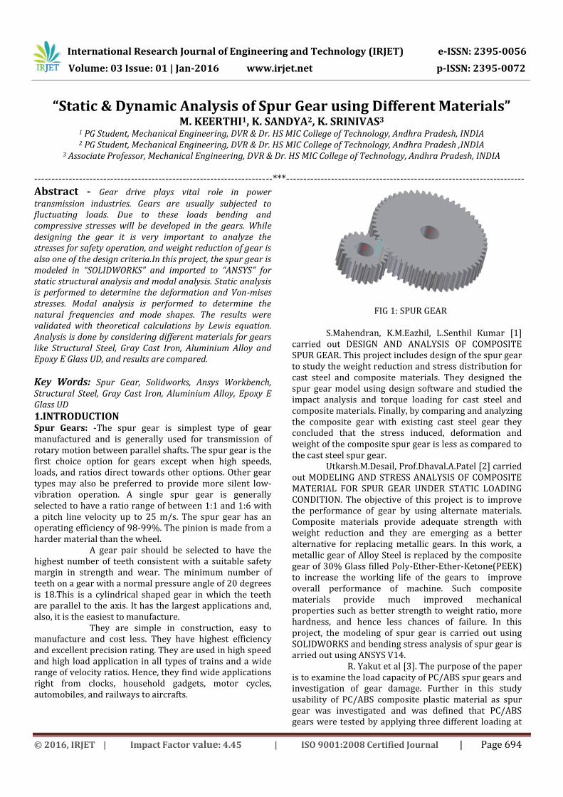
Key Words: Spur Gear, Solidworks, Ansys Workbench, Structural Steel, Gray Cast Iron, Aluminium Alloy, Epoxy E Glass UD 1.INTRODUCTION Spur Gears: -The spur gear is simplest type of gear manufactured and is generally used for transmission of rotary motion between parallel shafts. The spur gear is the first choice option for gears except when high speeds, loads, and ratios direct towards other options. Other gear types may also be preferred to provide more silent low-vibration operation. A single spur gear is generally selected to have a ratio range of between 1:1 and 1:6 with a pitch line velocity up to 25 m/s. The spur gear has an operating efficiency of 98-99%. The pinion is made from a harder material than the wheel. A gear pair should be selected to have the highest number of teeth consistent with a suitable safety margin in strength and wear. The minimum number of teeth on a gear with a normal pressure angle of 20 degrees is 18.This is a cylindrical shaped gear in which the teeth are parallel to the axis. It has the largest applications and, also, it is the easiest to manufacture. They are simple in construction, easy to manufacture and cost less. They have highest efficiency and excellent precision rating. They are used in high speed and high load application in all types of trains and a wide range of velocity ratios. Hence, they find wide applications right from clocks, household gadgets, motor cycles, automobiles, and railways to aircrafts.
FIG 1: SPUR GEAR
S.Mahendran, K.M.Eazhil, L.Senthil Kumar [1] carried out DESIGN AND ANALYSIS OF COMPOSITE SPUR GEAR. This project includes design of the spur gear to study the weight reduction and stress distribution for cast steel and composite materials. They designed the spur gear model using design software and studied the impact analysis and torque loading for cast steel and composite materials. Finally, by comparing and analyzing the composite gear with existing cast steel gear they concluded that the stress induced, deformation and weight of the composite spur gear is less as compared to the cast steel spur gear.
Utkarsh.M.Desail, Prof.Dhaval.A.Patel [2] carried out MODELING AND STRESS ANALYSIS OF COMPOSITE MATERIAL FOR SPUR GEAR UNDER STATIC LOADING CONDITION. The objective of this project is to improve the performance of gear by using alternate materials. Composite materials provide adequate strength with weight reduction and they are emerging as a better alternative for replacing metallic gears. In this work, a metallic gear of Alloy Steel is replaced by the composite gear of 30% Glass filled Poly-Ether-Ether-Ketone(PEEK) to increase the working life of the gears to improve overall performance of machine. Such composite materials provide much improved mechanical properties such as better strength to weight ratio, more hardness, and hence less chances of failure. In this project, the modeling of spur gear is carried out using SOLIDWORKS and bending stress analysis of spur gear is arried out using ANSYS V14. R. Yakut et al [3]. The purpose of the paper is to examine the load capacity of PC/ABS spur gears and investigation of gear damage. Further in this study usability of PC/ABS composite plastic material as spur gear was investigated and was defined that PC/ABS gears were tested by applying three different loading at
International Research Journal of Engineering and Technology (IRJET) e-ISSN: 2395-0056
Volume: 03 Issue: 01 | Jan-2016 www.irjet.net p-ISSN: 2395-0072
© 2016, IRJET | Impact Factor value: 4.45 | ISO 9001:2008 Certified Journal | Page 695
two different numbers of revolutions on the FZG experiment set. The experiment result summarized that the usage of PC/ABS materials brings an advantage in many industrial area because such materials are durable against flame, air, ultraviolet lights and holding lower moister than PA66 GFR 30 materials.The another result of this study was that good operating conditions are comprised at low numbers of revolution and the tooth loads. Further the suitable environmental condition must be revolutions and the tooth load for gears. PC/ABS gear should be preferred at low tooth and unwanted high power transmission. V. Siva Prasad et al [4]. This paper describes design and analysis of spur gear and it is proposed to substitute the metallic gears of sugarcane juice machine with polymer gears to reduce the weight and noise. A virtual model of spur gear was created in PRO-E, Model is imported in ANSYS 10.0 for analysis by applying normal load condition. The main purpose of this paper to analysis the different polymer gears namely nylon, polycarbonate and their viability checked with counterpart metallic gear like as cast iron. Concluding the study using the FEA methodology, it can be proved that the composite gears, if well designed and analysed, will give the useful properties like as a low cost, noise, weight, vibration and perform its operation similar to the metallic gears. Based on the static analysis Nylon gears are suitable for the application of sugarcane juice machine under limited load condition in comparison with cast iron spur gears. Vivek Karaveer et al [5]. This paper presents the stress analysis of mating teeth of the spur gear to find maximum contact stress in the gear tooth The results obtained from finite element analysis are compared with theoretical Hertz equation values. The spur gears are modeled and assembled in ANSYS DESIGN MODELER and stress analysis of Spur gear tooth is done by the ANSYS 14.5 software. It was found that the results from both Hertz equation and Finite Element Analysis are comparable. From the deformation pattern of steel and grey cast iron, it could be concluded that difference between the maximum values of steel and grey CI gear deformation is very less. Mahebub Vohra et al [6]. In this paper, Metallic material Cast iron and Non- Metallic material Nylon are investigated. The stress analysis of the lathe machine headstock gear box are analyzed by finite element analysis. Analytical bending stress is calculated by two formula Lewis formula and AGMA formula. Analytical results is compared with the finite element method result for validation. This study concludes that, finite element method software ANSYS have values of stress distribution were in good agreement with the theoretical results. Besides non metallic material can be used instead of metallic material because non metallic material provide extra benefits like less cost, self lubricating, low noise, low vibration and easy
manufacturing.
2. OBJECTIVES OF WORK: The objective of the project is to reduce the
stress distribution, deformation and weight of spur gear by using composite materials in the application of gear box. The designed composite spur gear is compared with the existing gear materials, such as structural steel, gray cast iron and aluminium alloy. The tool which is used to analyze the different spur gear materials is ANSYS. In this, the analysis of torque loading and stress induced are to be performed for the materials chosen. The final outputs of these analyses for all the materials are to be compared. From this comparison, the stress induced, deformation and weight for composite spur gear materials are to be less than that of the general spur gear materials.
3. PROJECT DESCRIPTION 3.1 Mathematical Model Calculations:
Model = TATA SUPER ACE Engine = TATA475 TCIC BSIII) Torque(T) = 135.24 N.m Speed(N) = 2500 rpm
Power(P) = = 35405.74 W
= 35.40 kW Torque (T) = F×(d/2) Where, F-load, d- Pitch circle diameter (z×m=180mm) F = T/ (d/2) F = 135240 / 90 Load (F) = 1502.66 N Using Lewis equation, Tangential load, F =b×y×pc×σb pc =π×m = 31.41 mm y= Lewis form factor=0.134mm b = face width = 54mm
The maximum allowable stress= 8.7413N/mm2. Ultimate tensile strength for structural steel=460 MPa Ultimate tensile strength for composite=35 MPa Allowable stress for structural steel = ultimate tensile strength/3
= 460/3 = 153.33 N/mm2> 8.7413N/mm2 Allowable stress for composite = ultimate tensile
strength/3= 35/3 = 11.66 N/mm2>8.7413N/mm2 So, the design is safe. 3.2.Calculations of Gear Tooth Properties: Module = D/Z = 180/18 = 10mm Pitch circle diameter (P.C.D) = Z×m = 18×10 = 180mm Base circle diameter (Db) = D cos α = 180×cos20 = 169.145mm Outside circle diameter = (Z+2) ×m= (18+2) ×10 = 200mm Clearance = circular pitch/20 = 31.4/20 = 1.57mm

International Research Journal of Engineering and Technology (IRJET) e-ISSN: 2395-0056
Volume: 03 Issue: 01 | Jan-2016 www.irjet.net p-ISSN: 2395-0072
© 2016, IRJET | Impact Factor value: 4.45 | ISO 9001:2008 Certified Journal | Page 696
Dedendum = Addendum + Clearance = 10+1.57 = 11.57mm Dedendum circle diameter = (P.C.D -2)×dedendum = (80-2) ×11.57= 156.86mm Fillet radius = Circular pitch/8 = 31.4/8 = 3.9mm Hole depth = 2.25×m = 2.25×10 = 22.5mm Thickness of the tooth = 1.571×10 = 15.71mm Face width (b) = 0.3×180= 54mm Center distance between two gears = 180mm Diametral pitch = Number of teeth/P.C.D= 18/180= 0.1mm
4. MATERIALS SELECTION: Structural Steel:
Density = 7850 kg/m3 Young modulus = 200 GPa Poisson’s ratio = 0.3 Ultimate Tensile Strength = 460 MPa Yield Tensile Strength = 250 MPa Bulk modulus = 166 GPa
Gray Cast Iron:
Density = 7200 kg/m3 Young modulus = 110 GPa Poisson’s ratio = 0.28 Ultimate Tensile Strength = 430 MPa Ultimate Compressive Strength = 820MPa Yield Tensile Strength = 276 MPa Bulk modulus = 83.3 GPa
Aluminium Alloy:
Density = 2770 kg/m3 Young modulus = 71 GPa Poisson’s ratio = 0.33 Ultimate Tensile Strength = 310 MPa Yield Tensile Strength = 280 MPa Bulk modulus = 69.6 GPa
Epoxy E Glass UD:
Density = 2000 kg/m3 Young modulus = 450 GPa (X Direction) = 100 GPa (Y& Z Directon) Poisson’s ratio = 0.3 ( XY & XZ) = 0.4 (YZ) Ultimate Tensile Strength = 1100 MPa ( X Direction) = 35 MPa ( Y&Z Direction)
The Spur Gear models are created by using Solid works software. The model is shown below:
Fig.2. Spur Gear model
This model is exported to HyperMesh to mesh the component with element size=0.001 and element type = trias The Number of Nodes formed=309591 Number of Elements=68448 Then, the meshed model is imported into ANSYS Workbench to conduct static structural analysis, modal analysis.
5. RESULTS & DISCUSSION: Analysis Results for Spur Gear in Various Materials:
Static Structural Analysis Torque, T= 135 N.m Structural Steel
Fig.3. Total deformation in structural steel at T=135 N.m
Fig.4. Von-mises stress in structural steel at T=135 N.m

International Research Journal of Engineering and Technology (IRJET) e-ISSN: 2395-0056
Volume: 03 Issue: 01 | Jan-2016 www.irjet.net p-ISSN: 2395-0072
© 2016, IRJET | Impact Factor value: 4.45 | ISO 9001:2008 Certified Journal | Page 697
Gray Cast Iron
Fig.5. Total deformation in Gray Cast Iron at T=135 N.m
Fig.6. Von-mises stress in Gray Cast Iron at T=135 N.m AluminiumAlloy
Fig.7.Total deformation in Aluminium Alloy at T=135N.m
Fig.8. Von-mises stress in Aluminium Alloy at T=135 N.m
Epoxy E Glass UD
Fig.9.Total deformation in Epoxy E Glass UD at T=135 N.m
Fig.10.Von-mises stress in Epoxy E Glass UD at T=135 N.m
The above results are compared and shown in the following table1:
Table 1 Comparison Table for Different Materials
MATERIAL TORQUE
(N.m)
TOTAL
DEFORMATION
(mm)
VON-MISES
STRESS
(MPa)
Structural
Steel
140 0.0015 3.6010
135 0.0015 3.4724
130 0.0014 3.3438
Gray Cast
Iron
140 0.0028 3.5741
135 0.0027 3.4464
130 0.0026 3.3188
Aluminiu
m Alloy
140 0.0044 3.6535
135 0.0042 3.5230
130 0.0041 3.3926
Epoxy E
Glass UD
140 0.0179 5.4583
135 0.0173 5.2634
130 0.0166 5.0685
Modal Analysis Natural Frequencies at 10 modes for different gear materials are:

International Research Journal of Engineering and Technology (IRJET) e-ISSN: 2395-0056
Volume: 03 Issue: 01 | Jan-2016 www.irjet.net p-ISSN: 2395-0072
© 2016, IRJET | Impact Factor value: 4.45 | ISO 9001:2008 Certified Journal | Page 698
For Structural Steel
S NO. MODE NATURAL
FREQUENCY (Hz)
1 1 2019.4
2 2 3219.1
3 3 3566.6
4 4 3653.1
5 5 3746.7
6 6 4161.4
7 7 4720.5
8 8 5215.7
9 9 6313.9
10 10 6399.7
For Gray Cast Iron
S NO. MODE NATURAL
FREQUENCY (Hz)
1 1 1575.2
2 2 2499.5
3 3 2764.8
4 4 2832
5 5 2905.2
6 6 3223.6
7 7 3648.7
8 8 4049.4
9 9 4923.8
10 10 4990.8
For Aluminium Alloy
S NO. MODE NATURAL
FREQUENCY (Hz)
1 1 2003.8
2 2 3217.1
3 3 3573.8
4 4 3660.1
5 5 3752.5
6 6 4172.9
7 7 4749.7
8 8 5213.6
9 9 6268
10 10 6353.2
CONCLUSIONS:
The following conclusions can be drawn from the analysis conducted in this study. It was concluded that the stress values are calculated for composite materials is approximately same as compared to the structural steel, gray cast iron and aluminium alloy. So from these analysis results, we conclude that, the stress induced, deformation and weight of the composite spur gear is almost same as compared to the structural steel spur gear, gray cast iron spur gear and aluminium alloy spur gear. So, Composite materials are capable of using in automobile vehicle gear boxes instead of existing cast steel gears with better results. The natural frequencies of Structural Steel Spur Gear varies from 2019.7 Hz to 6399.7 Hz. For Gray Cast Iron Spur Gear the natural frequencies varies from 1575.2 Hz to 4990.8 Hz, whereas for Aluminium Alloy Spur Gear the natural frequencies varies from 2003.8 Hz to 6353.2 Hz. The design is safe since the frequencies obtained exceeded the natural frequency of the spur gear (41.66 Hz). REFERENCES [1]V. Siva Prasad, Syed AltafHussain, V.Pandurangadu, K.PalaniKumar. Modeling and Analysis of Spur Gear for Sugarcane Juice Machine under Static Load Condition by Using FEA. International Journal of Modern Engineering Research (2012), 2(4):2862-2866. [2]Mahebub Vohra, Prof. Kevin Vyas "Comparative Finite Element Analysis of Metallic and non Metallic spur gear", May-June 2014, IOSR Journal of Mechanical and Civil Engineering, 11(3):136-145. [3]Lin Tengjiao, Ou H., Li Runfang. 2007. A finite element method for 3D static and dynamic contact/impact analysis of gear drives, Computer Methods in Applied Mechanics and Engineering, 196(9-12):1716-1728. [4]Kahraman A., Kharazi A. A., Umrani M. 2003. A deformable body dynamic analysis of planetary gears with thin rims, Journal of sound and vibration, 262:752-768. [5]Nitin Kapoor, Pradeep Kumar, Rahul Garg and Ram Bhool. " Parametric Modeling and Weight Analysis of Glass Filled Polyamide Composite Differential Gearbox", International Journal of Science, Engineering and Technology Research, 2014,3(6). [6]S. Kirupasankar, C. Gurunathan, R. Gnanamoorthy. Transmission efficiency of polyamide nanocomposite spur gears‖, Indian Institute of Information Technology, Design and Manufacturing (IIITD&M) Kancheepuram, Melakottaiyur, Chennai 600 048, India, Materials and Design 39 (2012): 338-343. [7]Prasil, Ludvik, Mackerle and Jaroslav. 2008. Finite element analyses and simulations of gears and gear drives. A bibliography 1997-2006, Engineering Computations: International Journal for Computer- Aided Engineering and Software, 25(3):196-219.

International Research Journal of Engineering and Technology (IRJET) e-ISSN: 2395-0056
Volume: 03 Issue: 01 | Jan-2016 www.irjet.net p-ISSN: 2395-0072
© 2016, IRJET | Impact Factor value: 4.45 | ISO 9001:2008 Certified Journal | Page 699
[8]Jesper Brauer, Soren Andersson. Simulation of wear in gears with flank interference-a mixed FE and analytical approach, Department of Machine Design, KTH, Brinellvagen 83, 100 44 Stockholm, Sweden, Wear254(2003):1216-1232. [9]R.Yakut, H.Duzcukoglu, M.T.Demirci Mechanical Education Department, University of selcuk, Campus,