static and dynamic crushing of novel porous crochet
TRANSCRIPT

1
Static and dynamic crushing of novel porous crochet-sintered metal and its
filled composite tube
Fei Wua,b,*, Tao Tiub, Xiaoting Xiaoa,*, Zhengrong Zhangb, Junliang Houc,b
a School of Material and Energy, Guangdong University of Technology, China
b Faculty of Engineering, University of Nottingham, United Kingdom
c Sichuan Institute of Aerospace Electromechanical Engineerrig, China

2
Abstract
A novel porous crochet-sintered metal (PCSM) is fabricated by rolling a crocheted porous
cloth and subsequent vacuum sintering using a continual single super-fine soft 304 rope twisted
by 49 fibers as raw material. This work investigates the quasi-static and dynamic axial crushing
response of PCSMs and their filled composite tubes. The pore structures of PCSMs are formed
by inter-crocheted and multiple inter-locked rope skeletons and metallurgical bonds. The
PCSMs have almost no initial impact effects with a high crushing force efficiency. Filling the
PCSMs changes the deformation model of 6063 tube, improves the static crashworthiness
parameters of 6063 tube by 8-25% with almost no increasing initial impact effect, and doesn’t
always play a positive role in dynamic absorption. Porosity has obvious influence on the quasi-
static and dynamic behavior and crashworthiness of PCSMs and their filled composite tube,
and the effect of porosity on dynamic crashworthiness of composite tube is greater than that on
quasi-static crashworthiness of composite tube. The PCSMs and their composite tubes show
great potential for application in energy absorbers. The method of filling PCSM into bare tube
is possible to improve the energy absorption ability of thin-walled tube with almost no increase
in the initial peak force.
Keywords: porous crochet-sintered metal, composite tube, crashworthiness
1. Introduction
Thin-walled metal tubular structures for energy-absorbing components have demonstrated
effectiveness of crashworthiness and have been extensively studied over the last few decades
because of their smart and simple structure, superior rigidity, stable deformation, high energy
absorption efficiency, good workability, and low cost [1-4]. Initial studies focused on the
crashworthiness of different cross- and longitudinal-sectional shapes of thin-walled metal tubes.
Circular and square tubes are traditional energy-absorption components [5-8]. Then, the
crashworthiness of polygonal tubes such as odd-sided tubes (triangular and pentagonal tubes
[9, 10]) and even-sided tubes (hexagonal and octagonal tubes [11], 12-sided and 16-sided star
tubes [12]) were investigated [13, 14]. In addition to these straight tubes, tapered and graded

3
tubes [15, 16] have also attracted research attention. All these tubes have distinctive features,
and their sectional shapes greatly affect their energy absorption capacities. However, their
initial peak force is high, which is not advantageous in anti-collision absorption applications.
Certain initial geometric imperfections such as grooves [17], holes [18], origami patterns [19],
annular rings [20], and pulling strips [21] have been introduced in tubes to reduce the initial
peak force. However, these imperfections can reduce the stiffness and load-carrying capacity
of tubular structures, and especially weaken radial stiffness and lateral or oblique impact
resistance significantly. In recent decades, the crashworthiness of composite structures of metal
thin-walled tubes have been extensively investigated, such as multi-cell thin-walled composite
tubes [22-25], filled composite structures [26-29] and layered composite structures [13, 30].
The filled composite structure filled with lightweight materials such as aluminum foam,
aluminum honeycomb and hollow metal spheres attracts considerable interests. Seitzberger et
al. [31] carried out some experimental investigations to study the crushing behavior of different
tubes and their composite structures filled with aluminium foam. The results showed that the
foam can effectively improve the energy absorption of empty tube even if stoke lengths were
reduced. Hanssen et al [32] studied the axial deformation behavior and energy absorption of
AA6060 aluminium tubes filled with aluminium foam under both quasi-static and dynamic
loading conditions by performing 96 tests. The foam improved the ability of energy absorption
of bare tube. The inertia effects raised the load of bare tube during crushing. Song et al. [33]
investigated the “interaction effect” between aluminum foam and metal column by experiments,
numerical simulation and analytical models. The crushed foam filler could be further divided
into two main energy-dissipation regions i.e., densified region and extremely densified region.
When filled with foam, energy absorption was found to be increased both in the hat section and
the foam filler. Rajendran et al. [34] investigated the impact energy absorption characteristics
of 304 stainless steel tube filled with closed cell aluminium foam. Foam filled tubes undergo
less deformation in comparison with the individual foam or unfilled tube for absorbing the
same amount of impact energy. Foam-tube may be a potential and more efficient energy
absorber. As early as 1998, Santosa and Wierzbicki [35] studied the quasi-static axial crushing
resistance of a square box column and its composite structure filled with aluminum honeycomb
or foam. Aluminum honeycomb and foam filling improved the ability of energy absorption to

4
a different degree. Aluminum honeycomb filling is more weight efficient than aluminum foam
filling. Zarei et al. [36] investigated the Axial and oblique impact behavior and energy
absorption on empty and honeycomb filled aluminum square tubes. Results have indicated that
filling of tubes with honeycomb can improve the crashworthiness behavior. But when the
density of honeycomb exceeded the critical density, the composite structure will lose its weight
efficiency. Therefore, selection of honeycomb density was very important. Yin et al. [28]
researched the energy absorption characteristics of honeycomb-filled single and bitubular
polygonal tubes (HSBPT). The results showed that the crushing force of HSBPT was higher
than that of the empty tube. The honeycomb-filled single tube was superior to the honeycomb-
filled bitubular tube. Wang et al. [37] aimed to research the detailed mechanical and energy
absorption properties of honeycomb-filled thin-walled square tube (HFST) structures with
different geometric configurations and matching relationships between inside honeycomb core
and outside metallic thin-walled tubes. Results showed that the composite HFST structures
may be rapidly gaining popularity as energy absorbers, since they significantly contribute to
the energy absorption. Xin et al. [29] focused on the quasi-static axial crush performance of
thin-walled tubes filled with hollow metal spheres (TWT-HMS) and their individual
components under axial compressive loads. The results indicated that the hollow metal spheres
could improve the axial bearing capability of bare tube, and the biggest improvement scale
could be 300%, which is due to the superimposed effect. All these composite structures can
improve the energy-absorbing capacity of thin-walled metal tubes. However, the initial peak
load also increases significantly, which is not beneficial for structural crashworthiness. Under
impact loading, a composite tube filled with a porous structure not only absorbs more energy,
but also diffuses and weakens the stress waves, which is an effective method of improving the
energy absorption of the tubes.
Another category of porous metal materials is porous metal fiber/wire materials with
excellent energy absorption and crushing characteristics. This kind of porous material can
avoid the brittleness and frailness of foam aluminum and does not break under large plastic
deformation. Fiber/wire as a raw material offers several benefits, such as high strength, good
toughness, minimal defects, and low cost. Further, wire-based products are well developed for
various classical textile manufacturing processes. Porous metal fiber/wire materials such as

5
porous sintered fiber/wire materials [38-42], entangled fiber/wire materials [43, 44], and wire-
woven cellular metals [45, 46] have good energy absorption properties and large plastic
deformation capacity. Kang et al. demonstrated Strucwire® crash elements integrated in the
buffer bar of a car [45]. At present, porous metal fiber/wire materials are prepared by short or
medium-length metal fiber/wire. When short fibers/wires are used as raw materials to prepare
porous metal fiber/wire materials, a mold should be fabricated first according to the geometric
size of the required porous material. Then, green bodies are obtained by putting short
fibers/wires into the mold to cold press. The porous metal short fiber/wire material is fabricated
after placing the green bodies in a vacuum furnace to sinter. The porous structures of this type
of porous material are not uniform and controllable because of the short fiber/wire random
overlapping. The cost of short fibers/wires is high. When the porous material has a different
geometry, the mode also needs to be processed again. When medium-length fibers/wires are
used as raw materials to prepare porous metal fiber/wire materials, the medium-length
fibers/wires should be preprocessed into spiral shapes and then placed into a prepared mold to
cold press. Finally, porous materials can be directly formed, such as metal rubber, or formed
after sintering. Compared to the porous metal short fiber/wire material, the porous structures
of this type of porous material are uniform and controllable. However, a mold is still needed.
Wire-woven metals are a type of cellular metal composed of uniform 3D truss-like cells. This
kind of porous material needs a special weaving machine, although it does not need a mold.
The porous structure of this type of porous material is regular and controllable. However, the
complex and expensive weaving equipment leads to high cost for wire-woven metals.
Although many studies have shown that porous metal fiber/wire materials exhibit good
energy absorption properties and a large plastic deformation capacity, there are no
investigations on the crashworthiness of thin-walled metal tubes filled with this kind of
lightweight porous material with high energy absorption capability. In this study, we adopted a
new method to prepare novel porous metal wire materials, i.e., porous crochet-sintered metals
(PCSMs), and then filled them into 6063 thin-walled tubes to form a new type of composite
structure. The crashworthiness of the composite tubes filled with PCSMs with different
porosities under compressive loading were investigated. It is expected that this work will
demonstrate a valuable method of providing a new filler for preparing composite tubes to

6
improve the crashworthiness of thin-walled metal tubes.
2. Experimental procedures
2.1 Specimen preparation
The filled composite tubes were formed by novel porous crochet-sintered metals and 6063
aluminum alloy thin-walled tubes.
PCSMs were fabricated by sintering crocheted super-fine soft stainless steel wire rope. In
this study, 0.5-mm-diameter 304 steel wire rope twisted with 49 steel wires was used. The
PCSMs were processed by crocheting and vacuum sintering.
Fig. 1. Crocheting and vacuum sintering procedure for PCSM
Fig. 1 and Fig. 2 show the preparation processes for the PCSM. The explanations on the
preparation processes are as follows [13, 14]:
Cast on: Make a loop. Then, pass the hook through the loop, and pick up the steel wire rope.
Pull the steel wire rope through the loop. # Pick up the steel wire rope again. Pull through the
loop on the hook *. Repeat from # to *, until ten chain stitches are completed in the porous
crocheted metal, as shown in Fig. 1a.
Crochet the first row: Insert the hook under the V of the second chain (Fig. 1b). Pick up the
steel wire rope. Pull the steel wire rope through the hook (Fig. 1c). There are two loops on the
hook. Pick up the steel wire rope and then pull it through the two loops on the hook (Fig. 1d).
A single crochet is completed (Fig. 1e). # Pass the hook through the next chain stitch, and then

7
pick up the steel wire rope and pull through the chain stitch. Pick up the steel wire rope and
pull through the two loops on the hook. Another single crochet is completed *. Repeat from #
to *, until the first row is completed (Fig. 1f).
Crochet the second row: # Turn the work around to begin the second row (Fig. 1g). Insert
the hook through the next stitch and pick up the steel wire rope (Fig. 1h). Then, pull it through
the stitch. Pick up the steel wire rope again. Pull it through both loops on the hook. The second
single crochet is completed *. Repeat from # to * until the second row is completed (Fig. 1i).
The procedure was repeated according to the method of crocheting the second row until
the porous crocheted cloth was completed (Fig. 1j). It was rolled into a cylinder (Fig. 1k) and
then inserted into the corundum tube (CT), as shown in Fig. 1l. Then, they were placed in a
vacuum furnace (WHS-20 vacuum sintering furnace) to sinter at 1300 °C for 150 min. The
heating rate was maintained at 10 °C min−1 when the temperature was below 800 °C, and 75
min was required for the temperature to increase from 800 °C to 1330 °C (Fig. 1m). The
samples were cooled to room temperature inside the furnace chamber. During sintering, the
vacuum pressure was maintained at approximately 1×10⁻² Pa until the temperature dropped to
200 °C. The novel porous crochet-sintered metal was complete when it was pulled out from
the CT (Fig. 1n). The filled composite tubes were made by inserting the porous crochet-sintered
metal into 6063 thin-walled tubes without any adhesive. The matching process is shown in Fig.
2.

8
Fig. 2. Aluminum alloy thin-walled tubes with novel porous crochet-sintered metal fillers
2.2 Test procedure
Quasi-static axial crushing tests were carried out to investigate the crashworthiness of the
filled composite tubes. All tests were performed in a 100-kN universal testing machine. The
compressive tests were performed according to ASTM E9-2009 “Standard Test Methods of
Compression Testing of Metallic Materials at Room Temperature.” The load was applied at a
constant rate of 3 mm/min. The final crushing displacement was set to 40 mm. The deformation
histories of the samples were recorded on a video. A Hitachi S-3700N scanning electron
microscope was used to observe the microscopic structure of the PCSMs. The low velocity
impact tests were conducted on an INSTRON CEAST9350 drop hammer test machine (Fig. 3).
The total mass of tup is 19.739 kg, which includes tup holder mass (6.175 kg), additional mass
(10.500 kg) and tup nominal mass (3.064 kg). The falling height of impact plate is 1835 mm
which means that the initial impact velocity is about 6.00 m/s. The initial kinetic energy is
approximate 354.96 J. The density was determined by the hydrostatic weighing method,
according to the Archimedes theory. The average porosities of the PCSMs can be expressed as
the following equation [28, 36]:
(1 ) 100%D
P
(1)
where P is the average porosity, D is the density of the PCSM, and is the density of the 304
steel wire (7.93 g/cm3). Table 1 summarizes some parameters for the PCSMs.
Table1 Parameters for PCSMs
Designation
Crochet
hook
Stitches Rows
Height
(mm)
Outer
diameter
(mm)
Density
(g/cm3)
Mass
(g)
Average
Porosity
(%)
Inner
diameter
of CT
PCSM1 3.5 10 16 50±0.3 23±0.2 1.12 23.2 85.91 23.4**50
PCSM11 3.5 10 16 50±0.3 23±0.2 1.13 23.5 85.73 23.4*50
PCSM12 3.5 10 16 50±0.3 23±0.2 1.18 23.5 85.73 23.4**50

9
PCSM13 3.5 10 16 50±0.3 23±0.2 1.13 24.5 85.12 23.4*50
PCSM14 3.5 10 16 50±0.3 23±0.2 1.15 23.8 85.55 23.4**50
PCSM15 3.5 10 16 50±0.3 23±0.2 1.14 23.6 85.67 23.4*50
PCSM16 3.5 10 16 50±0.3 23±0.2 1.15 23.9 85.48 23.4**50
PCSM17 3.5 10 16 50±0.3 23±0.2 1.15 23.8 85.55 23.4*50
PCSM2 3.5 10 14 50±0.3 23±0.2 0.95 19.8 87.97 23.4**50
PCSM21 3.5 10 14 50±0.3 23±0.2 0.96 19.9 87.91 23.4*50
PCSM22 3.5 10 14 50±0.3 23±0.2 0.97 20.1 87.79 23.4**50
PCSM23 3.5 10 14 50±0.3 23±0.2 0.95 18.6 88.70 23.4*50
PCSM24 3.5 3.5 14 50±0.3 23±0.2 0.96 19.9 87.91 23.4**50
PCSM25 3.5 10 14 50±0.3 23±0.2 0.97 20.1 87.79 23.4*50
PCSM26 3.5 10 14 50±0.3 23±0.2 0.96 19.9 87.91 23.4**50
PCSM27 3.5 10 14 50±0.3 23±0.2 0.95 19.7 88.04 23.4*50
PCSM3 3.5 10 10 50±0.3 23±0.2 0.84 17.5 89.37 23.4**50
PCSM31 3.5 10 10 50±0.3 23±0.2 0.83 17.5 89.37 23.4**50
PCSM32 3.5 10 10 50±0.3 23±0.2 0.84 17.6 89.31 23.4*50
PCSM33 3.5 10 10 50±0.3 23±0.2 0.85 17.2 89.49 23.4*50
PCSM34 3.5 10 10 50±0.3 23±0.2 0.84 17.4 89.43 23.4**50
PCSM35 3.5 10 10 50±0.3 23±0.2 0.86 17.8 89.19 23.4*50
PCSM36 3.5 10 10 50±0.3 23±0.2 0.85 17.7 89.25 23.4**50
PCSM37 3.5 10 10 50±0.3 23±0.2 0.86 17.9 89.13 23.4*50
6063 - - - 50 25.6 - 14.4±0.1 - 22.8

10
Fig. 3 The setup for low velocity impact test
3. Results and discussion
3.1 Structure of porous crochet-sintered metal
(a)
(b)

11
Fig.4. Porous structure of PCSMs: (a) macroscopic appearance and (b) SEM
Fig. 4 shows the appearance and metallurgical bonding of PCSM. Owing to its fabrication
by the special method described in Section 2, the spatial structure of the PCSMs is quite
different from that of entangled wire materials (quasi-ordered [43] or random [44]) or wire
meshes [39]. The PCSM macrostructure exhibits an inter-crocheted and multiple interlocked
rope mesh structure (Fig. 3a and b). The rope skeleton is made of seven strands of ropes twisted
into a single rope (a strand of rope is twisted by 7 wires). There are abundant metallurgical
bonds not only along the twist direction of the wires but also at the contact position between
rope skeletons.
3.2 Crushing curves of repeated tests
Fig. 5 shows the displacement-force curves for the PCSMs and their filled tubes. The PCSM1
and PCSM11 to PCSM17 were fabricated by crocheting 16 rows and their porosities are about
85%. The PCSM2 and PCSM21 to PCSM27 were fabricated by crocheting 14 rows and their
porosities are about 87%. The PCSM3 and PCSM31 to PCSM37 were fabricated by crocheting
10 rows and their porosities are about 89%. These are summarized in Table 1. Repeated static
and dynamic tests have been performed for the PCSMs and their filled tubes. It is evident that
the differences among the displacement-force curves for each kind of PCSM and its filled tube
are not much, especially during the long compression energy absorption plateau stage. These
indicates the static and dynamic mechanical properties of PCSMs and their filled tubes have
good repeatability. In this work, the PCSM1 to PCSM3, PCSM12 to PCSM32, PCSM13 to
PCSM33 and PCSM17 to PCSM37 will represent the research objects to investigate the
crushing behavior and energy absorption for each types of PCSMs and their filled tubes.

12
(a) (b)
(c) (d)
Fig.5 Displacement-force curves for the PCSMs and their filled tubes by repeated tests (a) for
PCSMs from quasi-static tests; (b) for PCSMs from dynamic tests; (c) for PCSM filled tubes
from quasi-static test; (b) for PCSM filled tubes from dynamic test
3.3 Crushing response of components
Fig. 6 shows the load versus displacement curves of the porous crochet-sintered metals and
6063 thin-walled tube.
The quasi-static load-displacement curves of the PCSMs exhibit obvious elastic-plastic
behaviors similar to those of other porous fiber/wire metals [47], such as entangled fiber/wire
materials [43, 44], wire-woven cellular metals [45, 46, 48], and fiber networks [42, 49, 38].

13
Namely, they exhibit three typical deformation stages (Fig. 6a), i.e., a transient elastic stage, a
long and smooth quasi-platform stage with plastic collapse, and a final densification stage with
a sharp stress increase. Unlike metallic solids, which exhibit distinct yielding points, the
PCSMs do not show a distinct yielding point because of the elastic stage transiting smoothly
to the plastic platform. We define the crossing point of the extension of the elastic curve and
quasi-platform curve as the yielding point [43], as shown in Fig. 6a. As expected, the yield load
decreases as the porosity increases. The PCSMs present a smooth and slanted load-
displacement platform; this is different from aluminum foam or honeycomb, which show a
large and flat plastic platform with jagged fluctuation. We call this stage “pseudo-platform”,
borrowing from a reference [43]. It is found that the pseudo-platform of the PCSM1, with
approximate 85% porosity, became shorter and less obvious than that of the PCSM3 with
approximate 89% porosity. Noticeably, the curve-slope of the pseudo-platform increases as the
porosity decreases. The PCSM with small porosity exhibits a large curve-slope, i.e., the pseudo-
platform deviates from the normal platform. The PCSM with large porosity corresponds to the
small curve-slope like a platform. The dynamic load-displacement curves of PCSMs go straight
into a plastic platform stage, then enter into the densification phase, and get into the last
unloading stage (Fig. 6b). There is no elastic stage of the static curve for the dynamic curve.
Under the same impact condition, the PCSM33 with about 89% porosity has the highest impact
load (81 kN) than that of PCSM23 with approximate 88% (76 kN) and PCSM13 with
approximate 85% (67 kN). It indicates that the PCSM13 with lower porosity has better ability
to resist impact load than the impact resistance of the other PCSMs with higher porosity.
Porosity has obvious influence on the dynamic behavior of PCSMS. The porosity of PCSM23
differs by about 1% from that of PCSM33, and the dynamic load-displacement curve of
PCSM23 almost coincides with that of PCSM33, but in fact, the impact load of PCSM33 is
about 6% lower than that of PCSM23. The porosity of PCSM13 is only 3-4% higher than that
of the first two. However, there is an obvious gap between the dynamic load-displacement
curve of PCSM13 and those of PCSM13 and PCSM23, and the impact load of PCSM13 is
appropriate 21% lower than that of PCSM23. The effect of porosity on dynamic compressive
curve is same as that on static compressive curve. For 6063 thin-walled tubes, both static curve
and dynamic curve present obvious initial peaks. The dynamic initial peak (near to 46 kN) is

14
about twice as high as the static initial peak (approximate to 24 kN). The static curve shows
three typical deformation stages (Fig. 6c). The dynamic curve only exhibits the elastic stage
and plastic platform stage (Fig. 6d). The 6063 thin-walled tube did not reach the final
densification stage in this experimental condition. The length and fluctuations of plastic energy
absorption platform for dynamic curve are shorter and larger than those of static curve.
(a) (b)
(c) (d)
Fig.6. Load-displacement curves (a) for PCSMs from the quasi-static tests; (b) for PCSMs
from dynamic tests; (c) for 6063 from quasi-static test; (b) for 6063 from dynamic test
Fig. 7a shows the failure mode of PCSM1 during static crushing deformation. It can be
seen that the failure of pore structures preferentially takes place near the upper surface, whereas
the distal end shows little deformation. Then, some bulging is initiated from a local site. The
local bulging zone radiates rapidly to the entire PCSM with increasing load. Finally, the

15
deformation covers the entire PCSM. The failed modes are shown in Fig. 8a. All the failed
specimens have a common feature in that the structures gradually become looser from the
center to the edge of the PCSMs. There, the radial dimensions grow as the porosity decreases.
The macro-characteristics for the whole deformation exhibit the densification process with
coupling structural plastic deformation and rope framework plastic deformation with no
breaking, and separating under large plastic deformation. The pore structure’s plastic
deformation can easily occur by the pore structural collapsing mechanism, and the steel rope
plastic deformation occurs only in the local sites where the local stress reaches the yield
strength of the local 304 rope.
The static crushing behavior of the PCSM is quite different from that of the metal thin-
walled tube. The elastic stage of the PCSM is nonlinear, whereas that of the metal thin-walled
tube obeys linear elastic continuum mechanics. The reason is that the total elastic deformation
is composed of the elastic deformation of the steel rope and that of the pore structure, and these
two kinds of deformation coupled result in a nonlinear behavior. The elastic stage of the PCSM
smoothly transits to the plastic plateau region with no distinct yielding point, whereas the metal
thin-walled tube has an obvious crushing initial peak force. However, its yielding behavior is
clearly demonstrated in Fig. 6a; the displacement evolves only as the load increases nonlinearly
and slowly in the yielding process. The metal thin-walled tube also has a plastic platform with
large fluctuation in a large range (Fig. 6c). It undergoes a progressive folding process in
diamond mode (Figs. 7b). Every peak in the load-displacement curve is related to the beginning
of a lobe. The PCSM pseudo-platform yielding stage is quite different from that of the metal
thin-walled tube. In this stage, although the PCSM deformation is coupled plastic deformation
composed of pore structure plastic deformation and steel rope plastic deformation, the rope
mesh continual collapse is dominant, which leads to the decrease of pore sizes and porosities.
The PCSM structures gradually exhibit hardening with applied load, resulting in an increase in
load resistance. When most of the pores have been exhausted in the later stage of pseudo-
platform, the hardening effect tends to be dispelled, and the PCSMs densities are close to that
of the condensed steel. Then, the crushing deformation enters the final densification stage with
sharp load-displacement relation. The final deformation stage of the thin-walled tube shows
the same characteristics as that of the PCSMs. There is no space to continue to generate a new

16
fold. Further deformation is no longer easy. Thus, the load sharply increases with a small
displacement increase. The fold units of the damaged specimen (Fig. 9a) show torsional angles
with each other with four corners.
(a) (b)
Fig.7. Static crushing histories of the components: (a) PCSM; (b) 6063
Fig. 8b shows the failed samples of PCSMs after dynamic tests that are similar to that after
static tests (Fig. 8a). Although there is no dynamic crushing process, it is easy to understand
that the dynamic crushing process of PCSM is also a process densification with the pore
structure disappearing rapidly, which is similar deformation process as the static crushing
process of PCSM. Fig. 9b presents the dynamic failed specimens of 6063 tube. The tube split
into petal-like outward fronds with some slivers. This dynamic failed mode is very different
from the static diamond failed mode.
(a)
(b)

17
Fig.8. Failed samples for PCSMs after crushing deformation: (a) from quasi-static tests; (b)
from dynamic tests
(a)
(b)
Fig.9. Failed samples for 6063 thin-walled tube after crushing deformation: (a) from quasi-
static tests; (b) from dynamic tests
3.4 Crushing response of the filled composite tubes with PCSMs
(a) (b)

18
(c) (d)
(e)
Fig.10. Load-displacement curves of the filled composite tubes with PCSMs: (a) tube filled
with PCSM1from quasi-static tests; (b) tube filled with PCSM2 from quasi-static tests; (c)
tube filled with PCSM3 from quasi-static tests; (d) three filled composite tubes from quasi-
static tests; (e) three filled composite tubes from dynamic tests;
In order to more clearly represent the category to which the test samples belongs, the
“tube+PCSM1”, “tube+PCSM2” and “tube+PCSM3” coded words will present the
“tube+PCSM17”, “tube+PCSM27” and “tube+PCSM36” in Fig.5c, respectively. Fig. 10a-10d
show the static load-displacement curves of filled composite tubes with different-porosity
PCSMs. Their deformation stages are similar to that of the thin-walled tube, i.e., pre-crushing
with a linear elastic zone, post-crushing plastic stage with folds forming, and a compact zone

19
with load increasing sharply. The PCSM load-carrying capacity is extremely small, so the sum
of the load of a single tube and PCSM is fairly close to that of the bare tube. For the filled
composite tube with approximately 85% porosity (PCSM1), compared with the bare tube and
the sum of the two components (Fig. 10a), the initial peak force is almost unchanged; the
average load-carrying capacity shows an obvious increase (the curve of the composite tube is
at a higher position than that of the bare tube and the sum of the two components). The wave
crests have become more obvious and moved forward or backward in location. The width of
the waves decreases. It is known that the fluctuating state of the curve in the post-crushing
stage is directly related to the forming process of the folds. Every fold forms during the
crushing process of the filled composite tube, leading to the generation of a sawtooth wave on
the load-displacement curve. The number of folds corresponds to the number of peaks within
the compression stroke. Fig. 11a and Fig. 12a show the crushing process and failed specimens
of the filled composite tubes with PCSM1. The crushing deformation of the composite tube
proceeds in ring mode starting at the distal end, which is quite different from that of the bare
tube in diamond mode (Fig. 9a). The failed specimen (Fig. 12a) shows three long folds and one
short fold in ring mode, which corresponds to the three obvious wave crests and a smooth crest
in the post-crushing plastic stage of the load-displacement curve. The deformation of the bare
tube is in an asymmetric model, and each fold can fully slip inward or outward until they are
compacted. The PCSM1 filling the tube prevents the tube from deforming inward and limits
the reversion of the tube, which makes the asymmetric diamond model of the tube less likely
to extrude inward and then convert into the axisymmetric ring model. This is the reason for the
change from the non-obvious and irregular wave of the bare tube to the obvious and regular
wave profile of the composite tube in the post-crushing stage. The decrease in the folding radial
size and the increase in the fold number for the tube lead to peak narrowing, crest location
changing, and crest quantity increasing on the load-displacement curve.
Fig. 10b and Fig. 10c show the load-displacement curves of the filled composite tube with
approximately 87% porosity (PCSM2) and 89% porosity (PCSM3), respectively. Compared
with the bare tubes and the sum of the two components, the initial peak force; the average load-
carrying capacity; and the number, width, and location of wave crests have the same change
trend as the filled composite tube with PCSM1. However, the degree of change is different

20
because of the filler with different porosities. Although the variation of porosity is small (only
approximately 2%) from PCSM1 to PCSM3, the fluctuation states of the load-displacement
curves show some distinct differences (Fig. 10d). The composite tube with PCSM2 begins to
deform approximately in the middle, whereas the composite tube with PCSM3 does so in
contact with the upper crosshead. Further, their deformations are both in ring mode (Fig. 12b
and 12c). The PCSMs with different porosities cause different resistance to crushing
deformation of the thin-walled tubes. This leads to different starting positions, end positions,
and lengths of the folds, which reflects on the load-displacement curves to show different
positions, widths, and amplitudes of waves. There are local thin structures in the center of the
PCSMs because of their different porosities under the conditions of the same diameter
constraint. Fig. 12a shows the poor structure at the end of the composite tube with PCSM1.
This position yields first, which results in starting the crush deformation from the lower part of
the composite tube with PCSM1 (Fig. 11a). Fig. 12b shows the thin structure approximately in
the center of the composite tube with PCSM2. This position yields easily, which leads to a
crushing process from the middle part of the composite tube with PCSM2 (Fig. 11b). Fig. 12c
shows the looser rope mesh structure at the top of the composite tube with PCSM3. This
position yields first, so the crushing process starts from the top part of the composite tube with
PCSM3 (Fig. 11c). There do not appear any fractures like those observed with aluminum foam
filler under large plastic deformation, and the PCSMs are still continuous integral structures.
This feature is advantageous to its application.
All phenomena indicate that filling PCSMs into the thin-walled tubes can improve the load-
carrying capacity without increasing the initial peak force and can change the deformation
mode from diamond mode to ring mode. There is not only an obvious composite effect, but
also an interaction effect between the two components.
(a) (b)

21
(c)
Fig.11. Static crushing process of the filled composite tubes with PCSMs: (a) tube filled with
PCSM1; (b) tube filled with PCSM2; (c) tube filled with PCSM3
Fig.12. Failed specimens of the composite tubes filled with PCSMs after static tests: (a)
Tube-PCSM1; (b) Tube-PCSM2; (c) Tube-PCSM3
Fig. 10e shows the dynamic load-displacement curves of filled composite tubes with
different-porosity PCSMs. Their dynamic deformation stages are similar to that of the thin-
walled tube, which only experiences the elastic stage and plastic platform stage. The filled
composite tubes did not reach the final densification stage in this experimental condition. The
filling of PCSMs has little effect on the initial peak force. Compared to the initial peak force
of tube alone, the filled composite tubes don’t increase at all. Instead, that of the Tube-PCSM23
decreases a little. The crushing lengths of composite tubes filled with PCSM33 (89% porosity),
PCSM23 (88% porosity) and PCSM13 (85% porosity) are near to 32 mm, 28 mm and 20 mm,
respectively. The composite tubes filled with low porosity has long crushing length, which
indicates that they show a weak resistance to impact. However, the crushing lengths of filled
composite tubes are longer than that of empty tube (24 mm) except the Tube-PCSM13. The

22
dynamic curves have violent fluctuations. Fig.13 shows the failed samples of the composite
tubes filled with PCSMs after dynamic tests. The failed mode of Tube-PCSM23 and Tube-
PCSM13 is formed by the interaction of the 6063 tube with splitting into outward fronds and
PCSM with porous structure compacting. However, the Tube-PCSM13 exhibits a drawing
deformation after fissuring for 6063 tube. This dynamic failed mode of 6063 tube in composite
tube is very different from its static ring mode.
Fig.13. Failed specimens of the composite tubes filled with PCSMs after dynamic tests: (a)
Tube-PCSM13; (b) Tube-PCSM23; (c) Tube-PCSM33
3.5 Crashworthiness characteristics
3.5.1 Effective stroke ratio (ESR)
When tubes are used in a functional structure for energy absorption and collision
mitigation, not all of the tube structure length is an effective energy absorption segment. In this
study, we borrowed from the concept of reference [1], i.e., the effective stroke (ES), to express
the most optimal energy absorption length of tubular structures. The deformation efficiency
f is obtained by Eq. (2). Then, the compression displacement corresponding to the maximum
f is taken as the ES.

23
0
S
F s dsEAf
F F
(2)
The effective stroke ratio (ESR) is the ratio of the ES to the total length (L) of the PCSM, which
is similar to the “densification strain” of cellular materials or porous metal fiber/wire materials.
ESSESR
L (3)
The definition of ESR avoids the subjective random energy absorption evaluation and
provides a unifying base for evaluating the effective utilization rate of tubular structures.
The above method of obtaining effective stroke and its ratio is only applicable to the quasi-
static crushing deformation and the dynamic crushing deformation without fracturing for tubes.
In this work, we use the formulas (2) and (3) to calculate the ES and ESR of tubes for the quasi-
static crushing deformation. For the low velocity impact deformation, the displacement at the
end of each impact stroke is the effective stroke of tube.
The energy absorption values of all tubes increase linearly (Fig. 14a and 14b) until the end
of compression. However, their deformation efficiency first increases and then decreases. The
change trend of PCSMs is approximately linear, whereas that of the 6063 tube and filled
composite tubes present fluctuations (Fig. 14c). Peak values appear in the deformation
efficiency curves. In Section 3.2, we know that not only PCSMs but also 6063 tube or
composite tubes all experience the densification or compact stage with load sharply increasing
in the last crushing. The force F in Eq. (2) far exceeded the compression plateau force and
increased continuously, whereas the displacement increment decreased. Thus, the deformation
efficiency has a maximum value. The compression displacement corresponding to the
maximum value is the most effective energy absorption length of the tubular structures. The
ESR can be calculated by Eq. (3). Fig. 13c shows that the ES of the PCSMs is somewhat shorter
than that of other tubes. The bare 6063 tube has the greatest ESR, approximately 0.68. The
ESRs of PCSM1, PCSM2, and PCSM3 are 0.58, 0.62 and 0.61, respectively (Table 2). After
filling PCSMs into the bare 6063 tubes, the ESRs of the composite tubes are approximate 0.65,
which is slightly less than that of bare tube and more than those of the PCSMs. Compared to
the bare tube, the composite tubes have stronger anti-deformability because of the PCSM fillers.
Thus, their ES values decrease. Furthermore, compared to the PCSMs, the bare tube with high

24
ESR gives the composite tubes longer ESs than do PCSMs. This phenomenon may be attributed
to the composite and interaction effect between the 6063 tube and PCSM.
(a) (b)
(c)
Fig.14. Curves used to obtain ESR for quasi-static crushing deformation: a) Total energy
absorption of PCSMs, b) Total energy absorption of bare tubes and their composite tubes and
c) Deformation efficiency vs. displacement curves

25
Table 2 Crashworthiness parameters of PCSMs and tubes for quasi-static crushing deformation
Designation M
(g)
ES
(mm) ESR
EAESR
(J)
Pmean
(kN)
PInitial
(kN)
CFE
(%)
Tube 14.4 37.56 0.68 576.66 15.35 23.57 0.65
PCSM1 23.2 32.09 0.58 23.12 0.72 0.48 1.50
PCSM2 19.8 34.10 0.62 18.69 0.55 0.38 1.45
PCSM3 16.5 33.46 0.61 15.20 0.45 0.32 1.41
Tube-PCSM1(TP1) 37.9 35.80 0.65 685.46 19.14 24.62 0.78
Tube-PCSM2 (TP2) 34.3 34.92 0.63 668.60 19.14 24.59 0.78
Tube-PCSM3 (TP3) 31.7 34.79 0.63 623.67 17.92 24.55 0.73
Table 3 summarizes the effective stroke of tubes for absorbing approximate 350 J impact
energy. The strokes of PCSM13, PCSM23 and PCSM33 are approximate 42 mm, 43 mm and
45 mm, respectively. Although the effective strokes of PCSMs have little difference, one
phenomenon can be still detected, that is, a longer compression stroke is required to absorb the
same amount of energy for PCSM with low porosity. The amount of energy absorbed per unit
length for PCSM with low porosity is low. This feature is found not only in dynamic absorption
but also in static energy absorption. Of course, when the PCSM is filled into the 6063 tube, the
composite tube filled with PCSM33 (Tube-PCSM33) will need a longer stroke to absorb 350 J
impact energy than the other two, i.e., Tube-PCSM23 and Tube-PCSM13. And all composite
tubes experience shorter strokes than those of PCSMs to achieve a similar amount of energy
absorption. However, the 6063 tube has a shorter stroke than that of the PCSM23 and PCSM33,
which indicates that filling the PCSM into alone tube does not always improve the dynamic
energy absorption capacity of 6063 tube. Fig. 15 shows the dynamic energy absorption-
displacement curves of all tubes and PCSMs for absorbing approximate 350 J impact energy.
It clearly shows the relationship of effective strokes among various structures in order to
absorbing the similar amount of energy.
Table 3 Crashworthiness parameters of PCSMs and tubes for dynamic crushing deformation
Designation M
(g)
ES
(mm)
EAES
(J)
Pmean
(KN)
PInitial
(KN)
CFE
(%)

26
Tube 12.5 24.62 349.35 14.18 45.94 0.30
PCSM13 23.2 42.15 350.34 8.31 - -
PCSM23 18.6 43.18 349.64 8.09 - -
PCSM33 17.2 44.76 350.06 7.8 - -
Tube-PCSM13(TP13) 37.3 20.82 349.56 16.74 47.2 0.35
Tube-PCSM23(TP23) 32.9 28.69 350.14 12.21 41.02 0.30
Tube-PCSM33(TP33) 30.7 31.78 352.04 11.08 45.37 0.24
Fig.15. Dynamic Energy absorption curves for the PCSMs and tubes
3.5.2 Effective energy absorption
Fig. 13a and 13b show the total energy absorbed during the entire static crushing process.
At the end of the second platform stage, the PCSM pores and the folds of the bare tube have
been nearly exhausted. Thus, in the final stage, although the components have the
strongest resisting force, their buffering capacities and strength against crashworthiness are
depleted. The compression displacement corresponding to the effective stroke is the starting
position of the densification or compact stage. The energy absorbed from the beginning of the
crushing deformation to the end of the crushing platform stage are effective, i.e., the energy
absorbed during the ES, which is called the effective energy absorption (EAESR).
Fig. 16 shows the effective energy absorption of the composite tubes and their components.
The EAESR of the PCSMs are extremely small compared to that of 6063 tube. From the
histogram, the difference in the EAESR of the PCSMs with different porosities is not obvious.
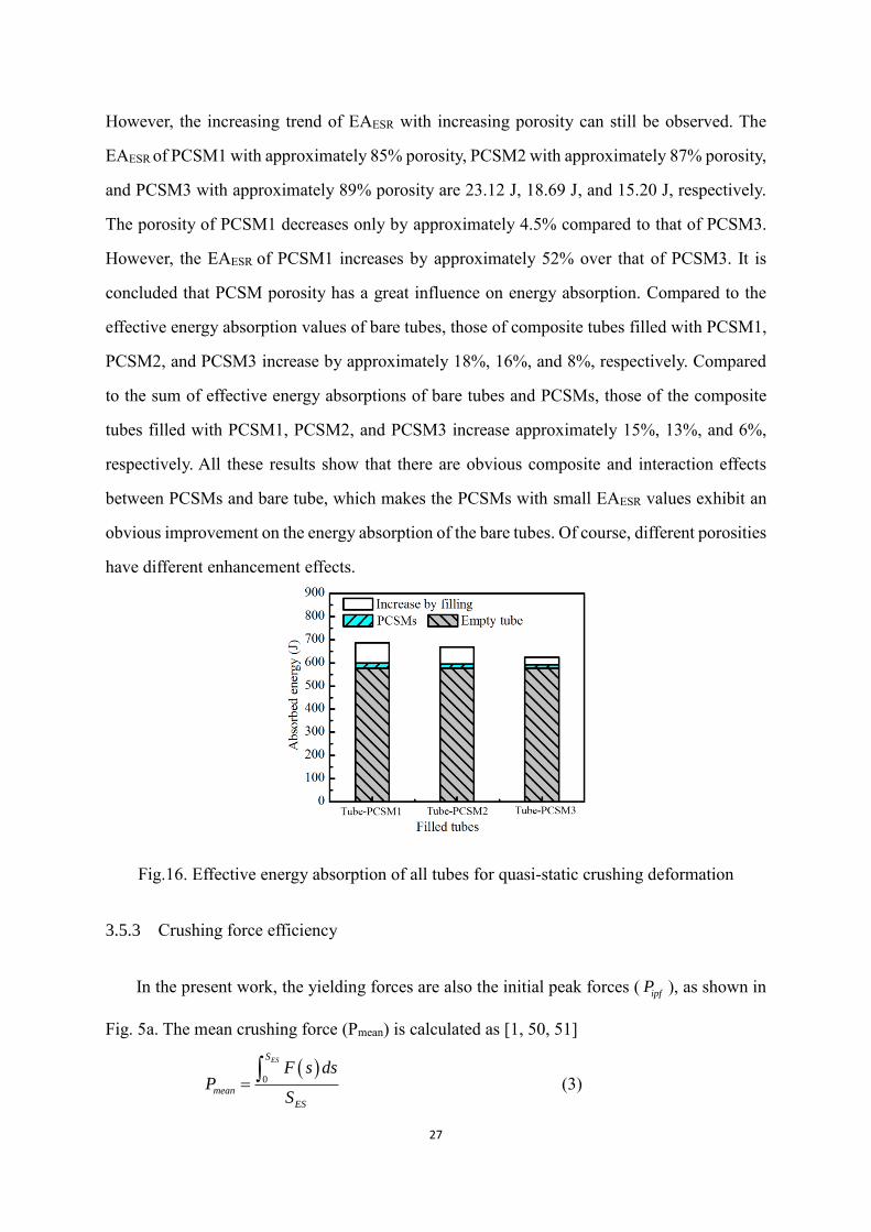
27
However, the increasing trend of EAESR with increasing porosity can still be observed. The
EAESR of PCSM1 with approximately 85% porosity, PCSM2 with approximately 87% porosity,
and PCSM3 with approximately 89% porosity are 23.12 J, 18.69 J, and 15.20 J, respectively.
The porosity of PCSM1 decreases only by approximately 4.5% compared to that of PCSM3.
However, the EAESR of PCSM1 increases by approximately 52% over that of PCSM3. It is
concluded that PCSM porosity has a great influence on energy absorption. Compared to the
effective energy absorption values of bare tubes, those of composite tubes filled with PCSM1,
PCSM2, and PCSM3 increase by approximately 18%, 16%, and 8%, respectively. Compared
to the sum of effective energy absorptions of bare tubes and PCSMs, those of the composite
tubes filled with PCSM1, PCSM2, and PCSM3 increase approximately 15%, 13%, and 6%,
respectively. All these results show that there are obvious composite and interaction effects
between PCSMs and bare tube, which makes the PCSMs with small EAESR values exhibit an
obvious improvement on the energy absorption of the bare tubes. Of course, different porosities
have different enhancement effects.
Fig.16. Effective energy absorption of all tubes for quasi-static crushing deformation
3.5.3 Crushing force efficiency
In the present work, the yielding forces are also the initial peak forces ( ipfP ), as shown in
Fig. 5a. The mean crushing force (Pmean) is calculated as [1, 50, 51]
0
ESS
mean
ES
F s dsP
S
(3)

28
The crushing force efficiency (CFE) is the ratio of the mean crushing force to the initial peak
force [15, 16], as
mean
ipf
PCFE
P (4)
The CFE is a parameter to evaluate the uniformity of the crushing force. A lower CFE
means that the initial impact effect on the structure is too obvious, which is not good for
protective structures. A higher CFE means better structural crashworthiness.
Table 2 summarizes the static crashworthiness parameters of the PCSMs. The initial peak
forces for PCSM1, PCSM2, and PCSM3 are 0.48 kN, 0.38 kN, and 0.32 kN, respectively, and
the mean crushing forces are 0.72 kN, 0.55 kN, and 0.45 kN, respectively. The initial peak
forces and the mean crushing forces of PCSMs are extremely small, less than 0.8 kN. However,
they show very high crushing force efficiencies, i.e., 1.5 (PCSM1), 1.45 (PCSM2), and 1.41
(PCSM3). Although there are small differences, the initial peak forces, mean crushing forces,
and CFEs all decrease with increasing porosity. All the PCSMs have very small initial peak
forces. Further, the mean crushing forces are somewhat higher than their initial peak forces.
This feature is good for structural crashworthiness and shows that there is no initial impact
effect, which indicates that the PCSMs will enter directly into the energy-absorbing platform
stage. The CFE values of PCSMs are higher than those of aluminum foam with high crushing
force efficiency, mainly in the range of 0.8–1.0 [26], and approximately 3 times that of
aluminum honeycomb (0.4–0.5) [26]. The PCSMs may fully utilize their energy absorption
capacity, as do aluminum foam and honeycomb, and satisfy the low peak load requirement for
energy absorbers.
Fig. 17a plots the initial peak force, mean crushing force, and CFE of bare tube and
composite tubes filled with PCSMs for static crushing deformation. Their values are
summarized in Table 2.
The 6063 thin-walled tube presents a large initial peak force (23.57 kN) during the crushing
process; it is much higher than the mean compression force (15.35 kN), as shown in Fig. 4b.
This is a drawback for fully dense thin-walled metal tubes that cannot be ignored. The higher
initial peak force may cause destruction of the object before the tube can play the role of buffer
by absorbing energy. Hence, it is important to reduce or control the initial peak load of the

29
energy absorbing structure. The consistency of the initial peak force and the mean crushing
force (CFE) is highly important for structural crashworthiness. A greater CFE means lower
initial impact, which is beneficial for structural protection.
After matching the thin-walled tubes with the PCSMs, the initial peak forces of filled
composite tubes show a small increase, i.e., from approximately 23.6 kN for bare tube to 24.5
kN for composite tubes. Compared to the initial peak forces of the composite tubes, the mean
crushing forces have a more obvious increase, i.e., from approximately 15.35 kN for bare tube
to approximately 17.92 kN (composite tube with PCSM3) and 19.14 kN (composite tubes with
PCSM2 or PCSM1). The CFE of composite tubes filled with PCSM1, PCSM2, and PCSM3
are 0.78, 0.78, and 0.73, respectively, which represent an increase of 20%, 20% and 12%
compared to that of bare tube (0.65). These results imply that the PCSMs can improve the
crashworthiness of bare tube almost without increasing the initial impact effect. Fig. 12 shows
that the mean crushing force and CFE obviously decrease, and the initial peak force is almost
the same with increasing porosity.
Fig. 17b plots the initial peak force, mean crushing force, and CFE of bare tube and
composite tubes filled with PCSMs for impact deformation. Their values are summarized in
Table 3. The above three parameters of TP23 and PT33 are lower than those of bare tube except
that of TP13. The mean crushing force and CFE of TP13 increase 20% and 16%, respectively,
while the initial peak force only increases by 2.7%. It indicates that the method of filling PCSM
into bare tube is possible to improve the energy absorption ability of thin-walled tube with
almost no increase in the initial peak force.
(a) (b)

30
Fig.17. Comparison on the initial peak force, mean crushing force and CFE of bare and filled
composite tubes: (a) for quasi-static crushing deformation, and (b) for impact deformation
4. Conclusion
In this study, composite tubular structures filled with novel PCSMs were developed, and
their crushing behavior and energy absorption characteristics were captured by quasi-static and
dynamic axial compression experiments. The following conclusions can be drawn within the
limitations of this investigation:
(1) The PCSM preparation method is simple and low-cost because there is no need for a special
mold for cold pressing or special high-cost weaving equipment. The raw material was
continuous single rope, which need not be cut into segments or predeformed. The
macrostructure of lightweight PCSMs were characterized by their inter-crocheted and
multiple interlocked porous structure, rope skeletons, and metallurgical bonds.
(2) The quasi-static load-displacement curves of PCSMs exhibited three typical deformation
stages while their dynamic load-displacement curves go straight into a plastic platform
stage. There were almost no initial impact effects. The porosity of PCSM1 decreased only
by approximately 4.5 percent compared with that of PCSM3. The mean crushing force and
effective energy absorption of PCSM1 for static tests increased by approximately 60% and
52%, respectively compared with those of PCSM3. The mean crushing force and impact
load of the former increased by 6% and decreased by 17% than those of the later. Porosity
has obvious influence on the quasi-static and dynamic behavior and crashworthiness of
PCSMS. The quasi-static and dynamic crushing deformation of PCSM all exhibited the
densification process with coupling structural plastic deformation and rope framework
plastic deformation.
(3) After filling PCSMs into 6063 tubes, the static crushing model of 6063 tube converted from
an asymmetric diamond model to an axisymmetric ring model while its dynamic failed
mode mainly showed petal-like outward fronds with some slivers. Although the static
load-displacement of composite tubes still showed three typical deformation stages, the
load-displacement curves showed different wave positions, widths, and amplitudes. The

31
dynamic load-displacement curves of filled composite tubes are similar to that of 6063 tube.
(4) The static ESRs of the composite tubes (approximately 0.65) were slightly less than that of
bare tube (approximately 0.68) and more than those of the PCSMs (0.58–0.62). The static
values of EAESR, CFE and Pmean of composite tubes are higher approximately 8-18%, 12-
20% and 17-25%, respectively, over that of 6063 tube. However, the initial peak forces
exhibited almost no increase. The dynamic Pmean and CFE of composite tubes filled with
PCSM with 85% porosity increased by 18% and 17% than those of 6063 tube, respectively.
Those parameters of the composite tubes filled with PCSMs with the other two porosities
all decreased. However, the initial peak forces all exhibited almost no increase. The PCSMs
can improve the static crashworthiness of 6063 tube almost without increasing initial
impact effect and doesn’t always play a positive role in dynamic absorption.
(5) The static values of EAESR, Pmean and CFE of composite tubes filled with PCSM with 85%
porosity only increased by approximately 10%, 7% and 7% than those of filled with PCSM
with 89% porosity, respectively. But the dynamic values of Pmean and CFE of the former is
higher 51% and 46% than those of the latter, respectively. The effect of porosity on dynamic
crashworthiness of composite tube is greater obvious than that on quasi-static
crashworthiness of composite tube.
Acknowledgements
The authors gratefully acknowledge the financial support from the National Natural
Science Foundation of China (Grant No. 51705085).
References
[1] Xiang Y.F., Yu T.X., Yang L.M. Comparative analysis of energy absorption capacity of
polygonal tubes, multi-cell tubes and honeycombs by utilizing key performance indicators.
Materials and Design, 2016, 89: 689-696.
[2] Alghamdi A.A.A. Collapsible impact energy absorbers: an overview. Thin-Walled Structure,
2001, 39(2):189-213.
[3] Kavi H., Toksoy A.K., Guden M., Predicting energy absorption in a foam-filled thin-walled
aluminum tube based on experimentally determined strengthening coefficient, Materials
and Design, 2006, 27: 263-269.
[4] Li Y., Lin Z., Jiang A., et al. Use of high strength steel sheet for lightweight and crashworthy

32
car body. Materials and Design, 2003, 24(3):177-182.
[5] Nia A. A., Badnava H., Fallah N.K. An experimental investigation on crack effect on the
mechanical behavior and energy absorption of thin-walled tubes, Materials and Design,
2011, 32, 3594-3607.
[6] Lu G.X., Yu T.X. Energy Absorption of Structures and Materials, CRC Press, Boca Raton,
2003.
[7] Alexander J.M., An approximate analysis of the collapse of thin cylindrical shells under
axial loading, Quarterly Journal of Mechanics and Applied Mathematics, 1960, 13 (1): 10-
15.
[8] Abromowicz W., Jones N., Dynamic progressive buckling of circular and square tubes,
International Journal of Impact Engineering, 1986, 4 (4): 243-270.
[9] Nia A.A., Hamedani J.H. Comparative analysis of energy absorption and deformations of
thin walled tubes with various section geometries. Thin-Walled Structures, 2010, 48: 946-
954.
[10] Fan Z., Lu G., Yu T.X., Liu K., Axial crushing of triangular tubes, International Journal of
Applied Mechanics, 2013,5 (1): 1–21, 1350008.
[11] Nia A.A., Parsapour M. Comparative analysis of energy absorption capacity of simple and
multi-cell thin-walled tubes with triangular, square, hexagonal and octagonal sections.
Thin-Walled Structures, 2014, 74:155-165
[12] Liu W.Y., Lin Z.Q., Wang N.L., et al. Dynamic performances of thin-walled tubes with
star-shaped cross section under axial impact. Thin-Walled Structures, 2016, 100:25-37
[13] Wu F., Xiao X.T., Dong Y., Yang J., Yu Y.Q. Quasi-static axial crush response and energy
absorption of layered composite structure formed from novel crochet-sintered mesh tube
and thin-walled tube. Composite Structures, 2018, 192:592–604.
[14] Wu F., Xiao X.T., Yang J., Gao X.D. Quasi-static axial crushing behaviour and energy
absorption of novel metal rope crochet-sintered mesh tubes.Thin-Walled Structures, 2018,
127: 120-134.
[15] Mahmoodi A., Shojaeefard M.H., Googarchin H.S. Theoretical development and
numerical investigation on energy absorption behavior of tapered multi-cell tubes. Thin-
Walled Structures, 2016, 102: 98-110
[16] Li G.Y., Xu F.X., Sun G.Y., et al. A comparative study on thin-walled structures with f
unctionally graded thickness (FGT) and tapered tubes withstanding oblique impact
loading. International Journal of Impact Engineering, 2015, 77:68-83
[17] Wei Y.P., Yang Z., Yan H., et al. Proactive regulation of axial crushing behavior of thin-
walled circular tube by gradient grooves. International Journal of Mechanical Sciences,
2016, 108-109: 49-60
[18] Taştan A., Acar E.,Güler M.A. Optimum crashworthiness design of tapered thin-walled
tubes with lateral circular cutouts. Tin-Walled Structures, 2016, 107: 543-553
[19] Song J., Chen Y, Lu G.X. Axial crushing of thin-walled structures with origami patterns.
Thin-Walled Structures, 2012, 54: 65-71
[20] Jafarian B., Rezvani M.J., An experimental investigation on energy absorption of thin-
walled bitubal structures by inversion and axial collapse, International Journal of
Mechanical Sciences, 2017, 126: 270-280.
[21] Rezvani M.J., Jahan A. Effect of initiator, design, and material on crashworthiness

33
performance of thin-walled cylindrical tubes: A primary multi-criteria analysis in
lightweight design. Thin-Walled Structures, 2015, 96: 169-182
[22] Sharifi S., Shakeri M., Fakhari H.E., et al. Experimental investigation of bitubal circular
energy absorbers under quasi-static axial load. Thin-Walled Structures, 2015, 89: 42-53
[23] Jusuf A., Dirganatara T., Gunawan L., et al. Crashworthiness analysis of multi-cell
prismatic structures. International Journal of Impact Engineering, 2015, 78: 34-50
[24] Chen W., Wierzbicki T. Relative merits of single-cell, multi-cell and foam-filled thin-
walled structures in energy absorption. Thin-Walled Structure, 2001, 39(4): 287-306
[25] Mahmoodi A., Shojaeefard M.H., Googarchin H.S. Theoretical development and
numerical investigation on energy absorption behavior of tapered multi-cell tubes. Thin-
Walled Structures, 2016, 102: 98-110
[26] Sun G.Y.; Li S.F.; Liu Qiang; Li G.Y.; Li Q. Experimental study on crashworthiness of
empty/aluminum foam/honeycomb–filled CFRP tubes. Composite Structures, 2016, 152:
969-993.
[27] Yin H.F., Xiao Y.Y., Wen G.L., et al. Multiobjective optimization for foam-filled multi-
cell thin-walled structures under lateral impact. Tin-Walled Structures, 2015,94: 1-12
[28] Yin H.F., Wen G.L., Hou S.J., et al. Crushing analysis and multiobjective crashworthiness
optimization of honeycomb-filled single and bitubular polygonal tubes. Materials and
Design, 2011, 32: 4449-4460
[29] Lou X., Xu J.Y., Nie L.G., et al. The mechanical behavior of thin-walled tube filled with
hollow metal spheres. Composite Structures, 2015, 133: 124-130
[30] Kalhor B., Case S.W. The effect of FRP thickness on energy absorption of metal-FRP
square tubes subjected to axial compressive loading. Composite Structures, 2015, 130:
44-50
[31] Seitzberger M, Rammerstorfer FG, Gradinger R, et al. Experimental studies on the quasi-
static axial crushing of steel columns filled with aluminium foam. Int J Solids Struct
2000;37(30):4125–47.
[32] Hanssen AG, Langseth M, Hopperstad OS. Static and dynamic crushing of square
aluminium extrusions with aluminium foam filler. International Journal of Impact
Engineering, 2000, 24(4):347-383.
[33] Song HW, Fan ZJ, Yu G, et al. Partition energy absorption of axially crushed aluminum
foam-filled hat sections. International Journal of Solids and Structures 2005;42(9):2575–
600.
[34] Rajendran R, Sai KP, Chandrasekar B, et al. Impact energy absorption of aluminium foam
fitted AISI 304L stainless steel tube. Mater Des 2009; 30 (5):1777–84.
[35] Santosa S, Wierzbicki T. Crash behavior of box columns filled with aluminum honeycomb
or foam. Comput Struct 1998; 68(4):343–67.
[36] Zarei H, Kröger M. Optimum honeycomb filled crash absorber design. Mater Des
2008;29(1):193–204.
[37] Zhonggang Wang , Shuguang Yao, Zhaijun Lu, David Hui, Luciano Feo. Matching effect
of honeycomb-filled thin-walled square tube—Experiment and simulation. Composite
Structures 157 (2016) 494–505
[38] Qiao J.C., Xi Z.P., Tan H.B., Wang J.Y., Zhu J.L. Influence of porosity on quasi-static
compressive properties of porous metal media fabricated by stainless steel fibers.

34
Materials and Design, 2009, 30: 2737-2740.
[39] Liu P., He G., Wu L.H. Fabrication of sintered steel wire mesh and its compressive
properties. Materials science and engineering A, 2008, 489:21-28.
[40] Wu F., Zhou Z.Y., Yao B.B., Xiao Z.Y. Anisotropic Compressive Properties and Energy
Absorption Efficiency of Porous Twisted Short Fiber Materials. Steel Research
Interactional, 2016, 87(11): 1534-1542.
[41] Xiyue A., Hualin F. Hybrid design and energy absorption of luffa-sponge-like hierarchical
cellular structures. Materials and Design 2016; 106: 247–57.
[42] Neelakantan S., Bosbach W., Woodhouse J., et al. Characterization and deformation
response of orthotropic fibre networks with auxetic out-of plane behaviour. Acta
Materialia, 2014, 66: 326-339.
[43] Tan Q.B., Liu P., Du C.L, Wu L.H., He G. Mechanical behaviors of quasi-ordered
entangled aluminum alloy wire material. Materials Science and Engineering A, 2009, 527:
38–44.
[44] Liu P., Tan Q.B., Wu L.H. Compressive and pseudo-elastic hysteresis behavior of
entangled titanium wire materials. Materials Science and Engineering A, 2010, 527: 3301-
3309.
[34] Kang K.J. Wire-woven cellular metals: The present and future. Progress in Materials
Science, 2015, 69: 213-307
[45] Kang KJ. A wire-woven cellular metal of ultrahigh strength. Acta Mater 2009; 57: 1865–
74.
[47] Fei Wu, Zhaoyao Zhou, Liuyan Duan, Zhiyu Xiao. Processing, Structural Characterization
and Comparative Studies on Uniaxial Tensile Properties of a New Type of Porous Twisted
Wire Material. Materials, 2015, 8(9): 5554-6588
[48] Lee YH, Lee BK, Jeon I, Kang KJ. Wire-woven bulk Kagome truss cores. Acta Mater
2007; 55: 6084–6094.
[49] Zhou W., Tang Y, Liu B., et al. Compressive properties of porous metal fiber sintered sheet
produced by solid-state sintering process. Materials and Design, 2012, 35: 414-418.
[50] Alkbir M.F.M.; Sapuan S.M.; Nuraini A.A.; Ishak M.R. Effect of geometry on
crashworthiness parameters of natural kenaf fibre reinforced composite hexagonal tubes.
Materials and Design, 2014, 60: 85–93.
[51] Ataollahi S.; Taher S.T.; Eshkoor R.A.; Ariffin A.K.; Azhari C.H. Energy absorption and
failure response of silk/epoxy composite square tubes: Experimental. Composites: Part B,
2012, 43: 542-548.