static and dynamic analysis of center cracked finite plate subjected to uniform tensile stress using...
TRANSCRIPT
International Journal of Mechanical Engineering and Technology (IJMET), ISSN 0976 – 6340(Print),
ISSN 0976 – 6359(Online), Volume 6, Issue 1, January (2015), pp. 56-70 © IAEME
56
STATIC AND DYNAMIC ANALYSIS OF CENTER
CRACKED FINITE PLATE SUBJECTED TO UNIFORM
TENSILE STRESS USING FINITE ELEMENT METHOD
Najah R.Mohsin
Southern Technical University, Technical Institute-Nasiriya,
Mechanical Technics Department
ABSTRACT
The study of crack behavior in a plate is a considerable importance in the design to avoid the
failure. This paper deals with investigation of stress intensity factor, Von-Misesstress (ϬVon-mises),
natural frequency, mode shape and the effect of excitation frequency on the finite center cracked
plate subjected to uniform tensile loading depends on the assumptions of Linear Elastic Fracture
Mechanics (LEFM) and plane strain problem. The stress intensity factors mode I (KI) are
numerically calculated by finite element solution using ANSYS (ver. 15) software and theoretically
using standard equations for different crack lengths and plate dimensions. Generally, the results
show that there are no major differences between the two methods. However, the difference between
the two methods occur if we take the plate length parameter in considerate. Furthermore, ϬVon-mises at
crack tip region, 10th natural frequencies and the effect of excitation frequency on the crack tip
stresses are studied for three different materials.
Keywords: Crack Tip, Stress Intensity Factor, Natural Frequency, Finite Element Method (FEM),
Harmonic Analysis, Linear Elastic Fracture Mechanics (LEFM).
1- INTRODUCTION
In general, a fracture is defined as the local separation of an object or material into two or
more pieces under the action of stress. Usually, the fracture of a plate occurs due to the development
of certain displacement discontinuity surfaces within the plate.
Recent development in engineering structures shows that fracture can be caused by small
cracks in the body of structures despite the authenticity of elasticity theory and strength of materials.
INTERNATIONAL JOURNAL OF MECHANICAL ENGINEERING AND
TECHNOLOGY (IJMET)
ISSN 0976 – 6340 (Print)
ISSN 0976 – 6359 (Online)
Volume 6, Issue 1, January (2015), pp. 56-70
© IAEME: www.iaeme.com/IJMET.asp
Journal Impact Factor (2014): 7.5377 (Calculated by GISI)
www.jifactor.com
IJMET
© I A E M E
International Journal of Mechanical Engineering and Technology (IJMET), ISSN 0976 – 6340(Print),
ISSN 0976 – 6359(Online), Volume 6, Issue 1, January (2015), pp. 56-70 © IAEME
57
As a result, fracture mechanics filed which is concerned with the propagation of cracks in materials
has developed to study more about this subject, Ali and et al. [1].
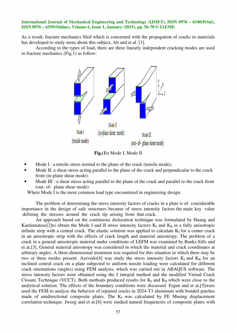
According to the types of load, there are three linearly independent cracking modes are used
in fracture mechanics (Fig.1) as follow:
Fig.(1): Mode I, Mode II
• Mode I : a tensile stress normal to the plane of the crack (tensile mode),
• Mode II: a shear stress acting parallel to the plane of the crack and perpendicular to the crack
front (in-plane shear mode).
• Mode III : a shear stress acting parallel to the plane of the crack and parallel to the crack front
(out- of- plane shear mode)
Where Mode I is the most common load type encountered in engineering design.
The problem of determining the stress intensity factors of cracks in a plate is of considerable
importance in the design of safe structures because of stress intensity factors the main key value
defining the stresses around the crack tip arising from that crack.
An approach based on the continuous dislocation technique was formulated by Huang and
Kardomateas[2]to obtain the Mode I and II stress intensity factors KI and KII in a fully anisotropic
infinite strip with a central crack. The elastic solution was applied to calculate KI for a center crack
in an anisotropic strip with the effects of crack length and material anisotropy. The problem of a
crack in a general anisotropic material under conditions of LEFM was examined by Banks-Sills and
et at.[3]. General material anisotropy was considered in which the material and crack coordinates at
arbitrary angles. A three-dimensional treatment was required for this situation in which there may be
two or three modes present. Azevedo[4] was study the stress intensity factors KI and KII for an
inclined central crack on a plate subjected to uniform tensile loading were calculated for different
crack orientations (angles) using FEM analysis, which was carried out in ABAQUS software. The
stress intensity factors were obtained using the J integral method and the modified Virtual Crack
Closure Technique (VCCT). Both methods produced results for KI and KII which were close to the
analytical solution. The effects of the boundary conditions were discussed. Ergun and et at.[5]were
used the FEM to analyze the behavior of repaired cracks in 2024-T3 aluminum with bonded patches
made of unidirectional composite plates. The KI was calculated by FE Musing displacement
correlation technique. Jweeg and et at.[6] were studied natural frequencies of composite plates with

International Journal of Mechanical Engineering and Technology (IJMET), ISSN 0976 – 6340(Print),
ISSN 0976 – 6359(Online), Volume 6, Issue 1, January (2015), pp. 56-70 © IAEME
58
the effect of crack orientation, crack position, crack size and based on the shape of the fibers . They
made a comparison between the analytical results and the results get by finite element solution using
ANSYS (ver.14) software. Bhagat and et at.[7] were studied a finite rectangular plate of unit
thickness with two inclined cracks (parallel and non-parallel) under biaxial mixed mode condition
were modeled using FEM. The FEM was used for determination of stress intensity factor by ANSYS
software. Effects of crack inclination angle on stress intensity factor for two parallel and non-parallel
cracks are investigated. The significant effects of different crack inclination parameters on stress
intensity factor were seen for lower and upper crack in two inclined crack. Al-Ansari [8] was a
comparison between six models, calculating KI for central cracked plate with uniform tensile stress,
was made in order to select the suitable model. These models were three theoretical models and three
numerical models. The three numerical models are half ANSYS model, quarter ANSYS model and
weight function model. Crack geometry, crack length, plate length and the applied stresses are the
parameters that used to compare between the models. He concludes that the three theoretical models
can recognize the effect of the width of the plate, the crack length and applied stress but they failed
to recognize the effect of the length of the plate. Ali and et at.[1] were attempts to analyze the stress
intensity factor in various edge cracks along the length of a finite plate which was under a uniform
tension. FEM was utilized for the analysis. In addition, Neural Network Method (NNM) was used to
predict the correlation of stress intensity factor and the position of edge crack along the length of a
finite plate.
For certain cracked configurations subjected to external forces, it is possible to derive closed-
form expressions for the stresses in the body, assuming isotropic linear elastic material behavior. If
we define a polar coordinate axis with the origin at the crack tip Fig.(2), it can be shown that the
stress field in any linear elastic cracked body is given by Anderson[9]
σ�� = � �√� f���θ� + ∑ A�.∞��� r�� . g������θ�, …………….(1)
where Ϭij stress tensor, r and θ are as defined in Fig.(2) , kconstant, fij dimensionless function
of θ in the leading term, Am is the amplitude for the higher-order terms and gij(m)
is a dimensionless
function of θ for the mth
term.
Fig.(2): Definition of the coordinate Mode III crack loading axis ahead of a crack tip

International Journal of Mechanical Engineering and Technology (IJMET), ISSN 0976 – 6340(Print),
ISSN 0976 – 6359(Online), Volume 6, Issue 1, January (2015), pp. 56-70 © IAEME
59
The higher-order terms depend on geometry, but the solution for any given configuration
contains a leading term that is proportional to 1/√r.As r → 0, the leading term approaches infinity,
but the other terms remain finite or approach zero. Thus, stress near the crack tip varies with 1/√r,
regardless of the configuration of the cracked body. It can also be shown that displacement near the
crack tip varies with √r. Eq.(1) describes a stress singularity, since stress is asymptotic to r =0.
Most cracks are long and sharp tips. These can be of atomic dimensions in brittle materials.
In 1938, Westergaard solved the stress field for an infinitely sharp crack in an infinite plate. The
elastic stresses were given by the equations, Rae [10].
σ�� = ��√�π� cos �θ� �1 − sin �θ� sin �#θ� $ ……………..(2)
σ%% = ��√�π� cos �θ� �1 + sin �θ� sin �#θ� $ ……………..(3)
σ�% = ��√�π� cos �θ� sin �θ� cos �#θ� ………………..…..(4)
Similar expressions for displacements u
u� = ���µ' �
�π cos �θ� �k − 1 + 2sin� �θ�$ …….……..(5)
u% = ���µ' �
�π sin �θ� �k + 1 − 2cos� �θ�$, …………..(6)
Where µ denotes the shear modulus, k the small difference in formulas for plane stress and plane
strain which is equal to
k = * #+,-., …………….�PlaneStress�3 − 4v …………….�PlaneStrain�9….… (7)
Based on the above equations, we show that, the KI defines the amplitude of the crack-tip
singularity. That is, stresses near the crack tip increase in proportion to KI. Moreover, the stress
intensity factor completely defines the crack tip conditions, if KIis known, it is possible to solve for
all components of stress, strain, and displacement as a function of r and θ. This single-parameter
description of crack tip conditions turns out to be one of the most important concepts in fracture
mechanics, Anderson [9].
Table (1): Mechanical properties used for selected material, Kulkani [12]
Material type Modulus of elasticity
(Mpa) Poisons ratio
density
(Kg/m3
)
Aluminum(alloy) 0.71e5 0.334 2730
Carbon Steel 2.02 e5 0.292 7820
Nickel Silver 1.275 e5 0.322 8690

International Journal of Mechanical Engineering and Technology (IJMET), ISSN 0976 – 6340(Print),
ISSN 0976 – 6359(Online), Volume 6, Issue 1, January (2015), pp. 56-70 © IAEME
60
2- MATERIALS AND METHODS
2.1- Based on the assumptions of LEFM and plane strain problem, KI to a center cracked plate
under static load were numerically calculated using FEM for three materials Carbon Steel ,
Aluminum(alloy) and Nickel Silver materials are shown in Table (1)and theoretically using
the two standard equations as follows
a) From Ergun and et at.[5] and Rae[10]
K; = σ√π ∗ a =Sec �π∗>�?- �@ A B1 − 0.025 �>?
� + 0.06 �>?FG…..………. (8)
b) From Al-Ansari[8]
K; = σ√π ∗ a B1 + 0.128 �>? − 0.288 �>?� + 1.523 �>?
FG ………….. (9)
2.2- For practical considerations, any kinds of stress, strains and deformations in single parts or
assemblies can be better approximated using FEM. FEM is a numerical technique in which
the governing equations are represented in matrix form, which is to be solved by computer
software. The solution region is represented as an assemblage of small sub-regions called
finite element. The element is the basic building unit with a predetermined number of degrees
of freedom (d.o.f) and can take various forms, e.g. beam, plate, shell or solid elements. The
selection of the best element depends on the type of problem, geometry of boundaries,
boundary conditions, accuracy required, size of the available computer and the maximum
allowable computing cost.
The main purpose of this paper is to observe the behave or of finite plate with a central crack
under the effect of some parameters such as a ratio of crack length to width plate, ratio of width to
length plate, applied stress for different materials by calculating the stress intensity factors KI and
ϬVon-mises to the crack tip. Natural frequencies, mode shapes and also the effect of excitation
frequencies are studied in this paper. Quarter model is selected to represent the finite plate with
center crack in the FEM software (ANSYS ver.15) because the geometry and load applied for
specimen is symmetry (Fig.3).
To compute the required results in a faster and accuracy way, programs are written with
APDL (Ansys Parameter Design Language).The first step of these softwares is to discretize the
structure into finite elements connected at nodes. It is necessary to discretize the plate structure into a
sufficient number of elements in order to obtain a reasonable accuracy, on the other side, the more
elements that are used, the more costly it will be. In this paper, PLANE183 is used as a discretization
element.

International Journal of Mechanical Engineering and Technology (IJMET), I
ISSN 0976 – 6359(Online), Volume 6, Issue 1, January (2015), pp.
Fig. (3): Center cracked plate
Fig. (4): Geometry, node locations and
3- PLANE183 ELEMENT DESCRIPTI
PLANE183 is an isoperimetric
displacement behavior element which is better suited to
be used as a plane element (plane stress, plane strain and general
axisymmetric element. It has two degree of freedom (translation in X and Y directions) at each
Fig.(4)shows the geometry, node
model used in this paper with elements, nodes,
in Fig.(5).
International Journal of Mechanical Engineering and Technology (IJMET), ISSN 0976
6359(Online), Volume 6, Issue 1, January (2015), pp. 56-70 © IAEME
61
Center cracked plate specimen with dimensions
Geometry, node locations and the co-ordinate system for PLANE183 Element,
ANSYS help [11]
PLANE183 ELEMENT DESCRIPTION
isoperimetric eight or six nodes(I,J,K,L,M,N,O,P)
displacement behavior element which is better suited to modeling irregular meshes .The element may
be used as a plane element (plane stress, plane strain and generalized plane strain) or as an
two degree of freedom (translation in X and Y directions) at each
locations and the co-ordinate system for PLANE183
ements, nodes, boundary conditions and mesh generation
SSN 0976 – 6340(Print),
© IAEME
with dimensions
ordinate system for PLANE183 Element,
(I,J,K,L,M,N,O,P) quadratic or triangle
modeling irregular meshes .The element may
ized plane strain) or as an
two degree of freedom (translation in X and Y directions) at each node.
PLANE183 element. The
boundary conditions and mesh generation are shown

International Journal of Mechanical Engineering and Technology (IJMET), ISSN 0976 – 6340(Print),
ISSN 0976 – 6359(Online), Volume 6, Issue 1, January (2015), pp. 56-70 © IAEME
62
Fig. (5): Mesh generation for quarter model with 556 elements, 1709 nodes and boundary conditions
4- APDL PROGRAM
In the written APDL program, there are four important processors are used
4.1- Preprocessor (/PREP7):This command contains what you need to use to build a model
such as define element types, real constant ,material properties ,create model geometry
and mesh the object created.
4.2- Solution Processor (/SOLU):This command allows to apply boundary conditions, loads
and create the concentration key point (crack tip) using the(KSCON)command .This
processor contents different analysis such as:
4.2.1- Static analysis (ANTYPE, STATIC): To determine the structure analysis under
static loads.
4.2.2- Mode Analysis (ANTYPE, MODAL): It is used to determine the magnitude of
natural frequencies and mode shapes for the structure.
4.2.3- Harmonic Analysis (ANTYPE, HARMIC): Harmonic response analysis is a
technique used to determine the steady-state response of a linear structure to loads
that vary sinusoidally (harmonically) with time.
4.3- Postprocessor (/Post1): This command used to display the results of stress intensity factor
in lists and display ϬVon-mises in lists, plots or curves.
4.4- The Time-History Postprocessor (/POST26): This command is used to evaluate solution
results at specific points in the model as a function of time, frequency, or some other
change in the analysis parameters that can be related to time. Fig.(6) shows the APDL
flow chart.
Carbon Steel, Aluminum (alloy) and Nickel Silver materials (Table 1) are studied in this paper
to calculate KI, ϬVon-mises with range of a/b at b=0.3 m, range of b/hat b=0.3m, range of b/h at
h=0.3m, range of applied stress, first 10th
natural frequencies, mode shapes and range of excitation
frequency, where a, b and h are defined in Fig.(3).

International Journal of Mechanical Engineering and Technology (IJMET), ISSN 0976 – 6340(Print),
ISSN 0976 – 6359(Online), Volume 6, Issue 1, January (2015), pp. 56-70 © IAEME
63
Fig.(6): Flow chart of APDL program
Define element type with plane strain option
Great the model area
Great crack point using KSCON command
Discretize lines into suitable division number
Define crack face path
Model analysis
Define material properties
Calculate KI&ϬVon-misesusing
KCALC& PRNSOL command
General Postproc
Select freq. range
and no. of substeps
Select no. of
mode to extract
Define keypoints and lines for model geometry with center crack
Change active CS to
specified CS
Solve
Calculate natural
frequency and
plot mode shape
Apply boundary conditions (displacement & applied stresses)
Time History Variable
Define local crack tip CS
Mesh the model
Harmonic analysis Static analysis
Solution
Solve
General Postproc
Solve
Plot ϬVon-Mises
with the reang of
Exit
Start
International Journal of Mechanical Engineering and Technology (IJMET), ISSN 0976 – 6340(Print),
ISSN 0976 – 6359(Online), Volume 6, Issue 1, January (2015), pp. 56-70 © IAEME
64
5- RESULTS AND DISCUSSIONS
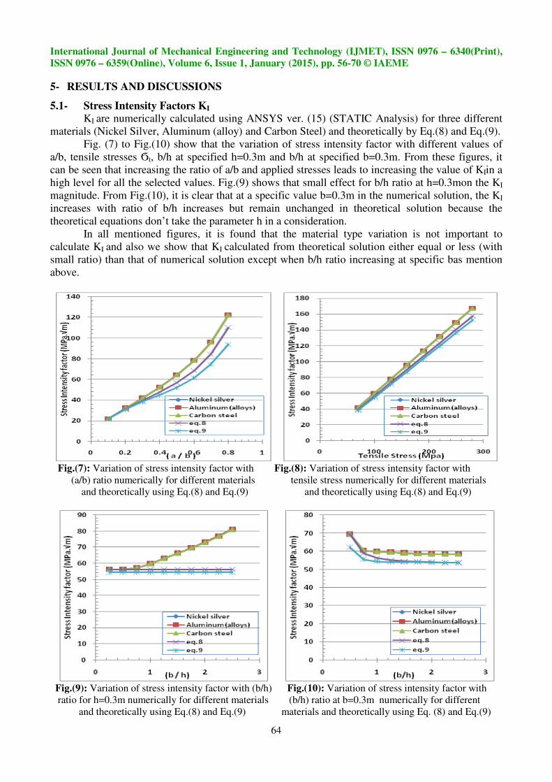
5.1- Stress Intensity Factors KI
KI are numerically calculated using ANSYS ver. (15) (STATIC Analysis) for three different
materials (Nickel Silver, Aluminum (alloy) and Carbon Steel) and theoretically by Eq.(8) and Eq.(9).
Fig. (7) to Fig.(10) show that the variation of stress intensity factor with different values of
a/b, tensile stresses Ϭt, b/h at specified h=0.3m and b/h at specified b=0.3m. From these figures, it
can be seen that increasing the ratio of a/b and applied stresses leads to increasing the value of KIin a
high level for all the selected values. Fig.(9) shows that small effect for b/h ratio at h=0.3mon the KI
magnitude. From Fig.(10), it is clear that at a specific value b=0.3m in the numerical solution, the KI
increases with ratio of b/h increases but remain unchanged in theoretical solution because the
theoretical equations don’t take the parameter h in a consideration.
In all mentioned figures, it is found that the material type variation is not important to
calculate KI and also we show that KI calculated from theoretical solution either equal or less (with
small ratio) than that of numerical solution except when b/h ratio increasing at specific bas mention
above.
Fig.(7): Variation of stress intensity factor with Fig.(8): Variation of stress intensity factor with
(a/b) ratio numerically for different materials tensile stress numerically for different materials and theoretically using Eq.(8) and Eq.(9) and theoretically using Eq.(8) and Eq.(9)
Fig.(9): Variation of stress intensity factor with (b/h) Fig.(10): Variation of stress intensity factor with
ratio for h=0.3m numerically for different materials (b/h) ratio at b=0.3m numerically for different
and theoretically using Eq.(8) and Eq.(9) materials and theoretically using Eq. (8) and Eq.(9)
International Journal of Mechanical Engineering and Technology (IJMET), ISSN 0976 – 6340(Print),
ISSN 0976 – 6359(Online), Volume 6, Issue 1, January (2015), pp. 56-70 © IAEME
65
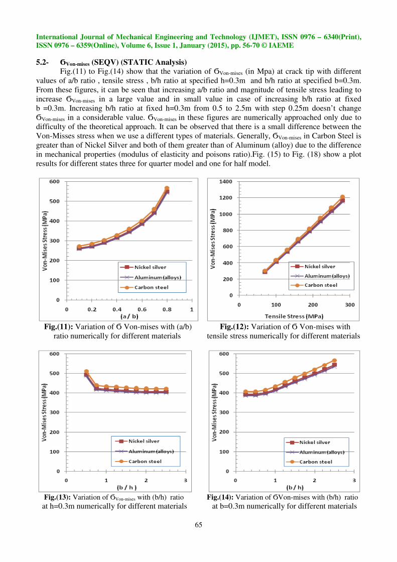
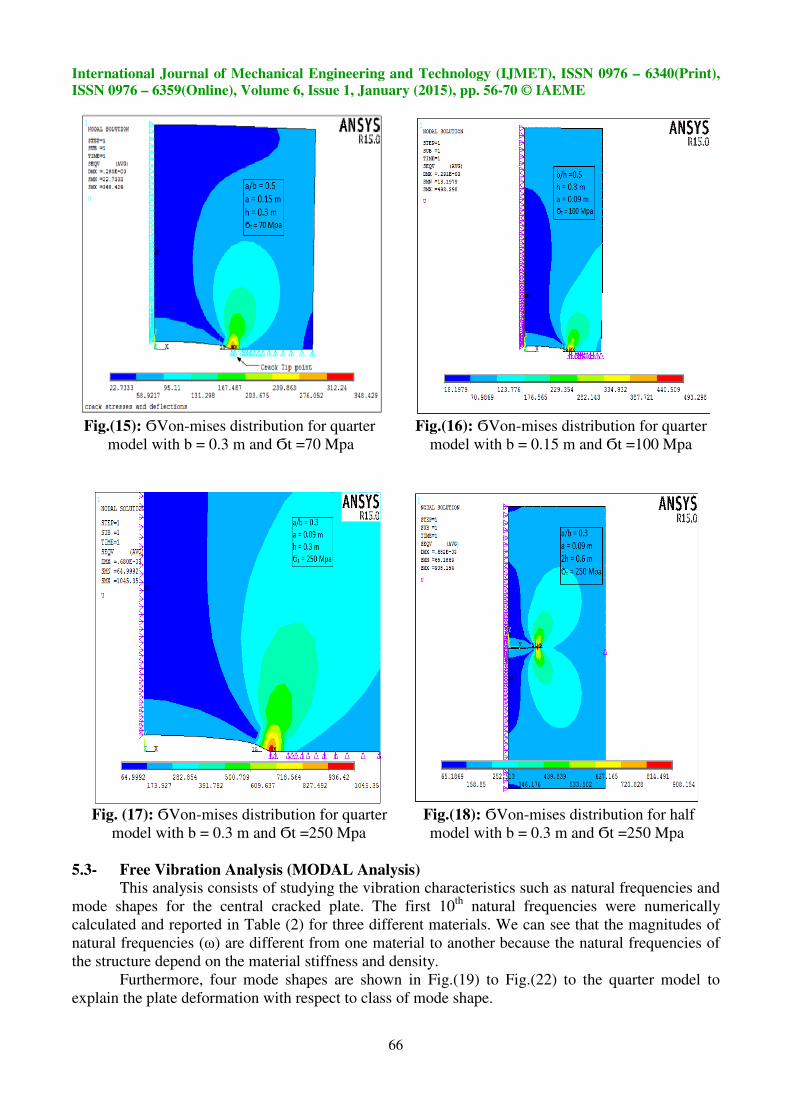
5.2- ϬVon-mises (SEQV) (STATIC Analysis)
Fig.(11) to Fig.(14) show that the variation of ϬVon-mises (in Mpa) at crack tip with different
values of a/b ratio , tensile stress , b/h ratio at specified h=0.3m and b/h ratio at specified b=0.3m.
From these figures, it can be seen that increasing a/b ratio and magnitude of tensile stress leading to
increase ϬVon-mises in a large value and in small value in case of increasing b/h ratio at fixed
b =0.3m. Increasing b/h ratio at fixed h=0.3m from 0.5 to 2.5m with step 0.25m doesn’t change
ϬVon-mises in a considerable value. ϬVon-mises in these figures are numerically approached only due to
difficulty of the theoretical approach. It can be observed that there is a small difference between the
Von-Misses stress when we use a different types of materials. Generally, ϬVon-mises in Carbon Steel is
greater than of Nickel Silver and both of them greater than of Aluminum (alloy) due to the difference
in mechanical properties (modulus of elasticity and poisons ratio).Fig. (15) to Fig. (18) show a plot
results for different states three for quarter model and one for half model.
Fig.(11): Variation of Ϭ Von-mises with (a/b) Fig.(12): Variation of Ϭ Von-mises with
ratio numerically for different materials tensile stress numerically for different materials
Fig.(13): Variation of ϬVon-mises with (b/h) ratio Fig.(14): Variation of ϬVon-mises with (b/h) ratio at h=0.3m numerically for different materials at b=0.3m numerically for different materials
International Journal of Mechanical Engineering and Technology (IJMET), ISSN 0976 – 6340(Print),
ISSN 0976 – 6359(Online), Volume 6, Issue 1, January (2015), pp. 56-70 © IAEME
66
Fig.(15): ϬVon-mises distribution for quarter Fig.(16): ϬVon-mises distribution for quarter
model with b = 0.3 m and Ϭt =70 Mpa model with b = 0.15 m and Ϭt =100 Mpa
Fig. (17): ϬVon-mises distribution for quarter Fig.(18): ϬVon-mises distribution for half
model with b = 0.3 m and Ϭt =250 Mpa model with b = 0.3 m and Ϭt =250 Mpa
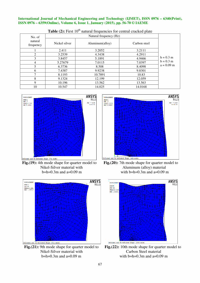
5.3- Free Vibration Analysis (MODAL Analysis)
This analysis consists of studying the vibration characteristics such as natural frequencies and
mode shapes for the central cracked plate. The first 10th
natural frequencies were numerically
calculated and reported in Table (2) for three different materials. We can see that the magnitudes of
natural frequencies (ω) are different from one material to another because the natural frequencies of
the structure depend on the material stiffness and density.
Furthermore, four mode shapes are shown in Fig.(19) to Fig.(22) to the quarter model to
explain the plate deformation with respect to class of mode shape.
International Journal of Mechanical Engineering and Technology (IJMET), ISSN 0976 – 6340(Print),
ISSN 0976 – 6359(Online), Volume 6, Issue 1, January (2015), pp. 56-70 © IAEME
67
Table (2): First 10th
natural frequencies for central cracked plate
No. of
natural
frequency
Natural frequency (Hz)
h = 0.3 m
b = 0.3 m
a = 0.09 m
Nickel silver Aluminum(alloy) Carbon steel
1 2.411 3.2052 3.2111
2 3.2539 4.3438 4.2911
3 3.8457 5.1891 4.9466
4 5.27679 7.0115 7.0397
5 6.3736 8.508 8.4098
6 7.4387 9.9238 9.8301
7 8.1193 10.7891 10.83
8 9.1324 12.199 12.059
9 10.196 13.562 13.563
10 10.547 14.025 14.0168
Fig.(19): 4th mode shape for quarter model to Fig.(20): 7th mode shape for quarter model to
Nikel-Silver material with Aluminum (alloy) material
b=h=0.3m and a=0.09 m with b=h=0.3m and a=0.09 m
Fig.(21): 9th mode shape for quarter model to Fig.(22): 10th mode shape for quarter model to
Nikel-Silver material with Carbon Steel material
b=h=0.3m and a=0.09 m with b=h=0.3m and a=0.09 m
International Journal of Mechanical Engineering and Technology (IJMET), ISSN 0976 – 6340(Print),
ISSN 0976 – 6359(Online), Volume 6, Issue 1, January (2015), pp. 56-70 © IAEME
68
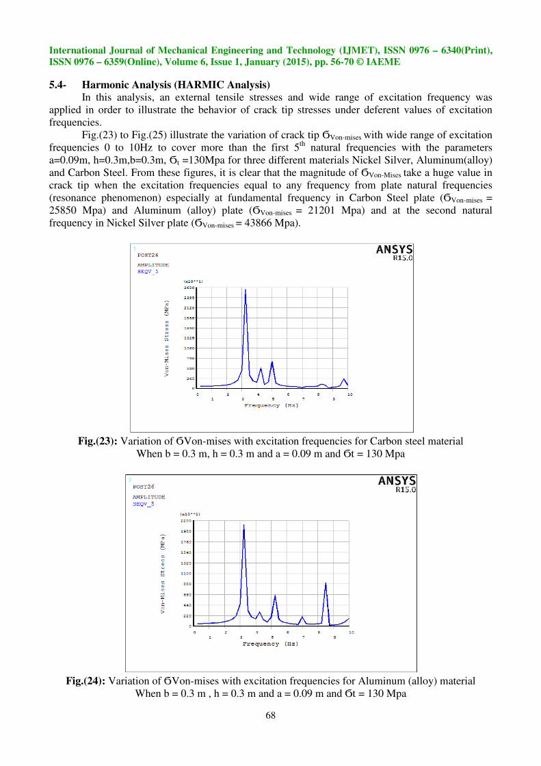
5.4- Harmonic Analysis (HARMIC Analysis)
In this analysis, an external tensile stresses and wide range of excitation frequency was
applied in order to illustrate the behavior of crack tip stresses under deferent values of excitation
frequencies.
Fig.(23) to Fig.(25) illustrate the variation of crack tip ϬVon-mises with wide range of excitation
frequencies 0 to 10Hz to cover more than the first 5th
natural frequencies with the parameters
a=0.09m, h=0.3m,b=0.3m, Ϭt =130Mpa for three different materials Nickel Silver, Aluminum(alloy)
and Carbon Steel. From these figures, it is clear that the magnitude of ϬVon-Mises take a huge value in
crack tip when the excitation frequencies equal to any frequency from plate natural frequencies
(resonance phenomenon) especially at fundamental frequency in Carbon Steel plate (ϬVon-mises =
25850 Mpa) and Aluminum (alloy) plate (ϬVon-mises = 21201 Mpa) and at the second natural
frequency in Nickel Silver plate (ϬVon-mises = 43866 Mpa).
Fig.(23): Variation of ϬVon-mises with excitation frequencies for Carbon steel material
When b = 0.3 m, h = 0.3 m and a = 0.09 m and Ϭt = 130 Mpa
Fig.(24): Variation of ϬVon-mises with excitation frequencies for Aluminum (alloy) material
When b = 0.3 m , h = 0.3 m and a = 0.09 m and Ϭt = 130 Mpa

International Journal of Mechanical Engineering and Technology (IJMET), ISSN 0976 – 6340(Print),
ISSN 0976 – 6359(Online), Volume 6, Issue 1, January (2015), pp. 56-70 © IAEME
69
Fig.(25): Variation of Ϭ Von-mises with excitation frequencies for Nickle-Silver material
When b = 0.3 m, h = 0.3 m and a = 0.09 m and Ϭt = 130 Mpa
6- CONCLUSIONS
The main conclusions of this work are reported below
6.1- Increasing the crack length and applied stresses lead to increasing the value of KI. In the other
hand, KIvalue change with the change of plate length in the numerical solution but remains
constant in theoretical solution as the theoretical equations don’t take this parameter in a
consideration.
6.2- There is no sensitive effect of the material type on the value of KI.
6.3- The first 10th
natural frequencies for three material types are shown to be different for the
same plate dimensions and boundary conditions because the natural frequency depends on the
stiffness and density of the material.
6.4- ϬVon-mises value takes a huge value at crack tip region when the excitation frequency equals to
any frequency from plate natural frequencies (resonance phenomenon) especially at
fundamental frequency in Carbon Steel and Aluminum (alloy) plate) and at the second natural
frequency in Nickel Silver plate .
7- REFERENCES
[1] Z. Ali, K. Esfahan, S. Meysam, A. Iman, B. Aydin and B. Yashar, “FEM Analysis of
Stress Intensity Factor in Different Edge Crack Positions, and Predicting their Correlation
using Neural Network Method”, Research Journal of Recent Sciences, Vol.3(2), p.p. 69-
73, 2014.
[2] H. Huang and G.A. Kardomateas, “Stress intensity factors for a mixed mode center crack
in an anisotropic strip”, International Journal of Fracture, Vol. 108, p.p. 367–381, 2001.
[3] L. Banks-Sills, P.A. Wawrzynek, B. Carter, A.R. Ingraffea and I. Hershkovitz, “Methods
for calculating stress intensity factors in anisotropic materials: Part II—Arbitrary
geometry”, Engineering Fracture Mechanics, Vol.74, p.p. 1293-1307, 2007.
International Journal of Mechanical Engineering and Technology (IJMET), ISSN 0976 – 6340(Print),
ISSN 0976 – 6359(Online), Volume 6, Issue 1, January (2015), pp. 56-70 © IAEME
70
[4] P.C.M. Azevedo, “Stress intensity factors determination for an inclined
central crack on a plate subjected to uniform tensile loading using FE
analysis”, http://paginas.fe.up.pt/~em02115/index_files/r1.pdf, 2008.
[5] E. Ergun, S. Tasgetiren and M. Topcu, “ Stress intensity factor estimation of repaired
aluminum plate with bonded composite patch by combined genetic algorithms and FEM
under temperature effects”, Indian Journal of Engineering & Materials Sciences, Vol. 19,
P.P. 17-23, 2012.
[6] M. J. Jweeg, A, S. Hammood and M. Al-Waily, “Analytical Solution to Oblique Crack
Effect for Difference Composite Material Plates”, ARPN Journal of Science and
Technology, Vol. 2, NO 8, p.p. 697-716, 2012.
[7] R. K. Bhagat, V. K. Singh, P. C. Gope and A.K. Chaudhary, “Evaluation of stress intensity
factor of multiple inclined cracks under biaxial loading “, Fratturaed Integrità Strutturale ,
Vol. 22, p.p. 5-11, 2012.
[8] Dr. L. S. Al-Ansari, “Calculating Stress Intensity Factor (Mode I) for Plate with Central
Crack: Review and Comparison between Several Techniques of Calculations”, Asian
Transactions on Engineering, Vol. 2, p.p. 44-56,2012.
[9] T.L.Anderson, “Fracture Mechanics Fundamentals and Applications”, Third Edition,
Taylor &Francis Group, CRC Press, 2005.
[10] Dr. C.Rae, “ Fracture and Fatigue”, Natural Sciences Tripos Part II, Material Science,
Easter Term 2013-14, Department of Materials Science and Metallurgy, C15, University
of Cambridge, 2014.
[11] ANSYS help.
[12] S.G.Kulkani, “Machine Design”, Sixth reprint, McGraw-Hill companies, 2012.