static and buckling analysis of plates using spline finite ... · static and buckling analysis of...
TRANSCRIPT

Static and buckling analysis of plates using spline finite strip method
with modified amending schemes
*Ajeesh S S1) and S Arul Jayachandran2)
1), 2) Department of Civil Engineering, Indian Institute of Technology, Madras, Chennai, 600036, India
ABSTRACT
Spline finite strip method (SFSM) replaces the trigonometric function in finite strip method more often with piecewise interpolating cubic basic (B3) splines function in the longitudinal direction and beam shape functions in the transverse direction. The SFSM overcomes the short comings of classical finite strip method in handling of continuous spans and mixed boundary conditions in the longitudinal direction. SFSM can also represent abrupt change in bending moment at interior supports and points of concentrated loads and irregularity in plate geometry. In SFSM various geometric boundary conditions are imposed by amending the boundary splines. Some researchers inadvertently use boundary amendment schemes which may destroy the symmetricity of resulting stiffness matrices. The contribution of the present paper is in proposing suitable boundary spline amendment scheme which retains the symmetricity of stiffness matrix. A spline finite strip method program has been developed for static and buckling analysis of plates and the proposed amendment schemes are demonstrated to be correct for various loading and boundary conditions. The numerical results of the present formulation agree with standard bench mark problems. 1. INTRODUCTION The implementation of classical finite strip method (CFSM) for the analysis of thin plated structures provide economy in terms of nodal degree of freedom and computation time compared to finite element method. The method is a combination of Ritz-Galerkin approach and finite element concept and chooses beam vibration function in one direction and polynomial interpolation function in the other direction. The main disadvantage of this method is the infinite continuity of the beam vibration function, which makes it difficult in implementing complex boundary conditions and discontinuity. The continuity and discontinuity requirements during the analysis can be achieved by replacing the beam vibration function using spline function. The spline function is capable of representing desired degree of continuity and discontinuity as well as
1)
PhD Scholar 2)
Associate Professor

capable of adopting prescribed boundary and interior conditions. The spline finite strip method (SFSM) was introduced in structural analysis by Fan (1982). Lau (1986) introduced a method of buckling analysis of thin-walled structures subjected to longitudinal compression and bending, transverse compression as well as shear using spline finite strip method by incorporating various boundary conditions. A method of inelastic buckling analysis of thin-walled structural members and plates based on spline finite strip method was introduced taking the non-linear material stress-strain properties, strain hardening and residual stresses into account (Lau 1989). Hancock (1990) performed buckling and nonlinear analysis of thin-walled members undergoing local, distortional and overall buckling incorporating full nonlinear response with post-local buckling and plasticity using spline finite strip method. A cubic B-spline finite strip method was developed to analyze thin plates in bending allowing local refinement near patch and concentrated loads (Gutkowski 1991). A nonlinear elastic analysis based on spline finite strip method has been developed by Kwon (1991) for studying the post-buckling behaviour of thin-walled sections. The method can handle local, distortional and overall buckling modes in the post-buckling range and the interaction between them. It allows for geometric imperfections, arbitrary loading and non-simple boundary conditions. The two incremental-iterative strategies adopted in the nonlinear analysis are the arc-length method and the improved iteration method based on displacement control. Yao (2011(a), 2011(b)) presented the analytical developments and numerical implementations of isoparametric spline finite strip method to the material inelastic and geometric nonlinear analysis of perforated thin-walled steel structures. The numerical implementation including nonlinear solution techniques, inelastic material models, selective reduced integration strategies, convergence criteria, and solution procedures were also reported. Analysis of plain channel section under shear was done by Pham (2013) using spline finite strip method. The present study aims at linear elastic and buckling analysis of plates using spline finite strip method with modified boundary spline amendment schemes. The analysis of plates under various loading and boundary condition are compared with classical solutions. 2. BASICS OF SPLINE FINITE STRIP METHOD In spline finite strip method, the thin walled prismatic member is discretized by n nodal lines in transverse direction (x axis) and m sections along longitudinal direction (y axis). Basic cubic spline (B3) having five section is adopted in the present study. A local B3 spline is a piecewise cubic polynomial which is twice differentiable. Two additional section knots are defined one on either side of each nodal line to completely define the spline function over the length of the strip. A local B3 spline and spline series is shown in Fig. 1.

Fig. 1 (a) Local B3 spline (b) B3 spline series
Each section knot has four degree of freedom, two out of plane deformations (w, θxz) and two in-plane displacements (u, v). In the present study, only the flexural displacements are considered. The displacement function of the strip is expressed as the product of spline function in longitudinal direction and displacement along transverse direction. A standard B3 spline function is defined by
( )
{
( )
( ) ( ) ( )
( ) ( ) ( )
( )
}
(1)
Spline amendment scheme has to be implemented at ends for various boundary conditions. Two additional section knots are introduced one at either end of the plate strip to completely define the amendment scheme. Several researchers have used spline amendment schemes that destroy the symmetricity of the structural stiffness matrices. In this paper, a modified amendment scheme is proposed which retains the symmetricity of the structural stiffness matrices which is shown in Table 1. Usually in structural analysis, the geometric boundary conditions alone are imposed on the approximating function for admissibility requirements, leaving the natural boundary conditions to be satisfied by the variational constraints. In cubic B-splines, both the geometric and natural boundary conditions can be imposed and symmetricity in stiffness matrix can be achieved by imposing the proposed amendment scheme. The strain-displacement relation and stress-strain relation are established based on displacement function. The stiffness equation has been formulated from equilibrium equation based on variational principles similar to finite element analysis. The static equation is solved using factorization technique and the eigen value problem for buckling analysis is solved using Jacobi iteration technique.
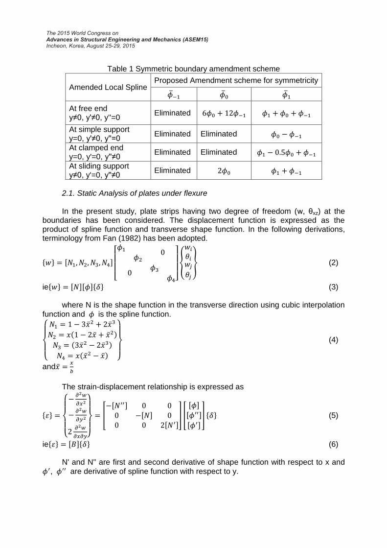
Table 1 Symmetric boundary amendment scheme
Amended Local Spline Proposed Amendment scheme for symmetricity
At free end y≠0, y'≠0, y''=0
Eliminated
At simple support y=0, y'≠0, y''=0
Eliminated Eliminated
At clamped end y=0, y'=0, y''≠0
Eliminated Eliminated
At sliding support y≠0, y'=0, y''≠0
Eliminated
2.1. Static Analysis of plates under flexure
In the present study, plate strips having two degree of freedom (w, θxz) at the boundaries has been considered. The displacement function is expressed as the product of spline function and transverse shape function. In the following derivations, terminology from Fan (1982) has been adopted.
* + , -
[
]
{
} (2)
ie* + , -, -* + (3) where N is the shape function in the transverse direction using cubic interpolation
function and is the spline function.
{
( )
( )
( ) }
(4)
and
The strain-displacement relationship is expressed as
* +
{
}
[ , -
, - , -
] [
, -
, -
, -] * + (5)
ie* + , -* + (6) N' and N'' are first and second derivative of shape function with respect to x and
, are derivative of spline function with respect to y.

The stress-strain relation is expressed as linear stress-strain relationship of thin orthotropic plate given as
* + {
} [
]
{
}
(7)
ie* + , -* + (8) where
{
( )
( )
}
(9)
, are the Young's modulus, , are Poisson's ratio and Gxy is the
shear modulus The stiffness matrix is developed similar to finite element procedure as shown in Eq 10.
, - ∫ , - , -, -
∫ ,, - , - , - -
[
, -
, -
, - ]
[
] [
, -
, -
, - ] [
, -
, -
, -] (10)
The development of load matrices are also similar to finite element procedure except the fact that the spline functions is also included in the formulation. For uniformly distributed load
* + ∫ ∫ , - , - * ( )( )+
(11)
Here b is the width of the plate strip, q1 is the uniformly distributed load, q2 is the variation from uniformly distributed load, y1 and y2 are the distances of linear variation in load from q1 to q2. For a concentrated load, the load point has to pass through the nodal line. Otherwise the effect of load point has to be transferred to boundary nodal lines using cubic interpolating polynomial. The load matrix is given as

* + , ( )- {
} , ( )- {
} , ( )- {
} (12)
The overall stiffness and load matrix are formulated by assembling strip stiffness and load matrix. After applying the boundary conditions, the stiffness equations are solved using factorization method to obtain the displacement at section knots. Substituting the knot displacements in strain-displacement and stress-strain relation, the knot forces and moments are obtained.
2.2. Buckling Analysis of plates under axial compression Applying the total potential energy principle on to the equilibrium equation, the stiffness equation can be formulated as (, - , -)* + (13) where K is the elastic stiffness matrix as explained in section 2.1 and G is the geometric stiffness or stability matrix. The increase in potential energy of the membrane forces resulting from flexural buckling developed by Plank (1974) given as
∫ ∫ { .
/
.
/
}
(14)
( ) ⁄ (15) Here a, b and t are the length, width and thickness of the strip respectively and
, , ,and are the stresses acting on the plate as shown in Fig. 2.
Fig. 2 Basic membrane stresses in a plate strip
The geometric stiffness matrix corresponding to longitudinal compression, transverse compression and shear is shown in Eq 16 to 18. The total geometric stiffness matrix is the summation of these three matrices. The Eigen value equations are solved using Jacobi iteration technique to obtain the critical buckling stresses.

, - ∫ ∫ , -
, - ( ( ) ⁄ ), -
, -
(16)
, - ∫ ∫ , - , -
, -
, -
(17)
, - ∫ ∫ , - , -
, -
, -
(18)
3. ANALYSIS OF PLATES USING SPLINE FINITE STRIP METHOD A spline finite strip code is developed in FORTRAN-90 for the static and buckling analysis of plates under various boundary and loading conditions. The result of the SFSM is compared with theoretical solutions available in Timoshenko (1961).
3.1. Simply supported plate under uniformly distributed load A simply supported plate has been analysed under uniformly distributed loading. The boundary conditions are imposed on longitudinal ends by the proposed amending boundary splines and other ends similar to finite element procedure. The numerical solution for mid deflection of plate agrees well with theoretical solution as shown in Table 2. Convergence study has been done by increasing the number of strips (n) in x direction and number of sections (m) in y direction. It has been observed that as the aspect ratio (a/b) of the plate increases, the numerical solution converges to theoretical solution at a faster rate (Fig. 3). Table 2 Comparison of SFSM and theoretical solutions for simply supported plate with
uniformly distributed load
Size of Plate
a/b t(mm) q
(N/mm2)
k Percentage variation
(%) a
(mm) b (mm) SFSM Theoretical
400 400 1 2.5 0.1 0.407 0.406 0.25
480 400 1.2 2.5 0.1 0.563 0.564 -0.18
560 400 1.4 2.5 0.1 0.703 0.705 -0.28
720 400 1.8 2.5 0.1 0.933 0.931 0.21
800 400 2 2.5 0.1 1.014 1.013 0.10
1200 400 3 2.5 0.1 1.224 1.223 0.08
1600 400 4 2.5 0.1 1.282 1.282 0.00
2000 400 5 2.5 0.1 1.297 1.297 0.00
Mid span deflection,
Where k=constant, q = uniformly distributed load, b = width, a= length and t= thickness of the plate and D = flexural rigidity of plate, E = modulus of elasticity (2 x 10⁵ N/mm2) and ν=poisson's ratio (0.3).

Fig. 3 Convergence of SFSM solution with increase in spline sections
3.2. Fixed plate under uniformly distributed load The analysis of fixed plate under uniformly distributed load is shown in Table 3. The SFSM is able to predict the behaviour of plate accurately and mid span deflection is in close agreement with theoretical solution. The solution also converges at a faster rate as the aspect ratio of plate increases.
Table 3 Comparison of SFSM and theoretical solutions for fixed plate with uniformly distributed load
Size of Plate
a/b t(mm) q
(N/mm2)
k Percentage variation
(%) a (mm)
b (mm)
SFSM Theoretical
400 400 1 2.5 0.1 0.127 0.126 0.79
480 400 1.2 2.5 0.1 0.172 0.172 0.00
560 400 1.4 2.5 0.1 0.208 0.207 0.48
640 400 1.6 2.5 0.1 0.231 0.23 0.43
720 400 1.8 2.5 0.1 0.245 0.245 0.00
800 400 2 2.5 0.1 0.254 0.254 0.00
Mid span deflection,
3.3. Simply supported plate with point load at centre SFSM analysis of simply supported plate with concentrated load at centre is done for various plate aspect ratios and the comparison of deflection at centre is shown in
0.95
1.00
1.05
1.10
0 20 40 60
wsf
sm/w
analy
tica
l
Number of spline sections
a/b=1
a/b=1.4
a/b=2
a/b=5

Table.4. Like uniformly distributed load, the SFSM is able to predict the behaviour of plate under concentrated loading. Table 4 Comparison of SFSM and theoretical solutions for simply supported plate with
concentrated load at centre
Size of Plate
a/b t(mm) P(kN)
k Percentage variation
(%) a (mm)
b (mm)
SFSM Theoretical
400 400 1 2.5 10 0.012 0.012 0.00
480 400 1.2 2.5 10 0.014 0.014 0.00
560 400 1.4 2.5 10 0.015 0.015 0.00
640 400 1.6 2.5 10 0.016 0.016 0.00
720 400 1.8 2.5 10 0.016 0.016 0.00
800 400 2 2.5 10 0.017 0.017 0.00
1200 400 3 2.5 10 0.017 0.017 0.00
Mid span deflection,
3.4. Buckling analysis of plate The analysis of plate under static loading has been extended to buckling analysis by including geometric stiffness matrix on to the SFSM formulation. The critical buckling stress of plate under different boundary and loading conditions for various aspect ratios are calculated using SFSM and the buckling coefficient (k) is shown in Fig. 4 and comparison of critical buckling coefficient with theoretical values for aspect ratio (a/b) 1 is shown in Table 5. The SFSM solution is in agreement with theoretical solutions, with a faster convergence than static analysis.
Table 5 Comparison of buckling coefficient between SFSM and theoretical values (a/b=1)
Loading and boundary condition ksfsm ktheoretical Percentage variation (%)
Uniaxial compression-simply supported 4.001 4 0.025
Uniaxial compression-fixed 10.252 10.07 1.807
Biaxial compression-simply supported 2.001 2 0.050
Biaxial compression-fixed 5.335 5.315 0.376

Fig. 4 Comparison of buckling coefficient under various loading and boundary conditions
3. CONCLUSIONS A spline finite strip program has been developed for the static and buckling analysis of plates. Spline amendment scheme has been proposed in this paper for various boundary conditions, which retains the symmetricity of stiffness matrix. The developed code is able to accurately predict static and buckling solutions, converging to theoretical solutions with moderate strip discretization. The program can be extended for static, buckling and nonlinear analysis of cold-formed steel members of various cross sectional shapes. REFERENCES Fan, S.C. (1982), "Spline finite strip in structural analysis." PhD. thesis, University of
Hong Kong, China. Gutkowski, R. M., Chen, C. J. and Puckett, J. A. (1991), “Plate bending analysis by
unequally spaced splines.” Thin-walled Struct., Vol. 11 (5), 409-430. Hancock, G. J., Davids, A. J., Key, P. W., Lau, S. C. W. and Rasmussen, K. J. R.
(1990), “Recent developments in the buckling and nonlinear analysis of thin-walled structural members.” Thin-walled Struct., Vol. 9 (1-4), 309-338.
Kwon, Y. B. and Hancock, G. J. (1991), “A nonlinear elastic spline finite strip analysis for thin-walled sections.” Thin-walled Struct., Vol. 12 (4), 295-319.
Lau, S. C. W. and Hancock, G. J. (1986), “Buckling of thin flat walled structures by a spline finite strip method.” Thin-walled Struct., Vol. 4 (4), 269-294.
Lau, S. C. W. and Hancock, G. J. (1989), “Inelastic buckling analyses of beams, columns and plates using the spline finite strip method.” Thin-walled Struct., Vol. 7 (3-4), 213-238.
0
5
10
15
20
25
30
35
40
0 0.5 1 1.5 2
Buck
ling c
oeff
icie
nt
(k)
a/b
Uniaxial-ss
Uniaxial-fixed
Biaxial-ss
Biaxial-fixed

Pham, C. H. and Hancock, G. J. (2013), “Shear buckling of channels using the semi-analytical spline finite strip methods.” J. Construct. Steel Res., Vol. 90 (11), 42-48.
Plank, R.J. and Wittrick, W.H. (1974), "Buckling under combined loading of thin flat-walled structures by a complex finite strip method." Int. J. Num. Meth. Eng., Vol. 8(2), 323-339.
Timoshenko, S.P. Gere, J.M. (1961), Theory of elastic stability, McGraw-Hill, New York. Yao, Z. and Rasmussen, K. J. R. (2011a), “Material and geometric nonlinear
isoparametric spline finite strip analysis of perforated thin-walled steel structures—Analytical developments.” Thin-walled Struct., Vol. 49 (11), 1359-1373.
Yao, Z. and Rasmussen, K. J. R. (2011b), “Material and geometric nonlinear isoparametric spline finite strip analysis of perforated thin-walled steel structures—Numerical investigations.” Thin-walled Struct., Vol. 49 (11), 1374-1391.