state of oklahoma department of … · department of transportation . geotechnical specifications...
TRANSCRIPT

Page 1 of 16
STATE OF OKLAHOMA DEPARTMENT OF TRANSPORTATION
GEOTECHNICAL SPECIFICATIONS FOR ROADWAY DESIGN
June 29, 2011 ( Revised July 2, 2015 )
GENERAL: These specifications provide the procedures for obtaining the geotechnical information, for highway design and construction, required by the Roadway Design Division of the Oklahoma Department of Transportation (ODOT). These specifications include the general guidelines for conducting geotechnical investigations and are governed by the “Geotechnical Engineering Circular No. 5 - Evaluation of Soil and Rock Properties”, FHWA-IF-02-034, April 2002, the most current AASHTO and ASTM test procedures, and AASHTO R-10.
Geotechnical information is obtained through subsurface investigations, field tests, and the corresponding laboratory tests conducted on samples obtained in the field. Direction and oversight of these operations are provided by the Geotechnical Engineer with day to day coordination through the project geotechnical specialist.
A Geotechnical Engineer is a registered professional engineer with geotechnical expertise. A geotechnical specialist is a civil engineer, geologist, engineering geologist, or a trained, experienced, qualified individual that has been certified by the ODOT Materials Division or other approved designated authority.
The Geotechnical Engineer is required to submit a boring, sampling, and testing plan to ODOT for approval prior to beginning the subsurface exploration in order to resolve all matters with regard to sampling, testing and analysis of data. The Department’s geotechnical policies and procedures will represent the state of the practice and will govern.
In conducting geotechnical investigations, the Geotechnical Engineer is responsible for and will be compensated for the following items of work:
• Securing right-of-way
• Filing and obtaining U.S. Army Corps of Engineers Wetland Permits.
• Locating and marking utility crossings, with OKIE, where borings, test pits, or trenches are required in the geotechnical investigation.
• Planning and arranging for traffic control when required in conducting the geotechnical investigation. Traffic control is to be subcontracted outside of ODOT and is required to meet the most current Manual on Uniform Traffic Control Device Specifications during the geotechnical investigation.
• Provide the required location of all test borings and pavement core locations conducted in the preliminary soil surveys, detailed soil investigations and geological investigations. The survey shall be referenced to plan station and offset from the centerline of survey, construction reference line (CRL) or base line given on the project plans. If the project is a

Page 2 of 16
new alignment that is beyond the reasonable reach by a measuring tape of 100 ft. from a reference line, then a supplemental survey contract may be approved.
• Dozer services required for access to test boring locations.
• Borehole closing when applicable.
SCOPE: The geotechnical investigation shall consist of performing all or parts of the following surveys and investigations required by the Roadway Design Division of ODOT and as directed by ODOT at the time of contract negotiations.
PRELIMINARY SOIL SURVEYS
1. Pedological and Geological Survey: A Pedological and Geological Survey is required for new highway alignments, new construction parallel to existing highway alignments, and new construction requiring a raising of the grade on and above existing highway alignments. A Pedological Soils Survey is reliant on knowledge of the soil series mapping units and the corresponding taxonomic classification system established by the Natural Resources Conservation Service (NRCS). More detailed information about Pedological Soil Surveys and the NRCS Soil Classification System are provided in Appendix 1. The general procedures for conducting the Pedological activities are presented below in option A and option B as directed. This includes the procedures for sampling and testing. Option A
a. The pedological survey requires plotting the Center Reference Line (CRL) or the Centerline (CL) for the proposed highway alignment on the appropriate U.S. Department of Agriculture Soil Conservation (SCS) county soil survey report map sheet(s). The map units are delineated on aerial photographs that comprise the aforementioned sheets. They are usually scaled at 1:20,000 and occasionally 1:24,000; either is acceptable. The plotting procedure is also used to establish the length of each soil series map unit (soil phase) as the alignment crosses the map unit delineation. These lengths or distances are to be summed and provided in the report. The CRL and CL locations are taken from the project plans. In the case of soil series complexes, as map units, e.g. Niotaze-Darnell, each series is to be located and treated separately. The type and degree of assistance, as well as the names of the NRCS, or other soils scientist(s) personnel rendering assistance, shall be documented and referenced in detail.
b. Take adequate sample quantities at the site of each soil series to ensure proper testing of each soil horizon as well the composite bulk sample(s). Pits are acceptable and may be a preferred method. These are to be made along the CRL or CL or referenced to them. If the map unit repeats within the alignment, it need not be resampled, if the series is confirmed by boring to be the same.

Page 3 of 16
c. A composite bulk sample is defined as a mixture of the total depths (thicknesses) of each of the B and C horizons. For example, if a soil series description lists the B horizons as Bt1, Bt2, Btk, Bt3, and B/C, these together will constitute one composite “B” bulk sample. Subsequently, the C/B and C horizons will constitute a second bulk sample “C”, for soil series that contain those particular horizons. In the event that the map unit does not have a B horizon but has an A/C horizon instead, the composite bulk sample shall be taken of the total depth of horizons listed below the A horizon e.g. the A/C or B/C horizon. It is important that the bulk sample be a well blended mixture of soils that are representative of all the respective horizons in the composite sample. In most cases, soil map unit revisions and recorrelations have probably been made to at least a few of the map units encountered along the CRL. This new information is available at the local NRCS field offices, usually located in the county seat or the NRCS State Soil Scientist in Stillwater OK. The NRCS Web Soil Survey, http://websoilsurvey.nrcs.usda.gov/app/ is also a good source for county soils maps and information. Copies of all official soils series descriptions, including the new recorrelated series are required for inclusion in the Pedological report.
d. Use the soil map unit with its associated current official soil series description and classification as a guide for sampling and other engineering interpretations. For example, the official description of Kirkland clay loam, 0 – 1% slope; Fine mixed, superactive, thermic Udertic Paleustoll, 6/99, is to be used as a guide for sampling. The Fine mixed, superactive, thermic, Udertic Paleustaoll is the soil series taxonomic description. It consists of the order, suborder, great group, subgroup modifier, particle size, mineralogy, and soil temperature. In this description the typical thickness of the A horizon is 8 inches, the Btl horizon is typically 8 to 19 inches thick, the 2Bt3 is 75 to 82 inches thick, etc. In the map unit of interest, the depths and thickness of the subhorizons may vary from that of the description given in the county soil survey report and/or in the official soil series description. However, they must be within the “Range in Characteristics,” as described in the official soil series description (OSD). A Soil Taxonomy Statement is required for each soil series consisting of a written interpretation of each taxonomy description sub-part for a total of seven parts. Guidelines for preparing the Soil Taxonomy Statement are included in Appendix 1.
e. There may be inclusions of a contrasting or similar soil series within the map unit being sampled. They may be listed and described in the “Competing Series” or the “Geographically Associated Soils” paragraphs in the official soil series descriptions. Select the best-fit soil series description from this list, if possible, for the inclusion in the report.
f. Laboratory tests required for all representative subhorizon samples for each soil series are as follows:
1. Plastic Limit, AASHTO T90 2. Liquid Limit, AASHTO T89 3. Gradation required for complete soil classification, AASHTO T88 4. pH, AASHTO T289 5. Electrical Resistivity, AASHTO T288

Page 4 of 16
6. Soluble Sulfates, for projects in ODOT Field Divisions 4,5,6,&7, OHD L-49
g. Laboratory tests required for the bulk composite sample for the B and C horizons of each soil series are as follows:
1. Plastic Limit, AASHTO T90 2. Liquid Limit, AASHTO T89 3. Gradation required for complete soil classification, AASHTO T88 4. Moisture-Density, AASHTO T99 – (include a minimum of 5 points) 5. Resilient Modulus, AASHTO T307 6. Soluble Sulfates, for projects in ODOT Field Divisions 4,5,6,&7, OHD L-49
h. The geologic portion of this survey shall consist of the inclusion of a representative
sample of the R horizon. A geologic statement describing the R horizon in geological terminology shall be included in the report. If the R horizon is shale it shall be sampled and subjected to the soil laboratory tests listed under paragraph “f” above. The terminology for describing the R horizon material shall be taken from the “Standard Guide for the Description of Surface and Subsurface Geological Rock Formations of Oklahoma” found in Appendix 3.
i. The quantities of soil required for the tests are provided in AASHTO R-13.
j. Personnel requirements. The person performing the pedological soil survey and providing the report shall hold a Bachelor of Science (BS) degree in Soil Science. The person may hold a BS in a natural science (i.e. geology or forestry) provided the natural science has a minimum of 30 credit hours of natural sciences with 15 of those hours in soil science. Alternatively, a resume of pertinent education and experience shall be submitted to the Geotechnical Engineer of the Oklahoma Department of Transportation for review and approval.
Option B
The CRL or centerline of the proposed project is to be plotted on the soil survey map as in Option A. The soil series are to be organized by the Soil Taxonomy Order. The most predominant soil series (largest lineal extent) for each Order in the project extent is to be sampled and tested as required in Option A
2. Shoulder Soil Survey: A Shoulder Soil Survey is required for the widening of existing
pavement at grade. This survey shall apply to the adding of shoulders, lanes and medians to existing pavements. The general procedure for conducting the shoulder soil survey is as follows:
a. The sampling location shall be within the station extents of the widening section using the average width of the improvement and a sampling interval of 500 feet. Sample locations shall apply to all widening extents as detailed in the project plans, i.e., outside pavement shoulder, both pavement shoulders (in the case of two-lane highway or street), inside shoulder (in the case of four-lane highway or street), and in median areas.
Page 5 of 16
b. The sampling depth shall be 36 inches consisting of the top 6 inches and the bottom 30 inches provided that there is a reasonable consistency and similarity of material. If different material is encountered in the bottom 30 inches, subdivide the layers and include a sample from each layer.
c. Report the extent(s) of similar soil classifications within the station extents of the project.
d. Record the depth of groundwater or perched water zones measured from the top of ground elevation at the end of drilling.
e. A composite bulk sample(s) of the full sampling depth representative of the whole project extent or of each different soil extent as identified in item 2c.
f. Laboratory tests required of all sample interval depths and/or soil layers are as follows:
1. Plastic Limit, AASHTO T90 2. Liquid Limit, AASHTO T89 3. Gradation required for complete soil classification, AASHTO T88 4. Moisture-density, AASHTO T99 5. Resilient modulus, AASHTO T307 6. Soluble Sulfates, for projects in ODOT Field Divisions 4,5,6,&7, OHD L-49
g. Guidelines for quantities of soil samples are given in AASHTO R13
3. In Place Soil Survey: The In Place Soil Survey is required for new construction when the design calls for separation of the grading and paving contracts. It may also be used to evaluate the subgrade of existing pavement sections which are to be reconstructed with no change in grade or alignment. The general procedure for conducting the In Place Soil Survey is the same as for the Shoulder Soil Survey with the following exceptions:
a. The sampling interval for grading projects is 1000 ft. or wherever there is a visual change in soil types. Sampling locations for existing pavement sections will most likely be project specific such as at a bridge approaches and underpasses.
b. The sampling depth shall be 36 inches unless otherwise noted. Sample and test the different soil types encountered in the boring and record the extent(s) of similar soil classifications within the station extents of the project.
4. Pavement and Subgrade Soil Survey: A Pavement and Subgrade Soil Survey is required
when the properties of an existing pavement structure and the underlying subgrade soils are needed for evaluation of the pavement load capacity and for an overlay design. The Falling Weight Deflectometer (FWD) is required for evaluating the pavement structure (surface, base, and subbase). The general procedure for conducting pavement deflection tests shall meet all requirements of the ASTM D4694 and D4695 with the following additional requirements:

Page 6 of 16
a. FWD tests are to be conducted in the outside wheel path in a staggered pattern at a spacing of 250 feet along the highway centerline. Additional requirements for the FWD analysis are as follows:
1. The FWD is to be operated during a time frame of April through November or when the ambient temperature has been a minimum of 45 degrees for 3 successive days prior to and during the testing operations.
2. The air and pavement temperatures are to be recorded by the FWD equipment for each test location and according to ASTM D4695, Subsection 7.1.5.
3. At each FWD test location, the test procedure shall be according to ASTM D4694, Subsection 9. Load and deflection sensors are to be in current calibration at the time of testing, as required by ASTM D4694, Subsection 8. Deflection testing shall include 2 seating drops and 4 recording drops per test location. The test load for the 4 recording drops are based upon highway classification; Interstate highways will be tested with a 15,000 lb. load, U.S. designated highways will be tested with a 12,000 lb. load, State highways will be tested with a 9,000 lb. load, Local and County roads will be tested with a 7,500 lb. load.
b. Back calculation analysis of the pavement section shall be made using the most current edition of the Modulus program. For asphalt pavement sections, provide the back calculated resilient modulus of the subgrade and the elastic modulus of the composite pavement structure. For concrete pavement sections, provide the modulus of subgrade reaction, the pavement section thickness, and the pavement condition as determined according to the survey described in item 5d. A copy of the FWD report shall be submitted, in Microsoft Excel Format, electronically to the ODOT Pavement Engineer.
c. A minimum of five pavement cores per mile (more if there is an obvious change in pavement structure) shall be taken to document the thicknesses, types, and condition of the payment layers. Take the cores at FWD test locations. Provide a digital, color photograph of each core with scale. Record the layer thicknesses and the degree of stripping or deterioration of asphalt pavement cores. Record honeycomb, deterioration cracking (D-Cracking), and separations in concrete pavements. Examples of the required core logs are provided in Appendix 5. Cores shall be taken in the middle of the slab in PCC Pavements. Ground Penetrating Radar may be used to reduce the number of cores taken to accurately determine the pavement section profile.
d. Pavement surface condition shall be described according to the distress patterns as detailed in the FHWA publication No. FHWA-RD-03-031 “Distress Identification Manual for the Long Term Pavement Performance Program”.
Page 7 of 16
e. For plain jointed, rigid pavements, joint efficiency shall be tested in each direction, in the right wheel path of the right lane, every 600 feet (180m) at the transverse contraction joint. A core shall be cut through the joint at the test site and the core condition reported.
f. The pavement subgrade shall be sampled to a depth of 36 inches below existing pavement. Dynamic Cone Penetration tests, DCPT, may be requested to further evaluate the strength and consistency of the subgrade.
g. Report the extent(s) of similar subgrade soils within the station extents of the project.
h. Record the depth of groundwater or perched water zones measured from the top of ground elevation at the end of drilling.
i. Laboratory tests required of granular bases, subbases, and subgrade soils are as follows:
1. Plastic Limit, AASHTO T90 2. Liquid Limit, AASHTO T89 3. Gradation required for complete soil classification, AASHTO T88
j. Guidelines for quantities of soil samples are given in AASHTO R13.
5. Borrow Pit Investigation: A borrow pit investigation is required where selective subgrade topping is requested. The specifications for selective subgrade topping are provided in the most current issue of the ODOT Standard Specifications for Highway Construction, Section 202.02 B.
a. The size of the borrow pit shall be based on plan estimates of borrow quantities needed.
b. A borrow pit location within a 30-mile haul distance of the project is acceptable.
c. As a minimum requirement, a boring shall be drilled at each geometric corner and two near the center. A minimum depth of ten feet per boring shall be analyzed for select material.
d. Record the depth of groundwater or perched water zones measured from the top of the ground elevation at the end of drilling.
e. If the borrow source is rock, investigate the rippability by use of seismic velocity. Refer to the seismic velocity charts found in the Appendix 3 to estimate the rippability of rock.
f. If the borrow sources can be select graded in a cut section of the proposed project site, the above items c. through e. all apply.
g. If a borrow source is unavailable, then a pavement layer requiring borrow may be substituted with an equivalent layer of chemically stabilized soil or a soil-aggregate blend.

Page 8 of 16
h. Soils that are to be placed within the top 2 ft. of the grading section shall be tested for soluble sulfates according to OHD L-49.
i. Laboratory tests required of borrow pit soil samples are as follows:
i. Plastic Limit, AASHTO T90 ii. Liquid Limit, AASHTO T89
iii. Gradation required for complete soil classification, AASHTO T88 iv. Soluble Sulfates, for projects in ODOT Field Divisions 4,5,6,&7, OHD L-49
6. Resilient Modulus Tests: Resilient modulus testing is required for the pavement design of
all State and Federal Aid highway projects. This test is conducted, according to the requirements of AASHTO T-307, on composite bulk samples obtained in Pedological, Shoulder, and In Place Soil Surveys. Resilient Modulus testing for ODOT shall be conducted by a qualified technician having a minimum of 2 years continuous experience in resilient modulus testing. ODOT requires two resilient modulus tests for each composite sample: For A-1 to A-5 Soils:
• One test at 95 % of maximum dry density, optimum moisture content • One test at 95 % of maximum dry density, 2 % wet of optimum moisture content.
For A-6 to A-7 Soils: • One test at 95 % of maximum dry density, optimum moisture content • One test at 95 % of maximum dry density at the corresponding moisture content at
which 95% dry density intersects the wet side of the moisture/density curve.
7. Laboratory Tests: All laboratory tests required for the Preliminary Soil Surveys shall be performed by technicians certified by the Highway Construction Materials Certification Board in a laboratory qualified by the ODOT Materials Division.
DETAILED SOIL INVESTIGATION: A detailed Soil Investigation is required for analyzing the geotechnical problems related to roadway designs. These geotechnical problems include embankment and foundation soil settlement and stability, cut and natural slope stability, problem soils related to roadway subgrades and embankments, roadway structures, and construction recommendations. A detailed soil investigation of these problems is required in conjunction with the Pedological and Geological Survey. The interpretation and judgment of the pedological and geological site conditions is the responsibility of the Geotechnical Engineer.
1. Embankment and Foundation Soil Settlement and Stability (Embankments Between 0-10 feet Above Natural Ground Line): Estimates of embankment and underlying foundation soil settlement, slope stability and design slopes are required. These estimates are made by assuming reasonable parameters for anticipated embankment and foundation soils based

Page 9 of 16
on the soil series types occurring within the project extent. These estimates are required for embankments crossing each soil series encountered along the project alignment. Use NAVFAC D 7.01 to determine estimates of reasonable soil parameters for anticipated embankment and foundation soils as described by the pedological soil units.
2. Embankment and Foundation Soil Settlement and Stability (Embankments Greater Than 10 Feet Above Natural Ground Line): Estimates of embankment and underlying foundation soil settlement and stability are required. Borings are to be typically spaced every 200 feet (erratic conditions) to 500 feet (uniform conditions), with at least one boring made in each Pedological soil unit. The primary borings are to be Standard Penetration Test (SPT) borings. These borings, which are for obtaining soil samples and information, should be supplemented with in situ field tests such as the Cone Penetration Test (CPT) or the Flat Plate Dilatometer Test (DMT) to obtain additional information for determining the soil and rock subsurface conditions as follows:
a. Stratigraphy
1) Physical description and extent of each stratum
2) Thickness and elevation of top and bottom of each stratum
b. For cohesive soils (each stratum)
1) Natural moisture contents
2) Atterberg limits
3) Presence of organic materials
4) Evidence of desiccation or previous soil disturbance, shearing or slickensides
5) Swelling characteristics
6) Shear strength
7) Compressibility – NOTE: The Standard Penetration Test is not to be used for shear strength or compressibility analysis in cohesive soils. Shear strength and compressibility can be determined by laboratory consolidation tests conducted on undisturbed soil samples or by in situ field tests such as the Cone Penetration Test (CPT) or the Flat Plate Dilatometer Test (DMT).
c. For granular soils (each stratum)
1) In-situ density (average and range) typically determined from Standard Penetration Tests (SPT) or Cone Penetration Tests (CPT)
2) Grain-size distribution (gradation)
3) Presence of organic materials
d. Ground water (for each aquifer if more than one is present)
1) Piezometric surface over the site area, existing, past, and probable range in future (observation at several times.)
2) Perched water table

Page 10 of 16
e. Bedrock
1) Depth and elevation over the entire site
2) Type of rock (Lithology)
3) Extent and character of weathering
4) Joints, including distribution, spacing, whether open or closed, and joint filing.
5) Faults
6) Solution features in limestone or other soluble rocks
7) Core recovery and soundness (RQD)
f. Engineering Analysis. The minimum guidelines required for engineering analysis, based upon soil classification, are given in Table 1 of Appendix 2. Additional guidelines should be noted for the following conditions:
1) When soft ground is encountered (SPT ‘N’ Resistance < 4), conduct in situ tests and/or undisturbed sample exploration in each soil series mapping unit. Conduct continuous in situ tests and/ or undisturbed sampling throughout the foundation soils until firm material (SPT ‘N’ Resistance > 30) or rock is encountered.
2) When medium stiff to very stiff (5 < SPT ‘N’ resistance < 30) is encountered, follow the minimum sampling and testing criteria in Table 2 of Appendix 2.
3) If rock is encountered within a depth equal to twice the embankment height, conduct continuous rock coring as detailed in Table 2 of Appendix 2.
4) Groundwater investigations shall be made according to Table 2 of Appendix 2.
5) For bridge embankment headers, conduct a detailed study of the embankment and foundation soils within 200 feet back and 200 feet forward of each bridge abutment.
3. Cut and Natural Slope Stability: Cut slopes greater than 30 feet below the natural ground line in soil shall be analyzed for both end of construction and long germ slope stability conditions. If slope materials are overconsolidated (OCR > 2) then the residual shear strength shall be used in the long term slope stability analysis. Soils coming from cuts that will be placed within the top 2 ft. of the grading section shall be checked for soluble sulfates according to OHD L-49.
4. Problem Soils Related to Roadway Subgrades and Embankments: Additional field exploration, laboratory testing and analysis are required to determine the long-term performance and/or suitability of the following soil and rock that may be incorporated into the roadway subgrade and embankment or found in the foundation soils below the roadway embankment:
a. Organic soils
b. Normally consolidated clays
c. Expansive clays and shales
d. Dispersive soils
Page 11 of 16
e. Collapsible soils
f. Degradable shales
g. Caliche
h. Mine spoils (all types) and caves
i. River or stream meander loops and cutoffs and ox-bow lakes
j. Karst features (e.g., gypsum, limestone)
These soils and conditions are coordinated with the Pedological and Geological Survey and Borrow Pit Investigation. The interpretation and judgment of these soil conditions is the responsibility of the Geotechnical Engineer.
5. Roadway Structures: Check the bearing capacity, settlement and stability of roadway structures (i.e. retaining walls) according to the most current AASHTO Standard Specifications for Highway Bridges.
6. Construction Recommendations: The Geotechnical Engineer may recommend chemically stabilized bases, subbases and subgrades as directed by ODOT or in lieu of select borrow requirements of the most current edition of the Oklahoma Department of Transportation (ODOT) Standard Specifications for Highway Construction. These recommendations are limited to lime, fly ash, CKD, and Portland cement and the method of evaluation shall follow ASTM D4609, OHD L-50 and OHD L-51.
GEOLOGICAL INVESTIGATION: A Geological Field Investigation is required for any or all of the following:
1. rock cuts of 10 feet or greater 2. shallow rock mapped within a proposed cut section 3. rock mechanics analysis 4. geological hazards 5. rock fills
A geological field investigation may consist of the following elements:
1. borings 2. slope stability analysis 3. rippability ratings 4. evaluation of geological hazards 5. shear strength of rock fills 6. evaluation of excavated rock for use as a source of aggregate 7. Geological statements.
The Geological Investigation is in conjunction with the Pedological and Geological Survey. Dimensions are to be in English or metric units, whichever is compatible with the Plans. Any interpretations and judgements made of the site geologic conditions are the responsibility of the Geotechnical Engineer. The investigation may include the following:

Page 12 of 16
1. Borings: Space borings through cut sections within the project extent every 100 feet in the longitudinal centerline (CL or CRL) direction. Provide a minimum of two borings along a straight line perpendicular to the centerline or planned slope face to establish a geological cross-section of the cut. Two of these borings shall be continuously cored to characterize the soil and/or rock properties. The depths of all borings are to extend a minimum of 10 feet below the deepest plan grade. Record the location of perched or permanent water tables for a minimum of 24 hours.
2. Seismograph Surveys: Seismograph Surveys of cut sections may be required. The equipment must be capable of determining rock properties throughout the entire depth of the cut, plus 10 feet below plan grade. Depths to each rock layer must be accurate to the nearest foot.
3. Rock Stability Analysis: Rock stability analysis is required when the dip of the geological formation exceeds 20 degrees into the slope face. Ensure the analysis meets all the requirements of the kinematic slope stability program, RockPack III (or equivalent), using the stereographic projection procedure. This analysis is necessary to determine the slope stability of closely spaced (2 ft. or less) rock joints (fractures) and/or tilted (dipping greater than 10 degrees) rock strata of the cut slope. These measurements will allow development of the local structural geology, in three dimensions, required for making this analysis. The data that is required for this analysis is the dip, and dip direction of both the rock strata and of the joints (fractures) in the rock. The equipment necessary to obtain the dip, and joint orientation data is a Clar and/or Brunton compass. This device gives magnetic headings and dip angles. Trenching or oriented cores may be necessary in order to expose enough rock strata to make the measurements. The shear strength of the jointed rock shall be based on the requirements of the Hoek-Brown (1988) criteria. If the observations identify joints (fractures) in which shear failures may occur, or fractures that contain soil infilling; then, the shear strength of the infilling or fractures is required to be taken into account in the overall slope stability analysis. In argillaceous massive shales (non-laminar), slope stability analysis shall be based on the use of a soil mechanics approach.
4. Rippability: Determine rippability by a refraction seismograph. The seismograph must be capable of providing valid, useable signals for calculating the depth to bedrock to nearest foot. It must be capable of sensing rock layers to the depth of the proposed cut. Calculations of rock rippability shall be made from the resulting sound wave velocities. The rock rippability rating of each layer shall be reported as rippable, marginal, or non-rippable .
5. Geologic Hazards: Identify any geologic hazards (e.g. sinkholes, landslides, and others). These are to be precisely located and dimensioned to the nearest foot. Record all occurrences in the final report. GPS coordinates may be used in addition to Public Land Survey legal descriptions. Locations must be referenced to the CL or CRL by plan station and offset.
6. Rock Fill Embankments: Determine the shear strength values of rock fill embankments. The model will be generated by using the results of the triaxial shear tests. Conduct the testing on 1-in. size aggregates from the specified rock fill aggregate source.
7. Geologic Site Assessment: Provide a geologic site assessment of the rock type and layering conditions in the cuts along the CL or CRL. This report will be based on available geologic maps, bulletins etc., along with a field, on-site investigation. The assessment will pertain to

Page 13 of 16
the geologic conditions and character of the rock strata as provided in the above geologic information sources.
8. Equipment: List the equipment used to make the observations (e.g. borings, seismograph surveys, rippability, and stability analysis) in the report. Provide the make, model, and manufacturer.
Descriptive Terminology and Rock Classification: The descriptive terminology and rock classification shall be based upon the “Standard Guide for the Description of Surface and Subsurface Geological Rock Formations of Oklahoma” as presented in Appendix 3. The finished boring log shall be a compilation of all classification and description from laboratory tests and field logging.
GEOTECHNICAL EXPLORATION, IN SITU TEST PROCEDURE: 1. The most current issue of the following ASTM Standards for in situ testing will govern and
shall be used. a. Standard Test Method for Standard Penetration Test (SPT) and Split-Barrel Sampling
of Soils – ASTM D1586 b. Electronic Friction Cone and Piezocone Penetration Testing of Soils – ASTM D5778 c. Mechanical Cone Penetration Test – ASTM D3441 d. Flat Plate Dilatometer Test – ASTM D 6635 e. Pressuremeter Test – ASTM D 4719 f. Vane Shear Test – ASTM D 2573 g. Dynamic Cone Penetrometer Test – ASTM D 6951
2. The most current issue of the following ASTM and AASHTO Standards for sampling will
govern and shall be used. a. Standard Test Method for Standard Penetration Test (SPT) and Split-Barrel Sampling
of Soils – ASTM D1586 b. Practice for Thin-Walled Tube Geotechnical Sampling of Soils – ASTM D1587 c. Practice for Rock Core Drilling and Sampling of Rock for Site Investigation – ASTM
D2113 d. Practice for Preserving and Transporting Soil Samples – ASTM D4220 e. Collection and Preservation of Water Samples – AASHTO R24 f. Standard Test Method for Determining Subsurface Liquid Levels in Borehole or
Monitoring Well ( Observation Well) – ASTM D4750
3. Bore Hole Completion and Site Restoration: All borings should be properly closed at the end of the field exploration for safety considerations and to prevent cross contamination of soil strata and groundwater. The general procedures for borehole completion and site restoration are as follows:
a. Responsibility The driller is responsible for properly plugging the borehole.

Page 14 of 16
b. Timetable Ensure borings are plugged within 10 days of completion of drilling or groundwater observations to prevent contamination of groundwater.
c. Backfill Consider the following:
1. For Pedological, shoulder, and in-place borings, backfill and compact the borehole with borehole cuttings.
2. In pavements, backfill the boreholes with cuttings. Compact, by tamping, the cuttings to a depth of 6 in. below the bottom of the pavement. Fill the remainder of the boring with either quick setting concrete or asphalt patch depending upon the pavement type.
3. For embankment and cut section borings, follow the procedures outlined in AASHTO R-22.
d. Property Cleanup As practical, the site should be returned to its original conditions. For sensitive locations, take before and after photographs to address possible complaints from the landowner.
4. Field Logging: Field logs shall be based upon the descriptive terminology and classification of rock detailed in the “Standard Guide for The Description of Surface and Subsurface Geological Rock Formations of Oklahoma” as presented in Appendix 3.
5. Method of Drilling: An appropriate method of rotary drilling shall be used for the foundation and geologic conditions encountered. These are described in the AASHTO Manual on Subsurface Investigations, 1988. There is no restriction on the type of drill equipment other than it shall be capable of performing all of the field sampling and testing as outlined in the above referenced manual. Samples may be taken from the flight augers unless water table conditions are encountered. The practice of auger refusal is not an acceptable technique for defining the top of bedrock. The top of bedrock shall be established by sampler refusal as outlined in ASTM D 1586 - Standard Test Method for Standard Penetration Test (SPT) and Split-Barrel Sampling of Soils. For borings over water in lakes or rivers, drilling operations shall be performed on a barge supported by spud rods firmly anchored at each corner.
6. Geologic Statement: A general geologic review and assessment(s) shall be provided as a statement in the Geologic Investigation. It will include cross section(s) and provide drawings, showing the orientation of the rock masses or layered rock formations at each cut section investigated. The drawings will provide station designations along the centerline of survey or CRL and offset distances left and/or right. The geologic summary will be provided based on all available geologic information. Examples of such sources are as follows:
a. Oklahoma Geological Survey
b. Oklahoma Water Resources Board
c. U.S. Geological Survey
d. Tulsa Geological Society, and others

Page 15 of 16
LABORATORY TESTS: All laboratory testing shall be performed by technicians certified by the Highway Construction Materials Certification Board in a laboratory qualified by the ODOT Materials Division.
1. Where appropriate, soils and rock samples are to be tested and results reported according to the most current AASHTO/ASTM Standards for the following tests:
a. Soils Classification, Gradation and Plasticity Index – AASHTO T88 , T89, and T90 b. Moisture Content, AASHTO T265 c. Specific Gravity, AASHTO T100 d. Chunk Density, AASHTO T233 e. Hydrometer, AASHTO T88 f. Double Hydrometer, ASTM D4221 g. Pinhole Test, ASTM D4647 h. pH, AASHTO T289 i. Moisture-Density Test
1) Standard, AASHTO T99 2) Modified, AASHTO T180
j. Electrical Resistivity, AASHTO T288 k. Slake Durability, ASTM D4644 l. Unconfined Compression Test, AASHTO T208 m. Point Load Test, ASTM D5731 n. One-Dimensional Consolidation Test, AASHTO T216 o. Drained Direct Shear Test, AASHTO T236 p. Triaxial Sheer Test
1) Unconsolidated Undrained, ASTM D2850 2) Consolidated Undrained, ASTM D4767
q. Residual shear strength, ASTM D6467 r. One Dimensional Swell or Settlement Potential of Cohesive Soils, ASTM D456
2. Classification and description of soils and compaction shales follow the practice as outlined in ASTM D2487 and D2488. For classification purposes, define, test, and report for the following particle size distribution.
3 in. (75mm)
¾ in. (19mm)
No. 4 (4.75mm)
No. 10 (2.00mm)
No. 40 (425mm)
No. 200 (75mm)

Page 16 of 16
3. A pocket penetrometer or any other “pocket” measurement device shall not be used to determine rock or soil properties for the purposes of this investigation.
FINAL WRITTEN REPORT: The final report shall be written by a Geotechnical Engineer with a broad experience and background in engineering for the type of roadway work identified in the project. All pertinent information to be included in the final report is detailed in Appendix 4 – Guidelines For Preparing Geotechnical Reports. Appendix 5 provides the Standard Forms For Reporting Geotechnical Information .
REFERENCES
1. Ragan, Donald M., “Structural Geology-An Introduction to Geometrical Techniques”, 3rd Edition, John Wiley and Sons, New York, 1985, 393 pages.
2. Geotechnical Engineering Circular No. 5 - Evaluation of Soil and Rock Properties”, FHWA-IF-02-034, April 2002, 386 pages.
3. Goodman, Richard E. “Introduction to Rock Mechanics”, 2nd Edition, John Wiley and Sons, New York, 562 pages.
4. Wyllie, Duncan C., “Foundations on Rock”, 2nd Edition, E & FN SPON, London, 1999, 401 pages
5. Peurifoy, R.L., Ledbetter, W.B., Schexnayder, C.J., “Construction, Planning, Equipment, and Methods”, 5th Edition, McGraw-Hill Companies, Inc. New York, 1996, 633 pages.
6. Water Resources Board Rules, Chapter 35, July 1, 1999.
7. “Manual on Subsurface Investigations”, AASHTO, Washington, D.C. 1988
SUGGESTED REFERENCES
1. American Society for Testing and Materials, Special Technical Publication No. 479, “Special Procedures for Testing Soil and Rock for Engineering Purposes”, 5th Edition, 1968.
2. “Soil Taxonomy”, 2nd Edition, U.S. Department of Agriculture, Natural Resources Conservation Service, Soil Survey Staff, 1999.
3. “Soil Survey Manual”, U.S. Department of Agriculture, Soil Survey Division Staff, Handbook No. 18, 1993.

Page 1 of 7
Oklahoma Department of Transportation Geotechnical Services for Roadway Design Division
Fee Schedule June 29, 2011
Staff. The Geotechnical Engineering Consultant will provide an Oklahoma Registered
Professional Engineer (PE) who has at least four (4) years of experience in geotechnical
engineering to perform the supervision of field logging & sampling, in situ testing, and
laboratory testing. Resumes of the Geotechnical Engineering Consultant’s Geotechnical
Engineer and field engineers are to be submitted to the Roadway Design Division for approval.
Interviews will be required.
Method of Payment. Unless otherwise specified, the price per unit of work or lump sum item
shall include all engineering, labor, personnel, equipment, materials, etc., necessary to
complete that unit of work. Failure to follow the procedures as stated will result in non‐
payment of the unit price item. The most current ASTM or AASHTO test procedure and
supporting tests referenced shall be used. The units of work are defined as follows:
1. Soil Classification. Soil Classification includes gradation and plasticity index and shall be
paid for a unit price per sample. This charge item includes all testing, calculation of
Atterberg limits and all related indices, i.e. liquidity index and classification. Samples for
soil mechanics and foundation analysis testing shall be performed according to ASTM D
4318 and D 422 test procedures on each sample. Samples for roadway testing shall be
performed according to AASHTO T87, T88, T89, and T90 test procedures for each
sample. If a hydrometer analysis is needed, it will be paid for under charge item 6A.
2. Moisture Content. Moisture Content shall be paid for at a unit price per test. This
charge item shall include all operations and materials necessary to obtain the sample
and perform the test according to ASTM D 2216 and AASHTO T 265. Moisture content
required for other tests such as unconfined compression, etc. will be reimbursed under
those test costs and will not be paid for under this item.
3. Specific Gravity. Specific Gravity shall be paid for at a unit price per test. This charge
item shall include all operations and materials necessary to perform the test according
to ASTM 854 and AASHTO T 100.
4. Chunk Density. Chunk Density shall be paid for at a unit price per test. This charge
item shall include all operations and materials necessary to perform the test according
to AASHTO T233.
5. pH test. pH test shall be paid for at a unit price per test. This charge item shall include
all operations and materials necessary to perform the test according to the ASTM D
4972 and AASHTO T289.

Page 2 of 7
6. Hydrometer, Double Hydrometer or Pin Hole Tests. Hydrometer or Pin Hole Test shall
be paid for at a unit price per test. These charge items shall include all operations and
materials necessary to perform each test according to AASHTO T 88, ASTM D 422, D
4221 or ASTM D 4647, respectively.
7. Electrical Resistivity Test. Electrical Resistivity Test shall be paid for at a unit price per
test. This charge item includes all operations and materials necessary to perform the
test sample preparation according to AASHTO T 289 and testing according to ASTM G 57
for bridges, or to perform the test sample preparation and testing according to AASHTO
T 288 for roadway.
8. Soluble Sulfate Test. Soluble Sulfate Test shall be paid for at a unit price per test. This
charge item includes all operations and materials necessary to perform this test
according to the OHD L‐49 procedures which can be found on the ODOT, Materials
Division website. http://www.okladot.state.ok.us/materials/materials.htm
9. Slake Durability Test. Slake Durability Test shall be paid for at a unit price per test. This
charge item shall include all operations and materials necessary to perform this test
according to ASTM D 4644.
10. Unconfined Compression Test. Unconfined Compression Test shall be paid for at a unit
price per test. This charge item shall include all operations and materials necessary for
preparation of samples and to perform this test for soil and rock. Preparation and
tolerances for rock specimens shall be in accordance with ASTM D 4543 requirements.
A. UC test of soil and rock according to ASTM D 2166 and ASTM D 2938,
respectively.
B. Uniaxial compression test of intact rock core specimens with axial strain
measurement and corresponding Intact Rock Modulus according to ASTM D
3148. The use of linear variable differential transformers (LVDTs) meeting the
precision requirements of ASTM D 3148 is acceptable.
11. Point Load Test. Point Load Test shall be paid for at a unit price per specimen. This
change item shall include all operations and materials necessary to perform this test in
accordance with ASTM D 5731.
12. Moisture‐Density Test. Moisture‐Density Test shall be paid for at a unit price per test.
This charge item shall include all operations and materials necessary to perform the
tests according to AASHTO T 99 Methods A, B, C and D; AASHTO T‐180 Methods, A, B, C
and D; ASTM D 698 Procedures A, B, and C; and ASTM D 1557 Procedures A, B, and C.
Each test will include a minimum of five (5) moisture/density points.

Page 3 of 7
13. One‐Dimensional Consolidation Test. One‐Dimensional Consolidation Test shall be paid
for at a unit price per test. This charge item shall include all operations and materials
necessary to perform this test according to ASTM D 2435.
14. Drained Direct Shear Test. Drained Direct Shear Test shall be paid for at a unit price per test for cohesionless soil and cohesive soils, respectively. These charge items shall
include all operations and materials necessary to perform this test according to ASTM D
3080. Each test will include a minimum of three (3) points.
15. Triaxial Shear. Triaxial Shear Test shall be paid for at a unit price per test for unconsolidated undrained and consolidated drained with pore pressure measurement,
respectively. These charge items shall include all operations and materials necessary to
perform this test according to ASTM D 2850 and D 4767. Each test will include a
minimum of three (3) points.
16. Resilient Modulus Test. Resilient Modulus Test shall be paid for at a unit price per test.
This charge item shall include all operations and materials necessary to perform the test
according to AASHTO T 307.
17. Swell and Swell Pressure Test. Swell and Swell Pressure Test shall be paid for at a unit price per test. This charge item shall include all operations and materials necessary to
perform this test according to ASTM D 4546.
18. Geotechnical Drilling. Geotechnical Drilling shall be paid from top of ground to bottom
of the hole at a unit price per foot for soil, soft rock and shale, and hard rock,
respectively. These charge items shall include all operations and materials necessary to
advance the hole. This includes borings for sampling and testing by means of the
Standard Penetration Test split spoon sampler, thin‐walled tube sampler, and the Texas
Cone Penetrometer. Sampling techniques shall be performed according to ASTM D
1586 and D 1587 respectively. Hard rock coring shall be performed in accordance with
ASTM D 2113.
19. Standard Penetration Test. Standard Penetration Test shall be paid for at a unit price per test. This charge item shall include all operations and materials necessary to
perform the test according to ASTM D 1586.
20. Texas Cone Penetration Test, TCPT. Texas Cone Penetration Test shall be paid for at a unit price per test. This charge item shall include all operations and materials necessary
to perform the test as outlined in the Specifications for Geotechnical Investigation.

Page 4 of 7
21. Dynamic Cone Penetration Test, DCPT. Dynamic Cone Penetration Test shall be paid for
at a unit price per test. This charge item shall include all operations and materials
necessary to perform the test according to ASTM D 6951.
22. Thin‐Walled Tube Sample. Thin‐Walled Tube sampling shall be paid for at a unit price
per sample. This charge item shall include all operations and materials necessary to
perform the test according to ASTM D 1587.
23. Mechanical and Electrical Friction Cone and Piezocone, Penetration Testing of Soils.
Mechanical and Electrical Friction Cone and Piezocone, Penetration Testing of Soils shall
be paid from top of ground to the depth at refusal at a unit price per foot of cone
advancement. This charge item shall include all operations and materials necessary to
perform this test according to ASTM D 3441 and D 5778.
24. Pressuremeter Test. Pressuremeter Test shall be paid for at a unit price per test. This
charge item includes all operations and materials necessary to perform the test
according to ASTM D 4719.
25. Dilatometer Test. Dilatometer Test shall be paid for at a unit price per test. This
charge item shall include all operations and materials necessary to perform the test
according to ASTM D 6635.
26. Seismic Test. Seismic Test shall be paid for at a unit price per shot point along each
survey spread. This charge item includes all operations and materials necessary to
perform seismic tests according to the following criteria:
A. (A. & B.) Engineering Surveys to accurately profile geologic layers (bedrock and/or water
table) and to determine depths to layers. For engineering surveys, at least five
shot points per spread are required with a forward, reverse, beyond end shots,
and at least one intermediate shot. Shot points and geophones will be surveyed
for vertical and horizontal control. Short geophone spacing and sufficient
number of shot points will be required to achieve overlapping reciprocal arrivals
necessary for accurate depth to refractor determination.
B. (B. & C.)
Rippability Surveys to determine seismic velocities for rippability assessment.
For rippability surveys, at least two shot points per spread are required with a
forward and reverse shot. If bore hole data is not available to establish a
geological profile, more rigorous field procedures described above for
Engineering Surveys will be required to profile geologic layers.

Page 5 of 7
27. Monitoring Well. Monitoring Well shall be paid for at unit price per foot of well
installed. This charge item shall include all operations and materials necessary to install
monitoring wells according to ASTMD D 5092. Monitoring wells shall include a locking
protective cover, and be constructed of 2” minimum ID PVC flush thread casing with
factory slotted PVC screen. The unit price does not include drilling. Drilling shall be paid
for at the contract unit price for Geotechnical Drilling. The unit price includes
development of the well, and a water table reading after completion of the well
according to ASTM D 4750.
28. Field Permeability Test. Field Permeability Test shall be paid for at a unit price per test.
This charge item shall include all operations and materials necessary to perform this test
according to procedure identified in the AASHTO Manual Subsurface Investigations,
subsection B.6.3 as either a falling head, constant head or rising head test with further
reference to Hvorslev (1951).
29. Water Sampling and Testing. Water Sampling and Testing shall be paid for at a unit
price per test. This charge item shall include all operations and materials necessary to
perform the sampling and testing outlined in the Specifications for Geotechnical
Investigation.
30. Hole Abandonment. Hole Abandonment shall be paid for at a unit price per foot for
borings that penetrate the groundwater table. This charge item includes all operations
and materials necessary to decommission boreholes according to the most current
specifications: AASHTO R‐22 and Specifications 785:35‐11‐2 of the Oklahoma Water
Resources Board Requisitions. The unit price includes abandonment and
decommissioning of geotechnical exploratory boreholes and monitoring wells.
31. Dozer Working Time. Dozer Working Time (including operator) shall be paid for at a
unit per hour of dozer working time. Mobilization (includes demobilization) costs for
the dozer and operation shall be paid at the hourly rate for a maximum of four hours for
each project.
32. Traffic Control. Traffic Control shall be paid for as a lump sum for mobilization and a
unit rate per day. This charge item includes all operations and materials necessary to
perform traffic control according to Chapter IV of the Manual on Uniform Traffic Control
Devices when performing testing and investigative operations on mainline paving such
as FWD testing, pavement coring, and in‐place subgrade sampling of existing pavement
sections. Charges for this work must be negotiated for each task order.
33. TowBoat/Barge. Towboat/Barge and its crew shall be paid as a lump sum for
mobilization and unit rate per day. Charges for this work must be negotiated for each
task order.

Page 6 of 7
34. Mobilization of Equipment. Mobilization of Equipment shall be paid for at unit price
per mile. Round trip mileage shall be computed from Oklahoma City, Tulsa, or the
actual location of equipment, whichever is less. This includes mobilization and
demobilization of all equipment necessary to perform the subsurface investigation.
35. Engineering. Engineering shall be paid for at a unit price per hour. This charge item
includes all operations and materials necessary to perform Engineering Analyses as
outlined below in items A‐C. It also includes all items and operations necessary for
preparing and writing reports, drafting, making recommendations and other
correspondence.
A. Slope Stability Analyses. Each analysis shall reference the analysis method and
software used and include the accompanying factor of safety obtained
B. Settlement Analyses. Each analysis shall include ultimate settlement and time
rate of settlement calculations. In the case of spread footings, the analysis shall
include all calculations necessary to size the footing. Analyses shall be presented
in the form of a drawing to show the embankment or footing, the soil layers,
parameters and all the calculations. Surcharge loading and/or wick drain
analyses shall also be considered where applicable.
C. Seismic Analyses. Several hand methods and computer modeling programs are
available for refraction analysis. If significant surface or bedrock relief is present,
computer analysis will be required. If hand methods are used, at least two
different methods shall be used with one method being the “Delayed Time”
method. For Engineering Surveys, velocities of each layer and geologic profile
with depths to each layer under every shot point and geophone shall be
determined. For Rippability Surveys, velocities of each layer and a general
geologic profile shall be determined. An assessment of rippability shall be
presented.
D. Report Preparation. As a minimum, each report will address those items
required in the most current ODOT Geotechnical Specifications. Activities under
this item include boring location plan preparation, drafting of boring location
plan, and writing and typing the text of the report.
E. Miscellaneous Analysis. This item is for other analyses not specifically outlined
above. The unit price shall be on an hourly basis. The scope of the specific
analysis will be included in each task order.
36. Miscellaneous Labor, Materials and Equipment as required to meet Section 404
Requirements. Miscellaneous Labor, Materials and Equipment as required to meet
Section 404 Requirements shall be paid for on a lump sum basis. This charge item shall
include all miscellaneous labor, materials, and equipment necessary to complete the

Page 7 of 7
work, i.e., erosion control measures such as hay bales. Charges for this work must be
negotiated for each task order.
37. Pavement Deflection Testing, Pavement Evaluation and Pavement Coring. Pavement
Deflection Testing, Pavement Evaluation, Ground Penetrating Radar (GPR), and
Pavement Coring shall be paid for under items for mobilization/use of equipment,
pavement coring, distress identification, GPR, and deflection testing. Traffic Control will
be paid for under item 31. Mobilization/use of pavement coring equipment shall be
paid for at a unit price per day. Mobilization/use of distress identification equipment,
GPR equipment, and deflection testing equipment (FWD) shall be paid on a unit rate
basis. Charges for this work must be reviewed and approved by ODOT prior to
performing any work associated with this item. Pavement Coring shall be paid for at a
unit price for asphalt pavement cores and unit price for concrete cores. Composite
Cores shall be paid for at a unit price for Concrete Cores. This includes all operations
and materials to cut 4 or 6 inch (100 or 150mm) diameter cores and repair core holes.
Concrete pavement shall be repaired with grout and asphalt pavement shall be repaired
with cold patch. Distress Identification shall be based on 10% sampling and shall
identify distress types and severities as detailed in the FHWA publication No. FHWA‐RD‐
03‐031 “Distress Identification Manual for the Long Term Pavement Performance
Program”. Distress Identification, GPR testing, FWD testing and data analysis including
the identification of uniform sections and back calculations of pavement layer moduli
using the latest version of Modulus and/or AASHTO, shall be paid as for each Lane‐Mile
tested.
38. Site Access. Site Access shall be paid at a unit price per hour while someone is on site
for purposes such as securing access to private property or obtaining water level
readings in a previously completed monitoring well. There shall also be a unit price per
mile which includes travel time and vehicle mileage costs. Round trip mileage shall be
computed from Oklahoma City, Tulsa, or the actual location of personnel whichever is
less.
39. Pedological Research/Assessment. Pedological Research/Assessment shall be paid at a
unit price per hour. This item is for a “Desk Top” evaluation of mapped soils and units
crossed by the proposed alignment. Work under this item includes plotting the
proposed alignment on the County Soil survey map and determining which mapped
units will be crossed. The NRCS national database is to be used as a resource in
obtaining the most current soil series descriptions.
40. Survey for New Alignment Borings. Surveys to locate geotechnical borings for projects
on new alignment shall be paid as a lump sum and will be negotiated for each task
order. The survey coordinates shall be referenced to plan stations and elevations.
Page 1 of 6
STATE OF OKLAHOMA DEPARTMENT OF TRANSPORTATION
GEOTECHNICAL SPECIFICATIONS FOR ROADWAY DESIGN
June 29, 2011
APPENDIX 1. ‐ GUIDELINES AND BACKGROUND INFORMATION FOR PROVIDING SOIL CLASSIFICATION INFORMATION
Purposes: The purpose of these guidelines is to describe a systematic practice for providing a Pedological Survey report. These guidelines will include methods for providing the most up to date and meaningful soil classification information. Soil samples are to be taken from within named, mapped units as contained in County Soil Survey report. Every soil series associated with the named map unit(s) is to be sampled and tested. Therefore, for proper and current classification of the sampled soil, a copy of the official soil series description must be provided. The description includes the classification. The included description shall be the most current version of the sampled soil series as certified by the Natural Resources Conservation Service (NRCS), formerly the Soil Conservation Services (SCS). For example, a 1968 soil survey report map unit symbol CrE, red clay land, “probably has been recorrelated to “Vernon clay loam, 8‐20% slopes, “ or similar soil series. Thus, an official copy of the Vernon soil series is to be provided in the pedological report. If in the extent of alignment the map unit repeats a soil series, it need not be sampled again. However, borings must be made in the subsequent map unit to verify that the soil series is indeed the same within the allowable ranges as stated in the official soil series description paragraph, “Range in Characteristics.”
Scope. This method covers that portion of the Pedological system used for identification and classification of natural soil profiles in their undisturbed state as developed in their natural environment. This system includes topographic and drainage characteristics as well as those particular features that are influenced by broader climatic factors, such as temperature and rainfall.
Soil Profile:
1. A vertical cross section of soil layers constitutes the soil profile which is composed of six master horizon layers designated O, A, E, B, C, and R.
2. The O horizon is a surface horizon dominated by organic matter. It is composed of partially decomposed leaves, needles, twigs, etc., left on the surface. Soils of forested areas of southeastern Oklahoma commonly contain O horizons.
3. The A horizon is the usual topsoil layer. It is dark by virtue of an accumulation of organic matter but is not dominated by it. It is mostly mineral matter. This layer is usually present in all Oklahoma soils.
4. The E horizon is a subsurface horizon. It’s the leached horizon. It’s usually lighter in color than the A or the underlying B horizon. It contains predominantly uncoated sand and silt particles. These layers are common in flat‐lying clay soils and forested soils of the eastern ½ of Oklahoma.
5. The B horizon is a subsurface horizon. It’s often called the subsoil. It is a layer or accumulation of silicate clay, iron, aluminum, humus, carbonates, gypsum, or silica or combinations of these. In most Oklahoma soils the accumulation of clay causes the B horizon to be “heavy” or more clayey than the above horizons. Often a fairly new soil

Page 2 of 6
will have a B horizon that it is just forming and will have a structure B prior to the many years it takes for clay, etc. accumulation to occur.
6. The C horizon lies below the B horizon and is little affected by the processes that formed the horizons above. It’s usually unconsolidated or uncemented and related to the horizons above. However; it may not be related to the horizons above. It could be alluvial sediment or weakly cemented rock.
7. The R horizon is hard bedrock. If the R horizon is shale, it’s still usually too firm to be easily dug with hand tools. Shale is usually rippable, other rock types are generally not.
8. Transitional layers are common. These include AB, EB, BE, or BC. These occur in soils with thick transition layers in which the properties of one horizon dominates over the other. They generally occur in deep, gently sloping to flat soils.
Soil Classification: 1. The primary purpose of soil classification is to describe a soil in sufficient detail to
permit engineers to recognize features significant to design and if need be, to obtain
samples in the field.
2. Highway engineers have found that the soil classification system with its wide range of
soil information could be used in the general identification of soil, after which he could
classify the various soil materials for engineering purposes. The U.S. Department of
Agriculture classification system is used primarily for agronomic purposes. However,
after testing and correlation with engineering properties and performance, it then
becomes a system of classification suitable for use by the highway, railroad, or airport
engineer.
USDA Classification System:
1. This system of soil classification or identification is based on the fact that soils with the
same weather (rainfall and temperature rages), the same topography (hillside, hilltop,
valley, etc.), and the same drainage characteristics (water‐table height, speed of
drainage, etc.) will grow the same type of vegetation (either oaks or bluestem grasses or
a combination) and will generally be the same kind of soil.
2. This classification system is important basically because a subgrade or a particular soil
series, horizon and particle size (texture) will perform the same wherever it occurs since
such important factors as rainfall, freezing, groundwater table, capillarity of the soil,
etc., are factors in the identification and classification. This is the only system which
directly employs these important factors. Its value and use can be extended widely as
soon as the engineering properties, such as load‐carrying capacity, susceptibility to
moisture change, or general performance has been established for a particular soils
series. This is because soils of the same particle size, horizon and series name are the
same and will, under comparable conditions, behave the same wherever they occur.
Thus, engineers operating within designated soil geographic regions, after identifying
similar soils, through the system, could exchange accurate pavement‐design and other
performance data.

Page 3 of 6
3. The classification currently being used is described in the 2nd Edition of “Soil Taxonomy”
1999, as shown below.
SOIL ORDERS COMMONLY FOUND IN OKLAHOMA BY AREA RANKING
Order Formative Syllable Derivation Meaning
Mollisols oll mollis, soft topsoil dark topsoil
Alfisols alf pale, thin, topsoil none
Inceptisol ept inception new soil
Ultisol ult last, ultimate old soil
Entisol ent recent very new soil
Vertisol ert vertical heaving/swelling
Aridisol id arid dry
Mollisols are the prairie soils and thus are the most common in Oklahoma, occupying about 18 million acres. Alfisols occupy about half of that or 9.8 million acres. Inceptisols and Ultisols occupy 6.1 and 4.0 million acres respectively. The remaining are the Entisols, Vertisols, and Aridisols, which occupy 2.6, 0.59, and 0.25 million acres respectively.
Other soil Orders that are not commonly found in Oklahoma include Gelisols (frozen soils), Spodosols (wood ash), Andisols (volcanic, e.g. ash, lava), Oxisols (tropical conditions), and Histosols (organic matter, bogs).
4. Soils Orders are subdivided into Suborders, Groups, Subgroups, Families, Series, and Phases. Each classification has significance for engineering. These subgroupings are based on such things as water tables, moisture regimes, and particle sizes
5. Suborders are based on those characteristics that seem to produce genetic similarities. The suborders narrow the broad climatic range permitted in the orders. The soil properties used to separate suborders mainly reflect either the presence or absence of the water table or soil differences resulting from the climate and vegetation. The suborders have names composed of only two syllables. For example, Aquolls are the Mollisols resulting from high water tables (aquic + oll = wet Mollisol), while the Udolls are the moist Molllisols because of a moist climate (udic + oll = moist Mollisol). These suborder names are the endings of the great groups in each suborder.
6. Groups or “Great Groups” are divided on the basis of uniformity in the kinds and sequences of major soil horizons and features. The horizons on which the divisions are based are those in which clay, iron, or humus has accumulated. The features on which the divisions are based are the properties of clays, soil temperature, and major differences in chemical composition (mainly calcium, magnesium, sodium, and potassium). Another syllable or two is added in front of the suborder name to indicate how each great group differs from others in the same suborder. The name of each group is the last word in the name of the subgroup. An example of a Great Group

Page 4 of 6
names would be Argiaquoll. An Argiaquoll is a wet, prairie soil that has a clay accumulation B (subsoil) horizon.
7. Groups are divided into subgroups. One of the subgroups in each great group represents the central (typic) segment or concept of the group and the others, called intergrades, have properties of another great group, suborder or order. Subgroups may also be made in those instances where soil properties intergrade outside the range of any other great group, suborder, or order. The names of subgroups are derived by placing one or more adjectives before the name of the great group. An example classification is: Typic Hapludalf. Thus, a Typic = typical, Hapl = minimum horizon development, ud = moist; alf = Alfisol soil order. So, the names are connotative of major properties of the kinds of soil included in each category. The names also indicate how they are related to each higher classification category.
8. Subgroups are divided into families primarily on the basis of properties imported to the growth of the plants or to the behavior of soils used in engineering. Among the properties considered important are texture (particle size distribution), mineralogy, reaction, soil temperature, permeability, thickness or horizons, and consistence. Each family name also shows the placement of these soils in every higher category of the system and tells how the family differs from other families in the subgroup. For example, the Miami series is in the “fine‐loamy, mixed active mesic” family of Oxyaquic Hapludalfs. This means that their subsoils contain 18 to 35% clay (fine Loamy) a mixture of minerals (mixed), the ratio of cation exchange capacity over clay content percentage of the soils is between 0.40 and 0.60 (active), and has a mean annual soil temperature between 47 and 59 degrees F (mesic). Oxyaquic connotes redox features (mottles) in the upper part of the B horizon and is saturated for short periods during each year. The Hapludalf great group has a minimum number of horizons characteristic of the Udalf suborder and are the more moist soils in the Alfisol order.
9. Soils within each family are divided into soil series and the soil series are further broken down into soils phases. Similar soils within a family that developed in the same age, climate, vegetation, and local environment acting on parent material are given a soil series designation. All soil profiles of a certain soil series are similar in all respects with the exception of possible variation of slope or particle size distribution (texture) of the surface horizon. The soil series were originally named after a town, county, stream or similar geographical source, such as “Clarita” or “Denise”, where the soil was first identified and mapped. There are many exceptions today. For instance, a Gasil soil series is related to the Galey soil series but there is no such location as “Gasil”.
10. The texture of the surface soil or A horizon may vary slightly within the same soil series. The soil mapping unit is therefore a result of subdividing into the final classification unit, which includes the soil series name, surface texture and slope or other observable surface characteristic useful for describing map delineations. The description of the slope, stoniness, and similar easily observable surface features is called the soil phase. This was formerly called the soil type. For example, if the texture of the A horizon of an Enterprise soil series is very fine sandy loam, then the soil map unit will be described as an Enterprise very fine sandy loam. Other landscape observable characteristics, such as

Page 5 of 6
slope, or stoniness will be phase criteria. Thus the Enterprise map unit or soil phase may now be described an Enterprise very fine sandy loam, 5‐20 percent slopes.
11. The description of the soil series provides the key to identification and classification. It gives the significant characteristics involved in most design, construction, and maintenance problems. Characteristics of importance are the nature of the parent material, including geological origin, texture, and chemical constituents. No less important are environmental conditions which influence soil behavior. Local environment including topography, drainage, and location of the ground water table are dominating factors. For instance, a soil map unit soil series name classified as a “fine, smectitic, superactive, thermic Udic Haplustert” can quickly state that the soil is shrinking/swelling soil (ert), on the dry side but moist in the growing season, commonly cracking and containing slickensides (ust + Udic), and has minimal horizon development (Hapl). The term thermic denotes a warm temperature regime, 47 to 59 degrees F, smectitic denotes the dominant clay mineral type, namely smectite (an expansive clay type), superactive is the ration of cation exchange capacity over clay content, and fine indicates a soil high in clay content. . Fine describes particle size and amount; in this case the clay content of the soil massive is less than 60 per cent. Thus, classification with its subsequent interpretation gives strong clues toward the engineering properties and performance of a given soil series.
12. The classification is present in every official soil series description obtained from the NRCS database web site. This is why it’s important to identify and sample the correct soil series within map unit.
13. If the Pedological investigator encounters a significant extent of a soil dissimilar or not fitting the one described for the map unit, the soils(s) is to be sampled according to the convention set forth in Appendix 3. Such dissimilar soils are called “inclusions”. For example, the soil inclusion may be described and labeled as “red clay soil similar to Vernon clay loam occurring in the KaA, Kirkland silt loam 0‐1% slope, map unit”. Make sure the location is properly noted, e.g. Station 457 + 16, 11 feet right of CL. Horizons of the inclusion are to be estimated as closely as possible, labeled, and samples taken and submitted for laboratory analysis.
The Role of NRCS: All of Oklahoma has been mapped by the NRCS. The more recently published surveys have the soil series classifications listed therein. Copies of the county soil survey reports are available in the counties where the construction activity is to take place. These can be obtained at the local county NRCS filed offices or the County Cooperative Extension Office. These are usually located in the county seat cities. The reports contain maps based on aerial photographs. If copies are not available in the counties, then contact the NRCS State Soil Scientist in Stillwater, OK to locate a source of the required information. The NRCS Web Soil Survey, http://websoilsurvey.nrcs.usda.gov/app/ is also a good source for county soils maps and information. The county soil survey reports, with their included maps, are the basic publications for discovering the soil series at a given location or roadway alignment. The NRCS is constantly working to update and recorrelate the soil series in Oklahoma. The most current NRCS county

Page 6 of 6
soil legend must be used to ensure that the mapped unit(s) and its classification and sampling are current to the date of the Pedological report. Locating a current legend can be done in at least three ways:
1) By contacting the local NRCS field office, usually in the county seat, 2) By contacting the Geotechnical Branch, Materials Division, Oklahoma Department of
Transportation, 200 NE 21st Street, Oklahoma City, Oklahoma 73105, phone (405) 522‐4998 or,
3) By calling the NRCS State Soil Scientist
Please provide to them the county, map symbol, and soil series name. They will provide, from soils legend, the most current unit name.
Once the current soil series name has been attained, contact the Natural Resources Conservation Service database to obtain the most current official soil series description(s). Their web site address is: http://soils.usda.gov/technical/classification/osd/index.html . Select the category “soil series by name”. Descriptions of the Soil Series are to be included in the Pedological report.
Summary: The Pedological Survey report consists of the following required elements:
1. Aerial photographs at 1:20,000 scale, (or the scale as utilized by NRCS in their county soils reports) with delineated map units and proposed location or CRL/CL alignment plotted thereon (reproduction from county soil survey report) are required. Obtaining copies of Digital Orthophoto Quad sheets, at a website address of the Oklahoma Conservation Commission, may allow a greater accuracy and ease of plotting.
2. The traversed distance of each alphabetized map unit is to be summed and reported in
feet.
3. A set of official soil series description sheets from the official NRCS national database source (Iowa State) is to be included. These are for the soil series found along the alignment extent or at the location of interest.
4. A numerical listing in alphabetical order of the soil series found long the alignment and their classification is to be provided in the report, for example: 1. Burleson Soil Series, Fine, smectitic, thermic, Udic Haplustert.
5. Soil samples from all horizons, according to the official soil series description, are to be taken. Also, a large composite sample of the major horizons, excluding the A horizon, are to be taken and listed. The sampling method is described in paragraph 1.c. of the Geotechnical Specifications for Roadway Design. This is to be done for each soil series present along the alignment. The samples are then to be submitted to a certified laboratory for testing.
6. The required laboratory tests for the above samples as listed in paragraphs 1.f. and 1.g. of the Geotechnical Specifications for Roadway Design.

Page 1 of 4
STATE OF OKLAHOMA DEPARTMENT OF TRANSPORTATION
GEOTECHNICAL SPECIFICATIONS FOR ROADWAY DESIGN
June 29, 2011
APPENDIX 2. ‐ GUIDELINES FOR ANALYSIS, BORING, SAMPLING, AND TESTING
Purposes: These guidelines provide the basic criteria for:
(1) Geotechnical engineering analysis for roadway embankments and retaining walls (2) Boring, sampling and testing
These guidelines are intended to provide, to the Geotechnical Engineer, a minimum approach to providing geotechnical information based upon the various soil types encountered at the project location. The Geotechnical Engineer is not limited to these guidelines if site conditions warrant the need for further sampling, testing, and/or analysis.

Page 2 of 4
TABLE 1: GEOTECHNICAL ENGINEERING ANALYSIS REQUIRED FOR EMBANKMENTS, AND RETAINING WALLS
Soil Classification Embankment and Cut Slopes Retaining Walls
Conventional, Crib & Reinforced Soil
Unified AASHTO(1) Soil Type Slope Stability(2)
Analysis Embankment
Settlement AnalysisLateral Earth Pressure Stability Analysis
GW A‐1‐a Gravel Stability analysis generally not required if cut or fill slope is 1‐1/2 Horizontal to 1 Vertical or flatter and water table in cut slope is drawn down by underdrains. Erosion of slopes may be a problem for SW or SM soils.
Settlement analysis generally not required except possibly for SC soils.
GW, SP, SW, & SP soils generally suitable for backfill behind or in retaining or reinforced soil walls. GM, GC, SM, & SC soils generally suitable if have less than 15% fines. Lateral earth pressure analysis required using soil angle of internal friction.
All walls should be designed to provide minimum F.S. =2 against overturning and minimum F.S. =1.5 against sliding along base. External slope stability considerations same as previously given for cut slopes and embankments.
well
graded
GP A‐1‐a Gravel
poorly
graded
GM A‐1‐b Gravel
silty
GC A‐2‐6 Gravel
A‐2‐7 clayey
SW A‐1‐b Sand
well
graded
SP A‐3 Sand
poorly
graded
SM A‐2‐4 Sand
A‐2‐5 silty
SC A‐2‐6 Sand
A‐2‐7 clayey
ML A‐4 Silt Stability analysis required unless non‐plastic
Settlement analysis required unless non‐plastic
These soils are not recommended for use directly behind or in retaining or reinforced soil walls.
inorganic
Silt
sandy Erosions of slopes may be a problem.
CL A‐6 Clay Required Required
in‐
Lean Clay organic
OL A‐4 Silt Required Required

Page 3 of 4
TABLE 1: GEOTECHNICAL ENGINEERING ANALYSIS REQUIRED FOR EMBANKMENTS, AND RETAINING WALLS
Soil Classification Embankment and Cut Slopes Retaining Walls
Conventional, Crib & Reinforced Soil
Unified AASHTO(1) Soil Type Slope Stability(2)
Analysis Embankment
Settlement AnalysisLateral Earth Pressure Stability Analysis
MH A‐5 Silt inorganic
Stability Analysis required Erosion of Slopes may be a problem
Required These soils are not recommended for use directly behind or in retaining walls.
All walls should be designed to provide minimum F.S. =2 against overturning and minimum F.S. =1.5 against sliding along base. External slope stability considerations same as previously given for cut slopes and embankments
CH A‐7 Clay Required Required
inorganic “fat clays”
OH A‐7 Clay Required Required
organic
PT ‐‐‐ PEAT Required Required
Long‐term settlement can be significant.
Rock Fills‐Analysis not required for slopes 1‐1/2 Horizontal to 1 Vertical or Flatter. Cuts‐Analysis required but depends on spacing, orientation, and strength of discontinuities, durability of the rock.
Not Required Lateral earth pressure analysis required using rock backfill angle of internal friction.
REMARKS: Soils ‐Temporary ground water control may be needed for foundation excavation in GW through SM soils. Rock ‐ Durability of shales (silt‐stones, clay‐stones, mud‐stones, etc.) to be used in fills, should be checked. Non‐durable shales should be embanked as soils, i.e., placed in maximum 12” looses & compacted with heavy sheepsfoot or grid rollers.
(1) Approximate correlation to United (Unified Soil Classification system is preferred for geotechnical
engineering usage – AASHTO system was developed for rating pavement subgrades).
(2) These are general guidelines – detailed slope stability analysis may not be required where past experience in area in similar soils or rock gives required slope angles.
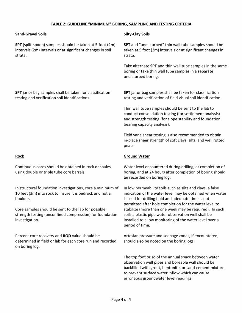
Page 4 of 4
TABLE 2: GUIDELINE “MINIMUM” BORING, SAMPLING AND TESTING CRITERIA
Sand‐Gravel Soils Silty‐Clay Soils SPT (split‐spoon) samples should be taken at 5‐foot (2m) intervals (2m) Intervals or at significant changes in soil strata.
SPT and “undisturbed” thin wall tube samples should be taken at 5 foot (2m) intervals or at significant changes in strata. Take alternate SPT and thin wall tube samples in the same boring or take thin wall tube samples in a separate undisturbed boring.
SPT jar or bag samples shall be taken for classification testing and verification soil identifications.
SPT jar or bag samples shall be taken for classification testing and verification of field visual soil identification.
Thin wall tube samples should be sent to the lab to
conduct consolidation testing (for settlement analysis) and strength testing (for slope stability and foundation bearing capacity analysis).
Field vane shear testing is also recommended to obtain
in‐place sheer strength of soft clays, silts, and well rotted peats.
Rock Ground Water Continuous cores should be obtained in rock or shales using double or triple tube core barrels.
Water level encountered during drilling, at completion of boring, and at 24 hours after completion of boring should be recorded on boring log.
In structural foundation investigations, core a minimum of 10 feet (3m) into rock to insure it is bedrock and not a boulder. Core samples should be sent to the lab for possible strength testing (unconfined compression) for foundation investigation.
In low permeability soils such as silts and clays, a false indication of the water level may be obtained when water is used for drilling fluid and adequate time is not permitted after hole completion for the water level to stabilize (more than one week may be required). In such soils a plastic pipe water observation well shall be installed to allow monitoring of the water level over a period of time.
Percent core recovery and RQD value should be determined in field or lab for each core run and recorded on boring log.
Artesian pressure and seepage zones, if encountered, should also be noted on the boring logs.
The top foot or so of the annual space between water
observation well pipes and boreable wall should be backfilled with grout, bentonite, or sand‐cement mixture to prevent surface water inflow which can cause erroneous groundwater level readings.

Page 1 of 16
STATE OF OKLAHOMA DEPARTMENT OF TRANSPORTATION
GEOTECHNICAL SPECIFICATIONS FOR ROADWAY DESIGN
June 29, 2011
APPENDIX 3. ‐ STANDARD GUIDE FOR THE DESCRIPTION OF SURFACE AND SUBSURFACE GEOLOGICAL ROCK FORMATIONS OF OKLAHOMA
This guide provides standard methods of describing geologic rock formations as required by the
Materials Division of the Oklahoma Department of Transportation (ODOT). These descriptions
shall be of such quality and quantity as to provide complete and accurate rock type information
useful to ODOT.
This guide is to be used to describe various sedimentary and igneous consolidated rock
formations, henceforth called “units,” in the State of Oklahoma. Such units are exposed at the
earth’s surface as well as in borings. These rock units may lie exposed naturally, undisturbed by
man or be present in man‐made cuts, pits, ditches, or similar features. Loose uncompacted
earth materials, such as alluvium, are considered unconsolidated and are not included in this
guide.
In addition, this guide applies to descriptions of rock types as recovered from drill bit cuttings,
or as observed in cores. It is structured such that the description of rock characteristics most
pertinent to the construction or repair of ODOT facilities is emphasized. Other more detailed
terms may be used to describe obvious features of the rock units; i.e. carbonaceous, veins,
mottles, or fissures, but they must be defined in the “Glossary of Geology” (1). The person or
persons using this guide to describe rock types must be a geologist, geological engineer, civil
engineer, or a trained, experienced, qualified individual that has been certified by the ODOT
Materials Division or other approved designated authority.
Geographic locations of the geological log or outcroppings must be described from plans by
Station to the nearest foot and tenth, when such information is available. A minimum of a legal
description accurate to the nearest 100 ft. is required when plans or other detailed location
information is not available. Global Positioning System (GPS) locations are acceptable. All
locations shall be referenced to plan station and offset. Elevations of the ground surface to the
nearest tenth of a foot are required for all borings. As a minimum, all boring logs shall include
the following ancillary information:
1. Stratigraphic location, to nearest 0.1 foot, of any sample(s) or tests taken.
2. Name of contractor
3. Name of logger
4. Core or hole diameter, in inches
5. Boring number
6. Date drilled or logged
7. Bit type
8. Method of drilling

Page 2 of 16
When cores are taken, identify the Rock Quality Designation (RQD) according ASTM D 6032.
For continuous core sampling, use the Rock Mass Ratings (Geomechanics Classification)
procedure identified in ASTM D 5878. The following is a list of the rock characterization
elements to be used in describing the rock units. The elements describing the character of rock
types are to be presented in the report in the order listed.
1. Rock Type (Lithology)
2. Color
3. Thickness
4. Gradation
5. Texture
6. Pores
7. Cementation
8. Hardness
9. Layering (or bedding)
10. Joints
Not all of the above elements will be present at a given site. The type of construction being
considered, the character of the rock encountered, and the method of investigation are
examples of situations that will dictate the elements used to describe the rock (unit(s) in the
report.
Types and Descriptions of Rock
The term lithology pertains to the rock type being observed and described. The following rock
descriptions represent the rock types or lithologies commonly found in Oklahoma. They occur
as outcroppings or as recovered in cores. These example descriptions are to be included in the
Geotechnical Report. The most common rock types are listed first.
1. Shale. Shales are fine grained sedimentary rocks consisting of compacted and hardened
clay, silt or a combination of the two particle sizes. Shales normally contain at least 67%
clay, with the remainder being silt with a chemical or crystalline material acting as a
cementing agent. Shales are by far the most common of the sedimentary rocks. They
are usually identified in the field by their laminated or fissile appearance. Shales can be
any color. They are usually gray, brown, olive, or black in the eastern half of Oklahoma
and shades of red often with greenish‐gray spots or layers in western Oklahoma. The
reddish shales of western Oklahoma commonly do not exhibit strong laminations but
are more massive or blocky in appearance. They usually exhibit a smooth, sometimes
waxy feel.
2. Sandstone. Sandstones are medium grained, consolidated, sedimentary rocks
composed primarily of 85‐90% quartz grains and 10‐15% of a cementing agent such as

Page 3 of 16
calcium carbonate which will fizz upon the application of a hydrochloric acid solution
(HCL, 1 part concentrated hydrochloric acid in three parts distilled water) or more
commonly, silica. The cementing medium commonly contains minor amounts of silt
and/or clay. The quartz grains are sand sized and can be seen with the naked eye.
Sandstones are commonly reddish in western Oklahoma. In eastern Oklahoma,
sandstone is most commonly brown to yellowish but many are gray. They usually
exhibit a gritty feel.
3. Limestone. Limestones are sedimentary rocks consisting of more than 95% of the
mineral calcite (calcium carbonate). The remaining 5% is commonly dolomite. They
occur in beds or layers. They may contain minor amounts of chert (silica), clay, pyrite,
feldspar, and siderite. They will fizz upon the application of a hydrochloric acid solution.
They may be massive or contain visible fossils. They may increase in fossil content to
the point of being composed entirely of fossil shells of various types and sizes. These
are common in southeastern Oklahoma. Limestones are most commonly whitish or
cream in color but range through brown and red, to black. Limestones are commonly
hard but may be soft and chalky.
4. Gypsum. Gypsum is a rock composed of the mineral gypsum, which is hydrous calcium
sulfate. Gypsum occurs as massive layers or beds. It normally does not contain any
particles of sand, silt, or clay. It is white in color and may occasionally contain streaks of
reddish brown. Gypsum is softer than limestone and will not fizz upon the application
of a hydrochloric acid solution. Gypsum is found in the western half of Oklahoma.
5. Anhydrite. Anhydrite is a rock similar to gypsum. It occurs in beds or layers. It is
composed of calcium sulfate without the water of hydration, which is present in
gypsum. Anhydrite is slightly harder than gypsum but still a soft rock. Anyhydrite
generally has the same appearance as gypsum and occurs associated with gypsum in
western Oklahoma.
6. Siltstone. Siltstones are consolidated sedimentary rocks that contain at least 70% silt
sized particles with the remainder being clay size particles. They can be any color. They
usually appear flaggy to thin bedded but are not as fissile as shales. Siltstones are
usually soft but may occasionally be hard.
7. Conglomerate. Conglomerates are consolidated sedimentary rocks that contain
rounded to subangular fragments larger than sand size (2mm). They appear to be a
“gravelstone”. Often the particles range up to small boulder (12 inch) size. The
particles are usually rounded to subrounded. The matrix is commonly silt and sand

Page 4 of 16
cemented by calcium carbonate (which will fizz upon the application of a hydrochloric
acid solution), iron oxide, silica, or clay. Conglomerates are usually brownish to reddish
in color. They are usually found in massive beds and associated with sandstones.
Conglomerates are usually hard but range from soft to hard. They are named by the
composition of the “gravel” fragments. For example, if the gravel‐sized material is
mostly limestone, the rock is described as a limestone conglomerate.
8. Dolomite. Dolomite is a sedimentary rock that contains more than 50% of the mineral
dolomite, which is a calcium/magnesium carbonate, CaMg(CO3). Dolomite commonly
contains more than 90% dolomite with the remaining percentage being calcite. It will
not fizz upon the application of a hydrochloric acid solution. However, it will fizz if
powdered (e.g. with knife scratches or similar techniques). Dolomite commonly occurs
with limestones or interlayered with limestones. Most Oklahoma dolomite is white,
ranging to light gray or sometimes slightly pinkish. Dolomite is commonly hard, durable
rock. Dolomite occurs in all areas of Oklahoma except the panhandle.
9. Caliche. Caliche is a rock‐like soil deposit of the high plains of northwestern Oklahoma.
It is calcareous and will fizz upon the application of a hydrochloric acid solution. It may
contain various amounts of gravel, sand, silt, and clay locally. Caliche occurs as a 2 to 3
ft thick bed or layer at or near the soil surface. Sometimes the caliche is degraded and
soft, being easily dug with a knife. Caliche is usually whitish or light gray.
10. Granite. Granite is an igneous rock (not bedded) that is hard, dense and crystalline. The rock is composed of crystals of quarts, feldspar, and a minor amount of dark minerals.
Feldspar gives granite its color. Colors range from salmon in the Wichita Mountains of
southwestern Oklahoma, light reddish purple in the Tishomingo area, to grayish in the
Arbuckles. Weathered granite is usually whitish and soft.
11. Gabbro, Anorthosite, Prophyry, and Basalt. These rocks are igneous and similar in
physical properties and mode of occurrence to granite. These are all hard dense rocks
that are not bedded, except basalt, which appears as a lava flow atop Black Mesa in the
extreme northwestern tip of Cimarron County in the panhandle. The other rocks occur
in association with granite. Gabbros are hard, dark to black colored rocks occurring in
masses or veins. Anorthosites are composed primarily of feldspar. In Oklahoma They
are hard, dark grayish and also occur in masses or veins. Porphyry is a hard, coarsely
crystalline rock with the same mineral content as granite or any other igneous rock.
12. Chert. Chert (sometimes called flint) is a very hard, dense, siliceous sedimentary rock.
Chert consists of interlocking invisible microcrystalline or cryptocrystalline quartz

Page 5 of 16
crystals of less than 30 µm. Chert has a splintery fracture. It commonly occurs as
nodules or concretions in limestones. Chert only occasionally occurs in beds. It will not
fizz upon the application of a hydrochloric acid solution. This is commonly medium to
dark gray but due to impurities, may be brown, black, reddish, or whitish. Chert is more
commonly found in northeastern Oklahoma.
These rock types are not always pure. For example: Sandstones may contain more than just sand grains. If it contains a calcareous matrix or cementing agent, then it should be called limy or calcareous sandstone. If limestone is composed mostly of whole or broken fossils, it should be described as a fossiliferous, etc.
Descriptions for the rock types should be based on the following:
1. Color: Describe the color using Munsell rock color chart notations and symbols
2. Thickness: Record the thickness of each rock type either in an outcropping or in a log
should to the nearest 0.1 foot. The elevation in feet and nearest tenth is required on all
logs or other appropriate or designated reports.
3. Texture: The term texture refers to the arrangement of grains, particles, or crystals on a
freshly exposed rock surface, as easily seen by the naked eye. Texture indicates the
appearance as megascopic or microscopic as seen on the surface of mineral aggregate.
The following describes the texture of geometrical aspects of the rock grains.
a. Grain Size: There are two major grain size classes:
Coarse grained. This texture is one in which the large crystals or grains can be seen easily by the naked eye.
Fine grained. This texture is one whose grains cannot be seen without magnification.
b. Grain Shape: There are six grain shape classes: Very angular Angular Subangular Subrounded Rounded Very rounded
c. Grain Arrangement: From a morphological standpoint, rock texture is grouped
into three main groups. Homogenous Nonhomogeneous (or Hetrogeneous) Layered

Page 6 of 16
For example: a rock may be described as, “coarse grained, subrounded, homogeneous, etc.”
4. Cementation: Cementation is a term used to describe the natural cementing agents
surrounding the grains and binding the grains together making a rigid and compact
mass. They may include the following:
a. Siliceous: A granular rock with the mass cemented by silica. It is hard and cannot be scratched by a knife blade. It will not fizz upon the application of a hydrochloric acid solution. It is usually shades of gray but may be any color.
b. Calcareous: A rock with calcareous or limy cement. It is not as hard as the siliceous cement. It ranges from fairly hard to soft. It will fizz upon the application of a hydrochloric acid solution. It is usually whitish but may be any color.
c. Ferruginous: A rock cemented by iron. It is usually hard to very hard. It is dark red in color; sometimes it will show yellowish streaks or pockets.
d. Argillaceous: A rock cemented by clay. It is usually soft and can be any color.
5. Hardness: The rock hardness* classes most pertinent to engineering are as follows:
a. Soft: The rock can be worked with a shovel, friable, can be broken by hand in a
dry to moist hand specimen, easily carved with a knife when moist. The red clay
shales and mudstones of western Oklahoma are usually soft.
b. Moderately Hard: The rock cannot be worked with a shovel. It can be worked
with a geology hammer, or pick. It can be scratched with a penny. Examples of
such rocks are the gypsums, anhydrites, and caliches of western Oklahoma.
Many sandstones and siltstones are among this class, as well as some black
shales in the Quachita Mountains of southeastern Oklahoma.
c. Hard: The rock cannot be worked with a pick. It has a ring when struck with a
hammer. It cannot be scratched with a penny but can with a knife. Most
competent rocks are within this category. Most limestones, sandstones, and
dolomites are examples.
d. Very Hard: The rock has a distinct ring when struck with a hammer. Cannot be
scratched with a knife. Examples include the siliceous limestones of eastern
Oklahoma and the granites and other igneous rocks of the Witchitas and
Arbuckles.
*These are hammer tests. They should be made with a 2 lb hammer on a 4 inch or so
diameter specimen lying on a flat hard surface. Friable hand specimens should also be

Page 7 of 16
about 4 inches. The hammer soundness test on rock outcrops should be on layers at
least 1 ft thick.
6. Layering: Most of the rocks of Oklahoma occur as beds or layers. The exceptions are
the granites and other ingenious rocks of the Wichitas and Arbuckles. Include a
description of the character of the beds or layers from the list below in the Geotechnical
report.
a. Fissile: Splits easily along closely spaced plains of 1/16 inch or less. Many shales
of eastern Oklahoma are fissile.
b. Very Thin Bedded: Beds of 1/16 to 2 in. (known as stringers)
c. Thin Bedded: Beds of 2 inches to 2 feet.
d. Thick Bedded: Beds of 2 to 4 feet. Beds in excess of 4 feet are described as “very
thick bedded”.
e. Massive Bedded: Beds exceeding 4 feet. Usually describes homogeneous beds
that have little or no evidence of minor joints, laminations, or imperfections.
Gypsums are commonly massive bedded.
7. Joints, Faults, and fractures: A Joint is defined as a surface of a fracture or a
discontinuity in a rock mass, without displacement (faulting). If displacement of the
sides of the rock, relative to one another, can be observed along the discontinuities,
then the feature is by definition a fault. Sedimentary rocks will usually have two sets of
parallel joints. All the features defined above are considered discontinuities within a
rock mass. Note: Unusual conditions where rocks are observed exhibiting closely
spaced (measured in inches or fractions thereof) joints and faults may be described as
fractured or highly fractured. Their rating classes are as follows:
a. Very Low Jointing. A distance of more than 6.5 ft between discontinuities.
b. Low Jointing. A distance 2.0 to 6.5 feet between discontinuities.
c. Medium Jointing. A distance of 8 inches to 2.0 feet between discontinuities.
d. High Jointing. A distance of 2.5 to 8 inches between discontinuities.
e. Very High Jointing. A distance of less than 2.5 inches between discontinuities.

Page 8 of 16
8. Pores: The open spaces in a rock or soil. Pores are to be observed with the unaided
eye. Measure, describe, and report where there are obvious features in a hand
specimen or length of core. Use the following class sizes:
a. Very Fine. Less than 1.0 mm. b. Fine. 1 to 2 mm c. Medium. 2 to 5 mm d. Coarse. 5 to 10 mm* e. Very Coarse. More than 10 mm* f. Vugs. 5 to 30 mm
*If irregular shaped coarse and very coarse pores are present in limestones, dolomites, or gypsums, they may be described as having vugs or vuggy (small cavity in a rock).
References: a. Jackson, J.A. “Glossary of Geology,” America Geological Institute, Fourth
Edition, 1997.
b. Geological Society of America, “Rock Color Chart, Munsell,” 8th Printing, 1995.
c. Jumikis, A.R., “Rock Mechanics,” Second Edition, Trans. Tech Publs., Federal
Republic of Germany, 1983.
d. Compton, R.R. “Geology in the Field,” John Wiley and Sons, 1985.
e. American Association of State Highway and Transportation Officials, “Particle
Size Analysis of Soils,” T‐88, 1999.
f. “Standard Field Descriptions of Sedimentary Rocks,” Research Section,
Materials Division “ 1961
g. Schoeneberger, P.J. et al., “Field Book for Describing and Sampling Soils,”
Version 1.1, USDA, NRCS, Lincoln NE, 1998.
Other Relevant Publications:
“Engineering Classification of Geologic Materials,” Vols. 1‐8 Research and Development Div.,
ODOT, Curtis Hayes, Principal Investigator, 1965 to 1972.

Page 9 of 16
EXAMPLES
The features listed in the above Guide are to be noted in the report or log as observed in cuttings, cores, and outcroppings. The most current versions of Rock Quality Designations (ASTM D6032), Rock Mass Ratings (ASTM D5868), and Diamond Core Drilling for Site Investigation (ASTM D2113) are to be used. When coring, NX Core sizes are preferred; a minimum of NQ is required.
The following is an example of core log from a bridge boring:
Surface Elevation __________ ft Station __________ + _________, feet left or right
0.0 – 3.3 Fine sand (2.5 Y8/6), alluvium, not covered 3.3 – 13.5 Shale – Red (10R5/8), sandy, mottled with yellow (5Y8/6), soft, fissile 13.5 – 15.5 Siltstone – Gray (10YR3/1), mod. Hard, thin bedded. 15.5 – 23.0 Sandston – Red (10R6/6), mottled with yellow (5Y7/8), mostly fine ranging to
coarse grains, becoming coarser with depth, med graded, mod. hard, massive, calcareous, many fine pores.
23.0 – 23.7 Limestone Conglomerate – Reddish – brown (5YR5/4), limestones are light
gray (10YR7/1), mod. hard, particle sizes range from clayey matrix up to about 4 in gravel, well graded, calcareous cement, few coarse pores, thin bedded.
23.7 – 30.1 Limestone – Gray (10YR7/1), hard, thick bedded, contains two thin zones (1/2
in) of broken fossil shells at 28.6 and 29.1 30.1 – 33.6 Dolomite – Pinkish gray (5YR6/2), sandy, hard, thin bedded, occasional, large
pores, vuggy 33.6 – 39.3 Interbedded dolomite and shale – Dolomite; pinkish gray (5YR6/2), shale; very
dark gray (5YR3/1), dolomite is thin bedded, hard; shales range from thin to thick bedded, minor small pyrite, mod. hard, becomes predominantly shale @ 37.0
39.3 TD, shale – very dark gray, (5YR3/1), as described above.
Logged by: Bit Type, Size, Design: Date of Start, Finish: Contractor: Ground Water Level,
Dates: Other ASTM 2113 Boring Items as Appropriate
Hole Diameter (core):
Project Identification:

Page 10 of 16
The following is an example of a description of an outcropping along a proposed roadway alignment:
Station 139 + 50, from centerline 12 ft right.
Layer Thickness (ft.) Description
1 0 – 10.3 Sandstone, brown (10YR5/3), fine, poorly graded, moderately hard, mostly thin bedded, high jointing; one thick bed at 5.3 to 7.8 ft. Sandstone contains thin stingers of brown sandy shale near the base and grades to
2 10.3 ‐ 15.5 Interbedded sandstone and sandy shale, brown (10YR5/3), mostly soft ranging to mod. hard, very thin bedded ranging to thin bedded, high jointing, becoming more shale‐like at the base.
3 15.5‐26.6 Shale, very dark grayish brown (10YR3/2), soft fissile, contains veins of reddish yellow (7.5YR6/8) going at all angles.
4 26.6 Elev. Of roadway grade

Page 11 of 16
Seismic Velocity Charts
for Estimating the
Rippability of Various
Soil and Rock Formations

Page 12 of 16
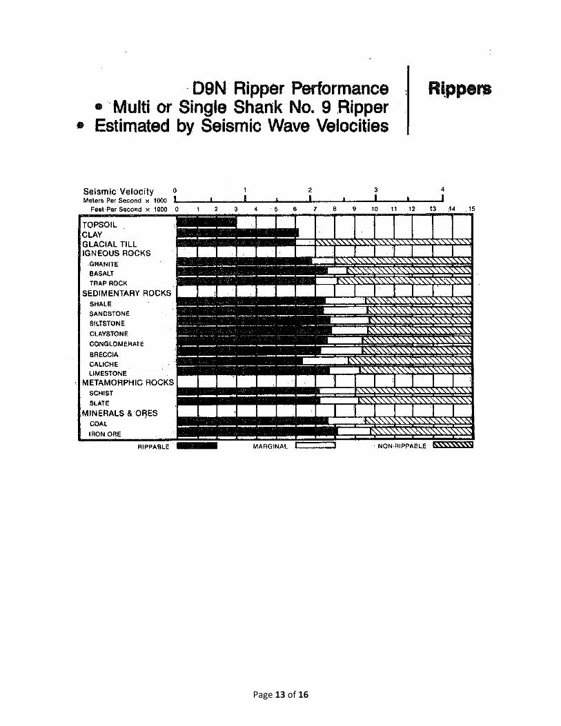
Page 13 of 16

Page 14 of 16

Page 15 of 16

Page 16 of 16

Page 1 of 12
STATE OF OKLAHOMA DEPARTMENT OF TRANSPORTATION
GEOTECHNICAL SPECIFICATIONS FOR ROADWAY DESIGN
JUNE 29, 2011
APPENDIX 4. ‐ GUIDE FOR PREPARING GEOTECHNICAL REPORTS This purpose of this guide is to provide clear and concise methods for preparing geotechnical reports for the Oklahoma Department of Transportation. When used as described, this information will provide consistent and appropriately documented geotechnical reports. Overview
Geotechnical reports provide written documentation of findings from preliminary
investigations, field explorations, laboratory testing, geotechnical evaluations and construction
planning reviews. The Geotechnical Engineer responsible for the report should have broad
experience in geotechnical engineering and a background in engineering for the type of
roadway work identified in the project. The project geotechnical specialist, responsible for the
report preparation, should have a broad background in civil engineering with a good basic
knowledge of the soils and geology of Oklahoma as well as an understanding of the designs that
are required to remedy the problems at a certain specific location(s). The project geotechnical
specialist should anticipate possible design and construction issues and provide
recommendations and solutions to mitigate or eliminate problems as well as any comments
concerning possible limitations or other construction problems. The recommendations should
be brief, concise and include the reasons for the recommendations. Provide any supporting
data (e.g., graphics, tabular data, and calculations) in the appendices of the report.
Supplemental Geotechnical Report
Occasionally, the project design team may request the Geotechnical Engineer to conduct
additional geotechnical reviews or studies. Based on these reviews or studies, the project
geotechnical specialist will prepare a supplemental report to the geotechnical report. The
supplemental report should only address the analysis and alternatives for those elements
requested for additional geotechnical review or study.
Special Reports
Occasionally, the project geotechnical specialist may be required to prepare a special
geotechnical report not related to a particular project (e.g., landslides, rock falls). Typically,
these reports are prepared under emergency conditions and, as a result, only include
recommendations to mitigate immediate problems. The special report should include the
methods of analysis, calculations, design assumptions, computer programs used and other
information as applicable to arrive at the design recommendations.

Page 2 of 12
Geotechnical Reports
The Final Geotechnical Report for Roadway Design should contain all the geotechnical data and
recommendations required for design. The report should be organized to include Transmittal
Information about the report, General Information about the project, Field Investigation and
Laboratory Testing Information, and the Geotechnical Information required for Roadway Design
projects. These are described in greater detail in succeeding sections of this appendix. In
addition to this required information, the final geotechnical report should include the following,
where applicable:
design geotechnical data;
design computations as required by the consultant’s agreement;
quality assurance/quality control certifications including lab and technician certification;
and
any alternative designs considered.
The Geotechnical Engineer is required to conduct a quality assurance review of the report
before it is submitted to ODOT. The quality assurance review should include checking all
calculations, as well as a review by a senior engineer or geologists of the approach,
assumptions, results and conclusions/recommendations of any work carried out for the project.
The report should also be edited to be free of grammatical and spelling errors, and graphics
should be legible and easy to interpret. Geotechnical reports must be dated, signed, and sealed
by a Professional Engineer licensed in the State of Oklahoma.
The Geotechnical Engineer shall submit the final geotechnical report to ODOT in two hard
copies and one PDF copy on CD.
The Department, upon review of the final written report and boring logs, will exercise final
authority as to whether the consultant has provided sufficient information or if additional data
or borings are required. The Department further reserves the right to review all phases of the
geotechnical report, including all field and laboratory data, computations and analysis.
GEOTECHNICAL EVALUATION REPORT
In general, organize all geotechnical project reports using the following format.
Transmittal Information
The project geotechnical specialist should use the following format when preparing the
transmittal memorandum for the geotechnical report:

Page 3 of 12
1. Addressee (To): Address the memorandum to the ODOT Division Engineer (e.g.,
Roadway Design Division, Bridge Division, Field Division) responsible for the project
oversight.
2. Contact. Provide the name, telephone number and email of the individual(s) that can be
contacted for additional information or questions.
3. Signature (From): Prepare the report for the Geotechnical Engineer’s signature. Also,
include the report author and title directly underneath the author’s signature line.
4. Date. Include the date the report is submitted to the addressee.
5. Subject. In the subject, include the official construction project number, job piece
number, and project description.
General Project Information
The project geotechnical specialist is responsible for preparing a detailed geotechnical
engineering report outlining the findings of the field and laboratory investigations and, where
applicable, results from the geotechnical engineering analyses, designs for geotechnical
features and recommendations and alternatives for potential issues affecting the project
alignment or construction.
Not all of the subject areas listed in the following Sections will be required for every
geotechnical report and adjustments may be required as deemed necessary. The level of
coverage for each item will also vary from project‐to‐project. Although in‐depth coverage of
individual details is usually not provided in the report, provide sufficient detail to allow the
reader to fully understand the problem and any proposed recommendations. Detailed analyses
may be added as appendices to the report.
The following provides the topic areas, listed in order, to be addressed in geotechnical reports:
1. Introduction. Identify the purpose of the report and provide a very brief summary of
what is included in the report.
2. Project Information. Include the following in the project description:
construction project number and job piece number;
the county where the project is located;
route number or street name;
nearby towns and/or cities;

Page 4 of 12
the project location with respect to the highway mileage markers and/or project
length;
general scope of the project (e.g., roadway reconstruction, pavement widening
and/or overlay);
major features of the project (e.g., four‐span structure, retaining wall, final
roadway widths, design speed); and
other applicable elements of the project (e.g., deep cuts or fills, special drainage
considerations, detour requirements).
3. Area Geology. Note the topography of the project area. Identify the soil and rock type
formations within the project area. Note the predominate soil and rock types that can
be found within the project area. If available, provide a description of the soil and rock
formations (e.g., expansive soils, dispersive clay, karst).
4. Site Reconnaissance. Note any geotechnical features found during the investigation,
including, but not limited to, the following:
outcrops of bedrock;
existing cuts and fills, including slope angles;
evidence of current or past landslides;
surface soils;
potential problem soils such as dispersive or expansive clays sulfate bearing soils;
groundwater conditions (e.g., springs, streams, irrigation);
wetland locations;
areas that may require subexcavation or other foundation stabilization/drainage
measures;
locations that may require rock excavations, including areas that may require
blasting;
locations that will require extensive excavations and/or fills;
roadway patching that may indicate subgrade problems;
the type of vegetation or lack thereof;
location of nearby buildings, drainage structures, bridges, utilities, etc.; and
other features that may affect the project alignment, right‐of‐way and/or design.
5. Subsurface Investigation. Document the insitu tests conducted and their results.
Provide the preliminary soil classifications determined from the subsurface
investigation. Indicate any special considerations required for the subsurface
investigation (e.g., location of utility lines, steep terrain, nearby structures, wetlands,
private property, and required permits). Include the proposed scope of the field and
laboratory work that appears to be necessary for future phases of the project.

Page 5 of 12
6. Design and Construction Recommendations. Where applicable, provide design and
construction recommendations to the project designer so that it can be considered
during the design phase. Include the information noted in Sections 3.2.4 and 3.2.5, as
applicable.
7. Report Limitations. Provide possible constraints so they may be considered during the
preliminary stage of design.
Field Investigation and Labortory Testing Information
Geotechnical investigation and testing information is a vital part of geotechnical reports. The
information in geotechnical reports should provide written documentation of findings from the
field explorations and laboratory testing. Where applicable, the project geotechnical specialist
should include the following information in the geotechnical report:
1. Pedological Investigation. The pedological investigation should include and consist of
the following elements:
Include aerial photographs at 1:20,000 scale (or the scale that is used by NRCS in
their county soil survey reports) with delineated map units and proposed
location or center reference line/centerline alignment plotted thereon
(reproduction from county soil survey report) are required. Obtain copies of
Digital Orthophoto Quad sheets from the Oklahoma Conservation Commission
website.
Sum and report the traversed distance of each alphabetized map unit in feet.
Include a set of official soil series description sheets from the official NRCS
national database source (Iowa State). These are for the soil series found along
the alignment extent or at the location of interest.
Provide a numerical listing in alphabetical order of the soil series found along the
alignment along with their Taxonomic classification (e.g., Burleson Soil Series,
Fine, smectitic, thermic, Udic Haplustert).
Include field logs of the soil samples taken from all soil horizons for each soil
series. Describe the results according to the official soil series description. Also,
a large composite sample of the major horizons, excluding the A horizon, are to
be listed.
As an option to using county soil survey maps, the soil map units may be plotted
on digital orthophoto quad sheets. These are at 1:24,000 scale and are

Page 6 of 12
appropriate for the report. These can be obtained at the State of Oklahoma
Conservation Commission.
Provide a list of the required laboratory tests conducted and the findings from
these tests. Standard forms for reporting Pedological Investigation information
are provided in Appendix 5.
2. Shoulder Survey/In Place Soils Investigation. The Shoulder/In Place soils investigation
should include the following information:
Field logs of the soil samples taken with depths and station extents of similar soil
types within the project extents. Note on the logs which soils samples were used
to conduct resilient modulus tests.
Provide a list of the required laboratory tests conducted and the findings from
these tests. Standard forms for reporting Shoulder Soils/In Place Soils
Investigation information are provided in Appendix 5.
3. Pavement and Subgrade Soils Investigation. The Pavement and Subgrade Soils
Investigation should include the following information:
Back calculated FWD data of the pavement section in tabular format. Include a
CD with the back calculated data in Excel format for further analysis.
Detailed core logs with color photo of core. Note the pavement layer thicknesses
and condition.
Pavement surface condition survey as detailed in FHWA‐RD‐03‐031
Field logs of the soil samples taken with depths and station extents of similar soil
types within the project extents. Note on the logs which soils samples were used
to conduct resilient modulus tests.
Provide a list of the required laboratory tests conducted and the findings from
these tests. Standard forms for reporting Pavement and Subgrade Soils
Investigation information are provided in Appendix 5.
4. Subsurface Investigation. When summarizing the subsurface investigation include the
following information, where applicable:
permission from property owners;
number of borings taken and dates that the boring work took place;
summary of the soil and rock types found;

Page 7 of 12
general description of the land formation (e.g., gullies, excavations, slopes,
stream banks) and vegetation;
study of existing structures;
location of underground and overhead utilities:
presence of surface water and stream debris;
subsurface water table and location on the boring logs;
unusual drilling conditions;
any additional subsurface testing that was conducted (e.g., groundwater
monitoring, seismic), the equipment used, the stationing and other applicable
information relative to the test;
results of the in‐situ tests (e.g., SPT, CPT);
boring logs, maps indicating the boring locations, including the plan station and
offset, data from site tests, etc., in the appendices; and
location for material and borrow sources.
5. Laboratory Testing. Indicate the laboratory tests that were completed on the soil and
rock samples. Include a summary of the laboratory testing results. Discuss the results
of these laboratory tests.
6. Soil Classification. Identify soil classifications in sufficient detail to permit engineers to
recognize features significant to design and, if need be, to obtain samples in the field.
7. Geological Surface and Subsurface Rock Formation Information. Geological rock
formation information should be provided using the standard methods of rock type
descriptions as described in Appendix 3. Provide complete and accurate rock type
information useful to designer. In addition, include the descriptions of rock types as
recovered from drill bit cuttings or as observed in cores. The geological information
provided should be structured so that the description of rock characteristics more
pertinent to the construction or repair of ODOT facilities is emphasized.
Where cores are taken, provide the Rock Quality Designation (RQD) in accordance with
ASTM D 6032. If Rock Mass Ratings (Geomechanics Classification) are required note
these according to ASTM D 5878. The following is a listing of the rock characterization
elements to be used in describing the rock units. The elements describing the character
of Oklahoma rock types are to be presented in the report in the order listed:

Page 8 of 12
rock type (lithology),
color,
thickness,
gradation,
texture,
pores,
cementation,
hardness,
layering (or bedding), and
joints.
Not all of the above elements will be present at a given site. The type of construction
being considered, the character of the rock encountered, and the method of
investigation are examples of situations that will dictate the elements used to describe
the rock unit(s) in the report.
An example of the type of report is found in Appendix 3 “Standard Guide for the
Description of Surface and SubSurface Geological Rock Formations of Oklahoma".
8. Plans and Boring Logs. Geographic locations of the geological log or outcroppings must
be described from plans by Station to the nearest tenth of a foot, where the information
is available. A minimum of a legal description accurate to the nearest 100 ft is required
when plans or other detailed location information is not available. Global Positioning
Systems (GPS) locations are acceptable; however, bore hole locations must be
referenced to the plan station and offset. Elevations of the ground surface to the
nearest tenth of a foot are required for all borings. At a minimum, include the following
ancillary information on the logs:
construction project number and job piece number;
stratigraphic location, to nearest 0.1 ft, of any samples or tests taken;
name of contractor;
name of the driller
name of logger;
core or hole diameter, in inches;
boring number;
date the drilling or logging was performed;
type of equipment used (e.g., bit type used);
name of engineer and/or geologist, onsite, responsible for the field boring
logs and interpretation of the geologic profile; and
method (or combination) of drilling used.
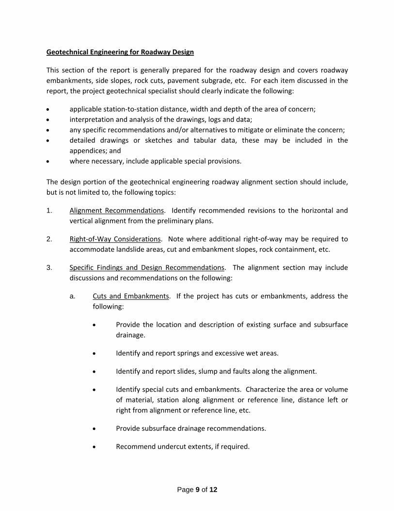
Page 9 of 12
Geotechnical Engineering for Roadway Design
This section of the report is generally prepared for the roadway design and covers roadway
embankments, side slopes, rock cuts, pavement subgrade, etc. For each item discussed in the
report, the project geotechnical specialist should clearly indicate the following:
applicable station‐to‐station distance, width and depth of the area of concern;
interpretation and analysis of the drawings, logs and data;
any specific recommendations and/or alternatives to mitigate or eliminate the concern;
detailed drawings or sketches and tabular data, these may be included in the
appendices; and
where necessary, include applicable special provisions.
The design portion of the geotechnical engineering roadway alignment section should include,
but is not limited to, the following topics:
1. Alignment Recommendations. Identify recommended revisions to the horizontal and
vertical alignment from the preliminary plans.
2. Right‐of‐Way Considerations. Note where additional right‐of‐way may be required to
accommodate landslide areas, cut and embankment slopes, rock containment, etc.
3. Specific Findings and Design Recommendations. The alignment section may include
discussions and recommendations on the following:
a. Cuts and Embankments. If the project has cuts or embankments, address the
following:
Provide the location and description of existing surface and subsurface
drainage.
Identify and report springs and excessive wet areas.
Identify and report slides, slump and faults along the alignment.
Identify special cuts and embankments. Characterize the area or volume
of material, station along alignment or reference line, distance left or
right from alignment or reference line, etc.
Provide subsurface drainage recommendations.
Recommend undercut extents, if required.

Page 10 of 12
Identify unusual erosion control measures that may be necessary.
Provide recommended limits on cut and fill slopes.
Provide shrink‐swell factors for earthwork calculations.
Provide the parameters that characterize the discontinuity and rock
mass, excavation, slopes, blasting requirements, containment areas, etc.
Identify recommended rock extents that are rippable and areas that will
need to be blasted.
Provide recommended rock slope stabilization measures.
b. Soft Ground. If the embankment is over soft ground, provide the following:
Include recommendations for alternative embankment designs if
problematic soils (e.g., dispersive clays, silt) are anticipated from local
embankment borrow sources.
Provide the estimated short and long‐term settlement.
Provide alternative designs, conceptual construction sequencing, time
needs, and address long‐term settlement, including surcharging and/or
wick drains where applicable, and slope stability. Identify methods of
analysis, factors of safety, design codes with version, etc.
Provide recommendations and specifications for monitoring settlement
and slope stability.
c. Floodplains. If the embankment is in a floodplain, provide the following:
Give recommendations for alternative embankment designs if
problematic soils (i.e., dispersive clays, silty soils) are anticipated using
local borrow sources.
Include recommended special provisions for the embankment.
Identify recommended embankment protection for hydraulic impacts on
the embankment including rapid draw down, scour, wave action, etc.
d. Landslides. For landslides, address the following:
Include landslide movement history, past maintenance works, previous
correction measures, etc.

Page 11 of 12
Provide scaled cross‐section showing ground surface conditions before
and after failure.
Identify failure planes, excavation/buttressing limits, recommended
slopes, instrumentation requirements, results from the slope stability
analysis, and drainage requirements.
Summarize causes of the slide.
Provide alternative designs and benefits/limitations of each design.
Provide construction sequence and special provisions.
e. Retaining Walls. Provide internal wall stability design parameters and global
retaining wall stability analysis.
f. Drainage. Discuss excavation concerns, erosion protection, culvert bedding
materials, geotextile fabrics, water table levels, dewatering recommendations
and settlement considerations.
g. Stability Analysis. Address the methods used (e.g., computer programs),
assumptions made for soil strength parameters (e.g., strength), groundwater
conditions, selected factors of safety or resistance factors, conclusions from
analyses (slope angles and heights), and recommended methods of mitigation
(e.g., regrading, reaction berms, ground improvement).
h. Settlement Analysis. Discuss methods used to calculate the settlement analysis,
assumptions for soil parameters (e.g., preconsolidation pressure, compression
index, recompression index, coefficient of consolidation), groundwater
conditions, conclusions from analyses, recommended mitigation. (e.g., dig outs
and subexcavation, use of light‐weight fills, wick drains and preloading, staged
construction).
i. Computer Programs. Include a summary of the analyses and list of software
programs used.
j. Results. Describe the limitations of the analyses and results.
k. Special Issues. Identify special issues to consider during construction, including
construction staging, scheduling of preloads, special field testing and
instrumentation.

Page 12 of 12
Appendices
If available, include the following in the appendix of the report:
1. Maps. If deemed appropriate, include geological or highway maps and indicate the
applicable geotechnical features on the maps.
2. Boring Logs. If boring logs are available from previous projects in the area and they are
applicable to the project, include copies of these logs.
3. Photographs. If photographs were taken during the site investigation, include
applicable photographs showing only the major geotechnical features. On the
photograph, indicate the reason for the photograph (e.g., steep rock cuts, landslides),
the location (e.g., reference post, stationing) and direction the picture was taken.
4. Design Calculations. Include the detail design calculations and results used in making
the analyses and recommendations.
REFERENCES
1. State of Oklahoma Department of Transportation Geotechnical for Roadway Design,
Appendix A3, June 11, 2001.
2. State of Oklahoma Department of Transportation Standard Guide for the Description of
Surface and Subsurface Geological Rock Formation of Oklahoma, Attachment 1 to
Appendix A1 and Appendix A3, June 5, 2001.
3. State of Oklahoma Department of Transportation Guidelines and Background
Information for Providing Soil Classification Information, Attachment 2 to Appendix A3,
June 12, 2001.
4. State of Oklahoma Department of Transportation Specifications for Geotechnical
Investigation of Bridge and Related Structures, Appendix A1, June 5, 2001.
5. Subsurface Investigations – Geotechnical Site Characterization, NHI‐01‐031, FHWA.
6. Checklist and Guidelines for Review of Geotechnical Reports and Preliminary Plans and
Specifications, ED‐88‐053, FHWA.
7. Geotechnical Engineering Circular No. 5, Evaluation of Soil and Rock Properties, IF‐02‐
034, FHWA.

STATE OF OKLAHOMA DEPARTMENT OF TRANSPORTATION
GEOTECHNICAL SPECIFICATIONS FOR ROADWAY DESIGN
June 29, 2011
APPENDIX 5. ‐ STANDARD FORMS FOR REPORTING GEOTECHNICAL INFORMATION
In order to insure uniformity in the information submitted to ODOT, certain standard report formats will be required as follows:
1. Pedological & Geological Soils Test Data 2. Resilient Modulus Test Data 3. Resilient Modulus of Subgrade Soil (AASHTO T 307‐99) 4. Shoulder Soils Survey 5. Pavement Core Data and In‐place Soils 6. Pavement Core logs 7. Soil Series Characteristics 8. FWD Report for Flexible Pavement 9. FWD Report for PC Concrete Pavement
While these forms may be re‐created in an electronic format and the general parameters adjusted as necessary, the content and specific presentation of the information must not be modified. In addition to these standard report Formats, ODOT will require the utilization of the following unique software package gINT® in the development and compilation boring log information.

EXAMPLE TYPE OF SURVEY
Surveyed by: __________________ Sheet ______ of ______ ______________________________ Pedological & Geological Soils Survey Project _________________________________ ______________________________ County ____________ Location _____________ Date Surveyed: _________________ _______________________________________
Field No. Soil Group Station Description Depth (in) L.L. P.I.
Percent Passing
OSI pH Resis. (Ω∙Cm)
Soluble Sulfates (mg/kg) 3 in. ¾ in. #4 #10 #40 #200
120+53, 35 ft. rt.
Renfrow Series
1A A‐6(14) ‘A’ Horizon 0 ‐ 9 37 18 100 100 100 100 100 97.6 15 7.82 616 ND
1B A‐6(14) ‘BA’ Horizon 9 ‐ 13 30 16 100 100 100 100 100 94.0 12 5.71 1144 ND
1C A‐7‐6(27) ‘Btss1’ Horizon 13 ‐ 25 46 30 100 100 100 100 100 87.9 21 6.5 1100 ND
1D A‐7‐6(32) ‘Btss2’ Horizon 25 ‐ 40 48 34 100 100 100 100 100 91.3 23 7.76 484 ND
1E A‐7‐6(27) ‘Btss3’ Horizon 40 ‐ 65 44 31 100 100 100 100 100 89.0 20 7.59 224 ND
1F A‐7‐6(27) ‘C’ Horizon 65 ‐ 75 43 30 100 100 100 100 100 90.1 20 7.33 163 ND
Geology‐Clay shale
Mr‐1A
A‐7‐6(21) ‘B’ Composite 9 ‐ 65 41 22 100 100 100 100 100 90.9 17
Mr‐1B
A‐7‐6(27) ‘C’ Composite 65 ‐ 75 43 30 100 100 100 100 100 90.1 20

EXAMPLE TYPE OF SURVEY
Surveyed by: __________________ Sheet ______ of ______ ______________________________ Pedological & Geological Soils Survey Project _________________________________ ______________________________ County ____________ Location _____________ Date Surveyed: _________________ _______________________________________
Field No.
Soil Group Station Description
Depth (in) L.L. P.I.
Percent Passing
OSI pH Resis. (Ω∙Cm)
Soluble Sulfates (mg/kg) 3 in. ¾ in. #4 #10 #40 #200
432+65, 50 ft. rt.
Burford Series
2A A‐6(9) ‘A’ Horizon 0 ‐ 9 34 13 100 100 100 98 96 78.1 12 8.26 5180 ND
2B A‐6(13) ‘Bw’ Horizon 9 – 22 35 16 100 100 100 100 98 84.9 13 8.25 4850 ND
2C A‐6(10) ‘Bk’ Horizon 22 – 32 34 13 100 100 100 99 98 84.4 12 7.51 524 11,500
2D A‐6(12) ‘2BCk’ Horizon 32 – 38 33 15 100 100 100 99 98 86.0 13 7.78 508 10,500
2E A‐6(11) ‘2C’ Horizon 38 ‐ 60 34 16 100 100 99 99 95 78.6 13 7.89 571 2500
2F A‐7‐6(27) Geology‐Clay shale 60+
Mr‐2A A‐6(11) ‘B’ Composite 9 – 38 34 16 100 100 100 100 100 90.9 17
Mr‐2B A‐6(12) ‘C’ Composite 38 ‐ 60 34 16 100 100 99 99 95 78.6 13

Project No. STP‐123C (123), 12345(04) County Mayes County Location US 69 from Choteau to SH 20 EXAMPLE Resilient Modulus Test Data
Laboratory No. 6783 6789 6792
Sample No. 1 2 1 2 1 2
Station 105+05 113+85 127+90
Location 35 ft lt. CL 20 ft rt CL 18 ft rt CL
Depth (inches) 12 – 60
Soil Series Dennis “B” Parsons “B” Bates “B”
Sieve Size Percent Passing Percent Passing Percent Passing
1” / 25.0 mm 100 100 100
No. 4 / 4.75 mm 100 100 100
No. 10 / 2.0 mm 100 100 100
No. 40 / 0.425 mm 99 99 99
No. 200 / 0.075 mm 95.0 85.2 84.6
Liquid Limit 71 36 56
Plasticity Index 49 20 40
Standard Density , PCF 93.0 99.2 102.6
Optimum Moisture, % 24.6 17.7 21.8
AASHTO Class A‐7‐6(52) A‐6 (16) A‐7‐6(35)
Molded Density, PCF 90.1 88.2 97.2 94.9 100 97.4
Molded Moisture Content, % 24.2 26.9 17.1 19.2 21.4 23.5
Est. Compaction Factor – Shrink / 9.6 % Swell 6.2% Swell 1.6 % Swell
Resilient Modulus, PSI See enclosed data and graphs See enclosed data and graphs See enclosed data and graphs
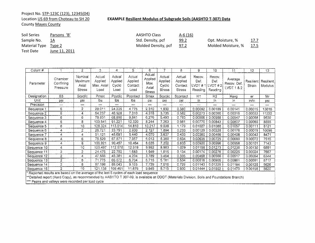
Project No. STP‐123C (123), 12345(04) Location US 69 from Choteau to SH 20 EXAMPLE Resilient Modulus of Subgrade Soils (AASHTO T‐307) Data County Mayes County Soil Series Parsons ‘B’ AASHTO Class A‐6 (16) Sample No. 1A Std. Density, pcf 99.2 Opt. Moisture, % 17.7 Material Type Type 2 Molded Density, pcf 97.2 Molded Moisture, % 17.5 Test Date June 11, 2011


EXAMPLE TYPE OF SURVEY
Surveyed by: __________________ Sheet ______ of ______ ______________________________ Shoulder / In Place Soils Survey Project _________________________________ ______________________________ County ____________ Location _____________ Date Surveyed: _________________ _______________________________________
Field No. Soil Group Station Description
Depth (in) L.L. P.I.
Percent Passing
OSI M.C. %
Soluble Sulfates (mg/kg) 3 in. ¾ in. #4 #10 #40 #200
115+50, 18’RT
1A A‐6(11) Lean Clay 0 ‐ 6 30 13 100 100 100 100 99.4 90.0 15 24.4 ND
1B A‐6(16) Lean Clay 6 ‐ 22 33 19 100 100 100 100 100 92.2 12 24.1 ND
1C A‐6(18) Lean Clay 22 ‐ 36 38 26 100 100 100 100 100 91.5 21 21.8 245
Mr‐1A A‐6(18) Composite‐ Lean Clay 0 ‐ 36 37 26 100 100 100 100 100 92.1 20 24.0 229
120+50, 16’lt
2A A‐6(16) Lean Clay with Sand 0 ‐ 6 36 20 100 100 100 100 97.8 83.5 15 25.9 ND
2B A‐6(20) Lean Clay 6 ‐ 27 30 15 100 100 100 100 100 92.7 12 20.9 125
2C A‐6(13) Lean Clay 27 ‐ 36 35 22 100 100 100 100 100 100 16 26.7 260
Mr‐2A A‐6(16) Composite‐ Lean Clay 9 ‐ 27 33 19 100 100 100 100 99.3 92.2 14 22.6 244

EXAMPLE TYPE OF SURVEY Surveyed by: __________________ Sheet ______ of ______ ______________________________ Shoulder / In Place Soils Survey Project _________________________________ ______________________________ “Same As Approach” County ____________ Location _____________ Date Surveyed: _________________ _______________________________________
Field No. Soil Group Station Description
Depth (in) L.L. P.I.
Percent Passing
OSI M.C. %
Soluble Sulfates (mg/kg) 3 in. ¾ in #4 #10 #40 #200
160+00, 17’ Lt
1A A‐6(11) Lean Clay 0 ‐ 6 30 13 100 100 100 100 99.4 90.0 15 24.4 255
1B A‐6(16) Lean Clay 6 ‐ 30 33 19 100 100 100 100 100 92.2 12 24.1 134
1C A‐6(18) Lean Clay 30 ‐ 36 38 26 100 100 100 100 100 91.5 21 21.8 437
Mr‐1A A‐6(18) Composite‐ Lean Clay 0 ‐ 36 37 26 100 100 100 100 100 92.1 20 24.0 289
165+00, 16’Rt
2A Similar as 1A
2B Similar as 1B
2C Similar as 1C
170+00, 16’ Lt
3A A‐2‐4(0) Silty Sand 0 – 6 NP NP 100 91 83 76 64 26.0 0 12.7 260
3B A‐4(0) Silty Sand 6 – 16 NP NP 100 100 95 88 86 82.9 0 14.5 357
3C Similar as 1C 16 ‐ 36
175+00, 15’ Rt
4A A‐4(0) Silty Sand 0 – 6 NP NP 100 100 91 89 86 81.2 0 14.9 138
4B A‐4(0) Silty Sand 6 – 18 NP NP 100 100 100 100 92 83.2 0 15.1 175
4C A‐4(0) Silty Sand 18 ‐ 36 NP NP 100 100 100 95 88 82.7 0 16.5 211
Mr‐2A A‐4(0) Composite‐ Silty Sand 0 ‐ 36 NP NP 100 100 98 95 90 82.1 0 185
180+00, 16’Lt
5A Similar as 4A 0 – 6
5B Similar as 4A 6 – 12
5C A‐6(16) Lean Clay with Sand 0 ‐ 6 36 20 100 100 100 100 97.8 83.5 15 25.9 244
5D A‐6(20) Lean Clay 6 ‐ 27 30 15 100 100 100 100 100 92.7 12 20.9 311

Project No. STP‐123C(123), 12345(04)
Location US 69 From Choteau to SH 20
County Mayes
EXAMPLE
PAVEMENT CORE DATA & IN‐PLACE SOILS
Soil No. Field No. Soil Group Station CL RT‐LT Description Depth (in) L.L. P.I.
Percent Passing
OSI MC % # 4 # 10 # 40 # 200
86+05 5’ Rt. Type S4 Asphalt 0‐2 Major Stripping
Type S3 Asphalt 2‐5 Minor Stripping
Type S3 Asphalt 5‐8 Minor Stripping
Type S3 Asphalt 8‐11
Aggregate Base 11‐18
7297 1A A‐6(19) Lean Clay with Sand 18‐36 40 23 98 97 95 85.1 17 21.1
87+30 6’ Lt. Type S4 Asphalt 0‐2
Type S3 Asphalt 2‐4,5 Major Stripping
Type S3 Asphalt 4.5‐7.5 Deteriorated
Type S3 Asphalt 7.5‐11
Aggregate Base 11‐18.5
7298 2A A‐2‐6(0) Silty Clayey Gravel with Sand 18.5‐25.5 28 12 56* 42 35 27.5 4 16.8
7299 2B A‐6(11) Lean Clay with Sand 25.5‐36 34 16 99 97 90 77.8 13 20.4
*Maximum Size Passing One Inch Sieve

EXAMPLE ASPHALT CORE LOG

EXAMPLE CONCRETE CORE LOG

Project No. STP‐123C(123), 12345(04)
Location US 69 From Choteau to SH 20
County Mayes
Table 1 Typical Characteristics of Soil Series
Soil Series
Lineal Extent (ft)
Slope Variability
% Parent Material
Depth to Bedrock (in) Drainage Permeability
Shrink‐Swell
Potential CommentsBates 1550 1 ‐ 5 Sandstone 30 ‐ 34 Well Moderate Low to
moderate ‐ moderate corrosion risk to concrete ‐ low strength
Dennis 4320 1 ‐ 3 Shale 60 Mod. Well Slow Moderate to high
‐ high corrosion risk to uncoated steel ‐ moderate corrosion risk to concrete ‐ low strength ‐ perched water table 2‐3 ft Dec.‐ April
Okemah 980 0 ‐ 1 Shale 60 Mod. Well Slow High ‐ high corrosion risk to uncoated steel ‐ moderate corrosion risk to concrete ‐ low strength ‐ perched water table 2‐3 ft Dec.‐ April
Parsons 1340 0 ‐ 1 Shale 60 Poor Very slow High ‐ high corrosion risk to uncoated steel ‐ moderate corrosion risk to concrete ‐ low strength ‐ perched water table 2‐3 ft Dec.‐ April
Verdigris 130 Nearly level Alluvium > 72 ModeratelyWell
Moderate Moderate ‐ subject to flooding

EXAMPLE FWD REPORT FOR FLEXIBLE PAVEMENTProject No. STPY-150B(042)U.S. Highway 177 From Carter/Murray County Line Extending North 5 MilesMurray County, Oklahoma
Station (ft) Direction
Asphalt Thickness
(in)
Base Thickness
(in)Asphalt
Temp. (F)
Asphalt Elastic
Modulus (ksi)
Asphalt Elastic
Modulus @ 68 F (ksi)
Equivalent Pavement Modulus
(ksi)
Subgrade Resilient Modulus
(ksi)
Design Subgrade Resilient Modulus
(ksi)10020 NB 8.3 12.0 52 455 295 56 23.6 7.910258 NB 8.3 12.0 52 455 296 72 17.7 5.910511 NB 8.3 12.0 52 227 148 83 31.3 10.410763 NB 8.3 12.0 52 227 149 112 25.9 8.611002 NB 8.3 12.0 52 181 119 49 23.2 7.711253 NB 8.3 12.0 53 181 120 48 24.7 8.211508 NB 6.0 8.0 52 268 176 69 13.8 4.611753 NB 9.3 12.0 53 268 176 104 19.2 6.412012 NB 9.3 12.0 52 255 167 105 14.7 4.912250 NB 9.3 12.0 53 255 168 141 13.4 4.512509 NB 9.3 12.0 53 320 213 125 17.8 5.912755 NB 9.3 12.0 53 637 425 221 25.8 8.613006 NB 9.3 12.0 53 315 210 363 53.6 17.913263 NB 8.3 6.0 53 315 210 145 24.2 8.113497 NB 8.3 6.0 53 315 209 94 27.2 9.113763 NB 8.3 6.0 53 150 99 72 28.7 9.613999 NB 8.3 6.0 53 150 99 168 33.5 11.214252 NB 8.3 6.0 53 477 314 56 19.6 6.514499 NB 12.0 6.0 53 477 315 59 13.3 4.414760 NB 12.0 6.0 53 202 133 275 19.4 6.515013 NB 8.8 6.0 53 202 135 84 13.0 4.315280 NB 8.8 6.0 53 202 136 54 26.6 8.915511 NB 8.8 6.0 53 470 316 185 26.9 9.015756 NB 8.8 6.0 53 470 316 67 24.6 8.216002 NB 8.0 6.0 53 470 316 142 19.8 6.616256 NB 8.0 6.0 53 470 313 157 17.8 5.916500 NB 8.0 6.0 53 506 337 158 23.2 7.716751 NB 8.0 6.0 53 224 149 118 15.5 5.216999 NB 9.8 6.0 53 224 149 68 15.6 5.217253 NB 9.8 6.0 53 460 304 150 14.4 4.817508 NB 9.8 6.0 53 460 307 157 12.8 4.317759 NB 9.8 6.0 53 154 102 184 13.7 4.618014 NB 9.8 6.0 53 154 103 192 25.5 8.518256 NB 8.0 6.0 53 565 378 205 21.5 7.218498 NB 8.0 6.0 53 565 377 192 23.2 7.718760 NB 8.0 6.0 53 290 193 124 23.8 7.918997 NB 8.0 6.0 53 290 192 140 19.5 6.519246 NB 7.3 6.0 53 290 194 107 19.2 6.419492 NB 7.3 6.0 53 290 194 82 18.2 6.119752 NB 7.3 6.0 53 172 115 79 21.2 7.1
No. of Tests 40Average 326 217 127 22 7.2Std Dev 137 92 67 7 2.5

Example: FWD Report For Asphalt Pavement Proj. No. SSP-114B(185)SS, J.P. No. 24112(04) Location: SH-39, East of Lexington 12,000 lb test load County : Cleveland
Asphalt Design Elastic Equivalent Subgrade Subgrade Asphalt Asphalt Modulus at Pavement Resilient Resilient
Station Lane Thickness Temp. 77°F Modulus Modulus Modulus (ft) (in.) (°F) (ksi) (ksi) (ksi) (ksi)
81500 EB 14.2 73 463 463 19.6 6.5 82000 EB 14.2 74 97 97 14.6 4.9 82500 EB 14.2 74 126 126 15.7 5.2 83000 EB 14.2 74 164 164 16.4 5.5 83500 EB 14.2 74 102 102 36.6 12.2 84000 EB 14.2 74 270 270 21.7 7.2 84500 EB 14.2 74 250 250 18.9 6.3 85000 EB 9.5 73 184 184 22.1 7.4 85500 EB 9.5 74 100 100 23.2 7.7 86000 EB 9.5 74 67 67 16.0 5.3 86500 EB 9.5 74 132 132 10.5 3.5 87000 EB 9.5 74 294 294 16.2 5.4 87500 EB 9.5 75 64 64 10.4 3.5 88000 EB 9.5 74 93 93 13.4 4.5 88500 EB 13.0 73 56 56 7.3 2.4 89000 EB 13.0 73 54 54 8.3 2.8 89500 EB 13.0 73 49 49 7.4 2.5 90000 EB 13.0 73 112 112 16.8 5.6 90500 EB 13.0 74 76 76 15.5 5.2 91000 EB 13.0 73 69 69 18.6 6.2 91500 EB 13.0 74 123 123 17.9 6.0 92000 EB 10.5 74 113 113 17.9 6.0 92500 EB 10.5 75 85 85 15.9 5.3 93000 EB 10.5 74 72 72 15.8 5.3 93500 EB 10.5 75 213 213 12.7 4.2 94000 EB 10.5 75 118 118 13.8 4.6 94500 EB 10.5 75 102 102 12.0 4.0 95000 EB 10.5 74 60 60 18.4 6.1 95500 EB 10.5 74 108 108 17.9 6.0 96000 EB 10.5 76 92 92 17.8 5.9 96500 EB 10.5 74 115 115 17.1 5.7 97000 EB 10.5 76 122 122 15.7 5.2 97500 EB 10.5 76 167 167 10.7 3.6 98000 EB 10.5 76 219 219 13.4 4.5 98500 EB 10.5 76 169 169 9.8 3.3 99000 EB 10.5 76 178 178 13.4 4.5 99500 EB 10.5 76 181 181 15.6 5.2 100000 EB 10.5 75 102 102 15.4 5.1 100500 EB 10.5 76 250 250 13.5 4.5 101000 EB 10.5 76 126 126 15.5 5.2 101300 EB 10.5 75 84 84 9.5 3.2
No. Tests: 41 Average: 137 137.057 15.583 5.194 Std Dev.: 81 81.432 5.073 1.790 85%: 69 69.263 10.500 3.500
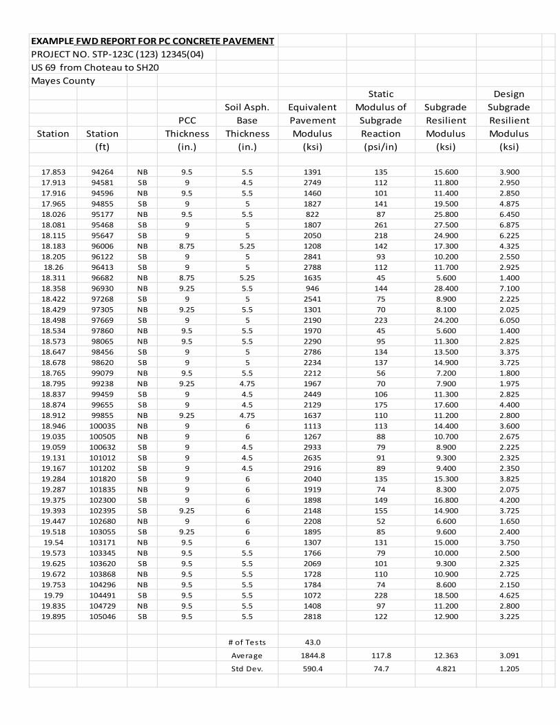
EXAMPLE FWD REPORT FOR PC CONCRETE PAVEMENT
PROJECT NO. STP‐123C (123) 12345(04)
US 69 from Choteau to SH20
Mayes County
Static Design
Soil Asph. Equivalent Modulus of Subgrade Subgrade
PCC Base Pavement Subgrade Resilient Resilient
Station Station Thickness Thickness Modulus Reaction Modulus Modulus
(ft) (in.) (in.) (ksi) (psi/in) (ksi) (ksi)
17.853 94264 NB 9.5 5.5 1391 135 15.600 3.900
17.913 94581 SB 9 4.5 2749 112 11.800 2.950
17.916 94596 NB 9.5 5.5 1460 101 11.400 2.850
17.965 94855 SB 9 5 1827 141 19.500 4.875
18.026 95177 NB 9.5 5.5 822 87 25.800 6.450
18.081 95468 SB 9 5 1807 261 27.500 6.875
18.115 95647 SB 9 5 2050 218 24.900 6.225
18.183 96006 NB 8.75 5.25 1208 142 17.300 4.325
18.205 96122 SB 9 5 2841 93 10.200 2.550
18.26 96413 SB 9 5 2788 112 11.700 2.925
18.311 96682 NB 8.75 5.25 1635 45 5.600 1.400
18.358 96930 NB 9.25 5.5 946 144 28.400 7.100
18.422 97268 SB 9 5 2541 75 8.900 2.225
18.429 97305 NB 9.25 5.5 1301 70 8.100 2.025
18.498 97669 SB 9 5 2190 223 24.200 6.050
18.534 97860 NB 9.5 5.5 1970 45 5.600 1.400
18.573 98065 NB 9.5 5.5 2290 95 11.300 2.825
18.647 98456 SB 9 5 2786 134 13.500 3.375
18.678 98620 SB 9 5 2234 137 14.900 3.725
18.765 99079 NB 9.5 5.5 2212 56 7.200 1.800
18.795 99238 NB 9.25 4.75 1967 70 7.900 1.975
18.837 99459 SB 9 4.5 2449 106 11.300 2.825
18.874 99655 SB 9 4.5 2129 175 17.600 4.400
18.912 99855 NB 9.25 4.75 1637 110 11.200 2.800
18.946 100035 NB 9 6 1113 113 14.400 3.600
19.035 100505 NB 9 6 1267 88 10.700 2.675
19.059 100632 SB 9 4.5 2933 79 8.900 2.225
19.131 101012 SB 9 4.5 2635 91 9.300 2.325
19.167 101202 SB 9 4.5 2916 89 9.400 2.350
19.284 101820 SB 9 6 2040 135 15.300 3.825
19.287 101835 NB 9 6 1919 74 8.300 2.075
19.375 102300 SB 9 6 1898 149 16.800 4.200
19.393 102395 SB 9.25 6 2148 155 14.900 3.725
19.447 102680 NB 9 6 2208 52 6.600 1.650
19.518 103055 SB 9.25 6 1895 85 9.600 2.400
19.54 103171 NB 9.5 6 1307 131 15.000 3.750
19.573 103345 NB 9.5 5.5 1766 79 10.000 2.500
19.625 103620 SB 9.5 5.5 2069 101 9.300 2.325
19.672 103868 NB 9.5 5.5 1728 110 10.900 2.725
19.753 104296 NB 9.5 5.5 1784 74 8.600 2.150
19.79 104491 SB 9.5 5.5 1072 228 18.500 4.625
19.835 104729 NB 9.5 5.5 1408 97 11.200 2.800
19.895 105046 SB 9.5 5.5 2818 122 12.900 3.225
# of Tests 43.0
Average 1844.8 117.8 12.363 3.091
Std Dev. 590.4 74.7 4.821 1.205