state graphs fsms - new mexico's flagship universityzbaker/ece238/slides/17.pdfstate graphs are...
TRANSCRIPT

18 STATEGRAPHS/FSMPage 1
ECE 238L © 2006
State GraphsFSMs

18 STATEGRAPHS/FSMPage 2
ECE 238L © 2006
Binary Counter State Graph
00
10
0111
Q1 Q0 N1 N0
0 0 0 10 1 1 01 0 1 11 1 0 0
State
Transition
State graphs are graphicalrepresentations of TT’s
They contain the same information:no more, no less

18 STATEGRAPHS/FSMPage 3
ECE 238L © 2006
Design Procedure Using State Graphs
1. Draw the state graph
2. Create an equivalent transition table
3. If transition table contains input don’t cares, - unfold it to a full transition table
4. Complete the design using KMaps, gates, FF’s

18 STATEGRAPHS/FSMPage 4
ECE 238L © 2006
State Graphs With Moore Outputs
00
10
0111
Z
Z
Q1 Q0 N1 N0 Z
0 0 0 1 10 1 1 0 01 0 1 1 01 1 0 0 1
Write the output next to the states it is asserted in…Underline it to make it more clear

18 STATEGRAPHS/FSMPage 5
ECE 238L © 2006
Another SG With A Moore Output
INC Q1 Q0 N1 N0 Z
0 0 0 0 0 10 0 1 0 1 00 1 0 1 0 00 1 1 1 1 11 0 0 0 1 11 0 1 1 0 01 1 0 1 1 01 1 1 0 0 1
00
10
0111
INC
INCINC
INC
INC’
INC’
INC’
INC’
Z
Z
Moore output shows up in multiple TT rows…

18 STATEGRAPHS/FSMPage 6
ECE 238L © 2006
State Graphs and Mealy Outputs
INC Q1 Q0 N1 N0 Y
0 0 0 0 0 00 0 1 0 1 00 1 0 1 0 00 1 1 1 1 01 0 0 0 1 01 0 1 1 0 01 1 0 1 1 01 1 1 0 0 1
00
10
0111
INC
INCINC
INC / Y
INC’
INC’
INC’
INC’
Mealy output is associated with an arc in SG

18 STATEGRAPHS/FSMPage 7
ECE 238L © 2006
Properly Formed State Graphs
• A properly formed state graph is both:
Complete
and
Conflict-free

18 STATEGRAPHS/FSMPage 8
ECE 238L © 2006
An Incomplete State Graph
• This SG is incomplete. Can you see why?
00
10
0111
INC
INCINC
INC
INC’INC’
INC’
What happens in state ’10’ when INC=0?

18 STATEGRAPHS/FSMPage 9
ECE 238L © 2006
An Incomplete State Graph
• This SG is incomplete. Can you see why?
00
10
0111
INC
INCINC
INC
INC’INC’
INC’
There is a missing row in the TT as well…
INC Q1 Q0 N1 N0
0 0 0 0 00 0 1 0 10 1 1 1 11 0 0 0 11 0 1 1 01 1 0 1 11 1 1 0 0

18 STATEGRAPHS/FSMPage 10
ECE 238L © 2006
Complete State Graphs
• For a SG to be complete:– Paths leaving each state must cover all cases
• To check:– OR together conditions on all arcs leaving a
given state– If result = ‘1’, state is complete– If result ≠ ‘1’, state is incomplete

18 STATEGRAPHS/FSMPage 11
ECE 238L © 2006
Checking for Completeness
00
10
0111
INC
INCINC
INC
INC’
INC’INC’
INC + INC’ = 1State 00 is OK
INC + INC’ = 1State 01 is OK
INC + INC’ = 1State 11 is OK
INC ≠ 1State 10 is not OK

18 STATEGRAPHS/FSMPage 12
ECE 238L © 2006
Alternate Check for Completeness
• Full transition table (no input don’t cares) should have 2n rows where:
n = (#inputs + #state variables)INC Q1 Q0 N1 N0
0 0 0 0 00 0 1 0 10 1 1 1 11 0 0 0 11 0 1 1 01 1 0 1 11 1 1 0 0
This only has 7 rows, something is missing…

18 STATEGRAPHS/FSMPage 13
ECE 238L © 2006
Additional Completeness Considerations
• If some input combination will never occur – Don’t need to enforce completeness
01INCCLR
What about the case of CLR•INC?
If INC=CLR=‘1’ will never occur,this incomplete state is OK
CLR’ • INC’

18 STATEGRAPHS/FSMPage 14
ECE 238L © 2006
Conflicts in State Graphs• This SG has a conflict, can you find it?
00
10
01
CLR’ • INC
CLR’ • INC’CLR
CLR
CLR
CLR’ • INCINC
CLR’ • INC
CLR’ • INC’
CLR’ • INC’
CLR’ • INC’CLR
11

18 STATEGRAPHS/FSMPage 15
ECE 238L © 2006
Conflicts in State Graphs• This SG has a conflict, can you find it?
00
10
01
CLR’ • INC
CLR’ • INC’CLR
CLR
CLR
CLR’ • INCINC
CLR’ • INC
CLR’ • INC’
CLR’ • INC’
CLR’ • INC’CLR
11
What happens in state ’10’ when CLR=INC=‘1’?

18 STATEGRAPHS/FSMPage 16
ECE 238L © 2006
Conflicts in State Graphs
One arc says to go to state 00,another says to go to state 11
This is a conflict…
00
10
01
CLR’ • INC
CLR’ • INC’CLR
CLR
CLR
CLR’ • INCINC
CLR’ • INC
CLR’ • INC’
CLR’ • INC’
CLR’ • INC’CLR
11
• This SG has a conflict, can you find it?

18 STATEGRAPHS/FSMPage 17
ECE 238L © 2006
Conflicts in State Graphs• The corresponding transition table has a
problem as well…
CLR INC Q1 Q0 N1 N0
0 0 0 0 0 00 0 0 1 0 10 0 1 0 1 00 0 1 1 1 10 1 0 0 0 10 1 0 1 1 01 - 1 0 0 0- 1 1 0 1 10 1 1 1 0 01 - - - 0 0
00
10
01
CLR’ • INC
CLR’ • INC’CLR
CLR
CLR
CLR’ • INCINC
CLR’ • INC
CLR’ • INC’
CLR’ • INC’CLR
CLR’ • INC’
11

18 STATEGRAPHS/FSMPage 18
ECE 238L © 2006
Conflicts in State Graphs
CLR INC Q1 Q0 N1 N0
0 0 0 0 0 00 0 0 1 0 10 0 1 0 1 00 0 1 1 1 10 1 0 0 0 10 1 0 1 1 01 - 1 0 0 0- 1 1 0 1 10 1 1 1 0 01 - - - 0 0
Do you want 2 TTrows active at the same time?
00
10
01
CLR’ • INC
CLR’ • INC’CLR
CLR
CLR
CLR’ • INCINC
CLR’ • INC
CLR’ • INC’
CLR’ • INC’CLR
CLR’ • INC’
11
• The corresponding transition table has a problem as well…

18 STATEGRAPHS/FSMPage 19
ECE 238L © 2006
Conflict-Free State Graphs
• For a State Graph to not have conflicts:– Paths leaving each state must not conflict with
one another• To check:
– For each pair of arcs leaving a given state, AND together their conditions
– If result = ‘0’, arcs have no conflict – If result ≠ ‘0’, arcs have a conflict

18 STATEGRAPHS/FSMPage 20
ECE 238L © 2006
Checking for Conflicts
00
10
01
CLR’ • INC
CLR’ • INC’CLR
CLR
CLR
CLR’ • INCINC
CLR’ • INC
CLR’ • INC’CLR
CLR’ • INC’
CLR’ • INC’ 11
CLR • (CLR’ • INC’) = 0These arcs OK
(CLR’ • INC’) • (CLR’ • INC) = 0These arcs OK
INC • CLR ≠ 0These arcs not OK Remember – you must do
all pairs of arcs leavingeach state…

18 STATEGRAPHS/FSMPage 21
ECE 238L © 2006
Alternate Check for Conflicts
• Full transition table (no input don’t cares) should have 2n rows where:
n = (#inputs + #state variables)
This has 18 rows, something is wrong…
CLR INC Q1 Q0 N1 N0
0 0 0 0 0 00 0 0 1 0 10 0 1 0 1 00 0 1 1 1 10 1 0 0 0 10 1 0 1 1 01 0 1 0 0 01 1 1 0 0 00 1 1 0 1 11 1 1 0 1 10 1 1 1 0 01 0 0 0 0 01 0 0 1 0 01 0 1 1 0 01 1 0 0 0 01 1 0 1 0 01 1 1 0 0 01 1 1 1 0 0

18 STATEGRAPHS/FSMPage 22
ECE 238L © 2006
Additional Conflict Considerations
• If some input combination will never occur – Don’t need to worry about conflicts
01INCCLR
If INC=CLR=‘1’ will never occur, the conflict shown here is OK.But, you will have to make a decision on how to write the TT
CLR’ • INC’

18 STATEGRAPHS/FSMPage 23
ECE 238L © 2006
Summary - Properly Formed State Graphs
• A properly formed state graph is both– Complete– Conflict-free
• Perform tests to ensure you have covered all the cases once and only once

18 STATEGRAPHS/FSMPage 24
ECE 238L © 2006
Summary – SG’s vs. TT’s
• A state graph is simply a graphical way of writing a Transition Table– No additional information
• You should be adept at converting between them
• Design is always done from TT to KMaps to gates/FF’s
00
10
0111INC
INCINC
INC
INC’
INC’
INC’
INC’
INC Q1 Q0 N1 N0
0 0 0 0 00 0 1 0 10 1 0 1 00 1 1 1 11 0 0 0 11 0 1 1 01 1 0 1 11 1 1 0 0

18 STATEGRAPHS/FSMPage 25
ECE 238L © 2006
Finite State Machines

18 STATEGRAPHS/FSMPage 26
ECE 238L © 2006
State Machine Concepts
• State, current state, next state, state registers
• IFL, OFL, Moore outputs, Mealy outputs• Transition tables
– With output don’t cares (X’s)– With input don’t cares (-’s)
• State graphs– And their correspondence to TT’s

18 STATEGRAPHS/FSMPage 27
ECE 238L © 2006
Counters as State Machines
• A counter is a state machine– Where the state encodings are significant
Q0
Q2Q3
Q1
00000001
0010
0011
01000101
0110
0111
1000
1001
7 SegmentDecoder

18 STATEGRAPHS/FSMPage 28
ECE 238L © 2006
State Machines
• A state machine is a sequential circuit which progresses through a series of states in reponse to inputs– The output values are usually significant– The state encodings are usually not significant
• Unlike with counters

18 STATEGRAPHS/FSMPage 29
ECE 238L © 2006
State Encodings
• In this machine, the state encodings don’t matter
• The output values do…
…Event 1Event 2Event 1
Event 2 Event 3
Output1Output2 Output3

18 STATEGRAPHS/FSMPage 30
ECE 238L © 2006
A State Machine Controller for a Photocopier
FiniteState
Machine
Lamps
Motors
Display
Buttons
Timers
Switches
Inputs Outputs
1) FSM receives inputs from copier2) FSM generates control outputs in response3) States help it remember where it is in the copy process…

18 STATEGRAPHS/FSMPage 31
ECE 238L © 2006
A Sequence Detector FSM
S2
S1S3
Xin’
XinXin
Xin’
Xin’
Xin
Z
S0Because the encodings don’t matter, we will use symbolic state names
What does this machine do?

18 STATEGRAPHS/FSMPage 32
ECE 238L © 2006
A Sequence Detector FSM
S2
S1S3
Xin’
XinXin
Xin’
Xin’
Xin
Z
S0
It is a sequence detector.
It has 1 input: ‘Xin’ and one output: ‘Z’
It detects the sequence 0..1..1 on the input. When detected, output ‘Z’ is asserted.

18 STATEGRAPHS/FSMPage 33
ECE 238L © 2006
A Sequence Detector FSM
S2
S1S3
Xin’
XinXin
Xin’
Xin’
Xin
Z
S0
As long as Xin=1, we stay in state S0
1..1..1..1..1..

18 STATEGRAPHS/FSMPage 34
ECE 238L © 2006
A Sequence Detector FSM
S2
S1S3
Xin’
XinXin
Xin’
Xin’
Xin
Z
S0
When Xin=0, we go to state S1
1..1..1..1..1..0..

18 STATEGRAPHS/FSMPage 35
ECE 238L © 2006
A Sequence Detector FSM
S2
S1S3
Xin’
XinXin
Xin’
Xin’
Xin
Z
S0
As long as Xin=0, we stay in state S1
1..1..1..1..1..0..0..0..0..

18 STATEGRAPHS/FSMPage 36
ECE 238L © 2006
A Sequence Detector FSM
S2
S1S3
Xin’
XinXin
Xin’
Xin’
Xin
Z
S0
When Xin=1, we go to state S2
1..1..1..1..1..0..0..0..0..1..

18 STATEGRAPHS/FSMPage 37
ECE 238L © 2006
A Sequence Detector FSM
S2
S1S3
Xin’
XinXin
Xin’
Xin’
Xin
Z
S0
If Xin=1 again, we go to state S3
1..1..1..1..1..0..0..0..0..1..1
SUCCESS! Raise the Z output

18 STATEGRAPHS/FSMPage 38
ECE 238L © 2006
A Sequence Detector FSM
S2
S1S3
Xin’
XinXin
Xin’
Xin’
Xin
Z
S0
Once we enter state S3, we never leave…

18 STATEGRAPHS/FSMPage 39
ECE 238L © 2006
A Sequence Detector FSM
S2
S1S3
Xin’
XinXin
Xin’
Xin’
Xin
Z
S0
What if we don’t see the second Xin=1?
1..1..1..1..1..0..0..0..0..1..0..

18 STATEGRAPHS/FSMPage 40
ECE 238L © 2006
Implementing the Sequence Detector FSM
1. Create symbolic Transition Table2. Assign state encoding3. Create conventional Transition Table4. Do standard implementation steps
Xin CS NS Z
0 S0 S1 01 S0 S0 00 S1 S1 01 S1 S2 00 S2 S1 01 S2 S3 0- S3 S3 1
Xin Q1 Q0 N1 N0 Z
0 0 0 0 1 01 0 0 0 0 00 0 1 0 1 01 0 1 1 0 00 1 0 0 1 01 1 0 1 1 0- 1 1 1 1 1
Symbolic TT Conventional TTState Assignment
S0 = 00S1 = 01S2 = 10S3 = 11

18 STATEGRAPHS/FSMPage 41
ECE 238L © 2006
Sequence Detector Implementation
Q1
CLK
Q0
CLK
Q1
D Q
D Q
Q0N1
N0
Q1XinXinQ0
Xin’Q1
Z
N1 = Q1•Q0 + Xin•Q1 + Xin•Q0N0 = Xin’ + Q1Z = Q1•Q0

18 STATEGRAPHS/FSMPage 42
ECE 238L © 2006
A Problem With the Sequence Detector
• This FSM only detects first occurrence of 011 on input…
• Here is a timing diagram– actual screenshot from a simulation
1 1 1 1 1 10 0 0

18 STATEGRAPHS/FSMPage 43
ECE 238L © 2006
Improved Sequence Detector
• This starts over each time 011 is detected…
S2
S1Xin’
Xin
Xin
Xin’
Xin’
Xin
Z
S0
S3
Xin’
Xin

18 STATEGRAPHS/FSMPage 44
ECE 238L © 2006
Improved Detector Timing Diagram
0 0 0 1 1 1 0 1 1 0 001
Z=1 any time state is S3
Looking at Xin, does it look like Z is a cycle late?
18 STATEGRAPHS/FSMPage 45
ECE 238L © 2006
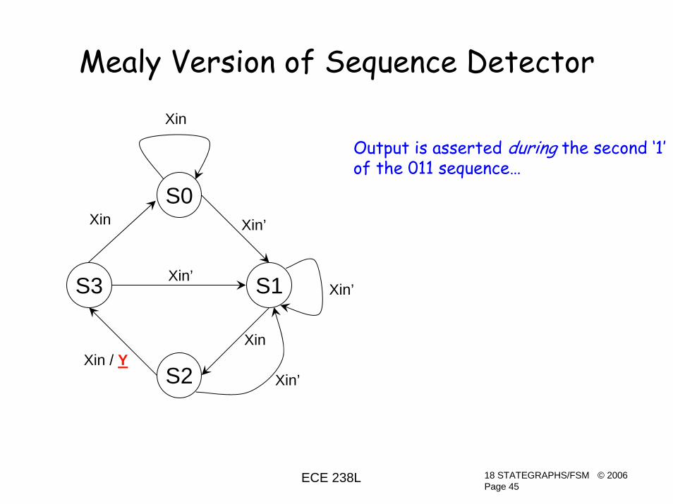
Mealy Version of Sequence Detector
S2
S1Xin’
XinXin / Y
Xin
Xin’
Xin’
S0
S3
Xin’Xin
Output is asserted during the second ‘1’of the 011 sequence…

18 STATEGRAPHS/FSMPage 46
ECE 238L © 2006
Mealy Version Timing Diagram
0 1 1 1 0 1 1 1
Y
Note how Mealy output follows input during state S2
Output is a cycle earlier than in Moore machine –it appears in S2 rather than in S3

18 STATEGRAPHS/FSMPage 47
ECE 238L © 2006
Simplified Mealy Sequence Detector
• A characteristic ofMealymachines is they often require fewer states than Moore machines
• Here is simplified but equivalent FSM
S2
S1
Xin
Xin / Y
Xin
Xin’
Xin’
S0Xin’

18 STATEGRAPHS/FSMPage 48
ECE 238L © 2006
Example FSM’s
Two Car Wash Controllers

18 STATEGRAPHS/FSMPage 49
ECE 238L © 2006
Basic Car Wash FSM Operation
1. Wait for a token to be inserted2. Reset timer3. Turn on water pump until timer expires4. Start over
• This assumes existence of:– Token acceptance mechanism– Timer– Digitally-controlled water pump

18 STATEGRAPHS/FSMPage 50
ECE 238L © 2006
Basic Car Wash FSM SG
S_SPRAY
S_TOKEN
TOKEN
TOKEN’
CLRT
S_IDLE
TDONE’
TDONE
Wait for token…
Clear timer…
Spray car whilewaiting for timerto expire…
SPRAY

18 STATEGRAPHS/FSMPage 51
ECE 238L © 2006
TOKEN TDONE CS NS CLRT SPRAY
0 - S_IDLE S_IDLE 0 01 - S_IDLE S_TOKEN 0 0- - S_TOKEN S_SPRAY 1 0- 0 S_SPRAY S_SPRAY 0 1- 1 S_SPRAY S_IDLE 0 1
TOKEN TDONE Q1 Q0 N1 N0 CLRT SPRAY
0 - 0 0 0 0 0 01 - 0 0 0 1 0 0- - 0 1 1 0 1 0- 0 1 0 1 0 0 1- 1 1 0 0 0 0 1
TOKEN TDONE Q1 Q0 N1 N0 CLRT SPRAY
0 0 0 0 0 0 0 00 0 0 1 1 0 1 00 0 1 0 1 0 0 10 0 1 1 X X X X0 1 0 0 0 0 0 00 1 0 1 1 0 1 00 1 1 0 0 0 0 10 1 1 1 X X X X1 0 0 0 0 1 0 01 0 0 1 1 0 1 01 0 1 0 1 0 0 11 0 1 1 X X X X1 1 0 0 0 1 0 01 1 0 1 1 0 1 01 1 1 0 0 0 0 11 1 1 1 X X X X

18 STATEGRAPHS/FSMPage 52
ECE 238L © 2006
Basic Car Wash Implementation
D Q
D Q
Q1N1
CLK
Q0N0
CLK
Q0
Q1TDONE’
TOKENQ1’Q0’
SPRAY
CLRT
This is what you get from a KMap solution

18 STATEGRAPHS/FSMPage 53
ECE 238L © 2006
Simplified State Graph
S_SPRAY
TOKEN
CLRT
TOKEN’
S_IDLE
TDONE’
TDONE
SPRAY
Clear timer while waiting for a token and eliminate a state
TOKEN TDONE CS NS CLRT SPRAY
0 - S_IDLE S_IDLE 1 01 - S_IDLE S_SPRAY 1 0- 0 S_SPRAY S_SPRAY 0 1- 1 S_SPRAY S_IDLE 0 1

18 STATEGRAPHS/FSMPage 54
ECE 238L © 2006
Simplified Car Wash Implementation
State Encoding: S_IDLE = 0, S_SPRAY = 1
NS = CS’•TOKEN + CS•TDONE’CLRT = CS’SPRAY = CS
CS
NS
TDONE’
SPRAYD QCS
CS’TOKEN
CLRTCLK

18 STATEGRAPHS/FSMPage 55
ECE 238L © 2006
A Fancy Car Wash Controller
• Two types of washes:– Regular wash (spray only) = 1 token– Deluxe wash (spray, soap, spray) = 2 tokens
• Customer:– Inserts 1 token and pushes START for Regular– Inserts 2 tokens for Deluxe

18 STATEGRAPHS/FSMPage 56
ECE 238L © 2006
S3
TOKEN’
CLRT1
S0
S1
TOKEN
TOKEN’ • START’
TOKEN • START’
S2 T1DONE’SPRAY, CLRT2
T1DONE
T2DONE’
S4
T2DONE
SOAP, CLRT1
SPRAYT1DONE’
T1DONE
START
Straightforward process to write transition table and reduce to gates
Creativity in FSM designis designing the initialstate graph…

18 STATEGRAPHS/FSMPage 57
ECE 238L © 2006
Enhancements to Fancy Controller

18 STATEGRAPHS/FSMPage 58
ECE 238L © 2006
S3
TOKEN’
CLRT1,ACCEPTCOIN
S0
S1
TOKEN
TOKEN’ • START’
TOKEN • START’
S2 T1DONE’SPRAY, CLRT2
T1DONE
T2DONE’
S4
T2DONE
SOAP, CLRT1
SPRAYT1DONE’
T1DONE
START
There is no way to cause coinboxto refuse tokens. Coins insertedafter wash commences are presumably kept by the machine.
Let’s add an ACCEPTCOIN outputto control when coinbox willaccept tokens…
ACCEPTCOIN

18 STATEGRAPHS/FSMPage 59
ECE 238L © 2006
S3
TOKEN’
CLRT1
S0
S1
TOKEN
TOKEN’ • START’
TOKEN • START’
S2 T1DONE’SPRAY, CLRT2
T1DONE
T2DONE’
S4
T2DONE
SOAP, CLRT1
SPRAYT1DONE’
T1DONE
START
ACCEPTCOIN
If customer pushes START atprecisely the same time as heinserts another TOKEN, theFSM will take the token, butdeliver a Regular Wash.
That is, START hasprecedence over TOKEN
ACCEPTCOIN

18 STATEGRAPHS/FSMPage 60
ECE 238L © 2006
S3
TOKEN’
CLRT1
S0
S1
TOKEN
TOKEN’ • START’
TOKEN
S2 T1DONE’SPRAY, CLRT2
T1DONE
T2DONE’
S4
T2DONE
SOAP, CLRT1
SPRAYT1DONE’
T1DONE
START•TOKEN’
ACCEPTCOIN
This changes the precedence sothe machine won’t steal the second token, but will give a deluxe wash in this case.
ACCEPTCOIN
18 STATEGRAPHS/FSMPage 61
ECE 238L © 2006
Completeness and Conflict Revisited
• State S1 is a typical problem spot
• Carefully analyze the state graph to ensure no conflicts exist and that all cases covered.

18 STATEGRAPHS/FSMPage 62
ECE 238L © 2006
Resetting State Machines
• Ability to reset the FSM is essential for testing most systems
• Always include a reset capability– Add CLR signal to state graph– Use flip flops with clear inputs
– Either method will work

18 STATEGRAPHS/FSMPage 63
ECE 238L © 2006
Another Example
An Electronic Key Lock

18 STATEGRAPHS/FSMPage 64
ECE 238L © 2006
1) There are 10 keypads 0-92) The unlock sequence is 7..8..93) When a pad is pushed the signal for that number is asserted4) When any of the keypads are pushed a PUSHED signal is asserted5) If you push a number out of sequence, you get an error indicator
and you get to start over6) After three wrong tries, you must wait ½ hr. before trying again7) If you entered the correct sequence, the lock unlocks.8) Once the lock has opened, nothing happens until it is manually
locked again.
Inputs: Keypads signals 0-9 Outputs: INCPUSHED signal CLRTIMERECNT3 (error count = 3) CLRCNTRWAITDONE ERRORLOCKED UNLOCK
Example: Electronic Key Lock

18 STATEGRAPHS/FSMPage 65
ECE 238L © 2006
ECNT3’
A
F E
CB
D
Start
PUSHED•7
PUSHED•7’/INC
PUSHED•9/ UNLOCK
ERRORECNT3/ CLRTIMER
WAITDONE’
WAITDONE/CLRCNTR
PUSHED’
PUSHED’
PUSHED’
LOCKED’
LOCKED/ CLRCNTR
PUSHED•8
PUSHED•8’/INC
PUSHED•9’/INC

18 STATEGRAPHS/FSMPage 66
ECE 238L © 2006
Let’s create the transition table…
ECNT3’
A
F E
CB
D
StartPUSHED•7
PUSHED•7’/INC
PUSHED•9/ UNLOCK
ERRORECNT3/ CLRTIMERWAITDONE’
WAITDONE/CLRCNTR
PUSHED’
PUSHED’PUSHED’
LOCKED’
LOCKED/ CLRCNTR
PUSHED•8
PUSHED•8’/INC PUSHED•9’/
INC
PUSHED 7 8 9 ECNT3 WAITDONE LOCKED STATE NEXTSTATE INC ERROR CLRCNTR CLRTIMER UNLOCK
0 - - - - - - A A 0 0 0 - 01 0 - - - - - A E 1 0 0 - 01 1 - - - - - A B 0 0 0 - 00 - - - - - - B B 0 0 0 - 01 - 0 - - - - B E 1 0 0 - 01 - 1 - - - - B C 0 0 0 - 00 - - - - - - C C 0 0 0 - 01 - - 0 - - - C E 1 0 0 - 01 - - 1 - - - C D 0 0 - - 1- - - - - - 0 D D - 0 - - 0- - - - - - 1 D A 0 0 1 - 0- - - - 0 - - E A 0 1 0 - 0- - - - 1 - - E F - 1 0 1 0- - - - - 0 - F F - 0 0 0 0- - - - - 1 - F A 0 0 1 0 0

18 STATEGRAPHS/FSMPage 67
ECE 238L © 2006
PUSHED 7 8 9 ECNT3 WAITDONE LOCKED STATE NEXTSTATE INC ERROR CLRCNTR CLRTIMER UNLOCK
0 0 0 0 0 0 0 A A 0 0 0 - 00 0 0 0 0 0 1 A A 0 0 0 - 00 0 0 0 0 1 0 A A 0 0 0 - 00 0 0 0 0 1 1 A A 0 0 0 - 00 0 0 0 1 0 0 A A 0 0 0 - 00 0 0 0 1 0 1 A A 0 0 0 - 00 0 0 0 1 1 0 A A 0 0 0 - 00 0 0 0 1 1 1 A A 0 0 0 - 00 0 0 1 0 0 0 A A 0 0 0 - 00 0 0 1 0 0 1 A A 0 0 0 - 00 0 0 1 0 1 0 A A 0 0 0 - 00 0 0 1 0 1 1 A A 0 0 0 - 00 0 0 1 1 0 0 A A 0 0 0 - 00 0 0 1 1 0 1 A A 0 0 0 - 00 0 0 1 1 1 0 A A 0 0 0 - 0
Now let’s expand State A
…

18 STATEGRAPHS/FSMPage 68
ECE 238L © 2006
This is going to get ugly fast…
• 7 inputs + 3 state bits = 1024 rows in TT
• Can you do a 10-variable KMap?
• There is a technique called One-Hot state machines we can use instead…