state as a service - diva portal
TRANSCRIPT

Master of Science ThesisStockholm, Sweden 2012
TRITA-ICT-EX-2012:31
A H M A D U L L A H A L N O O R
Towards Stateful Cloud Services
State as a Service
K T H I n f o r m a t i o n a n d
C o m m u n i c a t i o n T e c h n o l o g y


State as a Service
Towards Stateful Cloud Services
AHMADULLAH ALNOOR
Master of Science ThesisSupervisor : Lars Hammer, Principal Software Architect, MDCC/Microsoft
Examiner : Vladimir Vlassov, Associate Professor, KTH
Royal Institute of Technology (KTH), Stockholm, Sweden, 2012


Abstract
Cloud ERP or Enterprise Resource Planning (ERP) as a Cloud Service deliversvalue by reducing initial and long term operating costs since infrastructure, platformand (certain) application management tasks are delegated to a specialist provider.Questions present at intersection of the ERP challenge landscape and the CloudComputing opportunity horizon include characterization of Cloud friendly ERPmodules and adaptation of stateful (on-premises ERP) components to a statelessplatform.
Contributions of this thesis work include the R.A.I.N. Cloud fitness criteriathat encompasses Responsiveness, Availability, I/O and Native support aspects ofCloud Services. More importantly, the State abstraction, a reliable and elastic statemanagement framework employing Autonomic Computing and Redo Recovery con-structs is introduced. Construction of abstraction properties, namely, affinity awarestate preservation and recovery consider Cloud strengths of scaling out and reliabil-ity as well as peculiarities of Cloud billing model. Proof-of-concept implementationof State as a Service has been comprehensively detailed and evaluated advocatinginfrastructure layer support of the kind and associated tooling.
iii


Dedication
To teachers.
v


Acknowledgment
nani gigantum humeris insidentes
- Bernard de Chartres
This independent work carries enabling contributions from individuals and or-ganizations alike, to whom appreciation is extended.
Gratitude is duly expressed towards Mr. Lars Hammer and Prof. VladimirVlassov for their guidance, patience and confidence. Assistance from K.T.H. andI.A.E.S.T.E. with logistics of performing this degree project is also highly valued.Many thanks are in order to Mr. David Worthington, my manager, and the largergroup at MDCC (Microsoft Development Center Copenhagen) for the time and re-sources we shared.
Further debit has been incurred and credit thus offered to my parents and sib-lings for sharing my dreams and bearing my absence.
Ahmadullah Alnoor
12. February 2012Virum, Denmark
vii

Contents
Abstract iii
Acknowledgment vii
Contents viii
List of Acronyms xi
List of Figures xii
List of Algorithms xiii
List of Tables xiv
1 Vision 11.1 The ERP Problem . . . . . . . . . . . . . . . . . . . . . . . . . . . . 11.2 The Cloud Incentive . . . . . . . . . . . . . . . . . . . . . . . . . . . 21.3 Scenarios . . . . . . . . . . . . . . . . . . . . . . . . . . . . . . . . . 3
2 Background 72.1 Cloud Computing . . . . . . . . . . . . . . . . . . . . . . . . . . . . . 7
2.1.1 Rationale . . . . . . . . . . . . . . . . . . . . . . . . . . . . . 72.1.2 Flavors & Features . . . . . . . . . . . . . . . . . . . . . . . . 72.1.3 Adoption . . . . . . . . . . . . . . . . . . . . . . . . . . . . . 9
2.2 Enterprise Resource Planning . . . . . . . . . . . . . . . . . . . . . . 92.2.1 Early Days . . . . . . . . . . . . . . . . . . . . . . . . . . . . 92.2.2 Contemporary Solutions . . . . . . . . . . . . . . . . . . . . . 102.2.3 Research Challenges . . . . . . . . . . . . . . . . . . . . . . . 102.2.4 Industry Offerings . . . . . . . . . . . . . . . . . . . . . . . . 11
3 Analysis 133.1 Cloud Service Characteristics . . . . . . . . . . . . . . . . . . . . . . 13
3.1.1 Responsive . . . . . . . . . . . . . . . . . . . . . . . . . . . . 133.1.2 Available . . . . . . . . . . . . . . . . . . . . . . . . . . . . . 143.1.3 I/O . . . . . . . . . . . . . . . . . . . . . . . . . . . . . . . . 14
viii

CONTENTS ix
3.1.4 Native . . . . . . . . . . . . . . . . . . . . . . . . . . . . . . . 14
3.2 The Nature of State . . . . . . . . . . . . . . . . . . . . . . . . . . . 14
3.2.1 Application State . . . . . . . . . . . . . . . . . . . . . . . . . 15
3.2.2 Session State . . . . . . . . . . . . . . . . . . . . . . . . . . . 15
3.3 Stateless Cloud - Stateful Service . . . . . . . . . . . . . . . . . . . . 15
3.3.1 Server Side State . . . . . . . . . . . . . . . . . . . . . . . . . 16
3.3.2 Client Side State . . . . . . . . . . . . . . . . . . . . . . . . . 17
3.3.3 Virtual Machine Cloning . . . . . . . . . . . . . . . . . . . . . 17
3.3.4 Redo Recovery . . . . . . . . . . . . . . . . . . . . . . . . . . 18
3.4 State Abstraction - State as a Service . . . . . . . . . . . . . . . . . 18
3.5 Autonomicity . . . . . . . . . . . . . . . . . . . . . . . . . . . . . . . 18
3.5.1 Goals & Means . . . . . . . . . . . . . . . . . . . . . . . . . . 19
3.5.2 Healing & Optimization . . . . . . . . . . . . . . . . . . . . . 19
3.6 Summary . . . . . . . . . . . . . . . . . . . . . . . . . . . . . . . . . 20
4 Solution 21
4.1 Properties . . . . . . . . . . . . . . . . . . . . . . . . . . . . . . . . . 21
4.2 Architecture . . . . . . . . . . . . . . . . . . . . . . . . . . . . . . . . 22
4.2.1 Components . . . . . . . . . . . . . . . . . . . . . . . . . . . 22
4.2.2 Completeness . . . . . . . . . . . . . . . . . . . . . . . . . . . 23
4.3 Use Cases . . . . . . . . . . . . . . . . . . . . . . . . . . . . . . . . . 25
4.3.1 The State Service for Stateful Services . . . . . . . . . . . . . 25
4.3.2 Elasticity . . . . . . . . . . . . . . . . . . . . . . . . . . . . . 25
4.3.3 Fault Tolerance . . . . . . . . . . . . . . . . . . . . . . . . . . 25
4.4 Algorithms . . . . . . . . . . . . . . . . . . . . . . . . . . . . . . . . 27
4.4.1 State Preservation . . . . . . . . . . . . . . . . . . . . . . . . 27
4.4.2 Load Measurement . . . . . . . . . . . . . . . . . . . . . . . . 28
4.4.3 Load Balancing . . . . . . . . . . . . . . . . . . . . . . . . . . 28
4.4.4 Elasticity . . . . . . . . . . . . . . . . . . . . . . . . . . . . . 29
4.4.5 Actuator . . . . . . . . . . . . . . . . . . . . . . . . . . . . . 30
4.4.6 Session Recovery . . . . . . . . . . . . . . . . . . . . . . . . . 32
5 Implementation 33
5.1 Design . . . . . . . . . . . . . . . . . . . . . . . . . . . . . . . . . . . 33
5.1.1 Cloud Infrastructure . . . . . . . . . . . . . . . . . . . . . . . 33
5.1.2 Computation . . . . . . . . . . . . . . . . . . . . . . . . . . . 33
5.1.3 Persistence . . . . . . . . . . . . . . . . . . . . . . . . . . . . 34
5.1.4 Elasticity . . . . . . . . . . . . . . . . . . . . . . . . . . . . . 35
5.1.5 Recovery . . . . . . . . . . . . . . . . . . . . . . . . . . . . . 36
5.1.6 Fault Tolerance . . . . . . . . . . . . . . . . . . . . . . . . . . 36
5.2 Construction . . . . . . . . . . . . . . . . . . . . . . . . . . . . . . . 36
5.2.1 OrderService . . . . . . . . . . . . . . . . . . . . . . . . . . . 36
5.2.2 ServiceWrapper . . . . . . . . . . . . . . . . . . . . . . . . . . 37
5.2.3 Store . . . . . . . . . . . . . . . . . . . . . . . . . . . . . . . . 38

x CONTENTS
5.2.4 Client Interface (Proxy) . . . . . . . . . . . . . . . . . . . . . 385.2.5 Storage Interface (Proxy) . . . . . . . . . . . . . . . . . . . . 395.2.6 Actuator . . . . . . . . . . . . . . . . . . . . . . . . . . . . . 415.2.7 Monitor . . . . . . . . . . . . . . . . . . . . . . . . . . . . . . 41
5.3 Additions & Refactoring . . . . . . . . . . . . . . . . . . . . . . . . . 435.4 Tools & Technologies . . . . . . . . . . . . . . . . . . . . . . . . . . 45
5.4.1 Windows Azure . . . . . . . . . . . . . . . . . . . . . . . . . . 455.4.2 Azure SDK . . . . . . . . . . . . . . . . . . . . . . . . . . . . 455.4.3 Microsoft .NET Framework 4.0 . . . . . . . . . . . . . . . . . 455.4.4 Windows Azure Tools for Microsoft Visual Studio . . . . . . 465.4.5 Windows Azure Platform Management Portal . . . . . . . . . 46
5.5 Code Metrics Analysis . . . . . . . . . . . . . . . . . . . . . . . . . . 46
6 Evaluation 496.1 Cost . . . . . . . . . . . . . . . . . . . . . . . . . . . . . . . . . . . . 496.2 Performance . . . . . . . . . . . . . . . . . . . . . . . . . . . . . . . . 506.3 Reliability . . . . . . . . . . . . . . . . . . . . . . . . . . . . . . . . . 51
6.3.1 Tenant Service Fails . . . . . . . . . . . . . . . . . . . . . . . 536.3.2 Monitor Fails . . . . . . . . . . . . . . . . . . . . . . . . . . . 536.3.3 Actuator Fails . . . . . . . . . . . . . . . . . . . . . . . . . . 546.3.4 Client Interface Fails . . . . . . . . . . . . . . . . . . . . . . . 556.3.5 Service Recovery . . . . . . . . . . . . . . . . . . . . . . . . . 55
6.4 Scalability . . . . . . . . . . . . . . . . . . . . . . . . . . . . . . . . . 576.4.1 Elasticity . . . . . . . . . . . . . . . . . . . . . . . . . . . . . 58
7 Directions\Future & Related Work 637.1 Cloud Integration . . . . . . . . . . . . . . . . . . . . . . . . . . . . . 637.2 Tooling . . . . . . . . . . . . . . . . . . . . . . . . . . . . . . . . . . 637.3 Log Management . . . . . . . . . . . . . . . . . . . . . . . . . . . . . 647.4 Idempotence . . . . . . . . . . . . . . . . . . . . . . . . . . . . . . . 647.5 Further Tests . . . . . . . . . . . . . . . . . . . . . . . . . . . . . . . 647.6 R.A.I.N-fall . . . . . . . . . . . . . . . . . . . . . . . . . . . . . . . . 657.7 Related Work . . . . . . . . . . . . . . . . . . . . . . . . . . . . . . . 65
8 Revision 678.1 Requirements Revisited . . . . . . . . . . . . . . . . . . . . . . . . . 678.2 Solution Brief . . . . . . . . . . . . . . . . . . . . . . . . . . . . . . . 678.3 Measurement Observations . . . . . . . . . . . . . . . . . . . . . . . 688.4 Conclusion . . . . . . . . . . . . . . . . . . . . . . . . . . . . . . . . 68
A Windows Azure Billing Model 69
Bibliography 71

List of Acronyms
B2B Business to Business
B2C Business to Consumer
CO Control Objective
ERP Enterprise Resource Planning
IaaS Infrastructure as a Service
OGSI Open Grid Services Infrastructure
PaaS Platform as a Service
ROI Return On Investment
SaaS Software as a Service
SLA Service Level Agreement
SLO Service Level Objective
SOA Service Oriented Architecture
VM Virtual Machine
WSRF Web Services Resource Framework
xi

List of Figures
1.1 Cloud ERP Offering . . . . . . . . . . . . . . . . . . . . . . . . . . . . . 21.2 Cloud ERP Adoption Scenarios . . . . . . . . . . . . . . . . . . . . . . . 5
4.1 State as a ServiceFault Tolerant Architecture for Elastic Stateful Services . . . . . . . . . 24
4.2 The State Service for Stateful Services . . . . . . . . . . . . . . . . . . . 264.3 Resource Elasticity . . . . . . . . . . . . . . . . . . . . . . . . . . . . . . 264.4 Fault Tolerance . . . . . . . . . . . . . . . . . . . . . . . . . . . . . . . . 274.5 Sample execution of Algorithm 4 . . . . . . . . . . . . . . . . . . . . . . 30
5.1 Order Service . . . . . . . . . . . . . . . . . . . . . . . . . . . . . . . . . 375.2 Service Wrapper - Structure . . . . . . . . . . . . . . . . . . . . . . . . . 375.3 Service Wrapper - Flow . . . . . . . . . . . . . . . . . . . . . . . . . . . 385.4 State Store . . . . . . . . . . . . . . . . . . . . . . . . . . . . . . . . . . 395.5 Client Interface - Structure . . . . . . . . . . . . . . . . . . . . . . . . . 405.6 Client Interface - Method Flow . . . . . . . . . . . . . . . . . . . . . . . 415.7 Storage Proxy . . . . . . . . . . . . . . . . . . . . . . . . . . . . . . . . . 425.8 Actuator - Structure . . . . . . . . . . . . . . . . . . . . . . . . . . . . . 425.9 Monitor - Structure . . . . . . . . . . . . . . . . . . . . . . . . . . . . . 435.10 Monitor - Flow . . . . . . . . . . . . . . . . . . . . . . . . . . . . . . . . 44
6.1 Average Response times for population sizes . . . . . . . . . . . . . . . . 526.2 Connections refused for population sizes . . . . . . . . . . . . . . . . . . 526.3 Response time variation . . . . . . . . . . . . . . . . . . . . . . . . . . . 556.4 Recovery cost distribution . . . . . . . . . . . . . . . . . . . . . . . . . . 576.5 Requests / second . . . . . . . . . . . . . . . . . . . . . . . . . . . . . . 586.6 % of Processor Time Alloted . . . . . . . . . . . . . . . . . . . . . . . . 596.7 Arc Elasticity . . . . . . . . . . . . . . . . . . . . . . . . . . . . . . . . . 606.8 Elastic Execution . . . . . . . . . . . . . . . . . . . . . . . . . . . . . . . 61
xii

List of Algorithms
1 Log Session Interactions . . . . . . . . . . . . . . . . . . . . . . . . . 282 Calculate Performance Counters . . . . . . . . . . . . . . . . . . . . 293 Rank Service Instances . . . . . . . . . . . . . . . . . . . . . . . . . . 294 Provision Resources . . . . . . . . . . . . . . . . . . . . . . . . . . . 315 Actuate Elasticity . . . . . . . . . . . . . . . . . . . . . . . . . . . . 326 Recover Client Session . . . . . . . . . . . . . . . . . . . . . . . . . . 32
xiii

List of Tables
5.1 Implementation Code Metrics Analysis . . . . . . . . . . . . . . . . . . . 475.2 Test Code Metrics Analysis . . . . . . . . . . . . . . . . . . . . . . . . . 47
6.1 Service Response Time . . . . . . . . . . . . . . . . . . . . . . . . . . . . 506.2 Service Response Time Breakdown . . . . . . . . . . . . . . . . . . . . . 506.3 Recovery Cost Distribution . . . . . . . . . . . . . . . . . . . . . . . . . 56
xiv

Chapter 1
Vision
Cloud Computing has come of age and has attracted wide spread though cau-tious interest. The Enterprise Resource Planning (ERP) industry relies upon stablecontemporary architectures and technologies to offer value to its customers. Thischapter explores the intersection of ERP challenges and Cloud opportunities.
1.1 The ERP Problem
Enterprises are typically structured into operational entities woven together by workflow processes. The structure and processes are, to varying degree, hidden from theclients and partners of the enterprise. Business to Consumer (B2C) and Business toBusiness (B2B) interactions occur through known and well defined service points.Organizations strive to avoid propagation of internal and external changes. Coop-eration and value addition demands organizing enterprises, often hierarchically, ofvarious sizes and market sectors.
Computerization of enterprises and business has traditionally remained alignedto problem domain structure and dynamics. Contemporary software packages offervarious sets of add-on features that build upon common denominator capabilities.Enterprise information and processes are managed internally and selectively ex-posed via different interfaces. Effort is made to isolate and localize modificationsto internal processes and external contracts.
Modeling the enterprise by ERP products confronts them with significant chal-lenges. Deployment and upgrade expense has only increased, even minor patchescome no cheaper. Enterprises continuously spend to provide for and maintain suf-ficient infrastructure. Further tax is introduced when ensuring reliability and re-covery. More interestingly, the on premises installation model hampers on demandscaling of the service delivered by the ERP product.
1

2 CHAPTER 1. VISION
Figure 1.1: Cloud ERP Offering
1.2 The Cloud Incentive
The forecast is overcast. The mist of Cloud Computing carries within the conceptsof Infrastructure as a Service (IaaS), Platform as a Service (PaaS) and Softwareas a Service (SaaS). Here, Infrastructure refers to computing, communication andstorage resources whereas Platform encapsulates enabling resources including oper-ating systems and application development as well as deployment services. Finally,SaaS extends Service Oriented Architecture (SOA) from fine grained operations toricher applications. The common trait among these Cloud layers is that of utilitycomputing whereby resources are made available and scaled on demand allowingfor a pay per use billing model. Utilities at each Cloud crust are provisioned andreclaimed in an elastic fashion with swift sensitivity to demand[27].
Cloud ERP - the notion of ERP as a Cloud Service carries exciting opportunitiesand tough challenges. As a service offering, Cloud ERP delivers value by reducinginitial and long term operating costs by delegating infrastructure, platform andapplication management to a specialist organization and allowing the enterprise tosolely focus on utilizing the ERP service for increased productivity. The ServiceOriented Architecture (SOA) of Cloud ERP facilitates continuous development anddeployment which allows the ERP vendor to add timely enhancements and fixes.Most importantly, Cloud ERP benefits from Elasticity attributes of the host CloudPlatform which translates to reliable and cost effective service delivery.

1.3. SCENARIOS 3
1.3 Scenarios
Modern day ERP solutions are available in a variety of architectural flavors rang-ing from monolithic to N-tier configurations. Though in their usual deploymentscenario, ERP solutions are confined within organizational boundaries, a numberof interaction scenarios are becoming ever more common, for instance, a 2-tieron-premises ERP might utilize as well as expose XML Web Services. As CloudComputing gains acceptance, on-premises ERP systems will become intentional orunintentional clients to Cloud Services. These interactions assist in anticipating atypical Cloud ERP offering and its various associated stories as captured in Figure1.1.
Discourse centered on adoption of Cloud ERP, introduced above, can benefitfrom inclusion of the Persona concept. “A persona is a description of a fictionalperson representing a user segment of the software you are developing”[21]. Thefollowing personas apply to this discussion.
1. Christine - IT Manager : Employed with ACME Nordic, a small butgrowing Apparel manufacturer, Christine is responsible for the organizationwide IT strategy. Christine strives to wisely spend her budget allocation toensure that necessary and appropriate technologies are utilized.
2. Julia - Systems Consultant : With years of industry experience in ERP de-sign, development and deployment, Julia maintains the ERP solution, TERP,adopted at ACME Nordic. Christine relies on Julia’s skills and opinion re-garding changes and improvements to TERP.
3. Karina - Sales Support : Dealing with Sales Representatives and Cus-tomers, taking and recording Orders are good examples of Karina’s dailytasks. Karina is a frequent TERP user and finds it impossibly difficult tocomplete her duties when TERP is overloaded or offline.
Christine views Cloud ERP as a step forward towards the state-of-art in ERPthat would reduce operational costs. She, however, has legal and security concernsthat require putting an exit strategy in place as well. Christine therefore consultsJulia and commissions a preliminary technical investigation. Julia has already con-ducted basic research of the technology space and, alongside Christine’s interest,is aware of Karina’s hardship during TERP outages and peak hours. Julia sharesher initial findings on various Cloud Adoption scenarios with Christine that exhibitinteresting analogies to the Water Cycle, as captured by Figure 1.2.
Satisfied with possibilities of reverting to an on-premise installation (i.e. precip-itation) or a Cloud/on-premise hybrid setup, Christine decides in favor of investingin Cloud deployment of TERP (i.e. evaporation) instead of licensing an existing

4 CHAPTER 1. VISION
Cloud ERP (i.e. sublimation). Julia accordingly begins work on identifying techni-cal requirements for C-TERP - TERP on Cloud.
Early in her work, Julia recognizes that the scalability mechanism employedwithin Cloud is one of scaling out whereby multiple instances of a service, eachrunning within its own Virtual Machine (VM), process client requests. In some(connectionless) scenarios, affinity between a specific client and a specific serverinstance for the duration of the session (i.e. session affinity) is not guaranteed asstateless services are favored over stateful services. Julia is alarmed since TERP,a stateful service, cannot cope with absence of session affinity for its web interfaceas TERP does not replicate client session state/information across servers. More-over, even if introduced, a basic client-server affinity provision would, in the case ofserver instance failure, marginalize the reliability attribute of Cloud platform. Thelatter concern is equally applicable to TERP’s connection oriented interface for rich(desktop) clients.
Julia appreciates the fact that Karina’s life would be simpler if her session,spanning valuable time, would never again be lost to an overloaded or failed server.Christine’s interest in capitalizing on Cloud’s elasticity feature also compels Julia toconsider the notion of forced migration of a user session, applicable when allocatedresources (service instances) are scaled down to avoid underutilization.
Julia, thus, searches for Cloud based solutions which would ensure that a serviceinstance can pick up/resume a user session from the point of (planned or unplanned)departure of the previously serving service instance. Addressing the above require-ment by means of modification of TERP is inefficient for the following reasons:
1. Refactoring a large and complex existing, layered and open to customization,code base is most likely to prove an uphill task.
2. Additional modules could increase complexity and add to regression testingcost as the complimentary functionality will not be used in an on-premisessetting.
3. The widespread need and significant utility of the identified feature advocatesa platform and application independent solution.
The challenges facing the IT Staff and End Users at ACME Nordic provide themotivation for the investigation detailed in this report. The thesis work addresses,in sufficient detail, the properties and design of a service that would abstract awayconcerns of reliable and scalable state management for stateful services utilizing astateless platform. Introduction of such a State abstraction will allow higher levelservices including session management and transaction processing to function withno or minimal modifications.

1.3. SCENARIOS 5
Figure 1.2: Cloud ERP Adoption Scenarios


Chapter 2
Background
Cloud Computing is more heard about and less known as it attempts at a synergyof Infrastructure as a Service (IaaS), Platform as a Service (PaaS) and Software as aService (SaaS). ERP, an overloaded term itself, stands for software architecture aswell as application software. This chapter aims to provide a succinct, still sufficient,overview of both and thus establishes the necessary context for a comprehensiveexploration of the problem space.
2.1 Cloud Computing
2.1.1 Rationale
Computing, storage and communication resources are often underutilized and ex-pensive to maintain which adds to the total cost of ownership. Conversely, demandsurge for an under provisioned service may increase response times or, in the worstcase, cause service unavailability. Maintenance of the software platform (i.e. con-figuration and upgrade of system software) has an associated cost as well. Fur-thermore, application services need to interact among themselves as well as witha variety of clients. These issues have already been investigated in areas of IaaS,PaaS and SaaS. Cloud Computing addresses these challenges by capturing the de-pendencies among their solutions.
2.1.2 Flavors & Features
Cloud resources can be utilized and managed at various abstraction granularities.The current highest abstraction, termed SaaS, captures the scenario where endusers interact with hosted applications over a delivery network. SaaS offerings aresupported by lower abstractions referred to as PaaS and IaaS. PaaS encompassesprogramming and management interfaces to Cloud specific computation, storageand communication resources. IaaS concerns a bare-bones access to the Cloud Gridi.e. machine clusters and their internal network. Management frameworks existfor all three mentioned Cloud abstractions differentiated by their architecture and
7

8 CHAPTER 2. BACKGROUND
interfaces exposed.
Being an intermediary abstraction, PaaS attracts aspiring SaaS providers andexisting infrastructure proprietors. The majority of commercial Cloud offerings fallinto this category. PaaS attributes are detailed since and as they apply to thistext. Resources provided by a Cloud Platform include compute instances, storagestructures and communication channels for external and possibly internal messageexchange. Notably, configurable elasticity services are made available.
An assortment of compute instances is often available with increasing CPUstrength and memory, storage and I/O capacity. Cloud storage primitives includekeyed storage, both structured (table) and unstructured (blob). Certain PaaS of-ferings provide a queue based storage, primarily aimed at message exchange amongcompute instances. PaaS providers invest heavily in their delivery network forcommunication across Cloud boundaries to deliver on the promise of reliable andsatisfactorily speedy access to Cloud resources. PaaS citizens (e.g. compute in-stances) may synchronize via data center’s internal high speed network.
Choosing the right Cloud platform (vendor) for a given application has becomea problem of plenty. The CloudCmp [25] tool aims to ease the decision makingprocess by highlighting relative strengths (or weaknesses) of a set of Cloud vendors.Selected options are measured from a customer perspective with focus on efficacyof compute, storage, communication and content distribution facilities. Supportedcomparisons attempt at comprehensive coverage of functions common to the studyset. Evaluation indicates absence of a clear winner with different vendors perform-ing better on different fronts. Customers are thus required to investigate whichvendor best resolves their application bottlenecks.
The Business model behind Cloud Computing translates into public and sharedprovisioning of Cloud resources, hence the term Public Clouds. Concerns over se-curity and administrative control of Public Clouds is being addressed with PrivateClouds i.e. overlaying private data centers with Open Source or Proprietary IaaSand/or PaaS solutions.
Disparity among products from various PaaS vendors has motivated researchinto interface consistency across PaaS offerings. Conducted under the banner ofMeta Cloud[48], this work aims to avoid Cloud vendor lock in and ease migrationbetween Cloud platforms. Increased interoperability among IaaS and PaaS solutionswould support the notion of Hybrid Clouds - Cloud Platforms spanning Public andPrivate Clouds.

2.2. ENTERPRISE RESOURCE PLANNING 9
2.1.3 Adoption
Motivation and hurdles down the road leading to Cloud adoption vary across enter-prise and consumer segments. Heavy weight enterprises eye reduced maintenancecost of applications, data and infrastructure. However, concerns over security guar-antees and compliance to Service Level Agreement (SLA) exist (where SLA refersto a commercial contract between service provider and consumer regarding quantifi-able service characteristics). Small and medium business are lured by early ReturnOn Investment (ROI). Still, complexities of Billing Models, Cloud migration costsand lack of Cross-Cloud interoperability/integration are slowing down adoption insmall to mid-sized market segments.
Enterprises are investing in Private and Community Clouds to mitigate the se-curity and SLA violation risks. Customers from consumer sector prefer specializedand hybrid Cloud services over Cloud only offerings.
Cloud Adoption is predicted to gain pace as challenges of data and applicationsecurity, compliance to SLA and Government regulations are addressed. Maturityof the relevant technologies and a Cloud Ecosystem (with demonstrated interoper-ability) will rightly accelerate prevalence of Cloud services. Efforts aiming for Cloudinteroperability include WebSphere Cast Iron[20] from IBM and the Open CloudComputing Interface[46] working group.
2.2 Enterprise Resource Planning
Organizations of all sizes in public and private sector rely heavily on a numberof computational resources to execute processes of varying complexities. Domainrequirements have motivated research and development in business software andhardware technology. Innovation in computing industry has also seen acceptanceacross user groups and thus been refined for individual domain segments.
2.2.1 Early Days
The decade of 1960’s saw initial significant computerization of certain business pro-cesses such as accounts and inventory management. Clarity of processing rules andaccuracy of expected results appears as the implicit selection criteria for suitablecandidate processes. This first generation was accordingly termed MRP1 for Ma-terials Requirement Planning. With the house or rather back office in order, focusshifted to automating processes that cross organizational boundaries. MRP2 (Man-ufacturing Resources Planning) rolled out support for procurement and productassembly processes. Advancement in personal computing and network technologiesduring 1980-1990 facilitated development of enterprise wide solutions. Heavy dutysoftware packages, rightly called Enterprise Resource Planning (ERP) integrateddisparate departments and streamlined distributed processes. Business functions

10 CHAPTER 2. BACKGROUND
exclusively catered for by ERP suites included Supply Chain Management (SCM),Customer Relationship Management (CRM) and Human Resources Management(HRM) to name a few.
2.2.2 Contemporary Solutions
Categorization of the plethora of commercial ERP offerings requires specificationof the aspect of interest. Example classification dimensions include customiza-tion/extension mechanisms, feature set and deployment architecture among others.All major ERP suites provide extension interfaces and tools to allow for customertailored solutions. Certain ERP packages provide exceptional support for a subset of ERP functions. Deployment architecture options include legacy monolithic,modularized, tiered and hosted solutions.
The choice of deployment architectures combined with the feature strength andextensibility ( stitching and customization) allows definition of rich installation op-tions. Few scenarios of industry interest are outlined below in order.
• Tailored Modularized installation where select business functions receive cus-tom support.
• Tailored Single Vendor installation where customized feature rich suite is de-ployed organization wide
• Hosted installation where business functions, possibly a select few, utilizea generic software delivered as an online service by a particular vendor orintermediary (partner).
• Tailored Multi-Vendor installation where products from different vendors areadopted across the organization. The product installation at each departmentcould be one of the three options listed above. Adapters may have been createdto integrate this heterogeneous environment.
2.2.3 Research Challenges
Problems and/or opportunities are a plenty owing to the sheer depth and breadth ofthe domain. Issues of relevance to this text are covered in chapters on introductory[Chapter 1] and concluding topics [Chapter 8]. This section lists peripheral threadsof research work.
• InteroperabilityAdvancement in distributed computing technologies has simplified applicationto application interaction. Agreement among ERP suites on semantic repre-sentation of business processes and information is yet to be achieved. ERP

2.2. ENTERPRISE RESOURCE PLANNING 11
Interoperability aims to allow definition and execution of business processesover a variety of ERP suites.
• AgilityERP adoption and deployment projects are expensive and risky. SoftwareVendors and ERP users both desire more agile deployment, migration andupgrade tools and processes.
• ERP 2 - Business IntelligenceAn ERP package of any scale archives an ever growing mass of data. ERP-2leverages these records beyond reference purposes to deliver “decision sup-port” by utilizing concepts and technologies from business intelligence re-search.
2.2.4 Industry Offerings
Close alignment between the size and variety of ERP customers and vendors explainsthe abundance of ERP software packages on shelves today. The richness of thecurrent ERP install base has already been discussed in section 2.2.2. The followingis a categorized selection of noteworthy options at hand.
• Propriety Small-Medium BusinessSAP Business One, Infor 10 ERP Business, Microsoft Dynamics NAV
• Propriety Large EnterprisePeopleSoft, SAP Business Suite, Microsoft Dynamics AX
• Open SourceCompiere, OpenPro, OpenERP
Industry heavyweights and startups alike are adding to the momentum towardsCloud ERP with SaaS products designed and often delivered with SOA. Customersfrom various market segments, especially small and medium enterprises, are buy-ing into the benefits of reduced ownership costs and on demand customization andprovisioning of services. Visible alternatives include SAP Business ByDesign, Sales-force.com and Microsoft Dynamics CRM Online.


Chapter 3
Analysis
Cloud ERP deployment, partial or absolute, necessitates Cloud profiling of candi-date ERP services. Relevant guidance would aid with adaption of existing ERPservices for the Cloud as well as adoption of available and upcoming Cloud basedERP services.
Also, existing on-premises ERP application components demand robust statemanagement from a stateless platform including broad allowance for storage, re-trieval, preservation and recovery of application wide as well as client specific statedata. Generalizing the problem, this chapter introduces the State abstraction orState as a Service and specifies associated reliability, scalability and load balancingrequirements.
3.1 Cloud Service Characteristics
Presenting a concise criteria to spot candidate Cloud services is complicated bythe variety of technologies and usage scenarios involved. Nonetheless, the questionmust be addressed to provide initial guidance when migrating existing, designingnew and maintaining deployed Cloud services.
The following sections describes R.A.I.N. [Responsive, Available, I/O, Native] -a Cloud fitness assessment guide that captures strengths as well as constraints ofcontemporary Cloud offerings. Inspiration and justification for the devised guidancepresented here has been gathered from surveys of current academic and commercialpublications referenced below.
3.1.1 Responsive
Services required to promptly respond to changes in usage patterns and functional-ity expectations can benefit from elasticity [3] and continuous deployment facilities[34] of Cloud infrastructure. This combination of facilities is unique to Cloud allow-
13

14 CHAPTER 3. ANALYSIS
ing Cloud citizens (i.e. Cloud based Services) to react to consumer demands andexpectations. The Cloud vendor managed maintenance model shortens the durationto apply updates and patches.
3.1.2 Available
Cloud compute, storage and communication facilities exists for services with highavailability requirements to capitalize on. Computation instances (virtual machines)are monitored to ensure the required number of resources are always served. Varioussemantically versatile persistence mechanism including queues, blobs and relationaland non-relational table storage exist with efficient access and reliability ensuredthrough redundancy. Services hosted within Cloud can interact within and acrossCloud boundaries by exposing internal and external end points for various protocolsincluding TCP, HTTP, SOAP and REST. In addition to simple request-responseinteractions, Microsoft Azure’s App Fabric Service Bus[31] infrastructure supportsmulticast and publish-subscribe architectures as well as service naming and adver-tisement.
3.1.3 I/O
The cost of reading and writing data is highest among all Cloud facilities [8].Compute-intensive applications incur less overhead to perform their function. Data-intensive applications[16], however, can add to the service invoice and must mini-mize the movement of data between computation nodes and storage as well as acrossstorage locations. All storage options do not carry the same price tag and addressdifferent problems. Care therefore must be taken to choose the appropriate storagestructure, media and location for the problem at hand.
3.1.4 Native
Providing a utility infrastructure such as Cloud means scoping the degree of accessto platform services, for instance, Google AppEngine requires application to besingle threaded and execute for a known period in a sand-boxed environment [25]whereas Microsoft Windows Azure platform defines a service life cycle which servicesneed adjust to[41]. Architecture of Cloud based applications must consider theselimitations and strive to ground candidate designs in elements native to Cloud.
3.2 The Nature of State
Program state is arguably the most enabling advancement following the “Storedprogram” concept. Previous work has broadly categorized “state” based on itsscope, location and persistence. Overview of existing relevant background materialappears below with references.

3.3. STATELESS CLOUD - STATEFUL SERVICE 15
3.2.1 Application State
This class of state denotes the data maintained by the application for the appli-cation. The subject set of data covers configuration settings, policies and the like.The key characteristic for application state being its disassociation from all entities(including application resources and users) and a lone binding to the applicationitself. Note that the state of a web application is considered private to applicationinstances that co-inhibit a web server/host[23].
The obvious choice for application state placement is within secure proximity ofthe application. Designers may choose to store application state on disk (databaseor files) or memory[52].
3.2.2 Session State
The state of a particular Client Server Interaction (Session) may refer to all or oneof the following:
• the state of the service i.e. state of server objects
• the state of the client i.e. state of client objects
Session state can be persisted as current values or as a history of modifications tothe relevant objects. Session state persistence options include memory or serializedobjects, local files or database records. State can be stored either at the client, atthe server or distributed among the two. The persistence options and location giverise to issues of development effort, access speed, bandwidth needs, isolation, failurehandling and session migration or session affinity [24].
3.3 Stateless Cloud - Stateful Service
Operator/configuration errors and failure of front-end software have been identi-fied as the most significant causes of service failure such as service unavailability ormalfunction[47]. Functional correctness and availability improves with productiontests, failure monitoring and redundancy; all these measures are supported by Cloudofferings with staged deployments, diagnostics services and scalability options.
Alongside the aforementioned services, Cloud citizens continue to enjoy standardmeans to secure application state detailed previously, yet face similar shortcomingsin preserving session state. Decisions on location and persistence balanced againstmaintainability, performance and fault tolerance must still be made for client sessiondata. More specifically, Cloud’s inherit elasticity notion (of scaling out and down)necessitates tailored treatment of session affinity and migration issues. Session affin-ity provision need ensure correct client-server pairing as new server instances appear

16 CHAPTER 3. ANALYSIS
with appropriate session migration ensured when they depart (un)expectedly.
Concerns surrounding session and application state preservation and recoveryhave previously been addressed and provide guidance for a Cloud friendly solution.
3.3.1 Server Side State
Retaining session state at Server remains attractive since locality of business logicand parameters (state) is ensured. An associated multi-tiered architecture forWWW deployment of stateful applications that interact with persistent storage(Databases) is presented in [18]. The proposed system supports applications thatutilize socket based communication and are capable of producing HTML output.Session state is preserved with a session manager process that ensures sticky sessionsutilizing the Cookie mechanism. There is no recovery support provided to handleapplication (service) failures nor is servicing of client request aided with statisticson application load to deal with demand peaks and slumps.
Server-side management of application state is more of a necessity than con-venience. Scenarios where multiple instances of an application/service execute inparallel demand externalization of application state to ensure availability and consis-tency. The work presented in [52] lists and compares three techniques for applicationstate preservation for the particular case of Web Services. As proposed, applicationstate could be retained in-memory by a state server or written to a database ondisk. Also, a proxy may be introduced to forward requests to internal processes forthe actual computation thus eliminating state management concerns for the WebService.
The state server approach has also been treated as an extension of Web ServicesResource Framework (WSRF)[54] and compared against alternatives of basic WebServices deployment, Open Grid Services Infrastructure (OGSI) and WSRF itself.The study reports benefits of state externalization and persistence similar to WSRFwith the additional capability to specify the location of the state repository whichin turn resolves state privacy and security concerns.
Evaluation presented in [52] shows persistent storage of application state to per-form similar to a dedicated state server with the former being capable of toleratingservice failures. The choice can be made easier if the overhead imposed by transac-tion processing inherit to most RDBMS can be alleviated.
Delegation of state management has also been investigated in the context of ses-sion state. A detailed study [26] found session state as short lived, client (session)specific and requiring serial access only. The mentioned work suggests a sessionstate store with a basic read and write interface exposed by stub components withan underlying implementation composed of bricks (where a brick is a simple as-

3.3. STATELESS CLOUD - STATEFUL SERVICE 17
sembly of compute, storage and network components). The state store exhibitsself-tuning, self-protection and self-healing properties by employing techniques oftimeouts, admission control and read, write sets.
3.3.2 Client Side State
Alternatively, session state can be maintained at client side and forwarded to adesignate server (possibly from a server pool) with each request. Related work re-ported in [14] proposes selective client-server state exchange of immutable/mutableand private/public nature with appropriate frequency to reduce performance over-head. Security concerns such as replay attacks and byzantine clients are addressedwith validity ranges for state values and sequence numbers for requests supportedby basic encryption and digital signatures. The proposal falls short of coping withparallel session creation (forking) and session recreation (reversal) on a sister server.
Maintaining session state on Client introduces the risk of Client (Agent) softwareand/or hardware failure in absence of a backup mechanism similar to the one enjoyedby a Cloud based Server.
3.3.3 Virtual Machine Cloning
Virtualization of resources is a key mechanism for Utility Computing and gener-ally utilized by Cloud Computing Platforms. On Demand Cloning of Virtual Ma-chine (VM) may potentially serve the requirements of scalable robust state manage-ment. The SnowFlock [22] system presents VM forking as a Cloud abstraction thatderives inspiration from UNIX style process forking. API exists to spawn and del-egate tasks to stateful child VMs as well as to coordinate parent-child interaction.Major impediments of state transfer from parent to child have been addressed withdelayed and selective propagation approaches that employ unicast as well multicastcommunication. The system can be controlled from within applications and withscripts with C++ and Python language bindings.
Despite its richness, the system described deals primarily with issues surround-ing creation and maintenance of VM resources and caters less to the needs of a userfacing service except for applications from a certain class (parallel processing, loadbalancers). Benefiting from the framework presented would require introductionof additional logic to existing services and yet would not benefit from suggestedimprovements in VM creation and maintenance handled by the Cloud platform im-plicitly. Finally, the proposal of treating VM as expendable and short-lived similarto UNIX process does not hold in public Clouds where (long lasting) VM resourcesare billed hourly.

18 CHAPTER 3. ANALYSIS
3.3.4 Redo Recovery
Redo Recovery serves the needs of both session and application state while pro-viding facilities of state externalization and fault tolerance. Previous efforts haveput in place the notion of interaction contracts between components of persistentand transactional nature as well as with external components. These contracts con-strain inter-component message passing to ensure exactly once execution semanticswith reduced logging cost and recovery independence. The Phoenix/App [10] sys-tem provides a framework that implements these contracts using .NET RuntimeServices. Applications/Services (components), both stateful and stateless, benefitfrom a logging and monitoring mechanism that ensures failed components are auto-matically recovered via message replay. Furthermore, the message log can be usedas an activity trace for debugging purposes.
The Phoenix/App system does not capitalize on Cloud facilities of elastic com-pute and storage resources, and does not address load balancing concerns. Fur-thermore, application require modification to benefit from the proposed framework.Still, the approach as well as the results presented in [10] are attractive and providepointers to a candidate solution of the broader problem at hand.
3.4 State Abstraction - State as a Service
Surveys of the nature of state and existing state management approaches as wellas desired characteristics of a Cloud service provide ample background and supportfor defining the State abstraction with following characteristic guarantees.
1. Application and session state can be stored and retrieved using standard andCloud specific primitives.
2. Session state management (i.e. creation, maintenance and disposal) scales outand down in a load balanced and affinity aware manner.
3. Session state preservation and recovery is ensured via message logs and replay.
3.5 Autonomicity
Reliable, scalable and load balanced delivery of the State abstraction under investi-gation can benefit from concepts and methods developed in the field of AutonomicComputing where the primary focus is placed on issues related to self-managingsystems with self-{configuring, healing, optimizing and protecting} capabilities. Inshort, such systems utilize a control loop designed to reach and effect a verdictbased on measurements that meets defined objectives regarding state of a (resource)component. Correct execution of the control loop is aided by data sensors and fil-ters that update a system model of the managed system (resource), which is in

3.5. AUTONOMICITY 19
turn, consumed by an estimator to produce predictions for planning and actuationpurposes[51]. Breadth of related knowledge and techniques exist for selection andapplication to our particular problem.
3.5.1 Goals & Means
The purpose served by an autonomous system can be captured with a SLA be-tween the provider and its clients regarding certain system aspects e.g. availability,performance etc. The survey reported in [55] reviews contemporary solutions, inparticular control theoretic approaches, to the problem of specifying and honoringan SLA. Choice(s) for Control Objectives and Adaptations Mechanisms has beendetermined as key solution characteristics.
Selection of regulation of certain resource characteristics (i.e. processor us-age and memory availability) as the only Control Objective (CO) and resource(de)allocation as the sole adaptation mechanism is being made to ensure propor-tionate coverage of identified requirements for the State abstraction. The choiceof mentioned CO finds motivation in the correlation of state management (bothin-memory/serialized session state and application state) with CPU and memoryconsumption. Additional support is on offer in the simplicity with which the COcan be measured and desirably influenced with the adaptation mechanism preferredabove. The identified control objective and adaptation mechanism provide the termsused to define applicable set of Service Level Objective (SLO) that would constitutethe governing SLA.
Alternative CO considered include service response time and concurrent connec-tion count. Variance in measurements for these CO could be attributed to externalfactors including persistent storage interaction delay and server connection poolsize, among others. Difficulty involved in accurately associating these CO withstate management and deterministically adapting to their variations with resource(de)allocation makes them less attractive choices and are hence not employed.
3.5.2 Healing & Optimization
Systems built on a Cloud platform benefit from the inherit configuration and secu-rity apparatus, thus allowing focus on concerns of robustness and elasticity. Self-healing aspect of the State abstraction carries multiple interpretations; the au-tonomous system itself (i.e. the State abstraction) benefits from remedial featuresof the Cloud platform whereas consumers of the State abstraction are tended to asdetailed in section 3.3.4. Optimal resource utilization i.e. avoidance of both overand underutilization is complicated by the difficulty involved in modeling systemand resource state, correctness of measurements and consequent plans as well astiming of enactment.

20 CHAPTER 3. ANALYSIS
Mentioned challenges can be overcome by considering a simple maintainable sys-tem model that supports frequent updates allowing generation of timely and soundpredictions. Timeliness of planned actions can be improved with a hybrid approachthat utilizes patterns observed in recent history with current measurements for apro-active response instead of pure reaction.
3.6 Summary
Earlier account has provided succinct selection criteria for potential Cloud citi-zens. Utility of provided guidance could now be determined by applying the samewhen attempting to answer the larger question of supporting Stateful Services in aStateless Cloud setting. Lessons gathered from existing approaches towards statemanagement, redo recovery and schemes for organizing autonomous systems maynow be applied to define and describe a candidate solution. Know-how acquiredon Cloud Service design and development would inform solution architecture withtechnical opportunities and limitations.

Chapter 4
Solution
Analysis results allow for specifying solution properties that provide the necessaryreference for State as a Service architecture. The control mechanisms within andacross architecture components are also presented in this chapter.
4.1 Properties
Study of problem domain for requirements and existing solutions surfaced desiredsolution attributes. Combination of these high level solution properties are uniqueto the proposed solution.
1. State PreservationSupport for managing both service/application and session state is required.The solution needs to provide interfaces for active preservation of applicationstate. Session state must also be passively maintained with session affinity.Interaction between service and storage has to be managed as well. Timelycleanup of preserved state information must be performed.
2. Fault ToleranceFailure detection and recovery should aim for masking all service failures fromclients. Failure detection may inform of false-negatives but must never notifyof false-positives. Failure recovery must never interfere with existing healthysessions. Non-idempotent operations must never be repeated.
3. ElasticityAll solution aspects must scale to demand. This requirement applies to statepreservation, fault tolerance as well as service usage. The scalability notion isnot limited to scaling-out but also covers scaling-down.
4. CloudyAlongside elasticity, other Cloud services should be leveraged upon wheneverfeasible. Candidate services include Performance Counters and Messagingfacilities.
21

22 CHAPTER 4. SOLUTION
4.2 Architecture
Consideration of desired solution properties translates into the architecture pre-sented in Figure 4.1. Functional description of individual components follows.
4.2.1 Components
1. ServiceScenarios of End-user interest are realized with individual or a congress ofcomponents that embody and serve the necessary capabilities, hence the term“Service”. Services need present a known contract (interface) to publicizesupported operations and associated data structures. The Service componentacts as a consumer in the architecture illustrated, utilizing functions offeredby surrounding components.
2. ClientEnd-users typically use a graphical, commandline or programmatic interface tointeract with a remote Service. The Client component represents one of severalsuch User Agents (e.g. Web Browser or a Graphical User Interface basedapplication). The client component is a direct though oblivious beneficiaryof the architecture described since all functions except the desired Service arekept transparent.
3. Client ProxyThe requirements on the Client Proxy include load balancing as well as log-ging Client-Service interaction for recovery purposes. Moreover, our architec-ture should support services that use stateful (TCP) and stateless protocols(HTTP). Design goals applicable can be summarized as follows:
a) Client-Service interactions for all services should respect session affinity
b) An incoming session should be created on the most suited (least busy)service instance.
c) Client proxy should not become a performance bottleneck
4. Storage ProxyThe function of the storage proxy is to ensure exactly once execution for SQLoperations. Achievement of this requirement serves the following design goals
a) Session recovery does not write/modify persistent state
b) Same persistent state is read during execution and recovery
c) Recovery is not coupled with service or storage
d) Recovery does not repeat SQL transactions to remain cost effective

4.2. ARCHITECTURE 23
5. MonitorTimely elasticity, load distribution and fault tolerance is realized with theMonitor component which maintains a global view on the state (i.e. condi-tion) of sister components.
SLO involving regulation of resource characteristics (described in section 3.5.1)is realized with a resource consumption model for the computational resourcesinvolving variables of CPU Utilization and Memory Availability. Monitorperforms measurement queries to update the resource consumption model,calculates proactive resource provisioning estimates and sends appropriate (i.e.SLO compliant) scaling signal to the Actuator. Estimates are not reacted uponwhile the Actuator performs scaling to allow Actuator actions to gain effect.Service instance failures are tolerated with an orchestrated effort that includesthe Client Interface, Storage Proxy and the underlying Cloud infrastructure.
6. ActuatorThis component exposes a simple interface with methods for acquiring and re-leasing Cloud resources and in effect works towards ensuring resource (de)allocationSLO. Acquisition is preempted to ensure safety property of SLO compliance.Release is delayed to meet the liveness property of cost effectiveness.
7. State ServiceInterface to reliable Cloud storage is exposed via the State Service. Sup-ported operations include reading and writing session and application stateas structured and/or non-structured data.
4.2.2 Completeness
Architecture components cover defined solution properties as described below.
1. State PreservationClient Proxy load balances client requests across available resources such thatsession affinity is preserved. Storage Proxy records the interaction betweenservice and persistent storage to ensure only once execution of non-idempotentactions.
2. Fault ToleranceState Service stores soft (session) state. Service state can be reconstructed viamessage log based replay. Services may actively save and restore their statefrom the state store.
3. ElasticityMonitor tracks service instance usage and computes resource needs that meetSLOs. Resources are acquired and released by the Actuator.

24 CHAPTER 4. SOLUTION
Figure 4.1: State as a ServiceFault Tolerant Architecture for Elastic Stateful Services

4.3. USE CASES 25
4. CloudyState Service uses Cloud storage where reliability and scalability is ensuredby load balanced redundancy of data objects. The cost of the state serviceis minimized with proximity data placement and batch read and write oper-ations.
4.3 Use Cases
Functional compliance of the proposed service is shown utilizing candidate use casesthat touch upon reliability and scalability scenarios. Architecture components andrelations that do not take part in execution of the subject Use Case are filled whitein the associated figures.
4.3.1 The State Service for Stateful Services
For each Client, Client Proxy queries Monitor for the suited service instance toensure load balancing. Subsequent requests from the client are forwarded to thesame service instance so that session affinity is preserved. Client Proxy logs clientmessages for playback. Service itself may also store session data in session objects.Storage Proxy intercepts and records the interaction between Service instance andStorage. Both Client and Storage Proxies periodically write session message logs tothe State Service. Service instance may also persist in-memory session state withthe State Service. Figure 4.2 captures this scenario.
4.3.2 Elasticity
The architecture makes use of two resource types, Service Instances (a computeresource) and State Service Capacity (a storage resource). Client Proxy detectssessions terminations and frees space occupied by the message logs and SQL resultsfor service instance. Monitor periodically calculates service instance usage and sendsscaling signal to the Actuator to start/shut down instances so SLOs are met andSLA not violated. Service instances are assumed to take the responsibility of freeingup space taken by their session objects when feasible. This Use Case is depicted inFigure 4.3
4.3.3 Fault Tolerance
Service instance departure or failure triggers recovery of orphaned Client sessions.The mechanism employed is that of redo recovery which resurrects selected Clientsessions on a healthy Service instance. This approach is different from traditionalsession migration which requires setting up session state externalization and Ser-vice instance fail-over schemes. Interestingly, conventional session migration couldbe supported as well with the Client Proxy and Monitor ensuring fail-over without

26 CHAPTER 4. SOLUTION
Figure 4.2: The State Service for Stateful Services
Figure 4.3: Resource Elasticity

4.4. ALGORITHMS 27
Figure 4.4: Fault Tolerance
redo-recovery and State Service providing the necessary persistence primitives.
Service failure can be detected by the Monitor during its periodic health checksor by the Client Proxy when attempting to forward a client request. Upon failuredetection at Client Proxy, Monitor is queried for suited service instance which inturns notifies Storage Proxy of the recovery process at the selected healthy serviceinstance. In Recovery mode, Client Proxy plays back logged messages whereasStorage proxy returns saved SQL results to bring the service to the state beforefailure at which point the next client message is sent to the service instance. Ifthe failure is detected by the Monitor, a recovery signal is sent to the Client andStorage Proxy to execute recovery at a particular Service Instance for a Client. Raceconditions where the failure is detected simultaneously by the Client Proxy andMonitor are handled at the Client Proxy to avoid unnecessary recovery measures.A graphical rendition of failure detection and recovery is presented with Figure 4.4
4.4 Algorithms
4.4.1 State Preservation
Session state is preserved (for recovery purposes) as message logs of the requestresponse interaction between Client and Service instance involved. The interceptionmechanism employed by the Client Proxy also embeds load balanced session affinity

28 CHAPTER 4. SOLUTION
facility as shown in Algorithm 1. Similar flow is employed by the Storage Proxy tolog the Service to Storage interaction associated with the driving Client session.
Algorithm 1 Log Session Interactions
loopRequest← ReadServer = øClient← GetClientIdentifier(Request)Server ← PreserveAffinity(Client)if Server = ø thenServer ← EstablishAffinity(Client)
end ifLogRequest(Request, Client)Response← RelayRequest(Request, Server)LogResponse(Response, Client)
end loop
4.4.2 Load Measurement
The Monitor component sets up a table PerformanceCounters, with the below struc-ture, to record the performance counters of interest for instances of service and proxycomponents.
PerformanceCounters : {Component, Instance, CounterType, CurrentV alue,OldV alue,Rank}
The table stores current as well as the previous value for each performancecounter. In accordance with the SLO on regulation of resource characteristics, out-lined and motivated in section 3.5.1, the selected performance counters include CPUand Memory usage. Periodic updates to this table are required; realized with eithercustom code or an existing platform service. At interval MeasureInterval, a loadbased ranking of all instances is computed and written ( with Update procedure) toPerformanceCounters as described by Algorithm 2.
4.4.3 Load Balancing
Client Proxy component query PerformanceCounters to determine the most suit-able service instance for the next client session. For our case, the ideal candidateinstance will have the least CPU usage and the most available memory as shownin Algorithm 3. A SQL (Structured Query Language) like syntax is used for clar-ity sake; there exists equivalent iterative algorithms. The listed query returns thecomponent of type ParamComponentType with the lowest maximum of rank values

4.4. ALGORITHMS 29
Algorithm 2 Calculate Performance Counters
CounterTypes = {IdleProcessorT ime,AvailableMemory}for all counterType ∈ CounterTypes doCounterV alues = øfor all counter ∈ PerformanceCounters doif counter[CounterType] = counterType thenCounterV alues = CounterV alues ∪ counter
end ifend forRankOnCurrentValue(CounterValues)for all c ∈ CounterV alues do
Update(PerformanceCounter, c)end for
end for
over all performance counter types. Compared to other instances, this high rankinginstance has smaller rank values for Performance Counters.
Algorithm 3 Rank Service Instances
SELECT TOP 1 Instance, MAX(RANK) AS Ranking
FROM PerformanceCounters
WHERE Component = ParamComponentType
GROUP BY Instance
ORDER BY Ranking ASC
4.4.4 Elasticity
As listed, Algorithm 4 aims to achieve timely elasticity. The core of this schemeis a rate based calculation. Sum of current and difference between current andold value of a performance counter is computed over all instances. The averagedsum of these two values is set as demand forecast. Resources adjustment is askedof the Actuator if the forecast violates SLO for the counter type. Resource (i.e.performance counter) specific SLO is defined as a value range, with known up-per and lower bounds, whose width is defined and set by the applicable SLA. Thenature of elasticity signal sent is determined by the bound (upper or lower) violated.
Correctness of the adopted elasticity scheme is demonstrated by Figure 4.5. Theillustration plots two sample executions of Algorithm 4 for the “Available Memory”counter type. The lower and upper bounds are set at 20 and 80 units respectivelywithin minimum and maximum values of 0 and 100. Calculations made over timefor the current value of the performance counter against the previous value and incomparison with SLO bounds ensure that the necessary elasticity signals are sent.

30 CHAPTER 4. SOLUTION
Figure 4.5: Sample execution of Algorithm 4
For instance, violation of the Upper Bound (set at 80 units) for Available Memoryresults in a scale-down signal with sufficient strength to meet the SLO Upper Bound.
4.4.5 Actuator
The Actuator component spools for signals from the Monitor as described in Algo-rithm 5. Either procedure Acquire or Release is executed as indicated by the receivedsignal. Both procedures are accumulative; resources are acquired or released onlyafter sufficient invocations, that constitute the smallest possible instance, have oc-curred. Important differences however exist; resource acquisition is preempted andenacted for sufficient demands for any resources type (i.e. processor or memory)whereas resource release is delayed and actuated only when necessary scale downsignals have been accumulated for all resource types. This approach ensures promptscaling up and eventual scaling down in a gradual fashion (i.e. an instance at a time).

4.4. ALGORITHMS 31
Algorithm 4 Provision Resources
CounterTypes = {IdleProcessorT ime,AvailableMemory}
for all counterType ∈ CounterTypes doSumForCounter ← 0TotalChangeInCounter ← 0PredictionForCounter ← 0NumberOfInstances← 0for all counter ∈ PerformanceCounters doif counter[CounterType] = counterType then
SumOfCounter = SumOfCounter + counter[CurrentValue]TotalChangeInCounter = TotalChangeInCounter +(counter[CurrentValue] - counter[OldValue])NumberOfInstances = NumberOfInstances +1
end ifend forPredictionForCounter = (SumForCounter +TotalChangeInCounter)/NumberOfInstances
Signal : {CounterType, Scale, Strength}if PredictionForCounter > UpperBoundSLO[counterType] thenSignal← {counterType,Down, PredictionForCounter−UpperBoundSLO[counterType]}
end ifif PredictionForCounter < LowerBoundSLO[counterType] thenSignal← {counterType, Up, LowerBoundSLO[counterType]−PredictionForCounter}
end ifSend(Signal)
end for
An alternate scheme would assign a one shot behavior to Release such that allexisting instances are inspected for client sessions and released if appropriate. Theappropriateness can be modeled with two approaches; one, where an instance isreleased only if it does not interrupt existing session; on the other hand, high rank-ing instances with > 0 existing sessions could be recycled and the sessions restoredon other instances. This approach is not practical since the elasticity interface forexisting Cloud offerings is not always instance specific when scaling down.
The incremental elasticity method employed above stems from consideration oftypical load patterns and Cloud infrastructure limitations. The suggested schemeshould cope well with linear change (increase and decrease) in resource consump-

32 CHAPTER 4. SOLUTION
tion as well as fluctuations between linear and cubic demand patterns. Exponentialgrowth in service requests (i.e. arrival or departure of swarms), however, will beaddressed eventually. Elasticity is constrained to a single instance to avoid over andunderutilization of resources by supporting resource (de)allocation with current loadmeasurements. Sensitivity expected for this case is constrained by promptness andcorrectness of Monitor’s forecast as well as the pace at which the Cloud infrastruc-ture can spawn and destroy instances.
Algorithm 5 Actuate Elasticity
Signal : {CounterType, Scale, Strength}loopSignal← Readif Signal[Scale] = Up then
Acquire(Signal[Strength])end ifif Signal[Scale] = Down then
Release(Signal[Strength])end if
end loop
4.4.6 Session Recovery
Detection of Service failure at one of the two points (Client Proxy or Monitor) wouldinitiate the flow outlined in Algorithm 6 that partially covers the steps involved.The associated Storage Proxy behavior has been omitted for simplicity and brevitysince already covered in section 4.3.3
Algorithm 6 Recover Client Session
loopFailedServiceInstance← ReadOrphanClients← RetrieveAffinity(FailedServiceInstance)for all Client ∈ OrphanClients doRequests = RetrieveSessionLogInT imeOrder(Client)SignalRecovery(StorageProxy,Client)HealthyServiceInstance← GetBestServiceInstance(Monitor)EstablishAffinity(Client,HealthyServiceInstance)RemoveAffinity(Client, FailedServiceInstance)for all Request ∈ Requests doRelayRequest(Request,HealthyServiceInstance)
end forend for
end loop

Chapter 5
Implementation
Candidate solution architectural components, detailed previously, are adopted fora chosen Cloud infrastructure and realized using appropriate technologies. Majorissues addressed during development are noted as well throughout the chapter.
5.1 Design
Decisions and choices were made concerning system environment, data structuresand control flow as detailed in this section.
5.1.1 Cloud Infrastructure
An array of Cloud offerings has surfaced in different flavors with characteristic fea-tures; examples include Amazon EC2[5], Google AppEngine[17] and Microsoft Win-dows Azure[13]. Cloud vendors range from technology leaders to startups. Offeringsare aiming at commercial as well as academic audiences. The choice of technologiesand tools to employ for a proof of concept of the proposed framework is directedby a number of factors. “The Windows Azure platform is an Internet-scale Cloudservices platform hosted through Microsoft data centers. The platform includes theWindows Azure operating system and a set of rich developer services.”[30]. Thesubject platform attracts attention among available options with its rich featureset[12] and simplified development experience supported by companion state-of-the-art tools such as Microsoft Visual Studio 2010 IDE[28] (Integrated DevelopmentEnvironment) and resources as MSDN (Microsoft Developer Network)[44].
5.1.2 Computation
Most framework components require an execution environment with processing(CPU), memory (RAM) and communication (Intra/Internet) facilities. WindowsAzure terms the coupling of a hosted service with required resources as a Role[39].Each role specifies how many of its copies (i.e. instances) should execute in parallelthrough the ServiceConfiguration.cscfg file. The configuration may also specify
33

34 CHAPTER 5. IMPLEMENTATION
other settings including associated constants (e.g. database connection strings) andsecurity certificate information. The configuration schema is defined in the pairedServiceDefinition.csdef file. In addition, the definition file describes the exposedcommunication end points and available local storage resources. Once deployed,the configuration may change during service execution and those changes will takeeffect. Changes to definition, however, require service re-deployment.
Roles, in particular “Worker” roles are suited to host framework components in-dividually. For instance, the tenant/managed service is hosted within a ServiceWrapperrole. Worker roles are suited for long running background execution processes andhave access to the resources necessary for the component’s function. Hosting eachcomponent in a separate role lends robustness by avoiding a single point of failure.
5.1.3 Persistence
Windows Azure storage mechanisms cover a range of requirements with a set ofprimitives and technologies. Options include Blob, Table and Queue[13] with exten-sion options leading to Windows Azure Drive[11] and SQL Azure[42]. The followingtext describes how posed persistence needs were considered and met.
TableStoring structured data with scale is realized by the “Table Service”[43]. An AzureTable can group an unlimited number of entities, an entity in turn comprises ofnamed typed properties that hold values. Traditional relational features includingfixed schema and support for SQL have been stripped away for a simpler to manage,and scale data structure. Alleviating DBMS concerns, the Table Service supportsLINQ[36] and REST [43]access to the disk structures. With no limits on table countand size and redundant storage spread across fault domains, both scalability andreliability is ensured.
The characteristics detailed above simplify the choice of the Table Service for 3key solution data structures. Azure Diagnostics Service rightly chooses to write se-lect Performance Counters to the (infrastructure managed) WADPerformanceCoun-ters table. The correctness of values stored here is vital for the correct function of theMonitor component. Structural and logical separation of rankings from PerformanceCounters imposed, resulted in splitting the earlier described PerformanceCounterstable in two. Periodically calculated rankings are thus written to the RoleInstanceR-anking table instead and are considered for routing service requests.
Most importantly, the key element of playback recovery i.e. Client session mes-sage logs are recorded in the StateStorage table. These logs trace session activityand are critical for session recovery. The Store component described in section5.2.3 provides wrappers that parallelize write operations and batch read operations,necessary for sharing the structure among competing client sessions and speeding

5.1. DESIGN 35
up log retrieval. Service instances may invoke the operations exposed by the Storecomponent to persist in-memory session state for later retrieval by that or anotherservice instance.
QueueCommunication among Cloud compute instances is the primary purpose of theQueue Service[40]. The asynchronous and “at least once” processing semanticsprovide an alternate to message passing over internal endpoints. As with tables,parallels should not be drawn between Queue Service and conventional messagequeuing architectures such as Microsoft Message Queuing (MSMQ) since Queuesprovide neither ordered delivery nor exactly once processing.
The queue structure is central to the elasticity function of the framework. Scal-ing signals are pushed to a scaling queue which is periodically polled by the Actuatorcomponent. The decoupling introduced by the asynchronous scaling signal insertionand processing flow lends tolerance against Actuator failures. Robustness againstsignal loss and multiple processing is assisted by the fine granularity of the signalstrengths. Skipping or multiple processing of a signal does not alter the scalingforecast significantly. Failure detection for Service Wrappers also benefits from thequeue service. Failed instances insert a failure token which is consumed by theMonitor component. The ability to post messages during instance startup and shutdown phase gives queues an edge over communication via endpoints.
BlobBinary large object or BLOB[32] in Windows Azure are the simplest and mostgeneric storage service. Objects of any type (e.g. video, audio, text) of sizes from200 gigabytes (Block blobs) up to a Tera Byte (Page Blobs) may be stored andretrieved block or page wise. Blob contents can be secured with private containersrequiring signed read as well as write requests. Page Blobs also double as conven-tional drives since mounting virtual hard drives is supported.
Blobs did not qualify for storing session message logs since retrieval is compara-tively expensive and does not support filtering and ordering. Still, Blobs are usefulfor storing application state and/or serialized session state. The interface to theStore component has therefore been extended with methods to store and retrieveblobs.
5.1.4 Elasticity
Instantiation and shut down of role instances is not instantaneous and imposes cer-tain restrictions when implementing elasticity. Execution of a resource acquisitionactivity, thus, opens two time windows, one for each type of elasticity action.

36 CHAPTER 5. IMPLEMENTATION
The WaitScaleUp window allows for the newly created instance to registerwith the Monitor, no new instances may be created during this time period. TheDelayScaleDown window ensures the most recently created instance executes ,at least, for a specified period equal to the shortest billable time for an instance.Instance count is not lowered while this window is open.
5.1.5 Recovery
Message reply for a failed session may trigger interaction between the tenant serviceand a relational database management service. Requirements relevant here arefulfilled with interception and logging of data read/write interactions. Limitationshave been placed for sake of simplicity resulting in support for queries returningscalar values only, more complex non queries however are supported. The approachadopted is nonetheless flexible and can be extended to handle paged interactions.
5.1.6 Fault Tolerance
Upon creation, Service Wrapper instances register with the Monitor and informof their departure by placing a message in a queue. Client proxy subscribes tonotifications on health status of Service Wrapper instances. Monitor listens forchanges to states of registered instances and uses call backs to notify interestedproxies. This mechanism is efficient since notifications are propagated at the earliestand economical as the alternate queue based technique adds to cost associated withqueue polling. The passive nature of Storage Proxy motivated the modificationwhere subject component does not hold any subscriptions and notification of sessionfailure/recovery are received from Client Proxy component instead.
5.2 Construction
Framework artifacts developed during implementation are hereby presented withaid of UML Class and Sequence Diagrams.
5.2.1 OrderService
A sample service implements and exposes the simple yet capable operation setdefined in the IOrderService interface (Figure 5.1). The“Add” operation addsan orderline, “Get” retrieves the order and Clear deletes all order lines from theorder. The interface simplicity allows focusing on function and properties of theframework. Similarly, the richness allows working with operations with or withoutparameters and return values as well as operations that increase or decrease thesession state volume. The subject stateful service is candidate to benefit from theproposed framework.

5.2. CONSTRUCTION 37
Figure 5.1: Order Service
Figure 5.2: Service Wrapper - Structure
5.2.2 ServiceWrapper
The tenant service is hosted within the “ServiceWrapper” worker role as shownin Figure 5.2. Each role instance first registers with Monitor and then proceedsto listen for incoming requests. The Azure Diagnostics Service is also signaled sonecessary performance counters for the role instance are logged (see Figure 5.3).In the event of service failure, Azure’s role life cycle management ensures a de-registration message is placed for Monitor to witness. Periodic heart beats are sentto the Monitor to ensure membership in the event of Monitor failure and recovery.

38 CHAPTER 5. IMPLEMENTATION
Figure 5.3: Service Wrapper - Flow
5.2.3 Store
State storage as envisioned in section 4.2.1-7 is reflected with an Azure Table,namely, StateStorageEntity and wrapped by an implementation of the IStoreinterface as illustrated in Figure 5.4. Session interaction is recorded by providingan instance of StateStorageEntity to the Write method for every client call. Whennecessary, the archived session log can be retrieved via the ReadSession method.Consumers beside framework components may also write and read BLOBs to thestore e.g. when storing application state or serialized session state.
5.2.4 Client Interface (Proxy)
A stub for the tenant service exists within the ClientInterfaceWorker role. Thenested type ClientInterface implements the interface IOrderService allowing thesubject role to expose a capable endpoint as illustrated in Figure 5.5.
The implementation by the nested type is instrumented to guarantee perfor-mance and fault tolerance. Figure 5.6 shows the flow for the Add operation wheremethod GetServiceProxyForSession is called on the sessionManager referenceto obtain a communication channel to the most suited tenant service instance. Themethod masks session affinity as well as failure and recovery concerns. Next, the

5.2. CONSTRUCTION 39
Figure 5.4: State Store
operation is executed over the communication channel and response awaited. Uponsuccessful completion, the operation and its parameters (if any) are serialized andrecorded with the store reference. Finally, response acquired on the communicationchannel is forwarded to the awaiting client
Note the sequence where session activity is logged only after the operation com-pletes. This arrangement has the advantages of filtering bad messages from the ses-sion log as well as guarding against multiple operation execution. The duplicationarises when the client timeouts waiting for a reply from a busy server and resendsthe same. The SessionManager need also calls upon RoleInstanceLoadBalancerto ensure new and recovered sessions are created on the most suited tenant serviceinstance.
5.2.5 Storage Interface (Proxy)
The two functional flows of interception and logging of data access and manipu-lation commands issued by the tenant service are realized by an interplay amongspecialized ( i.e. instrumented ) libraries, a CacheEngine, ClientInterface andStore. Employing a masking technique, calls to data access libraries ( specificallySystem.Data.dll from Microsoft .NET framework) are intercepted and logged withStore before being forwarded to their destination; replies from the database man-agement services are treated similarly. During recovery, data access/modificationcommands resent are responded with replies recorded earlier for the relevant session.
Non-intrusive interception of interactions between database management serviceand its clients is a major undertaking and earlier efforts of [10] and [9] have exploredcontemporary means. These approaches however are specialized and require con-siderable modifications to either the communicating parties or the intermediate

40 CHAPTER 5. IMPLEMENTATION
Figure 5.5: Client Interface - Structure
infrastructure.
The technique developed and adopted here builds on the observation of theprevalent usage of code modules or libraries by applications to perform commontasks such as presenting interactive Graphical User Interfaces and data access.Most application platforms (such as reference implementations of Java and the.NET framework) deploy mentioned libraries to the host machine and ensure theirintegrity via digital signatures. The namespace abstraction is commonly used inobject oriented programming languages to organize their fundamental constructs ofClasses and Interfaces (i.e. Types). Client applications reference relevant librariesand access types of interest by namespace.
Imposing the restriction of not requiring modifications to the types referencedleads to a layered mechanism depicted in Figure 5.7. The client application ref-erences a proxy library that exposes an interface matching that of the library ofinterest. Selected calls made on the proxy are intercepted and are either loggedand forwarded or replied to with responses returned earlier. The wrapper library
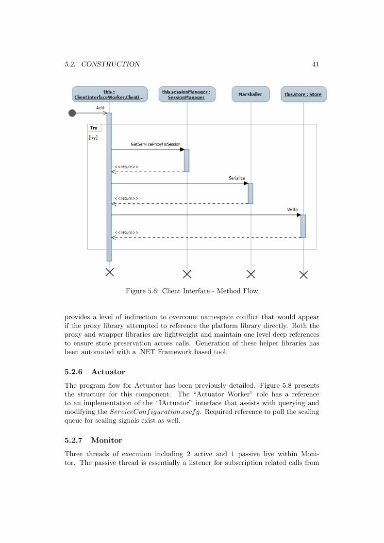
5.2. CONSTRUCTION 41
Figure 5.6: Client Interface - Method Flow
provides a level of indirection to overcome namespace conflict that would appearif the proxy library attempted to reference the platform library directly. Both theproxy and wrapper libraries are lightweight and maintain one level deep referencesto ensure state preservation across calls. Generation of these helper libraries hasbeen automated with a .NET Framework based tool.
5.2.6 Actuator
The program flow for Actuator has been previously detailed. Figure 5.8 presentsthe structure for this component. The “Actuator Worker” role has a referenceto an implementation of the “IActuator” interface that assists with querying andmodifying the ServiceConfiguration.cscfg. Required reference to poll the scalingqueue for scaling signals exist as well.
5.2.7 Monitor
Three threads of execution including 2 active and 1 passive live within Moni-tor. The passive thread is essentially a listener for subscription related calls from

42 CHAPTER 5. IMPLEMENTATION
Figure 5.7: Storage Proxy
Figure 5.8: Actuator - Structure

5.3. ADDITIONS & REFACTORING 43
Figure 5.9: Monitor - Structure
and to Client Interface components. Monitor keeps record of these calls with therecoverySubscribers structure (see Figure 5.9). An active thread is spawned to pollthe registrationQueue for alerts on startup and shutdown of ServiceWrapper roleinstances as shown in Figure 5.10. Instance creations are listed in registeredInstancesstructure and failures are announced if the role instance had previously registeredand proxies have active subscriptions to the role instance.
Lastly, an infinite loop periodically reads measurements for performance coun-ters and ranks instances accordingly, proceeds to compute resource requirementsper the latest readings and sends appropriate scaling signals if required. The mea-surement period is set to coincide with the interval at which performance countersare updated.
5.3 Additions & Refactoring
Framework implementation presented has followed design guidance yet leaves roomfor simple yet important enhancements and improvements.

44 CHAPTER 5. IMPLEMENTATION
Figure 5.10: Monitor - Flow

5.4. TOOLS & TECHNOLOGIES 45
• Support for tenant services utilizing HTTP, though fundamentally embedded,requires trials and verification. This task would also further verify the sessionaffinity functionality provided.
• The Adaptor aspect of an Autonomic System can be realized by ranking andscaling Client Interface components which requires that the subject compo-nent registers with the Monitor and also for Performance Counters measure-ments. Furthermore, multiple Client Interfaces demand externalization of theSessionManager’s logic into a separate component with the necessary inter-face and/or reflecting its state in an Azure Table structure. Modifications de-scribed would ensure correct session affinity for connectionless protocols whereclient requests might be load balanced over Client Interfaces in a Client-ClientInterface affinity less manner.
• Recovery of multiple sessions associated with a particular failed service in-stance is currently performed in a serial fashion and could benefit from aconcurrent approach.
• State storage entries are not deleted when sessions exit for debugging/tracingpurposes and can quite easily be cleaned up for production systems.
5.4 Tools & Technologies
Topics of interest for application development using the Windows Azure platformare briefly covered to provide pointers and clarity on the implementation process.
5.4.1 Windows Azure
“Windows Azure is the operating system that serves as the development, run-time,and control environment for the Windows Azure platform” [30]. Among the servicesoffered are management of application life cycle, resources and load balancing.
5.4.2 Azure SDK
Windows Azure Software Development Kit (SDK)[35] offers tools and resourcesthat aid with preparing (packaging) and deploying Azure applications. The SDKconsists of Windows Azure API binaries, Compute Emulator, Storage Emulatorand a set of command line tools for application packaging and deployment. TheCompute and Storage Emulator allow executing Azure applications in developmentenvironment to ensure correctness of applications flow and data structures beforehosting in production environment.
5.4.3 Microsoft .NET Framework 4.0
“The .NET Framework is an integral Windows component” that provides commonfunctionality for building and running Windows applications [38]. Applications

46 CHAPTER 5. IMPLEMENTATION
developed for Windows Azure can be written using a variety of languages, toolsand frameworks[7] including Microsoft .NET Framework 4.0. C# is a modern andpopular type-safe object-oriented language for writing applications targeting the.NET Framework. The development artifacts discussed in this chapter were createdusing C# and Microsoft .NET Framework 4.0.
5.4.4 Windows Azure Tools for Microsoft Visual Studio
Windows Azure application development is aided by Windows Azure Tools for Vi-sual Studio[45] with source program templates and visual tools for building, debug-ging and deploying web applications and services for Windows Azure.
5.4.5 Windows Azure Platform Management Portal
Customers with Windows Azure subscriptions may administer their account as wellas deploy, manage, and monitor their Windows Azure services via the subject portal.The Service Management API[29] provides a REST interface for automating mostof the management tasks accessible from the management portal.
5.5 Code Metrics Analysis
“Code metrics is a set of software measures that provide developers better insightinto the code they are developing [33].” Microsoft Visual Studio 2010 has built insupport for generating various code metrics. Select Code Metrics for the variousimplementation and test artifacts (Visual Studio Projects) developed as part of thiswork are presented and discussed respectively.
Maintainability Index [37] expresses the ease of code maintenance on a scale of0-100. Index values > 20 are considered to have good maintainability. All Imple-mentation components listed in Table 5.1 carry high index values with the lowestvalues calculated for Client Interface and ServiceWrapper. This indicates the needto revisit these components and consider possible refactoring. Cyclomatic complex-ity is a measure of the structural complexity of the code. Not surprisingly, theMonitor component has the highest complexity value due to the various logicalflows and code paths involved in maintaining rankings, subscriptions and ensuringelasticity. Lastly, Lines of Code (LoC) captures the weight of a component; noticethe heavy weight ClientInterface component which contains significant amount ofsimilar code. These blocks of code can be refactored into appropriate functions orbetter yet auto-generated with a code generation tool.
Code Metrics for Test artifacts developed to conduct experiments against theframework implementation provide interesting information as well as listed in Ta-ble 5.2. All components have similar Maintainability Index with the lowest valuenoted for the CloudExperiements project which contains the actual test scripts.

5.5. CODE METRICS ANALYSIS 47
Project/Package Maintainability Index Cyclomatic Complexity LoC
Actuator 77 70 203CacheAPI 85 16 36
ClientInterface 63 90 322FaultToleranceContract 100 5 0
Monitor 85 193 400OrderService 87 42 108
ServiceWrapper 63 27 72StateStore 88 41 95
StorageInterface 98 3 2Utility 72 33 107
Table 5.1: Implementation Code Metrics Analysis
Project/Package Maintainability Index Cyclomatic Complexity LoC
CloudDeploy 89 50 106CloudExperiments 59 18 93
CloudTest 82 46 124ServiceControl 85 2 5
TestClient 84 3 6TestUtils 72 9 40
Table 5.2: Test Code Metrics Analysis
The highest value for Cyclomatic complexity and LoC expectedly appears for theCloudTest project which orchestrates test execution. CloudDeploy follows with thesecond largest LoC value since it provides the necessary abstractions for managingCloud deployment of the system under test.


Chapter 6
Evaluation
Design and execution of end to end scenarios aimed at making evident the solutionand implementation quality in terms of reliability and scalability is described in thischapter. Statistics gathered are presented and discussed. Each enclosed sectiondescribes the aspect of interest and details the experiment conducted by listingsettings and outcomes.
6.1 Cost
The saying “there is no such thing as a free lunch” holds true for the proposedframework. It is of interest to determine the size of this cost/overhead and its dis-tribution across components. The cost incurred by the implementation is measuredby comparing response times for the Service Wrapper component and the frameworkin general, both in Compute Emulator and on Azure.
Experiment: Measure Framework induced Response Time Overhead
Setup: Execute a simple set of operations {Add, Get, Clear} against aservice hosted independently and when wrapped by the framework.
Method: The operations were executed 1000 times and the measure-ments were averaged.
Results: Range of values for response times gathered from 3 experimen-tal runs are presented in milliseconds (ms), first for Compute Emulatorfollowed by Windows Azure.
Discussion: Response times for the independently hosted service arepresented in Table 6.1 alongside environment specific implicit round-trip latency. Table 6.2 shows response time breakdown for the servicesupported by the implemented framework. The actual response time
49

50 CHAPTER 6. EVALUATION
Environment Service Round-trip Latency
Compute Emulator 13-15 ms 9-11 msWindows Azure 150-180 ms 10-15 ms
Table 6.1: Service Response Time
Environment Service Wrapper Framework Round-trip Latency
Compute Emulator 20-25 ms 80-85 ms 9-11 msWindows Azure 40-70 ms 170-190 ms 10-15 ms
Table 6.2: Service Response Time Breakdown
experienced in this case equals the sum of values for Service Wrapperand Framework column.
The percentage change in response time incurred by framework rangesbetween 633% - 669% for Compute Emulator and between 40% - 45%on Windows Azure. The most probable cause of this marked differenceis the parallel execution of all framework components on a single ma-chine for the Compute Emulator setting. Windows Azure, on the otherhand, assigns separate (virtual) machines for each framework componentwhich only goes to validate the method employed for this experiment.
The response time break down on both environments is expectedly uni-form with Service Wrapper responsible for 20%-25% of the incurred costwhereas the remaining larger slice is introduced by remaining compo-nents including ClientInterface and State Store. The bulk of overheadcan thus be attributed to the functions necessary to ensure messageinterception, logging and forwarding.
6.2 Performance
The implementation under evaluation utilizes (communication, computation andstorage) resources while serving consumers (clients). Desirably, available resourcesshould be put to maximum use and additional provisions should increase through-put. These questions are addressed with the following experiment that aims toinvestigate the correlation of service response time and frequency of refused connec-tions with the number of available Client Interfaces.
Experiment: Vary Count of Available Client Interfaces

6.3. RELIABILITY 51
Setup: Simulate arrival of 10, 100, 500 and 1000 client connections ac-cording to Pareto distribution[6] that perform a basic operation {Add}against the tenant service executing on Compute Emulator. The num-ber of tenant service instances (service wrapper) is fixed at 1.
Method: The Pareto distribution parameter of α and xm are set as 1whereas the parameter x is determined by U(0, 1) - a random variableof uniform distribution.
Results: Framework response times experienced by serviced client pop-ulation were averaged and have been plotted for each population size.The average was calculated discounting unserviced clients, the size ofthat population i.e. the number of connections refused is being plottedas well. The data present is a sample representing implementation be-havior.
Discussion: The collected data provides a number of useful insights.Average response times [Figure 6.1] and number of refused connections[Figure 6.2] suggest efficient usage of available resources. With a sin-gle interface, clients have to queue for service availability which resultsin increase to the response time and in worst case, timeouts. This ef-fect is more visible with larger population where clients may arrive inbatches of various sizes. Addition of client interfaces allows the Cloudload balancer to service clients at alternate interfaces with improvementin response times and reduction in connection refusals.
Also, note that the increase in response times does not notably increasefor most increases in population size and is not linear indicating the abil-ity of the framework to handle spikes of various magnitudes. The settingwhere multiple interfaces share a single endpoint incurs a scheduling sur-charge observable for smaller client populations. Though some varianceexists in the behavior noted for the 3 scenarios, the settings with mul-tiple client interfaces perform better in comparison to the case of singleinterface.
6.3 Reliability
Cloud infrastructure guarantees availability of the specified number and type ofresources. The subject framework benefits from this service as well by modelingits constituent components using available compute and storage resources. Still,beside the tenant service, framework component too may fail. The consequence ofthe various components failures are outlined in the following text.

52 CHAPTER 6. EVALUATION
Figure 6.1: Average Response times for population sizes
Figure 6.2: Connections refused for population sizes

6.3. RELIABILITY 53
6.3.1 Tenant Service Fails
Services hosted within the framework under investigation may be stateless or state-ful. Failure of a stateless service is handled by a combination of the Actuator com-ponent and Cloud infrastructure. The Actuator component preempts acquisition ofresources and delays release which allows for the possibility of sufficient resources athand to process incoming clients. Higher response times or even connections refusalmight be experienced by some clients, however, a complete denial of service is lesslikely to occur. Though Actuator will react to the failure and post a demand foradditional resources, the Cloud Infrastructure too will ensure failed instances arerestarted. Assumptions made regarding Cloud Infrastructure are a given whereascorrectness of Actuator’s function is validated with experiment 6.4.
Stateful services ask more and are provided accordingly. A tenant service exe-cutes within a Cloud “sandbox” which monitors its life cycle and reports a shutdownby placing a message in a queue which is polled by Monitor. Upon reading a failuremessage, all Client Interface components utilizing the failed instance are informedand session recovery is enacted, if required, on healthy and suited tenant serviceinstances. It could be the case that the Client Interface becomes aware of instancefailure when attempting to relay a client request. In this case, the client session isrestored on another service instance and the message relayed thereafter. For bothcases, Client Interface un-subscribes from the failed instance at the Monitor, beforeperforming session recovery, to avoid duplicate failure detection and session recovery.
Being a key scenario, the latter case described has undergone extensive verifi-cation, throughout implementation, during debugging and manual testing sessions.The End to End nature of this Use Case has been addressed with a two prongedapproach. Manual trials performed have shown that failure detection is prompt,owing to multiple detection points, and redo recovery accurate as performed, onlyonce, in concert with Storage Proxy. Related scenario of choosing the healthy in-stance for message replay is verified by section 6.3.2 whereas the quantitative aspectof session recovery involved is investigated in section 6.3.5
6.3.2 Monitor Fails
The Monitor functions to track available instances and their respective loads. Thisinformation is then translated to failure detection, load balancing and elasticity ac-tions. In monitor’s absence, information on the next most available tenant serviceinstance stales whereas failure detection responsibility falls back on the client inter-face component.
Since Monitor presence is ensured by Cloud infrastructure, the effect of temporalmonitor failure (and absence) on response times is of interest and is captured bythe following experiment.

54 CHAPTER 6. EVALUATION
Experiment: Measure ranking validity
Setup: Simulate sequential arrival of clients separated by an interval of250 ms that execute either a basic operation {Add} or more {Add, Get,Clear} against the tenant service hosted on Windows Azure. The num-ber of tenant service instances available behind a single client interfaceis fixed at 3.
Method: Client connection arrival begins after the Monitor builds theinitial ranking and continue till the end of the experiment. During therun, Monitor skips the ranking step for an intermediate period
Results: The response times experienced by batches of 100 clients areaveraged at a number of sample points and plotted.
Discussion: The response times values plotted in Figure 6.3 highlightthe function of the monitor. Do note that the filled data points weretaken during Monitor’s active phase i.e. when the ranking algorithm wassensitive to the changes in load and ranked service wrapper instancesaccordingly, on the other hand, hollow data points mark Monitor’s dor-mant phase.
Interesting observations with regards to data points are at hand: first,positive impact of monitor activity is immediate (data points 0-4) andlasting (5-12). On the other hand, Monitor passivity does not alwayshave a negative impact (7-10). Even though incoming clients convergeon a particular tenant service instance, the performance hit is not worstsince the subject instance is not the least resourced instance. Duringmonitor absence, normal client arrival rates with shorter activities can behandled since no connection refusals were observed, however, surges areunlikely to be addressed. When monitor revives, the ranking resumesto reflect current loads and the response times improve (13-16). Insummary, Monitor serves its function of load distribution in an efficientand resilient manner as signified by the trend line.
6.3.3 Actuator Fails
Actuator is delegated the task of processing scaling signals and effecting elasticity.Monitor pushes resource demand and/or release signals to a queue. In the event ofActuator failure, scaling signals will continue to queue up. An increase in responsetimes or number of refused connections will likely be experienced depending uponthe rate of client arrival, session length and session weight (memory allocated to

6.3. RELIABILITY 55
Figure 6.3: Response time variation
session data). Upon Actuator restart, all signals are read and an accurate pictureof the resource needs or excess is sketched. By balancing elasticity signals of bothscaling up and scaling down that had queued over the period of Actuator absence,a decision is made on whether to scale up or down.
6.3.4 Client Interface Fails
Client Interface expose external endpoint for the framework allowing indirect accessto the tenant service. External clients can only connect to a Client Interface andare not aware of the Service Wrapper endpoints which are internal to the Cloudinfrastructure. Failure of all Client Interface instances will result in denial of service.Beside acting as a load balancing router, the subject component is responsible forsession recovery which increases its significance and the probability of failure in thiscomponent. The component could potentially fail when writing, reading or playingback messages that form part of a session. Thus, multiple instances of the subjectcomponent are recommended to be asked of the Cloud platform to ensure serviceavailability in face of instance failure. Alternatively, Client Interface component canleverage available framework elasticity and robustness functions (see Section 5.3).
6.3.5 Service Recovery
Preservation of stateful interactions in the face of service failures demands the re-covery process to complete, at the least, before the client connection/session timesout. The two step recovery process retrieves the message log for the subject sessionand then plays it back on the chosen healthy instance. The total recovery time canthus be divided into session retrieval and message replay time. Factors that effectthis measurement include the length (number of messages) and weight (message
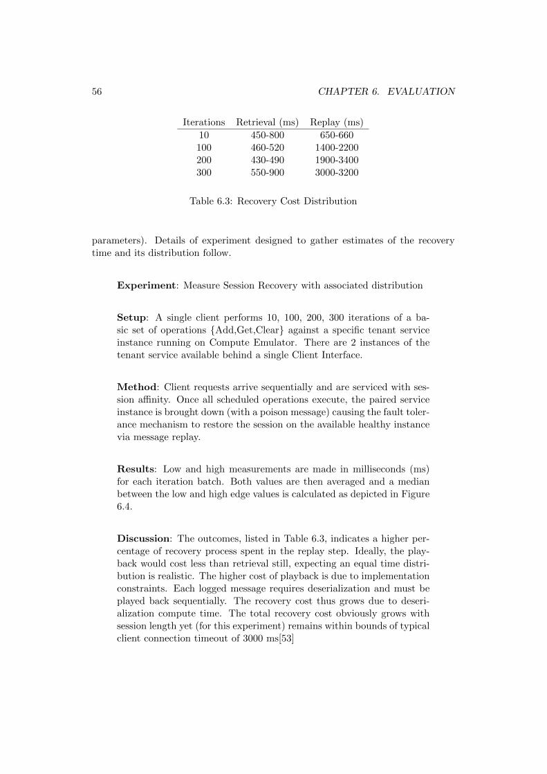
56 CHAPTER 6. EVALUATION
Iterations Retrieval (ms) Replay (ms)
10 450-800 650-660100 460-520 1400-2200200 430-490 1900-3400300 550-900 3000-3200
Table 6.3: Recovery Cost Distribution
parameters). Details of experiment designed to gather estimates of the recoverytime and its distribution follow.
Experiment: Measure Session Recovery with associated distribution
Setup: A single client performs 10, 100, 200, 300 iterations of a ba-sic set of operations {Add,Get,Clear} against a specific tenant serviceinstance running on Compute Emulator. There are 2 instances of thetenant service available behind a single Client Interface.
Method: Client requests arrive sequentially and are serviced with ses-sion affinity. Once all scheduled operations execute, the paired serviceinstance is brought down (with a poison message) causing the fault toler-ance mechanism to restore the session on the available healthy instancevia message replay.
Results: Low and high measurements are made in milliseconds (ms)for each iteration batch. Both values are then averaged and a medianbetween the low and high edge values is calculated as depicted in Figure6.4.
Discussion: The outcomes, listed in Table 6.3, indicates a higher per-centage of recovery process spent in the replay step. Ideally, the play-back would cost less than retrieval still, expecting an equal time distri-bution is realistic. The higher cost of playback is due to implementationconstraints. Each logged message requires deserialization and must beplayed back sequentially. The recovery cost thus grows due to deseri-alization compute time. The total recovery cost obviously grows withsession length yet (for this experiment) remains within bounds of typicalclient connection timeout of 3000 ms[53]

6.4. SCALABILITY 57
Figure 6.4: Recovery cost distribution
6.4 Scalability
Length and number of client sessions are reflected in the volume of state maintainedby the framework. The scalability goal can thus be split into the requirements ofelastic management of session population and their individual state. Section 5.1.3argues for the choice of “Table Service” for realizing a scalable store for sessionstate. Outcomes of experiment on session recovery (presented in section 6.3.5) fur-ther support the validity of design decisions made concerning storage of session logs.The elastic handling of variation in session population thus then need be measuredand analyzed as well.
Experiment: Inspect Scaling Up, Down
Setup: Simulate sequential arrival of clients batches of size 250, sepa-rated by an interval n that execute either a basic operation {Add} ormore {Add, Get, Clear} against the tenant service running in ComputeEmulator. The interval n begins at 500 ms and in 5 iterations shortensto 100 ms to reflect a demand surge. The interval then widens to theinitial value as would be the case in a demand slump. At least 1 tenantservice instances (service wrapper) is always available behind a singleclient interface.
Method: Session creation begins once the Monitor has built the ini-tial ranking and continues till the end of the experiment. Data pointsfor performance counters of interest are collected through the executionwith an interval of 10 ms.

58 CHAPTER 6. EVALUATION
Figure 6.5: Requests / second
Results: Performance counters of Calls/second and % of Processor timeallocated to tenant service are collected and plotted across all instances.
Discussion: The intended surge and slump in service demand is clearfrom the curves in Figure 6.5. The gradual increase in client calls istaken note of and a second instance is brought online well before theactual surge. Note the near uniform distribution of load across availableresources, verifying the sensitivity and accuracy of the ranking proce-dure. The load balanced selection of tenant service instances results insimilar patterns for the percent of processor time allotted to the associ-ated processes as captured in Figure 6.6
Notice the early creation and prolonged availability of the secondary in-stance. The promptness when scaling up ensures timely surge handlingwhereas the delay involved when scaling down allows for coping withinstantaneous increase in service demands. This behavior is only eco-nomical in light of Windows Azure’s billing model (outlined in AppendixA) which charges consumers for 1 compute hour at the minimum.
6.4.1 Elasticity
The notion of an association between % change in two variables is well establishedin the field of economics and is employed to model and reason about relationshipsbetween quantities such a supply, demand and price among others. The Cloud in-centive of on demand scalability obviously carries an economical aspect alongsidereliability and performance dimensions.

6.4. SCALABILITY 59
Figure 6.6: % of Processor Time Alloted
The Midpoint Arc Elasticity method serves as a device to quantify the elasticnature of the relationship between two variables. For two data points of variablesx and y, the following equation computes the extent and nature of (casual) changein x with respect to change in y.
Ex,y = % change in x / % change in y
where % change for a variable n between data points n1 and n0 (noted at timet1 and t0 respectively), is defined as
nchange = (n1 − n0)/((n1 + n0)/2))
Values of >= 1 for Ex,y indicate that x is responsive to changes in y whereaslesser values suggest otherwise. The special case of Ex,y = 1 is termed Unit Elastic.
The earlier described experiment shows how variation in service calls per secondinfluence the % of processor time allotted to service instances. Figure 6.7 plotselasticity values for our sample execution. The curve features a predominantly nearunit elasticity with the occasional spikes which are likely caused by CPU schedul-ing since they occur mostly early in the execution. Leveling these infrequent largevalues is necessary to better understand the elasticity relationship
The spectrum of elasticity measurements can be normalized into unit ( or allpositive) and negative elasticity values where negative values refer to Ex,y < 1 andmay be represented by −1. Higher than unit elasticity values may also be scaleddown to 1 to emphasize the presence of elasticity, not it’s above unit strength.

60 CHAPTER 6. EVALUATION
Figure 6.7: Arc Elasticity
Application of the above scheme results in the curves presented in Figure 6.8which suggests both positive and negative elasticity occurrences. Positive readingsare controlled and are a consequence of load-aware, server-sticky session manage-ment as shown earlier. Negative measurements may register for a number of reasonsincluding creation of majority of shorter sessions requiring no significant increase inprocessor usage and CPU scheduling that retains the higher priority assigned to theservice instance process regardless of the decrease in service calls. The summaryelasticity behavior is expressed by the mode() function which indicates 1 as themost occurring value for all elasticity measurements after the first service call.

6.4. SCALABILITY 61
Figure 6.8: Elastic Execution


Chapter 7
Directions\Future & Related Work
The State abstraction provides a service utilized by stateful services, both immi-grant on-premises application as well as Cloud citizens. There exists motivationfor determining performance benefits of pushing down the state abstraction to theInfrastructure tier. Studies are also in order to compare and improve the varioustechniques employed (e.g. message logs) in light of contemporary and future work.The chapter closes with an overview of related efforts.
7.1 Cloud Integration
Catalog survey of major commercial Cloud platform vendors including AmazonEC2 and Google AppEngine is indicative of presence and ever increasing inclu-sion of autonomic control related primitives. EC2 features CloudWatch[2], AutoScaling[1] and Elastic Loadbalancing[3] services that aim for demand responsive re-source allocation and provisioning. Furthermore, support of memory based cachingin AppEngine provides the foundation for a storage proxy component illustratedhere.
These developments provide confidence in technical soundness and commercialviability of a unified service similar to the State abstraction and framework pre-sented. Integration of such a framework would provide comprehensive out of thebox reliability and elasticity support to developers of existing and new services.
7.2 Tooling
Practicality has required manual configuration of certain aspects of the presentedframework, most visibly, the implementation of the ClientInterface component.Also, familiarity with the Cloud Platform and related development tools is requiredto configure SLO governed bounds on measured performance counters. Code gener-ation tools can automate resolving the former concern whereas a simple managementconsole that functions as a dashboard will resolve the latter. Provision of such tools
63

64 CHAPTER 7. DIRECTIONS\FUTURE & RELATED WORK
will ease migration and maintenance of existing and new services aiming to benefitfrom this work.
7.3 Log Management
As described, session activity is captured in terms of messages sent to the servicefrom client and persistent storage. Both these logs are stored in Azure table storage,a compromise between system memory and disk based storage. The logs are main-tained indefinitely, motivated by the requirement to support recovery of session of avariety of length and the reuse of message logs for session debugging and persistentstorage recovery. Extension of the work here should investigate log trimming tech-niques to reduce its footprint in addition to comparisons of the logging techniquesemployed with alternates described in this text and elsewhere.
7.4 Idempotence
The interplay of ClientProxy and StorageProxy components aided with sessionactivity logs ensures that non-idempotent operations are not repeated during ses-sion recovery. The correctness of this procedure must be validated against and, ifrequired, improved for operations involving time dependent and randomized data.
7.5 Further Tests
Earlier sections have attempted to fairly and sufficiently scrutinize the proposedarchitecture and its implementation. However; given the number of variables in-volved, additional experimentation can provide further insight.
Most importantly, trials should be conducted to determine the performance ofthe StorageProxy under varying loads and the actual cost incurred during recoveryso as to supplement the functional correctness tests already performed.
Moreover, the frequency of various periodic activities performed by frameworkcomponents (e.g. the ranking refresh interval observed by the monitor) has remainedfix for all experiments reported. Tests should be conducted to surface their optimalvalues and how they relate to various key performance indicators such as service re-sponse time and efficient resource usage (for instance, should the ranking frequencyincrease and decrease proportionally to the rate of change in performance countermeasurements). Control exerting properties can then be surfaced (with tooling) toallow runtime (automated) framework management.

7.6. R.A.I.N-FALL 65
7.6 R.A.I.N-fall
The business case for Cloud ERP presented in this work and elsewhere[49] focuseson opportunities of elasticity and flexibility inherent to Cloud Computing and pos-sibilities to overcome migration, security, legal, SLA and of course State concerns.Investigation into applicability of the R.A.I.N criteria to the question of Cloud ERPadoption would further support its relevance to Cloud Services in general.
7.7 Related Work
Privacy and legal requirements as well as increased communication latency andcosts have been identified as major impediments which must be addressed to realizea full Cloud embrace[19]. Partial and constrained deployment of ERP applicationsover a hybrid infrastructure spanning across private and public infrastructure canaid with mitigating Cloud adoption risks. The proposed approach models a legacyERP deployment as a graph “G” where application components (i.e. presentation,business logic, storage tier) and internal and external users denote nodes on “G”and an edge represents a communication link. Policy “P” is defined to constrain acomponent’s location (public or local infrastructure). Various hybrid arrangementsof G under P are then considered to identify the most cost effective scheme withregard to private and public compute, storage and communication costs.
Re-engineering is one path towards adapting legacy applications for trendy ar-chitectures. Since Cloud computing erects a platform that spans all layers of anapplication’s execution environment, research has thus focused on revising specificaspects of an application. The study reported in [57] presents an ontology based ap-proach for re-engineering ERP applications for Cloud platforms. Focus is placed ona 2 tier design that is supported by an object relational mapping (ORM) framework.Various existing tools are utilized to create an enterprise ontology that integratesindividual ontologies extracted from code classes and database schema where theORM ontology is used to bridge semantic relations. Ontology partitioning tech-niques based on weighted graphs are applied to the Enterprise Ontology to surfacecandidate Cloud services. The approach presented appears narrow and fragile as aspecific application architecture is assumed, and does not apply in absence of a welldefined mapping between code and database concepts. Moreover, Cloud elementsof elasticity and billing are not taken into account.
Complete overhaul of existing business applications for Cloud platform remainsan option as well. Such radical transformation is the subject of the work presentedby [50]. Existing automation of business processes is viewed from various perspec-tives including hierarchical, behavioral, information flow and resource oriented. Itis assumed that Cloud Business Processes will be realized with Cloud Business Ser-vices that utilize underlying Cloud Services. Existing list of perspectives is thus

66 CHAPTER 7. DIRECTIONS\FUTURE & RELATED WORK
extended for Cloud Business Services to include 3 additional perspectives of func-tional, non-functional and management (meta-service) nature. Thus, it is arguedthat existing business processes may be migrated to Cloud by choreographing avail-able Cloud Business Services with well defined perspectives (contracts) of the latterkind.
Benefits of elastic resources have been made accessible to execution of businessprocesses expressed in BPEL with the architecture described in [15]. The solutioncomprises of components that perform functions of service discovery, load analysisand scheduled resource provisioning to effect load balanced and elastic enactment ofCloud business processes. BPEL construct of (dynamic) partnerLink is capitalizedon realize on-the-fly selection of a target Cloud business service (host) to perform agiven business process step. The system aims for a decoupled design to support va-riety of Cloud providers, resource allocation policies and business service registries.Concerns of failure and recovery are however not touched upon.
Employment of autonomic computing concepts by the work presented here isaware of existing efforts including that of an integrated approach [56] towards re-source consumption and allocation management. In that scheme, a nested controlloop attempts first to improve resource usage by executing middleware providedmanagement functions and failing that resorts to provisioning of resources whichare gradually but shortly reclaimed after performance improves. Algorithms at workhere are rather sophisticated and passive making them less responsive in comparisonto our simple and preemptive yet cautious approach.
Decentralized autonomic control for guaranteed Quality of Service is utilized bythe work reported in [4] which utilizes Peer to Peer protocols to establish a connectedserver cluster. Each and every cluster node provides a single and the same serviceand in addition runs membership and routing algorithms. The solution presentedprovides a static node connectivity parameter that need be balanced to reduce bothsystem size and average delay. Moreover, the routing mechanism employed doesnot make allowance for server affinity.

Chapter 8
Revision
This chapter reviews the work performed by recalling the identified requirementsand continues to present the solution outline as well as measurement findings.
8.1 Requirements Revisited
Attractive research questions surfaced when ERP challenge landscape met CloudComputing opportunity horizon. Ties between Cloud adoption and adaption moti-vated investigation into the State abstraction - a reliable and elastic state manage-ment framework. Problem domain analysis produced necessary and comprehensiveguidance on Cloud fitness criteria (R.A.I.N) and design alternatives of server andclient side state preservation. With due deliberation, concepts from AutonomicComputing and of Replay Recovery were favored as solution foundations.
8.2 Solution Brief
Properties of state preservation, fault tolerance and elasticity, all with Cloud ground-ing, were uniquely designated to the solution and inspired definition of architecturalcomponents including Client and Storage Proxy, Actuator, Monitor and State Ser-vice. Completeness was exhibited with a mapping between designated propertiesand interplay of identified components. Candidate Use Cases of state management,elasticity and fault tolerance were supported with algorithms governing state preser-vation, recovery, load balancing, elasticity and actuation.
Established solution architecture underwent design where questions regardingappropriate infrastructure, necessary data structures and correct control flow wereanswered. Products of ensuing construction have been illustrated with figures anddescriptions. Remarks on further additions and technologies employed were alsomade.
67
68 CHAPTER 8. REVISION
8.3 Measurement Observations
Analysis of trial outcomes indicated acceptably low cost on part of the frameworkthus supporting adoption. Performance experiments conducted showed efficient re-source usage. Furthermore, the function of the Monitor component proved efficientand robust. On the other hand, failure of Actuator will result in only eventualyet correct scaling. Caution was recorded when employing a single Client Interfacethough improvement opportunities are at hand here as well as in the case of recov-ery cost particularly message replay. Sensitivity was noted for load balancing andtimeliness for elasticity. More specifically, unit elastic behavior between demand(service calls) and supply (CPU allocation) has been reported.
Identified opportunities for future work include infrastructure support for theproposed framework, supporting tooling, better log management and further tests.Remarks on related work are also presented as end note.
8.4 Conclusion
Preceding narrative finds origin in questions deliberated at ACME Nordic regardingCloud deployment of TERP, their ERP solution. This work took the approach ofgeneralizing the specific problem in terms of the State abstraction. Ensuing stepsresulted in a proof-of-concept implementation of State as a Service supported withsolid theoretical foundations and layers of experimental evidence. Avenues of im-provement concerning log management and performance enhancements remain openfor further investigation.
Findings reported by this work bear testimony to the significant and wide spreadutility of facilities that simplify adapting Stateful Services to the Stateless Cloudenvironment. Future offering and support of functionality similar to the State ab-straction from Cloud platform and tool vendors will further attest this thesis.

Appendix A
Windows Azure Billing Model
Basic understanding of the pricing scheme associated with Windows Azure is usefulfor rationalizing the behavior embedded in Algorithm 5 presented in Chapter 5 andevaluated in Chapter 8.
Windows Azure usage charges for consumption of compute, storage and band-width resources are incurred according to either a subscription or Pay-As-You-Go(PAYg) model[8]. The subscription model offers a defined limit on monthly re-source usage and available services for a fixed fee. In contrast, for PAYg, Computecosts are calculated at an hourly rate where partial hours are charged as full hours.Storage charges depend upon on the number of gigabytes used and the number oftransactions executed. Data transfer prices are affected by geographical location ofthe host data center and service clients. Generally, transfers between data centersand client premises are charged for, transfers within the same data center are not.
69


Bibliography
[1] Amazon auto scaling, http://aws.amazon.com/elasticloadbalancing/ - accessedJanuary 23 2012.
[2] Amazon cloudwatch, http://aws.amazon.com/cloudwatch/ - accessed January23 2012.
[3] Amazon elastic loadbalancing, http://aws.amazon.com/elasticloadbalancing/ -accessed January 23 2012.
[4] Constantin Adam and Rolf Stadler, Adaptable server clusters with qos objec-tives, Integrated Network Management, 2005, pp. 149–162.
[5] Amazon, Amazon elastic compute cloud,http://aws.amazon.com/ec2/ - accessed January 23 2012.
[6] Barry C. Arnold, Pareto distributions, International Cooperative PublishingHouse.
[7] Windows Azure, Developer center,http://www.windowsazure.com/en-us/develop/net - accessed January 23 2012.
[8] , Windows azure pricing,http://www.microsoft.com/windowsazure/pricing/ - accessed January 23 2012.
[9] Roger Barga, David Lomet, Thomas Baby, and Sanjay Agrawal, Persistentclient-server database sessions, Advances in Database Technology - EDBT2000, Lecture Notes in Computer Science, vol. 1777, Springer Berlin / Hei-delberg, 2000, pp. 462–477.
[10] Roger Barga, David Lomet, Stelios Paparizos, Haifeng Yu, and Sirish Chan-drasekaran, Persistent applications via automatic recovery, Database Engineer-ing and Applications Symposium, International (2003), 258.
[11] Brad Calder and Andrew Edwards, Windows azure drive,http://go.microsoft.com/?linkid=9710117 - accessed January 23 2012, Febru-ary 2010.
71

72 BIBLIOGRAPHY
[12] David Chappell, Introducing the windows azure platform, http:
//www.davidchappell.com/writing/white_papers/Introducing_the_
Windows_Azure_Platform,_v1.4--Chappell.pdf - accessed January 232012.
[13] , Introducing windows azure, http://www.davidchappell.com/
writing/white_papers/Introducing_Windows_Azure,_v1.3--Chappell.
pdf - accessed January 23 2012.
[14] Thomas Dreibholz, An efficient approach for state sharing in server pools, InProceedings of the 27th IEEE Local Computer Networks Conference, 2002,pp. 348–352.
[15] Tim Drnemann, Ernst Juhnke, and Bernd Freisleben, On-demand resourceprovisioning for bpel workflows using amazon’s elastic compute cloud, ClusterComputing and the Grid, 2009, pp. 140–147.
[16] Borko Furht and Armando Escalante, Handbook of cloud computing, SpringerUS, 2010.
[17] Google, Google app engine,http://code.google.com/appengine/ - accessed January 23 2012.
[18] S. Hadjiefthymiades, Drakoulis Martakos, and Costas Petrou, State manage-ment in www database applications, Proceedings of the 22nd International Com-puter Software and Applications Conference, COMPSAC ’98, 1998, pp. 442–448.
[19] Mohammad Y. Hajjat, Xin Sun, Yu-Wei Eric Sung, David A. Maltz, Sanjay G.Rao, Kunwadee Sripanidkulchai, and Mohit Tawarmalani, Cloudward bound:planning for beneficial migration of enterprise applications to the cloud, ACMSIGCOMM Conference, 2010, pp. 243–254.
[20] IBM, Websphere cast iron cloud integration, http://www-01.ibm.com/software/integration/cast-iron-cloud-integration/ - accessedJanuary 23 2012.
[21] Dr. Charles B. Kreitzberg and Ambrose Little, The power of personas,http://msdn.microsoft.com/en-us/magazine/dd569755.aspx - accessed Febru-ary 14 2012.
[22] Horacio Andres Lagar-Cavilla, Joseph Andrew Whitney, Adin Matthew Scan-nell, Philip Patchin, Stephen M. Rumble, Eyal de Lara, Michael Brudno, andMahadev Satyanarayanan, Snowflock: rapid virtual machine cloning for cloudcomputing, Proceedings of the 4th ACM European conference on Computersystems, EuroSys ’09, 2009, pp. 1–12.

BIBLIOGRAPHY 73
[23] Tim Landgrave, Server-side state management for .net architects,http://www.builderau.com.au/program/windows/soa/Server-side-state-management-for-NET-architects/0,339024644,320273014,00.htm - accessedAugust 6 2010.
[24] Orion Letizi, Stateful web applications that scale like stateless ones,http://drdobbs.com/tools/208403462 - accessed January 21 2012.
[25] Ang Li, Xiaowei Yang, Srikanth Kandula, and Ming Zhang, Cloudcmp: compar-ing public cloud providers, Internet Measurement Conference, 2010, pp. 1–14.
[26] B.C. Ling and A. Fox, A self-tuning, self-protecting, self-healing session statemanagement layer, Autonomic Computing Workshop, 2003, june, pp. 131 –139.
[27] Peter Mell and Timothy Grance, Nist definition of cloud computing, TheNational Institute of Standards and Technology (NIST), U.S. Department ofCommerce.http://csrc.nist.gov/publications/nistpubs/800-145/SP800-145.pdf
- accessed February 9 2012.
[28] Microsoft, Visual studio 2010 products,http://www.microsoft.com/visualstudio/en-us/products/2010-editions - ac-cessed February 13 2012.
[29] MSDN, About the service management api,http://msdn.microsoft.com/en-us/library/ee460807.aspx - accessed January 232012.
[30] , About windows azure,http://msdn.microsoft.com/en-us/library/dd179442.aspx - accessed January23 2012.
[31] , Appfabric service bus,http://msdn.microsoft.com/en-us/library/ee732537.aspx - accessed April 192011.
[32] , Blob service api,http://msdn.microsoft.com/en-us/library/dd135733.aspx - accessed January23 2012.
[33] , Code metrics values,http://msdn.microsoft.com/en-us/library/bb385914.aspx - accessed January23 2012.
[34] , Deploying a windows azure service,http://msdn.microsoft.com/en-us/library/windowsazure/gg433027.aspx - ac-cessed January 23 2012.

74 BIBLIOGRAPHY
[35] , Developing applications for windows azure,http://msdn.microsoft.com/en-us/library/gg433098.aspx - accessed January23 2012.
[36] , Linq,http://msdn.microsoft.com/en-us/netframework/aa904594.aspx - accessedApril 21 2011.
[37] , Maintainability index range and meaning,http://blogs.msdn.com/b/codeanalysis/archive/2007/11/20/maintainability-index-range-and-meaning.aspx - accessed January 22 2012.
[38] , .net framework conceptual overview,http://msdn.microsoft.com/en-us/library/zw4w595w.aspx - accessed January22 2012.
[39] , Overview of creating a hosted service for windows azure,http://msdn.microsoft.com/en-us/library/gg432976.aspx - accessed January23 2012.
[40] , Queue service api,http://msdn.microsoft.com/en-us/library/dd179363.aspx - accessed January23 2012.
[41] , Real world: Startup lifecycle of a windows azure role,http://msdn.microsoft.com/en-us/library/hh127476.aspx - accessed January23 2012.
[42] , Sql azure,http://msdn.microsoft.com/library/ee336279.aspx - accessed January 22 2012.
[43] , Table service api,http://msdn.microsoft.com/en-us/library/dd179423.aspx - accessed January23 2012.
[44] , Windows azure platform training course,http://msdn.microsoft.com/en-us/gg271268 - accessed April 21 2011.
[45] , Windows azure tools for microsoft visual studio,http://msdn.microsoft.com/en-us/library/ee405484.aspx - accessed January 232012.
[46] OCCI, Open cloud computing interface, http://occi-wg.org/ - accessed January23 2012.
[47] David Oppenheimer, Archana Ganapathi, and David A. Patterson, Why dointernet services fail, and what can be done about it?, Proceedings of the 4thconference on USENIX Symposium on Internet Technologies and Systems -Volume 4, 2003, pp. 1–1.

BIBLIOGRAPHY 75
[48] The Register, Meta cloud,http://www.theregister.co.uk/2009/02/24/the meta cloud/ - accessed August16 2011.
[49] Imran Saeed, Gustaf Juell-Skielse, and Elin Uppstrm, Cloud enterprise resourceplanning adoption:motives & barriers, Fifth International Conference on Re-search and Practical Issues of Enterprise Information Systems (confenis2011),2011.
[50] Rainer Schmidt, Perspectives for moving business processes into the cloud, En-terprise, Business-Process and Information Systems Modeling, vol. 50, SpringerBerlin Heidelberg, 2010, pp. 49–61.
[51] Bogdan Solomon, Dan Ionescu, Marin Litoiu, and Gabriel Iszlai, Designingautonomic management systems for cloud computing, 2010 International JointConference on Computational Cybernetics and Technical Informatics (2010),631–636.
[52] Xiang Song, Namgeun Jeong, Phillip W. Hutto, Umakishore Ramachandran,and James M. Rehg, State management of web services, (2004), Proceedings ofthe 10th IEEE Workshop on Future Trends of Distributed Computing System.
[53] Microsoft Support, How to modify the tcp/ip maximum retransmission timeout,http://support.microsoft.com/kb/170359 - accessed April 18 2011.
[54] Yong Xie and Yong-Meng Teo, State management issues and grid services, Gridand Cooperative Computing - GCC 2004, Lecture Notes in Computer Science,vol. 3251, Springer Berlin / Heidelberg, 2004, pp. 17–25.
[55] Christos A. Yfoulis and Anastasios Gounaris, Honoring slas on cloud computingservices: a control perspective, In European Control Conference , ECC09, 2009.
[56] Ying Zhang, Gang Huang, Xuanzhe Liu, and Hong Mei, Integrating resourceconsumption and allocation for infrastructure resources on-demand, CloudComputing (CLOUD), 2010 IEEE 3rd International Conference on, 2010,pp. 75 –82.
[57] Hong Zhou, Hongji Yang, and Andrew Hugill, An ontology-based approach toreengineering enterprise software for cloud computing, Computer Software andApplications Conference, Annual International (2010), 383–388.


www.kth.se
TRITA-ICT-EX-2012:31