state & activity diagram © copyright 2001 snu oopsla lab
TRANSCRIPT

State & Activity Diagram
© copyright 2001 SNU OOPSLA Lab.

Contents – Part1. State Diagram Basic State Machine Concepts Statecharts and Objects Advanced Modeling Concepts Case Study

Next slides are… Basic State Machine Concepts Statecharts and Objects Advanced Modeling Concepts Case Study

ONONONON
Automata A machine whose output behavior is not only a direct
consequence of the current input, but of some past history of its inputs
Characterized by an internal state which represents this past experience
ONONONONONONONON ONONONON
OFFOFFOFFOFF

off
on
State Machine (Automaton) Diagram
Graphical rendering of automata behavior
Lamp OnLamp OnLamp OnLamp On
Lamp OffLamp OffLamp OffLamp Off
off
on

Outputs and Actions As the automaton changes state it can
generate outputs:on
off
Lamp OnLamp Onprint(”on”)print(”on”)Lamp OnLamp Onprint(”on”)print(”on”)
Lamp Lamp OffOff
Lamp Lamp OffOff
off
on
Moore automaton
on
off
Lamp OnLamp OnLamp OnLamp On
Lamp Lamp OffOff
Lamp Lamp OffOff
off
on/print(”on”)print(”on”)
Mealy automaton

Extended State Machines Addition of variables (“extended state”)
off
on
Lamp OnLamp OnLamp OnLamp On
Lamp OffLamp OffLamp OffLamp Off
off
on/ctr := ctr + 1
ctr : Integerctr : Integerctr : Integerctr : Integer

A Bit of Theory An extended (Mealy) state machine is defined by:
a set of input signals (input alphabet) a set of output signals (output alphabet) a set of states a set of transitions
triggering signal action
a set of extended state variables an initial state designation a set of final states (if terminating automaton)
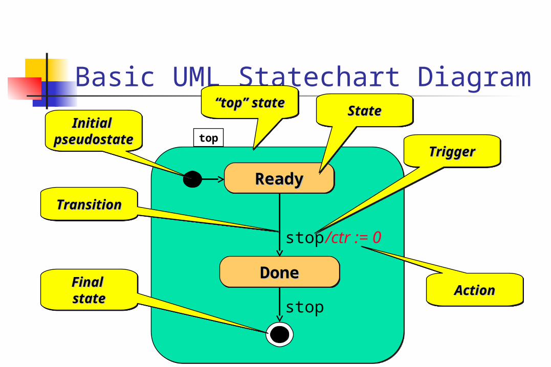
top
Basic UML Statechart Diagram
ReadyReadyReadyReady
stop
/ctr := 0stop
StateStateStateState
TriggerTriggerTriggerTrigger
ActionActionActionAction
Initial Initial pseudostatepseudostate
Initial Initial pseudostatepseudostate
TransitionTransitionTransitionTransition
Final Final statestateFinal Final statestate
DoneDoneDoneDone
““top” statetop” state““top” statetop” state

What Kind of Behavior? In general, state machines are suitable for
describing event-driven, discrete behavior inappropriate for modeling continuous behavior
timetime
thresholdthreshold

Event-Driven Behavior Event = a type of observable occurrence
interactions: synchronous object operation invocation (call event) asynchronous signal reception (signal event)
occurrence of time instants (time event) interval expiry calendar/clock time
change in value of some entity (change event) Event Instance = an instance of an event (type)
occurs at a particular time instant and has no duration

The Behavior of What? In principle, anything that manifests event-driven
behavior NB: there is no support currently in UML for modeling
continuous behavior In practice:
the behavior of individual objects object interactions
The dynamic semantics of UML state machines are currently mainly specified for the case of active objects

Next slides are… Basic State Machine Concepts Statecharts and Objects Advanced Modeling Concepts Case Study
Statecharts UML uses an object-oriented variant of Harel’s
statecharts adjusted to software modeling needs
Used to model event-driven (reactive) behavior well-suited to the server model inherent in the object paradigm
Primary use for modeling the behavior of active event-driven objects
systems modeled as networks of collaborating state machines run-to-completion paradigm significantly simplifies concurrency
management

Statecharts (cont’d) Includes a number of sophisticated features that
realize common state-machine usage patterns: entry/exit actions state activities dynamic and static conditional branching
Also, provides hierarchical modeling for dealing with very complex systems
hierarchical states hierarchical transitions orthogonality

What is a State A state diagram may have a starting point (solid
circle) and several end points (bull’s eyes). A state is shown as a rounded rectangle. Each state has a name, optionally state
variables (i.e., attributes of the state-owning class), and optionally activities.
Standard events in the activity compartment include entry, exit, and do.
Name
Statevariables
Activities

State Transition Transitions between states are shown as arrows. Fork and
join using the synch. bar are allowed. A transition can be labeled with an event that causes it.
When an event occurs, the transition from one state to another fires.
If no event is specified, the transition will fire when internal actions of the source state are executed.

State Transition Syntax:
event-name ( parameters ) [guard condition] / action expressions An event can be one of the following cases:
A message is received from another object (or the object itself) A specified time has passed; e.g., after(2 seconds) There has been a change in some state; e.g., when(quantity <
10) When a guard condition is specified, the event must occur and
the condition be true for the transition to fire. Action expressions are written in terms of operations and
attributes of the owning class (the classifier) and/or with parameters of the event.
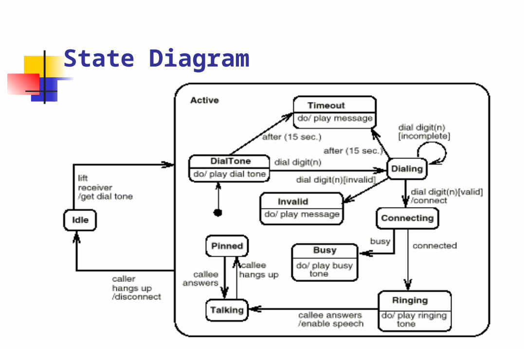
State Diagram
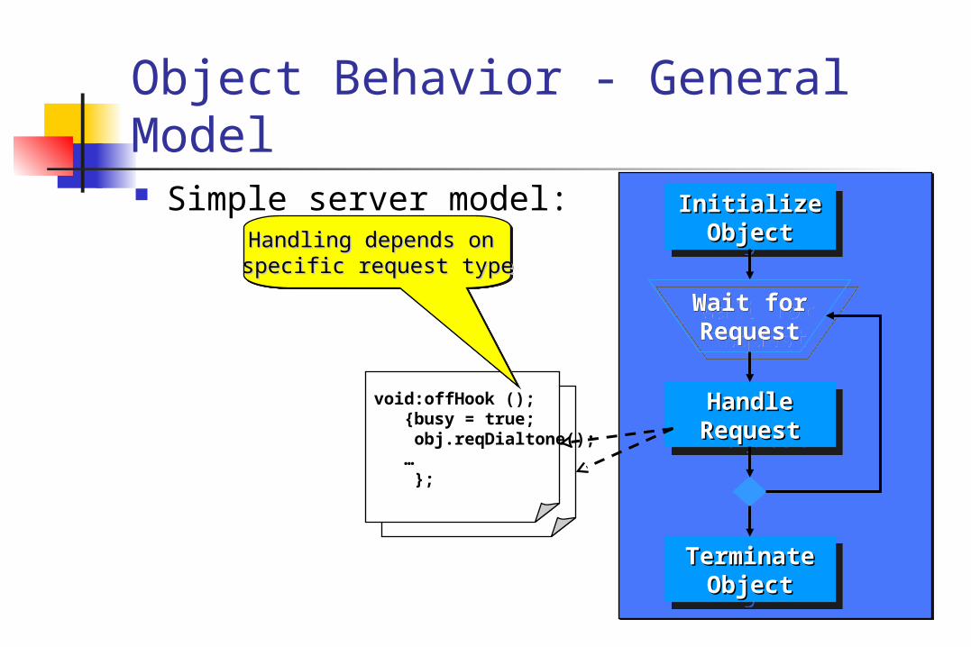
Object Behavior - General Model Simple server model:
HandleHandleRequestRequest
HandleHandleRequestRequest
InitializeInitializeObjectObject
InitializeInitializeObjectObject
TerminateTerminateObjectObject
TerminateTerminateObjectObject
Wait forWait forRequestRequest
Wait forWait forRequestRequest
void:offHook (); {busy = true; obj.reqDialtone(); … };
Handling depends on Handling depends on specific request typespecific request type
Handling depends on Handling depends on specific request typespecific request type

Direct mapping:
HandleHandleEventEvent
InitializeInitializeObjectObject
TerminateTerminateObjectObject
Wait forWait forEventEvent
on
off
Lamp OnLamp OnLamp OnLamp On
Lamp Lamp OffOff
Lamp Lamp OffOff
off
on/print(”on”)
stop
Object Behavior and State Machines

HandleHandleRequestRequest
HandleHandleRequestRequest
InitializeInitializeObjectObject
InitializeInitializeObjectObject
TerminateTerminateObjectObject
TerminateTerminateObjectObject
Wait forWait forRequestRequest
Wait forWait forRequestRequest
HandleHandleRequestRequest
HandleHandleRequestRequest
InitializeInitializeObjectObject
InitializeInitializeObjectObject
TerminateTerminateObjectObject
TerminateTerminateObjectObject
Wait forWait forRequestRequest
Wait forWait forRequestRequest
Object and Threads• Passive objects: depend on external power (thread of execution)• Active objects: self-powered (own thread of execution)
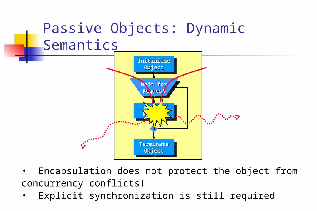
Passive Objects: Dynamic Semantics
• Encapsulation does not protect the object from concurrency conflicts!• Explicit synchronization is still required
HandleHandleRequestRequest
HandleHandleRequestRequest
InitializeInitializeObjectObject
InitializeInitializeObjectObject
TerminateTerminateObjectObject
TerminateTerminateObjectObject
Wait forWait forRequestRequest
Wait forWait forRequestRequest

anActiveObjectanActiveObject
##currentEvent : EventcurrentEvent : Event
+ + start ( )start ( )+ poll ( )+ poll ( )+ stop ( )+ stop ( )
Active Objects and State Machines Objects that encapsulate own thread of
execution
created
ready
start/^master.ready()
poll/^master.ack()
stop/
poll/defer
ready
created
start start/^master.ready() ready

Active Objects: Dynamic Semantics
Run-to-completion model: •serialized event handling •eliminates internal concurrency•minimal context switching overhead
ActiveObject:

Active1Active1Active1Active1 Active2Active2Active2Active2
The Run-to-Completion Model A high priority event for (another) active object will
preempt an active object that is handling a low-priority event
hi
hi
lo
Next slides are …
Basic State Machine Concepts Statecharts and Objects Advanced Modeling Concepts Case Study

State Entry and Exit Actions A dynamic assertion mechanism
LampOnLampOnLampOnLampOn
entry/lamp.on();
exit/lamp.off();
e1e1
e2e2

Resulting action sequence:Resulting action sequence:printf(“exiting”);printf(“exiting”);printf(“to off”);printf(“to off”);lamp.off();lamp.off();
Resulting action sequence:Resulting action sequence:printf(“exiting”);printf(“exiting”);printf(“to off”);printf(“to off”);lamp.off();lamp.off();
Order of Actions: Simple Case Exit actions prefix transition actions Entry action postfix transition actions
printf(“exiting”);printf(“exiting”);printf(“needless”);printf(“needless”);lamp.off();lamp.off();
printf(“exiting”);printf(“exiting”);printf(“needless”);printf(“needless”);lamp.off();lamp.off();
off/printf(“needless”);off/printf(“needless”);
off/printf(“to off”);off/printf(“to off”);LampOffLampOffLampOffLampOff
entry/lamp.off();entry/lamp.off();
exit/printf(“exiting”);exit/printf(“exiting”);
LampOnLampOnLampOnLampOn
entry/lamp.on();entry/lamp.on();
exit/printf(“exiting”);exit/printf(“exiting”);
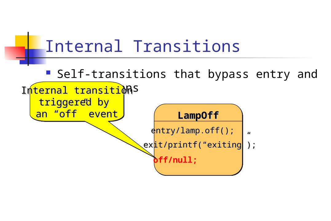
Internal Transitions Self-transitions that bypass entry and exit
actions
LampOffLampOffLampOffLampOff
entry/lamp.off();entry/lamp.off();
exit/printf(“exiting”);exit/printf(“exiting”);
off/null;
Internal transitionInternal transitiontriggered by triggered by an “off” eventan “off” event
Internal transitionInternal transitiontriggered by triggered by an “off” eventan “off” event

ErrorErrorErrorError
entry/printf(“error!”)entry/printf(“error!”)
State (“Do”) Activities Forks a concurrent thread that executes until:
the action completes or the state is exited through an outgoing transition
do/while (true) alarm.ring();
““do” activitydo” activity““do” activitydo” activity

Guards Conditional execution of transitions
guards (Boolean predicates) must be side-effect free
SellingSellingSellingSelling
UnhappyUnhappyUnhappyUnhappy
HappyHappyHappyHappy
bid bid [(value >= 100) & (value < 200)] /sell/sell
bidbid [value >= 200] /sell/sell
bidbid [value < 100] /reject/reject

Static Conditional Branching Merely a graphical shortcut for convenient
rendering of decision trees
[(value >= 100) & (value < 200)] /sell/sell
[value >= 200] /sell/sell
[value < 100] /reject/reject
SellingSellingSellingSelling
UnhappyUnhappyUnhappyUnhappy
HappyHappyHappyHappy
bidbid

bid /gain := calculatePotentialGain(value)
SellingSellingSellingSelling
UnhappyUnhappyUnhappyUnhappy
HappyHappyHappyHappy
Dynamic Conditional Branching Choice pseudostate: guards are evaluated at the
instant when the decision point is reached
[(gain >= 100) & (gain < 200)] /sell/sell
[gain >= 200] /sell/sell
[gain < 100] /reject/reject
DynamicDynamicchoicepointchoicepointDynamicDynamic
choicepointchoicepoint

Hierarchical State Machines Graduated attack on complexity
states decomposed into state machines
LampFlashingLampFlashingLampFlashingLampFlashingflashflash//
11sec/sec/11sec/sec/
FlashOffFlashOffFlashOffFlashOff
entry/lamp.off()entry/lamp.off()
FlashOnFlashOnFlashOnFlashOn
entry/lamp.on()entry/lamp.on()offoff//
LampOffLampOffLampOffLampOff
entry/lamp.off()entry/lamp.off()
LampOnLampOnLampOnLampOn
entry/lamp.on()entry/lamp.on()
onon//
onon//onon//

“Stub” Notation Notational shortcut: no semantic significance
LampFlashingLampFlashingLampFlashingLampFlashingflashflash//
onon//
FlashOnFlashOn
FlashOffFlashOff
offoff//
LampOffLampOffLampOffLampOff
entry/lamp.off()entry/lamp.off()
LampOnLampOnLampOnLampOn
entry/lamp.on()entry/lamp.on()
on/on/ onon//

LampFlashingLampFlashingLampFlashingLampFlashing
11sec/sec/11sec/sec/
FlashOffFlashOffFlashOffFlashOff
entry/lamp.off()entry/lamp.off()
FlashOnFlashOnFlashOnFlashOn
entry/lamp.on()entry/lamp.on()offoff//
LampOffLampOffLampOffLampOff
entry/lamp.off()entry/lamp.off()
LampOnLampOnLampOnLampOn
entry/lamp.on()entry/lamp.on()
onon//
Group Transitions Higher-level transitions
flashflash//
onon//
Default transition toDefault transition tothe initial pseudostatethe initial pseudostateDefault transition toDefault transition to
the initial pseudostatethe initial pseudostate
Group transitionGroup transitionGroup transitionGroup transition

Completion Transitions Triggered by a completion event
generated automatically when an immediately nested state machine terminates
CommittingCommittingCommittingCommitting
Phase1Phase1Phase1Phase1
Phase2Phase2Phase2Phase2CommitDoneCommitDoneCommitDoneCommitDone
completion completion transition (no trigger)transition (no trigger)
completion completion transition (no trigger)transition (no trigger)

LampFlashingLampFlashingLampFlashingLampFlashing
off/off/
FlashOffFlashOffFlashOffFlashOff
FlashOnFlashOnFlashOnFlashOn
Triggering Rules Two or more transitions may have the same event
trigger innermost transition takes precedence event is discarded whether or not it triggers a transition
on/
on/

Deferred Events Events can be retained if they do not trigger
a transition
off/off/
LampOnLampOnLampOnLampOn
entry/lamp.on()entry/lamp.on()
on/on/
LampOffLampOffLampOffLampOff
entry/lamp.off()entry/lamp.off()
off/deferoff/defer
Deferred eventDeferred eventDeferred eventDeferred event
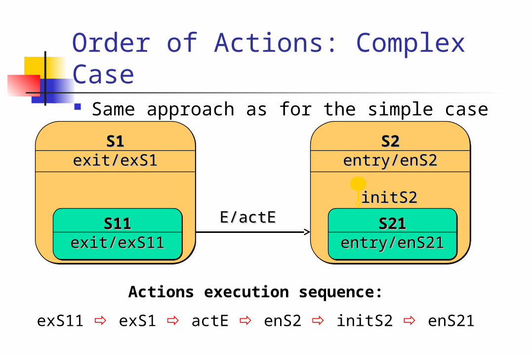
Order of Actions: Complex Case Same approach as for the simple case
S1S1exit/exS1exit/exS1
S1S1exit/exS1exit/exS1
S11S11exit/exS11exit/exS11
S11S11exit/exS11exit/exS11
S2S2entry/enS2entry/enS2
S2S2entry/enS2entry/enS2
S21S21entry/enS21entry/enS21
S21S21entry/enS21entry/enS21
initS2initS2E/actEE/actE
Actions execution sequence:
exS11 exS1 actE enS2 initS2 enS21

suspend/suspend/
History Return to a previously visited hierarchical state
deep and shallow history options
DiagnosingDiagnosingDiagnosingDiagnosing
Diagnostic1Diagnostic1Diagnostic1Diagnostic1
Step11Step11Step11Step11
Step12Step12Step12Step12
Diagnostic2Diagnostic2Diagnostic2Diagnostic2
Step21Step21Step21Step21
Step22Step22Step22Step22resume/resume/H*H*H*H*

Orthogonality Multiple simultaneous perspectives on the same
entity
ChildChild
AdultAdult
RetireeRetiree
ageage
PoorPoor
RichRich
financialStatusfinancialStatus

Orthogonal Regions Combine multiple simultaneous descriptions
ChildChild
AdultAdult
RetireeRetiree
ageage
PoorPoor
RichRich
financialStatusfinancialStatus
PoorPoor
RichRich
financialStatusfinancialStatus
ChildChild
AdultAdult
RetireeRetiree
ageage

OutlawOutlawOutlawOutlaw
LawAbidingLawAbidingLawAbidingLawAbiding PoorPoorPoorPoor
RichRichRichRich
financialStatusfinancialStatuslegalStatuslegalStatus
Orthogonal Regions - Semantics All mutually orthogonal regions detect the same
events and respond to them “simultaneously” usually reduces to interleaving of some kind
robBank/robBank/ robBank/robBank/

Catch22Catch22Catch22Catch22
sanityStatussanityStatus flightStatusflightStatus
Interactions Between Regions Typically through shared variables or awareness of
other regions’ state changes
((flying)/flying)/
CrazyCrazyentry/sane := false;entry/sane := false;
CrazyCrazyentry/sane := false;entry/sane := false;
SaneSaneentry/sane := true;entry/sane := true;
SaneSaneentry/sane := true;entry/sane := true;
requestrequestGrounding/Grounding/
FlyingFlyingentry/flying := true;entry/flying := true;
FlyingFlyingentry/flying := true;entry/flying := true;
GroundedGroundedentry/flying := false;entry/flying := false;
GroundedGroundedentry/flying := false;entry/flying := false;
((sane)/sane)/
(~(~sane)/sane)/
sane : Booleansane : Booleansane : Booleansane : Boolean
flying : Booleanflying : Booleanflying : Booleanflying : Boolean

Transition Forks and Joins For transitions into/out of orthogonal regions:
StaffStaffMemberMember
StaffStaffMemberMember
employeeemployee
ChildChildChildChild AdultAdultAdultAdult RetireeRetireeRetireeRetiree
ageage
ManagerManagerManagerManager

Common Misuse of Orthogonality Using regions to model independent objects
ChildChild
AdultAdult
RetireeRetiree
ChildChild
AdultAdult
RetireeRetiree
Person1Person1 Person2Person2
Person1Person1 Person2Person2

Next slides are … Basic State Machine Concepts Statecharts and Objects Advanced Modeling Concepts Case Study

line card 1line card 1
line card Nline card NEnd userEnd user
unreliable telecom lines
Case Study: Protocol Handler A multi-line packet switch that uses the
alternating-bit protocol as its link protocol
SWITCHSWITCH
.
.
.
ABsender
ABreceiver
End user
End user
ABsender
ABreceiver
AB protocolAB protocolAB protocolAB protocol

packetizer unpackerReceiverSender
Alternating Bit Protocol (1) A simple one-way point-to-point packet protocol
data(1)
ackA
pktAdata(1)
ack
ack
data(2)
ackB
pktBdata(2)
ack
ack
…etc.
AB protocolAB protocolAB protocolAB protocol

Alternating Bit Protocol (2) State machine specification
ackB/^ackdata/^pktA
ackA/^ack data/^pktB
timeout/^pktB
timeout/^pktA
Sender SM
AcceptPktA
WaitAckA
AcceptPktB
WaitAckB
pktA/^dataack/^ackA
pktB/^dataack/^ackB
timeout/^ackB
timeout/^ackA
RcvdPktA
WaitPktB
RcvdPktB
WaitPktA
Receiver SM

Additional Considerations Support (control) infrastructure
SWITCHSWITCH
ABABreceiverreceiver
ABABsendersender
operatoroperatorinterfaceinterface
DBDBinterfaceinterface
SystemSystemoperatoroperator
DBaseDBase
AB linesAB linesmanagermanager
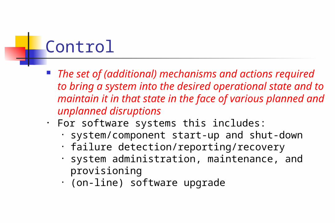
Control The set of (additional) mechanisms and actions
required to bring a system into the desired operational state and to maintain it in that state in the face of various planned and unplanned disruptions
• For software systems this includes:• system/component start-up and shut-down• failure detection/reporting/recovery• system administration, maintenance, and
provisioning• (on-line) software upgrade

Retrofitting Control Behavior
AcceptPktA
WaitAckA
AcceptPktB
WaitAckB
Failed
JustCreated HardwareAudit
GettingData
ReadyToGo
AnalysingFailure

The Control Automaton In isolation, the same control behavior appears much
simpler
Failed
JustCreated
HardwareAudit
GettingData
ReadyToGo
AnalysingFailure
OperationalOperational

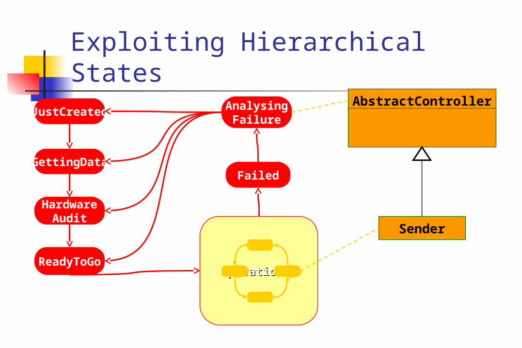
Exploiting Inheritance Abstract control classes can capture the
common control behavior
AbstractController
Sender Receiver . . .
Failed
JustCreated
HardwareAudit
GettingData
ReadyToGo
AnalysingFailure
OperationalOperational
Exploiting Hierarchical StatesAbstractController
Sender

Activity Diagrams

Activity Diagram Applications Intended for applications that need control flow or
object/data flow models … ... rather than event-driven models like state
machines. For example: business process modeling and
workflow. The difference in the three models is how step in a
process is initiated, especially with respect to how the step gets its inputs.

Control Flow Each step is taken when the previous one finishes … …regardless of whether inputs are available,
accurate, or complete (“pull”). Emphasis is on order in which steps are taken.
Not UMLNotation! Chart CourseChart Course Cancel TripCancel Trip
Analyze Weather InfoAnalyze Weather Info
Weather InfoStart

Object/Data Flow Each step is taken when all the required input objects/data are
available … … and only when all the inputs are available (“push”). Emphasis is on objects flowing between steps.
Design ProductDesign Product
ProcureMaterials
ProcureMaterials
Acquire CapitalAcquire Capital
BuildSubassembly 1
BuildSubassembly 1
BuildSubassembly 2
BuildSubassembly 2
FinalAssembly
FinalAssembly
Not UMLNotation

State Machine Each step is taken when events are detected by
the machine … … using inputs given by the event. Emphasis is on reacting to environment.
Ready To StartReady To Start
Coin Deposited
Ready For OrderReady For OrderSelection Made
DispenseProduct
DispenseProduct
ReturnChange
ReturnChange
Cancel Button Pressed
Not UMLNotation

Currently activity graphs are modeled as a kind of state machine.
Modeler doesn't normally need to be aware of this sleight-of-hand ...
... but will notice that "state" is used in the element names.
Activity graphs will become independent of state machines in UML 2.0.
Activity Diagrams Based on State Machines

Just like their state machine counterparts (simple state and submachine state) except that ...
... transitions coming out of them are taken when the step is finished, rather than being triggered by a external event, ...
... and they support dynamic concurrency.
Action Action (State)
Subactivity Subactivity (State)
Kinds of Steps in Activity Diagrams

Action (State)
An action is used for anything that does not directly start another activity graph, like invoking an operation on an object, or running a user-specified action.
However, an action can invoke an operation that has another activity graph as a method (possible polymorphism).
Action

Subactivity (State)
A subactivity (state) starts another activity graph without using an operation.
Used for functional decomposition, non-polymorphic applications, like many workflow systems.
The invoked activity graph can be used by many subactivity states.
Subactivity

Example
POEmployee.sortMail Deliver Mail
POEmployee
sortMail() Check OutTruck
Put MailIn Boxes
Deliver Mail

POEmployee
sortMail()
Activity Graph as Method
Application is completely OO when all action states invoke operations
All activity graphs are methods for operations.
POEmployee.sortMail POEmployee.deliverMail
deliverMail()«realize»
Check OutTruck
Put MailIn Boxes
PO Employee Deliver Mail Method

Dynamic concurrency Applies to actions and subactivities. Not inherited from state machines. Invokes an action or subactivity any number of times in
parallel, as determined by an expression evaluated at runtime. Expression also determines arguments.
Upper right-hand corner shows a multiplicity restricting the number of parallel invocations.
Outgoing transition triggered when all invocations are done. Currently no standard notation for concurrency expression
or how arguments are accessed by actions. Attach a note as workaround for expression. Issue for UML 2.0.
Action/Subactivity *

Object Flow (State)
A special sort of step (state) that represents the availability of a particular kind of object, perhaps in a particular state.
No action or subactivity is invoked and control passes immediately to the next step (state).
Places constraints on input and output parameters of steps before and after it.
Class[State]

Object Flow (State)
Take Order must have an output parameter giving an order, or one of its subtypes.
Fill Order must have an input parameter taking an order, or one of its supertypes.
Dashed lines used with object flow have the same semantics as any other state transition.
Order[Taken]
Take Order Fill Order

Coordinating Steps
Initial state
Final state
Fork and join
Inherited from state machines

Decision point and merge ( ) are inherited from state machines.
For modeling conventional flow chart decisions.
Coordinating Steps
CalculateCost
ChargeAccount
GetAuthorization
[cost < $50]
[cost >= $50]

Synch state ( ) is inherited from state machines but used mostly in activity graphs.
Provides communication capability between parallel processes.
Coordinating Steps
State machinenotation
InspectInstall
Foundation
BuildFrame
InstallElectricity
in Foundation
PutOn
Roof
InstallElectricityIn Frame
InstallElectricityOutside
InstallWalls
* *

Forks and joins do not require composite states. Synch states may be omitted for the common case
(unlimited bound and one incoming and outgoing transition).
BuildFrame
InstallFoundation
InstallElectricity
in Foundation
PutOn
Roof
InstallElectricityIn Frame
InstallElectricityOutside
InstallWalls
Inspect
Activity diagramnotation
Convenience Features (Synch State)

Object flow states can be synch states
O bj[S2]
A11 A12 A13
A21 A22 A23
Convenience Features (Synch State)

Convenience Features Fork transitions can have guards.
RegisterBug
EvaluateImpact
FixBug
RevisePlan
ReleaseFix
TestFix
[ priority = 1]
RegisterBug
EvaluateImpact
FixBug
RevisePlan
ReleaseFix
TestFix
[ priority = 1]
[else]
Instead of doing this:

Convenience Features Partitions are a grouping mechanism. Swimlanes are the notation for partitions. They do not provide domain-specific semantics. Tools can generate swimlane presentation from domain-
specific information without partitions.
RegisterBug
EvaluateImpact
FixBug
RevisePlan
ReleaseFix
TestFix
[ priority = 1]
Management
Support
Engineering

Convenience Features Signal send icon
Signal
CoffeePot
Wake Up
Get Cups
Turn on Coffee Pot
Coffee Done
Drink Coffee
Signal
… translates to a transition with a send action.
Signal receipt icon
… translates to a wait state (a state with no action and a signal trigger event).

When to Use Activity Diagrams Use activity diagrams when the behavior
you are modeling ... does not depend much on external events. mostly has steps that run to completion, rather
than being interrupted by events. requires object/data flow between steps. is being constructed at a stage when you are more
concerned with which activities happen, rather than which objects are responsible for them (except partitions possibly).

Activity Diagram Modeling Tips Control flow and object flow are not separate.
Both are modeled with state transitions. Dashed object flow lines are also control flow. You can mix state machine and control/object
flow constructs on the same diagram (though you probably do not want to).

Activity Diagram Modeling Tips
RequestReturn
Get ReturnNumber
Ship Item
Item[returned]
ReceiveItem
RestockItem
CreditAccount
Item[available]
Customer Telesales WarehouseAccounting
From UML User Guide:

Act
ivit
y M
odelin
g T
ips
RequestReturn
Get ReturnNumber
Ship Item
Item[returned]
ReceiveItem
RestockItem
CreditAccount Item
[available]
Customer Telesales WarehouseAccounting

Activity Diagram Modeling Tips Activity diagrams inherit from state machines the
requirement for well-structured nesting of composite states.
This means you should either model as if composite states were there by matching all forks/decisions with a correspond join/merges …
… or check that the diagram can be translated to one that is well-nested.
This insures that diagram is executable under state machine semantics.

Activity Diagram Modeling TipsWell-nested:

Not well-nested:
Activity Diagram Modeling Tips
Apply structured coding principles. (Be careful with goto’s!)

Activity Diagram Modeling TipsCan be translated to well-nesteddiagram on earlier slide:

Example : Login of an online banking system

Activitydiagram
withdraw money(ATM)

Wrap Up: Activity Diagrams Use Activity Diagrams for applications that are primarily
control and data-driven, like business modeling … … rather than event-driven applications like embedded
systems. Activity diagrams are a kind of state machine until UML 2.0
… … so control and object/data flow do not have separate
semantics. UML 1.3 has new features for business modeling that
increase power and convenience. Check it out and give feedback!