starting a wave structure interaction cfd simulation …
TRANSCRIPT
6th European Conference on Computational Mechanics (ECCM 6)7th European Conference on Computational Fluid Dynamics (ECFD 7)
1115 June 2018, Glasgow, UK
STARTING A WAVE STRUCTURE INTERACTION CFDSIMULATION FROM AN ADVANCE TIME: HOT-START
MUSIEDLAK P.-H.1, RANSLEY E.1, BROWN S.A.1, CHILD B.F.M.2,HANN M.1, IGLESIAS G.1 AND GREAVES D.1
1 School of Engineering, Plymouth UniversityReynolds Building, Drakes Circus, PL4 8AA Plymouth, United Kingdom
2 DNV-GLOne Linear Park, Avon Street, Bristol BS2 0PS, United kingdom
Key words: Hot-start, CFD, wave-structure interaction, Mesh-deformation, Coupling
Abstract. This paper details the reduction of an OpenFOAM CFD WSI simulation toits major event, by starting it at an advance time: a new procedure named hot-start,which is a first step towards a future coupling development. The investigations concernthe fluid flow and a structure motion hot-start, taken separately, and are restricted tonumerical comparison. Four design waves based upon the NewWave theory are simulatedwith increasing starting times - where the wave field is initialized as the sum of thelinear components of the considered wave - and compare to conventional ones - which areinitialized with still water. The structure motion hot-start is assessed using a heave decaytest: a conventional heave decay simulation is compared against several ones where themotion, velocity and acceleration of the structure are assigned for several time-steps. Aninitial mesh-deformation library is specifically created to assign the structure at the hot-start position by incrementally deforming the mesh towards the right structure position.Independent to the non-linearity of the case, a start 4 s prior to the main event is found tobe enough to accurately represent the wave field. The motion of the structure was foundto require at least 5 time-steps in order to converge to the reference one. Those resultsaim to be usable for other CFD WSI applications.
1 INTRODUCTION
Numerical modelling is widely used in offshore and coastal engineering to assess wave-structure interaction (WSI) since it gives increased understanding of processes such as:the evolution of the coast line; the manoeuvrability of ships; the mechanical design offloating oil and gas platforms; or of wind turbines. Many offshore standards are basedupon numerical modelling, and often adapted with the experience gathered by successand failures. Marine Renewable Energy (MRE) developers use the offshore oil and gasindustry standards. But, nowadays the numerous failures of the different MRE devices

MUSIEDLAK P.-H., RANSLEY E., BROWN S.A., CHILD B.F.M., HANN M., IGLESIAS G. ANDGREAVES D.
has proven those standards to be misfits to the sector [1]. Often a MRE - especially WaveEnergy Converters (WEC) - device motion needs to be accentuated to generate power [2],unlike traditional oil and gas floating structure which are designed to controlled and limittheir motion. Hence, this dynamic behaviour of MRE devices requires models which arecapable of accurately simulating large motions. Also, a MRE device is often composedof multiple components which interact with each other, resulting in complex, and oftenhighly non-linear, device motion which depends heavily on past events [3].
Therefore, these industries require a more complex numerical model which is able toassess such levels of physical complexity. Computational Fluid Dynamics (CFD) simula-tions solve the full Navier-Stokes equations with limited simplifications. Their use as adesign tool is growing in several industries, where the offshore industry starts to recognizetheir reliability compare to empirical methods use in industry standards. But this in-crease in complexity induces an increase - sometimes drastic - in Central Processing Unit(CPU) effort. This is a major issue if such methods want to be utilized in routine designprocesses [1], since it limits the use of CFD to very case specific physics representation,or research bases cases.
In WSI, CFD simulations are mainly used for mechanical design of extreme loads.Typically, the engineering method uses a design wave, which hits the structure, henceallowing prediction of the loads. Using a Numerical Wave Tank (NWT) starting fromstill water, the CFD simulation generates the wave at the inlet, and then propagates ittowards the outlet. The period of time necessary to create the wave from still water isrequired to build-up of fully non-linear fluid flow. This is the common set-up of a WSICFD simulation: a similar example to this study is the WEC developer Carnegie whosimulated in a NWT, the dynamic response of their device under extreme events usingthe NewWave description, where the simulations started from still water [4].
However, the main interest of a WSI simulation is the impact of the wave on thestructure, rather than the propagation of the wave itself, and this constitutes only asmall amount of the full CFD simulation. Therefore, this paper presents a novel approachthat limits WSI CFD simulations to the times of interest: the simulation will start slightlybefore the impact - this strategy is termed ’hot-start’. It is expected to result in significantCPU savings without substantially compromising the accuracy of the results. In thecase of use for WSI problems, and to maintain the accuracy of the results, a hot-startedsimulation requires consideration two mains issues (taken separately in this study): 1) thewave field reproduction, and; 2) the hot-start assignment of the motion of the structure.
This study is a first step in the development of a coupling between an industry standardsbased numerical model - WaveDyn, developed by DNV-GL in Bristol UK , and the open-source, CFD code OpenFOAM. To maximize efficiency, the coupling strategy utilises thecomputationally efficient method, WaveDyn, preferentially reserving the expensive NSsolver for instances in which the linear assumptions of WaveDyn are violated [5]. Thecoupling strategy is outside of the scope of this paper. This study focuses on the achievingthe hot-start for a CFD simulation in a purely numerical approach. No comparison withexperimental data will be conducted. The study objective is to prove the feasibility of aCFD hot-start for the wave field, and for a rigid body motion.
2
MUSIEDLAK P.-H., RANSLEY E., BROWN S.A., CHILD B.F.M., HANN M., IGLESIAS G. ANDGREAVES D.
2 METHODOLOGY
2.1 Initial conditions for the wave field variables
The objective of the following method is to be able to accurately hot-start a 2D wave-only simulation using a design wave. It aims to be adaptable for other wave design.Investigations are compared against CFD simulations using the usual strategy, i.e. start-ing from still water at time t = 0.
2.1.1 The reference NWT and design wave set-up
Design waves are typically used to assess the survivability of a structure in extremewave events, [4], [2]. They aim to generate the maximum loads the structure would beexposed to during its design lifetime. This engineering method has been subjected todebate: indeed, for structures subject to large motions, more extreme loads can be foundoutside the scope of this extreme representation depending on the historic of the devicemotion [6]. But, this method is still widely used, and is used in this study.
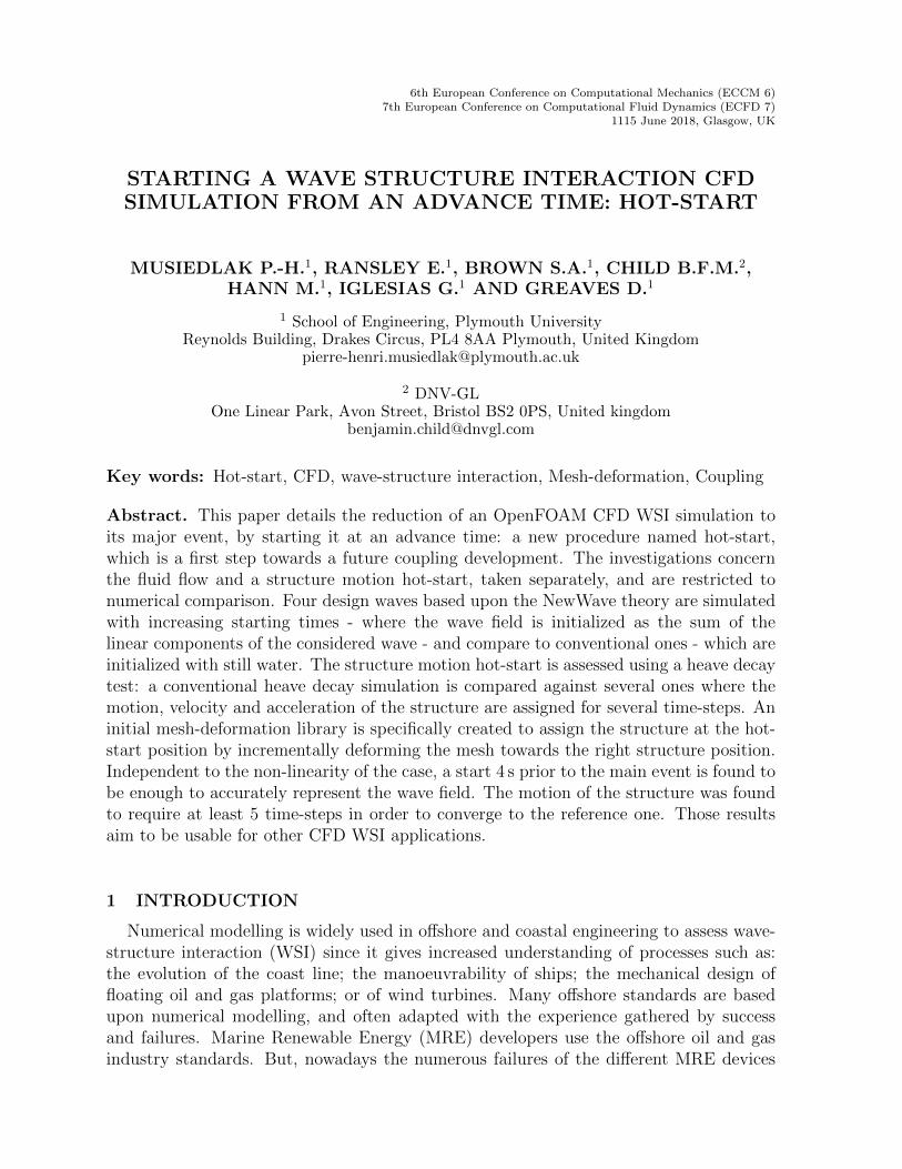
This study uses a Pierson-Moskowitz spectrum from a 100 year storm hindcast dataobtained at the Wave Hub site (Tz = 14 s , Hs = 4.4 m, [7]). The design wave is definedusing the NewWave [8] wave representation, which produces, for a given sea-state, theaverage shape of the highest wave with a specified exceedance probability [9]. This shapeis a focus event which occurs at a specific position in time and space, as shown in Figure1a. The mathematical description at first order is defined by a sum of linear waves; thusit is easy to implement at the NWT inlet. Four NewWave type focus events of increasingsteepness are obtained from this hindcast [6].
(a) Theoretical shape of the surface-elevation ofa NewWave event at focus location, generatedby a Pierson-Moskowitz spectrum
(b) A schematic representation of the 2D-NWT:1 is the inlet; 2 is the working region; and 3 isthe relaxation zone
(c) The domain is a 20 × 0.1 × 4 m cuboid con-sisting of cubic background of 6 cells per meter,refined to level 3 around the mean-water line
Figure 1: The reference design wave and the 2D-NWT set-up
The four focus event are reproduced in the 2 dimensional (2D) NWT represented in
3

MUSIEDLAK P.-H., RANSLEY E., BROWN S.A., CHILD B.F.M., HANN M., IGLESIAS G. ANDGREAVES D.
Figure 1b, which dimensions are based upon a previous study [10]. The waves2Foamlibrary is used for the wave generation and absorption methods [11]. The wave is generatedat the inlet, which is the region number 1 in Figure 1b. At the inlet, a superposition oflinear wave components, obtained using a Fast Fourier Transform (FFT) of the experimentwave gauge located the furthest upstream, is used to generate the wave. The componentsare selected by incrementally adding waves in order of magnitude (largest first) until auser prescribed precision is achieved [5]. This optimization of the selection of the numberof components was found to save Random Access Memory (RAM) and CPU effort [12].The wave then propagates in a fully non-linear manner along the NWT in the workingregion, which is the region number 2 in Figure 1b. The outlet, or relaxation zone, isthe region 3 in Figure 1b, where the wave is absorbed. To assure the fully non-linearpropagation of the four waves cases, the reference CFD simulations are starting from stillwater at time t = 0; the conventional CFD set-up.
The 2D-NWT mesh shown in Figure 1c is generated using the commands blockMeshand snappyHexMesh. The background mesh is made of 6 square cells per meter, assquare meshes were found to converge more rapidly than one of increasing ratios [2], andto more accurately reproduce the physics. This background mesh is then refined threetimes using the octree refinement strategy [13] around the mean water line along the fulllength of the tank (as simulations were found to be slower and different from a fully squaremesh if a shorter refinement region was used).
The experimental equivalent position of the structure (here the X-MED buoy [6]) isconsidered as the focus space location, abscissa x = 5.58 m. The focus time, tfocus, ischosen as the time where the highest surface-elevation is observed at this location. Theflow field characteristics are measured at this position: the surface-elevation as a functionof time; the water velocities and pressure along the water-column. The surface elevationis measured during the simulation by the library waveGaugesNProbes [11]. The velocityand pressure at time t = tfocus along the water column are post-processed using Paraviewby slicing the domain at the structure position, and then extracting the two profiles.
2.1.2 Method
A hot-start CFD NWT set-up only differs from a conventional one by its starting time,thot, and the initial set-up of the wave fields. The wave field is described at the inlet bythe same sum of linear components in both cases, but for a hot-start simulation becausethe starting time is different than 0, the description applies to the full NWT length at thehot-start time, thot. Therefore, compare to a conventional CFD simulation where the fluidhas been propagating in a fully non-linear manner across the NWT until the hot-starttime, a hot-started simulation at this starting time, i.e. thot, will lack in accuracy.
But the differences are expected to reduce as the two simulations run, as the hot-started simulation build-up to a fully non-linear description. In other words, in orderto reproduce a non-linear event, it is expected that a period of time is required for ahot-started simulation to converge to the reference one. So, the time of the focus extremeevent is considered as the location in time where the simulation needs to be hot-started:
4

MUSIEDLAK P.-H., RANSLEY E., BROWN S.A., CHILD B.F.M., HANN M., IGLESIAS G. ANDGREAVES D.
tfocus = thot. Additionally, a period of time, tminus, is subtracted to the hot-start timeso that the hot-started simulation can build up to the solution. It is required that thisparameter is smaller than the hot-start time; otherwise the conventional CFD set-upwould be used.
Therefore, the method consists of running hot-started simulations with increasingtminus, from 0 to thot. As tminus increases, the hot-started simulation have more timeto build up towards the reference one, and by comparing the reproduction of the focusevent, a convergence is expected. The surface elevation, velocity and pressure fields pre-dicted by the hot-started simulations are benchmarked against the predictions from thereference simulation, which used the conventional setup. To investigate the dependencyof the hot-start with the non-linearity of the event, the four focus event of increasingsteepness are used. The convergence of the hot-started simulation are expected to bedepend on the non-linearity of the case.
2.2 Positioning the structure and assigning initial motion state
In this second sub-section, the study focuses on the hot-start for a rigid-body only,trying to avoid the influence of the fluid. Its objective is to accurately hot-start a 3Dsimulation involving a simple motion of a rigid-body to provide the proof of the hot-startconcept for WSI applications.
2.2.1 The initial mesh deformation - deformDyMMesh
As the structure position at the hot-start is supposed to be known, the usual approachis to generate a new mesh with the up-to-date geometry file (.stl using a Computer AidedDesign software (CAD)) from this new position. The final mesh is undeformed, and anynew deformation due to the movement of the structure, will deform the mesh. Also, ifthe hot-start position is different from the structure’s equilibrium, the deformation ofthe mesh will increase as the structure returns to its equilibrium. This might led toa mesh of lower quality at the equilibrium which can generate some instabilities. Thispre-process step can be quite time-consuming, and, in the future use of this study fora software coupling, the structure position could be different for each simulated cases.And, this would require to generate a different geometry file each time, or to make thisautomatically, which means another coupling process with the CAD software.
This study uses a new approach, where only the mesh with its structure at equilibriumis first needed. By deforming this mesh, the structure is moved to its position at theinitial hot-start time. One advantage of this method is that only one geometry model isrequired, and that any structure position can be obtained simply be deforming the mesh.
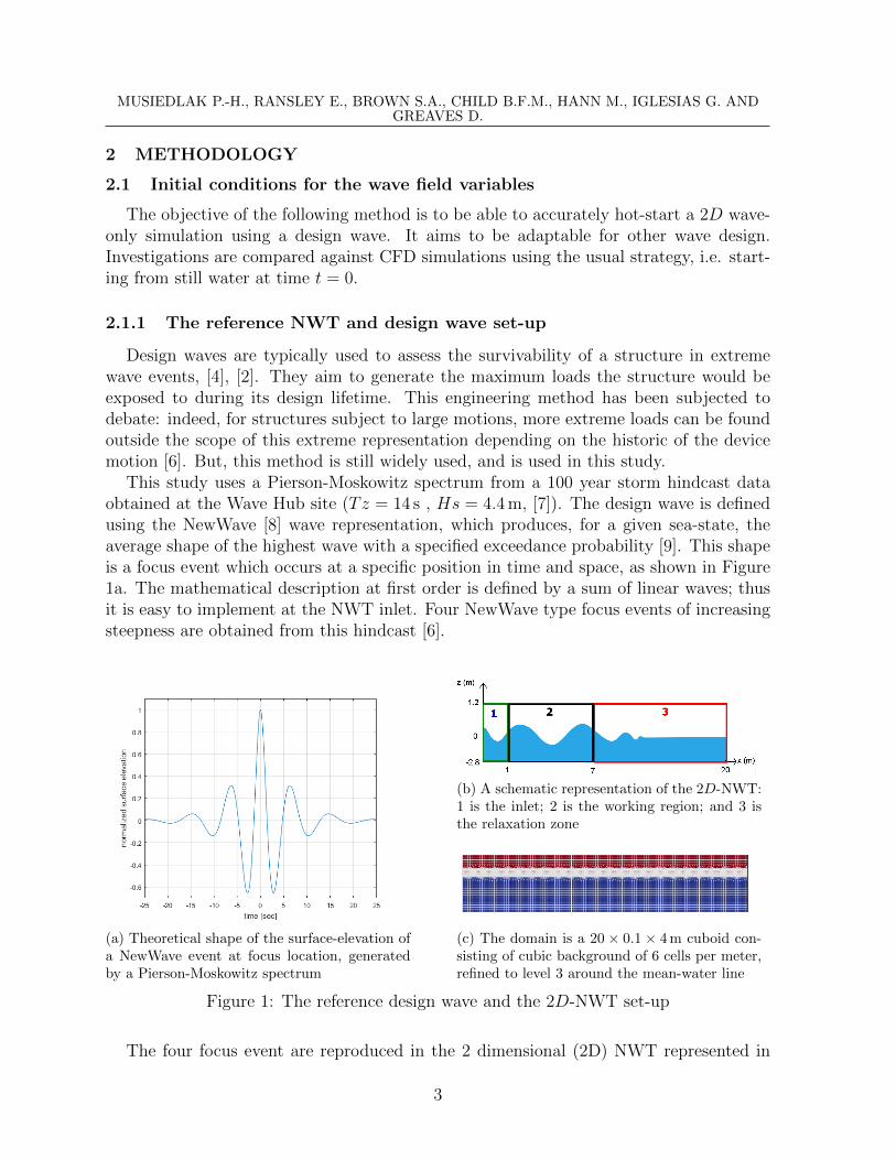
For this purpose, a new library was created based on the waveDyMFoam solver andthe rigidBodyDynamics library from OpenFOAM-4.1; named deformDyMMesh. Usingas input an offset from the structure position and a number of iterations, it moves thestructure by the amount defined by the amplitude of the offset divided by the numberof iterations. The mesh is then updated, and this results in a new deformed mesh. Byrepeating this process the number of iterations, the structure ends at the wanted the
5
MUSIEDLAK P.-H., RANSLEY E., BROWN S.A., CHILD B.F.M., HANN M., IGLESIAS G. ANDGREAVES D.
(a) Original mesh (b) Half-deformed mesh (c) Mesh fully deformed
Figure 2: Steps of the deformDyMMesh use
position, and the mesh is deformed accordingly. The larger the offset, the more iterationsare required to ensure the mesh quality of each iteration. A poor mesh quality results oftenin squeezed cells, and an inability of using the deformed mesh for any further simulations.
An example of the capacity of this library is shown in Figure 2, where a struc-ture, here the X-MED buoy [6], is successfully moved from its initial position using thedeformDyMMesh library, and that it results in a deformed mesh of quality.
The hardware used for this study is the Viglen Genie computer, equipped with IntelXeon E5-1680 v4 at 3.40 GHz with 16 processors, where the 64 version of Ubuntu isdirectly installed. All the commands are run in serial mode.
The execution of the original mesh in Figure 2a takes 14 s for this hardware: blockMeshof a 1.5 × 1.5 × 2 m box with 6 cells per meter, refined to level 3 between [−0.25; 0.25],and to level 4 at the structure surface; a total of 160306 cells. The deformation donein this example moves the structure by: 0.06 m in surge, 0.14 m in heave, a 10 degreeangle in pitch, and none in sway, roll and yaw. Depending on the number of iterationrequired for the deformation, deformDyMMesh takes between 50 s for 50 iterations, anddrops to 10.2 s for 15 iterations, which is the minimum number of iterations found for thisamplitude of deformation for this case.However the proven quality of the mesh generated by the deformDyMMesh library, noproof of its ability not to influence the results has been done so far.
2.2.2 Proof of use of deformDyMMesh
To prove the use of this library, a heave decay test is performed. The simulationreference is carried out using a geometry file updated according to the heave decay releaseposition to insure the initial mesh to be undeformed. And, it is opposed to a simulationstarting with a mesh deformed by the deformDymMesh library from the structure atits equilibrium position to the release position. The flow fields are set as still water. Nohot-start are considered here, and the structure used for the proof of deformDyMMeshis the X-MED buoy, which has no velocity nor acceleration set at the starting time for
6

MUSIEDLAK P.-H., RANSLEY E., BROWN S.A., CHILD B.F.M., HANN M., IGLESIAS G. ANDGREAVES D.
both cases.
(a) The case using deformDyMMesh with acut at the mean water line at time t = 0 s
(b) The heave displacement of a conven-tional simulation compared to one usingdeformDyMMesh library
Figure 3: A decay test to prove the use of the deformDyMMesh library
Figure 3b shows the results of the simulations by comparing the two structures heavedisplacement as an offset from the structure equilibrium position. Very slight differencesare found before time t = 6 s. And, those are expected to be due to the small differ-ence in the initial flow fields as the deformed mesh generates small circular like waves,which can be seen in Figure 3b. After time t = 6 s, the small are growing due to theradiated waves generated by the structure motion and reflecting on the walls. But, thosedifferences are considered as negligible, where the circular waves and the slight differencesare expected to be sensitive to the heave decay test only. Therefore, this proves the useof the deformDyMMesh library for the structure initial position assignment withoutinfluencing the simulation.
2.2.3 The initial structure velocity and acceleration
However, for an hot-started simulation, the assignment of the position expected to benot sufficient on its own, and that the initial velocity and acceleration of the structure areof importance, and therefore, are required as additional initial conditions on the structuremotion.
The importance of specifying the structure initial velocity and acceleration for a hot-start is investigated using the same heave decay test, with the same reference case, andcompared against hot-starting simulations of different initial velocity and accelerationset-up. In order to investigate only the initial structure motion conditions, it is necessaryto avoid, or at least reduce, the effects of the fluid. So, the hot-started simulations arestarting from an early time, thot = 0.1 s, where the influence of radiated waves due to
7
MUSIEDLAK P.-H., RANSLEY E., BROWN S.A., CHILD B.F.M., HANN M., IGLESIAS G. ANDGREAVES D.
the structure drop can be neglected, but where the structure motion is significant enoughnot to be neglected. Using the previous conclusion, the hot-started simulations use thedeformDyMMesh library to assign the structure position at the hot-start time. Firstly,a simulation will not specify the velocity and acceleration to prove its necessity for anhot-started case. Secondly, several simulations will specify the velocity and accelerationfound by the reference simulation for an increasing number of time-step, before releasingthe structure.
The comparison is limited to the first second of simulation to avoid reflections, andbecause the motion is expected to converge towards the reference one. An investigationon the number of corrective time-steps required for the convergence is also conducted.
3 DISCUSSION
3.1 Initial conditions for the wave field variables
3.1.1 Surface-elevation
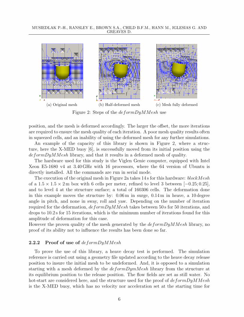
In Figure 4a the surface-elevation of 2D wave-only simulations of the steepest case areplotted in colour against the reference simulation, the dotted line. Figure 4b presentsthe correlation between a hot-started simulation and the reference one, as a function ofthe tminus used for each simulation. The wave cases are numbered by their experimentalmeasured steepness [6].
(a) The surface-elevation of three different hot-started2D wave-only simulations, for the steepest case com-pared with the reference
(b) Correlation comparison of the surface-elevation of2D simulations starting at a specific time against thereference one
Figure 4: The surface-elevation hot-start results
The surface-elevation of the hot-started simulation with tminus = 4 is the green line inFigure 4a, and is on top of the reference one. Indeed, in Figure 4b, tminus = 4 clearlyappears as the first converged solution for the surface-elevation representation. And,
8
MUSIEDLAK P.-H., RANSLEY E., BROWN S.A., CHILD B.F.M., HANN M., IGLESIAS G. ANDGREAVES D.
unexpectedly, this result is valid for the four cases, hence not depending on the steepnessor the non-linearity of the wave. But, the convergence of the solution is slower as thenon-linearity of the wave increases. Consequently, if a lower correlation criterion wouldbe used, a lower tminus could be used for the less steep cases.
As expected, when no build-up period is allowed, for tminus = 0, the sum of linearcomponent is set as the initial condition across the NWT, which results in significantdifferences, as shown by the blue curve in Figure 4a.
3.1.2 Velocity and Pressure
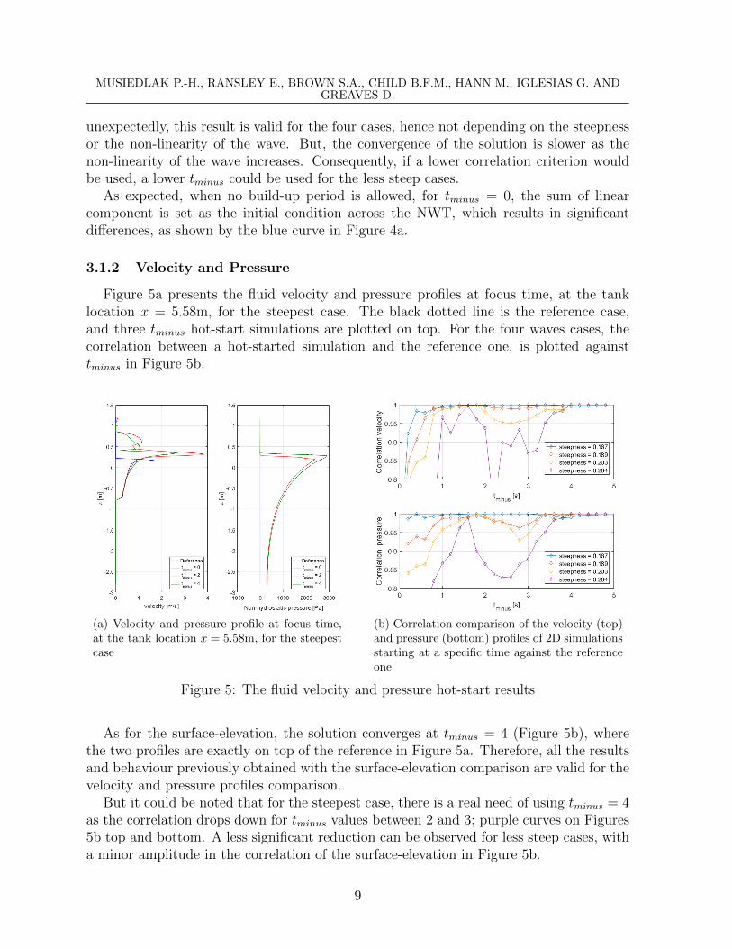
Figure 5a presents the fluid velocity and pressure profiles at focus time, at the tanklocation x = 5.58m, for the steepest case. The black dotted line is the reference case,and three tminus hot-start simulations are plotted on top. For the four waves cases, thecorrelation between a hot-started simulation and the reference one, is plotted againsttminus in Figure 5b.
(a) Velocity and pressure profile at focus time,at the tank location x = 5.58m, for the steepestcase
(b) Correlation comparison of the velocity (top)and pressure (bottom) profiles of 2D simulationsstarting at a specific time against the referenceone
Figure 5: The fluid velocity and pressure hot-start results
As for the surface-elevation, the solution converges at tminus = 4 (Figure 5b), wherethe two profiles are exactly on top of the reference in Figure 5a. Therefore, all the resultsand behaviour previously obtained with the surface-elevation comparison are valid for thevelocity and pressure profiles comparison.
But it could be noted that for the steepest case, there is a real need of using tminus = 4as the correlation drops down for tminus values between 2 and 3; purple curves on Figures5b top and bottom. A less significant reduction can be observed for less steep cases, witha minor amplitude in the correlation of the surface-elevation in Figure 5b.
9
MUSIEDLAK P.-H., RANSLEY E., BROWN S.A., CHILD B.F.M., HANN M., IGLESIAS G. ANDGREAVES D.
Using a tminus = 4 hot-start simulation compare to a conventional one allows a reduc-tion of 25% of CPU for the least steep case, and of 12% for the steepest one.
3.2 Positioning the structure and assigning initial motion state
3.2.1 Hot-start heave decay test
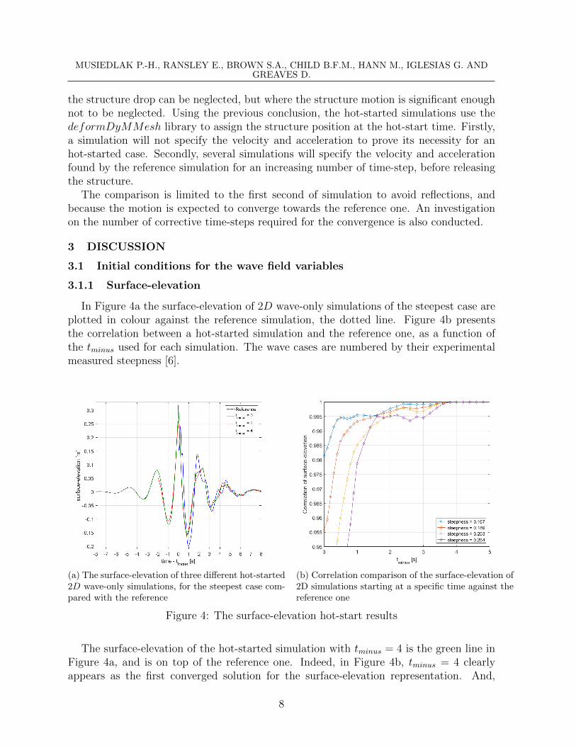
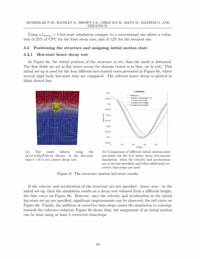
In Figure 6a, the initial position of the structure is set, thus the mesh is deformed.The flow fields are set as flat water across the domain (water is in blue, air in red). Thisinitial set-up is used for the four different hot-started cases presented in Figure 6b, whereseveral rigid body hot-start tries are compared. The referent heave decay is plotted inblack dotted line.
(a) The mesh deform using thedeformDyMMesh library, at the hot-starttime t = 0.1 s for a heave decay test
(b) Comparison of different initial motion-stateprocedure for the 0.1s heave decay hot-startedsimulation: when the velocity and accelerationare or are not specified; and when additional cor-rective time-steps are used
Figure 6: The structure motion hot-start results
If the velocity and acceleration of the structure are not specified - hence zero - in theinitial set-up, then the simulation results as a decay test released from a different height;the blue curve on Figure 6b. However, once the velocity and acceleration in the initialhot-start set-up are specified, significant improvements can be observed; the red curve onFigure 6b. Finally, the addition of corrective time-steps causes the simulation to convergetowards the reference solution; Figure 6b shows that, the assignment of an initial motioncan be done using at least 5 corrective time-steps.
10

MUSIEDLAK P.-H., RANSLEY E., BROWN S.A., CHILD B.F.M., HANN M., IGLESIAS G. ANDGREAVES D.
4 CONCLUSIONS
- This paper investigates the starting of a WSI CFD simulation from an advancetime, named hot-start. It aims to reduce the CFD simulation strictly around thenon-linear event, by reducing the build-up time usually used in CFD to launch asimulation. It also constitutes an important piece of a future coupling procedure.In this study, the hot-start investigations are restricted to the wave field and thestructure motion, separately.
- Compared to a non hot-started CFD simulation, the representation of the focusevent was found to be accurately reproduced if started 4s before the main event;hence not requiring more than 6s of simulation. This conclusion was found to beindependent on the non-linearity of the wave, and also confirmed through the threeflow field: surface-elevation, water column velocity and pressure.
- A new library - deformDyMMesh - was achieved in order to deform the meshaccording to the structure position at hot-start, and its use was proven to have noinfluence on the results of the simulation.
- The assignment of motion of a structure was found to require at least 5 correctivetime-steps - where each position and motion found by the previous time-step werecorrected using the reference case - before converging to the referent solution.
- Therefore, this study proves the use and possibility of an advance start for CFDsimulations in WSI cases based on a focus event. The method and the results areexpected to be adaptive to other WSI in different CFD applications.
5 ACKNOWLEDGEMENTS
The code presented here is available through the Collaborative Computational Projectin Wave Structure Interaction (CCP-WSI) [EP/M022382/1], which brings together theWSI community to share CFD developments in an open source environment (https://www.ccp-wsi.ac.uk) [14].
The author would like to thank his supervision team for their everyday help and advices.Thanks to S.A. Brown for its reliable help in OpenFOAM coding. Also, the author wouldlike to thank all people involved in OpenFOAM development, from small codes to onlinetutorial and forums.
REFERENCES
[1] CCP-WSI Working Group, Wave Structure Interaction Computation and ExperimentRoadmap - Part 1: A Report on the 1st CCP-WSI Focus Group Workshop, 2016
[2] Ransley, E (2015). ”Survivability of wave energy converter and mooring coupled sys-tem using CFD”, PhD thesis, School of Marine Science and Engineering, Universityof Plymouth
11
MUSIEDLAK P.-H., RANSLEY E., BROWN S.A., CHILD B.F.M., HANN M., IGLESIAS G. ANDGREAVES D.
[3] Pinna, R., Cassidy, M., Dynamic analysis of a monopod platform using constrainedNewWave, International Conference on Offshore Mechanics and Arctic Engineering,23rd International Conference on Offshore Mechanics and Arctic Engineering, Vol-ume 2. (pp. 141-148). doi:10.1115/OMAE2004-51158.
[4] Rafiee, A.; Wolgamot, H.; Draper, S.; Orszaghova, J.; Fivez, J.; Sawyer, T. Iden-tifying the design wave group for the extreme response of a point absorber waveenergy converter. In Proceedings of the Asian Wave and Tidal Energy Conference(AWTEC), Singapore, 2428 October 2016
[5] Musiedlak, P-H, Ransley, E, Greaves, D, Child, B, Hann,Mand Iglesias, G (2017).Investigations of model validity for numerical survivability testing of WECs , Pro-ceedings of the 12th European Wave and Tidal Energy Conference (EWTEC), Cork,Ireland.
[6] Hann, M., Greaves, D. & Raby, A. (2015), ’Snatch loading of a single taut mooredfloating wave energy converter due to focussed wave groups’, Ocean Engineering 96,258271. URL: http://dx.doi.org/10.1016/j.oceaneng.2014.11.011
[7] Halcrow (2006), South West of England Regional Development Agency, Wave Hubdevelopment and design phase, coastal processes study report, pp19, 2006.
[8] Chaplin, J. R. (1996), On frequency-focusing unidirectional waves, InternationalJournal of Offshore and Polar Engineering, 6(2), 131137.
[9] Xu,L., Barltrop,N., Okan, B.,(2008). Bow impact loading on FP-SOs 1 - experimental investigation, Ocean Engineering 35, 11481157,https://doi.org/10.1016/j.oceaneng.2008.04.013
[10] Musiedlak PH., Greaves D., Child B., Iglesias G., Hann M., and Ransley E.J., Ge-ometric parameters for a 2D-Numerical Wave Tank, International Network for Off-shore Renewable Energy, 12-18 June 2016, Nantes, France; and PRIMaRe 2016,University of Bath UK.
[11] Jacobsen, N, Fuhrman, D and Fredse, J (2012). A wave generation toolbox for theopen-source CFD library: OpenFOAM R©, International Journal for Numerical Meth-ods in Fluids, Vol. 70, pp. 10731088
[12] Brown S.A., Musiedlak P.H., Ransley E.J. and Greaves D.,” Numerical simulation offocused wave interactions with a fixed FPSO using OpenFOAM 4.1”, ISOPE (2018)
[13] Greaves, D., Borthwick, A., 1999. Hierarchical tree-based finite element mesh gener-ation. Int. J. Numer. Meth. Eng. 45, 447471.
[14] A Collaborative Computational Project in Wave Structure Interactionhttp://www.ccp-wsi.ac.uk/
12