start tekla structures...1start tekla structures when you start tekla structures, you are asked to...
TRANSCRIPT

Tekla Structures 2017iBasics of Tekla Structures
September 2017
©2017 Trimble Solutions Corporation
Contents
1 Start Tekla Structures................................................................... 91.1 What is a blank project...................................................................................111.2 Check or change your Tekla Structures setup............................................. 12
2 Open, create, and save 3D models............................................ 142.1 Open a model...................................................................................................152.2 Create a new model ....................................................................................... 162.3 Create a thumbnail image of a model.......................................................... 172.4 Edit project properties....................................................................................172.5 Create model templates.................................................................................20
Create a new model template..............................................................................................20Modify an existing model template.....................................................................................21Download model templates................................................................................................. 21 Model template options.......................................................................................................21
2.6 Save a model ................................................................................................... 22Save the current model.........................................................................................................22Save a copy with different name or location......................................................................22Save a backup copy............................................................................................................... 23Save as a model template.....................................................................................................23Define autosave settings...................................................................................................... 23
3 Get familiar with the user interface......................................... 253.1 How to use commands................................................................................... 263.2 Zoom and rotate the model........................................................................... 28
Zoom in and out.................................................................................................................... 28Rotate the model................................................................................................................... 28Pan the model........................................................................................................................29
3.3 Find commands and dialog boxes................................................................. 303.4 Learn the common buttons........................................................................... 313.5 Change the appearance of the ribbon..........................................................323.6 View status bar messages.............................................................................. 323.7 Minimize the ribbon........................................................................................333.8 How to use the contextual toolbar............................................................... 34
How to change object properties using contextual toolbar............................................. 34Show or hide contextual toolbar......................................................................................... 34Define contextual toolbar's position................................................................................... 34Pin contextual toolbar in place............................................................................................ 35Minimize contextual toolbar................................................................................................ 35................................................................................................................................................. 36
3.9 How to use the side pane............................................................................... 36
2
3.10 Change the language...................................................................................... 373.11 Basic settings in the File menu......................................................................38
4 Set up the workspace..................................................................434.1 Change units and decimals............................................................................ 434.2 Create grids and grid lines............................................................................. 44
Create a grid........................................................................................................................... 45Modify a grid.......................................................................................................................... 46Delete a grid........................................................................................................................... 47Add a single grid line............................................................................................................. 47
Add a grid line between existing grid lines................................................................... 47Add a grid line between two points............................................................................... 48
Modify a single grid line........................................................................................................ 48Modify grid line properties..............................................................................................48Move a grid line................................................................................................................ 48Stretch, shrink, or incline a grid line...............................................................................49Change a grid line label................................................................................................... 49Turn grid line stretching off.............................................................................................49
Deleting a single grid line......................................................................................................50Delete a grid line using direct modification.................................................................. 50Delete a grid line (alternative method)..........................................................................50
4.3 Create model views.........................................................................................50Move the view plane..............................................................................................................52Create views........................................................................................................................... 52
Create a basic view of the model....................................................................................52Create a view using two points....................................................................................... 52Create a view using three points.................................................................................... 53Create a view of the work plane..................................................................................... 53Create grid views.............................................................................................................. 53Create a view on a plane................................................................................................. 56Create a 3D view of a part............................................................................................... 57Create default part views................................................................................................ 57Create an undeformed part view................................................................................... 57Create a 3D view of a component.................................................................................. 57Create default component views....................................................................................58Create a surface view.......................................................................................................58Create a surface view along selected edge................................................................... 60
Open a view............................................................................................................................ 61Save a view............................................................................................................................. 62Modify a view......................................................................................................................... 62Delete a view.......................................................................................................................... 63Switch between views........................................................................................................... 63
Switch between open views............................................................................................ 63Switch between 3D and plane view................................................................................63
Update and refresh views.....................................................................................................644.4 Define the work area...................................................................................... 64
Fit work area to entire model...............................................................................................65Fit work area to selected parts.............................................................................................65Fit work area using two points............................................................................................. 65Hide the work area box.........................................................................................................66
4.5 Coordinate system.......................................................................................... 66Show or hide the work plane grid........................................................................................67
3
Shift the work plane.............................................................................................................. 68Set work plane to any part plane................................................................................... 68Set work plane parallel to xyz plane.............................................................................. 68Set work plane using one point...................................................................................... 69Set work plane using two points.................................................................................... 69Set work plane using three points..................................................................................69Set work plane parallel to view plane............................................................................ 70Restore the default work plane...................................................................................... 70
4.6 Change the color settings...............................................................................70Find RGB values for colors....................................................................................................70Change the background color..............................................................................................72Change the color of dimensions, part labels, and grids................................................... 75
5 Create, modify, and delete objects............................................775.1 Create an object.............................................................................................. 775.2 Modify object properties in a dialog box......................................................775.3 Modify object properties in the property pane........................................... 785.4 Delete an object.............................................................................................. 805.5 Resize and reshape an object........................................................................ 815.6 Copy properties from another object........................................................... 87
Copy properties using property pane................................................................................. 87Copy properties using contextual toolbar.......................................................................... 88
5.7 Save and load object properties....................................................................88Save and load properties in a dialog box............................................................................88Save and load properties in the property pane................................................................. 89Remove existing properties..................................................................................................90
6 Snap to a point or line.................................................................916.1 Snap to a line................................................................................................... 916.2 Snap to extension lines.................................................................................. 926.3 Snap to orthogonal points............................................................................. 946.4 Snap relative to previously picked points.................................................... 956.5 Create a temporary reference point.............................................................966.6 Lock X, Y, or Z coordinate............................................................................... 986.7 Snapping toolbar............................................................................................. 98
Snap zone............................................................................................................................... 99Snap depth............................................................................................................................. 99Snap priority...........................................................................................................................99Snapping in drawings............................................................................................................99
6.8 Snap switches and symbols........................................................................... 996.9 Snap to a point using exact distance or coordinates................................101
Enter a distance or coordinates.........................................................................................101Options for coordinates......................................................................................................102Change the snapping mode............................................................................................... 103
6.10 Align objects using a snap grid.................................................................... 1036.11 Override the current snap switch............................................................... 1046.12 Example: Track along a line towards a snap point.................................... 104
4
6.13 Snap settings................................................................................................. 107
7 Select objects............................................................................. 1097.1 Select single objects......................................................................................1097.2 Select multiple objects................................................................................. 1107.3 Select all objects............................................................................................1107.4 Select handles................................................................................................1117.5 Modify the selection..................................................................................... 1127.6 Selection switches ........................................................................................1127.7 Select assemblies and cast units.................................................................1167.8 Select nested objects.................................................................................... 1167.9 Select reference models, reference model objects and assemblies....... 117
Select an entire reference model...................................................................................... 117Select a reference model object........................................................................................ 117Select a reference model assembly...................................................................................118
7.10 If you cannot select objects......................................................................... 118
8 Copy and move objects............................................................. 1198.1 Copy objects...................................................................................................120
Copy by picking two points.................................................................................................120Copy linearly.........................................................................................................................122Copy by specifying a distance from origin........................................................................122Copy using drag-and-drop..................................................................................................123Copy objects to another object..........................................................................................124Copy all content to another object....................................................................................124Copy to another plane........................................................................................................ 125Copy from another model.................................................................................................. 125Copy objects using linear array tool..................................................................................126
How to use Linear array tool.........................................................................................126How to define the settings............................................................................................ 127
Copy objects using radial array tool..................................................................................128How to use Radial array tool.........................................................................................129How to define the settings............................................................................................ 130
Copy objects using Array of objects (29) component ....................................................1318.2 Move objects.................................................................................................. 132
Move by picking two points................................................................................................132Move linearly........................................................................................................................134Move by specifying a distance from origin....................................................................... 135Move using drag-and-drop................................................................................................. 135Move to another plane....................................................................................................... 137Move objects to another object......................................................................................... 137
8.3 Rotate objects................................................................................................138Rotate around a line............................................................................................................138Rotate around the z axis.....................................................................................................139Rotate drawing objects....................................................................................................... 141
8.4 Mirror objects................................................................................................ 142Mirror model objects.......................................................................................................... 142Mirror drawing objects........................................................................................................142
5
9 Filter objects...............................................................................1449.1 Use existing filters........................................................................................ 145
How to use a view filter.......................................................................................................145How to use a selection filter...............................................................................................146
9.2 Create new filters..........................................................................................147Create a view filter...............................................................................................................147Create a selection filter....................................................................................................... 149Create a drawing filter.........................................................................................................150Create a drawing view filter................................................................................................150Create a drawing selection filter........................................................................................ 151
9.3 Filtering techniques...................................................................................... 1519.4 Object properties in filtering....................................................................... 1549.5 Template attributes in filtering...................................................................1689.6 Wildcards .......................................................................................................1689.7 Examples of filters........................................................................................ 169
Filter parts based on their name....................................................................................... 169Filter main parts...................................................................................................................170Filter bolts based on their size...........................................................................................171Filter parts based on their assembly type........................................................................ 171Filter sub-assemblies.......................................................................................................... 173Filter reference model objects........................................................................................... 173Filter parts within component............................................................................................174
9.8 Copy and remove filters............................................................................... 175Copy a filter to another model...........................................................................................175Remove a filter..................................................................................................................... 176
10 Take screenshots....................................................................... 17710.1 Take a screenshot of a model...................................................................... 17710.2 Take a screenshot of a drawing................................................................... 17810.3 Save a screenshot in bitmap format...........................................................178
11 Default keyboard shortcuts..................................................... 17911.1 Common commands..................................................................................... 17911.2 Rendering options.........................................................................................18011.3 Selecting objects............................................................................................18011.4 Snapping.........................................................................................................18011.5 Copying and moving objects........................................................................ 18111.6 Viewing the model.........................................................................................18111.7 Checking the model...................................................................................... 18211.8 Drawings.........................................................................................................182
12 Tips for basic tasks.................................................................... 18412.1 Switch rollover highlight on or off ............................................................. 18512.2 Select values from the model...................................................................... 18612.3 Interrupt object selection............................................................................ 186
6
12.4 Select on right-click.......................................................................................18712.5 Copy and move efficiently............................................................................18712.6 Change a property in several parts at the same time.............................. 18712.7 How to restore missing toolbars................................................................. 18812.8 Show or hide "Do not show this message again"...................................... 188
13 Disclaimer...................................................................................190
7

8
1 Start Tekla Structures
When you start Tekla Structures, you are asked to choose your Tekla Structuressetup. The setup consists of an environment, role, and configuration.
• Environment means region-specific settings and information. It defineswhich profiles, material grades, default values, connections, wizards,variables, reports, and templates you have available.
• Role is a user group profile that limits the availability of files and settings inan environment. The user interface has been customized for each role.
• Configuration consists of a set of features that the user is entitled to basedon the license agreement. Each configuration is meant for a specific usergroup, to suit the various players in the construction industry.
1. Start Tekla Structures by selecting it from the Windows Start menu or bydouble-clicking the desktop icon.
Start Tekla Structures 9
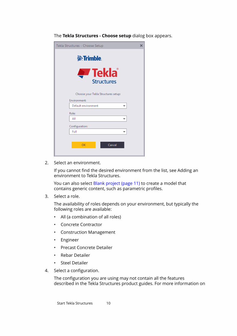
The Tekla Structures - Choose setup dialog box appears.
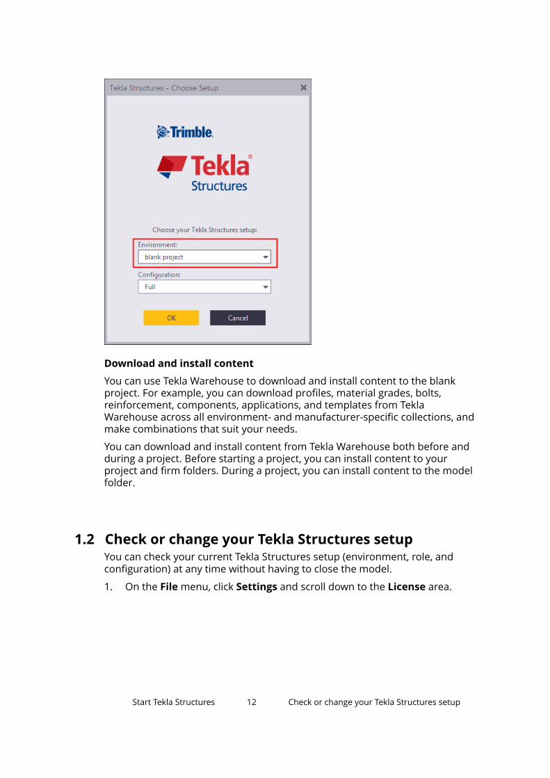
2. Select an environment.
If you cannot find the desired environment from the list, see Adding anenvironment to Tekla Structures.
You can also select Blank project (page 11) to create a model thatcontains generic content, such as parametric profiles.
3. Select a role.
The availability of roles depends on your environment, but typically thefollowing roles are available:
• All (a combination of all roles)
• Concrete Contractor
• Construction Management
• Engineer
• Precast Concrete Detailer
• Rebar Detailer
• Steel Detailer
4. Select a configuration.
The configuration you are using may not contain all the featuresdescribed in the Tekla Structures product guides. For more information on
Start Tekla Structures 10
the features available in each configuration, see Tekla Structuresconfigurations.
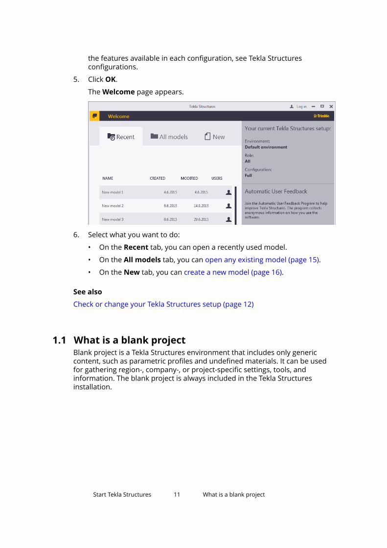
5. Click OK.
The Welcome page appears.
6. Select what you want to do:
• On the Recent tab, you can open a recently used model.
• On the All models tab, you can open any existing model (page 15).
• On the New tab, you can create a new model (page 16).
See also
Check or change your Tekla Structures setup (page 12)
1.1 What is a blank projectBlank project is a Tekla Structures environment that includes only genericcontent, such as parametric profiles and undefined materials. It can be usedfor gathering region-, company-, or project-specific settings, tools, andinformation. The blank project is always included in the Tekla Structuresinstallation.
Start Tekla Structures 11 What is a blank project
Download and install content
You can use Tekla Warehouse to download and install content to the blankproject. For example, you can download profiles, material grades, bolts,reinforcement, components, applications, and templates from TeklaWarehouse across all environment- and manufacturer-specific collections, andmake combinations that suit your needs.
You can download and install content from Tekla Warehouse both before andduring a project. Before starting a project, you can install content to yourproject and firm folders. During a project, you can install content to the modelfolder.
1.2 Check or change your Tekla Structures setupYou can check your current Tekla Structures setup (environment, role, andconfiguration) at any time without having to close the model.
1. On the File menu, click Settings and scroll down to the License area.
Start Tekla Structures 12 Check or change your Tekla Structures setup
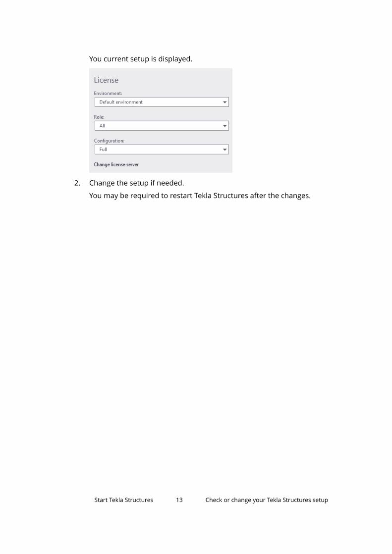
You current setup is displayed.
2. Change the setup if needed.
You may be required to restart Tekla Structures after the changes.
Start Tekla Structures 13 Check or change your Tekla Structures setup

2 Open, create, and save 3Dmodels
With Tekla Structures, you can create a 3D real-life model of any structure. Themodel contains all the information that is needed to manufacture andconstruct the structure: part geometry and dimensions, profiles, materials,connection types, and so on.
• Open a model (page 15)
• Create a new model (page 16)
• Create model templates (page 20)
• Save a model (page 22)
Model output
The 3D model is also the single source of information for drawings and otheroutputs, such as reports and NC data files. This ensures that the information indrawings and reports is always up to date, as they react to modifications in themodel.
Collaboration
You can use the multi-user mode or Tekla Model Sharing to workcollaboratively within a model.
Open, create, and save 3D models 14 Check or change your Tekla Structures setup
2.1 Open a modelYou can have one model open at a time. If you open a model and already haveone open, Tekla Structures prompts you to save the first model.
1. On the File menu, click Open.
2. Select the model you want to open.
• To search for models in another folder, click Browse.
• To open a recently used model folder, click the Open model fromfolder list.
• To sort models by name, date, or type, click the column titles.
• When the models are sorted alphabetically by their names, you canuse the keyboard to select a model. For example, when you type N,Tekla Structures selects the first model starting with an N.
Open, create, and save 3D models 15 Open a model
3. Click Open.
If no views (page 50) are visible in the model, Tekla Structures promptsyou to select one.
See also
Create a new model (page 16)
Create a thumbnail image of a model (page 16)
2.2 Create a new modelCreate a separate model for each Tekla Structures project. Each model isstored in its own folder under the TeklaStructuresModels folder.
1. On the File menu, click New.
2. In the name box, enter a name for the new model.
Do not use special characters (/ \ ; : | ). We recommend that you tryto decide on a permanent name at this point. The name of the model canbe changed afterwards, but it involves changing several file names.
3. Define where to save the new model.
By default, the model is saved in the TeklaStructuresModels folderthat was created during installation. You can change the default folder byclicking Browse. You can also select a recently used folder from the Savein list.
4. If you want to use a model template (page 20), select one.
5. Under Type, define whether to run Tekla Structures in single-user ormulti-user mode.
• Single-user: the model will be used by one person at a time.
• Multi-user: the model is stored on a server and may be used by severalpeople simultaneously. Enter the name of the server in the Server box.
6. Click Create.
Tekla Structures creates the model and opens the default model view(page 61). The contents of the model view may differ based on themodel template you chose in step 4.
See also
Create a thumbnail image of a model (page 16)
Edit project properties (page 17)
Open, create, and save 3D models 16 Create a new model
2.3 Create a thumbnail image of a modelYou can add a thumbnail image to make it easier to recognize your projecteven when you do not remember the exact name of the model. The thumbnailimage is displayed when you browse for existing models.
1. On the View tab, click Screenshot --> Project thumbnail.
2. Select a view.
Tekla Structures creates the image and saves it in the model folder withthe name thumbnail.png.
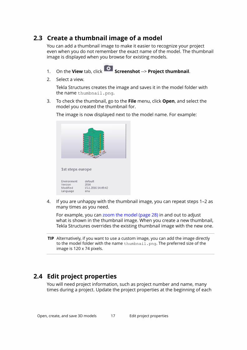
3. To check the thumbnail, go to the File menu, click Open, and select themodel you created the thumbnail for.
The image is now displayed next to the model name. For example:
4. If you are unhappy with the thumbnail image, you can repeat steps 1–2 asmany times as you need.
For example, you can zoom the model (page 28) in and out to adjustwhat is shown in the thumbnail image. When you create a new thumbnail,Tekla Structures overrides the existing thumbnail image with the new one.
TIP Alternatively, if you want to use a custom image, you can add the image directlyto the model folder with the name thumbnail.png. The preferred size of theimage is 120 x 74 pixels.
2.4 Edit project propertiesYou will need project information, such as project number and name, manytimes during a project. Update the project properties at the beginning of each
Open, create, and save 3D models 17 Edit project properties
project to make reports and drawings display the correct informationautomatically. All of the fields are optional.
1. On the File menu, click Project properties.
2. Click Edit.
3. In the Description box, enter a description that helps you identify themodel when you next need to open it.
4. If you want to use another coordinate system for interoperability andcollaboration, click Base points to define a new base point.
Once a base point has been defined, you can select it from the Locationby list.
5. Edit the other project properties.
6. To define project-specific user-defined attributes, click User-definedattributes.
By default, you can define:
• Project comment
• User fields
• Execution class
• IFC export attributes
• GEO coordinates
• Status attributes
• Unitechnic factory location
The availability of user-defined attributes depends on your environment(page 9).
7. Click Apply to save your changes.
Now you will get updated project properties in drawings and reports.
Displaying project information in templates and reports
The fields in the image below refer to template attributes, which you can usewhen designing your own reports and templates. To display projectinformation, add the corresponding template attributes in the templates andreports.
Open, create, and save 3D models 18 Edit project properties
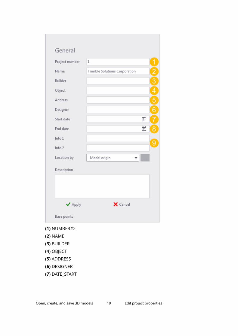
(1) NUMBER#2
(2) NAME
(3) BUILDER
(4) OBJECT
(5) ADDRESS
(6) DESIGNER
(7) DATE_START
Open, create, and save 3D models 19 Edit project properties
(8) DATE_END
(9) INFO1, INFO2
2.5 Create model templatesModel templates allow you to start a model with predefined companytemplates and settings. This can be especially useful for sub-contractors.
Only single-user models can be created with model templates. If you wish tocreate a multi-user model using a model template, create the model in single-user mode and then switch to multi-user mode.
By default, the model template folder is saved in your environment folder. Usethe advanced option XS_MODEL_TEMPLATE_DIRECTORY to define a differentlocation.
Create a new model templateYou can create your own model templates and use them for creating newmodels. You can select which catalogs, custom components, model subfolders,drawing templates, and report templates from the model are included in themodel template.
1. Create a new model (page 16).
Always start by creating a new empty model. This is because old modelsthat have been used in live projects cannot be completely cleaned. Theymay contain excess information that increases the size of the model evenif you delete all objects and drawings from the model.
2. Add the desired part properties, drawing properties, profiles, materials,custom components, sketches, and so on, in the model.
You can copy the needed attribute files from another model, for example.
3. On the File menu, click Save --> Save as model template.
4. Enter a name for the model template.
5. Select which catalogs, drawing templates, report templates, and modelsubfolders to include in the model template.
For more information, see Model template options.
You can only select files and folders that are available in the model folder.Catalogs are typically located in the Environment folder and they areincluded in the model folder only if they have been modified.
6. If you want to open the destination folder after creating the modeltemplate, select the check box.
Open, create, and save 3D models 20 Create model templates
7. Click OK.
You can now use the model template for creating new models.
Modify an existing model templateTo modify an existing template, save the model as a new template.Alternatively, you can modify the template by copying new or updated filesdirectly to the model template folder.
1. Create a model using the existing model template.
2. Make the needed changes.
3. Save it as a new model template.
Download model templatesYou can download, share, and store model templates using Tekla Warehouse.
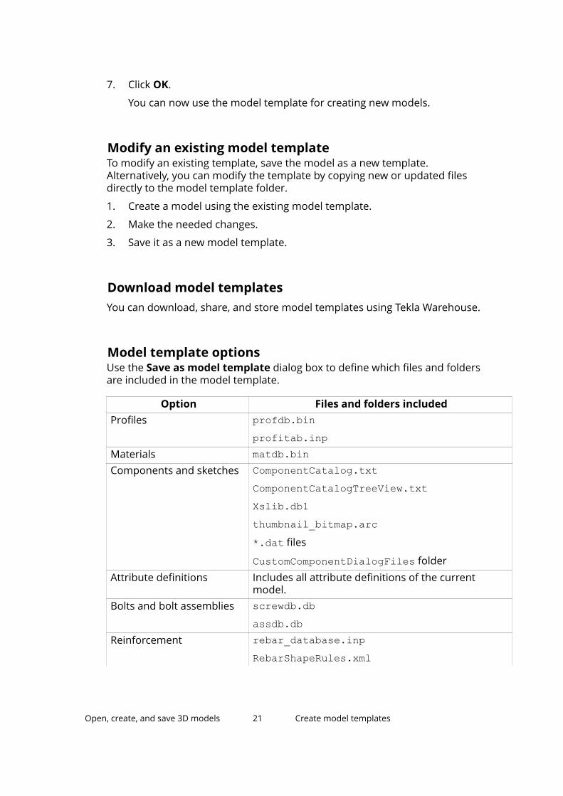
Model template optionsUse the Save as model template dialog box to define which files and foldersare included in the model template.
Option Files and folders includedProfiles profdb.bin
profitab.inpMaterials matdb.binComponents and sketches ComponentCatalog.txt
ComponentCatalogTreeView.txtXslib.db1thumbnail_bitmap.arc*.dat files
CustomComponentDialogFiles folderAttribute definitions Includes all attribute definitions of the current
model.Bolts and bolt assemblies screwdb.db
assdb.dbReinforcement rebar_database.inp
RebarShapeRules.xml
Open, create, and save 3D models 21 Create model templates
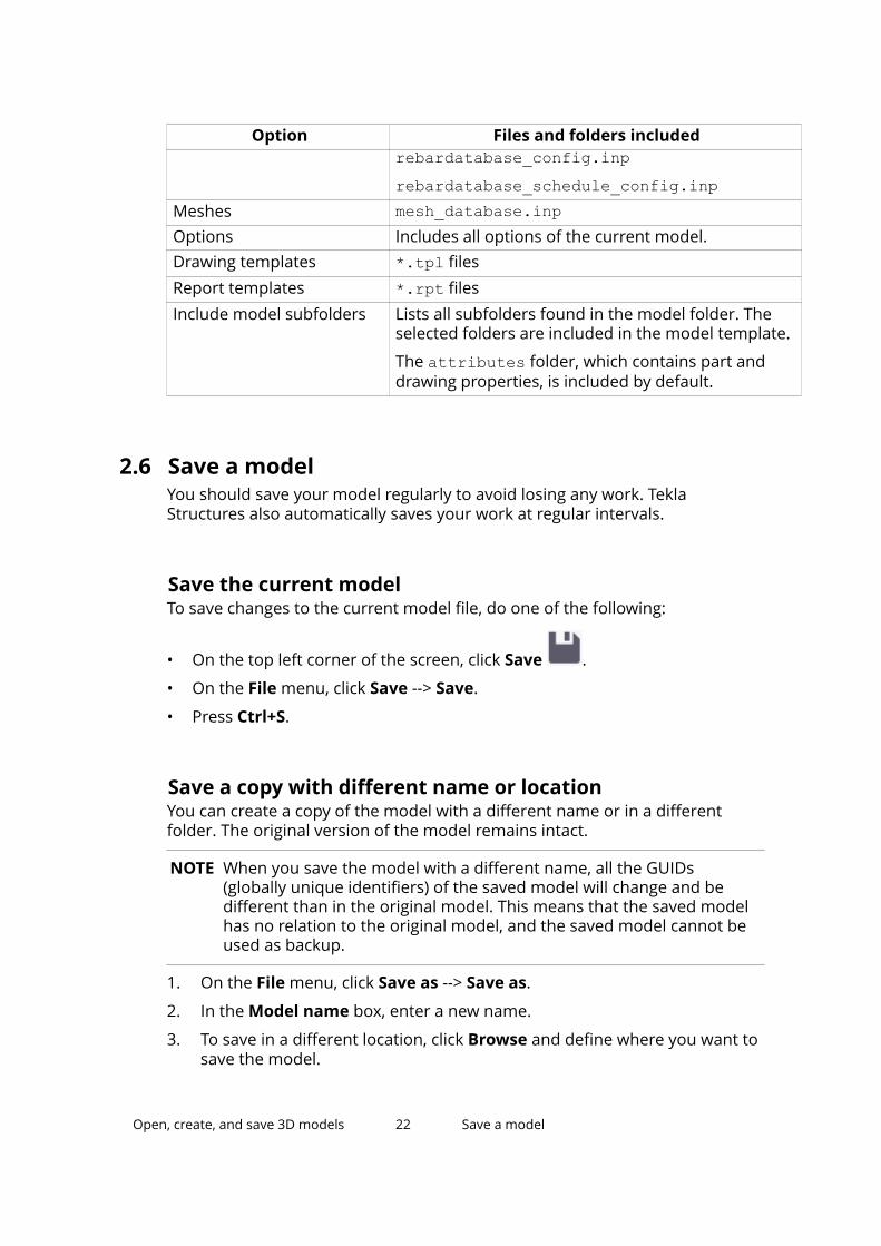
Option Files and folders includedrebardatabase_config.inprebardatabase_schedule_config.inp
Meshes mesh_database.inpOptions Includes all options of the current model.Drawing templates *.tpl filesReport templates *.rpt filesInclude model subfolders Lists all subfolders found in the model folder. The
selected folders are included in the model template.
The attributes folder, which contains part anddrawing properties, is included by default.
2.6 Save a modelYou should save your model regularly to avoid losing any work. TeklaStructures also automatically saves your work at regular intervals.
Save the current modelTo save changes to the current model file, do one of the following:
• On the top left corner of the screen, click Save .
• On the File menu, click Save --> Save.
• Press Ctrl+S.
Save a copy with different name or locationYou can create a copy of the model with a different name or in a differentfolder. The original version of the model remains intact.
NOTE When you save the model with a different name, all the GUIDs(globally unique identifiers) of the saved model will change and bedifferent than in the original model. This means that the saved modelhas no relation to the original model, and the saved model cannot beused as backup.
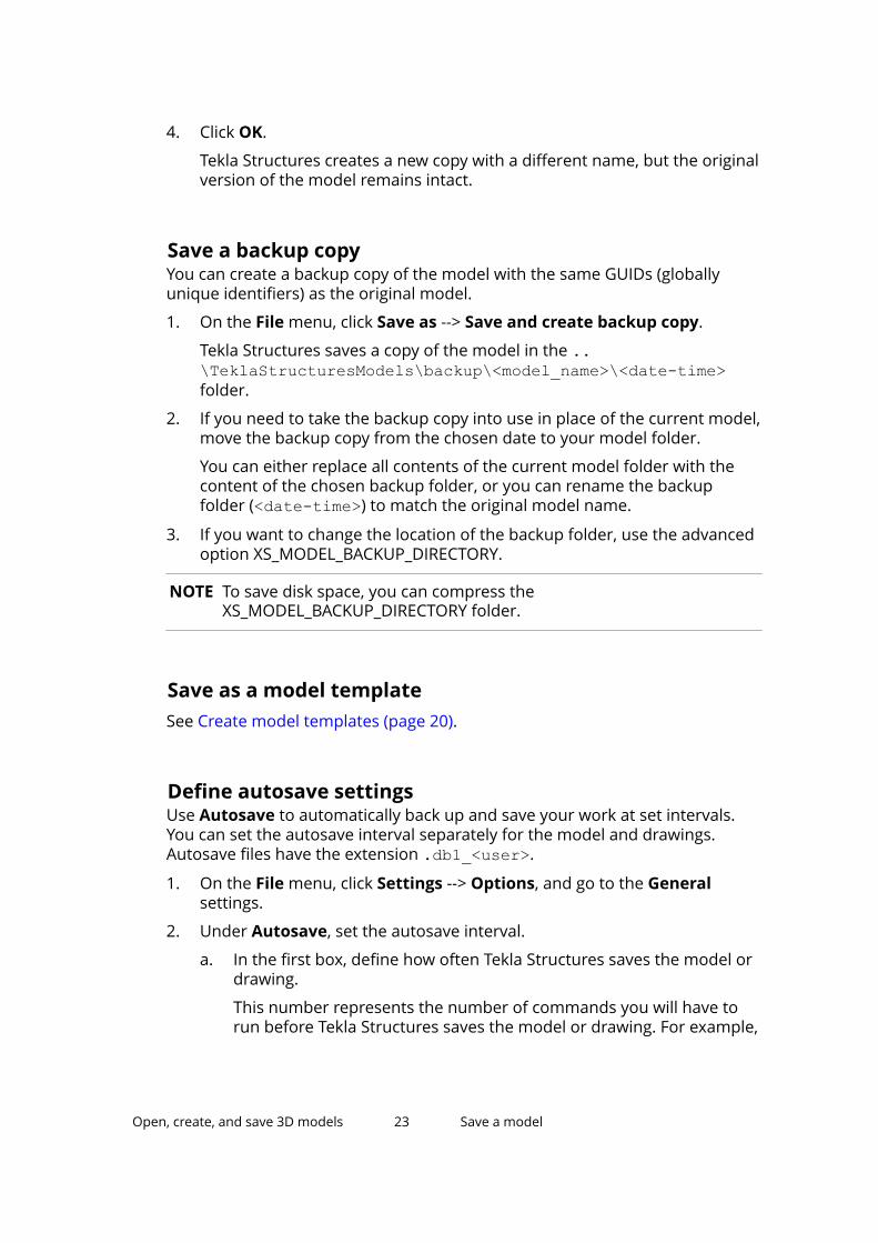
1. On the File menu, click Save as --> Save as.
2. In the Model name box, enter a new name.
3. To save in a different location, click Browse and define where you want tosave the model.
Open, create, and save 3D models 22 Save a model
4. Click OK.
Tekla Structures creates a new copy with a different name, but the originalversion of the model remains intact.
Save a backup copyYou can create a backup copy of the model with the same GUIDs (globallyunique identifiers) as the original model.
1. On the File menu, click Save as --> Save and create backup copy.
Tekla Structures saves a copy of the model in the ..\TeklaStructuresModels\backup\<model_name>\<date-time>folder.
2. If you need to take the backup copy into use in place of the current model,move the backup copy from the chosen date to your model folder.
You can either replace all contents of the current model folder with thecontent of the chosen backup folder, or you can rename the backupfolder (<date-time>) to match the original model name.
3. If you want to change the location of the backup folder, use the advancedoption XS_MODEL_BACKUP_DIRECTORY.
NOTE To save disk space, you can compress theXS_MODEL_BACKUP_DIRECTORY folder.
Save as a model templateSee Create model templates (page 20).
Define autosave settingsUse Autosave to automatically back up and save your work at set intervals.You can set the autosave interval separately for the model and drawings.Autosave files have the extension .db1_<user>.
1. On the File menu, click Settings --> Options, and go to the Generalsettings.
2. Under Autosave, set the autosave interval.
a. In the first box, define how often Tekla Structures saves the model ordrawing.
This number represents the number of commands you will have torun before Tekla Structures saves the model or drawing. For example,
Open, create, and save 3D models 23 Save a model
if you create many steel beams without interrupting the Create steelbeam command, it only counts as one command.
b. In the second box, enter the number of drawings after which TeklaStructures saves your work.
NOTE If you set the interval values to less than 2, autosave is disabled.
3. Click OK.
4. Define where to store the Autosave files.
By default, Tekla Structures stores the autosave files in the ..\TeklaStructuresModels\autosave folder. To change the folder, usethe advanced option XS_AUTOSAVE_DIRECTORY.
5. Define whether to keep old autosave files.
By default, Tekla Structures deletes the autosave files when you close amodel, to save disk space. To keep autosave files even if you exit TeklaStructures without saving the model, use the advanced optionXS_KEEP_AUTOSAVE_FILES_ON_EXIT_WHEN_NOT_SAVING.
Open, create, and save 3D models 24 Save a model
3 Get familiar with the userinterface
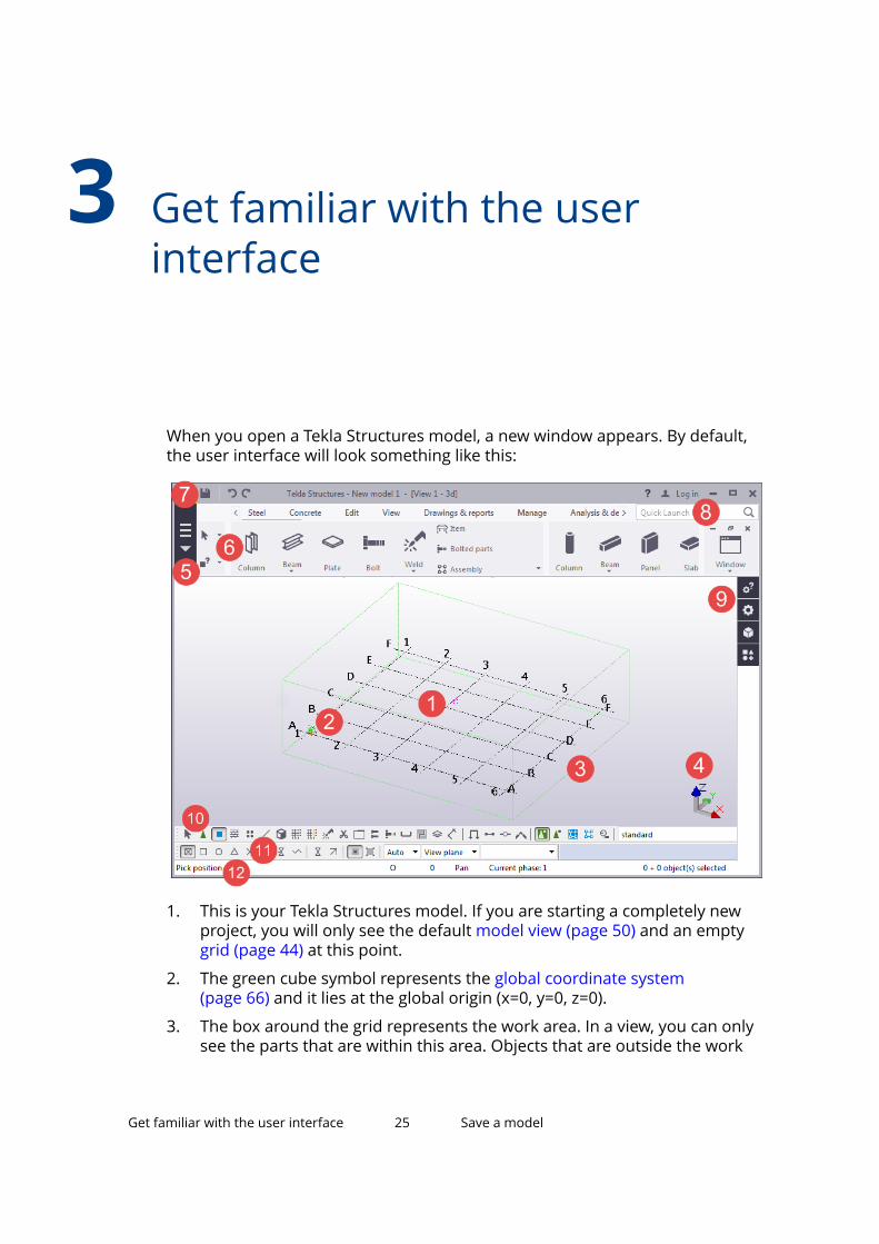
When you open a Tekla Structures model, a new window appears. By default,the user interface will look something like this:
1. This is your Tekla Structures model. If you are starting a completely newproject, you will only see the default model view (page 50) and an emptygrid (page 44) at this point.
2. The green cube symbol represents the global coordinate system(page 66) and it lies at the global origin (x=0, y=0, z=0).
3. The box around the grid represents the work area. In a view, you can onlysee the parts that are within this area. Objects that are outside the work
Get familiar with the user interface 25 Save a model
area exist in the model, but they are not visible. You can shrink andexpand the work area (page 64) to suit your needs. You can also hide thework area box (page 64).
4. The coordinate symbol with the three axes x, y, and z represents the localcoordinate system (page 66). It also indicates the direction of the model.
5. The File menu is where you manage your models. You can save models(page 22), print drawings, and import and export models, among otherthings.
6. The ribbon contains all the commands (page 26) and other functionsyou will use when building your model. You can customize the ribbonaccording to your needs.
7. By default, the Quick Access Toolbar contains the Save, Undo, and Redobuttons.
8. If you cannot find the command or dialog box you are looking for, searchwith Quick Launch (page 30).
9. Use the side pane (page 36) on the right-hand side of the screen to addreference models and components, or to view model object properties.
10. The selection switches (page 112) control which objects you can select.
11. The snap switches (page 99) control which positions you can pick whencreating objects.
12. When you create objects (page 26), the status bar (page 32) will tellyou how to proceed and when to pick points.
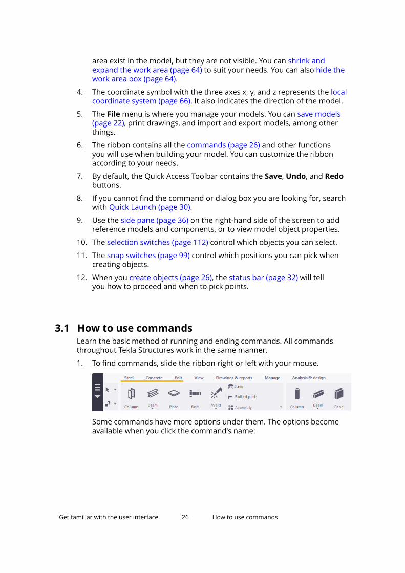
3.1 How to use commandsLearn the basic method of running and ending commands. All commandsthroughout Tekla Structures work in the same manner.
1. To find commands, slide the ribbon right or left with your mouse.
Some commands have more options under them. The options becomeavailable when you click the command's name:
Get familiar with the user interface 26 How to use commands
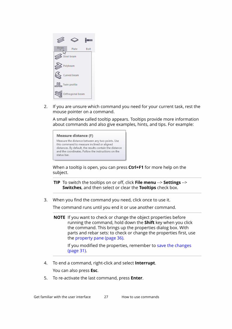
2. If you are unsure which command you need for your current task, rest themouse pointer on a command.
A small window called tooltip appears. Tooltips provide more informationabout commands and also give examples, hints, and tips. For example:
When a tooltip is open, you can press Ctrl+F1 for more help on thesubject.
TIP To switch the tooltips on or off, click File menu --> Settings -->Switches, and then select or clear the Tooltips check box.
3. When you find the command you need, click once to use it.
The command runs until you end it or use another command.
NOTE If you want to check or change the object properties beforerunning the command, hold down the Shift key when you clickthe command. This brings up the properties dialog box. Withparts and rebar sets: to check or change the properties first, usethe property pane (page 36).
If you modified the properties, remember to save the changes(page 31).
4. To end a command, right-click and select Interrupt.
You can also press Esc.
5. To re-activate the last command, press Enter.
Get familiar with the user interface 27 How to use commands
See also
Create, modify, and delete objects (page 77)
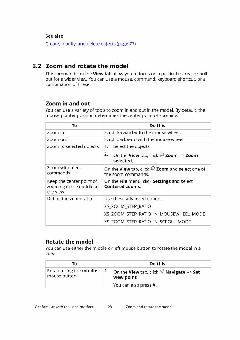
3.2 Zoom and rotate the modelThe commands on the View tab allow you to focus on a particular area, or pullout for a wider view. You can use a mouse, command, keyboard shortcut, or acombination of these.
Zoom in and outYou can use a variety of tools to zoom in and out in the model. By default, themouse pointer position determines the center point of zooming.
To Do thisZoom in Scroll forward with the mouse wheel.Zoom out Scroll backward with the mouse wheel.Zoom to selected objects 1. Select the objects.
2. On the View tab, click Zoom --> Zoomselected.
Zoom with menucommands
On the View tab, click Zoom and select one ofthe zoom commands.
Keep the center point ofzooming in the middle ofthe view
On the File menu, click Settings and selectCentered zooms.
Define the zoom ratio Use these advanced options:
XS_ZOOM_STEP_RATIO
XS_ZOOM_STEP_RATIO_IN_MOUSEWHEEL_MODE
XS_ZOOM_STEP_RATIO_IN_SCROLL_MODE
Rotate the modelYou can use either the middle or left mouse button to rotate the model in aview.
To Do thisRotate using the middlemouse button
1. On the View tab, click Navigate --> Setview point.
You can also press V.
Get familiar with the user interface 28 Zoom and rotate the model
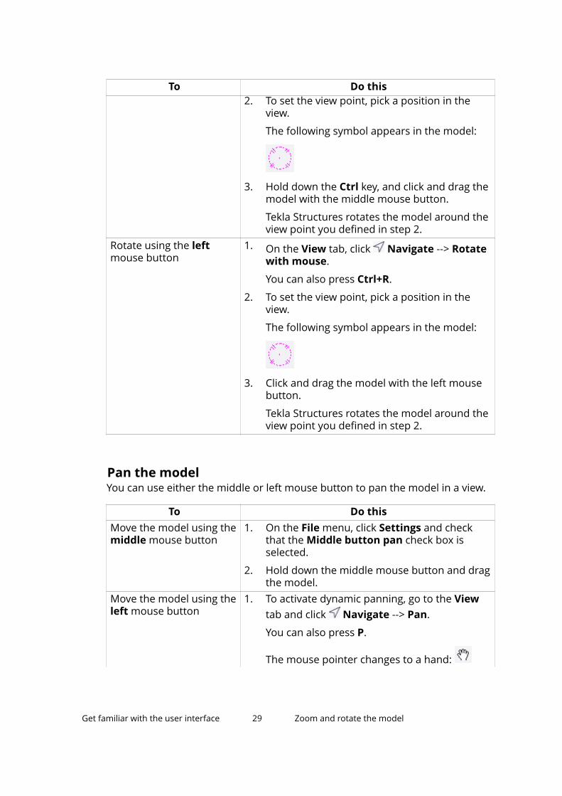
To Do this2. To set the view point, pick a position in the
view.
The following symbol appears in the model:
3. Hold down the Ctrl key, and click and drag themodel with the middle mouse button.
Tekla Structures rotates the model around theview point you defined in step 2.
Rotate using the leftmouse button
1. On the View tab, click Navigate --> Rotatewith mouse.
You can also press Ctrl+R.
2. To set the view point, pick a position in theview.
The following symbol appears in the model:
3. Click and drag the model with the left mousebutton.
Tekla Structures rotates the model around theview point you defined in step 2.
Pan the modelYou can use either the middle or left mouse button to pan the model in a view.
To Do thisMove the model using themiddle mouse button
1. On the File menu, click Settings and checkthat the Middle button pan check box isselected.
2. Hold down the middle mouse button and dragthe model.
Move the model using theleft mouse button
1. To activate dynamic panning, go to the Viewtab and click Navigate --> Pan.
You can also press P.
The mouse pointer changes to a hand:
Get familiar with the user interface 29 Zoom and rotate the model
To Do this2. Hold down the left mouse button and drag the
model.
3. To stop panning, press Esc.
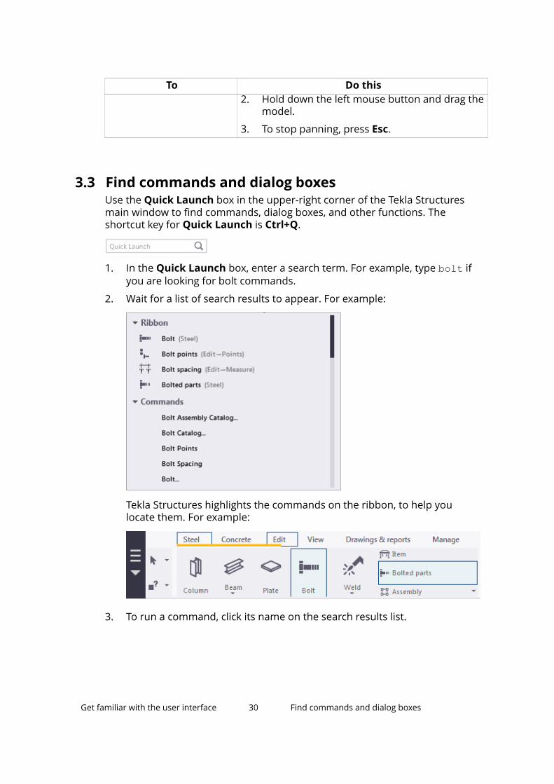
3.3 Find commands and dialog boxesUse the Quick Launch box in the upper-right corner of the Tekla Structuresmain window to find commands, dialog boxes, and other functions. Theshortcut key for Quick Launch is Ctrl+Q.
1. In the Quick Launch box, enter a search term. For example, type bolt ifyou are looking for bolt commands.
2. Wait for a list of search results to appear. For example:
Tekla Structures highlights the commands on the ribbon, to help youlocate them. For example:
3. To run a command, click its name on the search results list.
Get familiar with the user interface 30 Find commands and dialog boxes
Or press Enter to instantly run the first command on the list.
TIP If the list of search results is no longer visible, press Ctrl+Space toreactivate it.
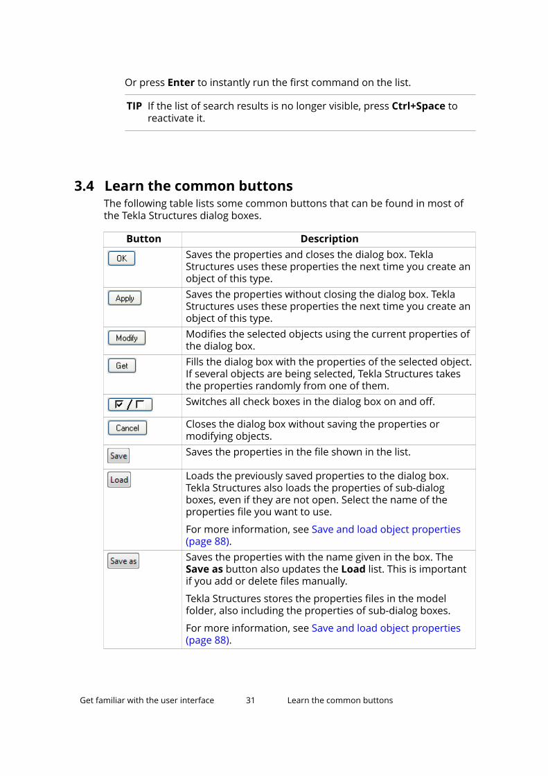
3.4 Learn the common buttonsThe following table lists some common buttons that can be found in most ofthe Tekla Structures dialog boxes.
Button DescriptionSaves the properties and closes the dialog box. TeklaStructures uses these properties the next time you create anobject of this type.Saves the properties without closing the dialog box. TeklaStructures uses these properties the next time you create anobject of this type.Modifies the selected objects using the current properties ofthe dialog box.Fills the dialog box with the properties of the selected object.If several objects are being selected, Tekla Structures takesthe properties randomly from one of them.Switches all check boxes in the dialog box on and off.
Closes the dialog box without saving the properties ormodifying objects.Saves the properties in the file shown in the list.
Loads the previously saved properties to the dialog box.Tekla Structures also loads the properties of sub-dialogboxes, even if they are not open. Select the name of theproperties file you want to use.
For more information, see Save and load object properties(page 88).Saves the properties with the name given in the box. TheSave as button also updates the Load list. This is importantif you add or delete files manually.
Tekla Structures stores the properties files in the modelfolder, also including the properties of sub-dialog boxes.
For more information, see Save and load object properties(page 88).
Get familiar with the user interface 31 Learn the common buttons
3.5 Change the appearance of the ribbonYou can change the order of ribbon tabs, choose how they are aligned, andeven hide some parts of the ribbon if you do not need them in your currentproject. For example, if you are only modeling steel parts, you can temporarilyhide the Concrete tab.
1. To change the order of tabs on the ribbon, drag and drop the tab titles.
2. To change how the tabs are aligned, right-click on the top bar of theribbon, select Navigation mode, and then select one of the options.
• Scroll visible: the ribbon movement is minimal when you switchbetween the tabs
• Align to left: the icons start from the left side of the ribbon
• Align to tab: the icons start from the left side of the current tab
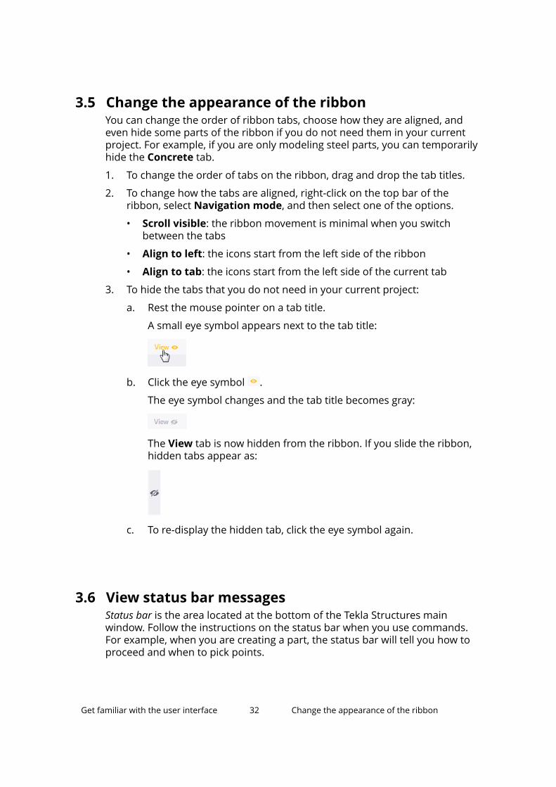
3. To hide the tabs that you do not need in your current project:
a. Rest the mouse pointer on a tab title.
A small eye symbol appears next to the tab title:
b. Click the eye symbol .
The eye symbol changes and the tab title becomes gray:
The View tab is now hidden from the ribbon. If you slide the ribbon,hidden tabs appear as:
c. To re-display the hidden tab, click the eye symbol again.
3.6 View status bar messagesStatus bar is the area located at the bottom of the Tekla Structures mainwindow. Follow the instructions on the status bar when you use commands.For example, when you are creating a part, the status bar will tell you how toproceed and when to pick points.
Get familiar with the user interface 32 Change the appearance of the ribbon
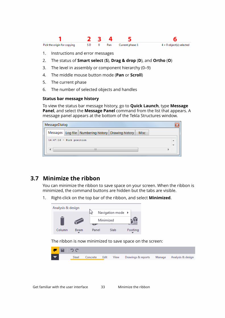
1. Instructions and error messages
2. The status of Smart select (S), Drag & drop (D), and Ortho (O)
3. The level in assembly or component hierarchy (0–9)
4. The middle mouse button mode (Pan or Scroll)
5. The current phase
6. The number of selected objects and handles
Status bar message history
To view the status bar message history, go to Quick Launch, type MessagePanel, and select the Message Panel command from the list that appears. Amessage panel appears at the bottom of the Tekla Structures window.
3.7 Minimize the ribbonYou can minimize the ribbon to save space on your screen. When the ribbon isminimized, the command buttons are hidden but the tabs are visible.
1. Right-click on the top bar of the ribbon, and select Minimized.
The ribbon is now minimized to save space on the screen:
Get familiar with the user interface 33 Minimize the ribbon
2. To access the commands when the ribbon is minimized, click a tab title.The ribbon becomes visible so that you can select a command.
3. To restore the ribbon, right-click on the top bar of the ribbon, and selectMinimized again.
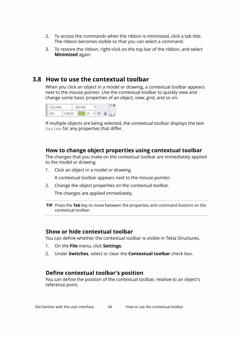
3.8 How to use the contextual toolbarWhen you click an object in a model or drawing, a contextual toolbar appearsnext to the mouse pointer. Use the contextual toolbar to quickly view andchange some basic properties of an object, view, grid, and so on.
If multiple objects are being selected, the contextual toolbar displays the textVaries for any properties that differ.
How to change object properties using contextual toolbarThe changes that you make on the contextual toolbar are immediately appliedto the model or drawing.
1. Click an object in a model or drawing.
A contextual toolbar appears next to the mouse pointer.
2. Change the object properties on the contextual toolbar.
The changes are applied immediately.
TIP Press the Tab key to move between the properties and command buttons on thecontextual toolbar.
Show or hide contextual toolbarYou can define whether the contextual toolbar is visible in Tekla Structures.
1. On the File menu, click Settings.
2. Under Switches, select or clear the Contextual toolbar check box.
Define contextual toolbar's positionYou can define the position of the contextual toolbar, relative to an object'sreference point.
Get familiar with the user interface 34 How to use the contextual toolbar
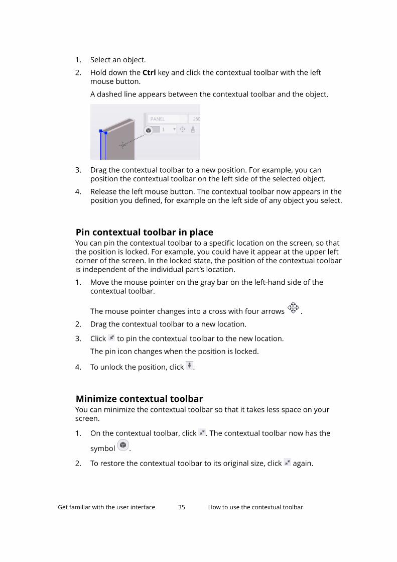
1. Select an object.
2. Hold down the Ctrl key and click the contextual toolbar with the leftmouse button.
A dashed line appears between the contextual toolbar and the object.
3. Drag the contextual toolbar to a new position. For example, you canposition the contextual toolbar on the left side of the selected object.
4. Release the left mouse button. The contextual toolbar now appears in theposition you defined, for example on the left side of any object you select.
Pin contextual toolbar in placeYou can pin the contextual toolbar to a specific location on the screen, so thatthe position is locked. For example, you could have it appear at the upper leftcorner of the screen. In the locked state, the position of the contextual toolbaris independent of the individual part’s location.
1. Move the mouse pointer on the gray bar on the left-hand side of thecontextual toolbar.
The mouse pointer changes into a cross with four arrows .
2. Drag the contextual toolbar to a new location.
3. Click to pin the contextual toolbar to the new location.
The pin icon changes when the position is locked.
4. To unlock the position, click .
Minimize contextual toolbarYou can minimize the contextual toolbar so that it takes less space on yourscreen.
1. On the contextual toolbar, click . The contextual toolbar now has the
symbol .
2. To restore the contextual toolbar to its original size, click again.
Get familiar with the user interface 35 How to use the contextual toolbar
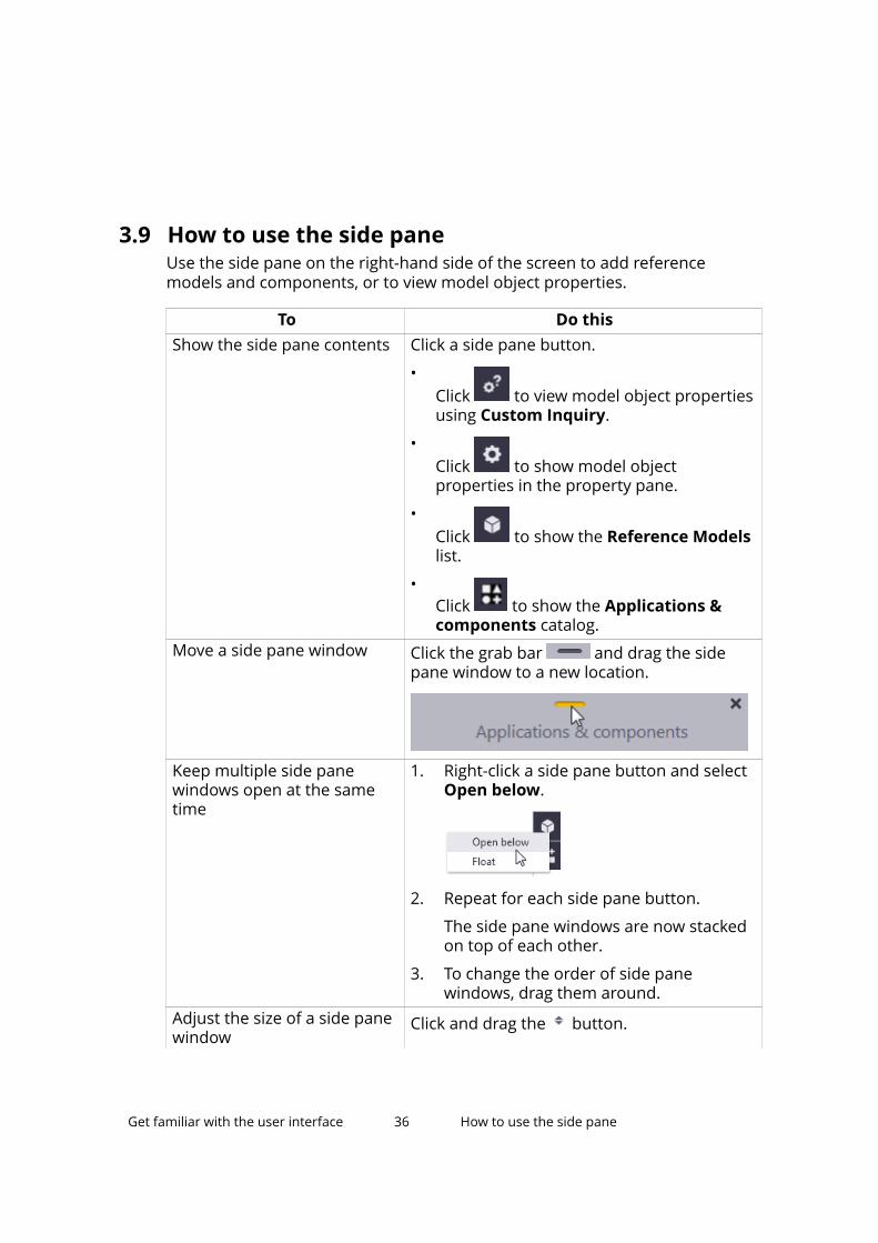
3.9 How to use the side paneUse the side pane on the right-hand side of the screen to add referencemodels and components, or to view model object properties.
To Do thisShow the side pane contents Click a side pane button.
•Click to view model object propertiesusing Custom Inquiry.
•Click to show model objectproperties in the property pane.
•Click to show the Reference Modelslist.
•Click to show the Applications &components catalog.
Move a side pane window Click the grab bar and drag the sidepane window to a new location.
Keep multiple side panewindows open at the sametime
1. Right-click a side pane button and selectOpen below.
2. Repeat for each side pane button.
The side pane windows are now stackedon top of each other.
3. To change the order of side panewindows, drag them around.
Adjust the size of a side panewindow
Click and drag the button.
Get familiar with the user interface 36 How to use the side pane
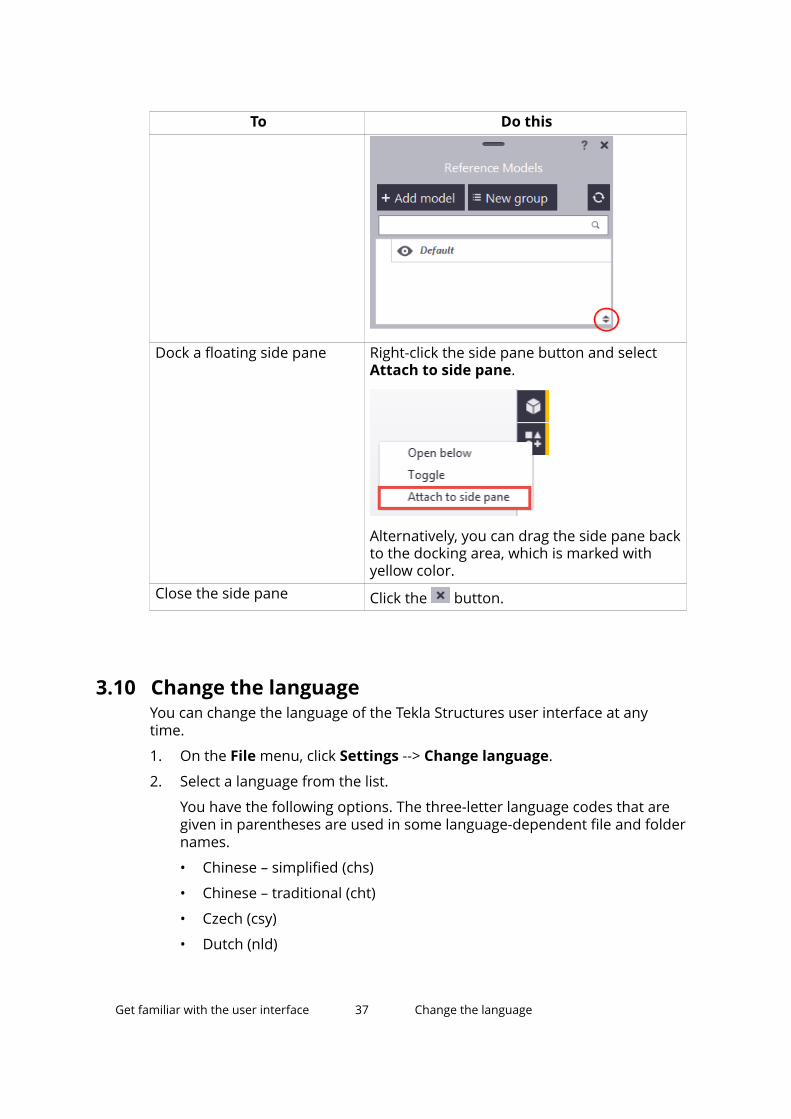
To Do this
Dock a floating side pane Right-click the side pane button and selectAttach to side pane.
Alternatively, you can drag the side pane backto the docking area, which is marked withyellow color.
Close the side pane Click the button.
3.10 Change the languageYou can change the language of the Tekla Structures user interface at anytime.
1. On the File menu, click Settings --> Change language.
2. Select a language from the list.
You have the following options. The three-letter language codes that aregiven in parentheses are used in some language-dependent file and foldernames.
• Chinese – simplified (chs)
• Chinese – traditional (cht)
• Czech (csy)
• Dutch (nld)
Get familiar with the user interface 37 Change the language
• English (enu)
• French (fra)
• German (deu)
• Hungarian (hun)
• Italian (ita)
• Japanese (jpn)
• Korean (kor)
• Polish (plk)
• Portuguese (ptg)
• Portuguese – Brazilian (ptb)
• Russian (rus)
• Spanish (esp)
3. Click OK.
4. Restart Tekla Structures for the change to take effect.
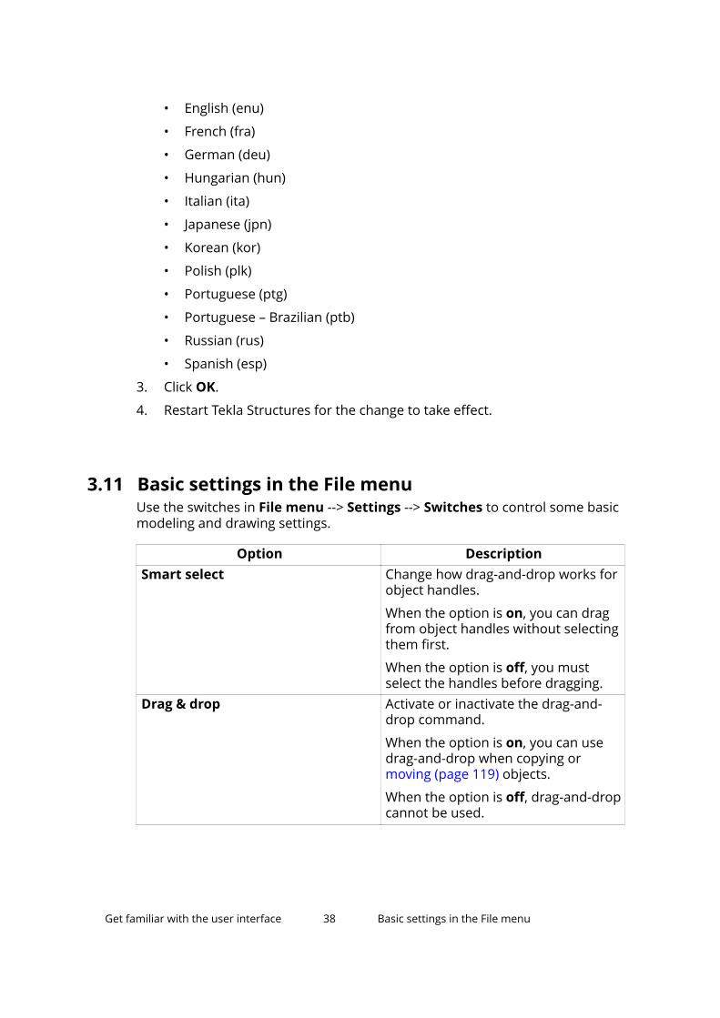
3.11 Basic settings in the File menuUse the switches in File menu --> Settings --> Switches to control some basicmodeling and drawing settings.
Option DescriptionSmart select Change how drag-and-drop works for
object handles.
When the option is on, you can dragfrom object handles without selectingthem first.
When the option is off, you mustselect the handles before dragging.
Drag & drop Activate or inactivate the drag-and-drop command.
When the option is on, you can usedrag-and-drop when copying ormoving (page 119) objects.
When the option is off, drag-and-dropcannot be used.
Get familiar with the user interface 38 Basic settings in the File menu
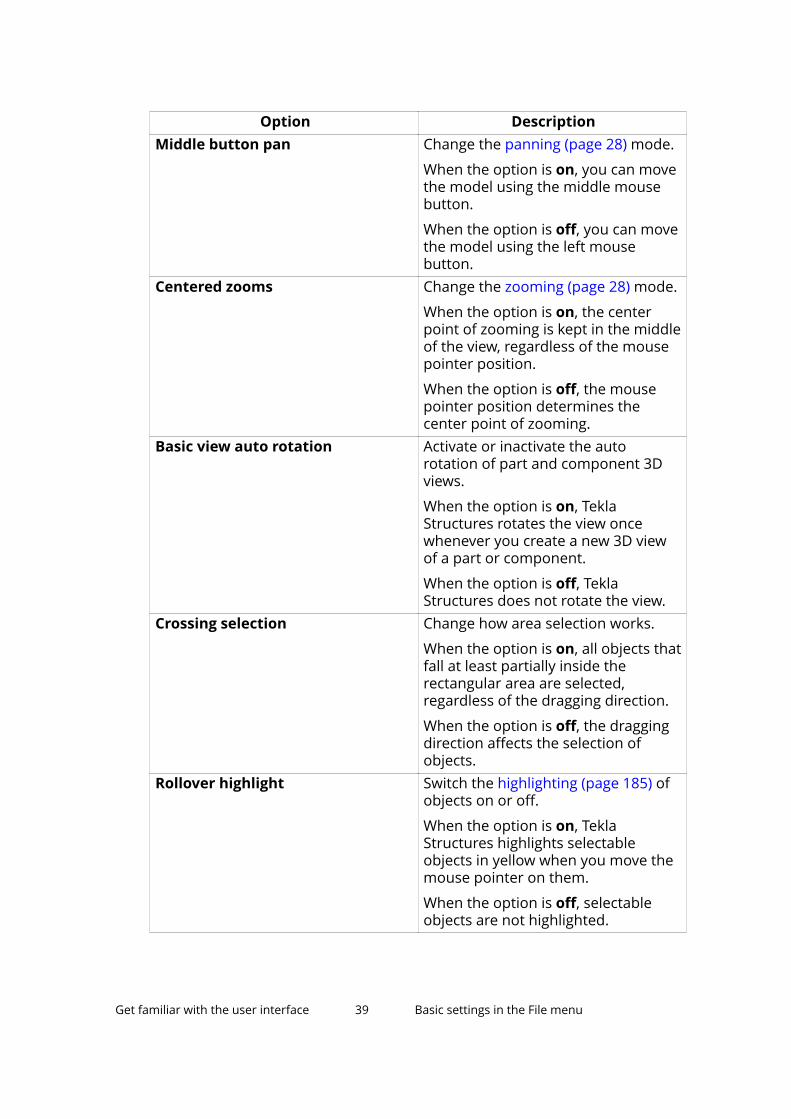
Option DescriptionMiddle button pan Change the panning (page 28) mode.
When the option is on, you can movethe model using the middle mousebutton.
When the option is off, you can movethe model using the left mousebutton.
Centered zooms Change the zooming (page 28) mode.
When the option is on, the centerpoint of zooming is kept in the middleof the view, regardless of the mousepointer position.
When the option is off, the mousepointer position determines thecenter point of zooming.
Basic view auto rotation Activate or inactivate the autorotation of part and component 3Dviews.
When the option is on, TeklaStructures rotates the view oncewhenever you create a new 3D viewof a part or component.
When the option is off, TeklaStructures does not rotate the view.
Crossing selection Change how area selection works.
When the option is on, all objects thatfall at least partially inside therectangular area are selected,regardless of the dragging direction.
When the option is off, the draggingdirection affects the selection ofobjects.
Rollover highlight Switch the highlighting (page 185) ofobjects on or off.
When the option is on, TeklaStructures highlights selectableobjects in yellow when you move themouse pointer on them.
When the option is off, selectableobjects are not highlighted.
Get familiar with the user interface 39 Basic settings in the File menu
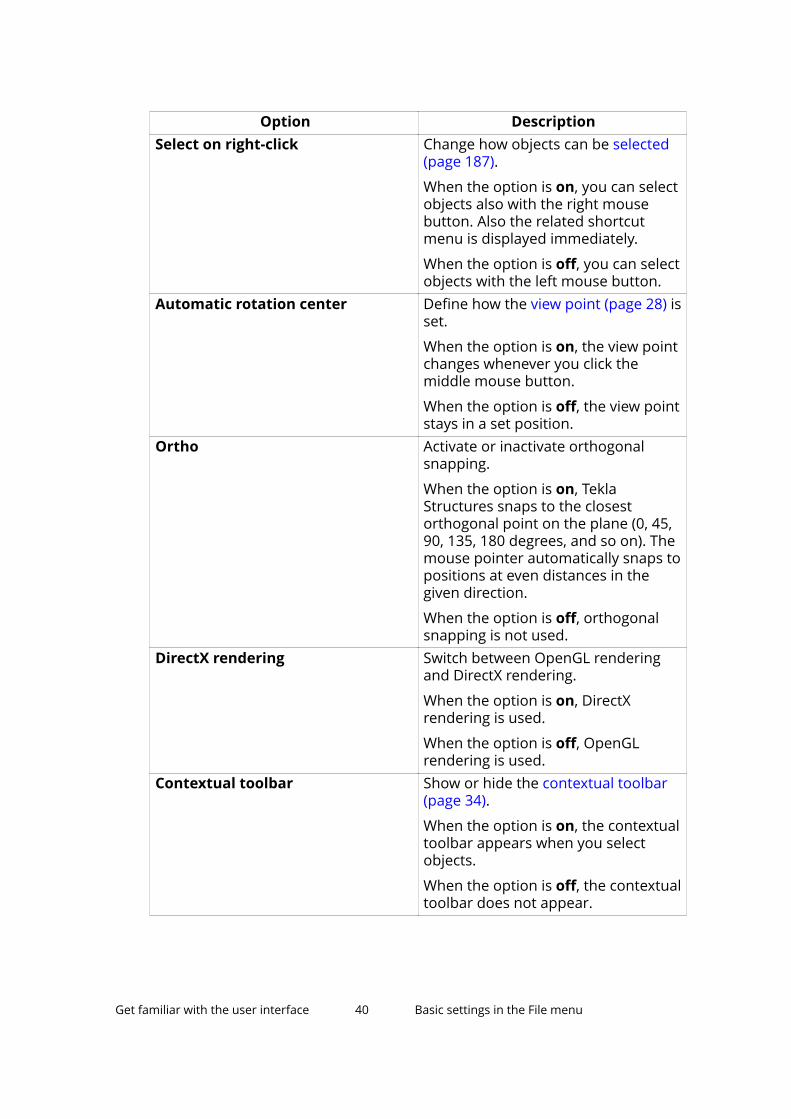
Option DescriptionSelect on right-click Change how objects can be selected
(page 187).
When the option is on, you can selectobjects also with the right mousebutton. Also the related shortcutmenu is displayed immediately.
When the option is off, you can selectobjects with the left mouse button.
Automatic rotation center Define how the view point (page 28) isset.
When the option is on, the view pointchanges whenever you click themiddle mouse button.
When the option is off, the view pointstays in a set position.
Ortho Activate or inactivate orthogonalsnapping.
When the option is on, TeklaStructures snaps to the closestorthogonal point on the plane (0, 45,90, 135, 180 degrees, and so on). Themouse pointer automatically snaps topositions at even distances in thegiven direction.
When the option is off, orthogonalsnapping is not used.
DirectX rendering Switch between OpenGL renderingand DirectX rendering.
When the option is on, DirectXrendering is used.
When the option is off, OpenGLrendering is used.
Contextual toolbar Show or hide the contextual toolbar(page 34).
When the option is on, the contextualtoolbar appears when you selectobjects.
When the option is off, the contextualtoolbar does not appear.
Get familiar with the user interface 40 Basic settings in the File menu
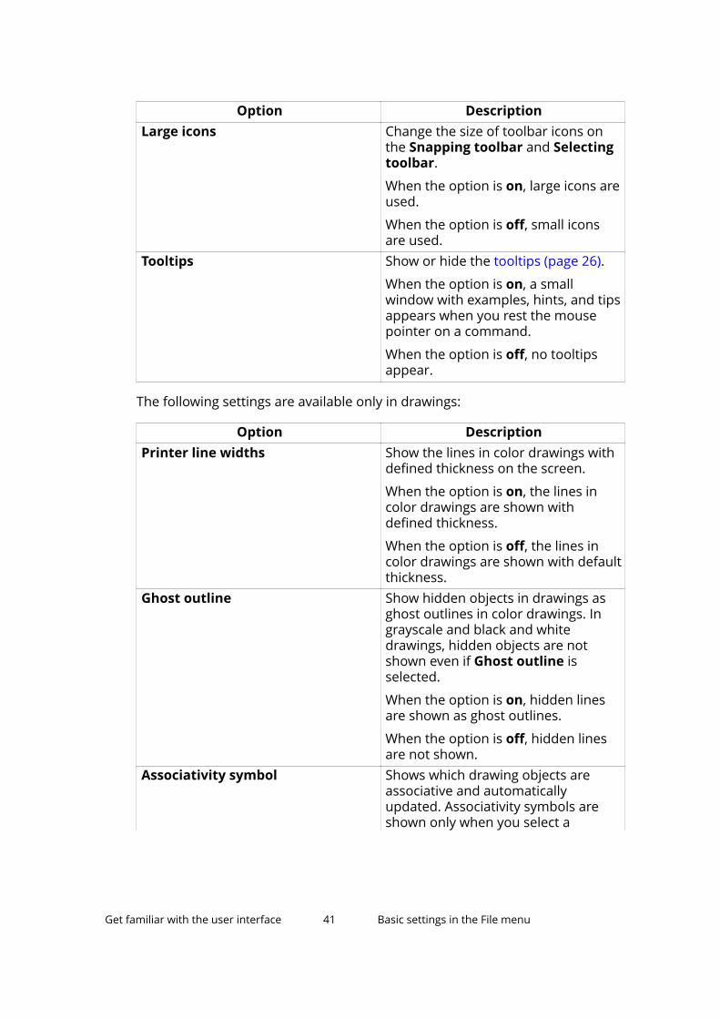
Option DescriptionLarge icons Change the size of toolbar icons on
the Snapping toolbar and Selectingtoolbar.
When the option is on, large icons areused.
When the option is off, small iconsare used.
Tooltips Show or hide the tooltips (page 26).
When the option is on, a smallwindow with examples, hints, and tipsappears when you rest the mousepointer on a command.
When the option is off, no tooltipsappear.
The following settings are available only in drawings:
Option DescriptionPrinter line widths Show the lines in color drawings with
defined thickness on the screen.
When the option is on, the lines incolor drawings are shown withdefined thickness.
When the option is off, the lines incolor drawings are shown with defaultthickness.
Ghost outline Show hidden objects in drawings asghost outlines in color drawings. Ingrayscale and black and whitedrawings, hidden objects are notshown even if Ghost outline isselected.
When the option is on, hidden linesare shown as ghost outlines.
When the option is off, hidden linesare not shown.
Associativity symbol Shows which drawing objects areassociative and automaticallyupdated. Associativity symbols areshown only when you select a
Get familiar with the user interface 41 Basic settings in the File menu
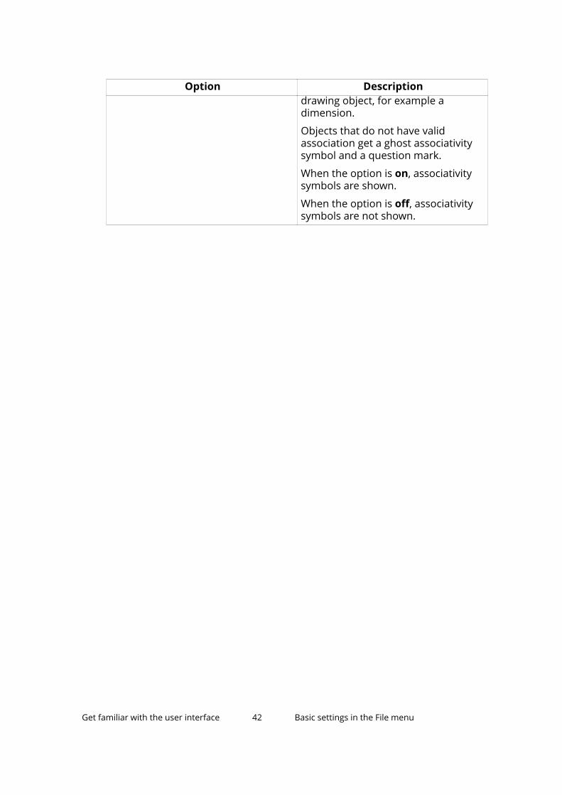
Option Descriptiondrawing object, for example adimension.
Objects that do not have validassociation get a ghost associativitysymbol and a question mark.
When the option is on, associativitysymbols are shown.
When the option is off, associativitysymbols are not shown.
Get familiar with the user interface 42 Basic settings in the File menu
4 Set up the workspace
Before starting to model, check that your Tekla Structures workspace is set upcorrectly.
1. Define the units and decimals you will use. (page 43)
2. Modify the grid to suit your needs. (page 44) Create a modular grid ifneeded.
3. Create some views (page 50) to examine the model from differentangles and elevations.
4. Resize the work area to suit your project. (page 64)
5. Get familiar with the coordinate system (page 66). If you are modelingsloped structures, shift the work plane accordingly. (page 67)
4.1 Change units and decimalsYou can define which units and how many decimals Tekla Structures uses. Thesettings are model-specific. Note that these settings do not have any effect ondrawings or reports, or on the Inquire and Measure tools.
1. On the File menu, click Settings --> Options, and go to the Units anddecimals settings.
2. Modify the units and decimals to suit your needs.
The number located to the right of each option indicates the number ofdecimals. The number of decimals affects the input and storage accuracy.Always use a sufficient number of decimals.
• The settings on the Modeling tab affect the data that is used when youare modeling, for example copying, moving, creating grids, creatingpoints, and so on.
• The settings on the Catalogs tab affect the data stored in the profileand material catalogs.
• The settings on the Analysis results tab affect the output data.
Set up the workspace 43 Change units and decimals
3. Click OK to save the changes.
4.2 Create grids and grid linesA grid represents a three-dimensional complex of horizontal and verticalplanes. The grid is shown on the view plane using dash-and-dot lines. Usegrids as an aid in locating objects in a model. You can make grids and grid linesact magnetically so that the objects on the grid lines follow if you move thegrid line.
• Create a grid (page 45)
• Modify a grid (page 46)
• Add a single grid line (page 47)
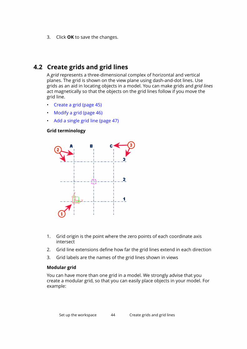
Grid terminology
1. Grid origin is the point where the zero points of each coordinate axisintersect
2. Grid line extensions define how far the grid lines extend in each direction
3. Grid labels are the names of the grid lines shown in views
Modular grid
You can have more than one grid in a model. We strongly advise that youcreate a modular grid, so that you can easily place objects in your model. Forexample:
Set up the workspace 44 Create grids and grid lines
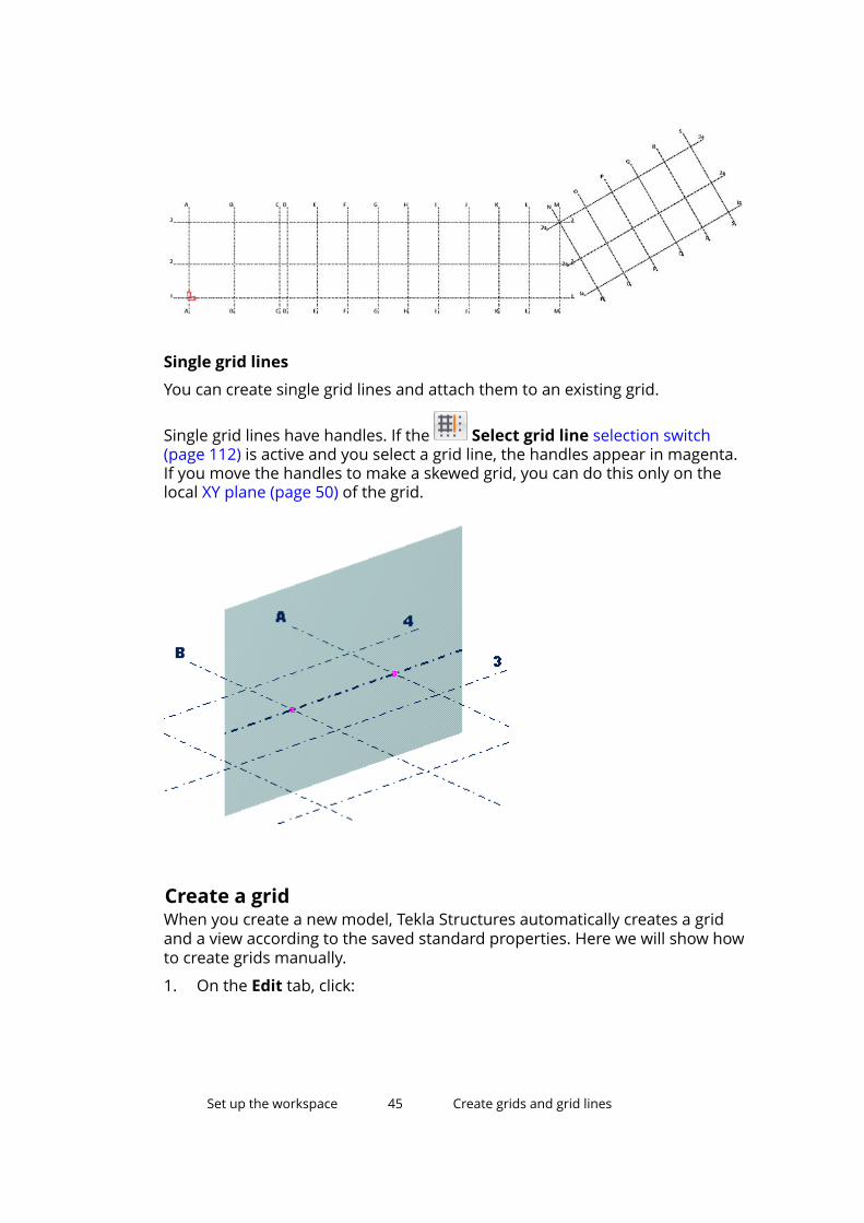
Single grid lines
You can create single grid lines and attach them to an existing grid.
Single grid lines have handles. If the Select grid line selection switch(page 112) is active and you select a grid line, the handles appear in magenta.If you move the handles to make a skewed grid, you can do this only on thelocal XY plane (page 50) of the grid.
Create a gridWhen you create a new model, Tekla Structures automatically creates a gridand a view according to the saved standard properties. Here we will show howto create grids manually.
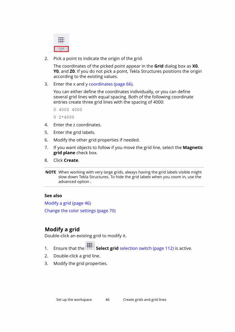
1. On the Edit tab, click:
Set up the workspace 45 Create grids and grid lines
2. Pick a point to indicate the origin of the grid.
The coordinates of the picked point appear in the Grid dialog box as X0,Y0, and Z0. If you do not pick a point, Tekla Structures positions the originaccording to the existing values.
3. Enter the x and y coordinates (page 66).
You can either define the coordinates individually, or you can defineseveral grid lines with equal spacing. Both of the following coordinateentries create three grid lines with the spacing of 4000:
0 4000 40000 2*4000
4. Enter the z coordinates.
5. Enter the grid labels.
6. Modify the other grid properties if needed.
7. If you want objects to follow if you move the grid line, select the Magneticgrid plane check box.
8. Click Create.
NOTE When working with very large grids, always having the grid labels visible mightslow down Tekla Structures. To hide the grid labels when you zoom in, use theadvanced option .
See also
Modify a grid (page 46)
Change the color settings (page 70)
Modify a gridDouble-click an existing grid to modify it.
1. Ensure that the Select grid selection switch (page 112) is active.
2. Double-click a grid line.
3. Modify the grid properties.
Set up the workspace 46 Create grids and grid lines
4. If you have attached additional grid lines to the grid and you want topreserve them, clear the check boxes next to the Coordinate boxes.
Otherwise Tekla Structures deletes all single grid lines (page 44) attachedto the grid.
5. Click Modify to save the changes.
See also
Change the color settings (page 70)
Modify a single grid line (page 48)
Delete a gridWhen you delete an entire grid, ensure that you do not have any other objectsselected. Otherwise Tekla Structures only deletes the objects, not the grid.
1. Ensure that only the Select grid selection switch (page 112) is active.
2. Select the grid.
3. Right-click and select Delete from the pop-up menu.
4. Confirm that you want to delete the grid.
See also
Deleting a single grid line (page 50)
Add a single grid lineYou can add new grid lines either between existing grid lines or between twofreely chosen points that you define in the model.
Add a grid line between existing grid linesYou can add new grid lines between existing grid lines.
1. Ensure that the Direct modification switch is active.
2. Ensure that the Select grid selection switch (page 112) is active.
3. Select an existing grid to attach the grid line to.
Set up the workspace 47 Create grids and grid lines
4. Click the symbol between two existing grid lines or outside the grid.
Tekla Structures creates the grid line and gives it a label using the labels ofthe adjacent grid lines. For example, a new grid line between the grid lines1 and 2 receives the label 12*.
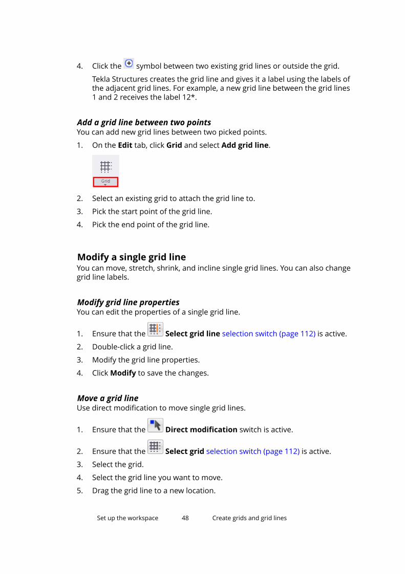
Add a grid line between two pointsYou can add new grid lines between two picked points.
1. On the Edit tab, click Grid and select Add grid line.
2. Select an existing grid to attach the grid line to.
3. Pick the start point of the grid line.
4. Pick the end point of the grid line.
Modify a single grid lineYou can move, stretch, shrink, and incline single grid lines. You can also changegrid line labels.
Modify grid line propertiesYou can edit the properties of a single grid line.
1. Ensure that the Select grid line selection switch (page 112) is active.
2. Double-click a grid line.
3. Modify the grid line properties.
4. Click Modify to save the changes.
Move a grid lineUse direct modification to move single grid lines.
1. Ensure that the Direct modification switch is active.
2. Ensure that the Select grid selection switch (page 112) is active.
3. Select the grid.
4. Select the grid line you want to move.
5. Drag the grid line to a new location.
Set up the workspace 48 Create grids and grid lines
You can also use the keyboard to enter a numeric location.
To start with the negative sign (-), use the numeric keypad. To enter anabsolute coordinate, first enter $, then the value. Press Enter to confirm.
Stretch, shrink, or incline a grid lineUse direct modification to stretch, shrink, or incline single grid lines.
1. Ensure that the Direct modification switch is active.
2. Ensure that the Select grid selection switch (page 112) is active.
3. Select the grid.
4. Select the grid line.
5. Drag a grid line handle to a new location.
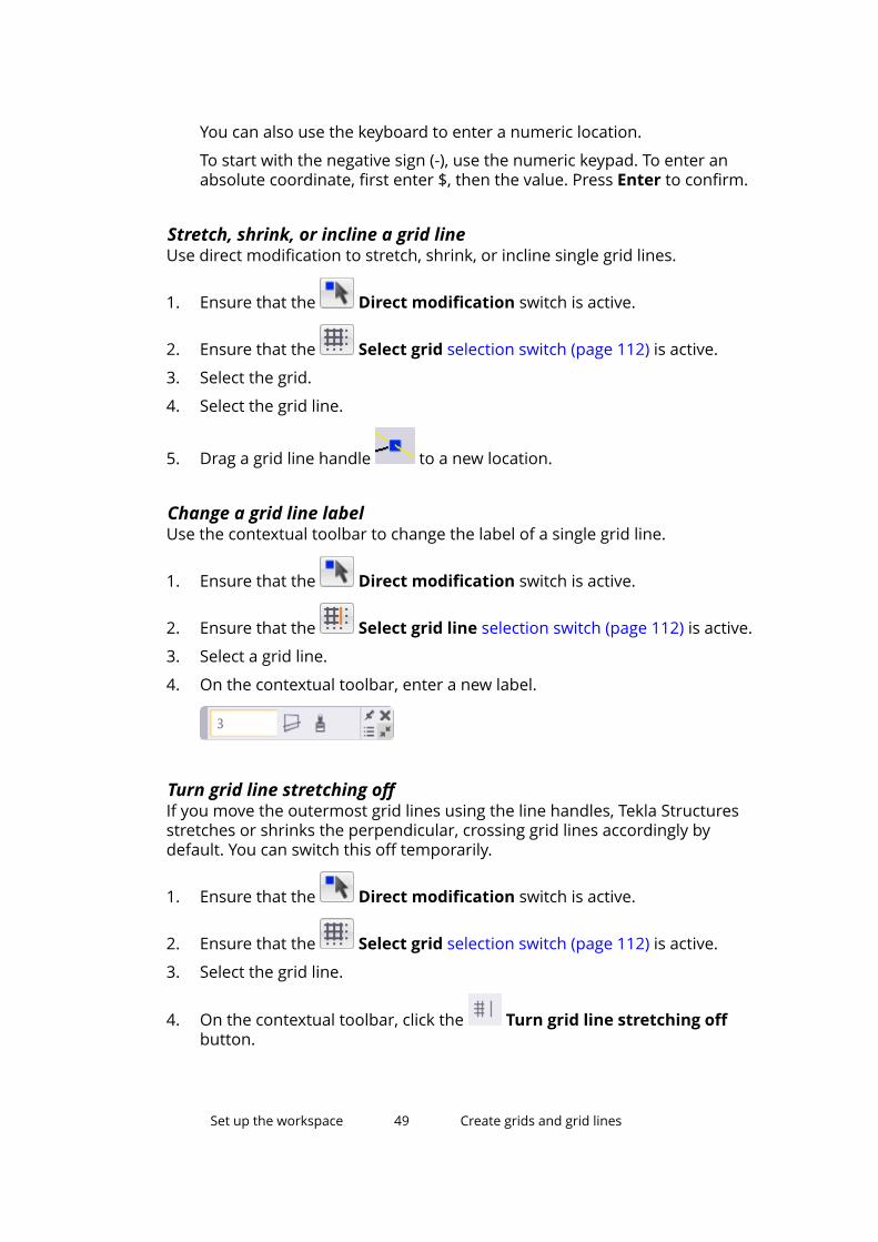
Change a grid line labelUse the contextual toolbar to change the label of a single grid line.
1. Ensure that the Direct modification switch is active.
2. Ensure that the Select grid line selection switch (page 112) is active.
3. Select a grid line.
4. On the contextual toolbar, enter a new label.
Turn grid line stretching offIf you move the outermost grid lines using the line handles, Tekla Structuresstretches or shrinks the perpendicular, crossing grid lines accordingly bydefault. You can switch this off temporarily.
1. Ensure that the Direct modification switch is active.
2. Ensure that the Select grid selection switch (page 112) is active.
3. Select the grid line.
4. On the contextual toolbar, click the Turn grid line stretching offbutton.
Set up the workspace 49 Create grids and grid lines
Deleting a single grid lineYou can delete grid lines in two different ways. The easiest way is by usingdirect modification.
Delete a grid line using direct modificationUse direct modification to quickly delete single grid lines.
1. Ensure that the Direct modification switch is active.
2. Select the grid line you want to delete.
3. Press Delete.
Delete a grid line (alternative method)This is the alternative way of deleting single grid lines.
1. Ensure that the Select grid line selection switch (page 112) is active.
2. Select the grid line you want to delete.
3. Ensure that you do not have any other objects selected.
If you also have other objects selected, Tekla Structures only deletes theobjects, not the grid line.
4. Right-click and select Delete from the pop-up menu.
5. Confirm that you want to delete the grid line.
4.3 Create model viewsA view is a representation of a model from a specific location. Each view isrepresented in its own window within Tekla Structures. Selecting a part in aview highlights the part in all open views.
• Create views (page 52)
• Open a view (page 61)
• Switch between views (page 63)
• Change the color settings (page 70)
View plane
Each view has a view plane on which the grids (page 44) are visible and pointsare represented as yellow crosses. Points that are located outside the viewplane are red. You can move the view plane (page 52) like any other object.
Set up the workspace 50 Create model views
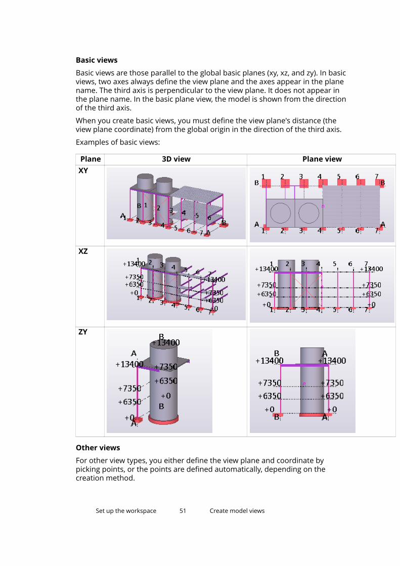
Basic views
Basic views are those parallel to the global basic planes (xy, xz, and zy). In basicviews, two axes always define the view plane and the axes appear in the planename. The third axis is perpendicular to the view plane. It does not appear inthe plane name. In the basic plane view, the model is shown from the directionof the third axis.
When you create basic views, you must define the view plane's distance (theview plane coordinate) from the global origin in the direction of the third axis.
Examples of basic views:
Plane 3D view Plane viewXY
XZ
ZY
Other views
For other view types, you either define the view plane and coordinate bypicking points, or the points are defined automatically, depending on thecreation method.
Set up the workspace 51 Create model views
Move the view planeYou can move the view plane like any other object. When you move it, TeklaStructures only uses the vector that is perpendicular to the view plane.
1. Click the view.
2. Right-click and select Move --> Linear.
3. Pick the start point of the translation vector, or enter its coordinates.
4. Pick the end point of the translation vector, or enter its coordinates.
5. Click Move to move the view plane.
Create viewsYou can create views of parts, components, and the entire model.
Create a basic view of the modelYou can create a basic view along two coordinate axes. Use this view for theoverall viewing of the model.
1. On the View tab, click New view --> Basic view.
2. Select a view plane from the Plane list.
3. In the Coordinate box, enter the view level.
This value defines the distance from the global origin.
4. Click Create.
Create a view using two pointsYou can create a view using two points you pick: the origin and a point in thehorizontal direction.
1. On the View tab, click New view --> Using two points.
2. Pick a point to indicate the origin of the view plane.
3. Pick a second point to indicate the direction of the x axis.
The y axis is perpendicular to the view plane on which you picked the firstpoint.
Set up the workspace 52 Create model views
Create a view using three pointsYou can create a view using three points you pick: the origin, a point in thehorizontal direction, and a point in the vertical direction.
1. On the View tab, click New view --> Using three points.
2. Pick a point to indicate the origin of the view plane.
3. Pick a second point to indicate the direction of the x axis.
4. Pick a third point to indicate the direction of the y axis.
Create a view of the work planeYou can create a view of the work plane using the current view properties.
• On the View tab, click New view --> On work plane.
Create grid viewsYou can create views along the grid lines you select.
Before you start, create a view that contains a grid, and check the gridproperties. If the grid properties are incorrect in some way, Tekla Structuresmay cut the views at the wrong elevations or they may be named incorrectly. Ifyou change the grid labels or the elevation or grids later on, the views will notbe automatically renamed.
1. Select the grid.
2. On the View tab, click New view --> Along grid lines.
3. Modify the grid view properties if needed.
a. In the Number of views list, select how many views you want tocreate.
b. In the View name prefix box, enter a prefix.
c. In the View properties list, define which view properties (applied orsaved) you want to use.
4. Click Create.
The Views dialog box opens.
5. Click the arrow buttons to move views from the Named views list to theVisible views list.
The views will not be visible until you move them to the Visible views list.
Set up the workspace 53 Create model views
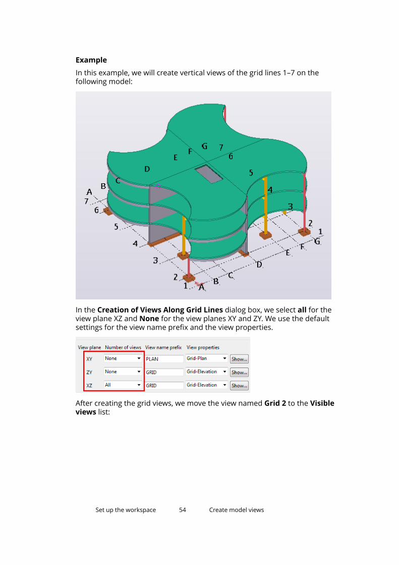
Example
In this example, we will create vertical views of the grid lines 1–7 on thefollowing model:
In the Creation of Views Along Grid Lines dialog box, we select all for theview plane XZ and None for the view planes XY and ZY. We use the defaultsettings for the view name prefix and the view properties.
After creating the grid views, we move the view named Grid 2 to the Visibleviews list:
Set up the workspace 54 Create model views
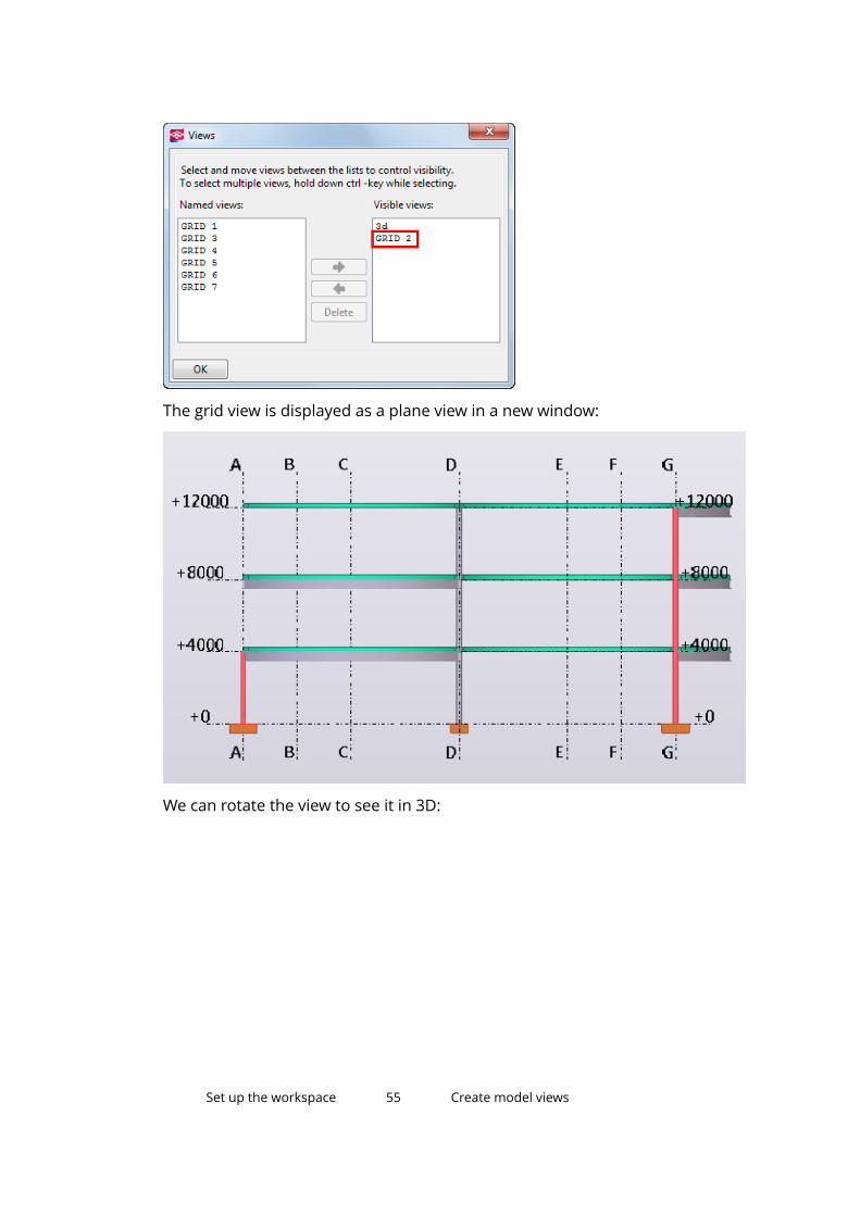
The grid view is displayed as a plane view in a new window:
We can rotate the view to see it in 3D:
Set up the workspace 55 Create model views
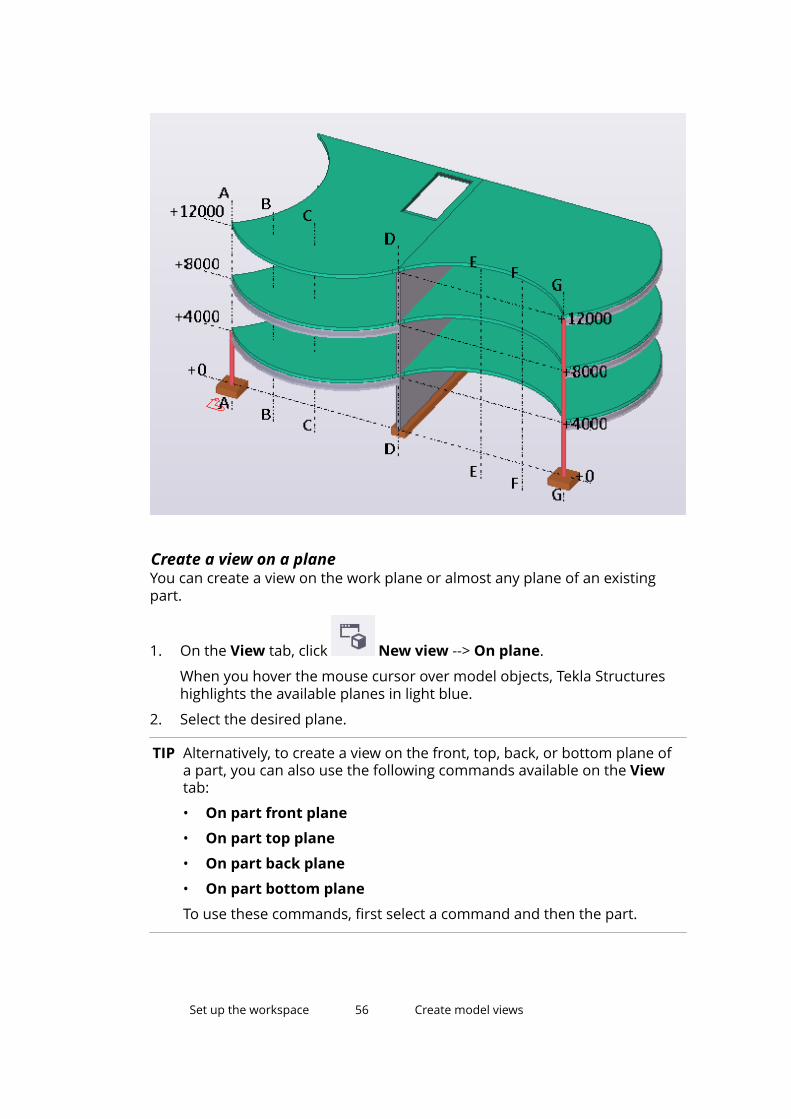
Create a view on a planeYou can create a view on the work plane or almost any plane of an existingpart.
1. On the View tab, click New view --> On plane.
When you hover the mouse cursor over model objects, Tekla Structureshighlights the available planes in light blue.
2. Select the desired plane.
TIP Alternatively, to create a view on the front, top, back, or bottom plane ofa part, you can also use the following commands available on the Viewtab:
• On part front plane
• On part top plane
• On part back plane
• On part bottom plane
To use these commands, first select a command and then the part.
Set up the workspace 56 Create model views
Create a 3D view of a partWhen you need to see a specific part clearly, create a 3D view of the part. Thepart is placed in the center of the view.
1. On the View tab, click New view --> 3D view of part.
2. Select the part.
Tekla Structures creates the view. The view plane y axis is the global z axisof the model. The x axis is the projection of the part's local x axis onto theglobal xy plane.
Create default part viewsYou can create four basic views of a part: front, top, end and perspective view.Tekla Structures creates these views all at once with the same command. Bydefault, the perspective view is a 3D view, and the front, top, and end views areplane views.
1. On the View tab, click New view --> Default part views.
2. Select the part.
Tekla Structures creates the four default views all at once.
Create an undeformed part viewYou can create a view that shows a deformed part in undeformed form. Thisonly works for beams and columns.
1. On the View tab, click New view --> Undeformed part view.
2. Select the part.
For example, select a warped beam. Tekla Structures displays the beam ina separate view in undeformed form.
Create a 3D view of a componentWhen you need to see a specific component clearly, create a 3D view of thecomponent. The component is placed in the center of the view.
1. On the View tab, click New view --> 3D view of component.
Set up the workspace 57 Create model views
2. Select the component.
Tekla Structures creates the view. The view plane y axis is the global z axisof the model. The x axis is the projection of the first secondary part local xaxis onto the global xy plane. Work area depth is 1 m in all directions.
Create default component viewsYou can create four basic views of a component: front, top, end andperspective view. Tekla Structures creates these views all at once with thesame command. By default, the perspective view is a 3D view, and the front,top, and end views are plane views.
1. On the View tab, click New view --> Default views of component.
2. Select the component.
Tekla Structures creates the four default views all at once.
Create a surface viewUse the CreateSurfaceView macro to create an automatically aligned surfaceview. This can be useful when modeling bolt groups, stiffener plates, and holepenetrations on complex geometry.
1. Click the Applications & components button in the side pane toopen the Applications & components catalog.
2. Click the arrow next to Applications to open the applications list.
3. Double-click CreateSurfaceView to start the macro.
4. Select the surface of the part.
Set up the workspace 58 Create model views
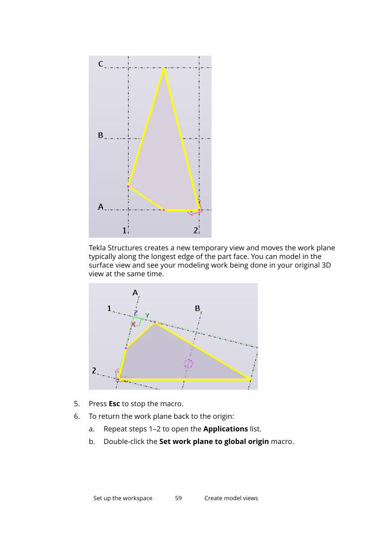
Tekla Structures creates a new temporary view and moves the work planetypically along the longest edge of the part face. You can model in thesurface view and see your modeling work being done in your original 3Dview at the same time.
5. Press Esc to stop the macro.
6. To return the work plane back to the origin:
a. Repeat steps 1–2 to open the Applications list.
b. Double-click the Set work plane to global origin macro.
Set up the workspace 59 Create model views
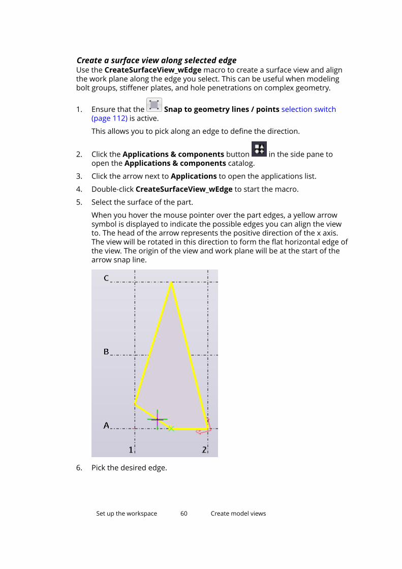
Create a surface view along selected edgeUse the CreateSurfaceView_wEdge macro to create a surface view and alignthe work plane along the edge you select. This can be useful when modelingbolt groups, stiffener plates, and hole penetrations on complex geometry.
1. Ensure that the Snap to geometry lines / points selection switch(page 112) is active.
This allows you to pick along an edge to define the direction.
2. Click the Applications & components button in the side pane toopen the Applications & components catalog.
3. Click the arrow next to Applications to open the applications list.
4. Double-click CreateSurfaceView_wEdge to start the macro.
5. Select the surface of the part.
When you hover the mouse pointer over the part edges, a yellow arrowsymbol is displayed to indicate the possible edges you can align the viewto. The head of the arrow represents the positive direction of the x axis.The view will be rotated in this direction to form the flat horizontal edge ofthe view. The origin of the view and work plane will be at the start of thearrow snap line.
6. Pick the desired edge.
Set up the workspace 60 Create model views
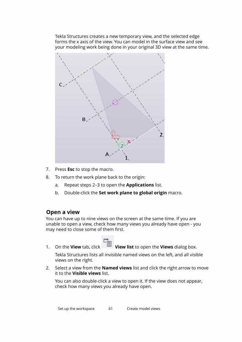
Tekla Structures creates a new temporary view, and the selected edgeforms the x axis of the view. You can model in the surface view and seeyour modeling work being done in your original 3D view at the same time.
7. Press Esc to stop the macro.
8. To return the work plane back to the origin:
a. Repeat steps 2–3 to open the Applications list.
b. Double-click the Set work plane to global origin macro.
Open a viewYou can have up to nine views on the screen at the same time. If you areunable to open a view, check how many views you already have open - youmay need to close some of them first.
1. On the View tab, click View list to open the Views dialog box.
Tekla Structures lists all invisible named views on the left, and all visibleviews on the right.
2. Select a view from the Named views list and click the right arrow to moveit to the Visible views list.
You can also double-click a view to open it. If the view does not appear,check how many views you already have open.
Set up the workspace 61 Create model views
3. To open multiple views, use the Shift and Ctrl keys when you select viewsfrom the list.
See also
Save a view (page 62)
Switch between views (page 63)
Save a viewIf you need to re-open views later on, give each view a unique name. Whenyou exit the model, Tekla Structures only saves the named views. Temporaryviews disappear when you close them.
Before you start, create one or more views (page 52) in the model.
1. Double-click the view to open the View Properties dialog box.
2. Enter a unique name in the name box.
Temporary views have a default name in parentheses. Do not useparentheses when naming a view, or the view will not be saved for lateruse.
NOTE In multi-user mode, it is very important to give views uniquenames. If several users have different views with the same name,the view settings of one user may accidentally override thesettings of another user.
3. Click Modify.
Tekla Structures will automatically save all named views when you closethe model.
Modify a viewYou can modify a view simply by double-clicking it.
1. Double-click the view to open the View Properties dialog box.
2. Modify the view properties.
3. Click Modify.
See also
Move the view plane (page 52)
Set up the workspace 62 Create model views
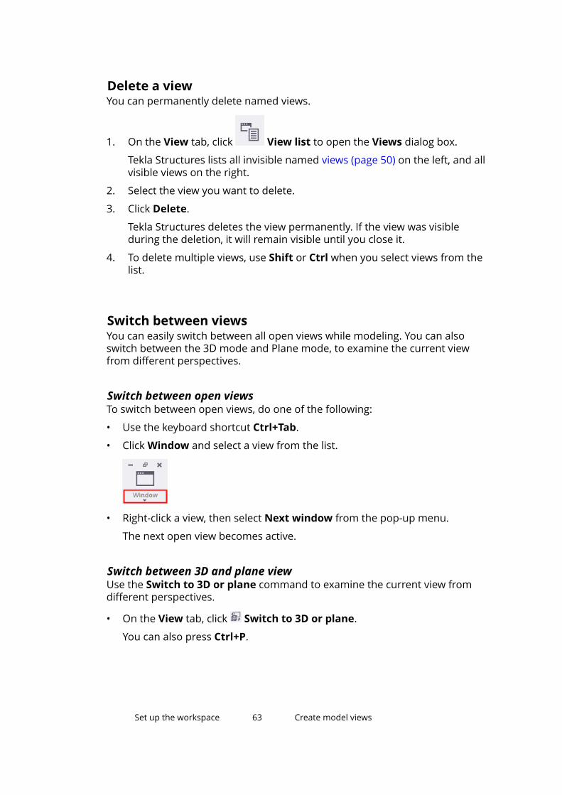
Delete a viewYou can permanently delete named views.
1. On the View tab, click View list to open the Views dialog box.
Tekla Structures lists all invisible named views (page 50) on the left, and allvisible views on the right.
2. Select the view you want to delete.
3. Click Delete.
Tekla Structures deletes the view permanently. If the view was visibleduring the deletion, it will remain visible until you close it.
4. To delete multiple views, use Shift or Ctrl when you select views from thelist.
Switch between viewsYou can easily switch between all open views while modeling. You can alsoswitch between the 3D mode and Plane mode, to examine the current viewfrom different perspectives.
Switch between open viewsTo switch between open views, do one of the following:
• Use the keyboard shortcut Ctrl+Tab.
• Click Window and select a view from the list.
• Right-click a view, then select Next window from the pop-up menu.
The next open view becomes active.
Switch between 3D and plane viewUse the Switch to 3D or plane command to examine the current view fromdifferent perspectives.
• On the View tab, click Switch to 3D or plane.
You can also press Ctrl+P.
Set up the workspace 63 Create model views
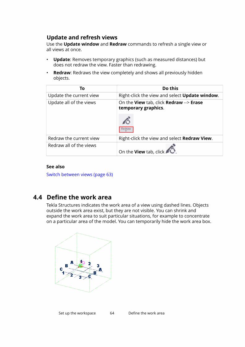
Update and refresh viewsUse the Update window and Redraw commands to refresh a single view orall views at once.
• Update: Removes temporary graphics (such as measured distances) butdoes not redraw the view. Faster than redrawing.
• Redraw: Redraws the view completely and shows all previously hiddenobjects.
To Do thisUpdate the current view Right-click the view and select Update window.Update all of the views On the View tab, click Redraw --> Erase
temporary graphics.
Redraw the current view Right-click the view and select Redraw View.Redraw all of the views
On the View tab, click .
See also
Switch between views (page 63)
4.4 Define the work areaTekla Structures indicates the work area of a view using dashed lines. Objectsoutside the work area exist, but they are not visible. You can shrink andexpand the work area to suit particular situations, for example to concentrateon a particular area of the model. You can temporarily hide the work area box.
Set up the workspace 64 Define the work area
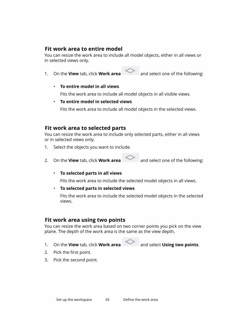
Fit work area to entire modelYou can resize the work area to include all model objects, either in all views orin selected views only.
1. On the View tab, click Work area and select one of the following:
• To entire model in all views
Fits the work area to include all model objects in all visible views.
• To entire model in selected views
Fits the work area to include all model objects in the selected views.
Fit work area to selected partsYou can resize the work area to include only selected parts, either in all viewsor in selected views only.
1. Select the objects you want to include.
2. On the View tab, click Work area and select one of the following:
• To selected parts in all views
Fits the work area to include the selected model objects in all views.
• To selected parts in selected views
Fits the work area to include the selected model objects in the selectedviews.
Fit work area using two pointsYou can resize the work area based on two corner points you pick on the viewplane. The depth of the work area is the same as the view depth.
1. On the View tab, click Work area and select Using two points.
2. Pick the first point.
3. Pick the second point.
Set up the workspace 65 Define the work area
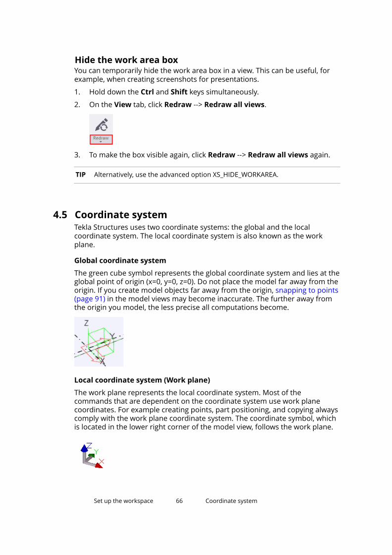
Hide the work area boxYou can temporarily hide the work area box in a view. This can be useful, forexample, when creating screenshots for presentations.
1. Hold down the Ctrl and Shift keys simultaneously.
2. On the View tab, click Redraw --> Redraw all views.
3. To make the box visible again, click Redraw --> Redraw all views again.
TIP Alternatively, use the advanced option XS_HIDE_WORKAREA.
4.5 Coordinate systemTekla Structures uses two coordinate systems: the global and the localcoordinate system. The local coordinate system is also known as the workplane.
Global coordinate system
The green cube symbol represents the global coordinate system and lies at theglobal point of origin (x=0, y=0, z=0). Do not place the model far away from theorigin. If you create model objects far away from the origin, snapping to points(page 91) in the model views may become inaccurate. The further away fromthe origin you model, the less precise all computations become.
Local coordinate system (Work plane)
The work plane represents the local coordinate system. Most of thecommands that are dependent on the coordinate system use work planecoordinates. For example creating points, part positioning, and copying alwayscomply with the work plane coordinate system. The coordinate symbol, whichis located in the lower right corner of the model view, follows the work plane.
Set up the workspace 66 Coordinate system
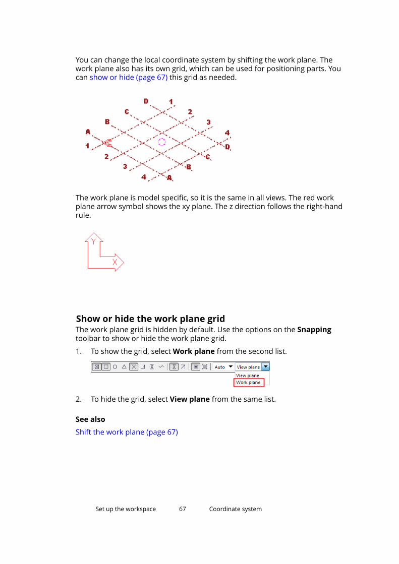
You can change the local coordinate system by shifting the work plane. Thework plane also has its own grid, which can be used for positioning parts. Youcan show or hide (page 67) this grid as needed.
The work plane is model specific, so it is the same in all views. The red workplane arrow symbol shows the xy plane. The z direction follows the right-handrule.
Show or hide the work plane gridThe work plane grid is hidden by default. Use the options on the Snappingtoolbar to show or hide the work plane grid.
1. To show the grid, select Work plane from the second list.
2. To hide the grid, select View plane from the same list.
See also
Shift the work plane (page 67)
Set up the workspace 67 Coordinate system
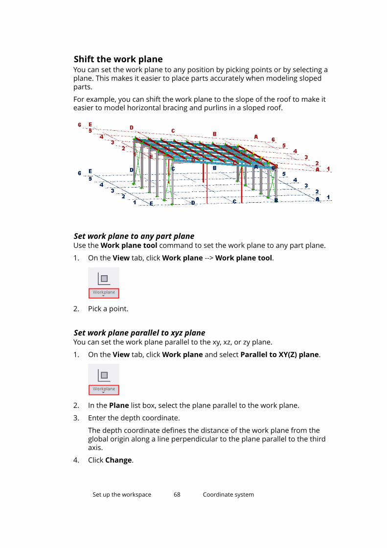
Shift the work planeYou can set the work plane to any position by picking points or by selecting aplane. This makes it easier to place parts accurately when modeling slopedparts.
For example, you can shift the work plane to the slope of the roof to make iteasier to model horizontal bracing and purlins in a sloped roof.
Set work plane to any part planeUse the Work plane tool command to set the work plane to any part plane.
1. On the View tab, click Work plane --> Work plane tool.
2. Pick a point.
Set work plane parallel to xyz planeYou can set the work plane parallel to the xy, xz, or zy plane.
1. On the View tab, click Work plane and select Parallel to XY(Z) plane.
2. In the Plane list box, select the plane parallel to the work plane.
3. Enter the depth coordinate.
The depth coordinate defines the distance of the work plane from theglobal origin along a line perpendicular to the plane parallel to the thirdaxis.
4. Click Change.
Set up the workspace 68 Coordinate system
Set work plane using one pointYou can set the work plane using one picked point. The work plane staysparallel to the current work plane, but moves it to a new position. The x and ydirections are unchanged.
1. On the View tab, click Work plane and select Using one point.
2. Pick the new position of the work plane.
Set work plane using two pointsYou can set the work plane using two picked points. The first point you pick isthe origin, the second defines the x direction of the work plane. The y directionremains the same as the previous work plane.
1. On the View tab, click Work plane and select Using two points.
2. Pick the origin of the work plane.
3. Pick a point in the work plane, in the positive x direction.
Set work plane using three pointsYou can set the work plane using three picked points. The first point you pick isthe origin, the second defines the x direction, and the third defines the ydirection of the work plane. Tekla Structures fixes the z direction according tothe right-hand rule.
1. On the View tab, click Work plane and select Using three points.
2. Pick the origin for the work plane.
3. Pick a point in the positive x direction.
4. Pick a point in the positive y direction.
Set up the workspace 69 Coordinate system
Set work plane parallel to view planeYou can set the work plane to be the same as the view plane of a selectedview.
1. On the View tab, click Work plane and select Parallel to view plane.
2. Select the view.
Restore the default work planeRemember to change back to the default work plane when you have finishedmodeling sloped structures.
1. On the View tab, click Work plane --> Parallel to XY(Z) plane.
2. In the Plane list, select XY.
3. In the Depth coordinate box, enter 0.
4. Click Change.
4.6 Change the color settingsYou can define which color you want to use for dimensions, labels,background, and grid lines in the model. For example, if you set thebackground color to black, you may need to adjust the other color settings aswell to ensure that the text and dimensions will be visible.
Change the color settings in the Advanced Options dialog box using RGBvalues on a scale of 0.0 to 1.0. Separate the values with spaces. For example,the color code for yellow is 1.0 1.0 0.0.
Find RGB values for colorsUse the Tekla Structures Background Color Selector tool to find a suitablecolor for the background, grids, part labels, and so on.
1. Go to Tekla Warehouse.
2. Download and install the Background Color Selector tool.
3. Use the sliders to change the RGB values.
Set up the workspace 70 Change the color settings
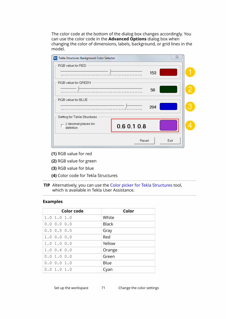
The color code at the bottom of the dialog box changes accordingly. Youcan use the color code in the Advanced Options dialog box whenchanging the color of dimensions, labels, background, or grid lines in themodel.
(1) RGB value for red
(2) RGB value for green
(3) RGB value for blue
(4) Color code for Tekla Structures
TIP Alternatively, you can use the Color picker for Tekla Structures tool,which is available in Tekla User Assistance.
Examples
Color code Color1.0 1.0 1.0 White0.0 0.0 0.0 Black0.5 0.5 0.5 Gray1.0 0.0 0.0 Red1.0 1.0 0.0 Yellow1.0 0.6 0.0 Orange0.0 1.0 0.0 Green0.0 0.0 1.0 Blue0.0 1.0 1.0 Cyan
Set up the workspace 71 Change the color settings
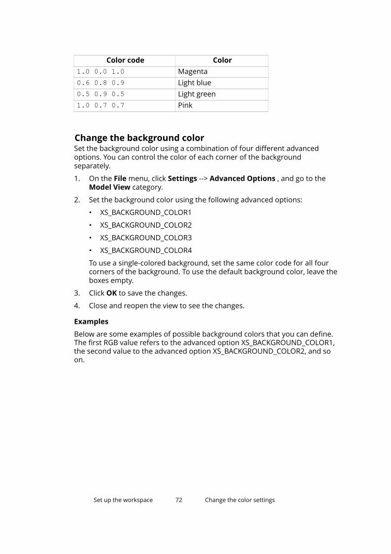
Color code Color1.0 0.0 1.0 Magenta0.6 0.8 0.9 Light blue0.5 0.9 0.5 Light green1.0 0.7 0.7 Pink
Change the background colorSet the background color using a combination of four different advancedoptions. You can control the color of each corner of the backgroundseparately.
1. On the File menu, click Settings --> Advanced Options , and go to theModel View category.
2. Set the background color using the following advanced options:
• XS_BACKGROUND_COLOR1
• XS_BACKGROUND_COLOR2
• XS_BACKGROUND_COLOR3
• XS_BACKGROUND_COLOR4
To use a single-colored background, set the same color code for all fourcorners of the background. To use the default background color, leave theboxes empty.
3. Click OK to save the changes.
4. Close and reopen the view to see the changes.
Examples
Below are some examples of possible background colors that you can define.The first RGB value refers to the advanced option XS_BACKGROUND_COLOR1,the second value to the advanced option XS_BACKGROUND_COLOR2, and soon.
Set up the workspace 72 Change the color settings
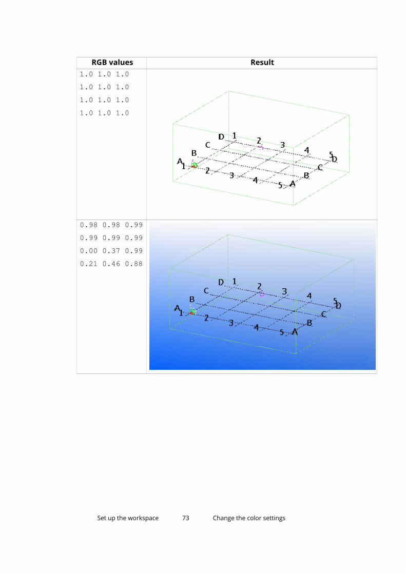
RGB values Result1.0 1.0 1.01.0 1.0 1.01.0 1.0 1.01.0 1.0 1.0
0.98 0.98 0.990.99 0.99 0.990.00 0.37 0.990.21 0.46 0.88
Set up the workspace 73 Change the color settings
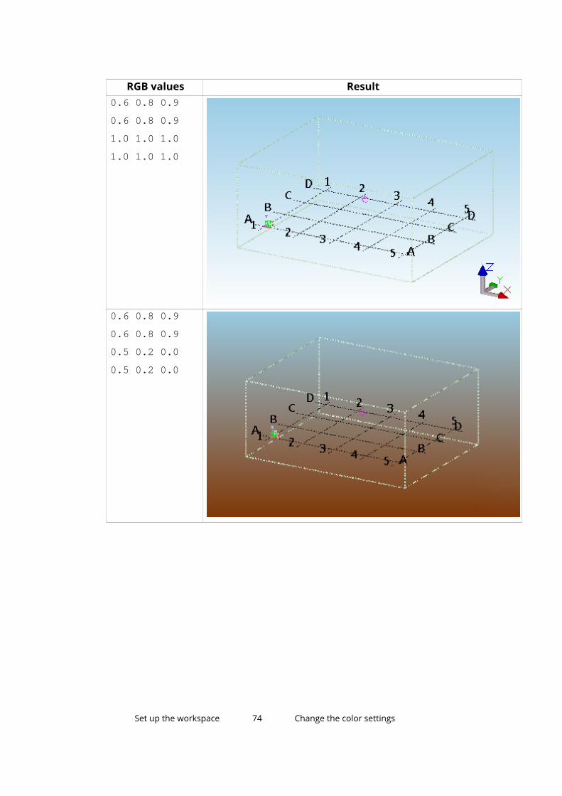
RGB values Result0.6 0.8 0.90.6 0.8 0.91.0 1.0 1.01.0 1.0 1.0
0.6 0.8 0.90.6 0.8 0.90.5 0.2 0.00.5 0.2 0.0
Set up the workspace 74 Change the color settings
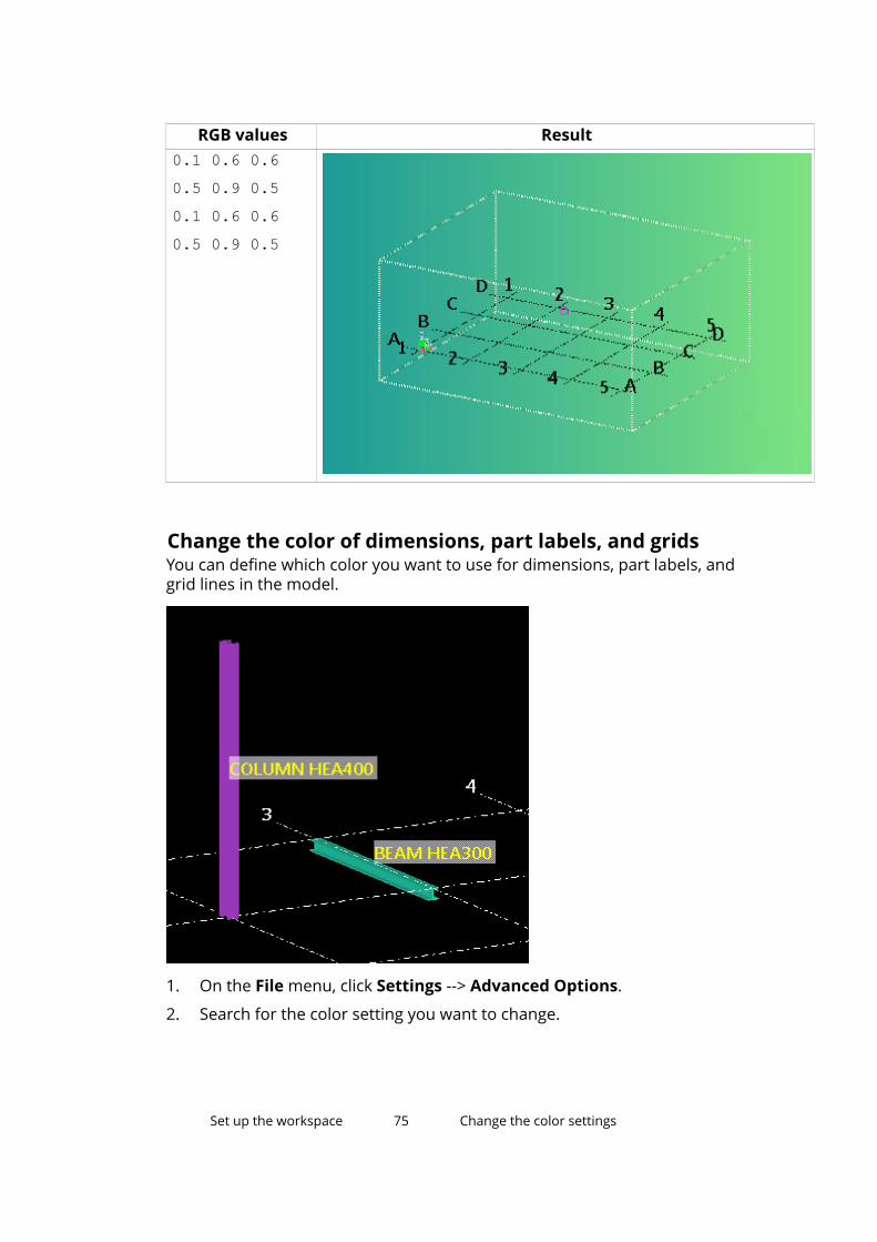
RGB values Result0.1 0.6 0.60.5 0.9 0.50.1 0.6 0.60.5 0.9 0.5
Change the color of dimensions, part labels, and gridsYou can define which color you want to use for dimensions, part labels, andgrid lines in the model.
1. On the File menu, click Settings --> Advanced Options.
2. Search for the color setting you want to change.
Set up the workspace 75 Change the color settings
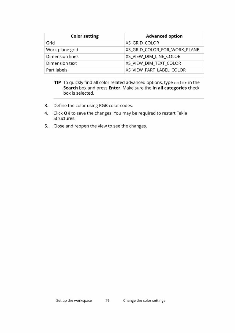
Color setting Advanced optionGrid XS_GRID_COLORWork plane grid XS_GRID_COLOR_FOR_WORK_PLANEDimension lines XS_VIEW_DIM_LINE_COLORDimension text XS_VIEW_DIM_TEXT_COLORPart labels XS_VIEW_PART_LABEL_COLOR
TIP To quickly find all color related advanced options, type color in theSearch box and press Enter. Make sure the In all categories checkbox is selected.
3. Define the color using RGB color codes.
4. Click OK to save the changes. You may be required to restart TeklaStructures.
5. Close and reopen the view to see the changes.
Set up the workspace 76 Change the color settings
5 Create, modify, and deleteobjects
There are several ways to create, modify, and delete objects in TeklaStructures. Here we will introduce the ways that are most useful for a first-timeuser.
5.1 Create an object1. Run a command that creates an object.
For example, click to create a steel beam.
2. Pick points (page 91) to place the object in the model.
Tekla Structures creates the object using the current properties of theobject type.
3. Follow the status bar messages (page 32) to get instructions on how toproceed.
4. To create more objects with the same properties, pick more points.
The command runs until you end it or start another command (page 26).
5. To delete an object, select it and press Delete.
5.2 Modify object properties in a dialog boxUse this method when modifying object properties in a traditional dialog box.This method is used for most parts, for example.
1. Double-click an object to modify it.
Create, modify, and delete objects 77 Create an object
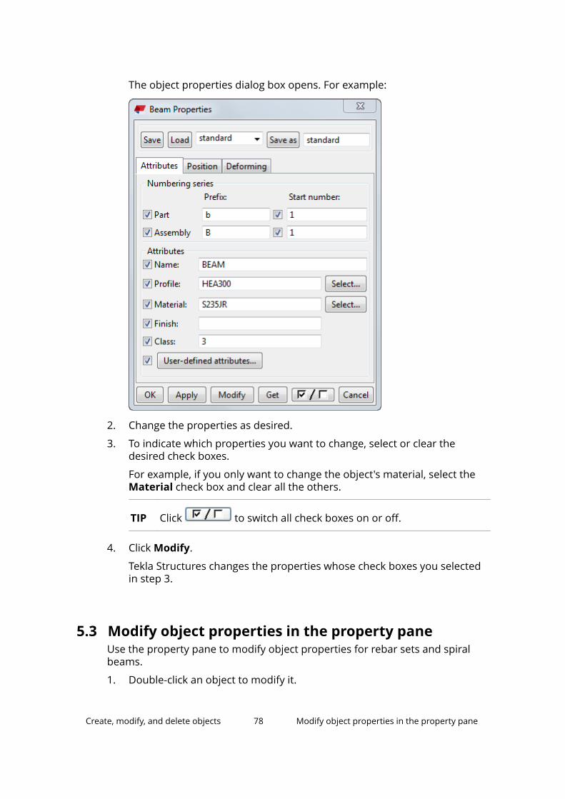
The object properties dialog box opens. For example:
2. Change the properties as desired.
3. To indicate which properties you want to change, select or clear thedesired check boxes.
For example, if you only want to change the object's material, select theMaterial check box and clear all the others.
TIP Click to switch all check boxes on or off.
4. Click Modify.
Tekla Structures changes the properties whose check boxes you selectedin step 3.
5.3 Modify object properties in the property paneUse the property pane to modify object properties for rebar sets and spiralbeams.
1. Double-click an object to modify it.
Create, modify, and delete objects 78 Modify object properties in the property pane
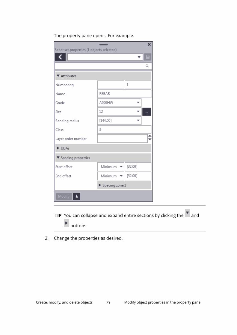
The property pane opens. For example:
TIP You can collapse and expand entire sections by clicking the and
buttons.
2. Change the properties as desired.
Create, modify, and delete objects 79 Modify object properties in the property pane
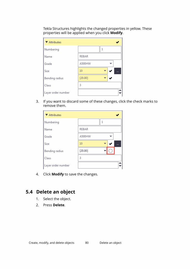
Tekla Structures highlights the changed properties in yellow. Theseproperties will be applied when you click Modify.
3. If you want to discard some of these changes, click the check marks toremove them.
4. Click Modify to save the changes.
5.4 Delete an object1. Select the object.
2. Press Delete.
Create, modify, and delete objects 80 Delete an object
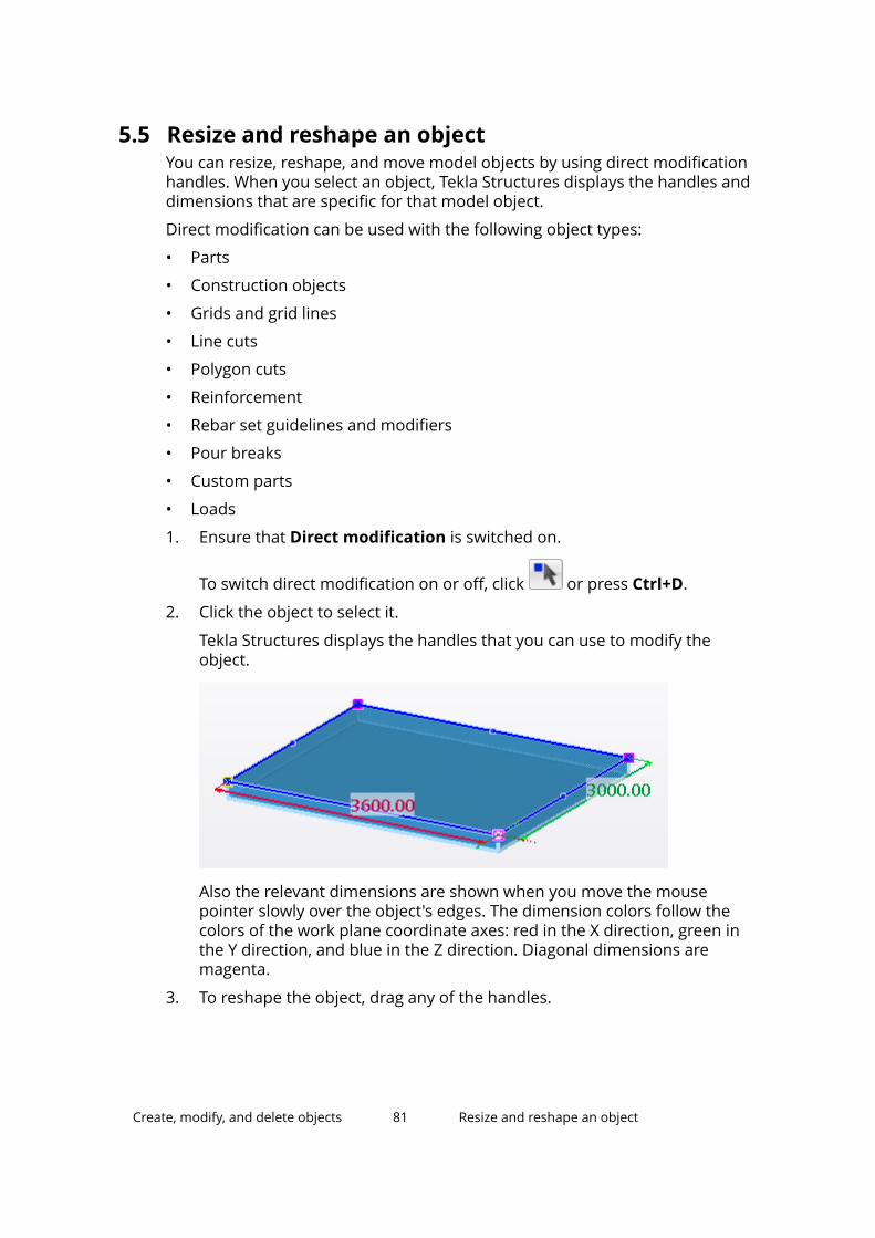
5.5 Resize and reshape an objectYou can resize, reshape, and move model objects by using direct modificationhandles. When you select an object, Tekla Structures displays the handles anddimensions that are specific for that model object.
Direct modification can be used with the following object types:
• Parts
• Construction objects
• Grids and grid lines
• Line cuts
• Polygon cuts
• Reinforcement
• Rebar set guidelines and modifiers
• Pour breaks
• Custom parts
• Loads
1. Ensure that Direct modification is switched on.
To switch direct modification on or off, click or press Ctrl+D.
2. Click the object to select it.
Tekla Structures displays the handles that you can use to modify theobject.
Also the relevant dimensions are shown when you move the mousepointer slowly over the object's edges. The dimension colors follow thecolors of the work plane coordinate axes: red in the X direction, green inthe Y direction, and blue in the Z direction. Diagonal dimensions aremagenta.
3. To reshape the object, drag any of the handles.
Create, modify, and delete objects 81 Resize and reshape an object
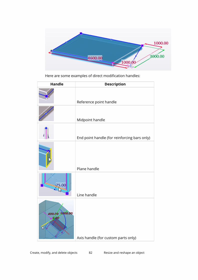
Here are some examples of direct modification handles:
Handle Description
Reference point handle
Midpoint handle
End point handle (for reinforcing bars only)
Plane handle
Line handle
Axis handle (for custom parts only)
Create, modify, and delete objects 82 Resize and reshape an object
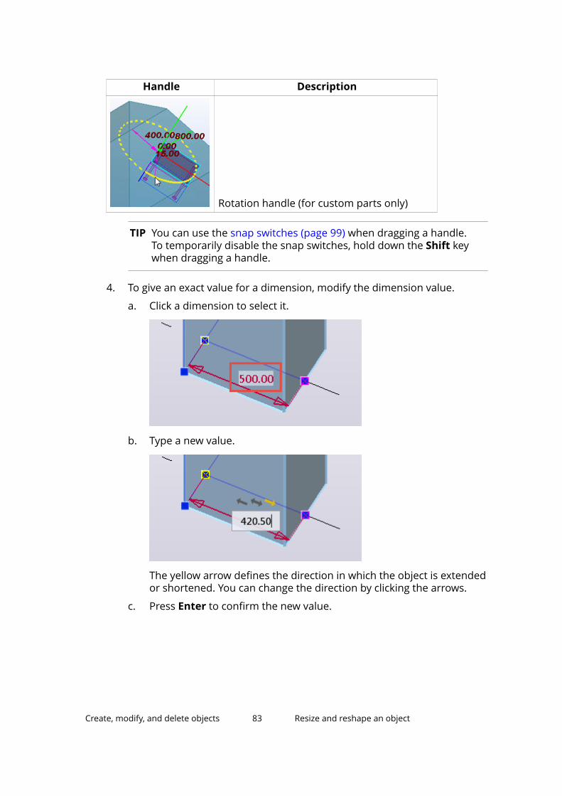
Handle Description
Rotation handle (for custom parts only)
TIP You can use the snap switches (page 99) when dragging a handle.To temporarily disable the snap switches, hold down the Shift keywhen dragging a handle.
4. To give an exact value for a dimension, modify the dimension value.
a. Click a dimension to select it.
b. Type a new value.
The yellow arrow defines the direction in which the object is extendedor shortened. You can change the direction by clicking the arrows.
c. Press Enter to confirm the new value.
Create, modify, and delete objects 83 Resize and reshape an object
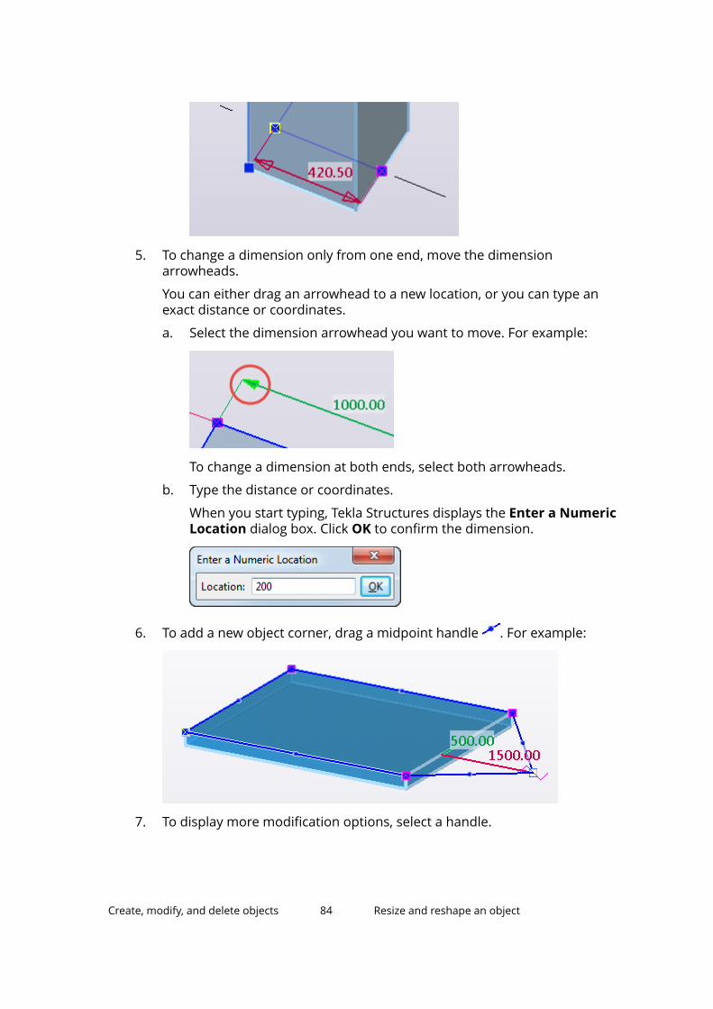
5. To change a dimension only from one end, move the dimensionarrowheads.
You can either drag an arrowhead to a new location, or you can type anexact distance or coordinates.
a. Select the dimension arrowhead you want to move. For example:
To change a dimension at both ends, select both arrowheads.
b. Type the distance or coordinates.
When you start typing, Tekla Structures displays the Enter a NumericLocation dialog box. Click OK to confirm the dimension.
6. To add a new object corner, drag a midpoint handle . For example:
7. To display more modification options, select a handle.
Create, modify, and delete objects 84 Resize and reshape an object
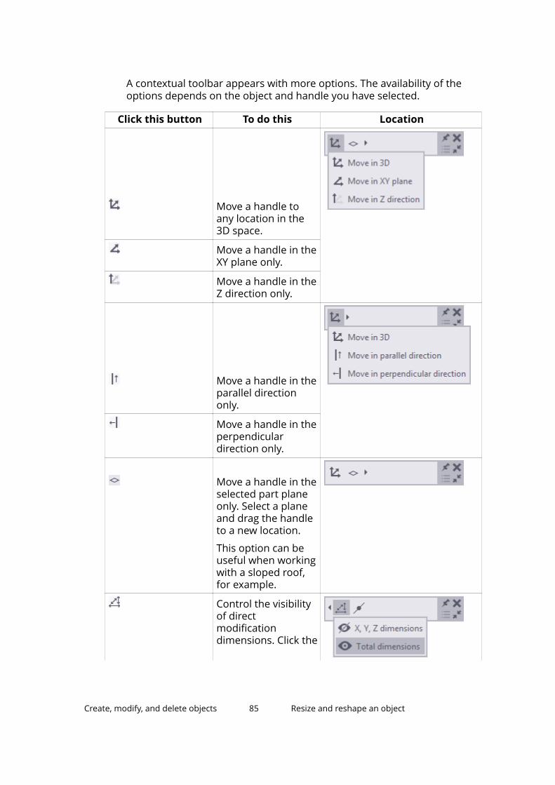
A contextual toolbar appears with more options. The availability of theoptions depends on the object and handle you have selected.
Click this button To do this Location
Move a handle toany location in the3D space.
Move a handle in theXY plane only.
Move a handle in theZ direction only.
Move a handle in theparallel directiononly.
Move a handle in theperpendiculardirection only.
Move a handle in theselected part planeonly. Select a planeand drag the handleto a new location.
This option can beuseful when workingwith a sloped roof,for example.
Control the visibilityof directmodificationdimensions. Click the
Create, modify, and delete objects 85 Resize and reshape an object
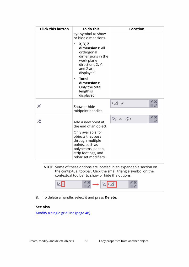
Click this button To do this Locationeye symbol to showor hide dimensions.
• X, Y, Zdimensions: Allorthogonaldimensions in thework planedirections X, Y,and Z aredisplayed.
• Totaldimensions:Only the totallength isdisplayed.
Show or hidemidpoint handles.
Add a new point atthe end of an object.
Only available forobjects that passthrough multiplepoints, such aspolybeams, panels,strip footings, andrebar set modifiers.
NOTE Some of these options are located in an expandable section onthe contextual toolbar. Click the small triangle symbol on thecontextual toolbar to show or hide the options:
8. To delete a handle, select it and press Delete.
See also
Modify a single grid line (page 48)
Create, modify, and delete objects 86 Copy properties from another object
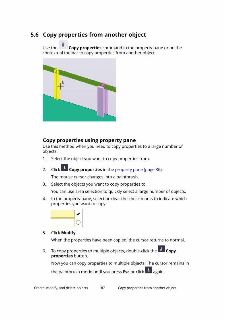
5.6 Copy properties from another object
Use the Copy properties command in the property pane or on thecontextual toolbar to copy properties from another object.
Copy properties using property paneUse this method when you need to copy properties to a large number ofobjects.
1. Select the object you want to copy properties from.
2. Click Copy properties in the property pane (page 36).
The mouse cursor changes into a paintbrush.
3. Select the objects you want to copy properties to.
You can use area selection to quickly select a large number of objects.
4. In the property pane, select or clear the check marks to indicate whichproperties you want to copy.
5. Click Modify.
When the properties have been copied, the cursor returns to normal.
6. To copy properties to multiple objects, double-click the Copyproperties button.
Now you can copy properties to multiple objects. The cursor remains in
the paintbrush mode until you press Esc or click again.
Create, modify, and delete objects 87 Copy properties from another object
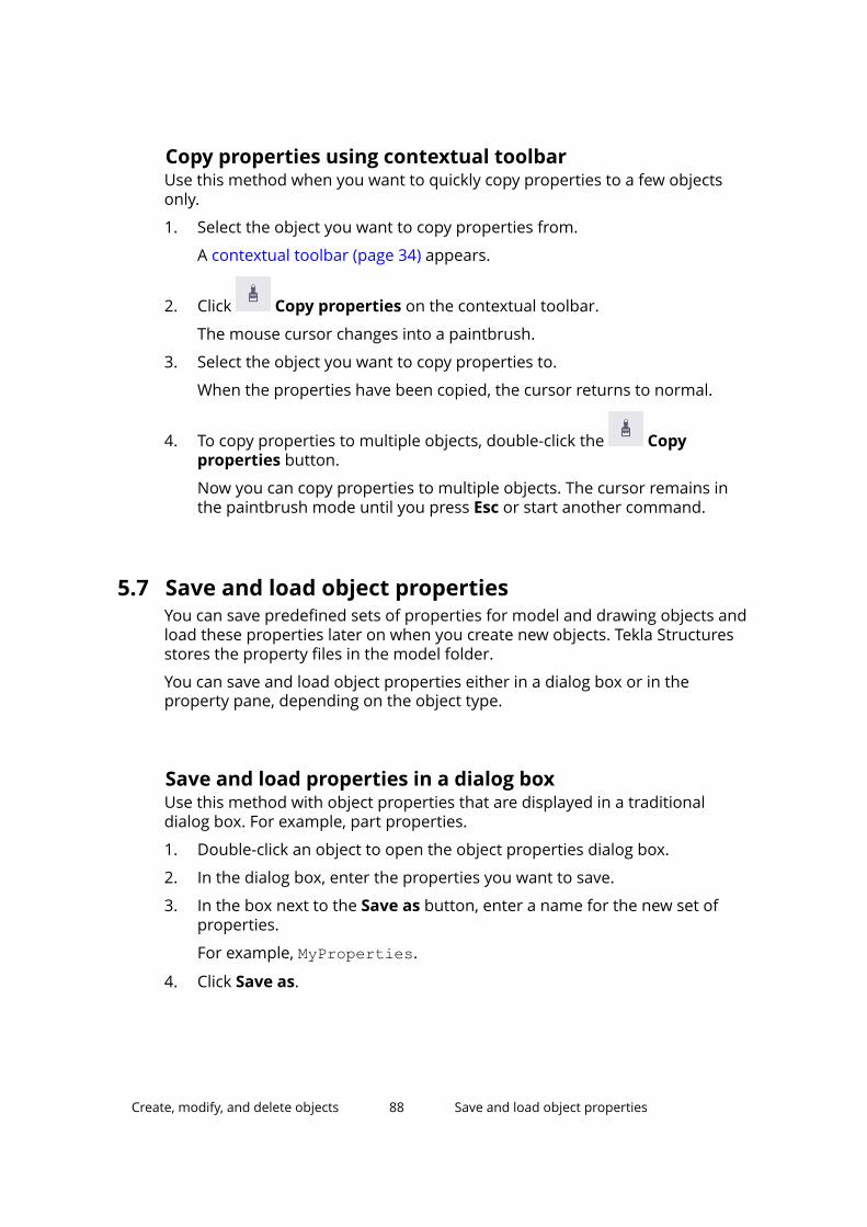
Copy properties using contextual toolbarUse this method when you want to quickly copy properties to a few objectsonly.
1. Select the object you want to copy properties from.
A contextual toolbar (page 34) appears.
2. Click Copy properties on the contextual toolbar.
The mouse cursor changes into a paintbrush.
3. Select the object you want to copy properties to.
When the properties have been copied, the cursor returns to normal.
4. To copy properties to multiple objects, double-click the Copyproperties button.
Now you can copy properties to multiple objects. The cursor remains inthe paintbrush mode until you press Esc or start another command.
5.7 Save and load object propertiesYou can save predefined sets of properties for model and drawing objects andload these properties later on when you create new objects. Tekla Structuresstores the property files in the model folder.
You can save and load object properties either in a dialog box or in theproperty pane, depending on the object type.
Save and load properties in a dialog boxUse this method with object properties that are displayed in a traditionaldialog box. For example, part properties.
1. Double-click an object to open the object properties dialog box.
2. In the dialog box, enter the properties you want to save.
3. In the box next to the Save as button, enter a name for the new set ofproperties.
For example, MyProperties.
4. Click Save as.
Create, modify, and delete objects 88 Save and load object properties
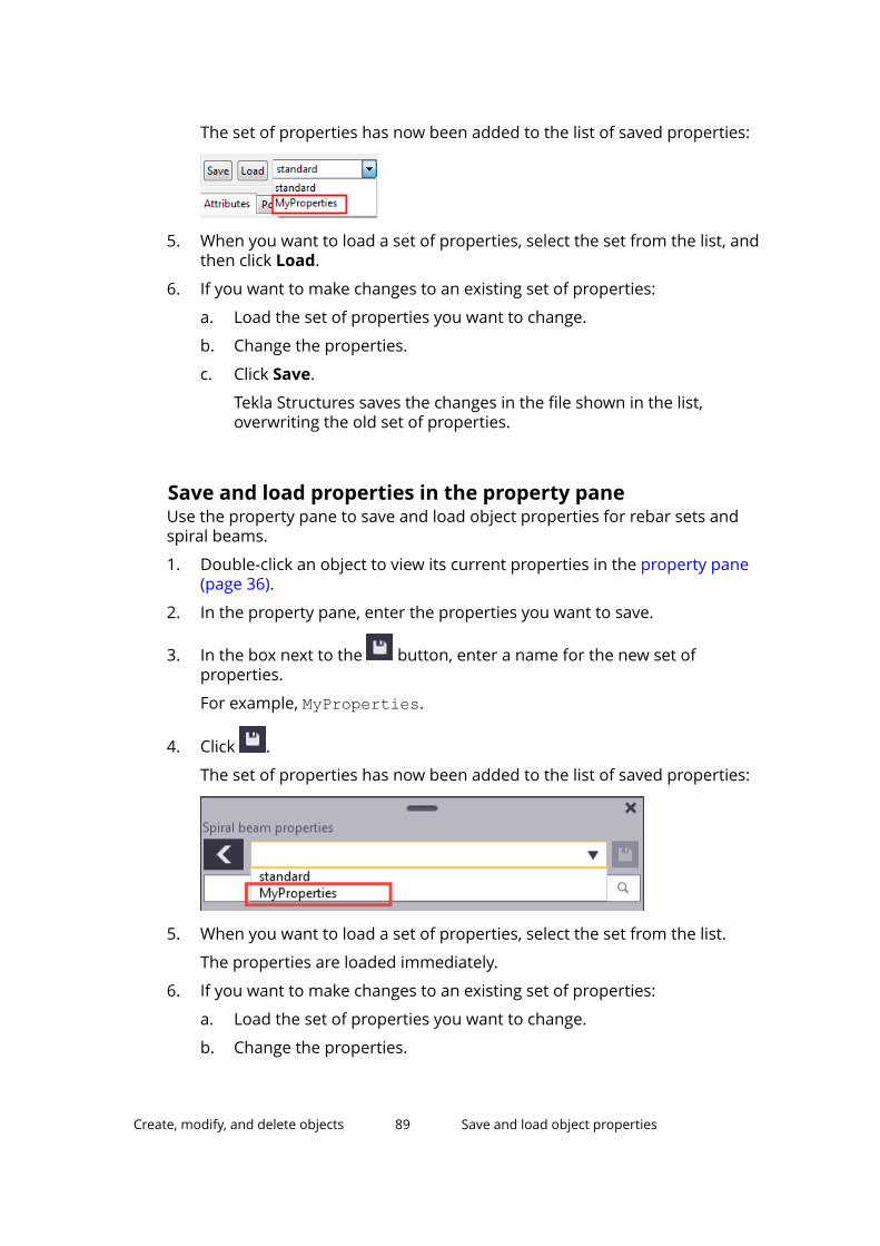
The set of properties has now been added to the list of saved properties:
5. When you want to load a set of properties, select the set from the list, andthen click Load.
6. If you want to make changes to an existing set of properties:
a. Load the set of properties you want to change.
b. Change the properties.
c. Click Save.
Tekla Structures saves the changes in the file shown in the list,overwriting the old set of properties.
Save and load properties in the property paneUse the property pane to save and load object properties for rebar sets andspiral beams.
1. Double-click an object to view its current properties in the property pane(page 36).
2. In the property pane, enter the properties you want to save.
3. In the box next to the button, enter a name for the new set ofproperties.
For example, MyProperties.
4. Click .
The set of properties has now been added to the list of saved properties:
5. When you want to load a set of properties, select the set from the list.
The properties are loaded immediately.
6. If you want to make changes to an existing set of properties:
a. Load the set of properties you want to change.
b. Change the properties.
Create, modify, and delete objects 89 Save and load object properties
c. Click .
Tekla Structures saves the changes in the file shown in the list,overwriting the old set of properties.
Remove existing propertiesYou can remove user-defined property sets manually by removing them fromthe model's \attributes folder. Predefined object properties cannot beremoved.
1. Remove the desired property file from the model's \attributes folder.
The property files may have different file name extensions, depending ontheir type. For more information, see Model folder files and file nameextensions.
2. Restart Tekla Structures.
Create, modify, and delete objects 90 Save and load object properties
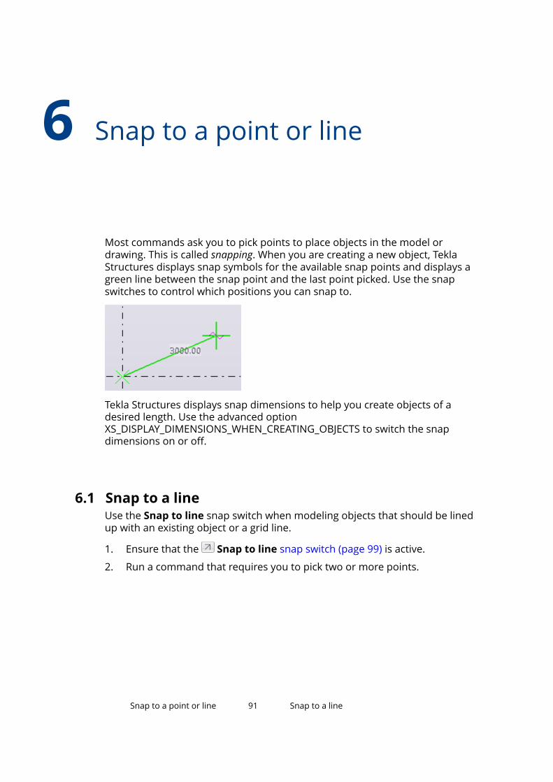
6 Snap to a point or line
Most commands ask you to pick points to place objects in the model ordrawing. This is called snapping. When you are creating a new object, TeklaStructures displays snap symbols for the available snap points and displays agreen line between the snap point and the last point picked. Use the snapswitches to control which positions you can snap to.
Tekla Structures displays snap dimensions to help you create objects of adesired length. Use the advanced optionXS_DISPLAY_DIMENSIONS_WHEN_CREATING_OBJECTS to switch the snapdimensions on or off.
6.1 Snap to a lineUse the Snap to line snap switch when modeling objects that should be linedup with an existing object or a grid line.
1. Ensure that the Snap to line snap switch (page 99) is active.
2. Run a command that requires you to pick two or more points.
Snap to a point or line 91 Snap to a line
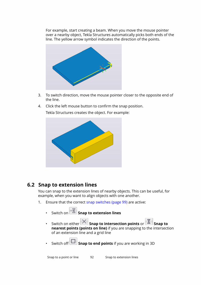
For example, start creating a beam. When you move the mouse pointerover a nearby object, Tekla Structures automatically picks both ends of theline. The yellow arrow symbol indicates the direction of the points.
3. To switch direction, move the mouse pointer closer to the opposite end ofthe line.
4. Click the left mouse button to confirm the snap position.
Tekla Structures creates the object. For example:
6.2 Snap to extension linesYou can snap to the extension lines of nearby objects. This can be useful, forexample, when you want to align objects with one another.
1. Ensure that the correct snap switches (page 99) are active:
• Switch on Snap to extension lines
• Switch on either Snap to intersection points or Snap tonearest points (points on line) if you are snapping to the intersectionof an extension line and a grid line
• Switch off Snap to end points if you are working in 3D
Snap to a point or line 92 Snap to extension lines
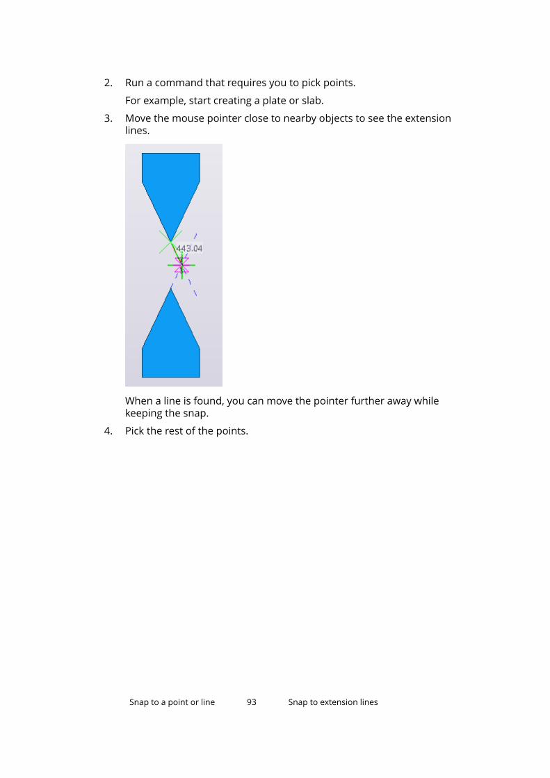
2. Run a command that requires you to pick points.
For example, start creating a plate or slab.
3. Move the mouse pointer close to nearby objects to see the extensionlines.
When a line is found, you can move the pointer further away whilekeeping the snap.
4. Pick the rest of the points.
Snap to a point or line 93 Snap to extension lines
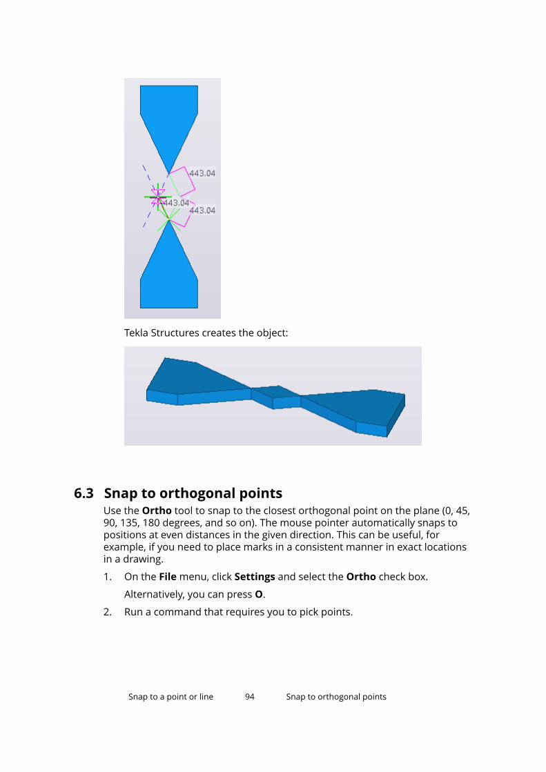
Tekla Structures creates the object:
6.3 Snap to orthogonal pointsUse the Ortho tool to snap to the closest orthogonal point on the plane (0, 45,90, 135, 180 degrees, and so on). The mouse pointer automatically snaps topositions at even distances in the given direction. This can be useful, forexample, if you need to place marks in a consistent manner in exact locationsin a drawing.
1. On the File menu, click Settings and select the Ortho check box.
Alternatively, you can press O.
2. Run a command that requires you to pick points.
Snap to a point or line 94 Snap to orthogonal points
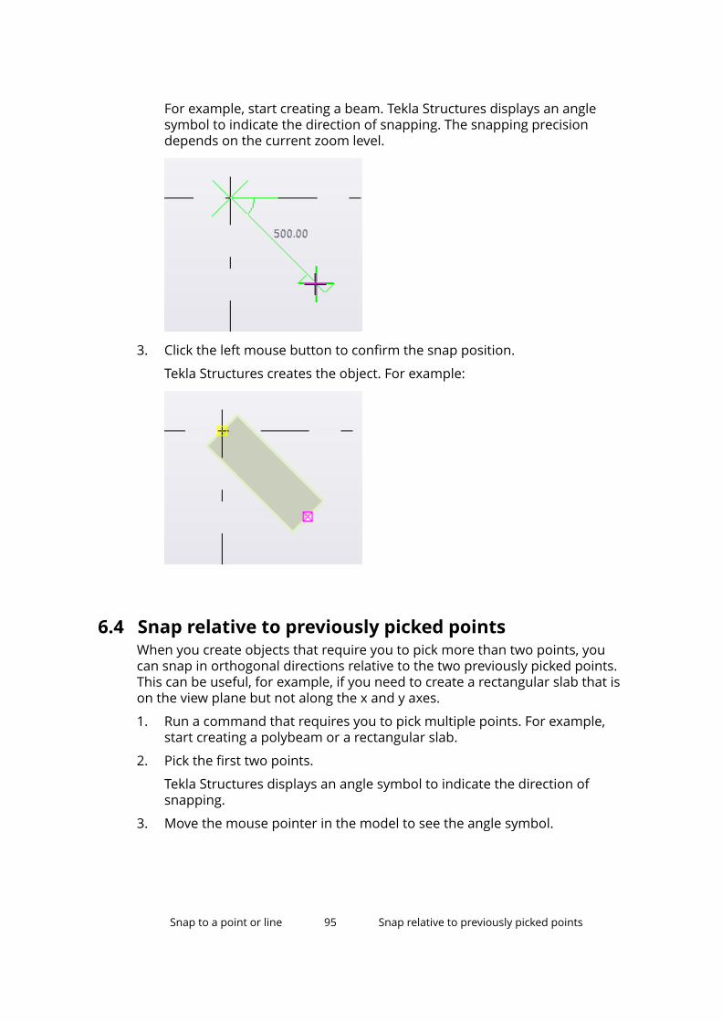
For example, start creating a beam. Tekla Structures displays an anglesymbol to indicate the direction of snapping. The snapping precisiondepends on the current zoom level.
3. Click the left mouse button to confirm the snap position.
Tekla Structures creates the object. For example:
6.4 Snap relative to previously picked pointsWhen you create objects that require you to pick more than two points, youcan snap in orthogonal directions relative to the two previously picked points.This can be useful, for example, if you need to create a rectangular slab that ison the view plane but not along the x and y axes.
1. Run a command that requires you to pick multiple points. For example,start creating a polybeam or a rectangular slab.
2. Pick the first two points.
Tekla Structures displays an angle symbol to indicate the direction ofsnapping.
3. Move the mouse pointer in the model to see the angle symbol.
Snap to a point or line 95 Snap relative to previously picked points
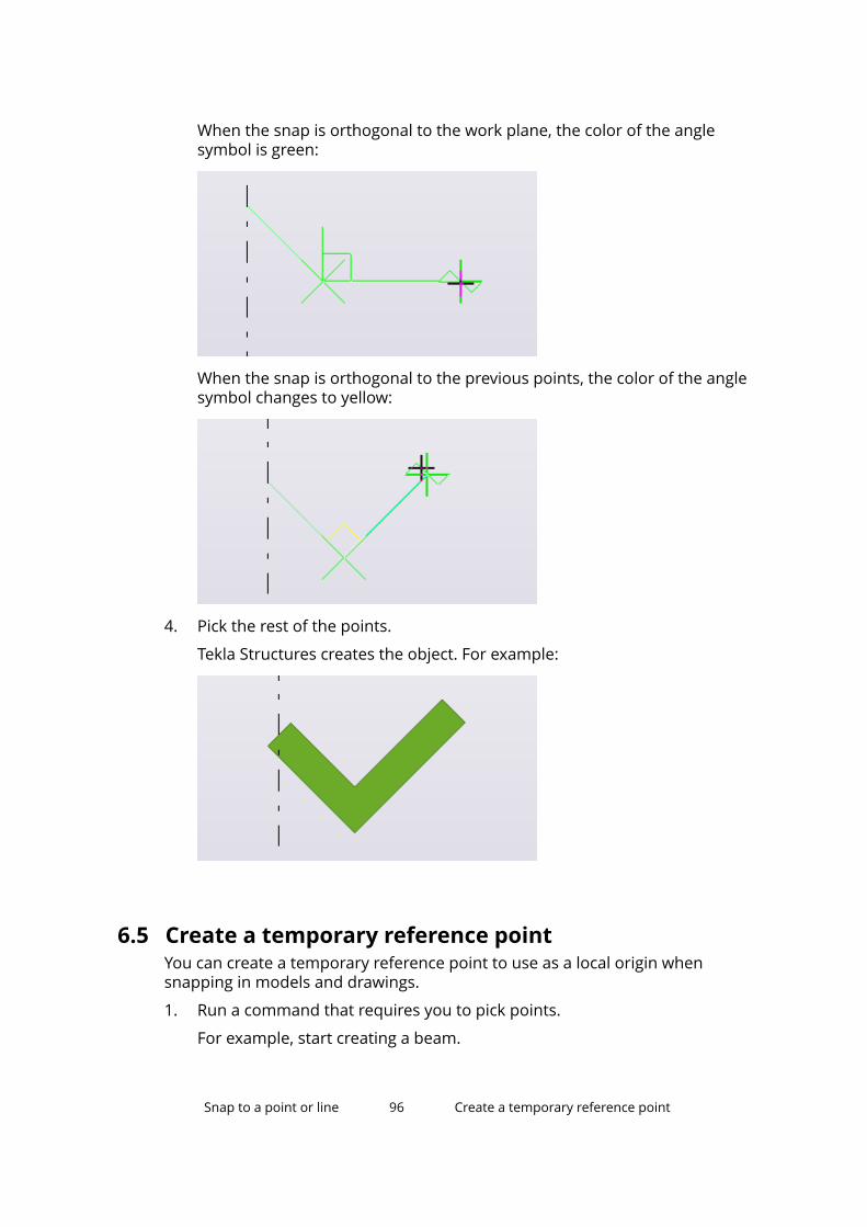
When the snap is orthogonal to the work plane, the color of the anglesymbol is green:
When the snap is orthogonal to the previous points, the color of the anglesymbol changes to yellow:
4. Pick the rest of the points.
Tekla Structures creates the object. For example:
6.5 Create a temporary reference pointYou can create a temporary reference point to use as a local origin whensnapping in models and drawings.
1. Run a command that requires you to pick points.
For example, start creating a beam.
Snap to a point or line 96 Create a temporary reference point
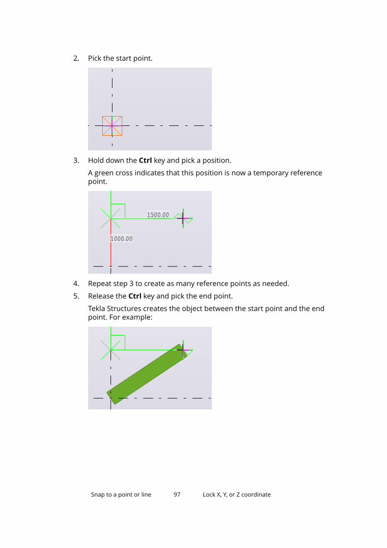
2. Pick the start point.
3. Hold down the Ctrl key and pick a position.
A green cross indicates that this position is now a temporary referencepoint.
4. Repeat step 3 to create as many reference points as needed.
5. Release the Ctrl key and pick the end point.
Tekla Structures creates the object between the start point and the endpoint. For example:
Snap to a point or line 97 Lock X, Y, or Z coordinate
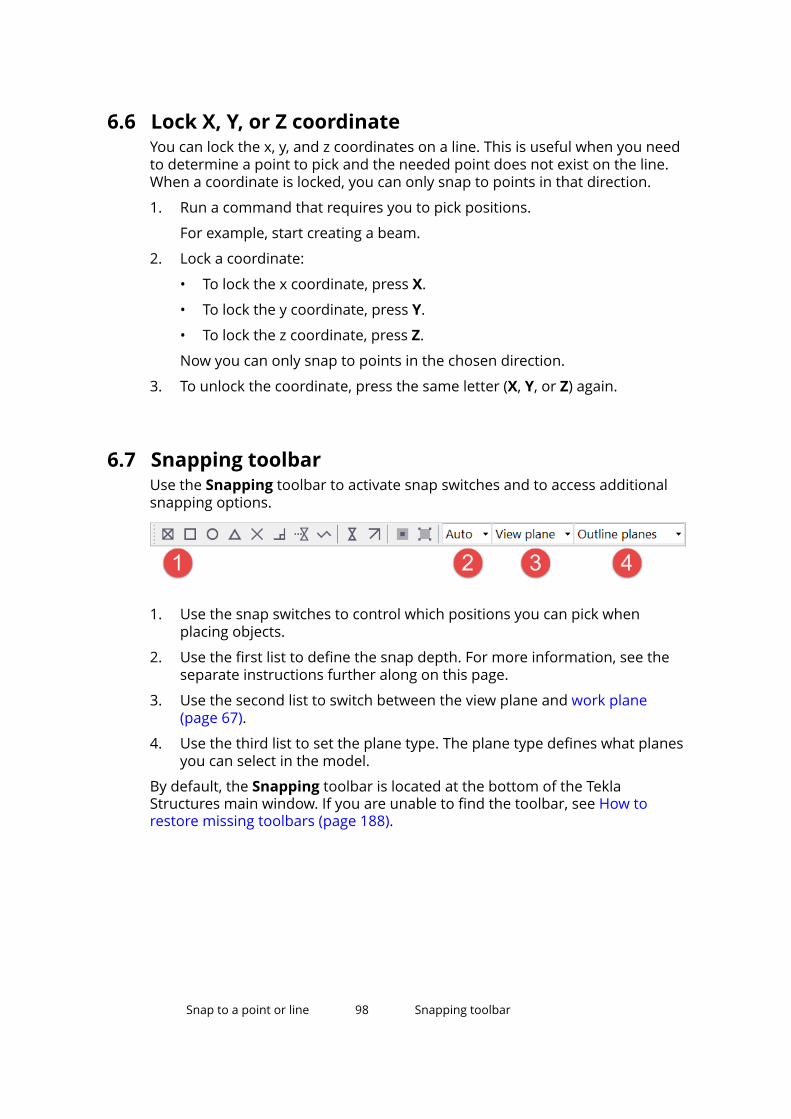
6.6 Lock X, Y, or Z coordinateYou can lock the x, y, and z coordinates on a line. This is useful when you needto determine a point to pick and the needed point does not exist on the line.When a coordinate is locked, you can only snap to points in that direction.
1. Run a command that requires you to pick positions.
For example, start creating a beam.
2. Lock a coordinate:
• To lock the x coordinate, press X.
• To lock the y coordinate, press Y.
• To lock the z coordinate, press Z.
Now you can only snap to points in the chosen direction.
3. To unlock the coordinate, press the same letter (X, Y, or Z) again.
6.7 Snapping toolbarUse the Snapping toolbar to activate snap switches and to access additionalsnapping options.
1. Use the snap switches to control which positions you can pick whenplacing objects.
2. Use the first list to define the snap depth. For more information, see theseparate instructions further along on this page.
3. Use the second list to switch between the view plane and work plane(page 67).
4. Use the third list to set the plane type. The plane type defines what planesyou can select in the model.
By default, the Snapping toolbar is located at the bottom of the TeklaStructures main window. If you are unable to find the toolbar, see How torestore missing toolbars (page 188).
Snap to a point or line 98 Snapping toolbar
Snap zoneEach object has a snap zone. It defines how close you need to pick to hit aposition. When you pick within the snap zone of an object, Tekla Structuresautomatically snaps to the closest pickable point on that object.
You can set the snap zone using the advanced option XS_PIXEL_TOLERANCE.
Snap depthThe first list on the Snapping toolbar defines the depth of each position youpick. You have the following options:
• Plane: You can snap to positions either on the view plane (page 50) or thework plane (page 66), depending on what you have selected in the secondlist on the Snapping toolbar.
• auto: In perspective views, this option works like the 3D option. In non-perspective views, it works like the Plane option.
• 3D: You can snap to positions in the entire 3D space.
Snap priorityTekla Structures automatically snaps to the point with the highest snappriority, but you can also choose another point.
Snapping in drawingsSee Snapping in drawings.
6.8 Snap switches and symbolsUse the snap switches to control which positions you can pick in the model ordrawing. By using snap switches, you can position objects precisely withouthaving to know the coordinates. You can use snap switches whenever TeklaStructures prompts you to pick a point.
Click the snap switches on the Snapping toolbar to switch them on or off. Ifthere is more than one point available to snap to, press the Tab key to cycleforward through the snap points, and Shift+Tab to cycle backwards throughthem. Click the left mouse button to select the appropriate point.
Main snap switches
The two main snap switches define whether you can snap to reference pointsor any other points on objects, for example part corners. These switches have
Snap to a point or line 99 Snap switches and symbols
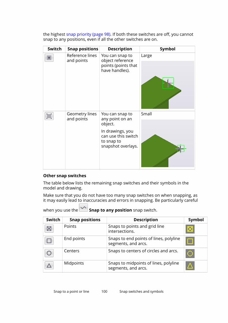
the highest snap priority (page 98). If both these switches are off, you cannotsnap to any positions, even if all the other switches are on.
Switch Snap positions Description SymbolReference linesand points
You can snap toobject referencepoints (points thathave handles).
Large
Geometry linesand points
You can snap toany point on anobject.
In drawings, youcan use this switchto snap tosnapshot overlays.
Small
Other snap switches
The table below lists the remaining snap switches and their symbols in themodel and drawing.
Make sure that you do not have too many snap switches on when snapping, asit may easily lead to inaccuracies and errors in snapping. Be particularly careful
when you use the Snap to any position snap switch.
Switch Snap positions Description SymbolPoints Snaps to points and grid line
intersections.
End points Snaps to end points of lines, polylinesegments, and arcs.
Centers Snaps to centers of circles and arcs.
Midpoints Snaps to midpoints of lines, polylinesegments, and arcs.
Snap to a point or line 100 Snap switches and symbols
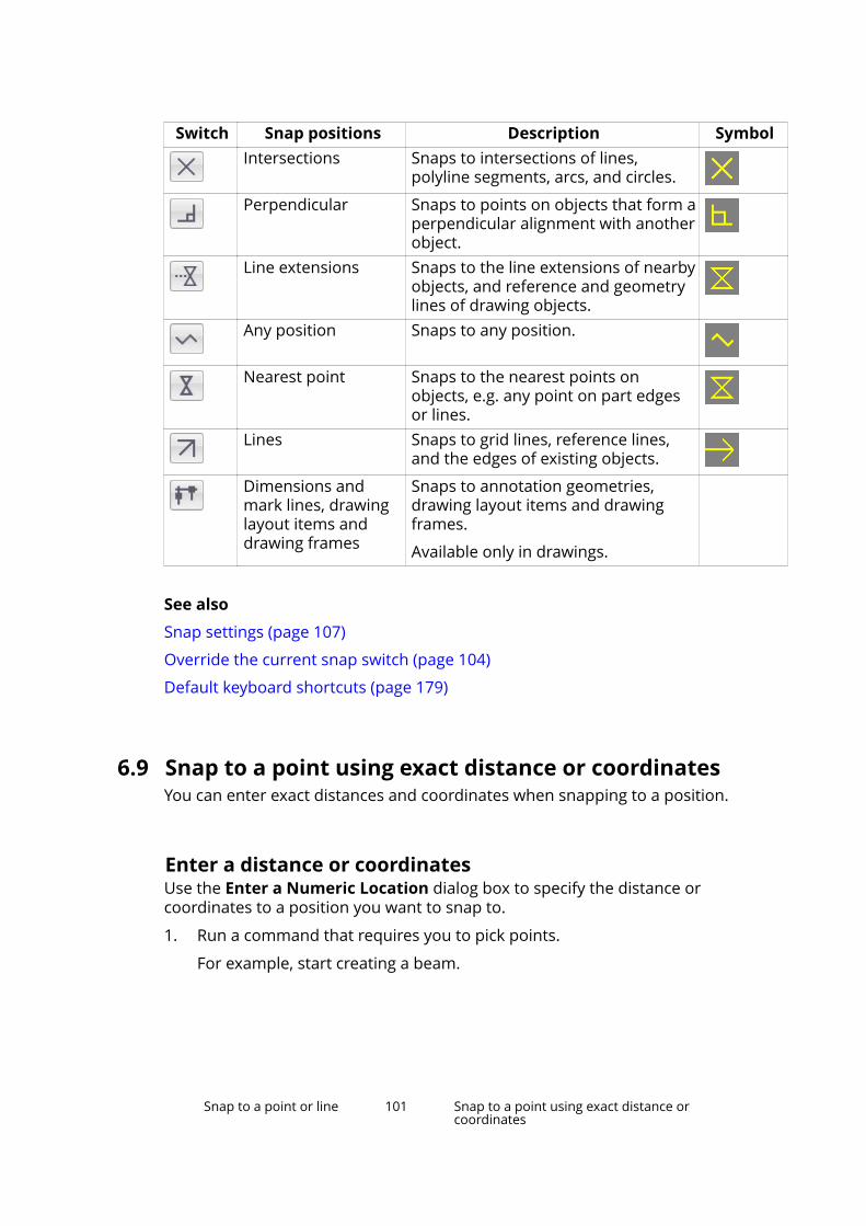
Switch Snap positions Description SymbolIntersections Snaps to intersections of lines,
polyline segments, arcs, and circles.
Perpendicular Snaps to points on objects that form aperpendicular alignment with anotherobject.
Line extensions Snaps to the line extensions of nearbyobjects, and reference and geometrylines of drawing objects.
Any position Snaps to any position.
Nearest point Snaps to the nearest points onobjects, e.g. any point on part edgesor lines.
Lines Snaps to grid lines, reference lines,and the edges of existing objects.
Dimensions andmark lines, drawinglayout items anddrawing frames
Snaps to annotation geometries,drawing layout items and drawingframes.
Available only in drawings.
See also
Snap settings (page 107)
Override the current snap switch (page 104)
Default keyboard shortcuts (page 179)
6.9 Snap to a point using exact distance or coordinatesYou can enter exact distances and coordinates when snapping to a position.
Enter a distance or coordinatesUse the Enter a Numeric Location dialog box to specify the distance orcoordinates to a position you want to snap to.
1. Run a command that requires you to pick points.
For example, start creating a beam.
Snap to a point or line 101 Snap to a point using exact distance orcoordinates
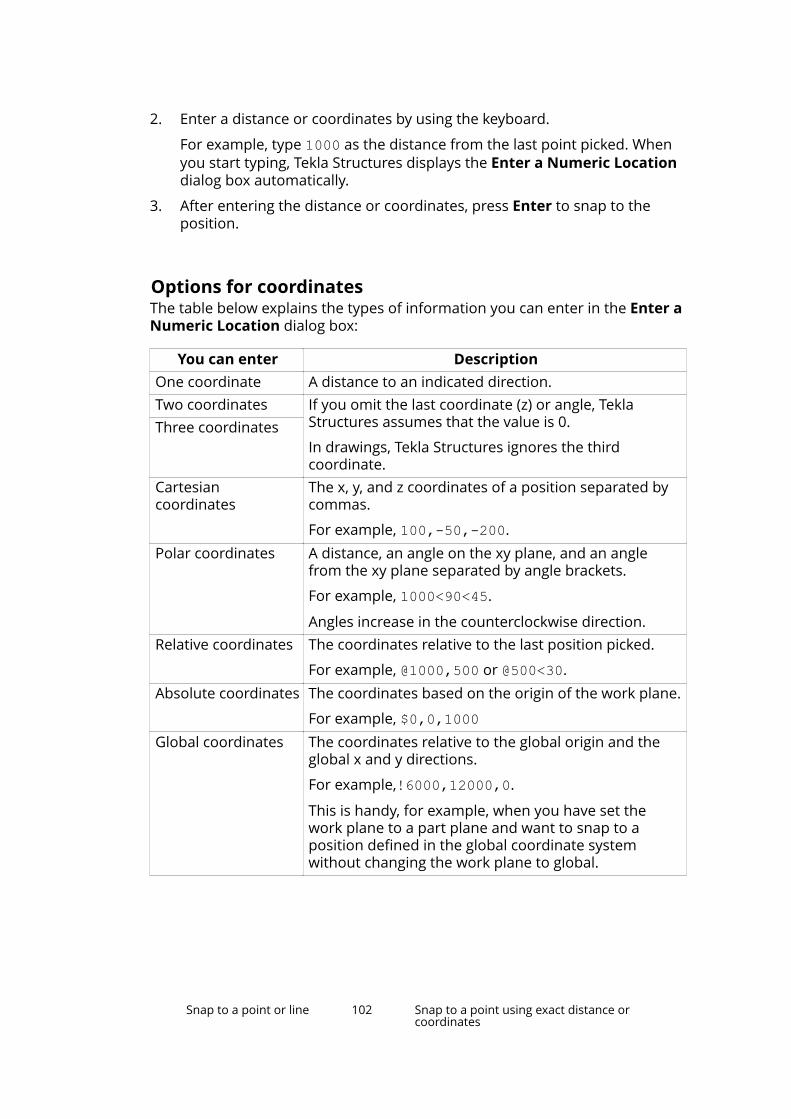
2. Enter a distance or coordinates by using the keyboard.
For example, type 1000 as the distance from the last point picked. Whenyou start typing, Tekla Structures displays the Enter a Numeric Locationdialog box automatically.
3. After entering the distance or coordinates, press Enter to snap to theposition.
Options for coordinatesThe table below explains the types of information you can enter in the Enter aNumeric Location dialog box:
You can enter DescriptionOne coordinate A distance to an indicated direction.Two coordinates If you omit the last coordinate (z) or angle, Tekla
Structures assumes that the value is 0.
In drawings, Tekla Structures ignores the thirdcoordinate.
Three coordinates
Cartesiancoordinates
The x, y, and z coordinates of a position separated bycommas.
For example, 100,-50,-200.Polar coordinates A distance, an angle on the xy plane, and an angle
from the xy plane separated by angle brackets.
For example, 1000<90<45.
Angles increase in the counterclockwise direction.Relative coordinates The coordinates relative to the last position picked.
For example, @1000,500 or @500<30.Absolute coordinates The coordinates based on the origin of the work plane.
For example, $0,0,1000Global coordinates The coordinates relative to the global origin and the
global x and y directions.
For example,!6000,12000,0.
This is handy, for example, when you have set thework plane to a part plane and want to snap to aposition defined in the global coordinate systemwithout changing the work plane to global.
Snap to a point or line 102 Snap to a point using exact distance orcoordinates
Change the snapping modeTekla Structures has three snapping modes: relative, absolute, and global. Usethe advanced option XS_KEYIN_DEFAULT_MODE to indicate the defaultsnapping mode.
1. On the File menu, click Settings --> Advanced Options and go to theModeling Properties category.
2. Set the advanced option XS_KEYIN_DEFAULT_MODE to RELATIVE, ABSOLUTE, or GLOBAL.
This is now the default snapping mode.
3. Click OK to save the changes.
4. If you want to temporarily override the default snapping mode, enter aspecial character in front of the coordinates when entering a numericlocation.
By default, the special characters are:
• @ for relative coordinates
• $ for absolute coordinates
• ! for global coordinates
NOTE If you want to change the special character for any of the threesnapping modes, use the advanced optionsXS_KEYIN_RELATIVE_PREFIX, XS_KEYIN_ABSOLUTE_PREFIX, andXS_KEYIN_GLOBAL_PREFIX.
6.10 Align objects using a snap gridA snap grid makes it easier to align objects in a model, because it allows you tosnap to positions only at set intervals. Use a snap grid when you pick points
using the Snap to any position snap switch.
1. On the File menu, click Settings --> Snap settings.
2. Define the grid spacing intervals in the Spacing boxes.
For example, if the spacing of the x coordinate is 500, you are able to snapto positions at intervals of 500 units in the x direction.
3. If needed, define offsets for the snap grid origin in the Origin boxes.
4. To activate the snap grid, select the Active (when free snap is on) checkbox.
5. Click OK.
Now when you pick points using the
Snap to a point or line 103 Align objects using a snap grid
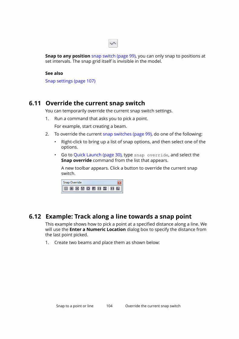
Snap to any position snap switch (page 99), you can only snap to positions atset intervals. The snap grid itself is invisible in the model.
See also
Snap settings (page 107)
6.11 Override the current snap switchYou can temporarily override the current snap switch settings.
1. Run a command that asks you to pick a point.
For example, start creating a beam.
2. To override the current snap switches (page 99), do one of the following:
• Right-click to bring up a list of snap options, and then select one of theoptions.
• Go to Quick Launch (page 30), type snap override, and select theSnap override command from the list that appears.
A new toolbar appears. Click a button to override the current snapswitch.
6.12 Example: Track along a line towards a snap pointThis example shows how to pick a point at a specified distance along a line. Wewill use the Enter a Numeric Location dialog box to specify the distance fromthe last point picked.
1. Create two beams and place them as shown below:
Snap to a point or line 104 Override the current snap switch
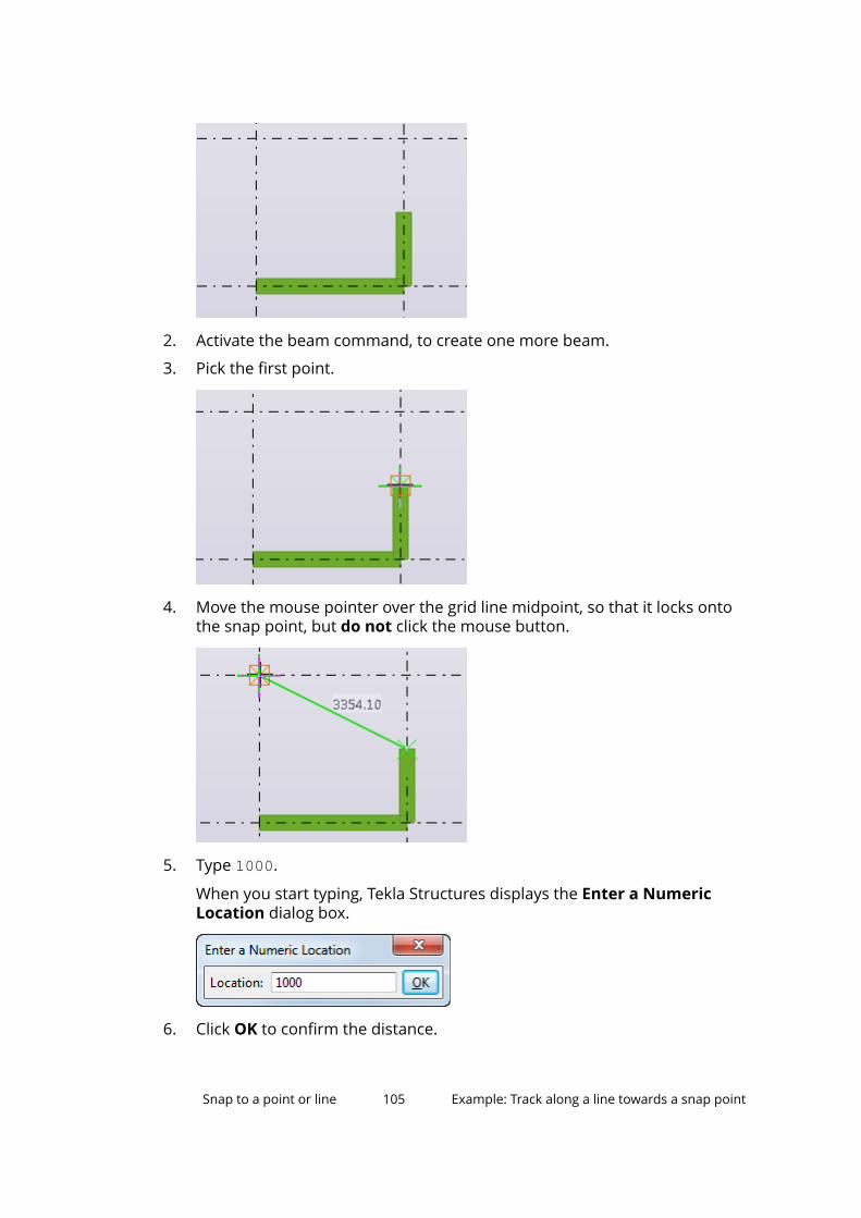
2. Activate the beam command, to create one more beam.
3. Pick the first point.
4. Move the mouse pointer over the grid line midpoint, so that it locks ontothe snap point, but do not click the mouse button.
5. Type 1000.
When you start typing, Tekla Structures displays the Enter a NumericLocation dialog box.
6. Click OK to confirm the distance.
Snap to a point or line 105 Example: Track along a line towards a snap point
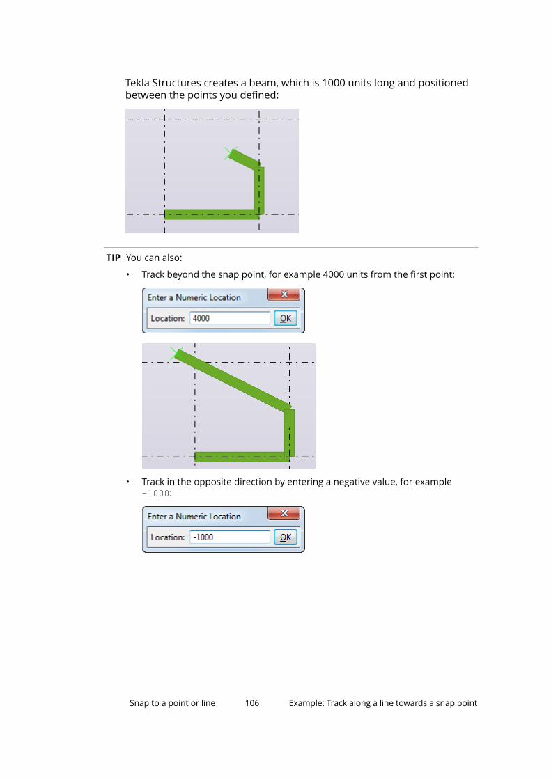
Tekla Structures creates a beam, which is 1000 units long and positionedbetween the points you defined:
TIP You can also:
• Track beyond the snap point, for example 4000 units from the first point:
• Track in the opposite direction by entering a negative value, for example-1000:
Snap to a point or line 106 Example: Track along a line towards a snap point
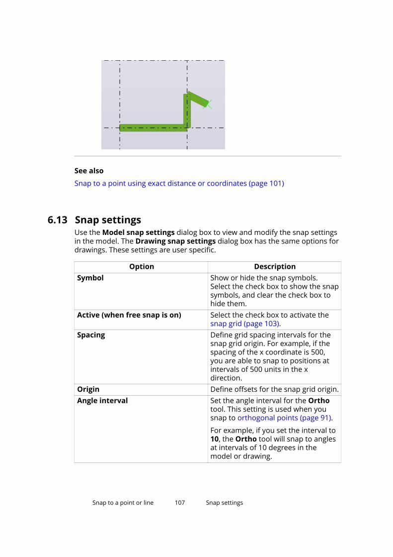
See also
Snap to a point using exact distance or coordinates (page 101)
6.13 Snap settingsUse the Model snap settings dialog box to view and modify the snap settingsin the model. The Drawing snap settings dialog box has the same options fordrawings. These settings are user specific.
Option DescriptionSymbol Show or hide the snap symbols.
Select the check box to show the snapsymbols, and clear the check box tohide them.
Active (when free snap is on) Select the check box to activate thesnap grid (page 103).
Spacing Define grid spacing intervals for thesnap grid origin. For example, if thespacing of the x coordinate is 500,you are able to snap to positions atintervals of 500 units in the xdirection.
Origin Define offsets for the snap grid origin.Angle interval Set the angle interval for the Ortho
tool. This setting is used when yousnap to orthogonal points (page 91).
For example, if you set the interval to10, the Ortho tool will snap to anglesat intervals of 10 degrees in themodel or drawing.
Snap to a point or line 107 Snap settings
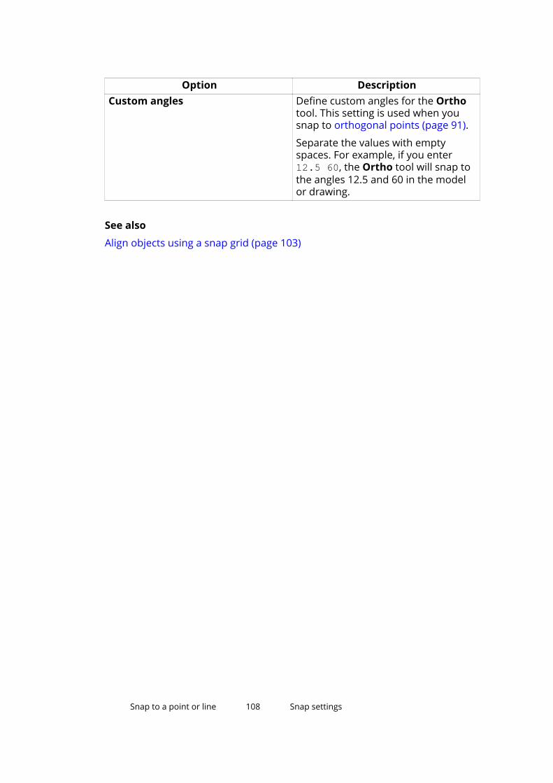
Option DescriptionCustom angles Define custom angles for the Ortho
tool. This setting is used when yousnap to orthogonal points (page 91).
Separate the values with emptyspaces. For example, if you enter12.5 60, the Ortho tool will snap tothe angles 12.5 and 60 in the modelor drawing.
See also
Align objects using a snap grid (page 103)
Snap to a point or line 108 Snap settings
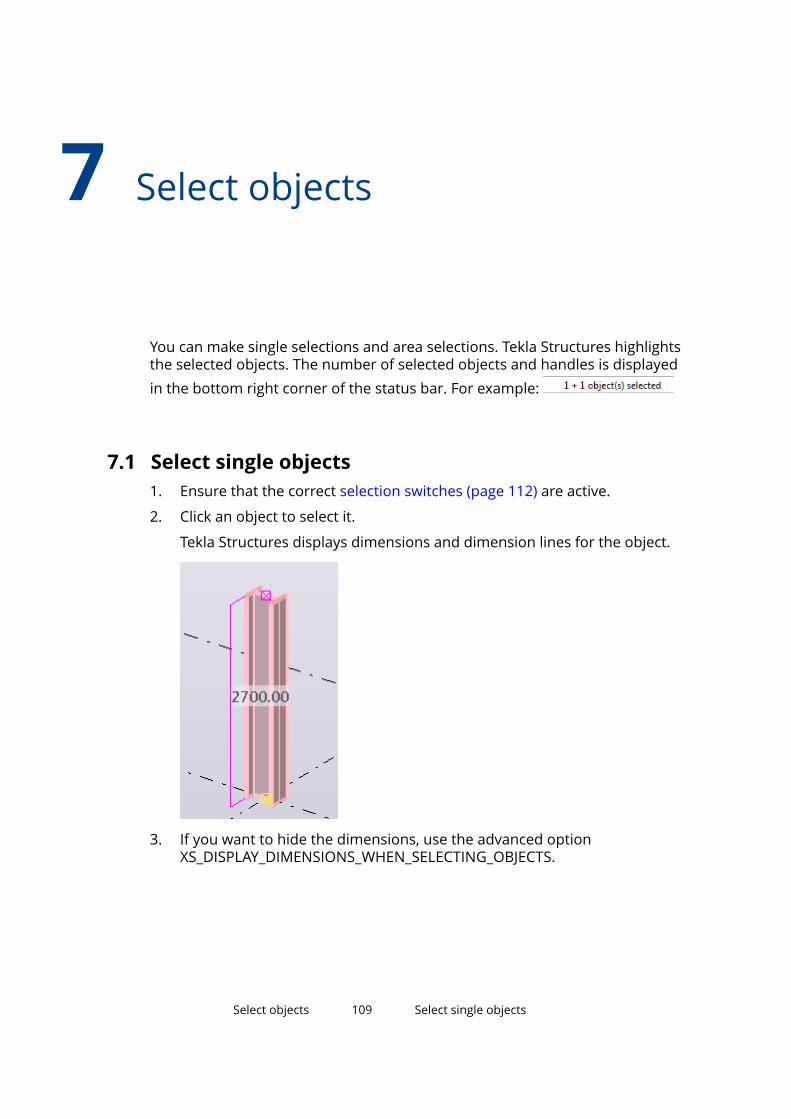
7 Select objects
You can make single selections and area selections. Tekla Structures highlightsthe selected objects. The number of selected objects and handles is displayedin the bottom right corner of the status bar. For example:
7.1 Select single objects1. Ensure that the correct selection switches (page 112) are active.
2. Click an object to select it.
Tekla Structures displays dimensions and dimension lines for the object.
3. If you want to hide the dimensions, use the advanced optionXS_DISPLAY_DIMENSIONS_WHEN_SELECTING_OBJECTS.
Select objects 109 Select single objects
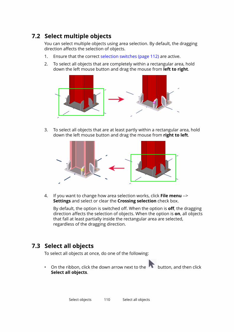
7.2 Select multiple objectsYou can select multiple objects using area selection. By default, the draggingdirection affects the selection of objects.
1. Ensure that the correct selection switches (page 112) are active.
2. To select all objects that are completely within a rectangular area, holddown the left mouse button and drag the mouse from left to right.
3. To select all objects that are at least partly within a rectangular area, holddown the left mouse button and drag the mouse from right to left.
4. If you want to change how area selection works, click File menu -->Settings and select or clear the Crossing selection check box.
By default, the option is switched off. When the option is off, the draggingdirection affects the selection of objects. When the option is on, all objectsthat fall at least partially inside the rectangular area are selected,regardless of the dragging direction.
7.3 Select all objectsTo select all objects at once, do one of the following:
• On the ribbon, click the down arrow next to the button, and then clickSelect all objects.
Select objects 110 Select all objects
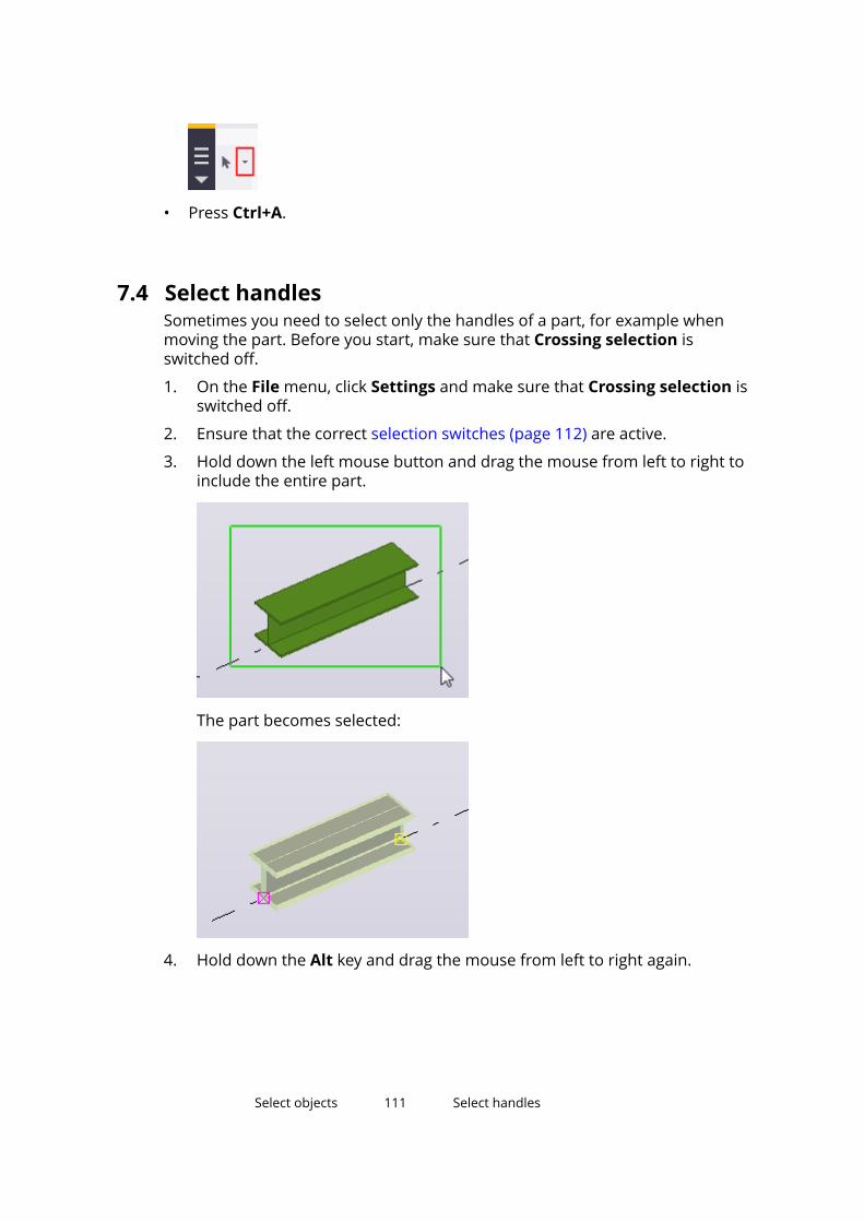
• Press Ctrl+A.
7.4 Select handlesSometimes you need to select only the handles of a part, for example whenmoving the part. Before you start, make sure that Crossing selection isswitched off.
1. On the File menu, click Settings and make sure that Crossing selection isswitched off.
2. Ensure that the correct selection switches (page 112) are active.
3. Hold down the left mouse button and drag the mouse from left to right toinclude the entire part.
The part becomes selected:
4. Hold down the Alt key and drag the mouse from left to right again.
Select objects 111 Select handles
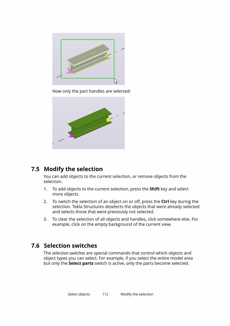
Now only the part handles are selected:
7.5 Modify the selectionYou can add objects to the current selection, or remove objects from theselection.
1. To add objects to the current selection, press the Shift key and selectmore objects.
2. To switch the selection of an object on or off, press the Ctrl key during theselection. Tekla Structures deselects the objects that were already selectedand selects those that were previously not selected.
3. To clear the selection of all objects and handles, click somewhere else. Forexample, click on the empty background of the current view.
7.6 Selection switchesThe selection switches are special commands that control which objects andobject types you can select. For example, if you select the entire model areabut only the Select parts switch is active, only the parts become selected.
Select objects 112 Modify the selection
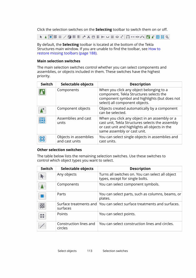
Click the selection switches on the Selecting toolbar to switch them on or off.
By default, the Selecting toolbar is located at the bottom of the TeklaStructures main window. If you are unable to find the toolbar, see How torestore missing toolbars (page 188).
Main selection switches
The main selection switches control whether you can select components andassemblies, or objects included in them. These switches have the highestpriority.
Switch Selectable objects DescriptionComponents When you click any object belonging to a
component, Tekla Structures selects thecomponent symbol and highlights (but does notselect) all component objects.
Component objects Objects created automatically by a componentcan be selected.
Assemblies and castunits
When you click any object in an assembly or acast unit, Tekla Structures selects the assemblyor cast unit and highlights all objects in thesame assembly or cast unit.
Objects in assembliesand cast units
You can select single objects in assemblies andcast units.
Other selection switches
The table below lists the remaining selection switches. Use these switches tocontrol which object types you want to select.
Switch Selectable objects DescriptionAny objects Turns all switches on. You can select all object
types, except for single bolts.Components You can select component symbols.
Parts You can select parts, such as columns, beams, orplates.
Surface treatments andsurfaces
You can select surface treatments and surfaces.
Points You can select points.
Construction lines andcircles
You can select construction lines and circles.
Select objects 113 Selection switches
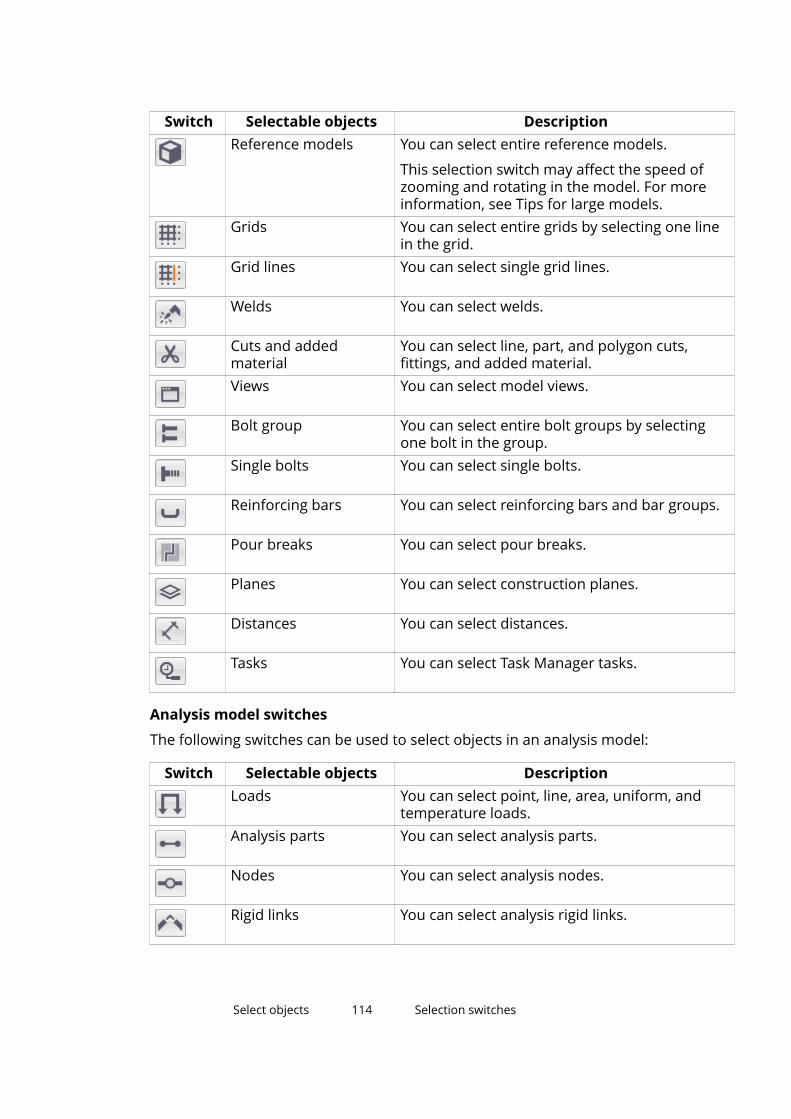
Switch Selectable objects DescriptionReference models You can select entire reference models.
This selection switch may affect the speed ofzooming and rotating in the model. For moreinformation, see Tips for large models.
Grids You can select entire grids by selecting one linein the grid.
Grid lines You can select single grid lines.
Welds You can select welds.
Cuts and addedmaterial
You can select line, part, and polygon cuts,fittings, and added material.
Views You can select model views.
Bolt group You can select entire bolt groups by selectingone bolt in the group.
Single bolts You can select single bolts.
Reinforcing bars You can select reinforcing bars and bar groups.
Pour breaks You can select pour breaks.
Planes You can select construction planes.
Distances You can select distances.
Tasks You can select Task Manager tasks.
Analysis model switches
The following switches can be used to select objects in an analysis model:
Switch Selectable objects DescriptionLoads You can select point, line, area, uniform, and
temperature loads.Analysis parts You can select analysis parts.
Nodes You can select analysis nodes.
Rigid links You can select analysis rigid links.
Select objects 114 Selection switches
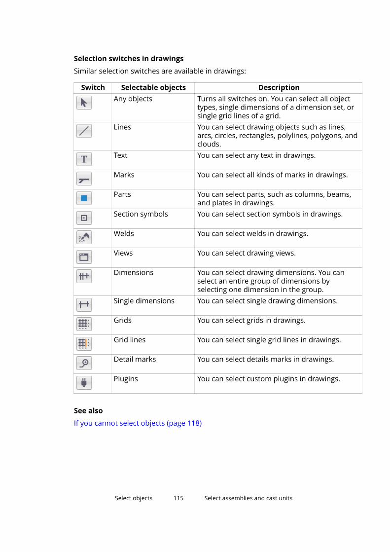
Selection switches in drawings
Similar selection switches are available in drawings:
Switch Selectable objects DescriptionAny objects Turns all switches on. You can select all object
types, single dimensions of a dimension set, orsingle grid lines of a grid.
Lines You can select drawing objects such as lines,arcs, circles, rectangles, polylines, polygons, andclouds.
Text You can select any text in drawings.
Marks You can select all kinds of marks in drawings.
Parts You can select parts, such as columns, beams,and plates in drawings.
Section symbols You can select section symbols in drawings.
Welds You can select welds in drawings.
Views You can select drawing views.
Dimensions You can select drawing dimensions. You canselect an entire group of dimensions byselecting one dimension in the group.
Single dimensions You can select single drawing dimensions.
Grids You can select grids in drawings.
Grid lines You can select single grid lines in drawings.
Detail marks You can select details marks in drawings.
Plugins You can select custom plugins in drawings.
See also
If you cannot select objects (page 118)
Select objects 115 Select assemblies and cast units
7.7 Select assemblies and cast unitsUse the Select assemblies selection switch to select assemblies and castunits.
1. Ensure that the Select assemblies selection switch (page 112) isactive.
2. Select a part.
Tekla Structures selects the entire cast unit or assembly that contains theselected part.
7.8 Select nested objectsYou can select nested assemblies and components. The active selection switchdefines on which level you start and toward which direction you move in thecomponent or assembly hierarchy. The status bar shows the steps you take inthe hierarchy.
1. Ensure that the correct selection switch (page 112) is active.
• : to start from the assemblies on the highest level, move to theirsub-assemblies, and finally select single parts, bolts, and so on
• : to start from single objects and move to bigger and bigger nestedassemblies
• : to start from the components on the highest level, move to theirsub-components, and finally select single parts, bolts, and so on
• : to start from single objects and move to bigger and bigger nestedcomponents
2. Hold down the Shift key.
3. Scroll with the mouse wheel.
Select objects 116 Select nested objects
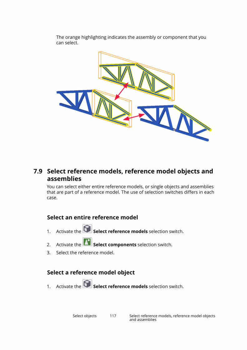
The orange highlighting indicates the assembly or component that youcan select.
7.9 Select reference models, reference model objects andassembliesYou can select either entire reference models, or single objects and assembliesthat are part of a reference model. The use of selection switches differs in eachcase.
Select an entire reference model
1. Activate the Select reference models selection switch.
2. Activate the Select components selection switch.
3. Select the reference model.
Select a reference model object
1. Activate the Select reference models selection switch.
Select objects 117 Select reference models, reference model objectsand assemblies
2. Activate the Select objects in components selection switch.
3. Select the desired object in the reference model.
Select a reference model assembly
1. Activate the Select reference models selection switch.
2. Activate the Select assemblies selection switch.
3. Select the desired assembly in the reference model.
7.10 If you cannot select objectsIf you cannot select desired objects in the model, check the selection switchesand the filter settings.
1. Check that you have switched on all the needed selection switches(page 112).
2. If you still cannot select the objects, check the selection filter settings.
You can select a different filter or modify the current filter.
Select objects 118 If you cannot select objects
8 Copy and move objects
The basic functionality of copying and moving objects is the same in modelsand drawings. You can copy and move objects linearly, with rotation, and withmirroring.
• Copy objects (page 120)
• Move objects (page 132)
• Rotate objects (page 138)
• Mirror objects (page 142)
Duplicate objects
Two objects are considered duplicates if they have the same size andorientation. Tekla Structures checks for duplicate objects when you copy andmove objects or create new parts in the same location as an existing part. Ifduplicates are found, you can choose whether to keep or delete them.
Use the advanced option to define the maximum number of objects that canbe counted as duplicates while copying or moving objects.
NOTE Tekla Structures does not check for duplicates when you copy objectsusing a modeling tool, such as the Array of objects (29) component.
Connected objects
When you copy objects that are connected to another part (such asconnections and bolts), Tekla Structures tries to find suitable new main partsfor these copied objects. If none are found, some of the connected objectsmay not be copied at all. After copying, check that all of the objects have beencopied correctly.
Assemblies and cast units
If you copy or move objects from an assembly or cast unit, Tekla Structurescopies the assembly structure if possible. For example, sub-assemblies arecopied as sub-assemblies if a parent object is found.
Copy and move objects 119 If you cannot select objects
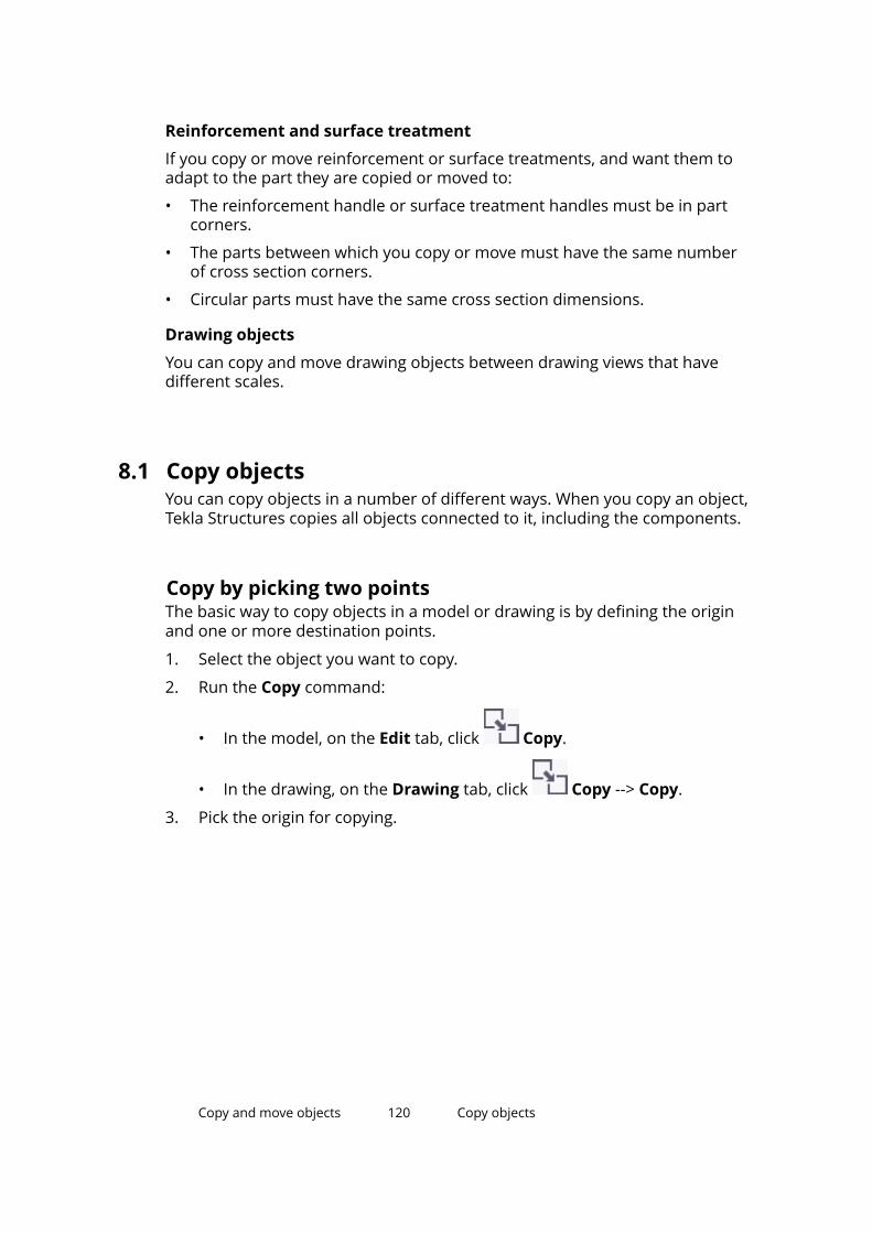
Reinforcement and surface treatment
If you copy or move reinforcement or surface treatments, and want them toadapt to the part they are copied or moved to:
• The reinforcement handle or surface treatment handles must be in partcorners.
• The parts between which you copy or move must have the same numberof cross section corners.
• Circular parts must have the same cross section dimensions.
Drawing objects
You can copy and move drawing objects between drawing views that havedifferent scales.
8.1 Copy objectsYou can copy objects in a number of different ways. When you copy an object,Tekla Structures copies all objects connected to it, including the components.
Copy by picking two pointsThe basic way to copy objects in a model or drawing is by defining the originand one or more destination points.
1. Select the object you want to copy.
2. Run the Copy command:
• In the model, on the Edit tab, click Copy.
• In the drawing, on the Drawing tab, click Copy --> Copy.
3. Pick the origin for copying.
Copy and move objects 120 Copy objects
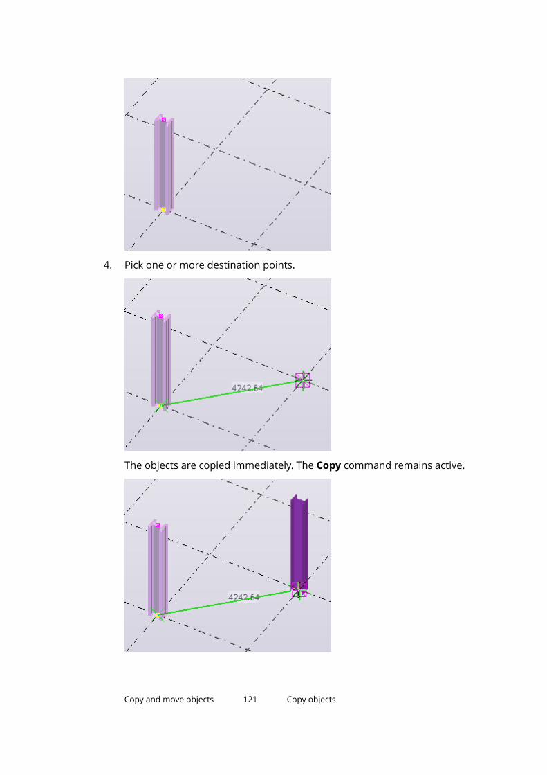
4. Pick one or more destination points.
The objects are copied immediately. The Copy command remains active.
Copy and move objects 121 Copy objects
5. If you want to undo the latest copy operation, click the Undo buttonon the top left corner of the Tekla Structures main window.
The Copy command still remains active.
6. To stop copying, press Esc.
Copy linearlyIn the model, you can create multiple copies of an object in the same lineardirection.
1. Select the objects you want to copy.
2. On the Edit tab, click Copy special --> Linear.
The Copy - Linear dialog box opens.
3. Pick two points, or enter the coordinates in the dx, dy, and dZ boxes.
You can also use a formula to calculate the x, y, and z displacements. Forexample:
4. Enter the number of copies.
5. Click Copy.
6. To stop copying, press Esc.
TIP If the dialog box is open but the command is no longer active, clickthe Pick... button to re-activate the command.
Copy by specifying a distance from originYou can copy objects to a new position in the model or drawing by specifying adistance from the origin. Use the Enter a Numeric Location dialog box tospecify the distance.
1. Select the objects you want to copy.
2. Run the Copy command:
• In the model, on the Edit tab, click Copy.
• In the drawing, on the Drawing tab, click Copy --> Copy.
3. Pick the origin for copying.
Copy and move objects 122 Copy objects
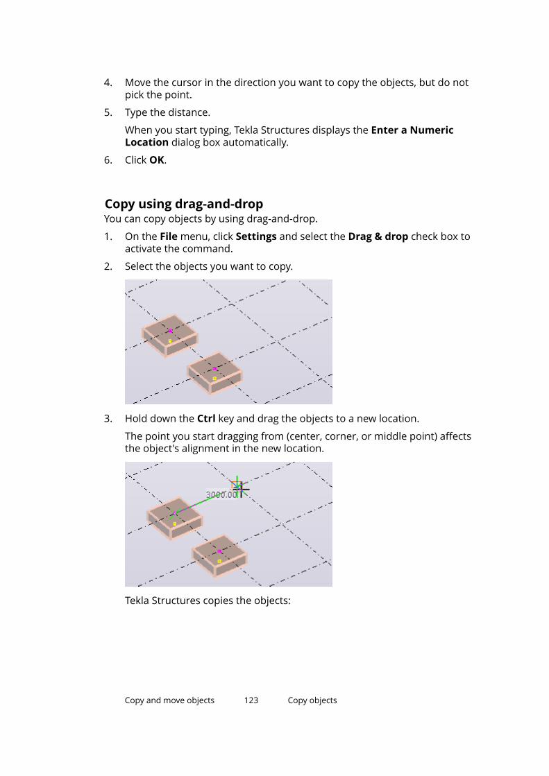
4. Move the cursor in the direction you want to copy the objects, but do notpick the point.
5. Type the distance.
When you start typing, Tekla Structures displays the Enter a NumericLocation dialog box automatically.
6. Click OK.
Copy using drag-and-dropYou can copy objects by using drag-and-drop.
1. On the File menu, click Settings and select the Drag & drop check box toactivate the command.
2. Select the objects you want to copy.
3. Hold down the Ctrl key and drag the objects to a new location.
The point you start dragging from (center, corner, or middle point) affectsthe object's alignment in the new location.
Tekla Structures copies the objects:
Copy and move objects 123 Copy objects
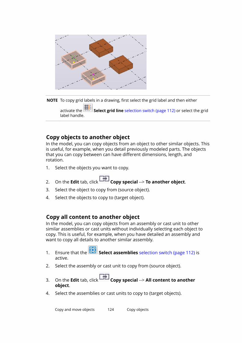
NOTE To copy grid labels in a drawing, first select the grid label and then either
activate the Select grid line selection switch (page 112) or select the gridlabel handle.
Copy objects to another objectIn the model, you can copy objects from an object to other similar objects. Thisis useful, for example, when you detail previously modeled parts. The objectsthat you can copy between can have different dimensions, length, androtation.
1. Select the objects you want to copy.
2. On the Edit tab, click Copy special --> To another object.
3. Select the object to copy from (source object).
4. Select the objects to copy to (target object).
Copy all content to another objectIn the model, you can copy objects from an assembly or cast unit to othersimilar assemblies or cast units without individually selecting each object tocopy. This is useful, for example, when you have detailed an assembly andwant to copy all details to another similar assembly.
1. Ensure that the Select assemblies selection switch (page 112) isactive.
2. Select the assembly or cast unit to copy from (source object).
3. On the Edit tab, click Copy special --> All content to anotherobject.
4. Select the assemblies or cast units to copy to (target objects).
Copy and move objects 124 Copy objects
As a result, Tekla Structures copies the following objects:
• Secondary parts
• Reinforcement, bolts, and welds
• Cuts, fittings, and edge chamfers
• Sub-assemblies
• Components
NOTE Tekla Structures does not copy pour breaks, or secondary partscreated by a component that has also created the assembly main part.If some of the objects to be copied already exist in the assembly orcast unit to copy to, Tekla Structures may create duplicate objects.Tekla Structures warns you about duplicate secondary parts,reinforcement, and sub-assemblies, but not about duplicate bolts,welds, cuts, or components.
Copy to another planeIn the model, you can copy objects from the first plane you specify to thesecond (and third, etc.) plane you specify. The position of the copied objectsrelative to the second (and third, etc.) plane remains the same as the positionof the original objects relative to the first plane.
1. Select the objects you want to copy.
2. On the Edit tab, click Copy special --> To another plane.
3. Pick the point of origin of the first plane.
4. Pick a point on the first plane in the positive x direction.
5. Pick a point on the first plane in the positive y direction.
6. Repeat steps 3–5 for all destination planes.
Copy from another modelYou can copy objects from another model based on phase numbers. Note thatTekla Structures copies secondary parts from the model only if they belong tothe same phase as their main part. This also applies to component objects.
1. On the Edit tab, click Copy special --> From another model.
The Copy from Model dialog box opens.
Copy and move objects 125 Copy objects
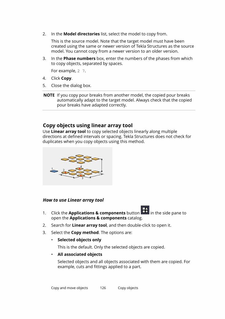
2. In the Model directories list, select the model to copy from.
This is the source model. Note that the target model must have beencreated using the same or newer version of Tekla Structures as the sourcemodel. You cannot copy from a newer version to an older version.
3. In the Phase numbers box, enter the numbers of the phases from whichto copy objects, separated by spaces.
For example, 2 7.
4. Click Copy.
5. Close the dialog box.
NOTE If you copy pour breaks from another model, the copied pour breaksautomatically adapt to the target model. Always check that the copiedpour breaks have adapted correctly.
Copy objects using linear array toolUse Linear array tool to copy selected objects linearly along multipledirections at defined intervals or spacing. Tekla Structures does not check forduplicates when you copy objects using this method.
How to use Linear array tool
1. Click the Applications & components button in the side pane toopen the Applications & components catalog.
2. Search for Linear array tool, and then double-click to open it.
3. Select the Copy method. The options are:
• Selected objects only
This is the default. Only the selected objects are copied.
• All associated objects
Selected objects and all objects associated with them are copied. Forexample, cuts and fittings applied to a part.
Copy and move objects 126 Copy objects
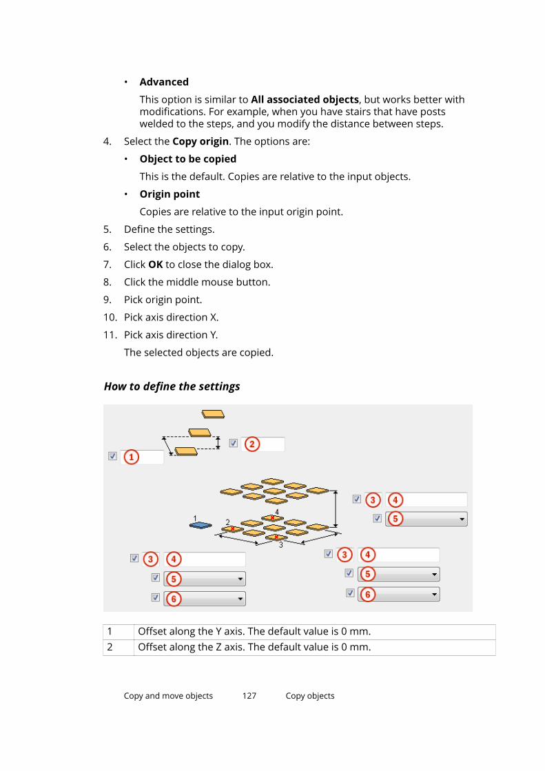
• Advanced
This option is similar to All associated objects, but works better withmodifications. For example, when you have stairs that have postswelded to the steps, and you modify the distance between steps.
4. Select the Copy origin. The options are:
• Object to be copied
This is the default. Copies are relative to the input objects.
• Origin point
Copies are relative to the input origin point.
5. Define the settings.
6. Select the objects to copy.
7. Click OK to close the dialog box.
8. Click the middle mouse button.
9. Pick origin point.
10. Pick axis direction X.
11. Pick axis direction Y.
The selected objects are copied.
How to define the settings
1 Offset along the Y axis. The default value is 0 mm.2 Offset along the Z axis. The default value is 0 mm.
Copy and move objects 127 Copy objects
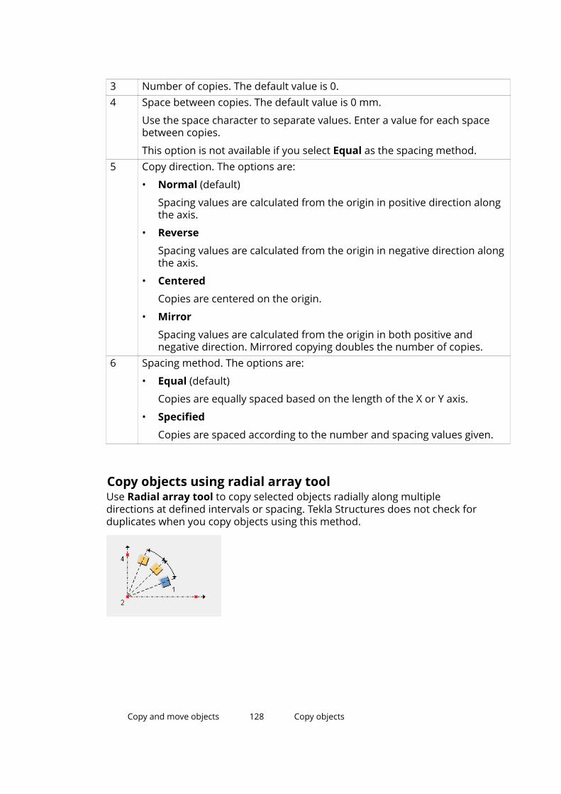
3 Number of copies. The default value is 0.4 Space between copies. The default value is 0 mm.
Use the space character to separate values. Enter a value for each spacebetween copies.
This option is not available if you select Equal as the spacing method.5 Copy direction. The options are:
• Normal (default)
Spacing values are calculated from the origin in positive direction alongthe axis.
• Reverse
Spacing values are calculated from the origin in negative direction alongthe axis.
• Centered
Copies are centered on the origin.
• Mirror
Spacing values are calculated from the origin in both positive andnegative direction. Mirrored copying doubles the number of copies.
6 Spacing method. The options are:
• Equal (default)
Copies are equally spaced based on the length of the X or Y axis.
• Specified
Copies are spaced according to the number and spacing values given.
Copy objects using radial array toolUse Radial array tool to copy selected objects radially along multipledirections at defined intervals or spacing. Tekla Structures does not check forduplicates when you copy objects using this method.
Copy and move objects 128 Copy objects
How to use Radial array tool
1. Click the Applications & components button in the side pane toopen the Applications & components catalog.
2. Search for Radial array tool, and then double-click to open it.
3. Select the Copy method. The options are:
• Selected objects only
This is the default. Only the selected objects are copied.
• All associated objects
Selected objects and all objects associated with them are copied. Forexample, cuts, welds, and bolts.
• Advanced
This option is similar to All associated objects, but works better withmodifications. For example, when you have stairs that have postswelded to the steps, and you modify the distance between steps.
4. Select the Rotate copies option.
The default is Yes.
5. Define the rotation axis.
The default is X.
6. Define the settings.
7. Select the objects to copy.
8. Click OK to close the dialog box.
9. Click the middle mouse button.
10. Pick origin point.
11. Pick axis direction X.
12. Pick axis direction Y.
The selected objects are copied.
Copy and move objects 129 Copy objects
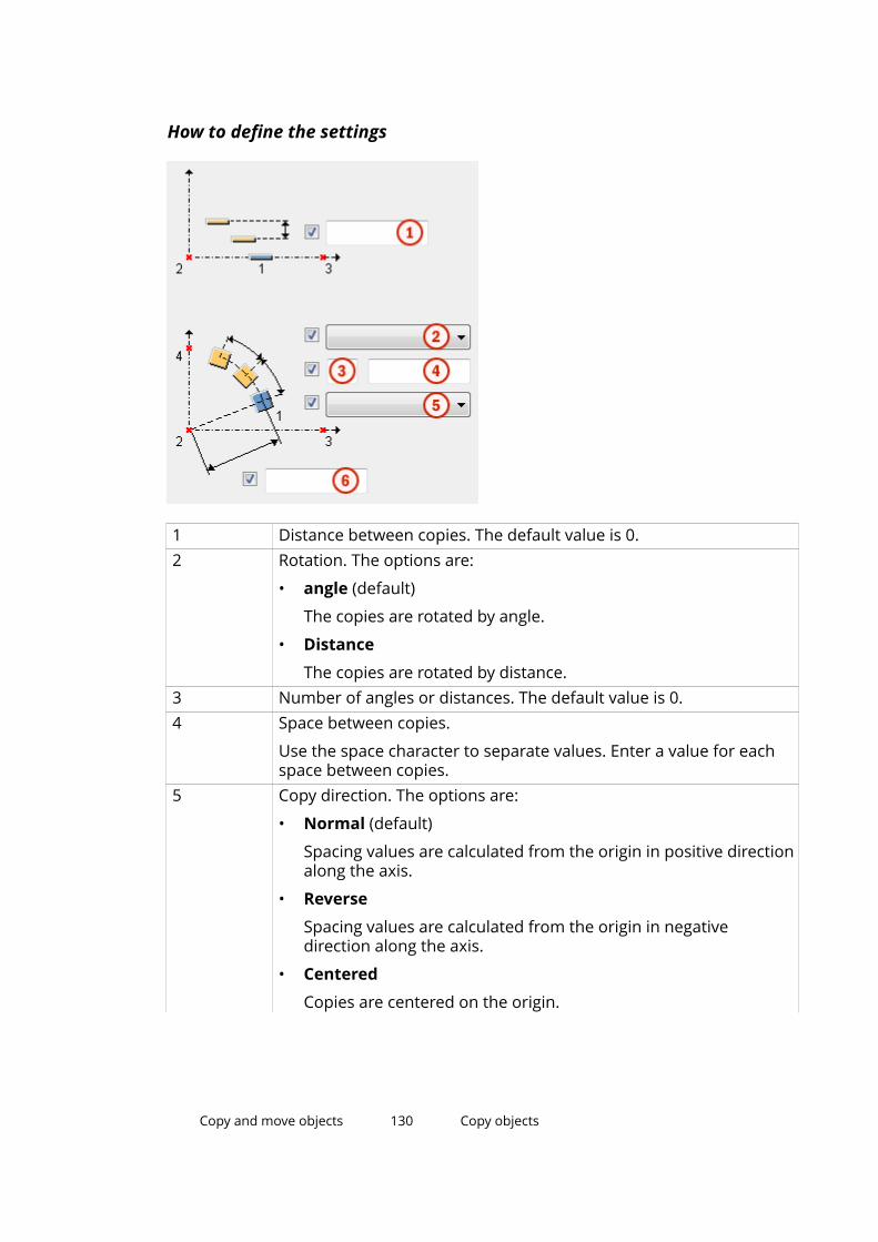
How to define the settings
1 Distance between copies. The default value is 0.2 Rotation. The options are:
• angle (default)
The copies are rotated by angle.
• Distance
The copies are rotated by distance.3 Number of angles or distances. The default value is 0.4 Space between copies.
Use the space character to separate values. Enter a value for eachspace between copies.
5 Copy direction. The options are:
• Normal (default)
Spacing values are calculated from the origin in positive directionalong the axis.
• Reverse
Spacing values are calculated from the origin in negativedirection along the axis.
• Centered
Copies are centered on the origin.
Copy and move objects 130 Copy objects
• Mirror
Spacing values are calculated from the origin in both positiveand negative direction. Mirrored copying doubles the number ofcopies.
6 Radial distance.
The radial distance should be equivalent to the distance you pickedwhen applying the component.
If the radial distance is smaller or greater than the picked distance,the spacing between the copied objects is not the same as given inthe Space between copies box (4).
Tekla Structures calculates the rotation angle according to the dialogbox values (spacing and radial distance), and the rotation angleoverrides the spacing given in the dialog box.
Copy objects using Array of objects (29) componentUse the Array of objects (29) component to copy model objects along a line. Ifyou modify the original object, Tekla Structures also changes the copiedobjects.
1. Click the Applications & components button in the side pane toopen the Applications & components catalog.
2. Search for the Array of objects (29) component, and then double-click toopen it.
3. Define the settings:
• Number of copies: Enter the number of copies you want to create.
• Spacing values: Define the spacing of the objects.
• Copy to the opposite direction: Select Yes if you want to copy in thedirection opposite to the points you pick.
• Start point for copying: Choose either the object to be copied or thefirst input point.
• Copy at equal distances (Ignore spacing values): Select Yes if youwant to create the objects at equal distances. Spacing value will beignored.
4. Click OK to save the settings.
5. Select the objects to copy.
6. Click the middle mouse button to finish selecting.
7. Pick a point to indicate the start of the line along which to arrange copiedobjects.
Copy and move objects 131 Copy objects
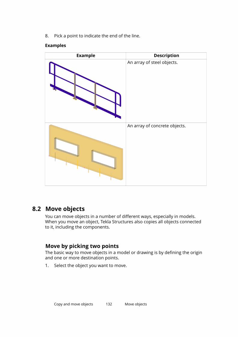
8. Pick a point to indicate the end of the line.
Examples
Example DescriptionAn array of steel objects.
An array of concrete objects.
8.2 Move objectsYou can move objects in a number of different ways, especially in models.When you move an object, Tekla Structures also copies all objects connectedto it, including the components.
Move by picking two pointsThe basic way to move objects in a model or drawing is by defining the originand one or more destination points.
1. Select the object you want to move.
Copy and move objects 132 Move objects
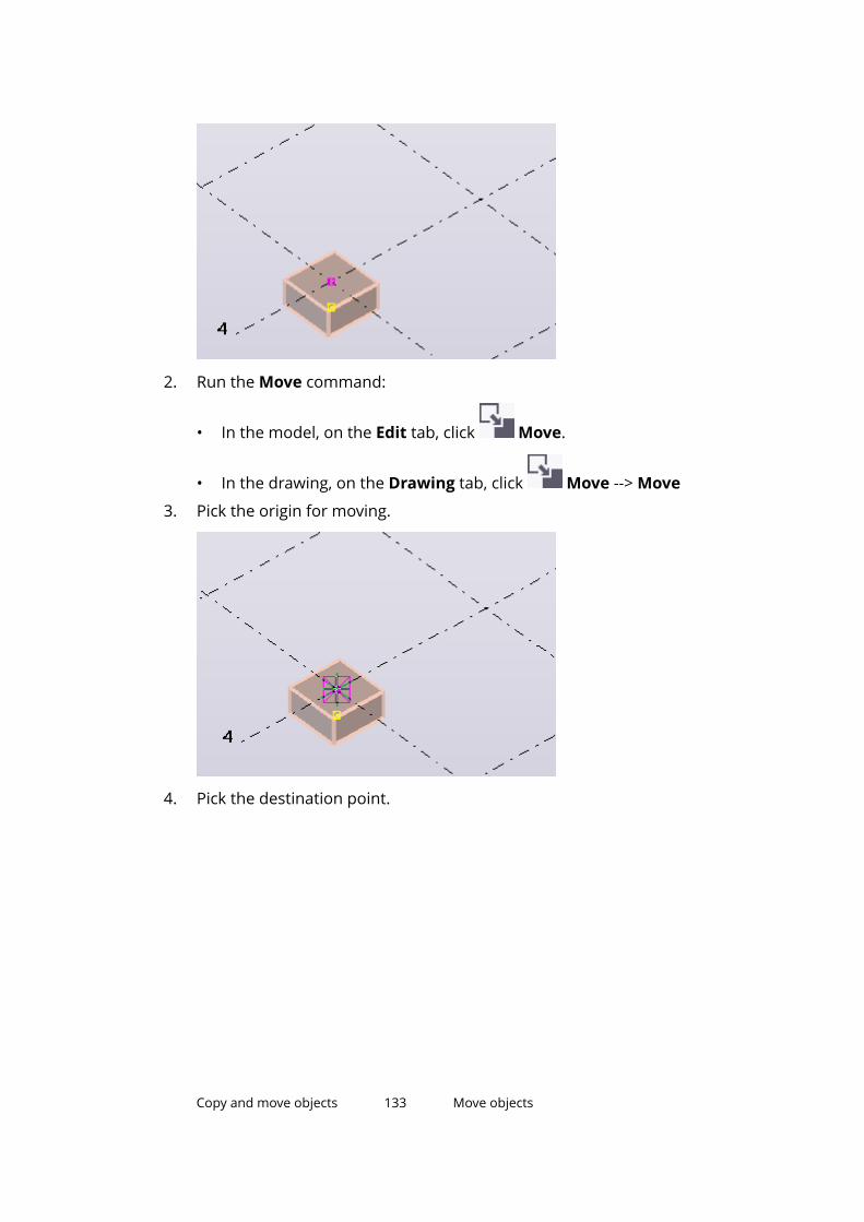
2. Run the Move command:
• In the model, on the Edit tab, click Move.
• In the drawing, on the Drawing tab, click Move --> Move
3. Pick the origin for moving.
4. Pick the destination point.
Copy and move objects 133 Move objects
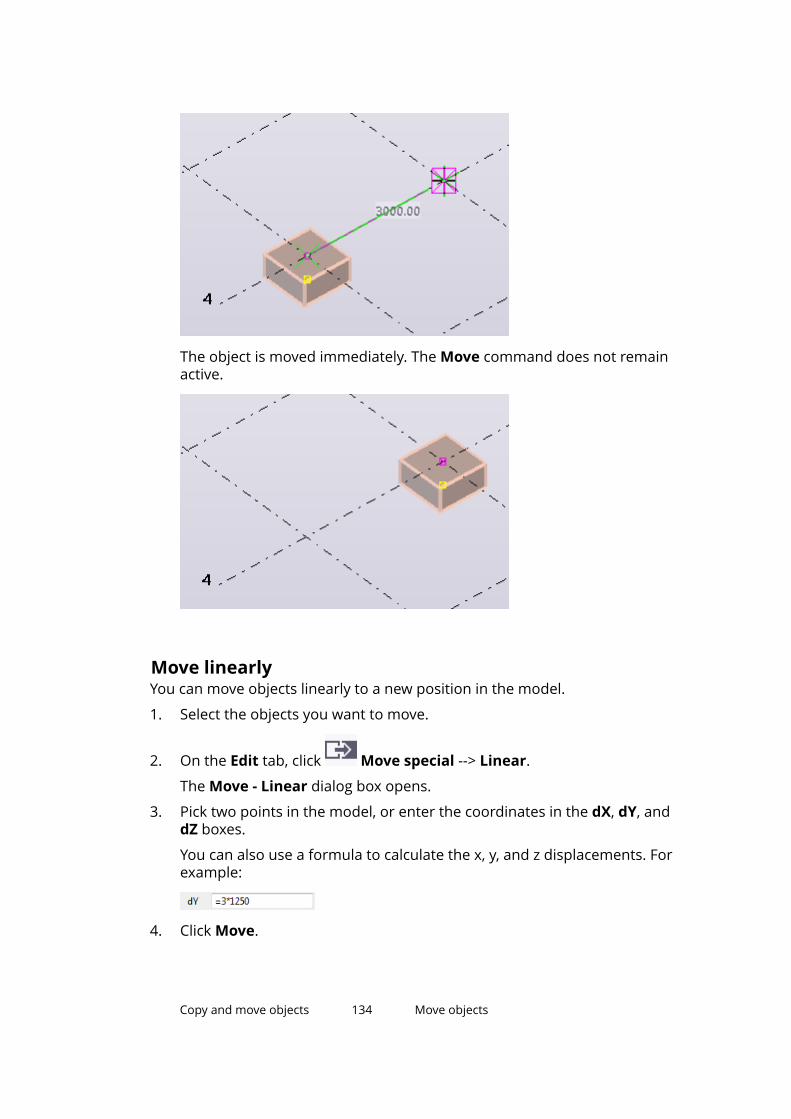
The object is moved immediately. The Move command does not remainactive.
Move linearlyYou can move objects linearly to a new position in the model.
1. Select the objects you want to move.
2. On the Edit tab, click Move special --> Linear.
The Move - Linear dialog box opens.
3. Pick two points in the model, or enter the coordinates in the dX, dY, anddZ boxes.
You can also use a formula to calculate the x, y, and z displacements. Forexample:
4. Click Move.
Copy and move objects 134 Move objects
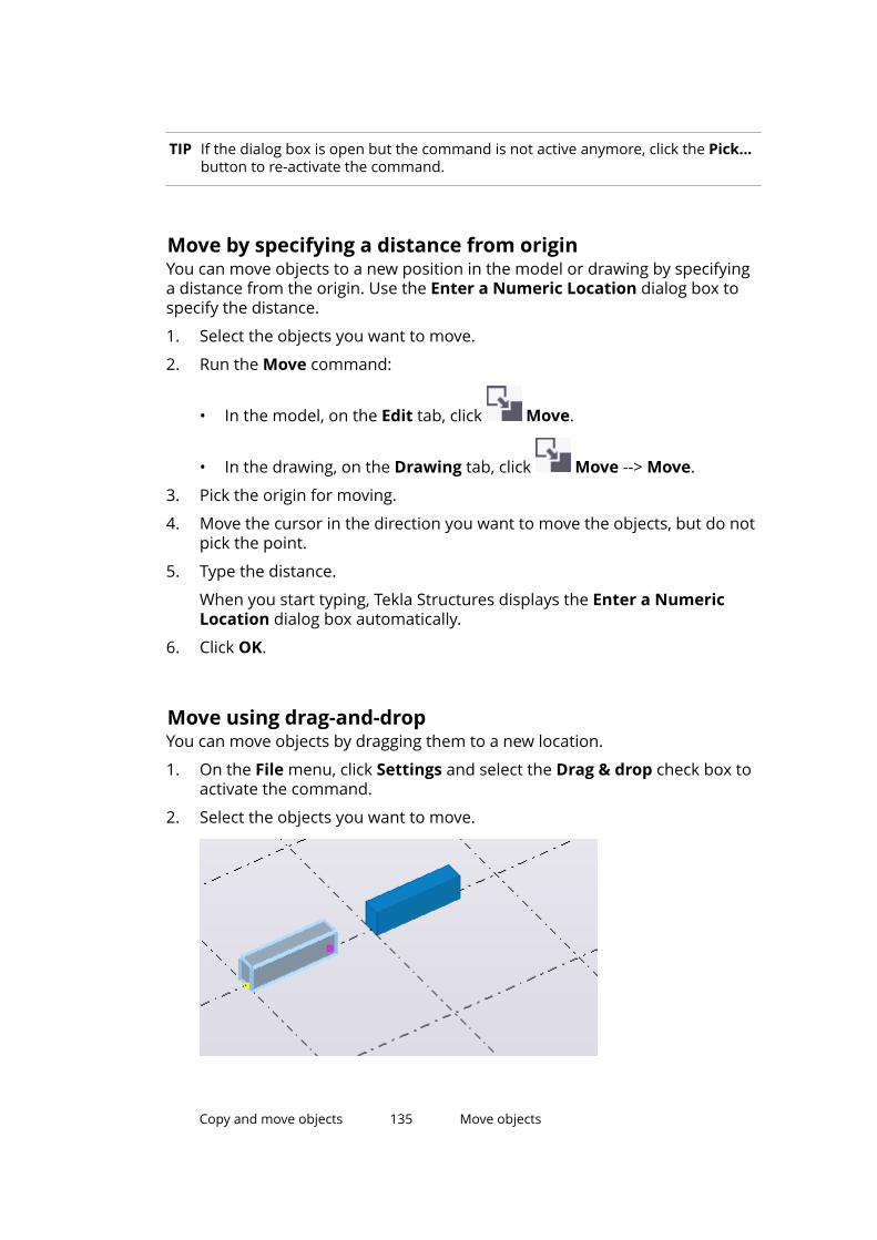
TIP If the dialog box is open but the command is not active anymore, click the Pick...button to re-activate the command.
Move by specifying a distance from originYou can move objects to a new position in the model or drawing by specifyinga distance from the origin. Use the Enter a Numeric Location dialog box tospecify the distance.
1. Select the objects you want to move.
2. Run the Move command:
• In the model, on the Edit tab, click Move.
• In the drawing, on the Drawing tab, click Move --> Move.
3. Pick the origin for moving.
4. Move the cursor in the direction you want to move the objects, but do notpick the point.
5. Type the distance.
When you start typing, Tekla Structures displays the Enter a NumericLocation dialog box automatically.
6. Click OK.
Move using drag-and-dropYou can move objects by dragging them to a new location.
1. On the File menu, click Settings and select the Drag & drop check box toactivate the command.
2. Select the objects you want to move.
Copy and move objects 135 Move objects
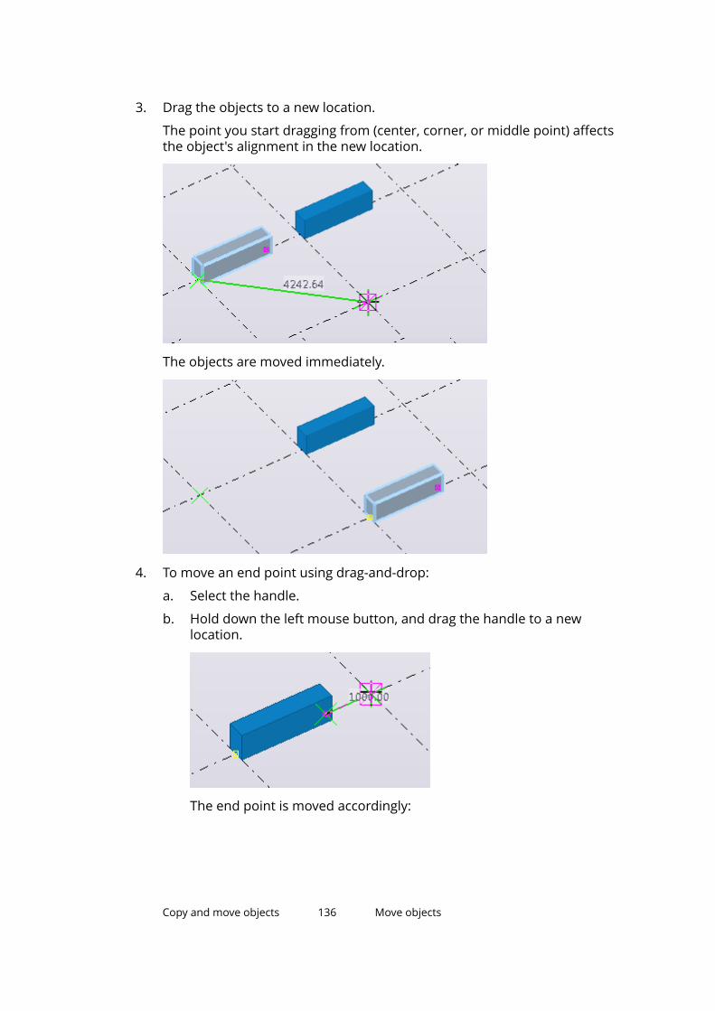
3. Drag the objects to a new location.
The point you start dragging from (center, corner, or middle point) affectsthe object's alignment in the new location.
The objects are moved immediately.
4. To move an end point using drag-and-drop:
a. Select the handle.
b. Hold down the left mouse button, and drag the handle to a newlocation.
The end point is moved accordingly:
Copy and move objects 136 Move objects
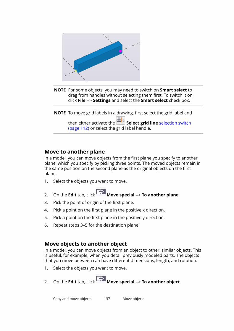
NOTE For some objects, you may need to switch on Smart select todrag from handles without selecting them first. To switch it on,click File --> Settings and select the Smart select check box.
NOTE To move grid labels in a drawing, first select the grid label and
then either activate the Select grid line selection switch(page 112) or select the grid label handle.
Move to another planeIn a model, you can move objects from the first plane you specify to anotherplane, which you specify by picking three points. The moved objects remain inthe same position on the second plane as the original objects on the firstplane.
1. Select the objects you want to move.
2. On the Edit tab, click Move special --> To another plane.
3. Pick the point of origin of the first plane.
4. Pick a point on the first plane in the positive x direction.
5. Pick a point on the first plane in the positive y direction.
6. Repeat steps 3–5 for the destination plane.
Move objects to another objectIn a model, you can move objects from an object to other, similar objects. Thisis useful, for example, when you detail previously modeled parts. The objectsthat you move between can have different dimensions, length, and rotation.
1. Select the objects you want to move.
2. On the Edit tab, click Move special --> To another object.
Copy and move objects 137 Move objects
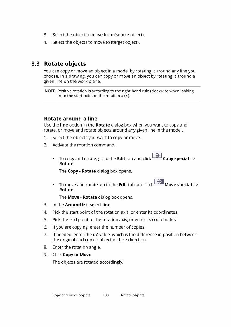
3. Select the object to move from (source object).
4. Select the objects to move to (target object).
8.3 Rotate objectsYou can copy or move an object in a model by rotating it around any line youchoose. In a drawing, you can copy or move an object by rotating it around agiven line on the work plane.
NOTE Positive rotation is according to the right-hand rule (clockwise when lookingfrom the start point of the rotation axis).
Rotate around a lineUse the line option in the Rotate dialog box when you want to copy androtate, or move and rotate objects around any given line in the model.
1. Select the objects you want to copy or move.
2. Activate the rotation command.
• To copy and rotate, go to the Edit tab and click Copy special -->Rotate.
The Copy - Rotate dialog box opens.
• To move and rotate, go to the Edit tab and click Move special -->Rotate.
The Move - Rotate dialog box opens.
3. In the Around list, select line.
4. Pick the start point of the rotation axis, or enter its coordinates.
5. Pick the end point of the rotation axis, or enter its coordinates.
6. If you are copying, enter the number of copies.
7. If needed, enter the dZ value, which is the difference in position betweenthe original and copied object in the z direction.
8. Enter the rotation angle.
9. Click Copy or Move.
The objects are rotated accordingly.
Copy and move objects 138 Rotate objects
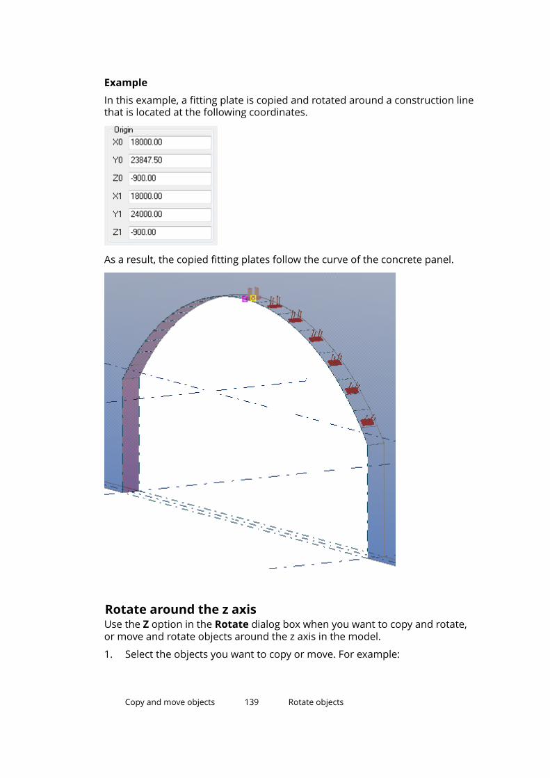
Example
In this example, a fitting plate is copied and rotated around a construction linethat is located at the following coordinates.
As a result, the copied fitting plates follow the curve of the concrete panel.
Rotate around the z axisUse the Z option in the Rotate dialog box when you want to copy and rotate,or move and rotate objects around the z axis in the model.
1. Select the objects you want to copy or move. For example:
Copy and move objects 139 Rotate objects
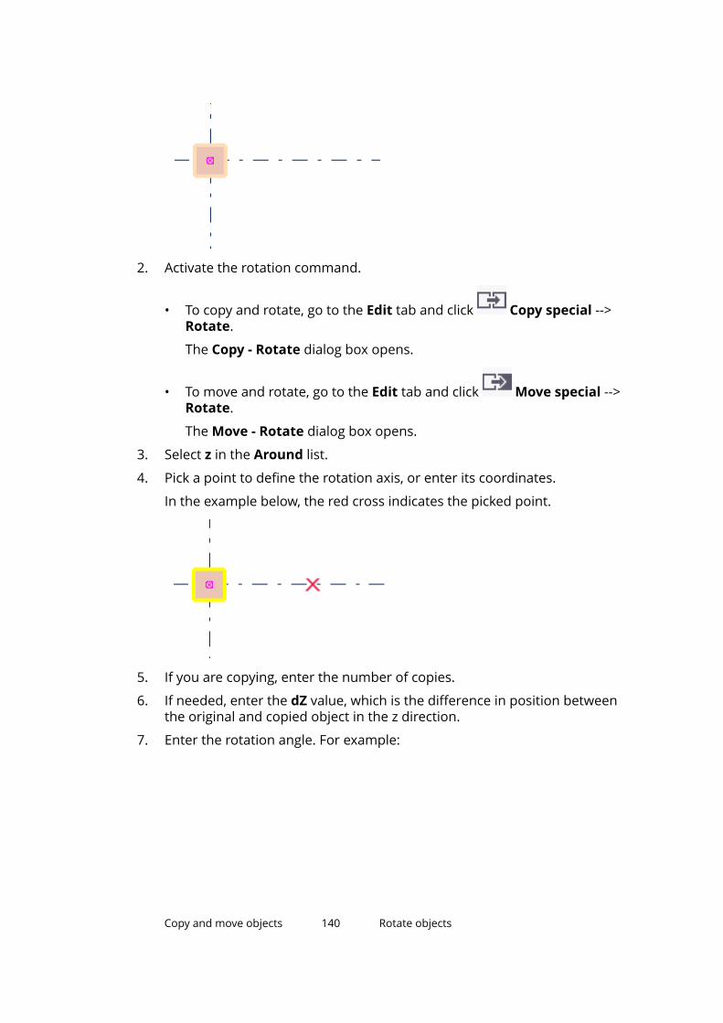
2. Activate the rotation command.
• To copy and rotate, go to the Edit tab and click Copy special -->Rotate.
The Copy - Rotate dialog box opens.
• To move and rotate, go to the Edit tab and click Move special -->Rotate.
The Move - Rotate dialog box opens.
3. Select z in the Around list.
4. Pick a point to define the rotation axis, or enter its coordinates.
In the example below, the red cross indicates the picked point.
5. If you are copying, enter the number of copies.
6. If needed, enter the dZ value, which is the difference in position betweenthe original and copied object in the z direction.
7. Enter the rotation angle. For example:
Copy and move objects 140 Rotate objects

8. Click Copy or Move.
The objects are rotated accordingly.
Rotate drawing objectsUse this option when you want to rotate drawing objects on the work plane.
1. Select the objects you want to copy or move.
2. Activate the rotation command.
• To copy and rotate, go to the Drawing tab and click Copy -->Rotate.
The Copy - Rotate dialog box opens.
• To move and rotate, go to the Drawing tab and click Move -->Rotate.
The Move - Rotate dialog box opens.
3. Pick a point, or enter its coordinates.
4. If you are copying, enter the number of copies.
5. Enter the rotation angle.
6. Click Copy or Move.
Copy and move objects 141 Rotate objects
8.4 Mirror objectsWhen you copy or move objects, you can mirror them through a plane that isperpendicular to the work plane and passes through a line you specify.
Note that Tekla Structures cannot create mirrored copies of componentproperties. The Copy special > Mirror command does not fully mirror objectsif they include components that contain, for example, asymmetricallypositioned parts.
Mirror model objectsUse this method to copy and mirror, or move and mirror objects in a model.
1. Select the objects you want to copy or move.
2. Activate the mirroring command.
• To copy and mirror, go to the Edit tab and click Copy special -->Mirror.
The Copy - Mirror dialog box opens.
• To move and mirror, go to the Edit tab and click Move special -->Mirror.
The Move - Mirror dialog box opens.
3. Pick the start point of the mirroring plane, or enter its coordinates.
4. Pick the end point of the mirroring plane, or enter its coordinates.
5. Enter the angle.
6. Click Copy or Move.
Mirror drawing objectsUse this method to copy and mirror, or move and mirror objects in a drawing.
1. Select the objects you want to copy or move.
2. Activate the mirroring command.
• To copy and mirror, go to the Edit tab and click Copy special -->Mirror.
The Copy - Mirror dialog box opens.
Copy and move objects 142 Mirror objects
• To move and mirror, go to the Edit tab and click Move special -->Mirror.
The Move - Mirror dialog box opens.
3. Pick the start point of the mirroring plane, or enter its coordinates.
4. Pick the end point of the mirroring plane, or enter its coordinates.
5. Enter the angle.
6. Click Copy or Move.
Copy and move objects 143 Mirror objects
9 Filter objects
Use filters to restrict what can be selected or what is visible in a view. You cancreate filters of your own, or you can use any of the standard filters availablein Tekla Structures.
Here are some examples of what filters can be used for:
• To select a large number of objects
Use selection filters when you need to change a specific object propertythat is common for many objects. The rest of the objects will not beaffected, even if you try to include them in the selection.
• To check the model
Use view filters to ensure that beams are called beams, columns are calledcolumns, and so on. You can highlight several groups of objects, one at atime, to check that all required objects are included in a given group.
• To hide objects
Use view filters to temporarily hide the columns in a view so that it easierto select all the beams, for example.
• To find objects
You can create a selection filter to find all locations where ½” reinforcingbars are in the model, for example. Once the filter is active, you can makean area selection that includes the entire model. All specified reinforcingbars become selected, but the other objects will not be affected.
See also
Use existing filters (page 144)
Create new filters (page 147)
Filtering techniques (page 151)
Examples of filters (page 169)
Filter objects 144 Use existing filters
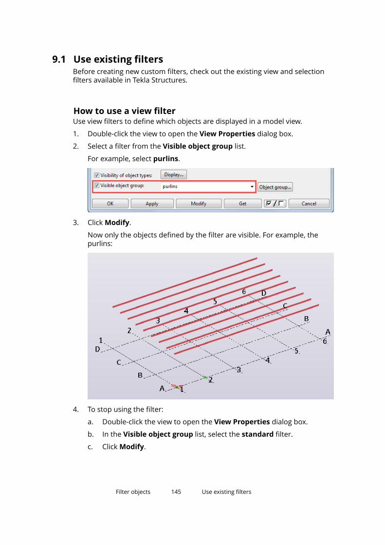
9.1 Use existing filtersBefore creating new custom filters, check out the existing view and selectionfilters available in Tekla Structures.
How to use a view filterUse view filters to define which objects are displayed in a model view.
1. Double-click the view to open the View Properties dialog box.
2. Select a filter from the Visible object group list.
For example, select purlins.
3. Click Modify.
Now only the objects defined by the filter are visible. For example, thepurlins:
4. To stop using the filter:
a. Double-click the view to open the View Properties dialog box.
b. In the Visible object group list, select the standard filter.
c. Click Modify.
Filter objects 145 Use existing filters
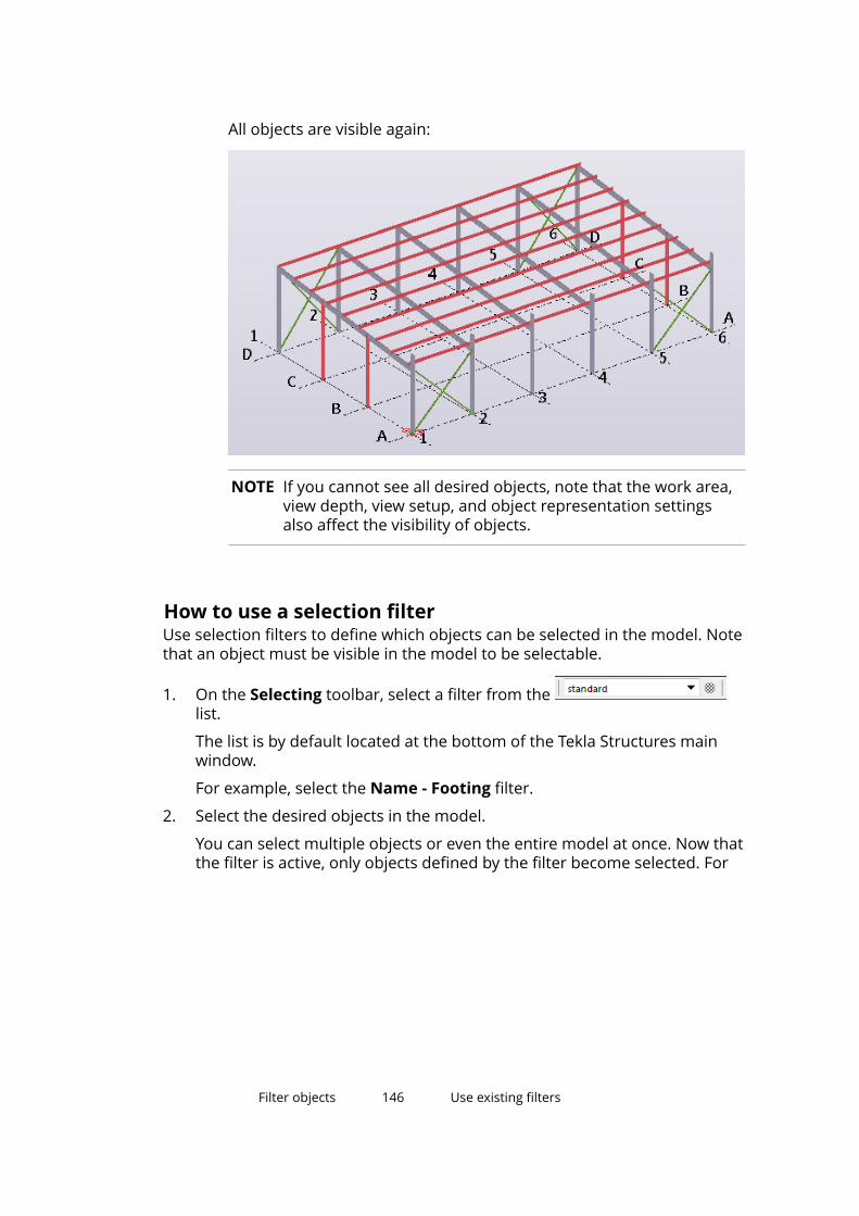
All objects are visible again:
NOTE If you cannot see all desired objects, note that the work area,view depth, view setup, and object representation settingsalso affect the visibility of objects.
How to use a selection filterUse selection filters to define which objects can be selected in the model. Notethat an object must be visible in the model to be selectable.
1. On the Selecting toolbar, select a filter from the list.
The list is by default located at the bottom of the Tekla Structures mainwindow.
For example, select the Name - Footing filter.
2. Select the desired objects in the model.
You can select multiple objects or even the entire model at once. Now thatthe filter is active, only objects defined by the filter become selected. For
Filter objects 146 Use existing filters
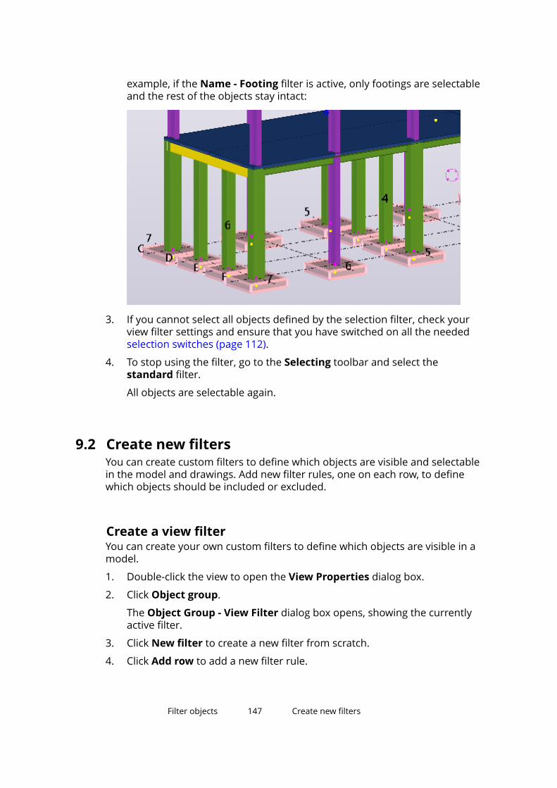
example, if the Name - Footing filter is active, only footings are selectableand the rest of the objects stay intact:
3. If you cannot select all objects defined by the selection filter, check yourview filter settings and ensure that you have switched on all the neededselection switches (page 112).
4. To stop using the filter, go to the Selecting toolbar and select thestandard filter.
All objects are selectable again.
9.2 Create new filtersYou can create custom filters to define which objects are visible and selectablein the model and drawings. Add new filter rules, one on each row, to definewhich objects should be included or excluded.
Create a view filterYou can create your own custom filters to define which objects are visible in amodel.
1. Double-click the view to open the View Properties dialog box.
2. Click Object group.
The Object Group - View Filter dialog box opens, showing the currentlyactive filter.
3. Click New filter to create a new filter from scratch.
4. Click Add row to add a new filter rule.
Filter objects 147 Create new filters
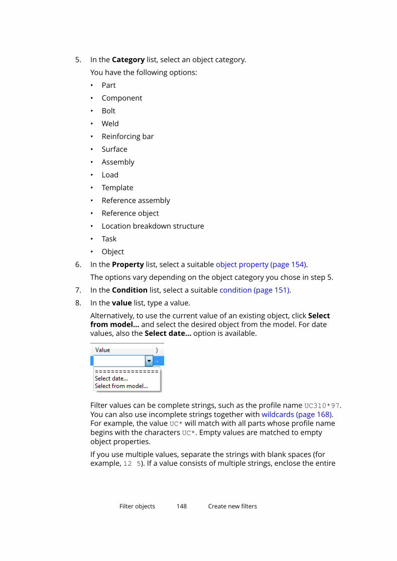
5. In the Category list, select an object category.
You have the following options:
• Part
• Component
• Bolt
• Weld
• Reinforcing bar
• Surface
• Assembly
• Load
• Template
• Reference assembly
• Reference object
• Location breakdown structure
• Task
• Object
6. In the Property list, select a suitable object property (page 154).
The options vary depending on the object category you chose in step 5.
7. In the Condition list, select a suitable condition (page 151).
8. In the value list, type a value.
Alternatively, to use the current value of an existing object, click Selectfrom model... and select the desired object from the model. For datevalues, also the Select date... option is available.
Filter values can be complete strings, such as the profile name UC310*97.You can also use incomplete strings together with wildcards (page 168).For example, the value UC* will match with all parts whose profile namebegins with the characters UC*. Empty values are matched to emptyobject properties.
If you use multiple values, separate the strings with blank spaces (forexample, 12 5). If a value consists of multiple strings, enclose the entire
Filter objects 148 Create new filters
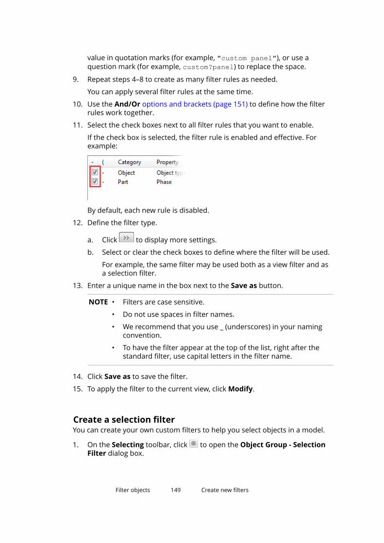
value in quotation marks (for example, "custom panel"), or use aquestion mark (for example, custom?panel) to replace the space.
9. Repeat steps 4–8 to create as many filter rules as needed.
You can apply several filter rules at the same time.
10. Use the And/Or options and brackets (page 151) to define how the filterrules work together.
11. Select the check boxes next to all filter rules that you want to enable.
If the check box is selected, the filter rule is enabled and effective. Forexample:
By default, each new rule is disabled.
12. Define the filter type.
a. Click to display more settings.
b. Select or clear the check boxes to define where the filter will be used.
For example, the same filter may be used both as a view filter and asa selection filter.
13. Enter a unique name in the box next to the Save as button.
NOTE • Filters are case sensitive.
• Do not use spaces in filter names.
• We recommend that you use _ (underscores) in your namingconvention.
• To have the filter appear at the top of the list, right after thestandard filter, use capital letters in the filter name.
14. Click Save as to save the filter.
15. To apply the filter to the current view, click Modify.
Create a selection filterYou can create your own custom filters to help you select objects in a model.
1. On the Selecting toolbar, click to open the Object Group - SelectionFilter dialog box.
Filter objects 149 Create new filters
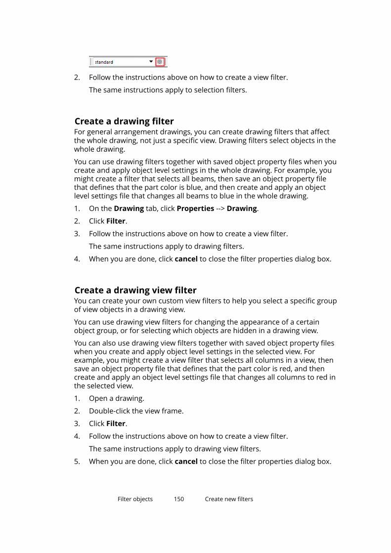
2. Follow the instructions above on how to create a view filter.
The same instructions apply to selection filters.
Create a drawing filterFor general arrangement drawings, you can create drawing filters that affectthe whole drawing, not just a specific view. Drawing filters select objects in thewhole drawing.
You can use drawing filters together with saved object property files when youcreate and apply object level settings in the whole drawing. For example, youmight create a filter that selects all beams, then save an object property filethat defines that the part color is blue, and then create and apply an objectlevel settings file that changes all beams to blue in the whole drawing.
1. On the Drawing tab, click Properties --> Drawing.
2. Click Filter.
3. Follow the instructions above on how to create a view filter.
The same instructions apply to drawing filters.
4. When you are done, click cancel to close the filter properties dialog box.
Create a drawing view filterYou can create your own custom view filters to help you select a specific groupof view objects in a drawing view.
You can use drawing view filters for changing the appearance of a certainobject group, or for selecting which objects are hidden in a drawing view.
You can also use drawing view filters together with saved object property fileswhen you create and apply object level settings in the selected view. Forexample, you might create a view filter that selects all columns in a view, thensave an object property file that defines that the part color is red, and thencreate and apply an object level settings file that changes all columns to red inthe selected view.
1. Open a drawing.
2. Double-click the view frame.
3. Click Filter.
4. Follow the instructions above on how to create a view filter.
The same instructions apply to drawing view filters.
5. When you are done, click cancel to close the filter properties dialog box.
Filter objects 150 Create new filters
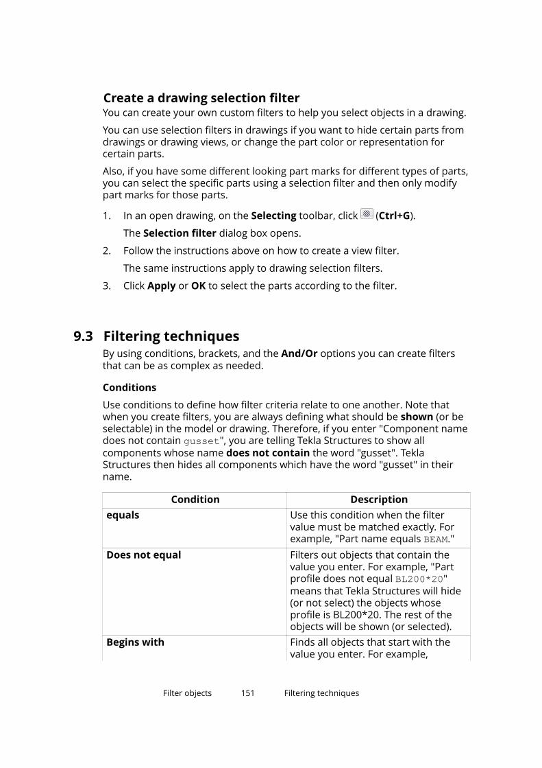
Create a drawing selection filterYou can create your own custom filters to help you select objects in a drawing.
You can use selection filters in drawings if you want to hide certain parts fromdrawings or drawing views, or change the part color or representation forcertain parts.
Also, if you have some different looking part marks for different types of parts,you can select the specific parts using a selection filter and then only modifypart marks for those parts.
1. In an open drawing, on the Selecting toolbar, click (Ctrl+G).
The Selection filter dialog box opens.
2. Follow the instructions above on how to create a view filter.
The same instructions apply to drawing selection filters.
3. Click Apply or OK to select the parts according to the filter.
9.3 Filtering techniquesBy using conditions, brackets, and the And/Or options you can create filtersthat can be as complex as needed.
Conditions
Use conditions to define how filter criteria relate to one another. Note thatwhen you create filters, you are always defining what should be shown (or beselectable) in the model or drawing. Therefore, if you enter "Component namedoes not contain gusset", you are telling Tekla Structures to show allcomponents whose name does not contain the word "gusset". TeklaStructures then hides all components which have the word "gusset" in theirname.
Condition Descriptionequals Use this condition when the filter
value must be matched exactly. Forexample, "Part name equals BEAM."
Does not equal Filters out objects that contain thevalue you enter. For example, "Partprofile does not equal BL200*20"means that Tekla Structures will hide(or not select) the objects whoseprofile is BL200*20. The rest of theobjects will be shown (or selected).
Begins with Finds all objects that start with thevalue you enter. For example,
Filter objects 151 Filtering techniques
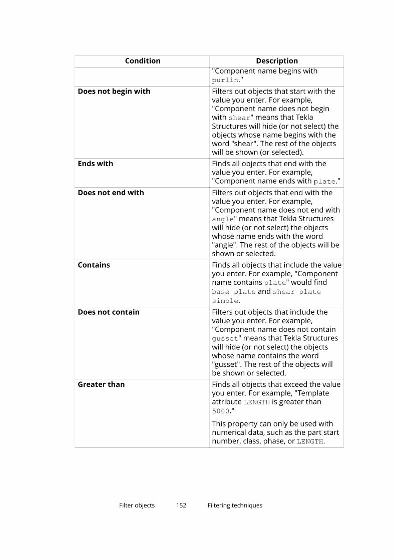
Condition Description"Component name begins withpurlin."
Does not begin with Filters out objects that start with thevalue you enter. For example,"Component name does not beginwith shear" means that TeklaStructures will hide (or not select) theobjects whose name begins with theword "shear". The rest of the objectswill be shown (or selected).
Ends with Finds all objects that end with thevalue you enter. For example,"Component name ends with plate."
Does not end with Filters out objects that end with thevalue you enter. For example,"Component name does not end withangle" means that Tekla Structureswill hide (or not select) the objectswhose name ends with the word"angle". The rest of the objects will beshown or selected.
Contains Finds all objects that include the valueyou enter. For example, "Componentname contains plate" would findbase plate and shear platesimple.
Does not contain Filters out objects that include thevalue you enter. For example,"Component name does not containgusset" means that Tekla Structureswill hide (or not select) the objectswhose name contains the word"gusset". The rest of the objects willbe shown or selected.
Greater than Finds all objects that exceed the valueyou enter. For example, "Templateattribute LENGTH is greater than5000."
This property can only be used withnumerical data, such as the part startnumber, class, phase, or LENGTH.
Filter objects 152 Filtering techniques
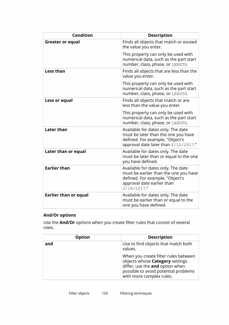
Condition DescriptionGreater or equal Finds all objects that match or exceed
the value you enter.
This property can only be used withnumerical data, such as the part startnumber, class, phase, or LENGTH.
Less than Finds all objects that are less than thevalue you enter.
This property can only be used withnumerical data, such as the part startnumber, class, phase, or LENGTH.
Less or equal Finds all objects that match or areless than the value you enter.
This property can only be used withnumerical data, such as the part startnumber, class, phase, or LENGTH.
Later than Available for dates only. The datemust be later than the one you havedefined. For example, "Object'sapproval date later than 4/10/2017."
Later than or equal Available for dates only. The datemust be later than or equal to the oneyou have defined.
Earlier than Available for dates only. The datemust be earlier than the one you havedefined. For example, "Object'sapproval date earlier than2/18/2017."
Earlier than or equal Available for dates only. The datemust be earlier than or equal to theone you have defined.
And/Or options
Use the And/Or options when you create filter rules that consist of severalrows.
Option Descriptionand Use to find objects that match both
values.
When you create filter rules betweenobjects whose Category settingsdiffer, use the and option whenpossible to avoid potential problemswith more complex rules.
Filter objects 153 Filtering techniques
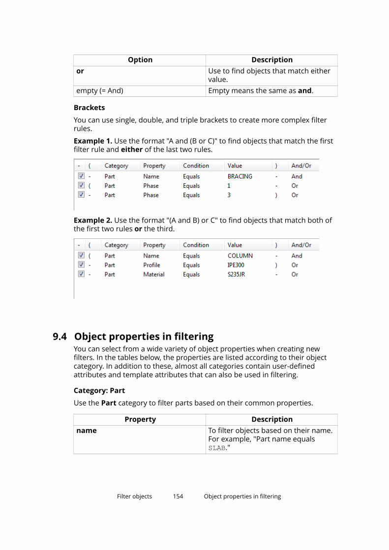
Option Descriptionor Use to find objects that match either
value.empty (= And) Empty means the same as and.
Brackets
You can use single, double, and triple brackets to create more complex filterrules.
Example 1. Use the format "A and (B or C)" to find objects that match the firstfilter rule and either of the last two rules.
Example 2. Use the format "(A and B) or C" to find objects that match both ofthe first two rules or the third.
9.4 Object properties in filteringYou can select from a wide variety of object properties when creating newfilters. In the tables below, the properties are listed according to their objectcategory. In addition to these, almost all categories contain user-definedattributes and template attributes that can also be used in filtering.
Category: Part
Use the Part category to filter parts based on their common properties.
Property Descriptionname To filter objects based on their name.
For example, "Part name equalsSLAB."
Filter objects 154 Object properties in filtering
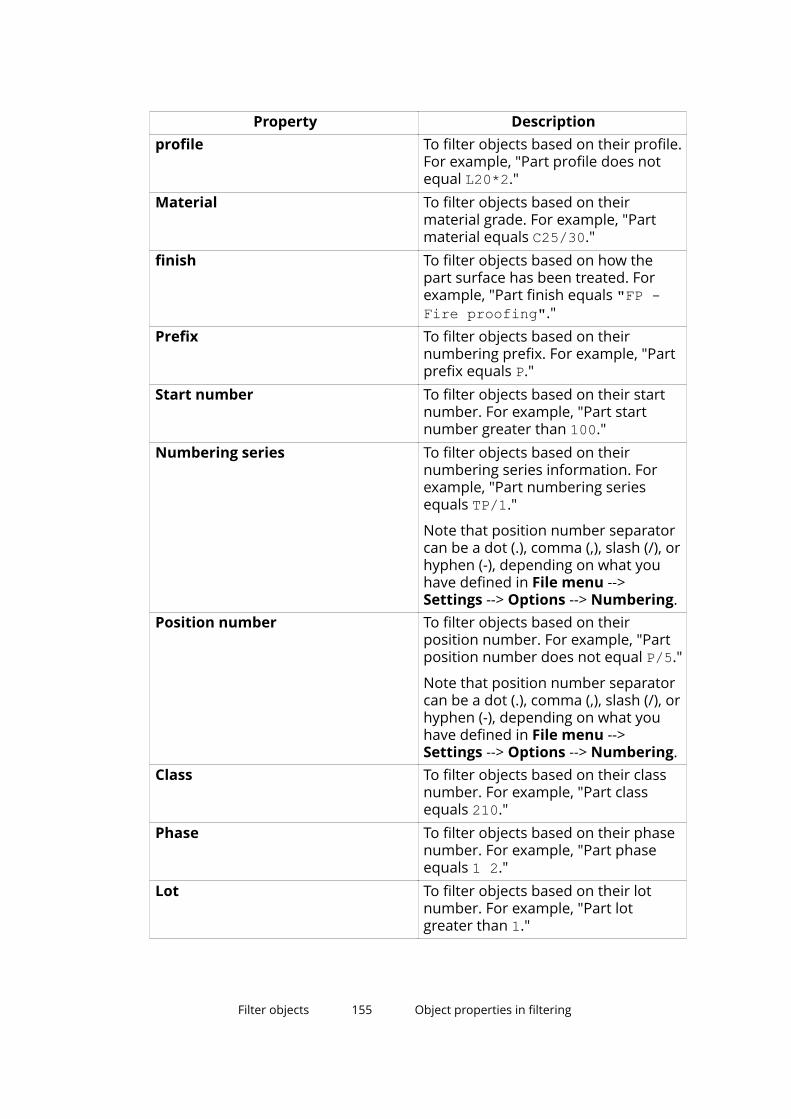
Property Descriptionprofile To filter objects based on their profile.
For example, "Part profile does notequal L20*2."
Material To filter objects based on theirmaterial grade. For example, "Partmaterial equals C25/30."
finish To filter objects based on how thepart surface has been treated. Forexample, "Part finish equals "FP -Fire proofing"."
Prefix To filter objects based on theirnumbering prefix. For example, "Partprefix equals P."
Start number To filter objects based on their startnumber. For example, "Part startnumber greater than 100."
Numbering series To filter objects based on theirnumbering series information. Forexample, "Part numbering seriesequals TP/1."
Note that position number separatorcan be a dot (.), comma (,), slash (/), orhyphen (-), depending on what youhave defined in File menu -->Settings --> Options --> Numbering.
Position number To filter objects based on theirposition number. For example, "Partposition number does not equal P/5."
Note that position number separatorcan be a dot (.), comma (,), slash (/), orhyphen (-), depending on what youhave defined in File menu -->Settings --> Options --> Numbering.
Class To filter objects based on their classnumber. For example, "Part classequals 210."
Phase To filter objects based on their phasenumber. For example, "Part phaseequals 1 2."
Lot To filter objects based on their lotnumber. For example, "Part lotgreater than 1."
Filter objects 155 Object properties in filtering
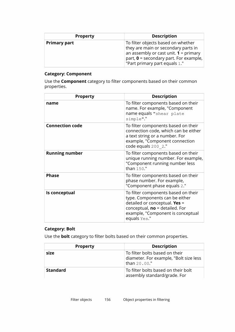
Property DescriptionPrimary part To filter objects based on whether
they are main or secondary parts inan assembly or cast unit. 1 = primarypart, 0 = secondary part. For example,"Part primary part equals 1."
Category: Component
Use the Component category to filter components based on their commonproperties.
Property Descriptionname To filter components based on their
name. For example, "Componentname equals "shear platesimple"."
Connection code To filter components based on theirconnection code, which can be eithera text string or a number. Forexample, "Component connectioncode equals 200_2."
Running number To filter components based on theirunique running number. For example,"Component running number lessthan 150."
Phase To filter components based on theirphase number. For example,"Component phase equals 2."
Is conceptual To filter components based on theirtype. Components can be eitherdetailed or conceptual. Yes =conceptual, no = detailed. Forexample, "Component is conceptualequals Yes."
Category: Bolt
Use the bolt category to filter bolts based on their common properties.
Property Descriptionsize To filter bolts based on their
diameter. For example, "Bolt size lessthan 20.00."
Standard To filter bolts based on their boltassembly standard/grade. For
Filter objects 156 Object properties in filtering
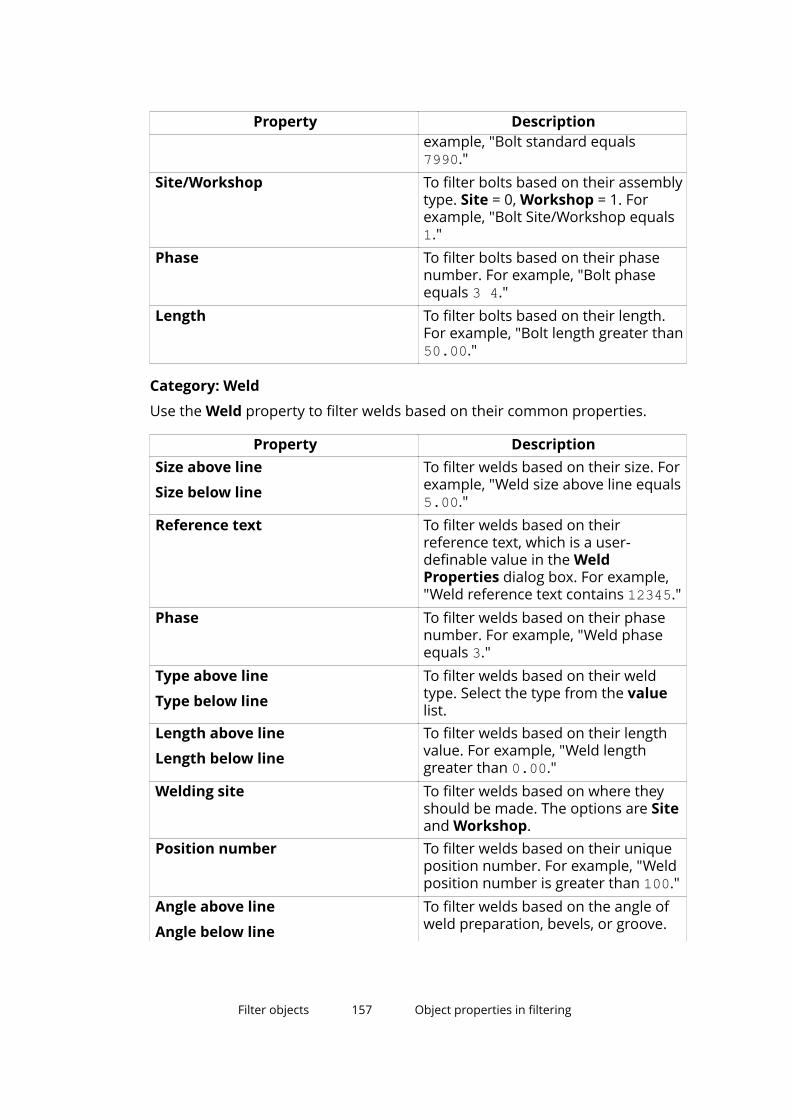
Property Descriptionexample, "Bolt standard equals7990."
Site/Workshop To filter bolts based on their assemblytype. Site = 0, Workshop = 1. Forexample, "Bolt Site/Workshop equals1."
Phase To filter bolts based on their phasenumber. For example, "Bolt phaseequals 3 4."
Length To filter bolts based on their length.For example, "Bolt length greater than50.00."
Category: Weld
Use the Weld property to filter welds based on their common properties.
Property DescriptionSize above line
Size below line
To filter welds based on their size. Forexample, "Weld size above line equals5.00."
Reference text To filter welds based on theirreference text, which is a user-definable value in the WeldProperties dialog box. For example,"Weld reference text contains 12345."
Phase To filter welds based on their phasenumber. For example, "Weld phaseequals 3."
Type above line
Type below line
To filter welds based on their weldtype. Select the type from the valuelist.
Length above line
Length below line
To filter welds based on their lengthvalue. For example, "Weld lengthgreater than 0.00."
Welding site To filter welds based on where theyshould be made. The options are Siteand Workshop.
Position number To filter welds based on their uniqueposition number. For example, "Weldposition number is greater than 100."
Angle above line
Angle below line
To filter welds based on the angle ofweld preparation, bevels, or groove.
Filter objects 157 Object properties in filtering
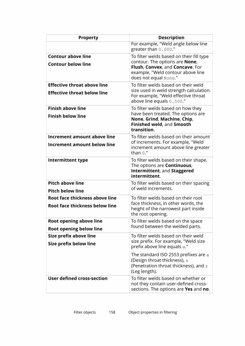
Property DescriptionFor example, "Weld angle below linegreater than 0.000."
Contour above line
Contour below line
To filter welds based on their fill typecontour. The options are None,Flush, Convex, and Concave. Forexample, "Weld contour above linedoes not equal None."
Effective throat above line
Effective throat below line
To filter welds based on their weldsize used in weld strength calculation.For example, "Weld effective throatabove line equals 0.500."
Finish above line
Finish below line
To filter welds based on how theyhave been treated. The options areNone, Grind, Machine, Chip,Finished weld, and Smoothtransition.
Increment amount above line
Increment amount below line
To filter welds based on their amountof increments. For example, "Weldincrement amount above line greaterthan 0."
Intermittent type To filter welds based on their shape.The options are Continuous,Intermittent, and Staggeredintermittent.
Pitch above line
Pitch below line
To filter welds based on their spacingof weld increments.
Root face thickness above line
Root face thickness below line
To filter welds based on their rootface thickness, in other words, theheight of the narrowest part insidethe root opening.
Root opening above line
Root opening below line
To filter welds based on the spacefound between the welded parts.
Size prefix above line
Size prefix below line
To filter welds based on their weldsize prefix. For example, "Weld sizeprefix above line equals a."
The standard ISO 2553 prefixes are a(Design throat thickness), s(Penetration throat thickness), and z(Leg length).
User defined cross-section To filter welds based on whether ornot they contain user-defined cross-sections. The options are Yes and no.
Filter objects 158 Object properties in filtering

Property DescriptionElectrode classification To filter welds based on their weld
electrode classification. The optionsare (empty), 35, 52, 50, E60XX, E70XX,E80XX, and E90XX.
Electrode strength To filter welds based on theirelectrode strength. For example,"Weld electrode strength greater than0.000."
Process type To filter welds based on their weldingprocess type. The options are SMAW,SAW, GMAW, FCAW, ESW, and EGW.
NDT inspection To filter welds based on their non-destructive testing and inspectionlevel. The options are A, B, C, D, andE.
Is around weld To filter welds based on whether onlyone edge or the entire perimeter of aface is welded. no = edge, Yes =around.
Category: Reinforcing bar
Use the Reinforcing bar category to filter reinforcing bars based on theircommon properties.
Property Descriptionname To filter reinforcing bars based on
their name. For example, "Reinforcingbar name equals "STIRRUP"."
Class To filter reinforcing bars based ontheir class number. For example,"Reinforcing bar class equals 3."
size To filter reinforcing bars based ontheir size. The size property dependson the environment and may containletters and special characters. Forexample, in the US imperialenvironment, "Reinforcing bar sizeequals #18."
diameter To filter reinforcing bars based ontheir diameter. Diameter is thenominal diameter of the bar, notactual. For example, "Reinforcing bardiameter less than 12."
Filter objects 159 Object properties in filtering
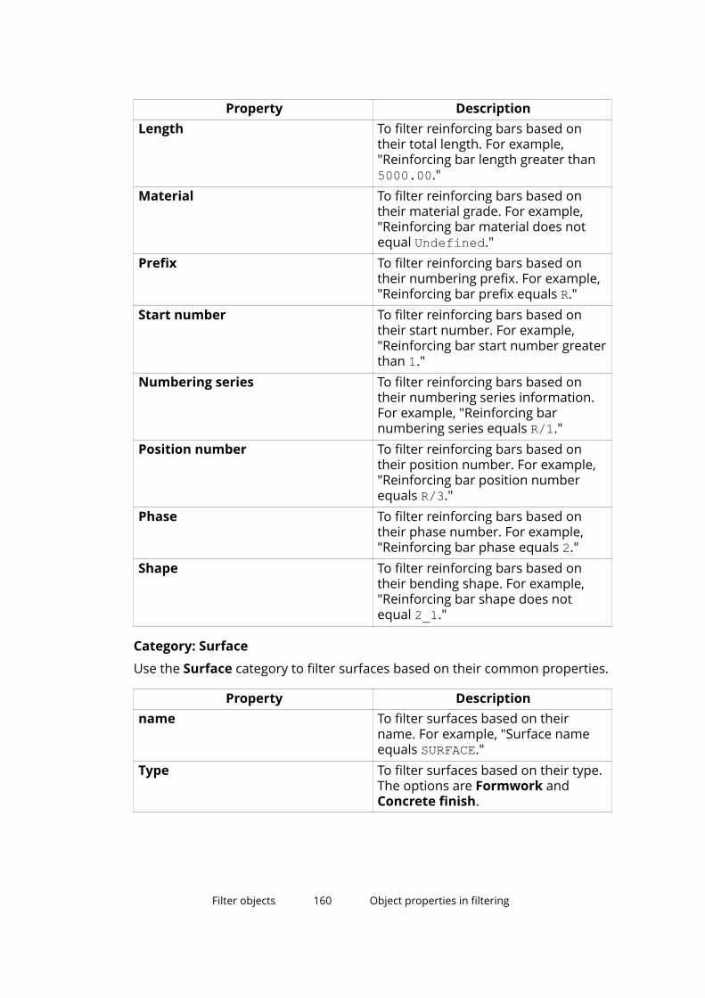
Property DescriptionLength To filter reinforcing bars based on
their total length. For example,"Reinforcing bar length greater than5000.00."
Material To filter reinforcing bars based ontheir material grade. For example,"Reinforcing bar material does notequal Undefined."
Prefix To filter reinforcing bars based ontheir numbering prefix. For example,"Reinforcing bar prefix equals R."
Start number To filter reinforcing bars based ontheir start number. For example,"Reinforcing bar start number greaterthan 1."
Numbering series To filter reinforcing bars based ontheir numbering series information.For example, "Reinforcing barnumbering series equals R/1."
Position number To filter reinforcing bars based ontheir position number. For example,"Reinforcing bar position numberequals R/3."
Phase To filter reinforcing bars based ontheir phase number. For example,"Reinforcing bar phase equals 2."
Shape To filter reinforcing bars based ontheir bending shape. For example,"Reinforcing bar shape does notequal 2_1."
Category: Surface
Use the Surface category to filter surfaces based on their common properties.
Property Descriptionname To filter surfaces based on their
name. For example, "Surface nameequals SURFACE."
Type To filter surfaces based on their type.The options are Formwork andConcrete finish.
Filter objects 160 Object properties in filtering
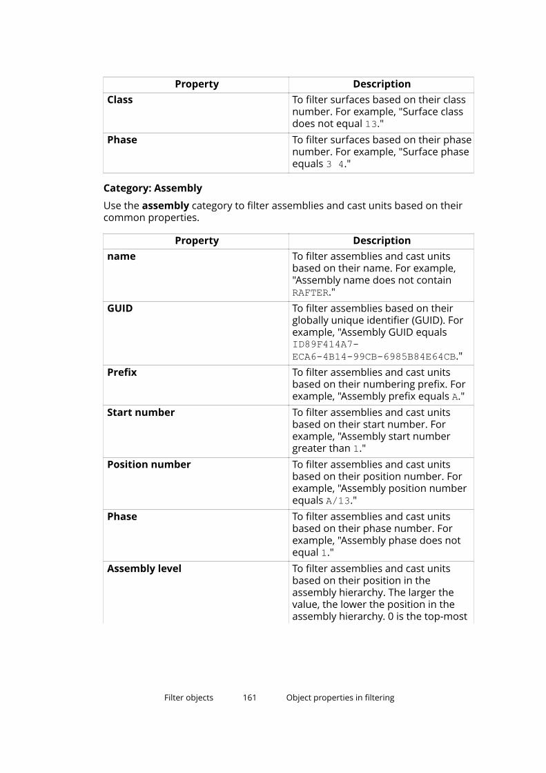
Property DescriptionClass To filter surfaces based on their class
number. For example, "Surface classdoes not equal 13."
Phase To filter surfaces based on their phasenumber. For example, "Surface phaseequals 3 4."
Category: Assembly
Use the assembly category to filter assemblies and cast units based on theircommon properties.
Property Descriptionname To filter assemblies and cast units
based on their name. For example,"Assembly name does not containRAFTER."
GUID To filter assemblies based on theirglobally unique identifier (GUID). Forexample, "Assembly GUID equalsID89F414A7-ECA6-4B14-99CB-6985B84E64CB."
Prefix To filter assemblies and cast unitsbased on their numbering prefix. Forexample, "Assembly prefix equals A."
Start number To filter assemblies and cast unitsbased on their start number. Forexample, "Assembly start numbergreater than 1."
Position number To filter assemblies and cast unitsbased on their position number. Forexample, "Assembly position numberequals A/13."
Phase To filter assemblies and cast unitsbased on their phase number. Forexample, "Assembly phase does notequal 1."
Assembly level To filter assemblies and cast unitsbased on their position in theassembly hierarchy. The larger thevalue, the lower the position in theassembly hierarchy. 0 is the top-most
Filter objects 161 Object properties in filtering
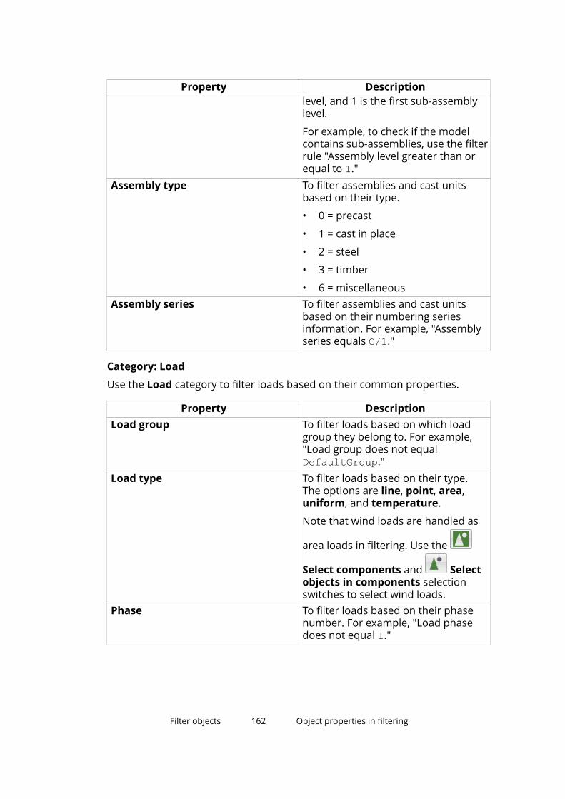
Property Descriptionlevel, and 1 is the first sub-assemblylevel.
For example, to check if the modelcontains sub-assemblies, use the filterrule "Assembly level greater than orequal to 1."
Assembly type To filter assemblies and cast unitsbased on their type.
• 0 = precast
• 1 = cast in place
• 2 = steel
• 3 = timber
• 6 = miscellaneousAssembly series To filter assemblies and cast units
based on their numbering seriesinformation. For example, "Assemblyseries equals C/1."
Category: Load
Use the Load category to filter loads based on their common properties.
Property DescriptionLoad group To filter loads based on which load
group they belong to. For example,"Load group does not equalDefaultGroup."
Load type To filter loads based on their type.The options are line, point, area,uniform, and temperature.
Note that wind loads are handled as
area loads in filtering. Use the
Select components and Selectobjects in components selectionswitches to select wind loads.
Phase To filter loads based on their phasenumber. For example, "Load phasedoes not equal 1."
Filter objects 162 Object properties in filtering
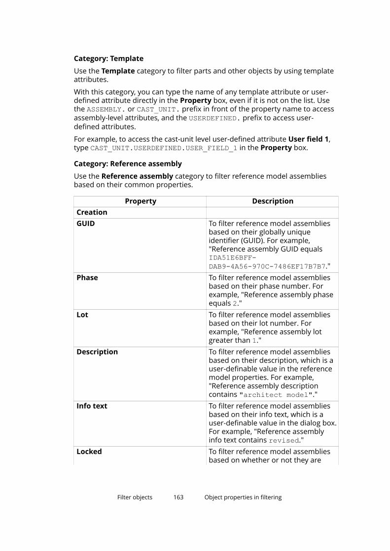
Category: Template
Use the Template category to filter parts and other objects by using templateattributes.
With this category, you can type the name of any template attribute or user-defined attribute directly in the Property box, even if it is not on the list. Usethe ASSEMBLY. or CAST_UNIT. prefix in front of the property name to accessassembly-level attributes, and the USERDEFINED. prefix to access user-defined attributes.
For example, to access the cast-unit level user-defined attribute User field 1,type CAST_UNIT.USERDEFINED.USER_FIELD_1 in the Property box.
Category: Reference assembly
Use the Reference assembly category to filter reference model assembliesbased on their common properties.
Property DescriptionCreation GUID To filter reference model assemblies
based on their globally uniqueidentifier (GUID). For example,"Reference assembly GUID equalsIDA51E6BFF-DAB9-4A56-970C-7486EF17B7B7."
Phase To filter reference model assembliesbased on their phase number. Forexample, "Reference assembly phaseequals 2."
Lot To filter reference model assembliesbased on their lot number. Forexample, "Reference assembly lotgreater than 1."
Description To filter reference model assembliesbased on their description, which is auser-definable value in the referencemodel properties. For example,"Reference assembly descriptioncontains "architect model"."
Info text To filter reference model assembliesbased on their info text, which is auser-definable value in the dialog box.For example, "Reference assemblyinfo text contains revised."
Locked To filter reference model assembliesbased on whether or not they are
Filter objects 163 Object properties in filtering
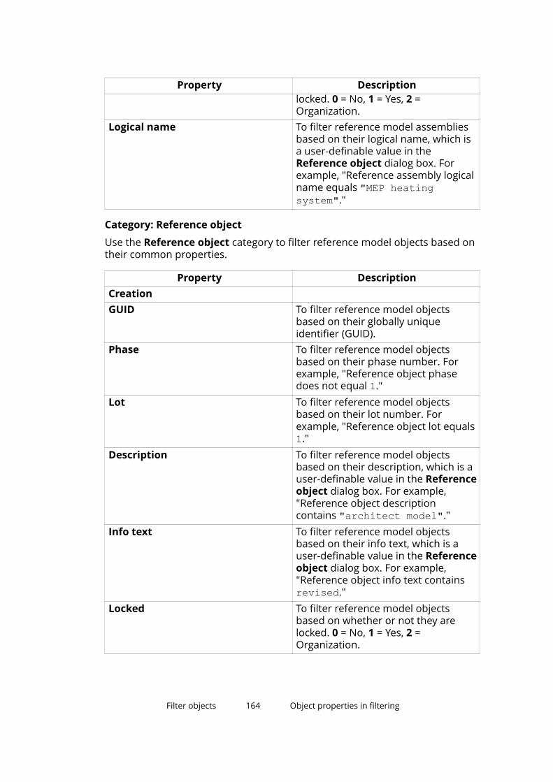
Property Descriptionlocked. 0 = No, 1 = Yes, 2 =Organization.
Logical name To filter reference model assembliesbased on their logical name, which isa user-definable value in theReference object dialog box. Forexample, "Reference assembly logicalname equals "MEP heatingsystem"."
Category: Reference object
Use the Reference object category to filter reference model objects based ontheir common properties.
Property DescriptionCreation GUID To filter reference model objects
based on their globally uniqueidentifier (GUID).
Phase To filter reference model objectsbased on their phase number. Forexample, "Reference object phasedoes not equal 1."
Lot To filter reference model objectsbased on their lot number. Forexample, "Reference object lot equals1."
Description To filter reference model objectsbased on their description, which is auser-definable value in the Referenceobject dialog box. For example,"Reference object descriptioncontains "architect model"."
Info text To filter reference model objectsbased on their info text, which is auser-definable value in the Referenceobject dialog box. For example,"Reference object info text containsrevised."
Locked To filter reference model objectsbased on whether or not they arelocked. 0 = No, 1 = Yes, 2 =Organization.
Filter objects 164 Object properties in filtering
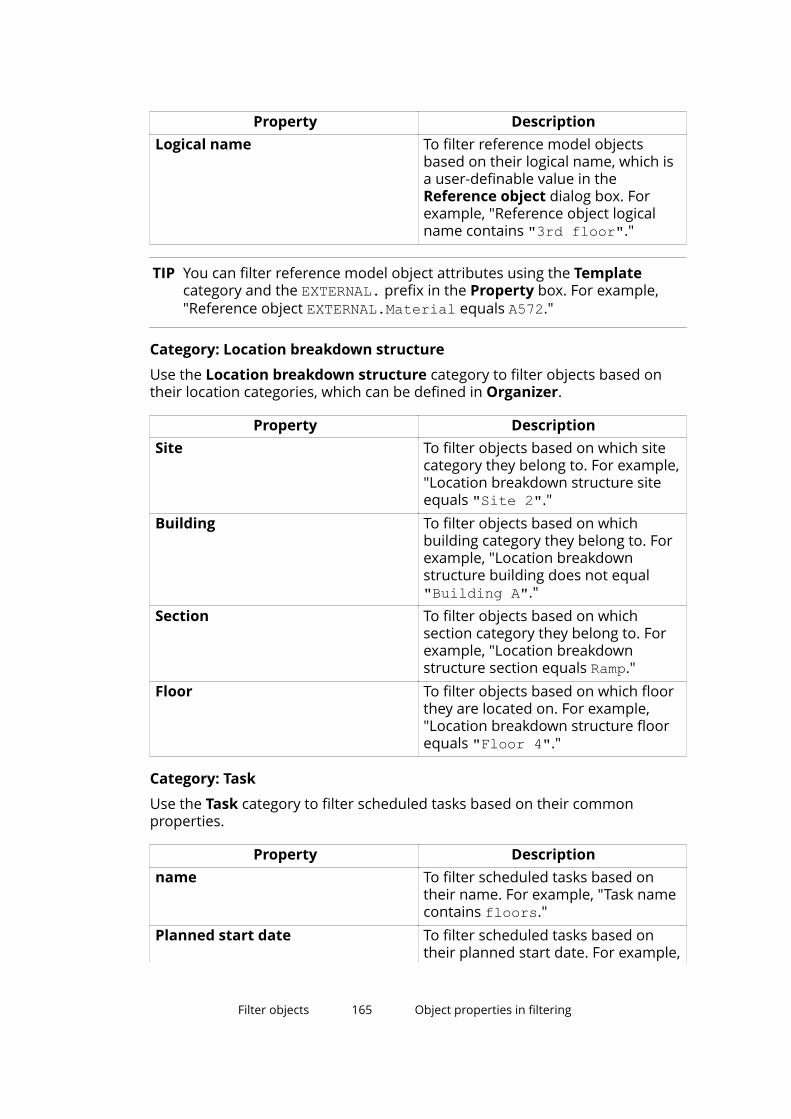
Property DescriptionLogical name To filter reference model objects
based on their logical name, which isa user-definable value in theReference object dialog box. Forexample, "Reference object logicalname contains "3rd floor"."
TIP You can filter reference model object attributes using the Templatecategory and the EXTERNAL. prefix in the Property box. For example,"Reference object EXTERNAL.Material equals A572."
Category: Location breakdown structure
Use the Location breakdown structure category to filter objects based ontheir location categories, which can be defined in Organizer.
Property DescriptionSite To filter objects based on which site
category they belong to. For example,"Location breakdown structure siteequals "Site 2"."
Building To filter objects based on whichbuilding category they belong to. Forexample, "Location breakdownstructure building does not equal"Building A"."
Section To filter objects based on whichsection category they belong to. Forexample, "Location breakdownstructure section equals Ramp."
Floor To filter objects based on which floorthey are located on. For example,"Location breakdown structure floorequals "Floor 4"."
Category: Task
Use the Task category to filter scheduled tasks based on their commonproperties.
Property Descriptionname To filter scheduled tasks based on
their name. For example, "Task namecontains floors."
Planned start date To filter scheduled tasks based ontheir planned start date. For example,
Filter objects 165 Object properties in filtering
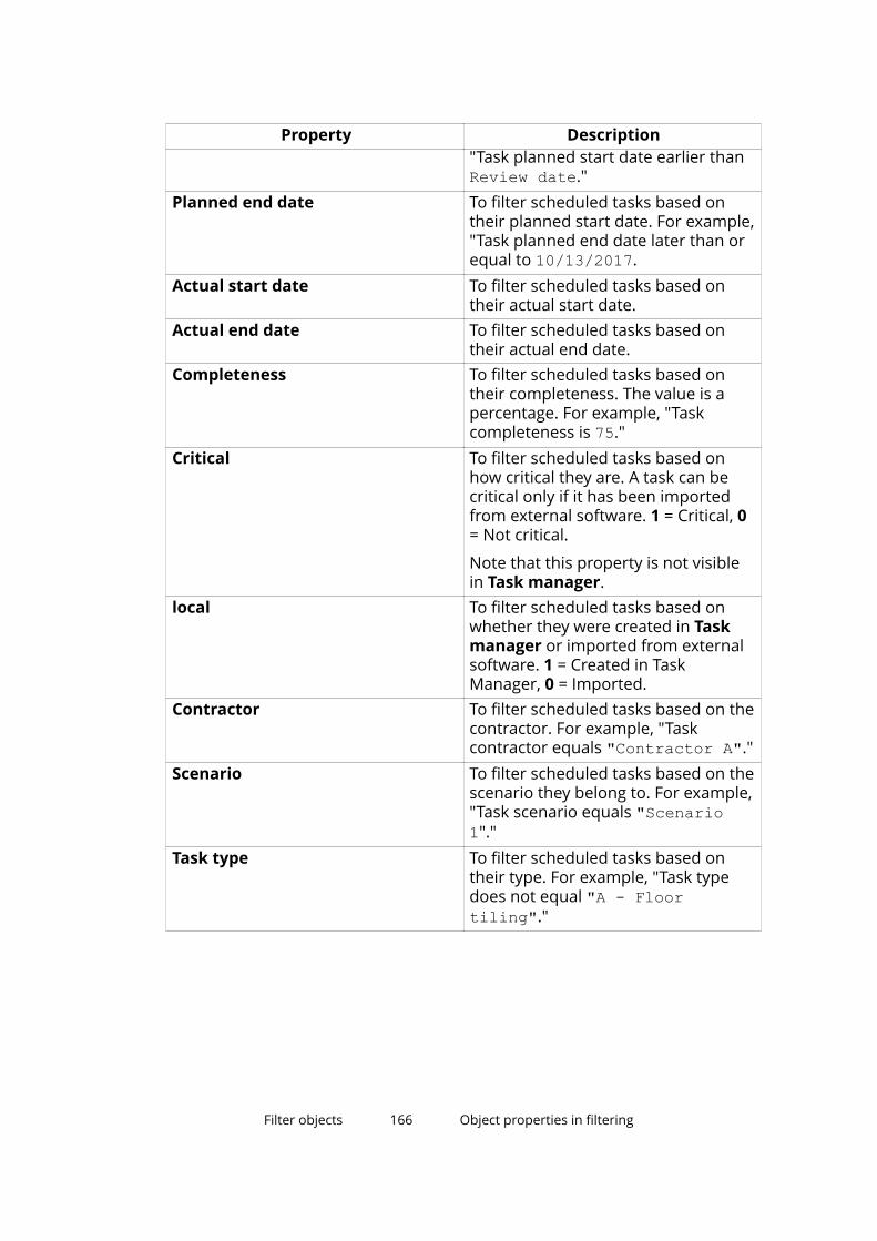
Property Description"Task planned start date earlier thanReview date."
Planned end date To filter scheduled tasks based ontheir planned start date. For example,"Task planned end date later than orequal to 10/13/2017.
Actual start date To filter scheduled tasks based ontheir actual start date.
Actual end date To filter scheduled tasks based ontheir actual end date.
Completeness To filter scheduled tasks based ontheir completeness. The value is apercentage. For example, "Taskcompleteness is 75."
Critical To filter scheduled tasks based onhow critical they are. A task can becritical only if it has been importedfrom external software. 1 = Critical, 0= Not critical.
Note that this property is not visiblein Task manager.
local To filter scheduled tasks based onwhether they were created in Taskmanager or imported from externalsoftware. 1 = Created in TaskManager, 0 = Imported.
Contractor To filter scheduled tasks based on thecontractor. For example, "Taskcontractor equals "Contractor A"."
Scenario To filter scheduled tasks based on thescenario they belong to. For example,"Task scenario equals "Scenario1"."
Task type To filter scheduled tasks based ontheir type. For example, "Task typedoes not equal "A - Floortiling"."
Filter objects 166 Object properties in filtering
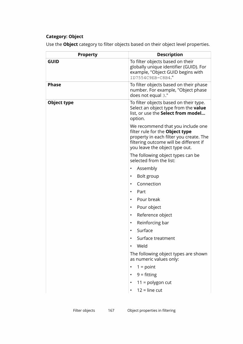
Category: Object
Use the Object category to filter objects based on their object level properties.
Property DescriptionGUID To filter objects based on their
globally unique identifier (GUID). Forexample, "Object GUID begins withID7554C9EB-C8B4."
Phase To filter objects based on their phasenumber. For example, "Object phasedoes not equal 3."
Object type To filter objects based on their type.Select an object type from the valuelist, or use the Select from model...option.
We recommend that you include onefilter rule for the Object typeproperty in each filter you create. Thefiltering outcome will be different ifyou leave the object type out.
The following object types can beselected from the list:
• Assembly
• Bolt group
• Connection
• Part
• Pour break
• Pour object
• Reference object
• Reinforcing bar
• Surface
• Surface treatment
• Weld
The following object types are shownas numeric values only:
• 1 = point
• 9 = fitting
• 11 = polygon cut
• 12 = line cut
Filter objects 167 Object properties in filtering
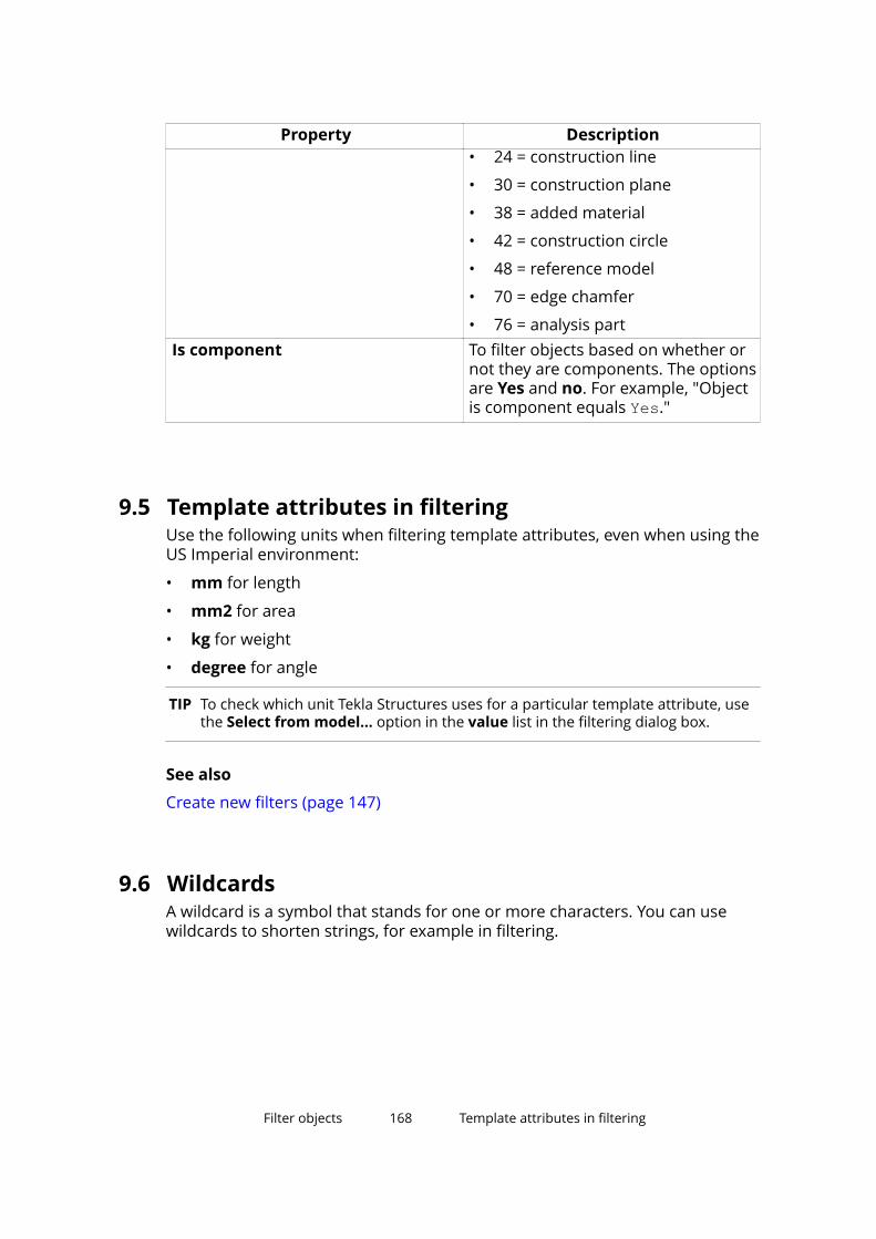
Property Description• 24 = construction line
• 30 = construction plane
• 38 = added material
• 42 = construction circle
• 48 = reference model
• 70 = edge chamfer
• 76 = analysis partIs component To filter objects based on whether or
not they are components. The optionsare Yes and no. For example, "Objectis component equals Yes."
9.5 Template attributes in filteringUse the following units when filtering template attributes, even when using theUS Imperial environment:
• mm for length
• mm2 for area
• kg for weight
• degree for angle
TIP To check which unit Tekla Structures uses for a particular template attribute, usethe Select from model... option in the value list in the filtering dialog box.
See also
Create new filters (page 147)
9.6 WildcardsA wildcard is a symbol that stands for one or more characters. You can usewildcards to shorten strings, for example in filtering.
Filter objects 168 Template attributes in filtering
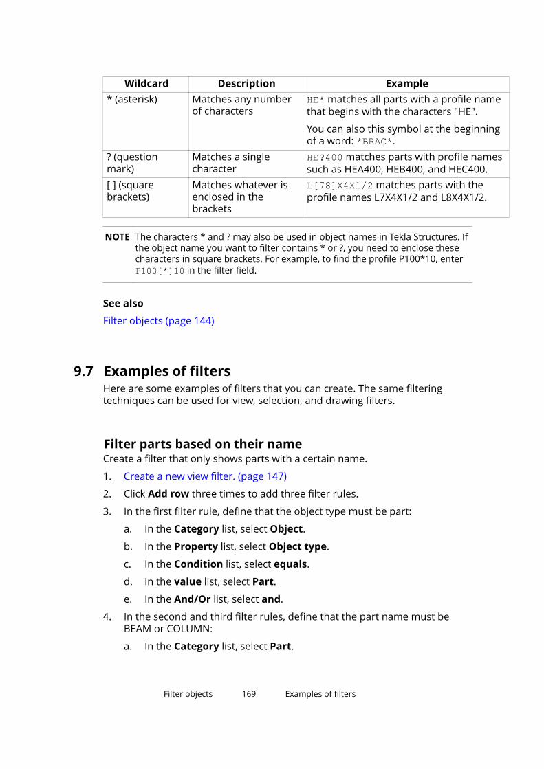
Wildcard Description Example* (asterisk) Matches any number
of charactersHE* matches all parts with a profile namethat begins with the characters "HE".
You can also this symbol at the beginningof a word: *BRAC*.
? (questionmark)
Matches a singlecharacter
HE?400 matches parts with profile namessuch as HEA400, HEB400, and HEC400.
[ ] (squarebrackets)
Matches whatever isenclosed in thebrackets
L[78]X4X1/2 matches parts with theprofile names L7X4X1/2 and L8X4X1/2.
NOTE The characters * and ? may also be used in object names in Tekla Structures. Ifthe object name you want to filter contains * or ?, you need to enclose thesecharacters in square brackets. For example, to find the profile P100*10, enter P100[*]10 in the filter field.
See also
Filter objects (page 144)
9.7 Examples of filtersHere are some examples of filters that you can create. The same filteringtechniques can be used for view, selection, and drawing filters.
Filter parts based on their nameCreate a filter that only shows parts with a certain name.
1. Create a new view filter. (page 147)
2. Click Add row three times to add three filter rules.
3. In the first filter rule, define that the object type must be part:
a. In the Category list, select Object.
b. In the Property list, select Object type.
c. In the Condition list, select equals.
d. In the value list, select Part.
e. In the And/Or list, select and.
4. In the second and third filter rules, define that the part name must beBEAM or COLUMN:
a. In the Category list, select Part.
Filter objects 169 Examples of filters
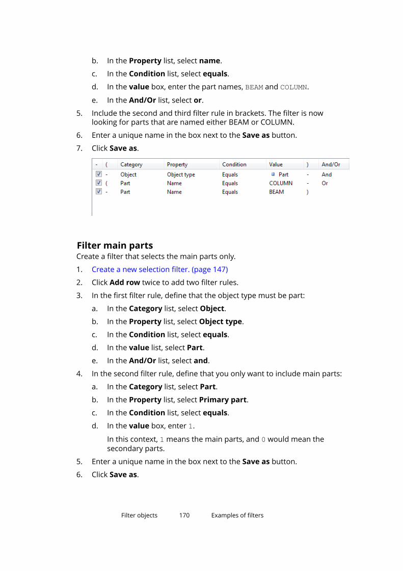
b. In the Property list, select name.
c. In the Condition list, select equals.
d. In the value box, enter the part names, BEAM and COLUMN.
e. In the And/Or list, select or.
5. Include the second and third filter rule in brackets. The filter is nowlooking for parts that are named either BEAM or COLUMN.
6. Enter a unique name in the box next to the Save as button.
7. Click Save as.
Filter main partsCreate a filter that selects the main parts only.
1. Create a new selection filter. (page 147)
2. Click Add row twice to add two filter rules.
3. In the first filter rule, define that the object type must be part:
a. In the Category list, select Object.
b. In the Property list, select Object type.
c. In the Condition list, select equals.
d. In the value list, select Part.
e. In the And/Or list, select and.
4. In the second filter rule, define that you only want to include main parts:
a. In the Category list, select Part.
b. In the Property list, select Primary part.
c. In the Condition list, select equals.
d. In the value box, enter 1.
In this context, 1 means the main parts, and 0 would mean thesecondary parts.
5. Enter a unique name in the box next to the Save as button.
6. Click Save as.
Filter objects 170 Examples of filters
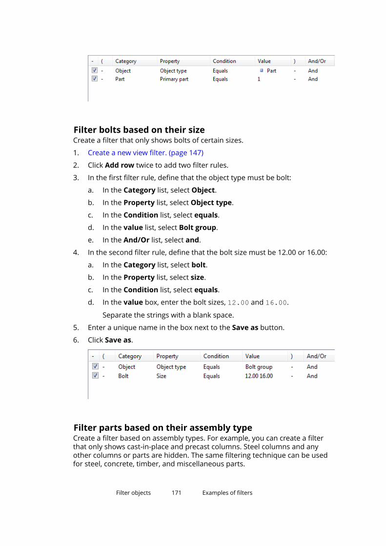
Filter bolts based on their sizeCreate a filter that only shows bolts of certain sizes.
1. Create a new view filter. (page 147)
2. Click Add row twice to add two filter rules.
3. In the first filter rule, define that the object type must be bolt:
a. In the Category list, select Object.
b. In the Property list, select Object type.
c. In the Condition list, select equals.
d. In the value list, select Bolt group.
e. In the And/Or list, select and.
4. In the second filter rule, define that the bolt size must be 12.00 or 16.00:
a. In the Category list, select bolt.
b. In the Property list, select size.
c. In the Condition list, select equals.
d. In the value box, enter the bolt sizes, 12.00 and 16.00.
Separate the strings with a blank space.
5. Enter a unique name in the box next to the Save as button.
6. Click Save as.
Filter parts based on their assembly typeCreate a filter based on assembly types. For example, you can create a filterthat only shows cast-in-place and precast columns. Steel columns and anyother columns or parts are hidden. The same filtering technique can be usedfor steel, concrete, timber, and miscellaneous parts.
Filter objects 171 Examples of filters
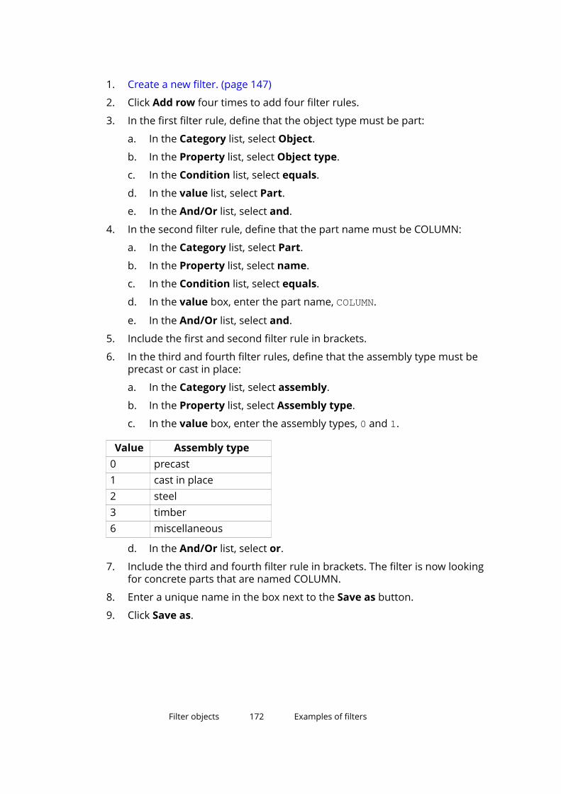
1. Create a new filter. (page 147)
2. Click Add row four times to add four filter rules.
3. In the first filter rule, define that the object type must be part:
a. In the Category list, select Object.
b. In the Property list, select Object type.
c. In the Condition list, select equals.
d. In the value list, select Part.
e. In the And/Or list, select and.
4. In the second filter rule, define that the part name must be COLUMN:
a. In the Category list, select Part.
b. In the Property list, select name.
c. In the Condition list, select equals.
d. In the value box, enter the part name, COLUMN.
e. In the And/Or list, select and.
5. Include the first and second filter rule in brackets.
6. In the third and fourth filter rules, define that the assembly type must beprecast or cast in place:
a. In the Category list, select assembly.
b. In the Property list, select Assembly type.
c. In the value box, enter the assembly types, 0 and 1.
Value Assembly type0 precast1 cast in place2 steel3 timber6 miscellaneous
d. In the And/Or list, select or.
7. Include the third and fourth filter rule in brackets. The filter is now lookingfor concrete parts that are named COLUMN.
8. Enter a unique name in the box next to the Save as button.
9. Click Save as.
Filter objects 172 Examples of filters
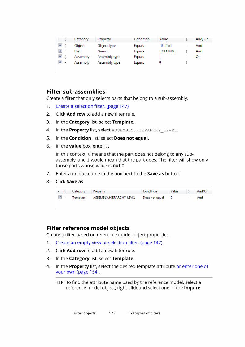
Filter sub-assembliesCreate a filter that only selects parts that belong to a sub-assembly.
1. Create a selection filter. (page 147)
2. Click Add row to add a new filter rule.
3. In the Category list, select Template.
4. In the Property list, select ASSEMBLY.HIERARCHY_LEVEL.
5. In the Condition list, select Does not equal.
6. In the value box, enter 0.
In this context, 0 means that the part does not belong to any sub-assembly, and 1 would mean that the part does. The filter will show onlythose parts whose value is not 0.
7. Enter a unique name in the box next to the Save as button.
8. Click Save as.
Filter reference model objectsCreate a filter based on reference model object properties.
1. Create an empty view or selection filter. (page 147)
2. Click Add row to add a new filter rule.
3. In the Category list, select Template.
4. In the Property list, select the desired template attribute or enter one ofyour own (page 154).
TIP To find the attribute name used by the reference model, select areference model object, right-click and select one of the Inquire
Filter objects 173 Examples of filters
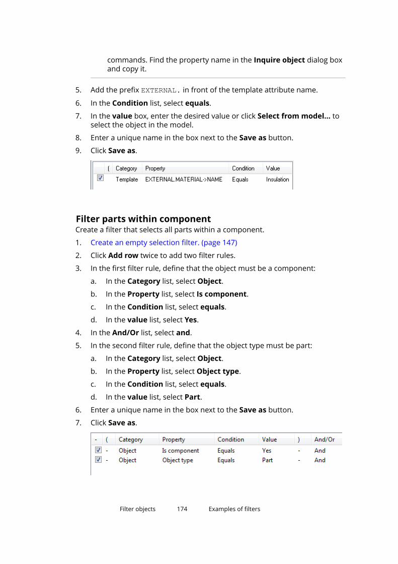
commands. Find the property name in the Inquire object dialog boxand copy it.
5. Add the prefix EXTERNAL. in front of the template attribute name.
6. In the Condition list, select equals.
7. In the value box, enter the desired value or click Select from model... toselect the object in the model.
8. Enter a unique name in the box next to the Save as button.
9. Click Save as.
Filter parts within componentCreate a filter that selects all parts within a component.
1. Create an empty selection filter. (page 147)
2. Click Add row twice to add two filter rules.
3. In the first filter rule, define that the object must be a component:
a. In the Category list, select Object.
b. In the Property list, select Is component.
c. In the Condition list, select equals.
d. In the value list, select Yes.
4. In the And/Or list, select and.
5. In the second filter rule, define that the object type must be part:
a. In the Category list, select Object.
b. In the Property list, select Object type.
c. In the Condition list, select equals.
d. In the value list, select Part.
6. Enter a unique name in the box next to the Save as button.
7. Click Save as.
Filter objects 174 Examples of filters
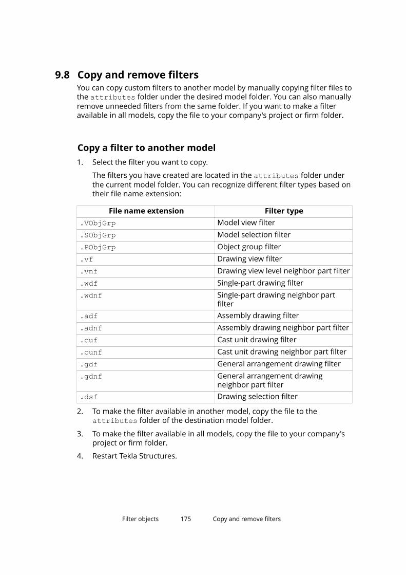
9.8 Copy and remove filtersYou can copy custom filters to another model by manually copying filter files tothe attributes folder under the desired model folder. You can also manuallyremove unneeded filters from the same folder. If you want to make a filteravailable in all models, copy the file to your company's project or firm folder.
Copy a filter to another model1. Select the filter you want to copy.
The filters you have created are located in the attributes folder underthe current model folder. You can recognize different filter types based ontheir file name extension:
File name extension Filter type.VObjGrp Model view filter.SObjGrp Model selection filter.PObjGrp Object group filter.vf Drawing view filter.vnf Drawing view level neighbor part filter.wdf Single-part drawing filter.wdnf Single-part drawing neighbor part
filter.adf Assembly drawing filter.adnf Assembly drawing neighbor part filter.cuf Cast unit drawing filter.cunf Cast unit drawing neighbor part filter.gdf General arrangement drawing filter.gdnf General arrangement drawing
neighbor part filter.dsf Drawing selection filter
2. To make the filter available in another model, copy the file to theattributes folder of the destination model folder.
3. To make the filter available in all models, copy the file to your company'sproject or firm folder.
4. Restart Tekla Structures.
Filter objects 175 Copy and remove filters
Remove a filter1. Remove the filter file from the model’s attributes folder.
2. Restart Tekla Structures.
Filter objects 176 Copy and remove filters
10 Take screenshots
A screenshot is an image of a model or drawing view. You can use screenshotsin posters, brochures, or other material to show projects carried out usingTekla Structures.
By default, the screenshots are saved in the \screenshots folder under thecurrent model folder with the name snap_xx.png.
10.1 Take a screenshot of a modelYou can take screenshots of model views.
1. Open a model and adjust the model view according to your needs.
For example, hide the work area box (page 64) if you do not want to showit.
2. On the View tab, click Screenshot --> Screenshot.
3. If you have multiple views of the model, click Pick view and select theview to take the screenshot from.
4. To modify the settings, click Options.
a. Define the width, height, and DPI of the screenshot.
b. Click OK to save the changes.
5. Define a name and location for the screenshot.
a. Select Print to file and enter a descriptive name for the screenshot inthe File name box.
You can also change the whole path. If you do not want to do this, youcan keep the default values for the path and the file name.
6. Click Show with associated viewer to show the screenshot in anapplication that is by default associated with this file type.
7. Click Capture.
Take screenshots 177 Take a screenshot of a model
10.2 Take a screenshot of a drawingA drawing screenshot is an image of an open drawing with or without borders.
1. Open a drawing and adjust the drawing view according to your needs.
For example, delete unnecessary marks or dimensions, and hideunnecessary parts.
2. On the Views tab, click Screenshot --> Screenshot.
3. Do one of the following:
• Select View to take a screenshot of the open drawing with windowborders
• Select View without borders to take a screenshot of the open drawingwithout window borders.
4. Under the preselected Print to file option enter a descriptive name forthe screenshot in the File name box.
You can also change the whole path. If you do not want to do this, you cankeep the default values for the path and the file name.
5. Click Show with associated viewer to show the screenshot in anapplication that is by default associated with this file type.
6. Click Capture.
10.3 Save a screenshot in bitmap formatBy default, screenshots are created as Portable Network Graphics (.png) files.You can also save a screenshot in bitmap (.bmp) format to use it, for example,as a custom component thumbnail.
1. On the Views tab, click Screenshot --> Screenshot.
2. Select Place on clipboard.
3. Click Capture.
4. Paste the screenshot in your graphics editor and save it in .bmp format.
NOTE The software that you use to open the screenshot may have a limit for thenumber of pixels.
Take screenshots 178 Take a screenshot of a drawing
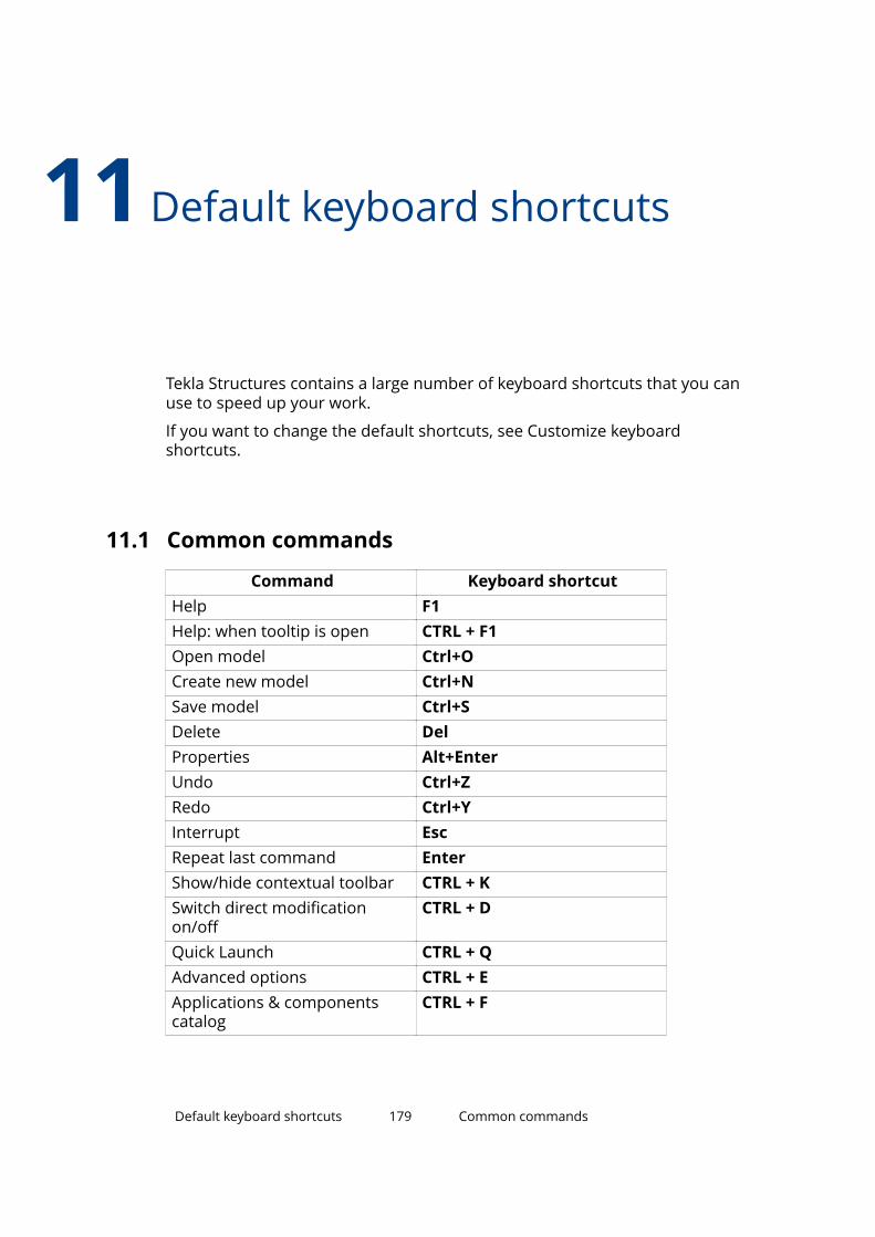
11Default keyboard shortcuts
Tekla Structures contains a large number of keyboard shortcuts that you canuse to speed up your work.
If you want to change the default shortcuts, see Customize keyboardshortcuts.
11.1 Common commands
Command Keyboard shortcutHelp F1Help: when tooltip is open CTRL + F1Open model Ctrl+OCreate new model Ctrl+NSave model Ctrl+SDelete DelProperties Alt+EnterUndo Ctrl+ZRedo Ctrl+YInterrupt EscRepeat last command EnterShow/hide contextual toolbar CTRL + KSwitch direct modificationon/off
CTRL + D
Quick Launch CTRL + QAdvanced options CTRL + EApplications & componentscatalog
CTRL + F
Default keyboard shortcuts 179 Common commands
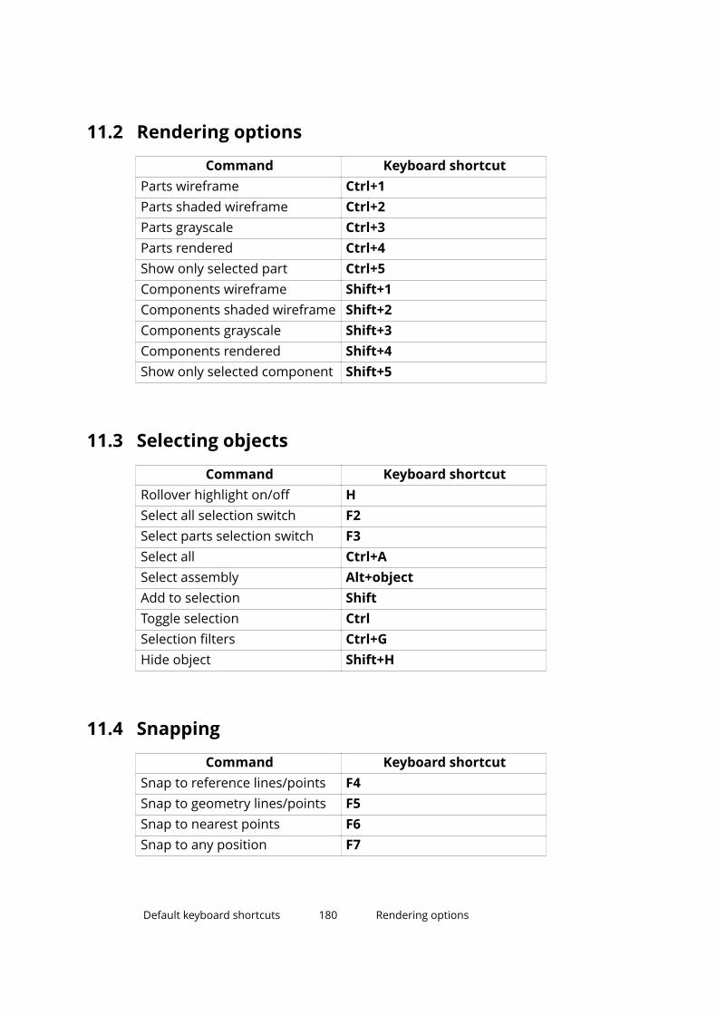
11.2 Rendering options
Command Keyboard shortcutParts wireframe Ctrl+1Parts shaded wireframe Ctrl+2Parts grayscale Ctrl+3Parts rendered Ctrl+4Show only selected part Ctrl+5Components wireframe Shift+1Components shaded wireframe Shift+2Components grayscale Shift+3Components rendered Shift+4Show only selected component Shift+5
11.3 Selecting objects
Command Keyboard shortcutRollover highlight on/off HSelect all selection switch F2Select parts selection switch F3Select all Ctrl+ASelect assembly Alt+objectAdd to selection ShiftToggle selection CtrlSelection filters Ctrl+GHide object Shift+H
11.4 Snapping
Command Keyboard shortcutSnap to reference lines/points F4Snap to geometry lines/points F5Snap to nearest points F6Snap to any position F7
Default keyboard shortcuts 180 Rendering options
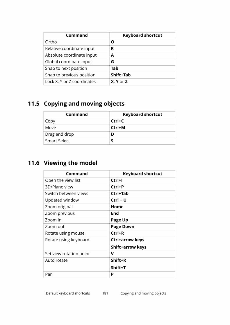
Command Keyboard shortcutOrtho ORelative coordinate input RAbsolute coordinate input AGlobal coordinate input GSnap to next position TabSnap to previous position Shift+TabLock X, Y or Z coordinates X, Y or Z
11.5 Copying and moving objects
Command Keyboard shortcutCopy Ctrl+CMove Ctrl+MDrag and drop DSmart Select S
11.6 Viewing the model
Command Keyboard shortcutOpen the view list Ctrl+I3D/Plane view Ctrl+PSwitch between views Ctrl+TabUpdated window Ctrl + UZoom original HomeZoom previous EndZoom in Page UpZoom out Page DownRotate using mouse Ctrl+RRotate using keyboard Ctrl+arrow keys
Shift+arrow keysSet view rotation point VAuto rotate Shift+R
Shift+TPan P
Default keyboard shortcuts 181 Copying and moving objects
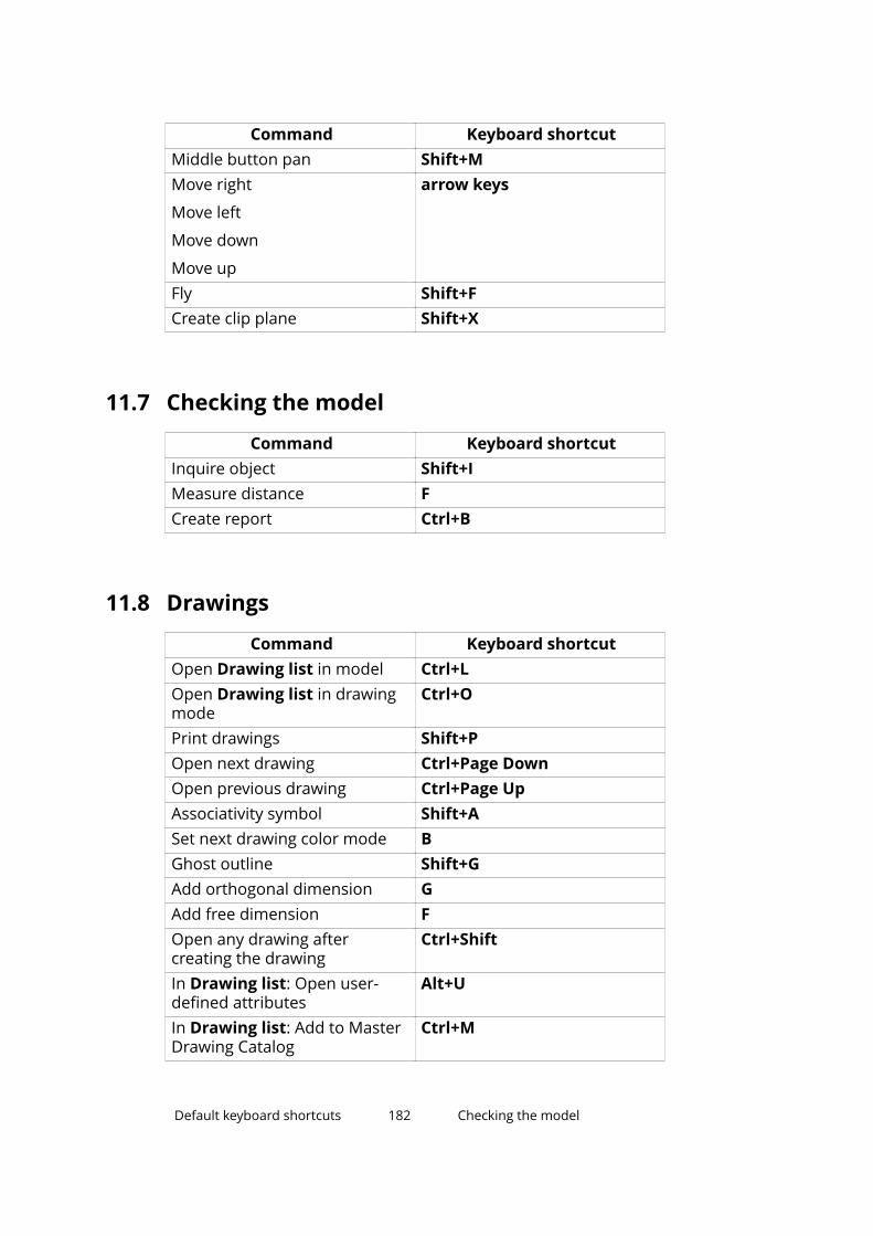
Command Keyboard shortcutMiddle button pan Shift+MMove right
Move left
Move down
Move up
arrow keys
Fly Shift+FCreate clip plane Shift+X
11.7 Checking the model
Command Keyboard shortcutInquire object Shift+IMeasure distance FCreate report Ctrl+B
11.8 Drawings
Command Keyboard shortcutOpen Drawing list in model Ctrl+LOpen Drawing list in drawingmode
Ctrl+O
Print drawings Shift+POpen next drawing Ctrl+Page DownOpen previous drawing Ctrl+Page UpAssociativity symbol Shift+ASet next drawing color mode BGhost outline Shift+GAdd orthogonal dimension GAdd free dimension FOpen any drawing aftercreating the drawing
Ctrl+Shift
In Drawing list: Open user-defined attributes
Alt+U
In Drawing list: Add to MasterDrawing Catalog
Ctrl+M
Default keyboard shortcuts 182 Checking the model
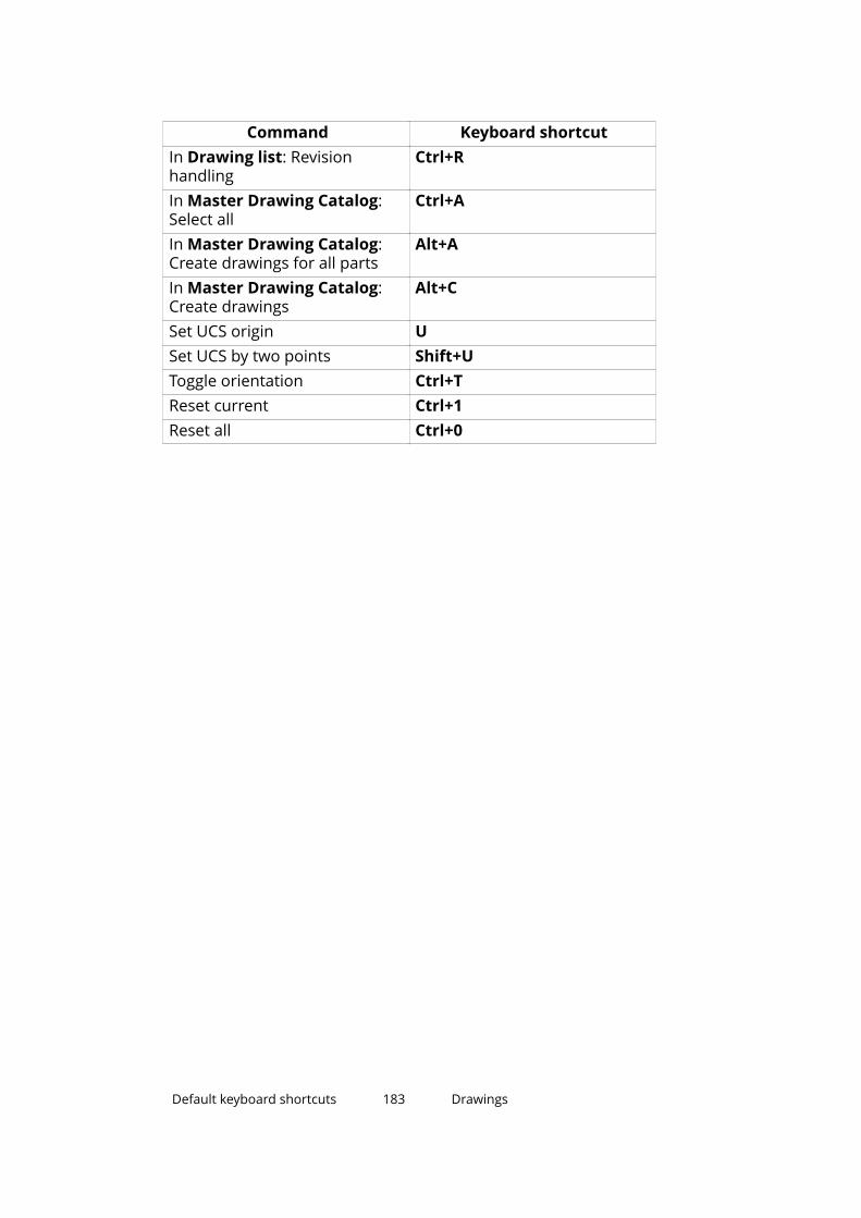
Command Keyboard shortcutIn Drawing list: Revisionhandling
Ctrl+R
In Master Drawing Catalog:Select all
Ctrl+A
In Master Drawing Catalog:Create drawings for all parts
Alt+A
In Master Drawing Catalog:Create drawings
Alt+C
Set UCS origin USet UCS by two points Shift+UToggle orientation Ctrl+TReset current Ctrl+1Reset all Ctrl+0
Default keyboard shortcuts 183 Drawings
12 Tips for basic tasks
Here we provide useful hints and tips that help you use the Tekla Structuresuser interface and its basic features more efficiently.
• Switch rollover highlight on or off (page 185)
By default, Tekla Structures highlights the objects in yellow, so that you caneasily see which objects you can select. You can switch the highlighting onor off.
• Select values from the model (page 185)
You can select object properties and dates directly from the model. Thiscan be useful when creating view filters, selection filters, and object groups.
• Interrupt object selection (page 186)
You can have Tekla Structures interrupt the object selection process if theselection takes over a defined period of time. For example, if you areworking on a large model and you accidentally select all or part of themodel, you can interrupt the selection if it takes over 5000 milliseconds (5seconds) to complete.
• Select on right-click (page 187)
You can change the settings so that you can select objects also with theright mouse button.
• Copy and move efficiently (page 187)
You can keep the Move and Copy dialog boxes open if you are going to usethem often, for example when creating grids and levels in a new model.
• Change a property in several parts at the same time (page 187)
You can quickly change a property in multiple parts simultaneously.
• Show or hide "Do not show this message again" (page 188)
Sometimes when Tekla Structures displays warning messages, you havethe option to hide future warnings of the same type. You can have TeklaStructures show these warnings again.
Tips for basic tasks 184 Drawings
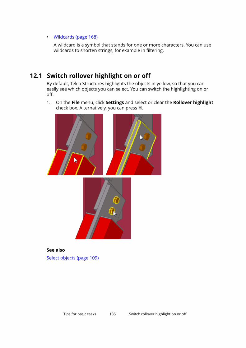
• Wildcards (page 168)
A wildcard is a symbol that stands for one or more characters. You can usewildcards to shorten strings, for example in filtering.
12.1 Switch rollover highlight on or offBy default, Tekla Structures highlights the objects in yellow, so that you caneasily see which objects you can select. You can switch the highlighting on oroff.
1. On the File menu, click Settings and select or clear the Rollover highlightcheck box. Alternatively, you can press H.
See also
Select objects (page 109)
Tips for basic tasks 185 Switch rollover highlight on or off

12.2 Select values from the modelYou can select object properties and dates directly from the model. This can beuseful when creating view filters, selection filters, and object groups.
Before you start, create an empty view or selection filter, or an object group.
1. Create an empty view or selection filter (page 147), or an object group.
2. Click Add row.
3. Select options from the Category and Property lists.
4. In the value list, select one of the options.
The availability of options depends on your selection in the Property list.You can select dates from the model only if the property is a date.
a. To select an object property, click Select from model... and thenselect an object.
b. To select a date, click Select date... to open the Select Date dialogbox, and then select one of the options.
You can either select a date from the calendar, select the review date,or define the number of days before or after the review date. Thereview date is the same as Review date in the dialog box.
12.3 Interrupt object selectionYou can have Tekla Structures interrupt the object selection process if theselection takes over a defined period of time. For example, if you are workingon a large model and you accidentally select all or part of the model, you caninterrupt the selection if it takes over 5000 milliseconds (5 seconds) tocomplete.
1. Define the time after which Tekla Structures asks if you want to interruptobject selection.
a. On the File menu, click Settings --> Advanced Options and go to theModeling Properties category.
b. Modify the advanced option XS_OBJECT_SELECTION_CONFIRMATION.
The default value is 5000 milliseconds.
c. Click OK.
2. Select (page 109) all or part of the model.
3. When Tekla Structures asks if you want to interrupt object selection, clickcancel.
Tips for basic tasks 186 Interrupt object selection
12.4 Select on right-clickYou can change the settings so that you can select objects also with the rightmouse button.
1. On the File menu, click Settings and select the following check boxes:
• Select on right-click
• Rollover highlight
2. Right-click an object to select it. Tekla Structures highlights the object andshows the related shortcut menu.
See also
Select objects (page 109)
12.5 Copy and move efficientlyYou can keep the Move and Copy dialog boxes open if you are going to usethem often, for example when creating grids and levels in a new model.
1. Run the Copy or Move command.
2. To stop copying or moving objects, right-click and select Interrupt fromthe pop-up menu.
The dialog box remains open on the screen.
3. To continue copying or moving objects:
a. Click the dialog box to activate it.
b. Select an object.
c. Enter the values you want to use, and then click the Move or Copybutton in the dialog box.
See also
Copy objects (page 120)
Move objects (page 132)
12.6 Change a property in several parts at the same timeYou can quickly change a property in multiple parts simultaneously.
1. Double-click a part to open the properties dialog box.
Tips for basic tasks 187 Select on right-click
2. Click to clear all selections from the check boxes next to theproperties.
3. Select the check box next to the property that you want to change, forexample Class.
4. Change the value.
Leave the dialog box open.
5. Select all parts whose value you want to change.
6. Click Modify in the part properties dialog box.
7. Click cancel to close the dialog box.
See also
Create, modify, and delete objects (page 77)
12.7 How to restore missing toolbarsYou can bring back the Selecting and Snapping toolbars, if you haveaccidentally removed them.
1. Go to (page 30).
2. Enter a search term:
• Type selecting if you are looking for the Selecting toolbar.
• Type snapping if you are looking for the Snapping toolbar.
3. Select the toolbar from the list that appears. The toolbar becomes visible.
TIP If you want to restore all of the default toolbars, type Show alldefault toolbars in the Quick Launch box. Select the Show alldefault toolbars command from the list that appears.
12.8 Show or hide "Do not show this message again"Sometimes when Tekla Structures displays warning messages, you have theoption to hide future warnings of the same type. You can have Tekla Structuresshow these warnings again.
Tips for basic tasks 188 How to restore missing toolbars
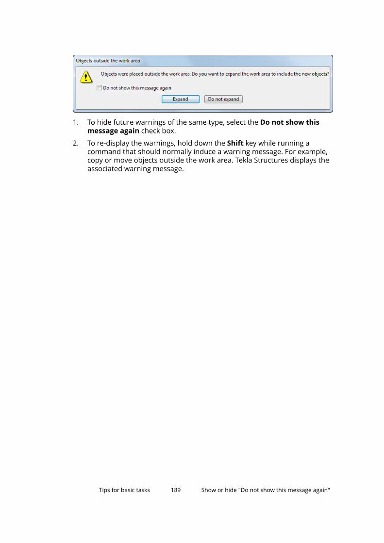
1. To hide future warnings of the same type, select the Do not show thismessage again check box.
2. To re-display the warnings, hold down the Shift key while running acommand that should normally induce a warning message. For example,copy or move objects outside the work area. Tekla Structures displays theassociated warning message.
Tips for basic tasks 189 Show or hide "Do not show this message again"

13Disclaimer
© 2017 Trimble Solutions Corporation and its licensors. All rights reserved.
This Software Manual has been developed for use with the referencedSoftware. Use of the Software, and use of this Software Manual are governedby a License Agreement. Among other provisions, the License Agreement setscertain warranties for the Software and this Manual, disclaims otherwarranties, limits recoverable damages, defines permitted uses of theSoftware, and determines whether you are an authorized user of the Software.All information set forth in this manual is provided with the warranty set forthin the License Agreement. Please refer to the License Agreement for importantobligations and applicable limitations and restrictions on your rights. Trimbledoes not guarantee that the text is free of technical inaccuracies ortypographical errors. Trimble reserves the right to make changes andadditions to this manual due to changes in the software or otherwise.
In addition, this Software Manual is protected by copyright law and byinternational treaties. Unauthorized reproduction, display, modification, ordistribution of this Manual, or any portion of it, may result in severe civil andcriminal penalties, and will be prosecuted to the full extent permitted by law.
Tekla, Tekla Structures, Tekla BIMsight, BIMsight, Tekla Civil, Tedds, Solve,Fastrak and Orion are either registered trademarks or trademarks of TrimbleSolutions Corporation in the European Union, the United States, and/or othercountries. More about Trimble Solutions trademarks: http://www.tekla.com/tekla-trademarks. Trimble is a registered trademark or trademark of TrimbleInc. in the European Union, in the United States and/or other countries. Moreabout Trimble trademarks: http://www.trimble.com/trademarks.aspx. Otherproduct and company names mentioned in this Manual are or may betrademarks of their respective owners. By referring to a third-party product orbrand, Trimble does not intend to suggest an affiliation with or endorsementby such third party and disclaims any such affiliation or endorsement, exceptwhere otherwise expressly stated.
Portions of this software:
D-Cubed 2D DCM © 2010 Siemens Industry Software Limited. All rightsreserved.
Disclaimer 190 Show or hide "Do not show this message again"
EPM toolkit © 1995-2006 Jotne EPM Technology a.s., Oslo, Norway. All rightsreserved.
Open Cascade Express Mesh © 2015 OPEN CASCADE S.A.S. All rights reserved.
PolyBoolean C++ Library © 2001-2012 Complex A5 Co. Ltd. All rights reserved.
FLY SDK - CAD SDK © 2012 VisualIntegrity™. All rights reserved.
Teigha © 2002-2016 Open Design Alliance. All rights reserved.
CADhatch.com © 2017. All rights reserved.
FlexNet Publisher © 2014 Flexera Software LLC. All rights reserved.
This product contains proprietary and confidential technology, informationand creative works owned by Flexera Software LLC and its licensors, if any. Anyuse, copying, publication, distribution, display, modification, or transmission ofsuch technology in whole or in part in any form or by any means without theprior express written permission of Flexera Software LLC is strictly prohibited.Except where expressly provided by Flexera Software LLC in writing,possession of this technology shall not be construed to confer any license orrights under any Flexera Software LLC intellectual property rights, whether byestoppel, implication, or otherwise.
To see the third party open source software licenses, go to Tekla Structures,click File menu --> Help --> About Tekla Structures and then click the 3rdparty licenses option.
The elements of the software described in this Manual are protected byseveral patents and possibly pending patent applications in the United Statesand/or other countries. For more information go to page http://www.tekla.com/tekla-patents.
Disclaimer 191 Show or hide "Do not show this message again"

Disclaimer 192 Show or hide "Do not show this message again"
Index
** character................................................... 168
33D models......................................................143D
in snapping...............................................98views......................................................... 63
?? character................................................... 168
Aadding
grid lines...................................................47align to left..................................................... 32align to tab..................................................... 32aligning
objects.................................................... 103Array of objects (29)....................................131assemblies
nested assemblies................................ 116selecting.......................................... 115,116
associativity symbol......................................38asterisk......................................................... 168Auto
in snapping...............................................98automatic rotation center............................38autosave.........................................................22
Bbackground color
changing................................................... 70examples.................................................. 70
backing upmodels......................................................22
basic view auto rotation............................... 38basics.............................................................. 25basics of Tekla Structures
tips.......................................................... 184blank project..................................................11brackets........................................................168buttons
common buttons.....................................31
Ccast units
selecting................................................. 115categories
in filtering............................................... 154centered zooms.............................................38colors
changing color settings...........................70changing the background color.............70finding RGB values.................................. 70
commandsending.......................................................26re-activating............................................. 26searching.................................................. 30using......................................................... 26
componentsselecting................................................. 116
configurations............................................ 9,12contextual toolbar.........................................34coordinate system........................................ 66coordinates.................................................... 45copying
filters.......................................................175hints and tips......................................... 187
193
models......................................................22objects.............................................119,120properties.................................................86Radial array tool.................................... 128with Array of objects (29) component 131
creating3D models................................................ 14grids.......................................................... 45model templates..................................... 20models......................................................16objects...................................................... 77screenshots............................................177view filters
selection filters................................ 147views......................................................... 52
crossing selection..........................................38
Ddeleting
objects...................................................... 77views......................................................... 62
dialog boxescommon buttons.....................................31loading properties...................................88saving properties.....................................88searching.................................................. 30
direct modificationmodifying................................................. 80
DirectX rendering.......................................... 38Do not show this message again.............. 188drag & drop....................................................38drawing objects
moving....................................................132rotating...................................................138
Eenvironments............................................. 9,12examples
background colors.................................. 70drawing filters........................................169snapping in model................................ 104view and selection filters......................169
FFile menu
switches....................................................38filtering
And/Or....................................................151categories...............................................154conditions.............................................. 151copying filters........................................ 175object properties...................................154objects.................................................... 144parentheses........................................... 151removing filters..................................... 175template attributes........................151,168use for.................................................... 144view filters
selection filters................................ 147wildcards................................................ 168
filtersexamples................................................ 169selection................................................. 112
font colorchanging................................................... 70
Ggetting started............................................... 25ghost outline..................................................38global coordinate system.............................66global point of origin.................................... 66grid color........................................................ 70grid lines
adding.......................................................47deleting.....................................................50modifying................................................. 48
gridscoordinates.............................................. 45creating.....................................................45deleting.....................................................47labels................................................... 44,45line extensions.........................................44modifying................................................. 46origin.........................................................44
gridwork plane grid........................................67
194
Hhiding
dimensions............................................ 109ribbon....................................................... 33ribbon tabs...............................................32work area................................................. 64
highlightingobjects.................................................... 185
Iif you cannot select objects....................... 118images
thumbnail image of model.....................16interrupting....................................................26
object selection..................................... 186
Kkeyboard shortcuts.....................................179
Llanguages
changing the language........................... 37large icons......................................................38linear array tool...........................................126loading
saved properties......................................88local coordinate system............................... 66
Mmessage history............................................ 32middle button pan........................................ 38minimizing the ribbon.............................32,33missing toolbars..........................................188model templates
creating.....................................................20modifying................................................. 20options......................................................20
model views................................................... 50models
about 3D models.....................................14backing up................................................22
creating.....................................................16moving...................................................... 28rotating..................................................... 28saving........................................................22thumbnail image..................................... 16zooming....................................................28
modifyingmodel templates..................................... 20objects................................................. 77,80properties in many parts simultaneously.................................................................187
movingdrawing objects..................................... 132hints and tips......................................... 187models in a view......................................28objects................................ 80,119,120,132
multi-user vs single-user..............................16
Nnavigation mode........................................... 32nested assemblies...................................... 116
Oobject properties
in filtering............................................... 154objects
copying............................................119,120creating.....................................................77deleting.....................................................77filtering................................................... 144modifying................................................. 77moving..................................... 119,120,132rotating...................................................138selecting................................................. 109
openingmodels......................................................15
origin...............................................................66ortho............................................................... 38overriding snap switches........................... 104
Ppaintbrush icon............................................. 86panning.......................................................... 28
195
partsmodifying part shape..............................80modifying properties............................ 187tips.......................................................... 187
plane views.................................................... 63Plane
in snapping...............................................98printer line widths.........................................38profiles
profile names.........................................168project setup
editing project properties.......................17prompts..........................................................32properties
copying..................................................... 86project properties....................................17
property pane................................................77
Qquestion mark............................................. 168Quick Launch................................................. 30
Rradial array tool...........................................128redrawing views............................................ 63refreshing views............................................ 63removing
filters.......................................................175reshaping
objects...................................................... 80restoring
toolbars.................................................. 188RGB values..................................................... 70ribbon
changing the appearance.......................32hiding........................................................ 32minimizing.......................................... 32,33
right-clickselecting................................................. 187
roles............................................................. 9,12rollover highlight....................................38,185rotating
drawing objects..................................... 138objects.................................................... 138
Ssaving
dialog box properties..............................88models......................................................22views......................................................... 62
screenshotscreating...................................................177
searchingfor commands and dialog boxes...........30
select on right-click....................................... 38selecting
assemblies............................................. 115cast units................................................ 115dates from model..................................185interrupting object selection............... 186nested assemblies................................ 116objects.............................. 109,112,118,185objects in components......................... 116on right-click.......................................... 187unable to select objects........................118values from model................................ 185
selection filters.....................................112,147selection switches....................................... 112setting up Tekla Structures....................... 9,12
blank project............................................ 11setting up
grid............................................................ 43views......................................................... 43work area................................................. 43work plane............................................... 43workspace................................................ 43
settingsmodel templates..................................... 20snapping.................................................107units and decimals.................................. 43
shapemodifying part shape..............................80
shifting the work plane.................................67shortcuts, see keyboard shortcuts............179showing
dimensions............................................ 109toolbars.................................................. 104views......................................................... 61work area................................................. 64
side panes......................................................36single-user vs multi-user..............................16smart select................................................... 38
196
snap grid...................................................... 103snap settings............................................... 107snap switches................................................ 99
overriding...............................................104snapping
example..................................................104using coordinates..................................104
snapping toolbar...........................................98snapping
priority...................................................... 98settings................................................... 107snap depth............................................... 98snap override.........................................104snap zone................................................. 98
snapshots, see screenshots.......................177special characters....................................... 168status bar....................................................... 32switching between
views......................................................... 63
Ttabs................................................................. 32Tekla Structures
user interface...........................................25template attributes
in filtering............................................... 168templates
model templates..................................... 20thumbnail image........................................... 16tips
copying and moving efficiently............187finding RGB values for colors.................70selecting values from model................185
toolbarscontextual toolbar...................................34how to restore....................................... 188selection switches................................. 112snapping toolbar..................................... 98
tooltips........................................................... 26tracking
along line................................................104
Uunits and decimals........................................43updating views.............................................. 63
user interface................................................ 25languages................................................. 37
Vvalues
selecting from model............................185view filters....................................................147view plane...................................................... 67view planes
moving...................................................... 52views............................................................... 50
creating.....................................................52deleting.....................................................62modifying................................................. 62naming......................................................62opening.....................................................61refreshing................................................. 63saving........................................................62switching between views........................63
Wwarning messages...................................... 188wildcards...................................................... 168work area....................................................... 64
hiding........................................................ 64work plane
shifting......................................................67show or hide............................................ 67
Zzooming in or out..........................................28
197

198