standards reference guide - anixterfile/9h0006x0_stand...2| standards reference guide for more...
TRANSCRIPT
Standards Reference Guide
Products. Technology. Services. Delivered Globally.
A Reference Guide To:
ANSI/ TIA /EIA-568-B
ANSI/ TIA /EIA-568-B.2-1
ANSI/ TIA /EIA-568-B.2-Addendum 10
ANSI/ TIA /EIA-569-B
ANSI/ TIA /EIA-606-A
J-STD-607-A
ANSI/ TIA /EIA-942
ANSI/TIA-1005
IEEE 802.3af
IEEE 802.3an
IEEE 802.11
ISO 11801, Class EA

Anixter: The Cabling System ExpertsAnixter is a leading global supplier of communications and securityproducts, electrical and electronic wire and cable, fasteners andother small components. We help our customers specify solutionsand make informed purchasing decisions around technology,applications and relevant standards. Throughout the world, we provide innovative supply chain management services to reduceour customers’ total cost of production and implementation.
Purpose of Industry StandardsBy providing guidelines for installation, maintenance and testing toimprove availability and reduce expenses associated with downtime,the telecommunications standards define cabling types, distances,connections, cable system architectures, cable terminationstandards, performance characteristics, installation and testingmethods. The standards provide recommended best practices for the design and installation of cabling systems to support a widevariety of existing and future systems to extend the life span of the telecommunications infrastructure. A single commonstructured cabling system for all communications and securitysystems simplifies moves, adds and changes, maximizes system availability and extends the usability of a cabling system. By adhering to industry standards, industrial environments can expect to fully experience the benefits of structured cabling on overall performance.
Products. Technology. Services. Delivered Globally.
Scope of this GuideThis document is meant as a reference that highlights the key points of theANSI/TIA/EIA-568-B, 569-B, 606-A, J-STD-607-A, 942, 1005 and IEEE 802.3af, IEEE 802.3an, IEEE 802.11 and ISO 11801 standards. It is not intended as a substitute for the original documents. For further information on any topic in the guide, refer to the actual standard. See the section called “ReferenceDocuments” for instructions on how to order a copy of the standard itself.
Abbreviation ReferencesANSI American National Standards InstituteASTM American Society for Testing and MaterialsCSA Canadian Standards AssociationEIA Electronic Industries AllianceIEC International Electrotechnical CommissionIEEE Institute of Electrical & Electronics EngineersISO International Organization for StandardizationNEC National Electric CodeNEMA National Electrical Manufacturers AssociationNFPA National Fire Protection AssociationTIA Telecommunications Industry Association
Standards Reference Guide |1
2| Standards Reference Guide
For more information, visit anixter.com or call 1.800.ANIXTER. Table of Contents
ANSI/TIA/EIA-568-B, Commercial BuildingTelecommunications Cabling Standard . . . . . . . . . . . . . . . . . . . . . . . . . . . . . . .3
568-B.1, General Requirements . . . . . . . . . . . . . . . . . . . . . . . . . . . . . . . . .6568-B.2, Balanced Twisted-Pair Cabling Components . . . . . . . . . . . . . . . .19568-B.2-1, Category 6 Transmission Performance . . . . . . . . . . . . . . . . . .24TIA/EIA-568-B.2- Addendum 10, Augmented Category 6 Transmission Performance . . . . . . . . . . . . . . . . . . . . . . . . . . . . . . . . . . . .30TIA/EIA-568-B.3, Optical Fiber Cabling Components . . . . . . . . . . . . . . . . .32
ANSI/TIA/EIA-569-B, Pathways and Spaces . . . . . . . . . . . . . . . . . . . . . . . . . . .34ANSI/TIA/EIA-606-A, Administration . . . . . . . . . . . . . . . . . . . . . . . . . . . . . . . .47J-STD-607-A, Grounding and Bonding . . . . . . . . . . . . . . . . . . . . . . . . . . . . . . .58ANSI/TIA/EIA-942 . . . . . . . . . . . . . . . . . . . . . . . . . . . . . . . . . . . . . . . . . . . . . . .62ANSI/TIA-1005 . . . . . . . . . . . . . . . . . . . . . . . . . . . . . . . . . . . . . . . . . . . . . . . . .7311801:2002 Standard . . . . . . . . . . . . . . . . . . . . . . . . . . . . . . . . . . . . . . . . . . .77ISO 11801, Class EA . . . . . . . . . . . . . . . . . . . . . . . . . . . . . . . . . . . . . . . . . . . .78IEEE 802.3af Power over Ethernet . . . . . . . . . . . . . . . . . . . . . . . . . . . . . . . . . .79IEEE 802.11 Wireless . . . . . . . . . . . . . . . . . . . . . . . . . . . . . . . . . . . . . . . . . . . .80IEEE 802.3an . . . . . . . . . . . . . . . . . . . . . . . . . . . . . . . . . . . . . . . . . . . . . . . . . .82The Anixter Infrastructure Solutions Lab . . . . . . . . . . . . . . . . . . . . . . . . . . . . .84Reference Documents . . . . . . . . . . . . . . . . . . . . . . . . . . . . . . . . . . . . . . . . . . .90
Products. Technology. Services. Delivered Globally.
|3Standards Reference Guide
Purpose of the ANSI/TIA/EIA-568-B StandardThe Purpose:
• Establish a generic telecommunications cabling standard that will support a multimanufacturer environment
• Enable the planning and installation of a structured cabling system for commercial buildings
• Establish performance and technical criteria for various cabling system configurations
The Standard Specifies:• Minimum requirements for telecommunications
cabling within an office environment• Recommended topologies and distances• Media parameters that determine performance• Connector and pin assignments to ensure intermateability• The useful life of telecommunications cabling systems
as being in excess of 10 years
Building telecommunications cabling specified by this standard is intended to support a wide range of different commercial building sites and applications (e.g., voice, data, text, video and image). Typically, this rangeincludes sites with a geographical extent from 10,000 to 10,000,000 sq. ft. (3,000–1,000,000 m2) of office space, and with a population of up to 50,000 individual users.
This standard replaces ANSI/TIA/EIA-568-A dated October 6, 1995. This standard also incorporates and refines the technical content of TSB67,TSB72, TSB75, TSB95 and TIA/EIA-568-A-1, A-2, A-3, A-4 and A-5.
4| Standards Reference Guide
For more information, visit anixter.com or call 1.800.ANIXTER. Section Contents
ANSI/TIA/EIA-568-BCommercial Building Telecommunications Cabling StandardTIA/EIA-568-B.1 General RequirementsThe Six Subsystems of a Structured Cabling System . . . . . . . . . . . . . . . . 6
Entrance Facilities . . . . . . . . . . . . . . . . . . . . . . . . . . . . . . . . . . . . . . . . . . . 6Equipment Room . . . . . . . . . . . . . . . . . . . . . . . . . . . . . . . . . . . . . . . . . . . . 6Backbone Cabling . . . . . . . . . . . . . . . . . . . . . . . . . . . . . . . . . . . . . . . . . . . 7Other Design Requirements . . . . . . . . . . . . . . . . . . . . . . . . . . . . . . . . . . . . 8Telecommunications Room . . . . . . . . . . . . . . . . . . . . . . . . . . . . . . . . . . . . 9Horizontal Cabling . . . . . . . . . . . . . . . . . . . . . . . . . . . . . . . . . . . . . . . . . . . 9
Specified Horizontal Cabling Topology: Star . . . . . . . . . . . . . . . . . . . . . . 9Maximum Distances for Horizontal Cabling . . . . . . . . . . . . . . . . . . . . . . . 10Multiuser Telecommunications Outlet Assembly (MUTOA) . . . . . . . . . . . . 10Consolidation Point . . . . . . . . . . . . . . . . . . . . . . . . . . . . . . . . . . . . . . . . . 11Centralized Optical Fiber Cabling . . . . . . . . . . . . . . . . . . . . . . . . . . . . . . 12Work Area . . . . . . . . . . . . . . . . . . . . . . . . . . . . . . . . . . . . . . . . . . . . . . . . 13
Work Area Components . . . . . . . . . . . . . . . . . . . . . . . . . . . . . . . . . . . 13Telecommunications Outlet . . . . . . . . . . . . . . . . . . . . . . . . . . . . . . . . 13
8-Position Modular Jack Pair Assignments for UTP . . . . . . . . . . . . . . . . . 14Channel and Permanent Link . . . . . . . . . . . . . . . . . . . . . . . . . . . . . . . . . 14Definitions of Electrical Parameters . . . . . . . . . . . . . . . . . . . . . . . . . . . . 16
TIA/EIA-568-B.2 Balanced Twisted-Pair Cabling Components . . . . . . . .19100-ohm Unshielded Twisted-Pair Cabling Systems . . . . . . . . . . . . . . . . 19Horizontal Cable . . . . . . . . . . . . . . . . . . . . . . . . . . . . . . . . . . . . . . . . . . . 19Bundled and Hybrid Cable . . . . . . . . . . . . . . . . . . . . . . . . . . . . . . . . . . . . 21UTP Connecting Hardware . . . . . . . . . . . . . . . . . . . . . . . . . . . . . . . . . . . . 21UTP Patch Cords . . . . . . . . . . . . . . . . . . . . . . . . . . . . . . . . . . . . . . . . . . . 22
Products. Technology. Services. Delivered Globally.
TIA/EIA-568-B.2-1 Balanced Twisted-Pair Cabling Components . . . . . .24Category 6 Transmission Performance . . . . . . . . . . . . . . . . . . . . . . . . . . 24Horizontal and Backbone Cabling . . . . . . . . . . . . . . . . . . . . . . . . . . . . . . 25Connecting Hardware . . . . . . . . . . . . . . . . . . . . . . . . . . . . . . . . . . . . . . . 26Assembled Patch Cords . . . . . . . . . . . . . . . . . . . . . . . . . . . . . . . . . . . . . . 27Category 6 Permanent Link . . . . . . . . . . . . . . . . . . . . . . . . . . . . . . . . . . . 28Category 6 Channel . . . . . . . . . . . . . . . . . . . . . . . . . . . . . . . . . . . . . . . . . 28Longitudinal Conversion Loss . . . . . . . . . . . . . . . . . . . . . . . . . . . . . . . . . 29
TIA/EIA-568-B.2-Addendum 10 Balanced Twisted-Pair Cabling Components (Augmented Category 6) . . . . . . . . . . . . . . . . . . . .30
Augmented Category 6 Transmission Performance . . . . . . . . . . . . . . . . . 30Augmented Category 6 Channel Requirements . . . . . . . . . . . . . . . . . . . . 31
TIA/EIA-568-B.3 Optical Fiber Cabling Components . . . . . . . . . . . . . . . .32Optical Fiber Cabling Systems . . . . . . . . . . . . . . . . . . . . . . . . . . . . . . . . . 32Optical Fiber Bend Radius . . . . . . . . . . . . . . . . . . . . . . . . . . . . . . . . . . . . 32Optical Fiber Connector . . . . . . . . . . . . . . . . . . . . . . . . . . . . . . . . . . . . . . 33Optical Fiber Telecommunications Outlet . . . . . . . . . . . . . . . . . . . . . . . . 33Optical Fiber Splices, Fusion or Mechanical . . . . . . . . . . . . . . . . . . . . . . . 33Optical Fiber Connector (mated pair) . . . . . . . . . . . . . . . . . . . . . . . . . . . . 33Patch Cords . . . . . . . . . . . . . . . . . . . . . . . . . . . . . . . . . . . . . . . . . . . . . . . 33
Standards Reference Guide |5
6| Standards Reference Guide
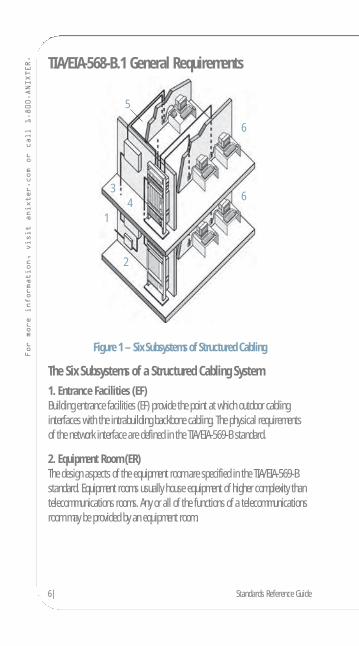
For more information, visit anixter.com or call 1.800.ANIXTER. TIA/EIA-568-B.1 General Requirements
Figure 1 – Six Subsystems of Structured Cabling
The Six Subsystems of a Structured Cabling System1. Entrance Facilities (EF)Building entrance facilities (EF) provide the point at which outdoor cablinginterfaces with the intrabuilding backbone cabling. The physical requirements of the network interface are defined in the TIA/EIA-569-B standard.
2. Equipment Room (ER)The design aspects of the equipment room are specified in the TIA/EIA-569-Bstandard. Equipment rooms usually house equipment of higher complexity thantelecommunications rooms. Any or all of the functions of a telecommunicationsroom may be provided by an equipment room.
1
2
34
5
6
6
Products. Technology. Services. Delivered Globally.
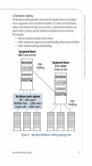
3. Backbone CablingThe backbone cabling provides interconnection between telecommunicationsrooms, equipment rooms and entrance facilities. It consists of the backbonecables, intermediate and main cross-connects, mechanical terminations andpatch cords or jumpers used for backbone-to-backbone cross-connection. This includes:
• Vertical connection between floors (risers)• Cables between an equipment room and building cable entrance facilities• Cables between buildings (interbuilding).
Figure 2 – Specified Backbone Cabling Topology: Star
Equipment RoomMain Cross-connect
Inter-building
Equipment RoomIntermediate
Cross-connect
Backbone media optionsUTP – 800 meters*
Multifiber fiber – 2,000 metersSingle-mode – 3,000 meters
Inter-building
Standards Reference Guide |7

8| Standards Reference Guide
For more information, visit anixter.com or call 1.800.ANIXTER. Other Design Requirements
• Star topology• No more than two hierarchical levels of backbone cross-connects• Bridge taps are not allowed • Main and intermediate cross-connect jumper or patch cord lengths should
not exceed 20 m (66 ft.)• Avoid installing in areas where sources of high levels of EMI/RFI may exist• Grounding should meet the requirements as defined in J-STD-607-A
Note: It is recommended that the user consult with equipment manufacturers,application standards and system providers for additional information whenplanning shared-sheath applications on UTP backbone cables.
*Note: Backbone distances are application-dependent. The maximum distancesspecified above are based on voice transmission for UTP and data transmissionover fiber. A 90 m distance applies to UTP at spectral bandwidths of 5–16 MHzfor Category 3 and 20–100 MHz for Category 5e. Current state-of-the-artdistribution facilities usually include a combination of both copper and fiberoptic cables in the backbone.
Maximum Backbone DistancesMain to Main to Intermediate
Media Horizontal Intermediate to HorizontalType Cross-Connect Cross-Connect Cross-Connect
Copper (Voice*) 800 m (2,624 ft.) 500 m (1,640 ft.) 300 m (984 ft.)Multimode 2,000 m (6,560 ft.) 1,700 m (5,575 ft.) 300 m (984 ft.)Single-mode 3,000 m (9,840 ft.) 2,700 m (8,855 ft.) 300 m (984 ft.)
Products. Technology. Services. Delivered Globally.
4. Telecommunications Room (TR)A telecommunications room is the area within a building that houses thetelecommunications cabling system equipment. This includes the mechanicalterminations and cross-connects for the horizontal and backbone cablingsystem. Please refer to TIA/EIA-569-B for the design specifications of thetelecommunications room.
5. Horizontal Cabling
Specified Horizontal Cabling Topology: StarThe horizontal cabling system extends from the work area telecommunicationsinformation outlet to the telecommunications room and consists of thefollowing:
• Horizontal cabling• Telecommunications outlet• Cable terminations• Cross-connections• Patch cords
Four media types are recognized as options for horizontal cabling, eachextending a maximum distance of 90 m:
• 4-pair, 100-ohm UTP/ScTP cable (24 AWG solid conductors)• 2-fiber, 62.5/125 µm or 50/125 µm optical cable
Standards Reference Guide |9

10| Standards Reference Guide
For more information, visit anixter.com or call 1.800.ANIXTER. Maximum Distances for Horizontal Cabling
Figure 3 – Maximum Distances for Horizontal Cabling
In addition to the 90 m of horizontal cable, a total of 10 m is allowed for workarea and telecommunications room patch and jumper cables.
Multiuser Telecommunications Outlet AssemblyOptional practices for open office environments are specified for any horizontaltelecommunications cabling recognized in TIA/EIA 568-B.
Figure 4 – Six Subsystems of Structured Cabling
A multiuser telecommunications outlet assembly (MUTOA) facilitates thetermination of multiple horizontal cables in a common location within

Products. Technology. Services. Delivered Globally.
a column, wall or permanently secured furniture cluster. Work area cables may then be routed through furniture pathways and directly connected to work area equipment. Each furniture cluster should have one MUTOA that serves a maximum of 12 work areas. Ceiling and access floor mounting is not allowed by TIA/EIA-569-B.
Note: No work area cable length may exceed 22 m (72 ft.).
For optical fiber, any combination of horizontal, work area cables, patch cordsand equipment cords may not exceed 100 m (328 ft.).
Consolidation Point
Figure 5 – Consolidation Point
A consolidation point differs from a MUTOA in that it requires an additionalconnection for each horizontal cable run. Only one consolidation point (aninterconnection point in the horizontal cabling) is allowed at a distance of at least 15 m (49 ft.) from the telecommunications room. A transition point(transition from round to flat undercarpet cable) is not allowed. A consolidationpoint is installed in unobstructed building columns, permanent walls, ceilings or access floors (if accessible).
Work Area
TelecommunicationsRoom Horizontal Cabling
Horizontalcross-connect
Backbonecable
Connectinghardware
Work areacables
Work area telecommunicationoutlet/connector or multiusertelecommunications outlet assembly
ConsolidationPoint
Maximum work area cable length is determined by the following table:Length of Maximum Maximum Combined LengthHorizontal Length of Work of Work Area Cables, PatchCable Area Cable (24AWG) Cords and Equipment Cablem (ft.) m (ft.) m (ft.)
90 (295) 5 (16) 10 (33)85 (279) 9 (30) 14 (46)80 (262) 13 (44) 18 (59)75 (246) 17 (57) 22 (72)70 (230) 22 (72) 27 (89)
Standards Reference Guide |11
12| Standards Reference Guide
For more information, visit anixter.com or call 1.800.ANIXTER. The multiuser telecommunications outlet and consolidation point methods
are intended to be mutually exclusive. Labeling and allowing for spares is required. Moves, adds and changes should be administered in thetelecommunications room.
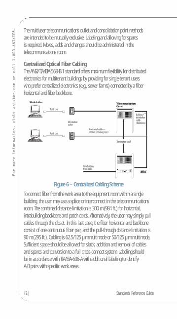
Centralized Optical Fiber CablingThe ANSI/TIA/EIA-568-B.1 standard offers maximum flexibility for distributedelectronics for multitenant buildings by providing for single-tenant users who prefer centralized electronics (e.g., server farms) connected by a fiberhorizontal and fiber backbone.
Figure 6 – Centralized Cabling Scheme
To connect fiber from the work area to the equipment room within a singlebuilding, the user may use a splice or interconnect in the telecommunicationsroom. The combined distance limitation is 300 m (984 ft.) for horizontal, intrabuilding backbone and patch cords. Alternatively, the user may simply pullcables through the closet. In this last case, the fiber horizontal and backboneconsist of one continuous fiber pair, and the pull-through distance limitation is90 m (295 ft.). Cabling is 62.5/125 µm multimode or 50/125 µm multimode.Sufficient space should be allowed for slack, addition and removal of cables and spares and conversion to a full cross-connect system. Labeling should be in accordance with TIA/EIA-606-A with additional labeling to identify A-B pairs with specific work areas.
Products. Technology. Services. Delivered Globally.
6. Work Area (WA)The work area components extend from the telecommunications (information)outlet to the station equipment. Work area wiring is designed to be relativelysimple to interconnect, so moves, adds and changes are easily managed.
Work Area Components• Station equipment – computers, data terminals, telephones, etc.• Patch cables – modular cords, PC adapter cables, fiber jumpers, etc.• Adapters – baluns, etc. (must be external to telecommunications outlet)
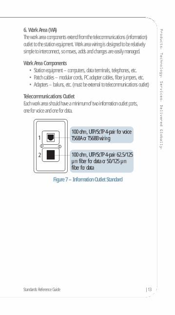
Telecommunications OutletEach work area should have a minimum of two information outlet ports, one for voice and one for data.
Figure 7 – Information Outlet Standard
100 ohm, UTP/ScTP 4-pair 62.5/125 µm fiber for data or 50/125 µm fiber for data
100 ohm, UTP/ScTP 4-pair for voice T568A or T568B wiring1
2
Standards Reference Guide |13
14| Standards Reference Guide
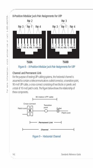
For more information, visit anixter.com or call 1.800.ANIXTER. 8-Position Modular Jack Pair Assignments for UTP
Figure 8 – 8-Position Modular Jack Pair Assignments for UTP
Channel and Permanent LinkFor the purpose of testing UTP cabling systems, the horizontal channel isassumed to contain a telecommunications outlet/connector, a transition point,90 m of UTP cable, a cross-connect consisting of two blocks or panels and a total of 10 m of patch cords. The figure below shows the relationship of these components.
Figure 9 – Horizontal Channel
Pair 2
T568A T568B
Pair 3 Pair 1 Pair 4
1 2 3 4 5 6 7 8 W-G G W-0 BL W-BL O W-BR BR
Pair 3
Pair 3 Pair 1 Pair 4
1 2 3 4 5 6 7 8 W-O O W-G BL W-BL G W-BR BR

Products. Technology. Services. Delivered Globally.
Two link configurations are defined for testing purposes. The permanent linkincludes the horizontal distribution cable, telecommunications outlet/connectoror transition point and one horizontal cross-connect component including the mated connections. This is assumed to be the permanent part of a link. The channel is comprised of the permanent link plus cross-connect equipment,user equipment cord and cross-connect patch cable.
Physical requirements of 4-pair UTP:
• Maximum diameter: 1/4 in.• Breaking strength: 90 lb.• Maximum pulling tension: 25 lb.
Minimum Bend Radius
Horizontal UTP (4-pair) 4 x diameterHorizontal ScTP 8 x diameterBackbone Cable 10 x diameterPatch Cord Not determined
Standards Reference Guide |15

16| Standards Reference Guide
For more information, visit anixter.com or call 1.800.ANIXTER. Definitions of Electrical Parameters
Insertion Loss: This term has replaced the term “attenuation” (ATTN). It is a measure of the decrease of signal strength as it travels down the media.
NEXT (near-end crosstalk): A measure of the unwanted signal coupling from a transmitter at the near-end into a neighboring (non-energized) pair measuredat the near-end.
PSNEXT (powersum near-end crosstalk): A computation of the unwantedsignal coupling from multiple transmitters at the near-end into a neighboring(non-energized) pair measured at the near-end.
FEXT (far-end crosstalk): A measure of the unwanted signal coupling from a transmitter at the near-end into a neighboring pair measured at the far-end.
ELFEXT (equal-level far-end crosstalk): A measure of the unwanted signalcoupling from a transmitter at the near-end into a neighboring pair measured at the far-end, relative to the received signal level measured on that same pair.Referred to as ACR-F (insertion loss to crosstalk ratio far-end) in the TIA/EIA-568-B.2-Addendum 10. (ELFEXT is FEXT adjusted to discount insertion loss.)
PSAACRF (powersum insertion loss to alien crosstalk ratio far-end): A computation of signal coupling from multiple pairs of disturbing channels to a disturbed pair in another channel measured at the far-end and relative to the received signal level in the disturbed pair at the far-end. Also referred to as powersum alien equal-level far-end crosstalk (PSAELFEXT).
PSANEXT (powersum alien near-end crosstalk): A computation of signalcoupling from multiple near-end disturbing channel pairs into a disturbed pairof a neighboring channel or part thereof, measured at the near-end.
PSAFEXT (powersum alien far-end crosstalk): A computation of signalcoupling from multiple near-end disturbing channel pairs into a disturbed pairof a neighboring channel or part thereof, measured at the far-end.
Products. Technology. Services. Delivered Globally.
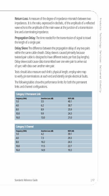
Return Loss: A measure of the degree of impedance mismatch between twoimpedances. It is the ratio, expressed in decibels, of the amplitude of a reflectedwave echo to the amplitude of the main wave at the junction of a transmissionline and a terminating impedance.
Propagation Delay: The time needed for the transmission of signal to travelthe length of a single pair.
Delay Skew: The difference between the propagation delay of any two pairswithin the same cable sheath. Delay skew is caused primarily because twisted-pair cable is designed to have different twists per foot (lay lengths).Delay skew could cause data transmitted over one wire pair to arrive out of sync with data over another wire pair.
Tests should also measure each link’s physical length, employ wire map to verify pin terminations at each end and identify simple electrical faults.
The following tables show the performance limits for both the permanent links and channel configurations.
Category 3 ChannelFrequency (MHz) Insertion Loss (dB) NEXT (dB)
1.0 4.2 39.14.0 7.3 29.38.0 10.2 24.310.0 11.5 22.716.0 14.9 19.3
Category 3 Permanent LinkFrequency (MHz) Insertion Loss (dB) NEXT (dB)
1.0 3.5 40.14.0 6.2 30.78.0 8.9 25.910.0 9.9 24.316.0 13.0 21.0
Standards Reference Guide |17
18| Standards Reference Guide
For more information, visit anixter.com or call 1.800.ANIXTER.
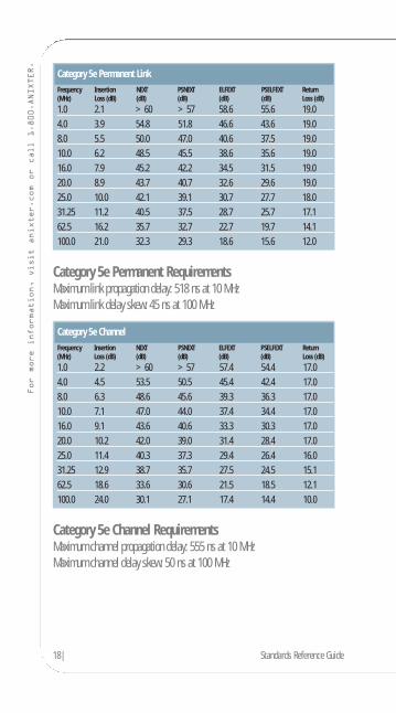
Category 5e Permanent RequirementsMaximum link propagation delay: 518 ns at 10 MHzMaximum link delay skew: 45 ns at 100 MHz
Category 5e Channel RequirementsMaximum channel propagation delay: 555 ns at 10 MHzMaximum channel delay skew: 50 ns at 100 MHz
Category 5e ChannelFrequency Insertion NEXT PSNEXT ELFEXT PSELFEXT Return(MHz) Loss (dB) (dB) (dB) (dB) (dB) Loss (dB)
1.0 2.2 >60 >57 57.4 54.4 17.04.0 4.5 53.5 50.5 45.4 42.4 17.08.0 6.3 48.6 45.6 39.3 36.3 17.010.0 7.1 47.0 44.0 37.4 34.4 17.016.0 9.1 43.6 40.6 33.3 30.3 17.020.0 10.2 42.0 39.0 31.4 28.4 17.025.0 11.4 40.3 37.3 29.4 26.4 16.031.25 12.9 38.7 35.7 27.5 24.5 15.162.5 18.6 33.6 30.6 21.5 18.5 12.1100.0 24.0 30.1 27.1 17.4 14.4 10.0
Category 5e Permanent LinkFrequency Insertion NEXT PSNEXT ELFEXT PSELFEXT Return(MHz) Loss (dB) (dB) (dB) (dB) (dB) Loss (dB)
1.0 2.1 >60 >57 58.6 55.6 19.04.0 3.9 54.8 51.8 46.6 43.6 19.08.0 5.5 50.0 47.0 40.6 37.5 19.010.0 6.2 48.5 45.5 38.6 35.6 19.016.0 7.9 45.2 42.2 34.5 31.5 19.020.0 8.9 43.7 40.7 32.6 29.6 19.025.0 10.0 42.1 39.1 30.7 27.7 18.031.25 11.2 40.5 37.5 28.7 25.7 17.162.5 16.2 35.7 32.7 22.7 19.7 14.1100.0 21.0 32.3 29.3 18.6 15.6 12.0
Products. Technology. Services. Delivered Globally.
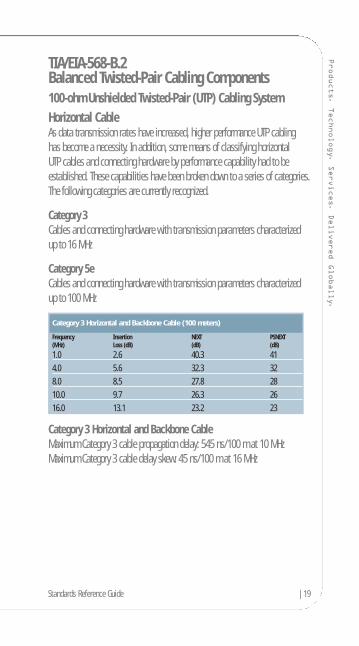
TIA/EIA-568-B.2Balanced Twisted-Pair Cabling Components100-ohm Unshielded Twisted-Pair (UTP) Cabling SystemHorizontal CableAs data transmission rates have increased, higher performance UTP cabling has become a necessity. In addition, some means of classifying horizontal UTP cables and connecting hardware by performance capability had to beestablished. These capabilities have been broken down to a series of categories.The following categories are currently recognized.
Category 3Cables and connecting hardware with transmission parameters characterized up to 16 MHz
Category 5eCables and connecting hardware with transmission parameters characterized up to 100 MHz
Category 3 Horizontal and Backbone CableMaximum Category 3 cable propagation delay: 545 ns/100 m at 10 MHzMaximum Category 3 cable delay skew: 45 ns/100 m at 16 MHz
Category 3 Horizontal and Backbone Cable (100 meters)
Frequency Insertion NEXT PSNEXT(MHz) Loss (dB) (dB) (dB)
1.0 2.6 40.3 414.0 5.6 32.3 328.0 8.5 27.8 2810.0 9.7 26.3 2616.0 13.1 23.2 23
Standards Reference Guide |19
20| Standards Reference Guide
For more information, visit anixter.com or call 1.800.ANIXTER.
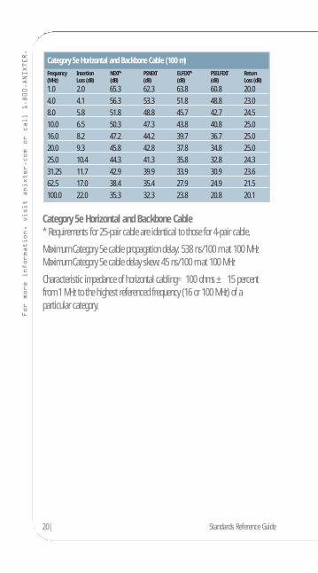
Category 5e Horizontal and Backbone Cable* Requirements for 25-pair cable are identical to those for 4-pair cable.
Maximum Category 5e cable propagation delay: 538 ns/100 m at 100 MHzMaximum Category 5e cable delay skew: 45 ns/100 m at 100 MHz
Characteristic impedance of horizontal cabling=100 ohms ± 15 percent from 1 MHz to the highest referenced frequency (16 or 100 MHz) of a particular category.
Category 5e Horizontal and Backbone Cable (100 m)Frequency Insertion NEXT* PSNEXT ELFEXT* PSELFEXT Return(MHz) Loss (dB) (dB) (dB) (dB) (dB) Loss (dB)
1.0 2.0 65.3 62.3 63.8 60.8 20.04.0 4.1 56.3 53.3 51.8 48.8 23.08.0 5.8 51.8 48.8 45.7 42.7 24.510.0 6.5 50.3 47.3 43.8 40.8 25.016.0 8.2 47.2 44.2 39.7 36.7 25.020.0 9.3 45.8 42.8 37.8 34.8 25.025.0 10.4 44.3 41.3 35.8 32.8 24.331.25 11.7 42.9 39.9 33.9 30.9 23.662.5 17.0 38.4 35.4 27.9 24.9 21.5100.0 22.0 35.3 32.3 23.8 20.8 20.1
Products. Technology. Services. Delivered Globally.
Bundled and Hybrid CableBundled, wrapped or hybrid cables are allowed for use in horizontal cabling,provided that each individual cable type meets TIA/EIA-568-B.2 specificationsand that powersum NEXT loss created by adjacent jacketed cables is 3 dB betterthan the normally allowed pair-to-pair NEXT for the cable type being tested.Color codes must follow individual cable standards to distinguish them frommultipair UTP backbone cabling.
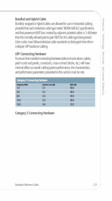
UTP Connecting HardwareTo ensure that installed connecting hardware (telecommunications outlets,patch cords and panels, connectors, cross-connect blocks, etc.) will haveminimal effect on overall cabling system performance, the characteristics and performance parameters presented in this section must be met.
Category 3 Connecting Hardware
Category 3 Connecting HardwareFrequency (MHz) Insertion Loss (dB) NEXT (dB)
1.0 0.1 58.04.0 0.2 46.08.0 0.3 39.910.0 0.3 38.016.0 0.4 33.9
Standards Reference Guide |21

22| Standards Reference Guide
For more information, visit anixter.com or call 1.800.ANIXTER.
Category 5e Connecting HardwareThe preferred termination method for all UTP connecting hardware includes the insulation displacement contact (IDC). To ensure overall system integrity,horizontal cables need to be terminated with connecting hardware of the samecategory or higher.
The following requirements apply only to wire and cable used for patch cordsand cross-connect jumpers.
UTP Patch Cords
Jumper and Patch Cord Maximum Length Limitations:• 20 m (66 ft.) in main cross-connect• 20 m (66 ft.) in intermediate cross-connect• 6 m (20 ft.) in telecommunications room• 3 m (10 ft.) in the work area
Patch Cord Cable Construction:• Stranded conductors for extended flex-life cables used for patch cords
and cross-connect jumpers need to be of the same performance category(or higher) as the horizontal cables they connect.
• UTP cabling systems are not Category 3 or 5e compliant unless allcomponents of the system satisfy their respective category requirements.
Category 5e Connecting HardwareFrequency Insertion NEXT FEXT Return(MHz) Loss (dB) (dB) (dB) Loss (dB)
1.0 0.1 65.0 65.0 30.04.0 0.1 65.0 63.1 30.08.0 0.1 64.9 57.0 30.010.0 0.1 63.0 55.1 30.020.0 0.2 57.0 49.1 30.025.0 0.2 55.0 47.1 30.031.25 0.2 53.1 45.2 30.062.5 0.3 47.1 39.2 24.1100.0 0.4 43.0 35.1 20.0
Products. Technology. Services. Delivered Globally.
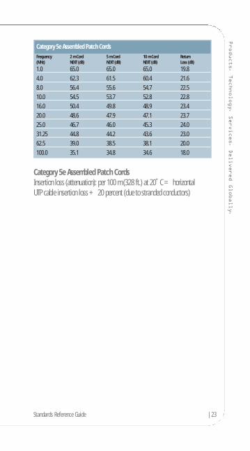
Category 5e Assembled Patch CordsInsertion loss (attenuation): per 100 m (328 ft.) at 20˚C = horizontal UTP cable insertion loss + 20 percent (due to stranded conductors)
Category 5e Assembled Patch Cords Frequency 2 m Cord 5 m Cord 10 m Cord Return(MHz) NEXT (dB) NEXT (dB) NEXT (dB) Loss (dB)
1.0 65.0 65.0 65.0 19.84.0 62.3 61.5 60.4 21.68.0 56.4 55.6 54.7 22.510.0 54.5 53.7 52.8 22.816.0 50.4 49.8 48.9 23.420.0 48.6 47.9 47.1 23.725.0 46.7 46.0 45.3 24.031.25 44.8 44.2 43.6 23.062.5 39.0 38.5 38.1 20.0100.0 35.1 34.8 34.6 18.0
Standards Reference Guide |23
24| Standards Reference Guide
For more information, visit anixter.com or call 1.800.ANIXTER. TIA/EIA-568-B.2-1
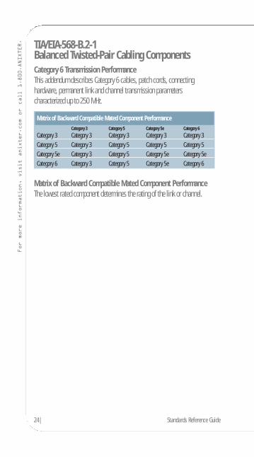
Balanced Twisted-Pair Cabling ComponentsCategory 6 Transmission PerformanceThis addendum describes Category 6 cables, patch cords, connecting hardware, permanent link and channel transmission parameters characterized up to 250 MHz.
Matrix of Backward Compatible Mated Component PerformanceThe lowest rated component determines the rating of the link or channel.
Matrix of Backward Compatible Mated Component PerformanceCategory 3 Category 5 Category 5e Category 6
Category 3 Category 3 Category 3 Category 3 Category 3Category 5 Category 3 Category 5 Category 5 Category 5Category 5e Category 3 Category 5 Category 5e Category 5eCategory 6 Category 3 Category 5 Category 5e Category 6

Products. Technology. Services. Delivered Globally.
Category 6 Solid Horizontal and Backbone Cable (100 m)**Horizontal and backbone cables are defined only as identical 4-pair cables.
Maximum Category 6 cable propagation delay: 538 ns/100 m at 100 MHz (536 at 250 MHz)
Maximum Category 6 cable delay skew: 45 ns/100 m at all frequencies
The PSNEXT performance of bundled or hybrid cables must be 1.2 dB greaterthan shown above.
Category 6 Solid Horizontal and Backbone CableFrequency Insertion NEXT* PSNEXT ELFEXT* PSELFEXT Return(MHz) Loss (dB) (dB) (dB) (dB) (dB) Loss (dB)
1.0 2.0 74.3 72.3 67.8 64.8 20.04.0 3.8 65.3 63.3 55.8 52.8 23.08.0 5.3 60.8 58.8 49.7 46.7 24.510.0 6.0 59.3 57.3 47.8 44.8 25.016.0 7.6 56.2 54.2 43.7 40.7 25.020.0 8.5 54.8 52.8 41.8 38.8 25.025.0 9.5 53.3 51.3 39.8 36.8 24.331.25 10.7 51.9 49.9 37.9 34.9 23.662.5 15.4 47.4 45.4 31.9 28.9 21.5100.0 19.8 44.3 42.3 27.8 24.8 20.1200.0 29.0 39.8 37.8 21.8 18.8 18.0250.0 32.8 38.3 36.3 19.8 16.8 17.3
Standards Reference Guide |25
26| Standards Reference Guide
For more information, visit anixter.com or call 1.800.ANIXTER.
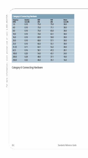
Category 6 Connecting Hardware
Category 6 Connecting HardwareFrequency Insertion NEXT FEXT Return(MHz) Loss (dB) (dB) (dB) Loss (dB)
1.0 0.10 75.0 75.0 30.04.0 0.10 75.0 71.1 30.08.0 0.10 75.0 65.0 30.010.0 0.10 74.0 63.1 30.016.0 0.10 69.9 59.0 30.020.0 0.10 68.0 57.1 30.025.0 0.10 66.0 55.1 30.031.25 0.11 64.1 53.2 30.062.5 0.16 58.1 47.2 28.1100.0 0.20 54.0 43.1 24.0200.0 0.28 48.0 37.1 18.0250.0 0.32 46.0 35.1 16.0
Products. Technology. Services. Delivered Globally.
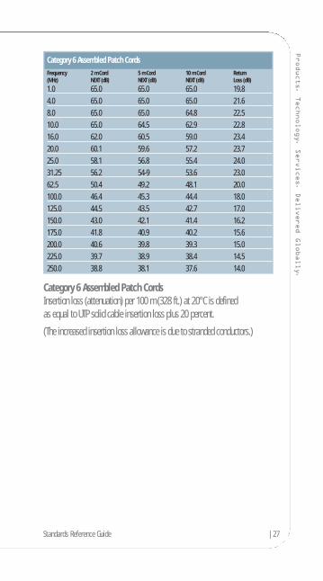
Category 6 Assembled Patch CordsInsertion loss (attenuation) per 100 m (328 ft.) at 20°C is defined as equal to UTP solid cable insertion loss plus 20 percent.
(The increased insertion loss allowance is due to stranded conductors.)
Category 6 Assembled Patch Cords Frequency 2 m Cord 5 m Cord 10 m Cord Return(MHz) NEXT (dB) NEXT (dB) NEXT (dB) Loss (dB)
1.0 65.0 65.0 65.0 19.84.0 65.0 65.0 65.0 21.68.0 65.0 65.0 64.8 22.510.0 65.0 64.5 62.9 22.816.0 62.0 60.5 59.0 23.420.0 60.1 59.6 57.2 23.725.0 58.1 56.8 55.4 24.031.25 56.2 54-9 53.6 23.062.5 50.4 49.2 48.1 20.0100.0 46.4 45.3 44.4 18.0125.0 44.5 43.5 42.7 17.0150.0 43.0 42.1 41.4 16.2175.0 41.8 40.9 40.2 15.6200.0 40.6 39.8 39.3 15.0225.0 39.7 38.9 38.4 14.5250.0 38.8 38.1 37.6 14.0
Standards Reference Guide |27

28| Standards Reference Guide
For more information, visit anixter.com or call 1.800.ANIXTER.
Category 6 Permanent LinkMaximum Category 6 permanent link propagation delay: less than 498 ns at 10 MHzMaximum Category 6 permanent link delay skew: less than 44 ns/100 m at 10 MHz
Category 6 ChannelMaximum Category 6 channel propagation delay: less than 555 ns at 10 MHzMaximum Category 6 channel delay skew: less than 50 ns/100m at 10 MHz
Category 6 ChannelFrequency Insertion NEXT PSNEXT ELFEXT PSELFEXT Return(MHz) Loss (dB) (dB) (dB) (dB) (dB) Loss (dB)
1.0 2.1 65.0 62.0 63.3 60.3 19.04.0 4.0 63.0 60.5 51.2 48.2 19.08.0 5.7 58.2 55.6 45.2 42.2 19.010.0 6.3 56.6 54.0 43.3 40.3 19.016.0 8.0 53.2 50.6 39.2 36.2 18.020.0 9.0 51.6 49.0 37.2 34.2 17.525.0 10.1 50.0 47.3 35.3 32.3 17.031.25 11.4 48.4 45.7 33.4 30.4 16.562.5 16.5 43.4 40.6 27.3 24.3 14.0100.0 21.3 39.9 37.1 23.3 20.3 12.0200.0 31.5 34.8 31.9 17.2 14.2 9.0250.0 35.9 33.1 30.2 15.3 12.3 8.0
Category 6 Permanent Link Frequency Insertion NEXT PSNEXT ELFEXT PSELFEXT Return(MHz) Loss (dB) (dB) (dB) (dB) (dB) Loss (dB)
1.0 1.9 65.0 62.0 64.2 61.2 19.14.0 3.5 64.1 61.8 52.1 49.1 21.08.0 5.0 59.4 57.0 46.1 43.1 21.010.0 5.5 57.8 55.5 44.2 41.2 21.016.0 7.0 54.6 52.2 40.1 37.1 20.020.0 7.9 53.1 50.7 38.2 35.2 19.525.0 8.9 51.5 49.1 36.2 33.2 19.031.25 10.0 50.0 47.5 34.3 31.3 18.562.5 14.4 45.1 42.7 28.3 25.3 16.0100.0 18.6 41.8 39.3 24.2 21.2 14.0200.0 27.4 36.9 34.3 18.2 15.2 11.0250.0 31.1 35.3 32.7 16.2 13.2 10.0

Products. Technology. Services. Delivered Globally.
Category 6 Longitudinal Conversion Loss (LCL)Longitudinal Conversion Transfer Loss (LCTL) is not yet defined.
Note: This table compares current TIA Category 6 cabling with new TIA and ISOspecifications for 10 Gigabit cabling. This table summarizes the various UTPcabling options and their respective 10 Gigabit performance attributes asdefined by the latest standards. Category 5e is not recognized as a viablecabling media to support 10 Gigabit transmission regardless of its installedcabling distance. Category 6 cabling will only support 10 Gigabit Ethernet at a maximum installed distance of 55 meters.
TIA Category 6 versus Augmented Category 6TIA Category TIA Category TIA Augmented ISO Class EA5e UTP 6 UTP Category 6 UTP
Recognized by IEEE 802.3an No Yes Yes Yes55 MeterDistance Support No Yes Yes Yes100 MeterDistance Support No No Yes YesExtrapolated Test Limits for NEXTand PSNEXTto 500 MHz No No No Yes
Category 6 Longitudinal Conversion Loss (LCL)Frequency Cable Connector(MHz) LCL (dB) LCL (dB)
1.0 40.0 40.04.0 40.0 40.08.0 40.0 40.010.0 40.0 40.016.0 38.0 40.020.0 37.0 40.025.0 36.0 40.031.25 35.1 38.162.5 32.0 32.1100.0 30.0 28.0200.0 27.0 22.0250.0 26.0 20.0
Standards Reference Guide |29
30| Standards Reference Guide
For more information, visit anixter.com or call 1.800.ANIXTER. TIA/EIA-568-B.2-Addendum 10
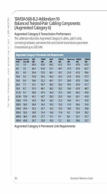
Balanced Twisted-Pair Cabling Components(Augmented Category 6)Augmented Category 6 Transmission PerformanceThis addendum describes Augmented Category 6 cables, patch cords,connecting hardware, permanent link and channel transmission parameterscharacterized up to 500 MHz.
Augmented Category 6 Permanent Link Requirements
Augmented Category 6 Permanent Link RequirementsFrequency Insertion NEXT PSNEXT ACR-F PSACR-F Return Loss PSANEXT PSAACRF(MHz) Loss (dB) (dB) (dB) (dB) (dB) (dB) (dB) (dB)
1.0 1.9 65.0 62.0 64.2 61.2 19.1 67.0 67.04.0 3.5 64.1 61.8 52.1 49.1 21.0 67.0 65.78.0 4.9 59.4 57.0 46.1 43.1 21.0 67.0 59.610.0 5.5 57.8 55.5 44.2 41.2 21.0 67.0 57.716.0 6.9 54.6 52.2 40.1 37.1 20.0 67.0 53.620.0 7.7 53.1 50.7 38.2 35.2 19.5 67.0 51.725.0 8.7 51.5 49.1 36.2 33.2 19.0 67.0 49.731.25 9.7 50.0 47.5 34.3 31.3 18.5 66.2 47.862.50 13.9 45.1 42.7 28.3 25.3 16.0 63.1 41.8100.0 17.9 41.8 39.3 24.2 21.2 14.0 61.1 37.8200.0 26.0 36.9 34.3 18.2 15.2 11.0 56.6 31.8250.0 29.4 35.3 32.7 16.2 13.2 10.0 55.5 29.8300.0 32.6 34.0 31.4 14.6 11.6 9.2 53.9 28.2400.0 38.4 29.9 27.1 12.1 9.1 8.0 52.1 25.7500.0 43.8 26.7 23.8 10.2 7.2 8.0 50.6 23.7

Products. Technology. Services. Delivered Globally.Augmented Category 6 Channel Requirements
Note: The requirements for ISO (the International Organization forStandardization) 11801 Class EA are more demanding compared to the TIA/EIA Augmented Category 6 requirements. Anixter’s Infrastructure SolutionsLab tests to the more stringent ISO 11801 standards.
Note: See the IEEE 802.3an and ISO Class EA section of this book for moreinformation on 10 Gigabit cabling and protocol methods.
ISO Compared to TIACharacteristics 500 MHz (dB) ISO Class EA TIA Augmented Category 6PSNEXT Loss 24.8 dB 23.2 dBNEXT Loss 27.9 dB 26.1 dBPSANEXT Loss 49.5 dB 49.5 dBReturn Loss 6.0 dB 6.0 dBInsertion Loss 49.3 dB 49.3 dBReferred to by IEEE Yes No
Augmented Category 6 Channel RequirementFrequency Insertion NEXT PSNEXT ACR-F PSACR-F Return Loss PSANEXT PSAACRF(MHz) Loss (dB) (dB) (dB) (dB) (dB) (dB) (dB) (dB)
1.0 2.2 65.0 62.0 63.3 60.3 19.0 67.0 67.04.0 4.1 63.0 60.5 51.2 48.2 19.0 67.0 65.08.0 5.7 58.2 55.6 45.2 42.2 19.0 67.0 58.910.0 6.4 56.6 54.0 43.3 40.3 19.0 67.0 57.016.0 8.1 53.2 50.6 39.2 36.2 18.0 67.0 52.920.0 9.1 51.6 49.0 37.2 34.2 17.5 67.0 51.025.0 10.2 50.0 47.3 35.3 32.3 17.0 66.0 49.031.25 11.4 48.4 45.7 33.4 30.4 16.5 65.1 47.162.50 16.3 43.4 40.6 27.3 24.3 14.0 62.0 41.1100.0 20.8 39.9 37.1 23.3 20.3 12.0 60.0 37.0200.0 30.0 34.8 31.9 17.2 14.2 9.0 55.5 31.0250.0 33.8 33.1 30.2 15.3 12.3 8.0 54.0 29.0300.0 37.3 31.7 28.8 13.7 10.7 7.2 52.8 27.5400.0 43.6 28.7 25.8 11.2 8.2 6.0 51.0 25.0500.0 49.3 26.1 23.2 9.3 6.3 6.0 49.5 23.0
Standards Reference Guide |31
32| Standards Reference Guide
For more information, visit anixter.com or call 1.800.ANIXTER. TIA/EIA-568-B.3
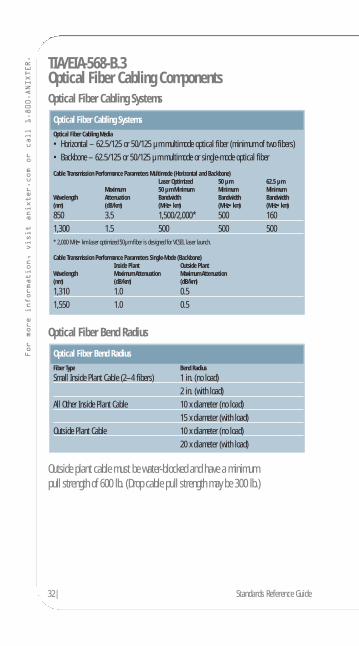
Optical Fiber Cabling ComponentsOptical Fiber Cabling Systems
Optical Fiber Bend Radius
Outside plant cable must be water-blocked and have a minimumpull strength of 600 lb. (Drop cable pull strength may be 300 lb.)
Optical Fiber Bend RadiusFiber Type Bend Radius
Small Inside Plant Cable (2–4 fibers) 1 in. (no load)2 in. (with load)
All Other Inside Plant Cable 10 x diameter (no load)15 x diameter (with load)
Outside Plant Cable 10 x diameter (no load)20 x diameter (with load)
Optical Fiber Cabling SystemsOptical Fiber Cabling Media
• Horizontal – 62.5/125 or 50/125 µm multimode optical fiber (minimum of two fibers)• Backbone – 62.5/125 or 50/125 µm multimode or single-mode optical fiber
Cable Transmission Performance Parameters Multimode (Horizontal and Backbone)Laser Optimized 50 µm 62.5 µm
Maximum 50 µm Minimum Minimum MinimumWavelength Attenuation Bandwidth Bandwidth Bandwidth(nm) (dB/km) (MHz•km) (MHz•km) (MHz•km)
850 3.5 1,500/2,000* 500 1601,300 1.5 500 500 500* 2,000 MHz•km laser optimized 50µm fiber is designed for VCSEL laser launch.
Cable Transmission Performance Parameters Single-Mode (Backbone)Inside Plant Outside Plant
Wavelength Maximum Attenuation Maximum Attenuation(nm) (dB/km) (dB/km)
1,310 1.0 0.51,550 1.0 0.5
Products. Technology. Services. Delivered Globally.
Optical Fiber ConnectorNo specified connector: 568SC and other duplex designs may be used.
Color Identification• Beige – multimode connector/coupling• Blue – single-mode connector/coupling
Note: The ISO/IEC standard now specifies the 568SC-type fiber connector in the work area.
Optical Fiber Telecommunications Outlet
Required Features• Capability to terminate minimum of two fibers into 568SC
couplings or other duplex connection• Means of securing fiber and maintaining minimum
bend radius of 25 mm (1 in.)
Optical Fiber Splices, Fusion or Mechanical• Maximum insertion loss 0.3 dB• Minimum return loss:
– Multimode: 20 dB– Single-mode: 26 dB– Single-mode: 55 dB (analog CATV)
Optical Fiber Connector (mated pair)• Maximum insertion loss 0.75 dB
Patch Cords• Shall be dual fiber of the same type as the horizontal and backbone fiber• Polarity shall be keyed duplex
For more information on Fibre Channel, order Anixter’s Data Center Resource Guide atanixter.com/datacenterguide.
Standards Reference Guide |33
34| Standards Reference Guide
For more information, visit anixter.com or call 1.800.ANIXTER. Purpose of the ANSI/TIA/EIA-569-B Standard
As the complexity of voice and data telecommunications has increased,standards have been established to ensure the operability, flexibility,manageability and longevity of these critical commercial support systems.Telecommunications systems now encompass voice, data and videotransmission of business information, fire and security, audio, environmentaland other intelligent building controls over media that include fiber optics,specialized copper data cabling, microwave and radio wave. This sectionconcisely describes the architectural design elements of cabling pathways and dedicated rooms for telecommunications equipment.
A multitenant commercial building has a life expectancy of at least 50 years.Software, hardware and communications gear have a far shorter life span of one to five years. Moreover, in a multitenant environment, continuous moves,adds and changes are inevitable. Standards help to guide the design of currentsystems to ease future changes. By planning for the future, these standardsintend to provide a generic structured cabling plant capable of running any voice or data application foreseeable in the next 10 to 15 years.
Abbreviations:
AWG American Wire GaugeV VoltsA AmpskVA Kilovolt ampereV/m Volts per meter
Products. Technology. Services. Delivered Globally.
Section Contents
ANSI/TIA/EIA-569-BCommercial Building Standard for Telecommunications Pathways and Spaces
Pathways and Spaces . . . . . . . . . . . . . . . . . . . . . . . . . . . . . . . . . . . . . . . . . . . 36Design Considerations . . . . . . . . . . . . . . . . . . . . . . . . . . . . . . . . . . . . . . . . . . 37
Entrance Facilities . . . . . . . . . . . . . . . . . . . . . . . . . . . . . . . . . . . . . . . . . . 37Service Entrance Pathways . . . . . . . . . . . . . . . . . . . . . . . . . . . . . . . . . . . . 37Equipment Room . . . . . . . . . . . . . . . . . . . . . . . . . . . . . . . . . . . . . . . . . . . 38Intrabuilding Backbone Pathways . . . . . . . . . . . . . . . . . . . . . . . . . . . . . . 40Telecommunications Room . . . . . . . . . . . . . . . . . . . . . . . . . . . . . . . . . . . . 41Horizontal Pathways . . . . . . . . . . . . . . . . . . . . . . . . . . . . . . . . . . . . . . . . . 42
Underfloor Duct . . . . . . . . . . . . . . . . . . . . . . . . . . . . . . . . . . . . . . . . . 42Flushduct . . . . . . . . . . . . . . . . . . . . . . . . . . . . . . . . . . . . . . . . . . . . . . 42Multichannel Raceway . . . . . . . . . . . . . . . . . . . . . . . . . . . . . . . . . . . . 42Cellular Floor . . . . . . . . . . . . . . . . . . . . . . . . . . . . . . . . . . . . . . . . . . . 42Trenchduct . . . . . . . . . . . . . . . . . . . . . . . . . . . . . . . . . . . . . . . . . . . . . 42Access Floor . . . . . . . . . . . . . . . . . . . . . . . . . . . . . . . . . . . . . . . . . . . . 42Plenum and Ceiling . . . . . . . . . . . . . . . . . . . . . . . . . . . . . . . . . . . . . . . 42Conduit . . . . . . . . . . . . . . . . . . . . . . . . . . . . . . . . . . . . . . . . . . . . . . . . 43Cable Trays . . . . . . . . . . . . . . . . . . . . . . . . . . . . . . . . . . . . . . . . . . . . . 43Perimeter Pathways . . . . . . . . . . . . . . . . . . . . . . . . . . . . . . . . . . . . . . 43
Consolidation Points and MUTOAs . . . . . . . . . . . . . . . . . . . . . . . . . . . . . . . . . 45Electromagnetic Interference . . . . . . . . . . . . . . . . . . . . . . . . . . . . . . . . . . . . . 45Firestops . . . . . . . . . . . . . . . . . . . . . . . . . . . . . . . . . . . . . . . . . . . . . . . . . . . . . 46
Standards Reference Guide |35
36| Standards Reference Guide
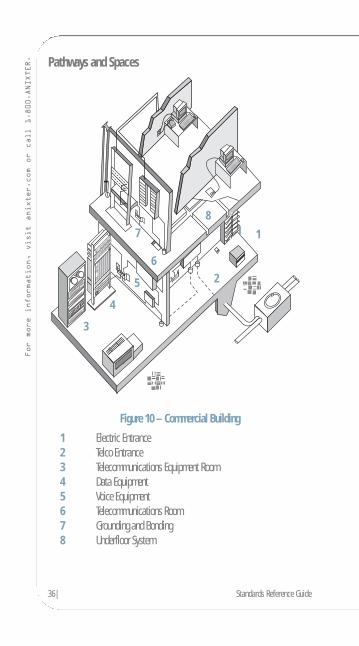
For more information, visit anixter.com or call 1.800.ANIXTER. Pathways and Spaces
Figure 10 – Commercial Building
1 Electric Entrance2 Telco Entrance3 Telecommunications Equipment Room4 Data Equipment5 Voice Equipment6 Telecommunications Room7 Grounding and Bonding8 Underfloor System
1
2
3
4
5
6
78
1
Products. Technology. Services. Delivered Globally.
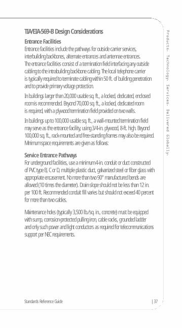
TIA/EIA-569-B Design ConsiderationsEntrance FacilitiesEntrance facilities include the pathways for outside carrier services,interbuilding backbones, alternate entrances and antennae entrances.The entrance facilities consist of a termination field interfacing any outsidecabling to the intrabuilding backbone cabling. The local telephone carrier is typically required to terminate cabling within 50 ft. of building penetrationand to provide primary voltage protection.
In buildings larger than 20,000 usable sq. ft., a locked, dedicated, enclosedroom is recommended. Beyond 70,000 sq. ft., a locked, dedicated room is required, with a plywood termination field provided on two walls.
In buildings up to 100,000 usable sq. ft., a wall-mounted termination field may serve as the entrance facility, using 3/4-in. plywood, 8-ft. high. Beyond100,000 sq. ft., rack-mounted and free-standing frames may also be required.Minimum space requirements are given as follows:
Service Entrance PathwaysFor underground facilities, use a minimum 4-in. conduit or duct constructed of PVC type B, C or D, multiple plastic duct, galvanized steel or fiber glass withappropriate encasement. No more than two 90° manufactured bends areallowed (10 times the diameter). Drain slope should not be less than 12 in. per 100 ft. Recommended conduit fill varies but should not exceed 40 percentfor more than two cables.
Maintenance holes (typically 3,500 lb./sq. in., concrete) must be equipped with sump, corrosion-protected pulling iron, cable racks, grounded ladder and only such power and light conductors as required for telecommunicationssupport per NEC requirements.
Standards Reference Guide |37
38| Standards Reference Guide
For more information, visit anixter.com or call 1.800.ANIXTER.
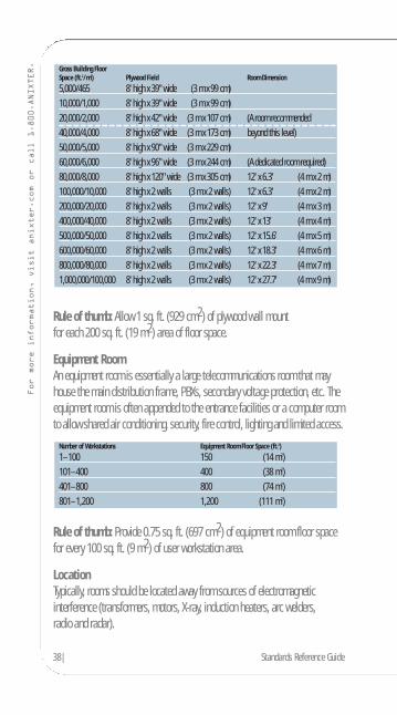
Rule of thumb: Allow 1 sq. ft. (929 cm2) of plywood wall mount for each 200 sq. ft. (19 m2) area of floor space.
Equipment RoomAn equipment room is essentially a large telecommunications room that mayhouse the main distribution frame, PBXs, secondary voltage protection, etc. Theequipment room is often appended to the entrance facilities or a computer roomto allow shared air conditioning, security, fire control, lighting and limited access.
Rule of thumb: Provide 0.75 sq. ft. (697 cm2) of equipment room floor spacefor every 100 sq. ft. (9 m2) of user workstation area.
LocationTypically, rooms should be located away from sources of electromagneticinterference (transformers, motors, X-ray, induction heaters, arc welders, radio and radar).
Number of Workstations Equipment Room Floor Space (ft.2)
1–100 150 (14 m2)101–400 400 (38 m2)401–800 800 (74 m2)801–1,200 1,200 (111 m2)
Gross Building FloorSpace (ft.2/ m2) Plywood Field Room Dimension
5,000/465 8' high x 39" wide (3 m x 99 cm)10,000/1,000 8' high x 39" wide (3 m x 99 cm)20,000/2,000 8' high x 42" wide (3 m x 107 cm) (A room recommended40,000/4,000 8' high x 68" wide (3 m x 173 cm) beyond this level)50,000/5,000 8' high x 90" wide (3 m x 229 cm)60,000/6,000 8' high x 96" wide (3 m x 244 cm) (A dedicated room required)80,000/8,000 8' high x 120" wide (3 m x 305 cm) 12' x 6.3' (4 m x 2 m)100,000/10,000 8' high x 2 walls (3 m x 2 walls) 12' x 6.3' (4 m x 2 m)200,000/20,000 8' high x 2 walls (3 m x 2 walls) 12' x 9' (4 m x 3 m)400,000/40,000 8' high x 2 walls (3 m x 2 walls) 12' x 13' (4 m x 4 m)500,000/50,000 8' high x 2 walls (3 m x 2 walls) 12' x 15.6' (4 m x 5 m)600,000/60,000 8' high x 2 walls (3 m x 2 walls) 12' x 18.3' (4 m x 6 m)800,000/80,000 8' high x 2 walls (3 m x 2 walls) 12' x 22.3' (4 m x 7 m)1,000,000/100,000 8' high x 2 walls (3 m x 2 walls) 12' x 27.7' (4 m x 9 m)
Products. Technology. Services. Delivered Globally.
PerimetersTypically, no false ceiling; all surfaces treated to reduce dust; walls and ceilingpainted white or pastel to improve visibility.
Limited AccessTypically, single or double 36 in. x 80 in. lockable doors with no doorsills.
OtherTypically, no piping, ductwork, mechanical equipment or power cabling shouldbe allowed to pass through the equipment room. No unrelated storage.
Ceiling HeightMinimum clear height in room shall be 8 ft. (2.4 m); the height between thefinished floor and the lowest point should be 10 ft. (3 m) to accommodate tallracks and overhead raceways. False ceilings should not be installed.
HVAC24 hours a day, 365 days a year, 64° to 75°F, 30 to 55 percent humidity,positive pressure, with independent power from telecommunications equipment.
LightingTypically, 8.5-ft. high, providing 50 foot-candle at 3 ft. above floor.
ElectricalTypically, a minimum of two dedicated 15 A, 110 V AC duplex outlets onseparate circuits is required. Convenience duplex outlets shall be placed at 6-ft.intervals around the perimeter. Emergency power should be considered andsupplied if available.
Bonding and GroundingAccess shall be available to the bonding and grounding as specified in J-STD-607-A.
DustLess than 100 micrograms/cubic meter per 24 hour period.
Note: The term “typically” is applied here to indicate, where applicable, thatthese requirements also apply to other elements of the cabling system spaces.Lighting requirements, for instance, are largely identical for entrance facilities,equipment rooms and telecommunications rooms.
Standards Reference Guide |39
40| Standards Reference Guide
For more information, visit anixter.com or call 1.800.ANIXTER. Intrabuilding Backbone Pathways
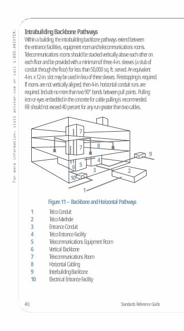
Within a building, the intrabuilding backbone pathways extend between the entrance facilities, equipment room and telecommunications rooms.Telecommunications rooms should be stacked vertically above each other oneach floor and be provided with a minimum of three 4-in. sleeves (a stub ofconduit through the floor) for less than 50,000 sq. ft. served. An equivalent 4-in. x 12-in. slot may be used in lieu of three sleeves. Firestopping is required.If rooms are not vertically aligned, then 4-in. horizontal conduit runs arerequired. Include no more than two 90° bends between pull points. Pulling iron or eyes embedded in the concrete for cable pulling is recommended. Fill should not exceed 40 percent for any run greater than two cables.
Figure 11 – Backbone and Horizontal Pathways
1 Telco Conduit2 Telco Manhole3 Entrance Conduit4 Telco Entrance Facility5 Telecommunications Equipment Room6 Vertical Backbone7 Telecommunications Room8 Horizontal Cabling9 Interbuilding Backbone10 Electrical Entrance Facility
23
4
7
7
5
9
10
6
1
8
Products. Technology. Services. Delivered Globally.
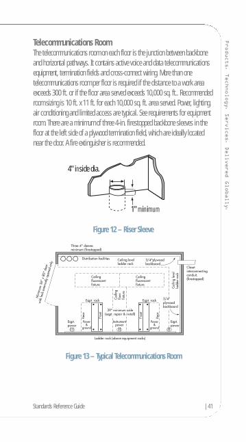
Telecommunications RoomThe telecommunications room on each floor is the junction between backboneand horizontal pathways. It contains active voice and data telecommunicationsequipment, termination fields and cross-connect wiring. More than onetelecommunications room per floor is required if the distance to a work areaexceeds 300 ft. or if the floor area served exceeds 10,000 sq. ft.. Recommendedroom sizing is 10 ft. x 11 ft. for each 10,000 sq. ft. area served. Power, lighting,air conditioning and limited access are typical. See requirements for equipmentroom. There are a minimum of three 4-in. firestopped backbone sleeves in thefloor at the left side of a plywood termination field, which are ideally locatednear the door. A fire extinguisher is recommended.
Figure 12 – Riser Sleeve
Figure 13 – Typical Telecommunications Room
4" inside dia.
1" minimum
Standards Reference Guide |41
42| Standards Reference Guide
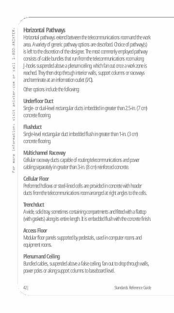
For more information, visit anixter.com or call 1.800.ANIXTER. Horizontal Pathways
Horizontal pathways extend between the telecommunications room and the workarea. A variety of generic pathway options are described. Choice of pathway(s) is left to the discretion of the designer. The most commonly employed pathwayconsists of cable bundles that run from the telecommunications room along J-hooks suspended above a plenum ceiling, which fan out once a work zone isreached. They then drop through interior walls, support columns or racewaysand terminate at an information outlet (I/O).
Other options include the following:
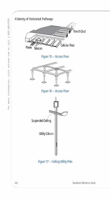
Underfloor DuctSingle- or dual-level rectangular ducts imbedded in greater than 2.5-in. (7 cm)concrete flooring.
FlushductSingle-level rectangular duct imbedded flush in greater than 1-in. (3 cm)concrete flooring.
Multichannel RacewayCellular raceway ducts capable of routing telecommunications and powercabling separately in greater than 3-in. (8 cm) reinforced concrete.
Cellular FloorPreformed hollows or steel-lined cells are provided in concrete with headerducts from the telecommunications room arranged at right angles to the cells.
TrenchductA wide, solid tray, sometimes containing compartments and fitted with a flattop(with gaskets) along its entire length. It is embedded flush with the concrete finish.
Access FloorModular floor panels supported by pedestals, used in computer rooms andequipment rooms.
Plenum and CeilingBundled cables, suspended above a false ceiling, fan out to drop through walls,power poles or along support columns to baseboard level.
Products. Technology. Services. Delivered Globally.
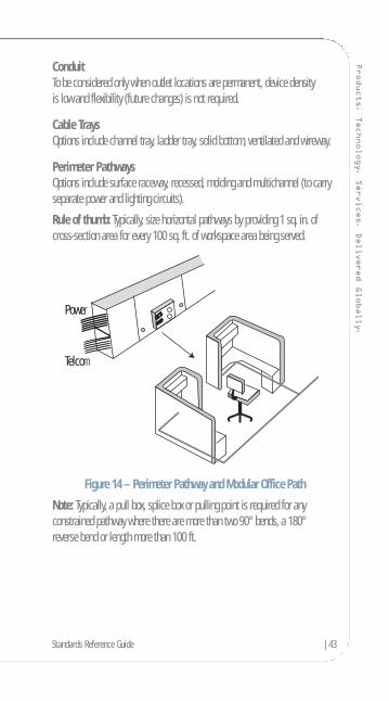
ConduitTo be considered only when outlet locations are permanent, device density is low and flexibility (future changes) is not required.
Cable TraysOptions include channel tray, ladder tray, solid bottom, ventilated and wireway.
Perimeter PathwaysOptions include surface raceway, recessed, molding and multichannel (to carryseparate power and lighting circuits).
Rule of thumb: Typically, size horizontal pathways by providing 1 sq. in. ofcross-section area for every 100 sq. ft. of workspace area being served.
Figure 14 – Perimeter Pathway and Modular Office Path
Note: Typically, a pull box, splice box or pulling point is required for anyconstrained pathway where there are more than two 90° bends, a 180°reverse bend or length more than 100 ft.
Power
Telcom
Standards Reference Guide |43
44| Standards Reference Guide
For more information, visit anixter.com or call 1.800.ANIXTER. A Variety of Horizontal Pathways
Figure 15 – Access Floor
Figure 16 – Access Floor
Figure 17 – Ceiling Utility Pole
Suspended Ceiling
Utility Column
Power
Trench Duct
Cellular FloorTelecom

Products. Technology. Services. Delivered Globally.
Consolidation Points and MUTOAsConsolidation points provide limited area connection access. Typically, a permanent flush wall, ceiling or support column-mounted panel servesmodular furniture work areas. The panels must be unobstructed and fullyaccessible without moving fixtures, equipment or heavy furniture.
A multiuser telecommunications outlet assembly (MUTOA) is anothermethodology to reduce cabling moves, adds and changes in modular furnituresettings. The user cord is directly connected to the MUTOA. A MUTOA locationmust be accessible and permanent and may not be mounted in ceiling spacesor under access flooring. Similarly, it cannot be mounted in furniture unless thatfurniture is permanently secured to the building structure.
For more descriptive information on distance limitations and purposes ofconsolidation points and MUTOAs, see ANSI/TIA/EIA-568-B.1.
Electromagnetic InterferenceVoice and data telecommunications cabling should not be run adjacent andparallel to power cabling – even along short distances – unless one or bothcable types are shielded and grounded. For low-voltage communication cables,a minimum 5-in. distance is required from any fluorescent lighting fixture orpower line over 2 kVA and up to 24 in. from any power line over 5 kVA*. Ingeneral, telecommunications cabling is routed separately several feet away frompower cabling. Similarly, telecommunications cabling is routed away from largemotors, generators, induction heaters, arc welders, X-ray equipment and radiofrequency, microwave or radar sources.
*Note: Distance recommendations from (1990) TIA/EIA-569 are reproducedhere by popular request. For current recommendations, refer to NEC/NFPA 70,Article 800-52.
Standards Reference Guide |45

46| Standards Reference Guide
For more information, visit anixter.com or call 1.800.ANIXTER. Firestops
Annex A of the standard discusses various types of packing used to re-establishthe integrity of fire-rated structures when these barriers have been penetratedby cable. This section of the standard briefly discusses passive mechanicalsystems and non-mechanical systems such as putty, caulk, cements,intumescent sheets and strips, silicone foams and premanufactured pillows. The most common method is stuffing all apertures with ceramic or mineral wooland caulking both sides with fire-resistant putty. The information refers thedesigner to check manufacturer specifications and UL ratings against NFPA,ASTM and NEC codes.
Figure 18 – Cross-Section of Typical Firestop
Firestopping putty or caulk
Metallic conduit sleeve or cable
Ceramic fiber ormineral wool
Wall assembly
Products. Technology. Services. Delivered Globally.
Purpose of the ANSI/TIA/EIA-606-A StandardModern buildings require an effective telecommunications infrastructure to support the wide variety of services that rely on the electronic transport of information. Administration includes basic documentation and timelyupdating of drawings, labels and records. Administration should be synergisticwith voice, data and video telecommunications, as well as with other buildingsignal systems, including security, audio, alarms and energy management.
Administration can be accomplished with paper records, but in today’sincreasingly complex telecommunications environment, effective administrationis enhanced by the use of computer-based systems.
A multitenant commercial building has a life expectancy of at least 50 years.Moreover, in a multitenant environment, continuous moves, adds and changesare inevitable.
Administrative record keeping plays an increasingly necessary role in theflexibility and management of frequent moves, adds and changes. This standardconcisely describes the administrative record keeping elements of a modernstructured cabling system.
Standards Reference Guide |47

48| Standards Reference Guide
For more information, visit anixter.com or call 1.800.ANIXTER. Section Contents
TIA/EIA-606-AAdministration Standard for Commercial Telecommunications Infrastructure
Elements of an Administration System . . . . . . . . . . . . . . . . . . . . . . . . . . . . . . 49Classes of Administration . . . . . . . . . . . . . . . . . . . . . . . . . . . . . . . . . . . . . . . 50Class 1 Administration . . . . . . . . . . . . . . . . . . . . . . . . . . . . . . . . . . . . . . . . . . 51Class 2 Administration . . . . . . . . . . . . . . . . . . . . . . . . . . . . . . . . . . . . . . . . . . 52Class 3 Administration . . . . . . . . . . . . . . . . . . . . . . . . . . . . . . . . . . . . . . . . . . 53Class 4 Administration . . . . . . . . . . . . . . . . . . . . . . . . . . . . . . . . . . . . . . . . . . 54Identification Formats . . . . . . . . . . . . . . . . . . . . . . . . . . . . . . . . . . . . . . . . . . 55Summary of Record Elements . . . . . . . . . . . . . . . . . . . . . . . . . . . . . . . . . . . . . 56Grounding and Bonding Administration . . . . . . . . . . . . . . . . . . . . . . . . . . . . . 57Label Color Coding . . . . . . . . . . . . . . . . . . . . . . . . . . . . . . . . . . . . . . . . . . . . . 57
Products. Technology. Services. Delivered Globally.
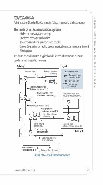
TIA/EIA-606-AAdministration Standard for Commercial Telecommunications Infrastructure
Elements of an Administration System:• Horizontal pathways and cabling• Backbone pathways and cabling• Telecommunications grounding and bonding• Spaces (e.g., entrance facility, telecommunications room, equipment room)• Firestopping
The figure below illustrates a typical model for the infrastructure elements used in an administration system.
Figure 19 – Administration System
Telecommunicationsgrounding and bonding
Entrance facilitydemarcation point
Equipment roommain cross-connect (MC)
Telecommunications roomintermediate cross-connect (IC)
Telecommunications roomhorizontal cross-connect (HC)
Standards Reference Guide |49
50| Standards Reference Guide
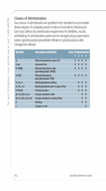
For more information, visit anixter.com or call 1.800.ANIXTER. Classes of Administration
Four classes of administration are specified in this standard to accommodatediverse degrees of complexity present in telecommunications infrastructure.Each class defines the administration requirements for identifiers, records and labeling. An administration system can be managed using a paper-basedsystem, general-purpose spreadsheet software or special-purpose cablemanagement software.
Identifier Description of Identifier Class of Administration1 2 3 4
fs Telecommunications space (TS) R R R Rfs-an Horizontal link R R R Rfs-TGMB Telecommunications main R R R R
grounding busbar (TMGB)fs-TGB Telecommunications R R R R
grounding busbar (TGB)fs1 /fs2-n Building backbone cabling R R Rfs1 /fs2-n.d Building backbone pair or optical fiber R R Rf-FSLn(h) Firestop location R R R[b1-fs1]/[b2-fs2]-n Campus backbone cable R R[b1-fs1]/[b2-fs2]-n/d Campus backbone or optical fiber R Rb Building R Rc Campus or site R
Products. Technology. Services. Delivered Globally.
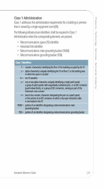
Class 1 AdministrationClass 1 addresses the administration requirements for a building or premisethat is served by a single equipment room (ER).
The following infrastructure identifiers shall be required in Class 1Administration when the corresponding elements are present:
• Telecommunications space (TS) identifier• Horizontal link identifier• Telecommunications main grounding busbar (TMGB)• Telecommunications grounding busbar (TGB)
Class 1 Identifiers
f = numeric character(s) identifying the floor of the building occupied by the TSs = alpha character(s) uniquely identifying the TS on floor f, or the building area
in which the space is locatedfs = the TS identifiera = one or two alpha characters uniquely identifying a single patch panel,
a group of patch panels with sequentially numbered ports, or an IDC connector(punch-down block), or a group of IDC connectors, serving as part of the horizontal cross-connect
n = two to four numeric characters designating the port on a patch panel, or the section of an IDC connector on which a four-pair horizontal cable is terminated in the TS
TMGB = portion of an identifier designating a telecommunications main grounding busbar
TGB = portion of an identifier designating a telecommunications grounding busbar
Standards Reference Guide |51

52| Standards Reference Guide
For more information, visit anixter.com or call 1.800.ANIXTER. Class 2 Administration
Class 2 addresses the administration of infrastructure with one or moretelecommunications spaces (TS) in a single building.
The following infrastructure identifiers shall be required in Class 2Administration when the corresponding elements are present:
• Identifiers required in Class 1 Administration• Building backbone cable identifier• Building backbone pair or optical fiber identifier• Firestopping location identifier
Class 2 Administration may additionally include pathway identifiers.
Class 2 Identifiers
fs1 = TS identifier for the space containing the termination of one end of the backbone cable
fs2 = TS identifier for the space containing the termination of the other end of the backbone cable
n = one or two alphanumeric characters identifying a single cable with one end terminated in the TS designated fs1 and the other end terminated in the TS designated FS2
fs1/fs2-n = a building backbone cable identifierd = two to four numeric characters identifying a single copper pair or
a single optical fiberFSL = an identifier referring to a firestopping location
h = one numeric character specifying the hour rating of a firestopping system
Products. Technology. Services. Delivered Globally.
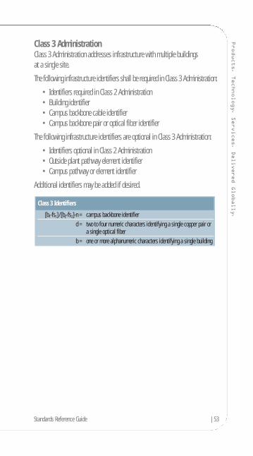
Class 3 AdministrationClass 3 Administration addresses infrastructure with multiple buildings at a single site.
The following infrastructure identifiers shall be required in Class 3 Administration:
• Identifiers required in Class 2 Administration• Building identifier• Campus backbone cable identifier• Campus backbone pair or optical fiber identifier
The following infrastructure identifiers are optional in Class 3 Administration:
• Identifiers optional in Class 2 Administration• Outside plant pathway element identifier• Campus pathway or element identifier
Additional identifiers may be added if desired.
Class 3 Identifiers
[b1-fs1]/[b2-fs2]-n = campus backbone identifierd = two to four numeric characters identifying a single copper pair or
a single optical fiberb = one or more alphanumeric characters identifying a single building
Standards Reference Guide |53

54| Standards Reference Guide
For more information, visit anixter.com or call 1.800.ANIXTER. Class 4 Administration
Class 4 Administration addresses infrastructure with multiple sites or campuses.
The following infrastructure identifiers shall be required in Class 4 Administration:
• Identifiers required in Class 3 Administration• Campus or site identifier
The following infrastructure identifiers are optional in Class 4 Administration:
• Identifiers optional in Class 3 Administration• Intercampus element identifier
Additional identifiers may be added if desired.
Class 4 Identifiers
c = one or more alphanumeric characters identifying a campus or a site

Products. Technology. Services. Delivered Globally.
Identification FormatsA unique alphanumeric identification code is created for every location, pathway,cable and termination point. The standard includes these suggestions:
Identification Format ExampleThe actual format in the preceding chart is not mandated by the standard.However, the chosen format must be consistent and provide a unique identifiernumber for each system element. This method lends itself to organizing andupdating multiple records by the use of powerful relational database (three-dimensional spreadsheet) programs.
Identification ExampleJ0001 Label for an information outlet jackD306 Designation for a work area3A-C17-005 Termination in closet 3A, column C, row 17,
block position 005
Examples like those above (taken from the TIA/EIA 606-A text and administrativelabeling map) indicate the flexibility of conventions that can be established forpurposes of naming. Logical naming conventions can also convey considerableadditional information about other linkages. Further examples are included inthe complete standard.
Alphanumeric Identification Code
BCxxx bonding conductor HHxxx handholeBCDxxx backbone conduit ICxxx intermediate cross-connectCxxx cable Jxxx jackCBxxx backbone cable MCxxx main cross-connectCDxxx conduit MHxxx manhole or maintenance holeCTxxx cable tray PBxxx pull boxECxxx equipment (bonding) conductor Sxxx spliceEFxxx entrance facility SExxx service entranceERxxx equipment room SLxxx sleeveFxxx fiber TCxxx telecommunications closetGBxxx grounding busbar TGBxxx telecommunications grounding busbarGCxxx grounding conductor TMGB telecommunications main grounding
busbarWAxxx work area
Standards Reference Guide |55

56| Standards Reference Guide
For more information, visit anixter.com or call 1.800.ANIXTER. Summary of Record Elements
This table outlines the minimum required information and required linkages.Further information is optional. A multidimensional database or spreadsheet is helpful.
Record Required Information Required Linkages
Pathway Pathway Identification # Cable Records
Pathway Type Space Records
Pathways Pathway Fill Pathway Records
& Pathway Load Grounding Records
Spaces Space Space Identification # Pathway Records
Space Type Cable Records
Grounding Records
Cable Cable Identification # Termination Records
Cable Type Splice Records
Unterminated Pair #s Pathway Records
Damaged Pair #s Grounding Records
Available Pair #s
Termination Termination Hardware #s Termination Position Records
Wiring Hardware Termination Hardware Type Space Records
Damaged Position #s Grounding Records
Termination Termination Position # Cable Records
Position Termination Position Type Other Termination Records
User Code Termination Hardware Records
Cable Pair/Condition #s Space Records
Splice Splice Identification # Cable Records
Splice Type Space Records
TMGB TMGB Identification # Bonding Conductor Records
Busbar Type Space Records
Grounding Conductor #s
Resistance to Earth
Date of Measurement
Grounding Bonding Bonding Conductor ID# Grounding Busbar Records
Conductor Type Pathway Records
Conductor Busbar Identification #
TGB Busbar Identification # Bonding Conductor Records
Busbar Type Space Records
Products. Technology. Services. Delivered Globally.
Grounding and Bonding AdministrationTelecommunications systems require a reliable electrical ground referencepotential, provided by a dedicated grounding and bonding conductor network.
Bonding conductor cabling shall be colored green or labeled appropriately withan alphanumeric identifier and warning label. Grounding records are similar tocable record format.
Grounding and Bonding Terms (with abbreviations):TMGB Telecommunications Main Grounding Busbar
TBB Telecommunications Bonding Backbone
TGB Telecommunications Grounding Busbar
TBBIBC Telecommunications Bonding Backbone Interconnecting BondingConductor
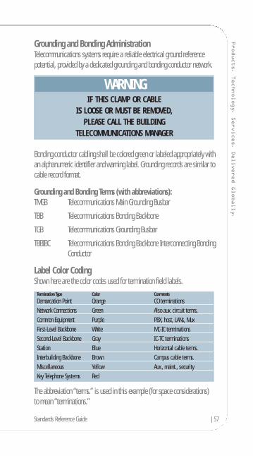
Label Color CodingShown here are the color codes used for termination field labels.
The abbreviation “terms.” is used in this example (for space considerations) to mean “terminations.”
Termination Type Color Comments
Demarcation Point Orange CO terminationsNetwork Connections Green Also aux. circuit terms.Common Equipment Purple PBX, host, LANs, MuxFirst-Level Backbone White MC-IC terminationsSecond-Level Backbone Gray IC-TC terminationsStation Blue Horizontal cable terms.Interbuilding Backbone Brown Campus cable terms.Miscellaneous Yellow Aux., maint., securityKey Telephone Systems Red
WARNINGIF THIS CLAMP OR CABLE
IS LOOSE OR MUST BE REMOVED,PLEASE CALL THE BUILDING
TELECOMMUNICATIONS MANAGER
Standards Reference Guide |57
58| Standards Reference Guide
For more information, visit anixter.com or call 1.800.ANIXTER. The Purpose of the J-STD-607-A Standard
This standard specifies a uniform telecommunications grounding and bondinginfrastructure that shall be followed within commercial buildings. Following the AT&T divestiture of 1984, the end-user became responsible for all premisescabling for voice and data. Advancements in voice communications and theconvergence of voice and data communications led to increasingly complexinteractive systems owned and maintained by the end-user. These systemsrequire a reliable electrical ground-reference potential. Grounding by attachment to the nearest piece of iron pipe is no longer satisfactory to provide ground-reference for sophisticated active electronics systems.
Products. Technology. Services. Delivered Globally.
Section Contents
J-STD-607-ACommercial Building Grounding and Bonding Requirements for Telecommunications
Design Considerations . . . . . . . . . . . . . . . . . . . . . . . . . . . . . . . . . . . . . . . . . . 60Terms . . . . . . . . . . . . . . . . . . . . . . . . . . . . . . . . . . . . . . . . . . . . . . . . . . . . . .60Schematic Diagram . . . . . . . . . . . . . . . . . . . . . . . . . . . . . . . . . . . . . . . . . . . . 61
Standards Reference Guide |59
60| Standards Reference Guide
For more information, visit anixter.com or call 1.800.ANIXTER. Design Considerations
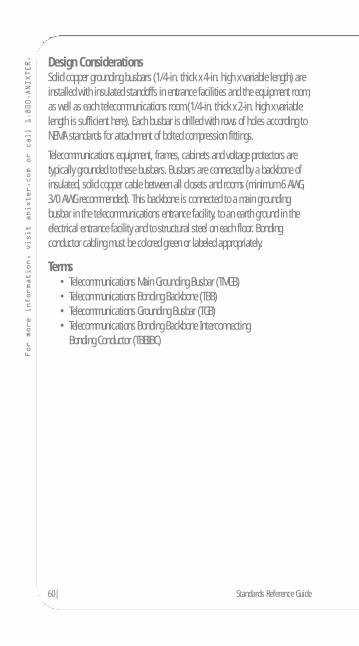
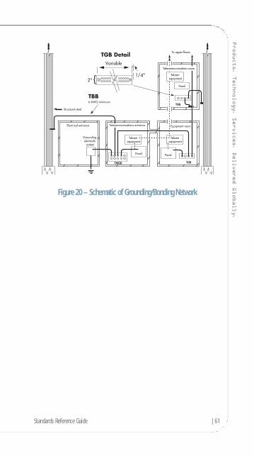
Solid copper grounding busbars (1/4-in. thick x 4-in. high x variable length) areinstalled with insulated standoffs in entrance facilities and the equipment room,as well as each telecommunications room (1/4-in. thick x 2-in. high x variablelength is sufficient here). Each busbar is drilled with rows of holes according toNEMA standards for attachment of bolted compression fittings.
Telecommunications equipment, frames, cabinets and voltage protectors aretypically grounded to these busbars. Busbars are connected by a backbone ofinsulated, solid copper cable between all closets and rooms (minimum 6 AWG,3/0 AWG recommended). This backbone is connected to a main groundingbusbar in the telecommunications entrance facility, to an earth ground in theelectrical entrance facility and to structural steel on each floor. Bondingconductor cabling must be colored green or labeled appropriately.
Terms• Telecommunications Main Grounding Busbar (TMGB)• Telecommunications Bonding Backbone (TBB)• Telecommunications Grounding Busbar (TGB)• Telecommunications Bonding Backbone Interconnecting
Bonding Conductor (TBBIBC)
Products. Technology. Services. Delivered Globally.
Figure 20 – Schematic of Grounding/Bonding Network
Standards Reference Guide |61
62| Standards Reference Guide
For more information, visit anixter.com or call 1.800.ANIXTER. The Purpose of the ANSI/TIA/EIA-942 Standard
• The purpose of this standard is to provide requirements and guidelines for the design and installation of a data center or computer room.
• It is intended for designers who need a comprehensive understanding of the data center design including the facility planning, the cablingsystem and the network design.
• It facilitates the planning for data centers to occur earlier in the buildingdevelopment process (architectural, facilities and IT).
Data centers support a wide range of transmission protocols. Some of theseprotocols impose distance restrictions that are shorter than those imposed by this standard. When applying specific transmission protocols, consultstandards, regulations, equipment manufacturers and system service suppliers for applicability, limitations and ancillary requirements. Consider consolidatingstandardized and proprietary cabling into a single structured cabling system.
The Standard Specifies:
• Cabling design • Network design• Facilities design • Informative annexes containing best practices and availability requirements• Spaces• Pathways• Racks and cabinets.
Products. Technology. Services. Delivered Globally.
Section Contents
ANSI/TIA/EIA-942Telecommunications Infrastructure Standard for Data Centers
Data Center Cabling Infrastructure . . . . . . . . . . . . . . . . . . . . . . . . . . . . . . . . .64Hot and Cold Aisles . . . . . . . . . . . . . . . . . . . . . . . . . . . . . . . . . . . . . . . . . . . . .65Horizontal Cabling . . . . . . . . . . . . . . . . . . . . . . . . . . . . . . . . . . . . . . . . . . . . . .66Backbone Cabling . . . . . . . . . . . . . . . . . . . . . . . . . . . . . . . . . . . . . . . . . . . . . .67Recognized Cabling Media for Horizontal and Backbone Applications . . . . . .68Redundancy . . . . . . . . . . . . . . . . . . . . . . . . . . . . . . . . . . . . . . . . . . . . . . . . . . .69
Standards Reference Guide |63

64| Standards Reference Guide
For more information, visit anixter.com or call 1.800.ANIXTER. Data Center Cabling Infrastructure
The basic elements of the data center’s cabling system include the following:
• Horizontal cabling • Backbone cabling • Cross-connect in the entrance room or main distribution area• Main cross-connect (MC) in the main distribution area• Horizontal cross-connect (HC) in the telecommunications room, horizontal
distribution area or main distribution area• Zone outlet or consolidation point in the zone distribution area• Outlet in the equipment distribution area
Figure 21 – Data Center Cabling Infrastructure
Computer Room
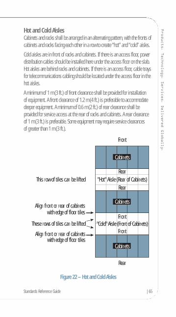
Products. Technology. Services. Delivered Globally.
Hot and Cold AislesCabinets and racks shall be arranged in an alternating pattern, with the fronts ofcabinets and racks facing each other in a row to create “hot” and “cold” aisles.
Cold aisles are in front of racks and cabinets. If there is an access floor, powerdistribution cables should be installed here under the access floor on the slab.Hot aisles are behind racks and cabinets. If there is an access floor, cable traysfor telecommunications cabling should be located under the access floor in thehot aisles.
A minimum of 1 m (3 ft.) of front clearance shall be provided for installation of equipment. A front clearance of 1.2 m (4 ft.) is preferable to accommodatedeeper equipment. A minimum of 0.6 m (2 ft.) of rear clearance shall beprovided for service access at the rear of racks and cabinets. A rear clearanceof 1 m (3 ft.) is preferable. Some equipment may require service clearances of greater than 1 m (3 ft.).
Figure 22 – Hot and Cold Aisles
This row of tiles can be lifted
These rows of tiles can be lifted
Align front or rear of cabinetswith edge of floor tiles
Align front or rear of cabinetswith edge of floor tiles
Cabinets
Cabinets
Cabinets
Rear
Rear
Rear
"Hot" Aisle (Rear of Cabinets)
"Cold" Aisle (Front of Cabinets)
Front
Front
Front
Standards Reference Guide |65
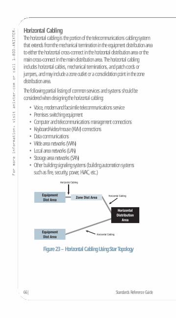
66| Standards Reference Guide
For more information, visit anixter.com or call 1.800.ANIXTER. Horizontal Cabling
The horizontal cabling is the portion of the telecommunications cabling systemthat extends from the mechanical termination in the equipment distribution areato either the horizontal cross-connect in the horizontal distribution area or themain cross-connect in the main distribution area. The horizontal cablingincludes horizontal cables, mechanical terminations, and patch cords orjumpers, and may include a zone outlet or a consolidation point in the zonedistribution area.
The following partial listing of common services and systems should beconsidered when designing the horizontal cabling:
• Voice, modem and facsimile telecommunications service• Premises switching equipment• Computer and telecommunications management connections• Keyboard/video/mouse (KVM) connections• Data communications• Wide area networks (WAN)• Local area networks (LAN)• Storage area networks (SAN)• Other building signaling systems (building automation systems
such as fire, security, power, HVAC, etc.)
Figure 23 – Horizontal Cabling Using Star Topology

Products. Technology. Services. Delivered Globally.
Backbone CablingThe function of the backbone cabling is to provide connections between themain distribution area, the horizontal distribution area and entrance facilities in the data center cabling system. Backbone cabling consists of the backbonecables, main cross-connects, horizontal cross-connects, mechanical terminationsand patch cord or jumpers used for backbone-to-backbone cross-connection.
Figure 24 – Backbone Cabling Using Star Topology
24 AWG UTP/24 ScTP Patch Cords 26 AWG ScTP Patch Cords
Maximum Combined Maximum Combined Length of Zone Area Length of Zone Area
Length of Maximum Length Cables, Patch Cords Maximum Length Cables, Patch CordsHorizontal Cable (H) of Zone Area Cable (Z) and Equipment (C) of Zone Area Cable (Z) and Equipment Cable (C)m (ft.) m (ft.) m (ft.) m (ft.) m (ft.)
90 (295) 5 (16) 10 (33) 4 (13) 8 (26)85 (279) 9 (30) 14 (46) 7 (23) 11 (35)80 (262) 13 (44) 18 (59) 11 (35) 15 (49)75 (246) 17 (57) 22 (72) 14 (46) 18 (59)70 (230) 22 (72) 27 (89) 17 (56) 21 (70)
Standards Reference Guide |67

68| Standards Reference Guide
For more information, visit anixter.com or call 1.800.ANIXTER. Recognized Cabling Media for Horizontal and
Backbone ApplicationsRecognized cables, associated connecting hardware, jumpers, patch cords,equipment cords and zone area cords shall meet all applicable requirementsspecified in ANSI/TIA/EIA-568-B.2 and ANSI/TIA/EIA-568-B.3.
• 100-ohm twisted-pair cable (ANSI/TIA/EIA-568-B.2), Category 6recommended (ANSI/TIA/EIA-568-B.2-1)
• Multimode optical fiber cable, either 62.5/125 µ or 50/125 µ(ANSI/TIA/EIA-568-B.3), 50/125 µ 850 nm laser-optimized multimodefiber is recommended (ANSI/TIA-568-B.3-1)
• Single-mode optical fiber cable (ANSI/TIA/EIA-568-B.3)• The recognized coaxial media are 75-ohm (734 and 735 type) coaxial
cable (Telcordia Technologies GR-139-CORE) and coaxial connector (ANSI T1.404)

Products. Technology. Services. Delivered Globally.
RedundancyData centers that are equipped with diverse telecommunications facilities maybe able to continue their function under catastrophic conditions that wouldotherwise interrupt the data center’s telecommunications service. This standardincludes four tiers relating to various levels of availability of the data centerfacility infrastructure. The tiers are related to research conducted by the Uptime Institute, which defines four tiers of performance as shown in thefollowing table.
Tier I: Tier II: Tier III: Tier IV:Basic Redundant Concurrently Fault
Components Maintainable TolerantNumber of Delivery paths Only 1 Only 1 1 Active, 1 Passive 2 Active
Redundant Components N N+1 N+1 2 (N+1) S+SSupport Space to Raised Floor Ratio 20% 30% 80-90% 100%Initial Watts/ft. 20-30 40-50 40-60 50-80Ultimate Watts/ft. 20-30 40-50 100-150 150+Raised Floor Height 12 in. 18 in. 30-36 in. 30-36 in.Floor LoadingPounds/ft. 85 100 150 150+Utility Voltage 208, 480 208, 480 12-15kV 12-15kVMonths to Implement 3 3 to 6 15 to 20 15 to 20Year FirstDeployed 1965 1970 1985 1995Construction $/ft.Raised Floor $450 $600 $900 $1,100+Annual ITDowntime Dueto Site 28.8 hrs. 22.0 hrs. 1.6 hrs. 0.4 hrs.Site Availability 99.671% 99.749% 99.982% 99.995%
Standards Reference Guide |69

70| Standards Reference Guide
For more information, visit anixter.com or call 1.800.ANIXTER. Providing redundant cross-connect areas and pathways that are physically
separated can increase the reliability of the communications infrastructure. It is common for data centers to have multiple access providers supplyingservices, redundant routers, redundant core distribution and edge switches.Although this network topology provides a certain level of redundancy, theduplication in services and hardware alone does not ensure that single points of failure have been eliminated.
Figure 25 – Backbone Cabling Using Star Topology
Data Center
ComputerRoom
Products. Technology. Services. Delivered Globally.
Purpose of the ANSI/TIA-1005 StandardThe Purpose:
• This standard helps to enable the planning and installation oftelecommunications cabling infrastructure within and between industrial buildings.
• In contrast to the ANSI/TIA/EIA-568, which addresses commercialbuildings, the central concept of this standard is the potential exposure to hostile environments in the industrial space.
• A prime design principle of this document is the special cabling system requirements for industrial operations.
Expected Usefulness: • This standard is useful for those responsible for designing a
telecommunications infrastructure to meet the requirements of an industrial environment.
• A working knowledge of this standard may prove beneficial inunderstanding problems associated with the unique aspects of industrial environments and applications.
The Standard’s Specifics:• Definition of structured cabling for commercial networks• Definition of structured cabling for industrial networks• The proposed ANSI/TIA-1005 draft standard structure• Industrial area concepts• Recognized cables• Recognized connectivity• The automation outlet• 2-pair cabling• Multiconnect or Ethernet channels• MICE
Standards Reference Guide |71
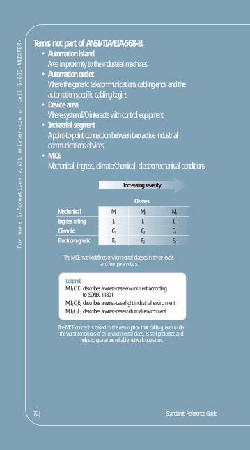
72| Standards Reference Guide
For more information, visit anixter.com or call 1.800.ANIXTER. Terms not part of ANSI/TIA/EIA-568-B:
• Automation islandArea in proximity to the industrial machines
• Automation outletWhere the generic telecommunications cabling ends and the automation-specific cabling begins
• Device areaWhere system I/O interacts with control equipment
• Industrial segmentA point-to-point connection between two active industrial communications devices
• MICEMechanical, ingress, climate/chemical, electromechanical conditions
Mechanical M1 M2 M3
Ingress rating I1 I2 I3Climatic C1 C2 C3
Electromagnetic E1 E2 E3
Classes
Increasing severity
The MICE matrix defines environmental classes in three levels and four parameters.
Legend:M1I1C1E1 describes a worst-case environment according to ISO/IEC 11801M2I2C2E2 describes a worst-case light industrial environmentM3I3C3E3 describes a worst-case industrial environment
The MICE concept is based on the assumption that cabling, even under the worst conditions of an environmental class, is still protected and
helps to guarantee reliable network operation.

Products. Technology. Services. Delivered Globally.
Section Contents
ANSI/TIA-1005Telecommunications Standard for Industrial Premises
Industrial Areas . . . . . . . . . . . . . . . . . . . . . . . . . . . . . . . . . . . . . . . . . . . . . . .74Control Equipment/Telecommunications Room . . . . . . . . . . . . . . . . . . . .74Factory Floor Area . . . . . . . . . . . . . . . . . . . . . . . . . . . . . . . . . . . . . . . . . . .74Work Area . . . . . . . . . . . . . . . . . . . . . . . . . . . . . . . . . . . . . . . . . . . . . . . . .75Automation Island Area . . . . . . . . . . . . . . . . . . . . . . . . . . . . . . . . . . . . . .75
Standards Reference Guide |73
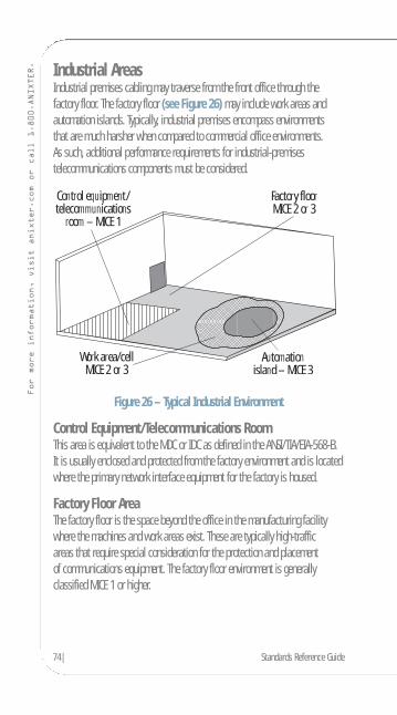
74| Standards Reference Guide
For more information, visit anixter.com or call 1.800.ANIXTER. Industrial Areas
Industrial premises cabling may traverse from the front office through thefactory floor. The factory floor (see Figure 26) may include work areas andautomation islands. Typically, industrial premises encompass environments that are much harsher when compared to commercial office environments. As such, additional performance requirements for industrial-premisestelecommunications components must be considered.
Figure 26 – Typical Industrial Environment
Control Equipment/Telecommunications Room This area is equivalent to the MDC or IDC as defined in the ANSI/TIA/EIA-568-B.It is usually enclosed and protected from the factory environment and is locatedwhere the primary network interface equipment for the factory is housed.
Factory Floor Area The factory floor is the space beyond the office in the manufacturing facilitywhere the machines and work areas exist. These are typically high-traffic areas that require special consideration for the protection and placement of communications equipment. The factory floor environment is generallyclassified MICE 1 or higher.
Control equipment/telecommunications
room – MICE 1
Automationisland – MICE 3
Factory floorMICE 2 or 3
Work area/cellMICE 2 or 3
Products. Technology. Services. Delivered Globally.
Work AreaOn a factory floor, the work area is where personnel interact with thetelecommunications devices and industrial machines. Work areas often have more severe environments than the factory floor. It is important that the work area be properly designed for both occupants and control devices. The environment of the work area is generally classified MICE 1 or higher.
Automation Island Area The automation island is the space on the factory floor in immediate proximityto or on the industrial machines and usually accompanies a work area. It isusually the most environmentally harsh area within the industrial premise.Accordingly, the automation island can often be identified as an area wherehumans are generally not present during machine cycling. In some cases, theautomation island may extend into the work area. Components selected to beinstalled need to be compatible with the environment local to the components.The industrial machines require connectivity to machine control devices such as machine sensors, vision and general telecommunications devices. The environment of the automation island is generally classified MICE 3.
Standards Reference Guide |75

76| Standards Reference Guide
For more information, visit anixter.com or call 1.800.ANIXTER.
To order a copy go toanixter.com/literature or ask your sales representative for Anixter Part No. 252181.
Anixter Standards Reference GuideTelecommunications Infrastructure for Industrial PremisesAnixter’s Standards Reference Guide for Telecommunications Infrastructurefor Industrial Premises is an invaluable tool to help you plan and installtelecommunications cabling infrastructure within and between industrialbuildings. The ANSI/TIA-1005 standard addresses the potential exposure to hostile environments in the industrial space. In addition to the specialcabling system requirements for industrial operations, including 2-paircabling systems, the standard provides definitions for areas in theindustrial space including automation islands, outlets and cables.

Products. Technology. Services. Delivered Globally.
Purpose of the ISO 11801:2002 StandardThe International Standard provides:
• Users with an application-independent generic cabling system capable of supporting a wide range of applications
• Users with a flexible cabling scheme, so modifications are both easy and economical
• Building professionals’ (architects, for example) guidance on theaccommodation of cabling at the initial stages of development.
The International Standard specifies a multimanufacturer cablingsystem that may be implemented with material from single andmultiple sources and is related to:
• International standards for cabling components developed by committees in the IEC
• Standards for the installation and operation of information technology cabling as well as for testing of installed cabling
• Applications developed by technical committees of the IEC• Planning and installation guides that account for the needs
of specific applications.
Generic cabling defined within this International Standard:• Specifies a cabling structure supporting a wide variety of applications• Specifies channel and link classes A, B, C, D and E, meeting
the requirements of standardized applications• Specifies channel and link classes E and F based on higher performance
components to support future applications• Specifies optical channel and link classes OF-300, OF-500 and OF-2000• Involves component requirements and specifies cabling implementations
that ensure performance of permanent links and channels that meet or exceed the requirements for cabling classes
The International Standard specifies a generic cabling system that is anticipatedto have a usable life in excess of 10 years.
Standards Reference Guide |77

78| Standards Reference Guide
For more information, visit anixter.com or call 1.800.ANIXTER. ISO 11801 Class EA Standard
The requirements for ISO (the International Organization for Standardization)Class EA are more demanding compared to the TIA/EIA Augmented Category 6requirements. Anixter’s Infrastructure Solutions Lab tests to the more stringentISO standards.
This table summarizes the various UTP cabling options and their respective 10 Gigabit performance attributes as defined by the latest draft standards.Category 5e is not recognized as a viable cabling media to support 10 Gigabittransmission regardless of its installed cabling distance. Category 6 cabling will only support 10 Gigabit at a maximum installed distance of 55 meters.
Today, the only options for operating 10 Gigabit at 100 meters using RJ45connectivity are the TIA Augmented Category 6 and ISO Class EA standards. ISO’s Class EA system has superior NEXT and PSNEXT performance values when compared with the current TIA Augmented Category 6 standard.
TIA Category 6 versus Augmented Category 6 versus ISO Class EATIA Category TIA Category TIA Augmented ISO Class EA5e UTP 6 UTP Category 6 UTP
Recognized by IEEE 802.3an No Yes Yes Yes55 MeterDistance Support No Yes Yes Yes100 MeterDistance Support No No Yes YesExtrapolated Test Limits for NEXTand PSNEXTto 500 MHz No No No Yes
ISO Compared to TIACharacteristics 500 MHz (dB) ISO Class EA TIA Augmented Category 6PSNEXT Loss 24.8 dB 23.2 dBNEXT Loss 27.9 dB 26.1 dBPSANEXT Loss 49.5 dB 49.5 dBReturn Loss 6.0 dB 6.0 dBInsertion Loss 49.3 dB 49.3 dBReferred to by IEEE Yes No
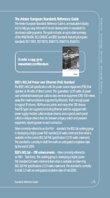
Products. Technology. Services. Delivered Globally.
The Anixter European Standards Reference GuideThe Anixter European Standards Reference Guide is an invaluable industry tool to help you stay informed of recent developments in standards forstructured cabling systems. The guide includes an up-to-date summary of the ANSI/TIA/EIA, ISO, CENELEC and IEEE standards featuring Europeanstandards ISO 11801, ISO 18010, EN50173, EN50174, EN50310.
IEEE’s 802.3af Power over Ethernet (PoE) StandardThe IEEE’s 802.3af specification calls for power source equipment (PSE) thatoperates at 48 volts of direct current. This guarantees 12.95 watts of powerover unshielded twisted-pair cable to data terminal equipment (DTE) 100 metersaway (the maximum distance supported by Ethernet). That’s enough power to support IP phones, WLAN access points and many other DTE devices. Two PSE types are supported including Ethernet switches equipped with power supply modules called endspan devices and a special patch panel called a midspan device that sits between a legacy switch and poweredequipment, injecting power to each connection.
More commonly referred to as the PoE+ standard, the 802.3at working groupis developing a higher power PoE standard (24 watts minimum) than what isavailable on the current 802.3af PoE specification (12.95 watts maximum). The standard is currently in draft form with an anticipated completion date by the end of 2009.
IEEE’s 802.3at – DTE enhancements – More commonly referred to as PoE+ Task Force. This working group is developing a higher power PoE standard (24 watts minimum) than what is available on token ring 802.3af PoE specifications (12.9 watts maximum). The standard is currently in draft 3.3 with an anticipated completion date of mid-2009.
To order a copy, go towww.anixter.com/literature.
Standards Reference Guide |79
80| Standards Reference Guide
For more information, visit anixter.com or call 1.800.ANIXTER. IEEE’s 802.11 Wireless Standards
IEEE 802.11, the Wi-Fi standard, denotes a set of wireless LAN/WLAN standardsdeveloped by working group 11 of the IEEE LAN/MAN standards committee (IEEE 802). The term 802.11x is also used to denote this set of standards and is not to be mistaken for any one of its elements. There is no single 802.11x standard.
802.11 details a wireless interface between devices to manage packet traffic (to avoid collisions, etc.). Some common specifications and their distinctiveattributes include the following:
802.11a – Operates in the 5 GHz frequency range (5.125 to 5.85 GHz) with a maximum 54 Mbps signaling rate. The 5 GHz frequency band isn’t as crowded as the 2.4 GHz frequency because it offers significantly moreradio channels than the 802.11b and is used by fewer applications. It has a shorter range than 802.11g, is actually newer than 802.11b and is notcompatible with 802.11b. 802.11b – Operates in the 2.4 GHz Industrial, Scientific and Medical (ISM)band (2.4 to 2.4835 GHz) and provides signaling rates of up to 11 Mbps.This is a very commonly used frequency. Microwave ovens, cordless phones,medical and scientific equipment, as well as Bluetooth® devices, all workwithin the 2.4 GHz ISM band. 802.11e – Ratified by the IEEE in late September 2005, the 802.11e quality-of-service specification is designed to guarantee the quality of voiceand video traffic. It will be particularly important for companies interested in using Wi-Fi phones.802.11g – Similar to 802.11b, this standard supports signaling rates of up to 54 Mbps. It also operates in the heavily used 2.4 GHz ISM band butuses a different radio technology to boost overall throughput. Compatiblewith older 802.11b.802.11i – Also sometimes called Wi-Fi Protected Access 2 (WPA 2), 802.11i was ratified in June 2004. WPA 2 supports the 128-bit-and-aboveAdvanced Encryption Standard, along with 802.1x authentication and keymanagement features.
Products. Technology. Services. Delivered Globally.
802.11k – Passed in June 2008, the 802.11k Radio Resource ManagementStandard will provide measurement information for access points andswitches to make wireless LANs run more efficiently. It may, for example,better distribute traffic loads across access points or allow dynamicadjustments of transmission power to minimize interference.802.11n – 802.11n is a set of standards for wireless local area network(WLAN) computer communications developed by the IEEE LAN/MANStandards Committee (IEEE 802) in the 5 GHz and 2.4 GHz public spectrumbands. The proposed amendment improves upon the previous 802.11standards by adding multiple-input, multiple-output (MIMO) and many othernewer features. The working group is not expected to finalize the amendmentuntil December 2009.
Standards Reference Guide |81
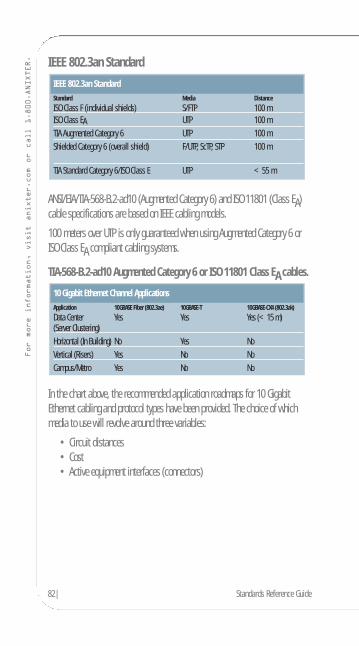
82| Standards Reference Guide
For more information, visit anixter.com or call 1.800.ANIXTER. IEEE 802.3an Standard
ANSI/EIA/TIA-568-B.2-ad10 (Augmented Category 6) and ISO 11801 (Class EA)cable specifications are based on IEEE cabling models.
100 meters over UTP is only guaranteed when using Augmented Category 6 orISO Class EA compliant cabling systems.
TIA-568-B.2-ad10 Augmented Category 6 or ISO 11801 Class EA cables.
In the chart above, the recommended application roadmaps for 10 GigabitEthernet cabling and protocol types have been provided. The choice of whichmedia to use will revolve around three variables:
• Circuit distances• Cost• Active equipment interfaces (connectors)
10 Gigabit Ethernet Channel ApplicationsApplication 10GBASE Fiber (802.3ae) 10GBASE-T 10GBASE-CX4 (802.3ak)
Data Center Yes Yes Yes (<15 m)(Server Clustering)Horizontal (In Building) No Yes NoVertical (Risers) Yes No NoCampus/Metro Yes No No
IEEE 802.3an StandardStandard Media Distance
ISO Class F (individual shields) S/FTP 100 mISO Class EA UTP 100 mTIA Augmented Category 6 UTP 100 mShielded Category 6 (overall shield) F/UTP, ScTP, STP 100 m
TIA Standard Category 6/ISO Class E UTP <55 m
Products. Technology. Services. Delivered Globally.
10GBASE fiber will maintain traditional application in backbones and risers and also in the data center for server clustering.
10GBASE-T copper will remain in the traditional areas of application (in horizontal building cabling but also in the data center between servers and clusters).
10GBASE-CX4 defines a multiconductor copper solution primarily designed to connect servers and switches over short distances.
802.3ba – 40 Gbps and 100 Gbps Ethernet – The purpose of this project is to extend the 802.3 protocol to operating speeds of 40 Gbps and 100 Gbps in order to provide a significant increase in bandwidth while maintainingcompatibility with the installed base of 802.3 interfaces, previous investment in research and development, and principles of network operation andmanagement. Anticipated completed date for all working groups is 2011.
Standards Reference Guide |83
84| Standards Reference Guide
For more information, visit anixter.com or call 1.800.ANIXTER. The Anixter Infrastructure Solutions Lab
Anixter’s Infrastructure Solutions Lab actively demonstrates the best practicaltechnology solutions from best-in-class manufacturers in the area of enterprisecabling, video security and access control for our customers. Our mission forThe Lab is simple—educate, demonstrate and evaluate.
• Educate customers on the latest industry standards and technologies• Demonstrate the latest infrastructure product solutions available from
our manufacturer partners• Evaluate our network infrastructure and security solutions to ensure that
our customers are selecting the right products for their specific needs
We are continually testing products in our Lab to ensure:• Quality products are recommended and delivered to our customers• Consistency of performance across product lines and within systems• Interoperability of products and systems to ensure customers can
integrate systems and follow the trend toward convergence.
Products. Technology. Services. Delivered Globally.
Networking and Security Product Testing at Our Lab Includes: • Random performance testing of Anixter inventory to ensure quality
of standards compliance• Network throughput and interoperability testing• Copper and fiber cabling compliance verification (TIA/EIA, ISO/IEC, IEEE)• Customer proof of concept• Power over Ethernet (PoE)• Application testing• 10 Gig Ethernet cabling testing• Video over IP, video quality and bandwidth utilization• Power over Ethernet capability and verification• Digital compression image quality vs. analog technology testing• Evaluation of analog and IP cameras, video management software
evaluation, DVR, NDVR and NVR products.
Standards Reference Guide |85
86| Standards Reference Guide
For more information, visit anixter.com or call 1.800.ANIXTER. Anixter’s Infrastructure Solutions Lab In Action
Problem: Leading Pennsylvania University Explores CampuswideRewiring ProjectAnixter Infrastructure Solutions Lab Resolution: The Anixter InfrastructureSolutions Lab was called upon to help this university determine which coppercabling system would best meet its current and future information technologyneeds. The university had a variety of different copper cabling products installedin its network infrastructure: Category 3, Category 5 and some Category 5e. The Anixter Infrastructure Solutions Lab deployed computer applications that the university typically carried over its cabling infrastructure, including LotusNotes, SAP and streaming video. Testing found that its current infrastructure was consistently dropping information, causing the network to operate slowlyand inefficiently. This same traffic was sent over a Category 6 infrastructure withno degradation to the data. Armed with testing from the Anixter InfrastructureSolutions Lab, university IT professionals wrote cabling infrastructurespecifications around a higher performing Category 6 system that better met the university’s network performance needs.
Products. Technology. Services. Delivered Globally.
Problem: Major Railway Company Needs Video Surveillance To Monitor SwitchyardAnixter Infrastructure Solutions Lab Resolution: A railroad company wantedto use video surveillance to monitor its yards as workers assembled unit trains,but it had a big cabling challenge. Installing traditional cabling in the switchyardwould have entailed major disruptions and expense for the customer. Instead,Anixter’s Infrastructure Solutions Lab recommended a sophisticated wirelessInternet video surveillance system that did not require cabling. Anixter was ableto simulate the wireless Internet video surveillance solution in the InfrastructureSolutions Lab for the customer. The Infrastructure Solutions Lab also providedthis customer with test results illustrating how much bandwidth the videosolution would absorb on the customer’s network as well as the video qualitythe customer could expect from the recommended system.
Problem: National Insurance Company with Data Center Cabling ChoiceAnixter Infrastructure Solutions Lab Resolution: The Anixter InfrastructureSolutions Lab assessed backbone cabling requirements based on the currentand future bandwidth needs for this insurance provider. The AnixterInfrastructure Solutions Lab ran representative network traffic over 62.5-micron, 50-micron and laser-optimized 50-micron fiber (OM3) to ascertainwhich would best meet the company’s needs. These tests were key indetermining that the OM3 was the customer’s best choice.
Standards Reference Guide |87

88| Standards Reference Guide
For more information, visit anixter.com or call 1.800.ANIXTER. Anixter’s 10 Gigabit Ethernet Cabling Testing
Anixter Infrastructure Solutions Lab is the only UL Certified lab to conductrigorous, independent third-party testing of emerging 10 Gigabit cablingsolutions. Anixter’s 10 Gigabit cabling testing examines electrical characteristicssuch as insertion loss, return loss and crosstalk, but also looks at aliencrosstalk (which is part of the Augmented Category 6 spec). To ensure that the 10 Gigabit cabling solutions we sell meet the highest levels of performanceand reliability for our customers, the Anixter Infrastructure Solutions Lab tests the toughest performance parameter, alien crosstalk, in a “worst case”scenario. Customers can rest assured that the cabling solutions Anixter sells will provide the network performance they require.

Products. Technology. Services. Delivered Globally.
Standards Reference Guide |89
90| Standards Reference Guide
For more information, visit anixter.com or call 1.800.ANIXTER. Reference Documents for Further Information
on Cabling StandardsTIA/EIA-568-B.1 (2001)
Commercial Building Telecommunications Cabling Standard Part 1: General Requirements
TIA/EIA-568-B.2 (2001)Commercial Building Telecommunications CablingStandard Part 2: Balanced Twisted-Pair Cabling Components
TIA/EIA-568-B.2-1 (2002)Transmission Performance Specifications for 4-pair 100ΩAugmented Category 6 Cabling
TIA/EIA-568-B.2-ad10 (2008)Transmission Performance Specifications for 4-pair 100ΩAugmented Category 6 Cabling
TIA/EIA-568-B.3 (2000)Optical Fiber Cabling Components Standard
TIA/EIA-569-B (2004) (CSA T530)*Commercial Building Standard for Telecommunications Pathways and Spaces
TIA/EIA-570-A (1999) (CSA T525)*Residential and Light Commercial Telecommunication Wiring Standard
TIA/EIA-606-A (2002) (CSA T528)*Administration Standard for the Telecommunications Infrastructure of Commercial Buildings
J-STD-607-A (2002) (CSA T527)*Commercial Building Grounding/Bonding Requirements forTelecommunications
*Canadian Standards Association equivalent document
Products. Technology. Services. Delivered Globally.
TIA/EIA-758 (1999)Customer-Owned Outside Plant Telecommunications Cabling Standard
TIA/EIA-942 (2005)Telecommunications Infrastructure Standard for Data Centers
ANSI/TIA-1005 (Draft)Telecommunications Infrastructure for Industrial Premises
IS0/IEC 11801 (2002)Generic Cabling for Customer Premises
IEEE 802.3-1998 (1998)Carrier Sense Multiple Access with Collision Detection (CSMA/CD) Access Method and Physical Layer Specification (also known as ANSI/IEEE Std 802.3-1998 or ISO 8802-3: 1990 (E))
IEEE 802.3an (2006)Physical Layer and Management Parameters for 10 Gbps Operation, Type 10GBASE-T
IEEE 802.5-1998 (1998)Token Ring Access Method and Physical Layer Specifications (also known as ANSI/IEEE Std 802.5-1998)
Standards Reference Guide |91

92| Standards Reference Guide
For more information, visit anixter.com or call 1.800.ANIXTER. Obtaining Standards Documents
TIA/EIA documents may be purchased through Global Engineering Documents at (800) 854-7179 or www.global.ihs.com. IEEE documents may be purchasedthrough IEEE, P.O. Box 1331, Piscataway, NJ 08855 or www.ieee.org. CSAdocuments may be purchased through the Canadian Standards Association at www.csa.ca or by calling (416) 747-4000.
For further assistance or more information, contact your local Anixter salesoffice or 1.800.ANIXTER. Some material in this publication is reproduced from standards publications, which are copyrighted by the TelecommunicationsIndustry Association.
This guide was prepared by Anixter, which is not affiliated with theTelecommunications Industry Association or the Electronic Industries Alliance.Neither EIA nor TIA are responsible for the content of this publication.
For direct assistance in interpreting telecommunications standards, considerRegistered Communications Distribution Designers (RCDD) certified by theBuilding Industry Consulting Service International (BICSI) at (800) 242-7405 or www.bicsi.org. Hundreds of Anixter technical professionals are registered with BICSI.

The Anixter European Standards Reference GuideThe Anixter European Standards Reference Guide is an invaluableindustry tool to help you stay informed of recent standarddevelopments for structured cabling systems. The guide includes an up-to-date summary of the ANSI/TIA/EIA, ISO,CENELEC and IEEE standards featuring European standards ISO 11801, ISO 18010, EN50173, EN50174, EN50310. To order a copy, go to www.anixter.com/literature.

9H00
06X0
© 20
09 An
ixter
Inc. •
05/0
9 • 3K
• 25
1937
Aerospace Hardware • Electrical and Electronic Wire & CableEnterprise Cabling & Security Solutions • Fasteners
Anixter Inc. • 1.800.ANIXTER • anixter.com • World Headquarters:2301 Patriot Boulevard, Glenview, IL 60026-8020 • 224.521.8000
Anixter is a leading global supplier of communications and security products, electrical and electronic wire and cable, fasteners and other small components. We help our customers specify solutions and make informed purchasing decisions around technology, applications
and relevant standards. Throughout the world, we provide innovative supply chain management services to reduce our customers’ total cost of production and implementation.
A NYSE listed company, Anixter, with its subsidiaries, serves companies in more than 52 countries around the world. Anixter’s total revenue exceeded $6.1 billion in 2008.
Anixter Inc. does not manufacture the items described in this publication. All applicable warranties are provided by the manufacturers. Purchasers are requested to determine directly from the manufacturers
the applicable product warranties and limitations.Data and suggestions made in the publication are not to be construed as recommendations or authorizations to use any products in violation
of any government law or regulation relating to any material or its use.