standards for hydrographic surveys within queensland waters
TRANSCRIPT
Standards for Hydrographic Surveys within Queensland Waters
Branch Spatial Services and Information Section
Division Maritime Safety Queensland
Location Floor 21 Mineral House, Brisbane, 4001.
Version No. 1.3
Revision Date 06/01/09
Status Updated January 2009
DMS ref no.
Standards for Hydrographic Surveys within Queensland Waters Revision 1.3 Date Issued 6th February 2009
Table of Contents SCOPE ................................................................................................................................. 1
FOREWORD ......................................................................................................................... 2
PART ONE STANDARDS 1 INTRODUCTION .......................................................................................................... 5
1.1 Mandatory Requirements ..................................................................................... 5
1.2 Guidelines for Managers ...................................................................................... 5
1.3 Guidelines for Hydrographic Surveyors ................................................................ 6
2 PERSONNEL ............................................................................................................... 6
3 SURVEY INTERVAL .................................................................................................... 6
4 SURVEY METHODOLOGY .......................................................................................... 6
5 SURVEY CLASS .......................................................................................................... 6
5.1 Class A survey classification ................................................................................ 7
5.2 Class B survey classification ................................................................................ 8
5.3 Class C survey classification ................................................................................ 8
5.4 Class D survey classification ................................................................................ 9
6 NAVIGABLE DEPTH .................................................................................................... 9
7 ENDORSEMENTS ......................................................................................................10
PART TWO MANDATORY REQUIREMENTS 1 INTRODUCTION ...........................................................................................................13
2 PERSONNEL ................................................................................................................13
2.1 Certification as a Hydrographic Surveyor ............................................................13
2.2 Responsibilities ...................................................................................................13
2.3 Training/Job Instructions .....................................................................................14
3 HORIZONTAL AND VERTICAL DATUM'S ....................................................................14
3.1 Horizontal Datum ................................................................................................14
3.2 Vertical Datum ....................................................................................................14
4 METHOD STATEMENT ................................................................................................15
4.1 Horizontal Positioning .........................................................................................15
4.2 Vertical Datum ....................................................................................................15
4.3 Depth Measurement............................................................................................15
4.4 Seabed Coverage ...............................................................................................15
4.5 Sounding Reduction and Data Presentation ........................................................16
4.6 Data Quality and Retention .................................................................................16
5 MANDATORY REPORTING REQUIREMENT ..............................................................16
6 SURVEY REPORT ........................................................................................................17
Standards for Hydrographic Surveys within Queensland Waters Revision 1.3 Date Issued 6th February 2009
7 SURVEY PLAN .............................................................................................................17
8 CURRENCY OF DATA..................................................................................................18
9 STATISTICAL ANALYSIS .............................................................................................18
PART THREE GUIDELINES FOR MANAGERS 1 INTRODUCTION .........................................................................................................20
2 SURVEY CLASSIFICATION ........................................................................................20
3 DETERMINING A CLASS OF HYDROGRAPHIC SURVEY ........................................22
3.1 Consequence Matrix ...........................................................................................22
3.2 Likelihood Matrix .................................................................................................22
3.3 Survey Class Matrix ............................................................................................22
4 MINIMUM QUALIFICATION OF PERSONNEL ............................................................26
4.1 Phase in Period for Hydrographic Surveying Competencies ...............................26
5 SURVEY INTERVAL ...................................................................................................26
5.1 Survey Interval Criteria ........................................................................................26
5.2 Survey Interval Schedule ....................................................................................31
6 FUTURE AUDIT OF STANDARDS ..............................................................................32
PART FOUR GUIDELINES FOR HYDROGRAPHIC SURVEYORS 1 INTRODUCTION .........................................................................................................35
2 PROJECT INSTRUCTION ...........................................................................................35
3 HORIZONTAL DATUM ................................................................................................35
3.1 Control Points .....................................................................................................35
4 VERTICAL DATUM .....................................................................................................36
4.1 Real Time Kinematic (RTK) GPS ........................................................................36
4.2 Clearance Heights ..............................................................................................36
4.3 Sources of additional information ........................................................................36
5 EQUIPMENT CALIBRATION/CERTIFICATION ...........................................................36
6 HORIZONTAL POSITIONING .....................................................................................36
6.1 Horizontal Tolerance ...........................................................................................36
6.2 Position Checks ..................................................................................................37
6.3 Rejection Criteria ................................................................................................37
7 TIDE GAUGES ............................................................................................................37
7.1 Automatic Tide Gauges .......................................................................................37
7.2 Tide Boards ........................................................................................................37
7.3 Water Level Checks ............................................................................................38
8 DEPTH MEASUREMENT ............................................................................................38
8.1 Vessel Squat .......................................................................................................38
Standards for Hydrographic Surveys within Queensland Waters Revision 1.3 Date Issued 6th February 2009

8.2 Transducer Motion (Heave) .................................................................................38
8.3 Single Beam Echo Sounder (SBES) ...................................................................38
8.4 Multi-Beam Echo Sounder (MBES) .....................................................................39
8.5 Physical (Leadline/Sounding Pole) ......................................................................39
9 SEABED COVERAGE .................................................................................................39
9.1 Across Track .......................................................................................................40
9.2 Along Track .........................................................................................................40
9.3 Sweep System ....................................................................................................40
9.4 Line Spacing and Design ....................................................................................41
10 SOUNDING REDUCTION ...........................................................................................41
10.1 Vertical ................................................................................................................41
10.2 Tidal Predictions .................................................................................................42
10.3 Sounding Reduction by AUSHYDROID ...............................................................42
11 PRELIMINARY DATA PRESENTATION .....................................................................42
12 DATA PRESENTATION ..............................................................................................42
12.1 Key Depths .........................................................................................................43
12.2 Compiled Data ....................................................................................................43
12.3 Contours .............................................................................................................43
13 DATA QUALITY ...........................................................................................................43
14 DATA RETENTION .....................................................................................................43
15 SURVEY PLAN ...........................................................................................................43
15.1 Scale ...................................................................................................................43
16 GLOSSARY .................................................................................................................45
17 REFERENCES AND SELECTED BIBLIOGRAPHY .....................................................47
APPENDIX 1 METHOD STATEMENT ............................................................................48
APPENDIX 2 METHOD STATEMENT EXAMPLE ...........................................................52
APPENDIX 3 SURVEY REPORT ....................................................................................56
Standards for Hydrographic Surveys within Queensland Waters Revision 1.3 Date Issued 6th February 2009
SCOPE
These "Standards for Hydrographic Surveys within Queensland Waters" have been prepared by Maritime Safety Queensland in consultation with all Queensland Port Authorities. They are designed to ensure that all users select the survey class, survey interval and personnel required to guarantee that the declared depth may be confidently used by Maritime Safety Queensland and the Port Authorities to effectively and safely manage the ports and waterways of Queensland. These are minimum performance standards that apply to all hydrographic surveys of Queensland waters. There are four parts:
Part One - Standards Part Two - Mandatory Requirements; Part Three - Guidelines for Managers ; and Part Four - Guidelines for Hydrographic Surveyors.
Compliance with parts one and two is obligatory. Parts three and four give guidance but do not provide a step by step manual on how to carry out any particular survey. Note: - The meaning and usage of words in italics are detailed in the Glossary. The
words 'shall' and 'must' are to be read as mandatory. 'Should' and 'may' are to be read as discretionary.
Standards for Hydrographic Surveys Within Queensland Waters Revision 1.2 Page 1 of 63 Date Issued 31 May 2007
FOREWORD
The accuracy of the charted depths is a significant component of a port's under keel clearance and the cost of the hydrographic surveys made to obtain those depths is high. There has been increasing pressure on Port Authorities and government to be able to justify, or in some cases, defend the magnitude of the under keel clearance that must be maintained by a ship transiting a port and the cost of the hydrographic surveys. Most ports have dredged channels, berths and anchorages. This infrastructure suffers from siltation which reduces the depth available to shipping. Because the ports operate with a minimum under keel clearance regular surveys are required in order to monitor the depth. All hydrographic survey data bears some degree of uncertainty (survey/charted depth tolerance) which is related to numerous factors including survey equipment used, environmental conditions, etc. These Queensland standards have been prepared to ensure that charted depths are accurate and that the charted depth tolerance is commensurate with the allowance provided in the under keel clearance for the port. To that end the standards:-
• Supplement the International Hydrographic Organization (IHO) Special Publication S44 (Standards for Hydrographic Surveys), and,
• Are based on the "Principles for Gathering and Processing Hydrographic Information
in Australian Ports" prepared by the Hydrographic Surveyors Working Group of the Association of Australian Port and Marine Authorities (AAPMA) and accepted by the association as guidelines applicable to hydrography in Australian ports.
The International Hydrographic Organisation (IHO) Publication S44 provides the minimum international standards for hydrographic surveys. It also requires that hydrographic surveyors strive to attribute their survey data with a statistical estimate of its probable error. Similarly these Queensland standards require the statistical estimation of the survey depth tolerance given the methodologies and equipment documented in the method statement and used to perform the survey. The method statement is unique to each survey. Part one of these standards introduces the standard by outlining the:
• Mandatory requirements
• Guidelines to managers and hydrographic surveyors
• Personnel who may conduct the survey
• Frequency at which surveys are undertake
• Methodologies to be used in the survey
• Survey classification scheme
• Definition of navigable depth; and,
• Phase in period for hydrographic surveying competencies.
Part Two of these standards set out the mandatory requirements for each class of survey. The requirements must be addressed in the method statement and must be complied with during execution of the survey. They extend from the planning stage through the data collection and presentation, to data retention. Standards for Hydrographic Surveys Within Queensland Waters Revision 1.2 Page 2 of 63 Date Issued 31 May 2007
Parts Three and Four provide guidance to managers (Part three) and hydrographic surveyors (Part four) in the application of these standards. These parts also address the issues of data currency, and fitness for the intended purpose. The professional expertise of the hydrographic surveyor is a critical element in the achievement of the aim of these standards. Surveys conforming to these standards will provide charted depths that are reliable and which can be used to effectively and safely manage the ports and waterways of Queensland.
Standards for Hydrographic Surveys Within Queensland Waters Revision 1.2 Page 3 of 63 Date Issued 31 May 2007
PART ONE STANDARDS
Part One Standards Revision 1.2 Page 4 of 63 Date Issued 31 May 2007
1 INTRODUCTION
The "Standards and Guidelines for Hydrographic Surveys within Queensland Waters" (the Standard) will assist the Regional Harbour Masters and Queensland Port Authorities to:
• Make management decisions (such as requirements for dredging, establishment of Under Keel Clearance (UKC) and declaration of port depth) with greater certainty and support.
• Interpret the hydrographic survey information received in terms of accuracy,
reliability, validity and currency.
• Identify the class of survey required for a particular purpose (and, consequently, to what technical standard), based upon an assessment of risk to the safe movement of vessels.
• Establish the level of competency required for the conduct of a particular class of
hydrographic survey.
• Determine the interval required for that survey.
1.1 Mandatory Requirements
The Mandatory Requirements:
• Set out what points must be addressed for a survey to be classed A, B, C or D;
• Set out what points must be addressed in carrying out the survey from planning through to data presentation and retention;
• Set out what points must be addressed in the Method Statement.; and
• Provides a checklist for evaluating the quality of the information provided.
• Set out the obligations of the Hydrographic Surveyor before leaving site.
1.2 Guidelines for Managers
The Guidelines for Managers:
• Details how to determine a class of survey through a risk assessment process;
• Provides information on risk assessment matrices;
• Provides the minimum qualification of personnel undertaking or supervising a Hydrographic Survey: and
• Provides information and documentation to determine the survey interval for any
area.
Part One Standards Revision 1.2 Page 5 of 63 Date Issued 31 May 2007
1.3 Guidelines for Hydrographic Surveyors
The Guidelines for Hydrographic Surveyors:
• Provides 'best practice' advice for hydrographic surveyors to achieve a particular class of survey; and
• Provides 'best practice' advice for planning a project and developing a Method
Statement.
2 PERSONNEL
The hydrographic survey and other associated tasks shall be carried out by, or directly supervised by, a hydrographic surveyor. The resulting information shall be certified by this person and shall state the class to which the information will be assigned
3 SURVEY INTERVAL
The Regional Harbour Master who declares the depth available for navigation shall develop with the port manager an agreed survey interval for the supply of information as well as the required quality and class of that information, notwithstanding ad-hoc requirements or those highlighted in clause 5.1.1. The same rationale applies to recreational Small Craft Facilities. To assist with this a Survey Interval Schedule (Refer to Part Three) has been developed to derive a consistent methodology to determine at what interval ports and recreational Small Craft Facilities are required to be surveyed. A survey of the relevant class must be undertaken, as a minimum, within the timing requirements of the Survey Interval document
4 SURVEY METHODOLOGY
It is mandatory that the hydrographic surveyor develop and document a 'Method Statement' that can clearly demonstrate that the Standard is adhered to for each hydrographic survey area. The 'Method Statement' shall, as a minimum, address all of the elements of the Mandatory Requirements.
5 SURVEY CLASS
These Standards assist with determining the appropriate criteria for a survey according to an assessment of risk relative to the safe movement of vessels. There are four classes of survey, A, B, C and D which have been created to cater for a wide range of client requirements. The Classification Table (Page 21) provides criteria for each class of hydrographic survey on:
• Depth tolerance;
• Minimum seabed coverage; and
• Minimum qualifications of personnel conducting the survey.
Part One Standards Revision 1.2 Page 6 of 63 Date Issued 31 May 2007
Survey classes A and B in these Standards are equivalent to the survey classes A and B as described in the "Principles for Gathering and Processing Hydrographic Information in Australian Ports" (AAPMA). The depth tolerance for both classes is the same. It is a requirement of that a Class A survey is undertaken using a survey method which ensures that the minimum depth within the channel toe lines (or survey area) has been defined. The requirement that minimum depth be defined is relaxed for Class B surveys. They are undertaken as check surveys of areas where a class A survey has been previously carried out. The requirements are further relaxed for Class C and D surveys. These classes are created to cover hydrographic surveys that are necessary for the safe movement of vessels in Queensland waters but that UKC is not involved. The definition of survey classes (A, B, C and D) should not be confused with 'Zone of Confidence (ZOC)' classifications as used on AUS charts produced by the Royal Australian Navy Hydrographic Office. A risk assessment is not required in areas where the Ports Procedures Manual defines Under Keel Clearance (UKC). In these areas a Class A or B survey is mandatory. Where discrepancies exist between this Standard and the International Hydrographic Office Publication S44, this Standard is to prevail.
5.1 Class A survey classification
5.1.1 Application
Class A surveys are required for but not limited to: • Investigations of an area for a proposed new channel, anchorage, berth, swing basin,
and so on, the outcome of which will be the gazetted declaration of a navigable depth.
• Increasing the declared depth in a channel, or berth area, or following maintenance,
or development dredging, or bed levelling. • Investigating a grounding or reported shoaling in an area. A survey is not a Class A survey unless it meets all of the requirements of this class.
5.1.2 Requirements
For survey information to satisfy this class the following shall be met:
• The method or methods used to undertake the hydrographic survey within the waterway shall ensure that the minimum depth in the navigable waterway has been determined.
• The resultant reduced depths shall have a survey depth tolerance equal to or better
than the survey tolerance in the port's UKC formula. In all other cases the survey depth tolerance shall be equal to or better than depth tolerance stated in the Classification Table.
Part One Standards Revision 1.2 Page 7 of 63 Date Issued 31 May 2007
5.2 Class B survey classification
5.2.1 Application
Class B surveys are required for but not limited to: • Check or depth maintenance surveys. The information should be of sufficient
quantity and quality that allows the relevant Regional Harbour Master to amend the declared depth if necessary.
• Initial investigations of any events that may have caused abnormal changes in the
seabed. These are to be followed by class A surveys in areas where deemed necessary.
A survey is not a Class B survey unless it meets all of the requirements of this class.
5.2.2 Requirements
For survey information to satisfy this class the following shall be met:
• A class A survey has previously been carried out in the surveyed area and in the opinion of the Regional Harbour Master an obstruction to navigation is not expected.
• Depth data shall be collected from a minimum of 20 percent of the seabed in the
navigable waterway. Spacing of sounding lines shall meet this requirement and may be of closer spacing in areas where siltation is known to occur. However the area coverage shall be negotiated between the Regional Harbour Master and the hydrographic surveyor and, where applicable, the Port Authority.
• The resultant depths shall have a survey depth tolerance equal to or better than the
survey tolerance in the port's UKC formula. In all other cases the survey depth tolerance shall be equal to or better than depth tolerance stated in the Classification Table.
5.3 Class C survey classification
5.3.1 Application
Class C surveys are required for but not limited to: • Navigation requirements for Small Craft Facilities such as boat harbours, channels,
navigable rivers and creeks. In these instances UKC does not apply.
• Management of Aids to Navigation
A survey is not a Class C survey unless it meets all of the requirements of this class.
5.3.2 Requirements
For survey information to satisfy this class the following shall be met:
Part One Standards Revision 1.2 Page 8 of 63 Date Issued 31 May 2007
• Depth data shall be collected from a minimum of 20 percent of the seabed in the survey area. Spacing of sounding lines shall meet this requirement and may be of closer spacing in areas where siltation is known to occur. For surveys in less than 5 metres of water the nominal line spacing is to be 5 metres. Depending on the purpose of the hydrographic survey the area coverage can be negotiated between the client and the hydrographic surveyor.
• The resultant depths shall have a survey depth tolerance equal to or better than
depth tolerance stated in the Classification Table.
• The information shall be of sufficient quantity and quality that enables the safe and effective management of Queensland Small Craft Facilities and Aids to Navigation.
5.4 Class D survey classification
5.4.1 Application
Class D surveys are required for but not limited to: • Surveys for small craft charts, boat ramps and coastal engineering requirements
such as beach profiles of the Beach Protection Agency (BPA).
A survey is not a Class D survey unless it meets all of the requirements of this class.
5.4.2 Requirements
For survey information to satisfy this class the following shall be met:
• The nominal spacing of survey lines is 3 x average water depth or 25 metres whichever is greater. Spacing of sounding lines shall meet this requirement and may be of closer spacing in areas where siltation is known to occur or closer spacing is required to adequately delineate a shoal, contour or seabed feature. Depending on the purpose of the hydrographic survey the area coverage can be negotiated between the client and the hydrographic surveyor. For example, for BPA profiles the line spacings have been pre-determined and are required to be re-surveyed in the same positions.
• The resultant depths shall have a survey depth tolerance equal to or better than the
depth tolerance stated in the Classification Table.
• The information shall be of sufficient quantity and quality that enables the safe and effective management of Queensland Waterways.
6 NAVIGABLE DEPTH
For Queensland Waters the navigable seabed is defined as being the trace produced by a 200 KHz (or higher frequency) transducer. As such the navigable depth is defined as being the minimum return as determined by the hydrographic surveyor from a 200 KHz (or higher frequency) transducer or where a dual frequency echo sounder is used the minimum determined depth from either frequency providing one frequency is 200 KHz or higher.
Part One Standards Revision 1.2 Page 9 of 63 Date Issued 31 May 2007
7 ENDORSEMENTS
The Standard has been endorsed by: Maritime Safety Queensland; [Transport Infrastructure Branch]; [Bundaberg Port Authority]; [Cairns Port Authority]; [Central Queensland Ports Authority]; [Mackay Port Authority]; [Ports Corporation of Queensland]; [Port of Brisbane Corporation]; and [Townsville Port Authority]
Part One Standards Revision 1.2 Page 10 of 63 Date Issued 31 May 2007
This Page Intentionally Blank
Part One Standards Revision 1.2 Page 11 of 63 Date Issued 31 May 2007
PART TWO MANDATORY REQUIREMENTS
Part Two Mandatory Requirements Revision 1.2 Page 12 of 63 Date Issued 31 May 2007
1 INTRODUCTION
The purpose of Part Two (Mandatory Requirements) is to provide the user and the supplier of hydrographic information for Queensland Waters with a check list for evaluating the quality of the information provided and for use in the initial planning of a survey. It does not provide detailed technical aspects, however it does set out what points must be addressed for a survey to be classed A, B, C or D. The Method Statement (Section 4) is critical in demonstrating that the required Standards can be achieved. As such the purpose of the Method Statement is to clearly state how the Mandatory Requirements will be met. The technical aspects that are to be included in the Method Statement are the responsibility of a certified hydrographic surveyor. Part Two is also useful as a guide in the preparation of a detailed technical specification for inclusion in contract documents. The user of Part Two should have a strong working knowledge of hydrographic surveying or have access to professional advice on this matter. Hydrographic surveying relies on information from a number of sensors and is a form of remote sensing. As such the hydrographic surveyor must ensure that equipment is kept in calibration and demonstrate that it meets the accuracy requirements of the hydrographic survey.
2 PERSONNEL
2.1 Certification as a Hydrographic Surveyor
The hydrographic surveyor responsible for the hydrographic information as described in Part One Section 2 of these Standards shall be a Certified Practitioner (Hydrography 1 or 2) as determined by the Australasian Hydrographic Surveyors Certification Panel of the Spatial Sciences Institute of Australia. For those persons undertaking hydrographic surveys within Queensland Waters but not currently having the minimum qualifications of this standard, see Part Three, Guidelines for Managers, Section 4 (page 26) regarding the phase in period for Hydrographic Surveying Competencies.
2.2 Responsibilities
The hydrographic surveyor with the qualifications required in the Classification Table must accept responsibility for the hydrographic survey. This responsibility must be acknowledged by the hydrographic surveyor by signing the plan of the hydrographic survey. The Regional Harbour Master is ultimately responsible for the safe operation of vessel movements and requires accurate and timely survey data to achieve this. While maintaining a responsibility to the client, hydrographic surveyors have a mandatory responsibility to supply preliminary confirmation of Class A and B survey results to the Regional Harbour Master prior to departure from site. The hydrographic surveyor is required to report any shoal areas to the RHM promptly as they may effect the safe vessel movements and UKC for ships using the port.
Part Two Mandatory Requirements Revision 1.2 Page 13 of 63 Date Issued 31 May 2007
2.3 Training/Job Instructions
Suitable training and documented job instructions shall be provided where persons other than the hydrographic surveyor (2.1 above) carry out tasks that are critical to the resultant tolerance of the survey. The Project Instruction will assist the hydrographic surveyor in generating the Method Statement and ensure the correct area is surveyed to the required class. At a minimum the Project Instruction shall contain information on the;
Purpose of the survey
Estimated commencement and completion times
Survey requirements for each area including declared depths and key depths
References to previous surveys in that area
Positioning control and datum's to be used
Output formats and timeline for delivery
3 HORIZONTAL AND VERTICAL DATUM'S
3.1 Horizontal Datum
The horizontal datum for all hydrographic surveys carried out within Queensland Waters is to be the Geocentric Datum of Australia 94 (GDA 94). The survey shall be traceable to the Australian National Network (ANN).
3.1.1 Horizontal tolerance
The minimum horizontal tolerance shall be 1 metre ±1.5 metre at the 2 standard deviation level.
3.2 Vertical Datum
3.2.1 Class A and B Surveys
The survey shall be connected to the port's 'standard port' bench mark. Soundings shall be reduced to chart datum as defined by Maritime Safety Queensland (refer Maritime Safety Queensland document on co-tidal information for Queensland Waters).
3.2.2 Class C and D Surveys
The survey shall be connected to the nearest standard bench mark. Soundings should be reduced to chart datum as defined by Maritime Safety Queensland (refer Maritime Safety Queensland document on co-tidal information for Queensland Waters) unless another datum (eg. AHD) is required to be used for a specific engineering purpose. If chart datum is not used then the resultant survey data (Survey Plan/Method Statement/Survey Report) should define the relationship between chart datum and the datum used for the hydrographic survey.
Part Two Mandatory Requirements Revision 1.2 Page 14 of 63 Date Issued 31 May 2007
4 METHOD STATEMENT
The hydrographic surveyor shall produce a Method Statement for each hydrographic survey area. The Method Statement is to clearly set out the purpose of the survey, personnel, equipment, calibration methods and calibration frequency, processes used in reduction to sounding datum and the method of classification of results. Where calibration or testing of equipment is carried out other than during the course of the hydrographic survey, the Method Statement shall refer to these calibrations. Calibrations of this nature shall be fully documented and archived. The Method Statement shall as a minimum address the following points:
4.1 Horizontal Positioning
Control points used to connect the hydrographic survey to horizontal datum.
The method or methods used to obtain horizontal position.
Calibration methods and calibration frequency.
Process to be employed for dynamic calibration of the survey system.
Rejection criteria used for horizontal position data.
4.2 Vertical Datum
Control points used to connect the hydrographic survey to vertical datum.
Location of Tide Gauges
The method of measuring tidal heights for the duration of the hydrographic survey and throughout the survey area.
Calibration methods and calibration frequency
4.3 Depth Measurement
Survey Vessel Description (Length, Beam, Hull Type etc)
The method or methods used to determine least depths shall be clearly stated. Where necessary the manufacturer's specifications shall be attached or referred to.
Echo sounder frequency(s).
Method and frequency of echo sounder calibration, including all associated equipment.
Method used to negate or compensate for transducer motion (heave).
Limiting sea conditions that would affect the quality of the survey.
Settlement/squat of transducers at survey vessel's sounding speed.
4.4 Seabed Coverage
Methodology used to ensure the minimum seabed coverage criteria has been met.
The echo sounders pulse repetition rate at anticipated survey depth(s).
Part Two Mandatory Requirements Revision 1.2 Page 15 of 63 Date Issued 31 May 2007
Beam widths – along track and across travel.
The speed over ground of the survey vessel.
Sounding line spacing and orientation.
Process to be used for sounding berth and channel limits (ie toe lines, berth faces).
Rejection criteria for line running.
4.5 Sounding Reduction and Data Presentation
The method used to reduce raw data to sounding datum.
Principle and method used in sounding selection.
Principle and process for rounding of selected soundings.
Positioning of selected soundings.
Method of contour generation.
Scale of plans.
Digital format of final data.
4.6 Data Quality and Retention
4.6.1
The method(s) to be used to derive the quality of the data and ability to meet the depth tolerance as required in Part One/Clauses 5.1.2, 5.2.2, 5.3.2 and 5.4.2 of these Standards.
4.6.2
The time frame(s) and those responsible for retention of raw data gathered during the survey and the final results.
Maritime Safety Queensland form 630/046/007 at Appendix 1 is a pro forma Method Statement which may be used for all classes and types of hydrographic surveys within Queensland Waters.
5 MANDATORY REPORTING REQUIREMENT
The hydrographic surveyor who undertakes a survey that is either;
Class A;
Class B, or
Consequence Matrix value of 2 (Moderate) – 4 (Catastrophic) (Part 3, Section 3.3);
is required to provide information on the survey results to the RHM prior to departure from the project site. Ideally the information will take the form of a field plot or at the very least, a phone call outlining the condition of the channel or area of survey and any depths above the declared depth.
Part Two Mandatory Requirements Revision 1.2 Page 16 of 63 Date Issued 31 May 2007
This is important as it enables the RHM to take immediate cautionary action for areas of concern. There are to be no exceptions to this mandatory requirement prior to the departure of the hydrographic surveyor unless approval has been obtained from the RHM.
6 SURVEY REPORT
A survey report is mandatory when the completed hydrographic survey does not comply with the Method Statement. When the completed hydrographic survey complies with the Method Statement the information shown in the title block on the Survey Plan (Section 6) will suffice for the survey report. As a minimum, the survey report shall address the following:
The date(s) during which the hydrographic survey was carried out.
The hydrographic surveyor responsible for the hydrographic survey.
The variation of the hydrographic survey from the Method Statement.
Survey Plan reference numbers.
Compliance statement and signature as to class of survey.
Maritime Safety Queensland form 630/046/008 at Appendix 3 is a pro forma Survey Report which may be used for all classes and types of hydrographic surveys within Queensland Waters.
7 SURVEY PLAN
The minimum metadata to be included on the Survey Plan is:
Class of survey
Horizontal datum and its definition
Horizontal tolerance
Vertical datum and the definition
Derived survey depth tolerance
Date of survey (field work completion)
Name and signature of the hydrographic surveyor responsible for the survey
Scale of survey
Survey system utilised (Echo-sounder, Heave Compensator/Motion Reference Unit, Horizontal Positioning System, Data Collection/Processing System, and Tidal Information)
Key depths where applicable
Reference to any third party data
Reference to coordinate tables for Aids to Navigation and defined boundaries (channel limits, dredge limits, spoil grounds etc)
MGA grid crosses and labels
Reference to Survey Report (refer Section 6)
Part Two Mandatory Requirements Revision 1.2 Page 17 of 63 Date Issued 31 May 2007
North arrow
8 CURRENCY OF DATA
It stands to reason that the shorter the determined survey interval for a specific survey area, the greater the need for timely delivery of survey results. To ensure the data acquired during a Class A or B survey is current when presented to the RHM, survey plans are to be completed and received by the RHM for declaration of depths no later than 1/3rd of the survey interval from the date of field survey completion. The RHM shall be forwarded two copies of the survey plans to assist in the timely examination of plans and enable prompt declaration of depths. One copy shall be for the RHM and the other for the Marine Pilots. This will avoid potential delays in depths being declared and ensure safe operations continue as swiftly as possible. For example, Class A and B surveys completed with a survey interval of 3 months must be presented to the RHM no later than 1 month after the field survey completion date (as shown on the survey plan).
Survey Interval Maximum time for presentation of results to the RHM
3 months 1 month
6 months 2 months
12 months 4 months
24 months 8 months
Survey plans supplied to the RHM after the maximum time period may not satisfy safe operations and will be examined by the RHM using experience and local knowledge of the effects time may have on the relevance of the data presented.
9 STATISTICAL ANALYSIS
A statistical analysis of results shall be carried out to derive the survey depth tolerance to ensure this is within the depth tolerances set out in the Classification Table. To achieve this, sufficient redundant measurements shall compare minimum soundings based on a search area of half the transducer beam width radius. Valid redundant measurements will be carried out to verify historical repeatability.
Part Two Mandatory Requirements Revision 1.2 Page 18 of 63 Date Issued 31 May 2007
PART THREE GUIDELINES FOR MANAGERS
Part Three Guidelines for Managers Revision 1.3 Page 19 of 63 Date Issued 6th February 2009
1 INTRODUCTION
The Guidelines for Managers and the Guidelines for Hydrographic Surveyors are the two principal references of the "Standards for Hydrographic Surveys within Queensland Waters".
The Guidelines for Managers:
• Provides a risk assessment process to determine what class of survey is required to achieve a particular purpose;
• Provides information on risk assessment matrices; • Provides the minimum qualification of personnel undertaking or supervising a
Hydrographic Survey; and • Provides information and documentation to determine the survey interval for any
area. The Guidelines for Managers will assist Regional Harbour Masters, Port Authorities, Maritime Infrastructure Managers and other users of the hydrographic information to:
• Make management decisions on the declaration of Port declared depths with greater certainty and support;
• Interpret the hydrographic survey information received in terms of survey depth tolerance;
• Identify the class of survey required for a particular purpose (and, consequently, to what technical standard), based upon an assessment of risk to the safe movement of vessels; and
• Determine the survey interval required for the hydrographic survey.
2 SURVEY CLASSIFICATION
"Standards for Hydrographic Surveys within Queensland Waters" are classified according to an assessment of risk to the safe movement of vessels in relation to hydrographic surveying operations. The varied nature of the ports, harbours and coastline in Queensland dictate that the survey interval and methodology for hydrographic survey operations relating to them should be determined primarily by a risk assessment rather than blanket adoption of a set of rigid criteria. The usefulness and credibility of associated risk assessments depend greatly upon the quality of the balanced and quantifiable information on which they are based. They should be undertaken in a rigorous manner and be consistent with the Standards for Hydrographic Surveys within Queensland Waters. A useful way to compare risk levels is to base the risk assessment on a matrix approach. There are four classes of survey A, B, C and D (see Classification Table, page 21) with criteria on:
• Depth tolerance; • Minimum seabed coverage; and • Minimum qualification of personnel undertaking or supervising a hydrographic
survey. A risk assessment is not required in areas where the Ports Procedures Manual defines Under Keel Clearance (UKC). In these areas a Class A or B survey is mandatory.
Part Three Guidelines for Managers Revision 1.3 Page 20 of 63 Date Issued 6th February 2009
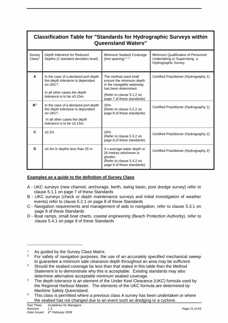
Classification Table for "Standards for Hydrographic Surveys within Queensland Waters"
Survey Class1
Depth tolerance for Reduced Depths (2 standard deviation level)
Minimum Seabed Coverage (line spacing) 2, 3
Minimum Qualification of Personnel Undertaking or Supervising a Hydrographic Survey
A In the case of a declared port depth the depth tolerance is dependant on UKC4. In all other cases the depth tolerance is to be ±0.15m.
The method used shall ensure the minimum depth in the navigable waterway has been determined.
(Refer to clause 5.1.2 on page 7 of these standards)
Certified Practitioner (Hydrography 1)
B5 In the case of a declared port depth the depth tolerance is dependant on UKC4.
In all other cases the depth tolerance is to be ±0.15m.
20% (Refer to clause 5.2.2 on page 8 of these standards)
Certified Practitioner (Hydrography 1)
C ±0.2m 20% (Refer to clause 5.3.2 on page 8,of these standards)
Certified Practitioner (Hydrography 2)
D ±0.3m in depths less than 25 m 3 x average water depth or 25 metres whichever is greater. (Refer to clause 5.4.2 on page 9 of these standards)
Certified Practitioner (Hydrography 2)
Examples as a guide to the definition of Survey Class
A - UKC surveys (new channel, anchorage, berth, swing basin, post dredge survey) refer to
clause 5.1.1 on page 7 of these Standards B - UKC surveys (check or depth maintenance surveys and initial investigation of weather
events) refer to clause 5.2.1 on page 8 of these Standards C - Navigation requirements and management of aids to navigation, refer to clause 5.3.1 on
page 8 of these Standards D - Boat ramps, small boat charts, coastal engineering (Beach Protection Authority), refer to
clause 5.4.1 on page 9 of these Standards
1 As guided by the Survey Class Matrix. 2 For safety of navigation purposes, the use of an accurately specified mechanical sweep
to guarantee a minimum safe clearance depth throughout an area may be sufficient. 3 Should the seabed coverage be less than that stated in this table then the Method
Statement is to demonstrate why this is acceptable. Existing standards may also determine alternative acceptable minimum seabed coverage.
4 The depth tolerance is an element of the Under Keel Clearance (UKC) formula used by the Regional Harbour Master. The elements of the UKC formula are determined by Maritime Safety Queensland.
5 This class is permitted where a previous class A survey has been undertaken or where the seabed has not changed due to an event such as dredging or a cyclone.
Part Three Guidelines for Managers Revision 1.3 Page 21 of 63 Date Issued 6th February 2009
3 DETERMINING A CLASS OF HYDROGRAPHIC SURVEY
This section introduces the risk criteria needed to undertake a consistent risk assessment within Queensland Waters for incidents resulting from an obstruction to navigation being missed by the hydrographic survey and provides advice about how to undertake such a risk assessment. To identify the class of survey required, a risk assessment is undertaken using a Consequence Matrix (Page 23), Likelihood Matrix (page 24) and the Survey Class Matrix (page 25). To determine the class of a hydrographic survey for a particular purpose, the Consequence and Likelihood Matrices are used to determine a number score which, when applied to the Survey Class Matrix Key, identifies the required class of hydrographic survey.
3.1 Consequence Matrix
Five risk criteria are used in the Consequence Matrix. These are:
• Risks to People • Risks to Property • Risks to the Environment • Risks to the Economy • Risks to External Relations
Each risk is outlined in greater detail in the Consequence Matrix (page 23). Each risk criterion should be assessed individually to assess the measure of impact associated with different types of loss. The highest consequence for any individual risk criteria should be used as the overall consequence value.
3.2 Likelihood Matrix
The use of a Likelihood Matrix is a practical translation of the probability of an incident occurring as a result of an obstruction to navigation being missed by the hydrographic survey.
3.3 Survey Class Matrix
The Survey Class Matrix combines the highest selected consequence and the likelihood of that particular incident occurring to determine a number score which is then applied to the Key to determine the survey class. The Survey Class Matrix Key has an overlap in the number score between the different classes of survey to allow some degree of flexibility on a case by case basis.
Part Three Guidelines for Managers Revision 1.3 Page 22 of 63 Date Issued 6th February 2009
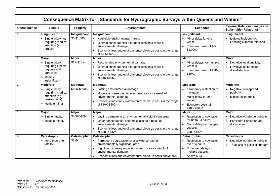
Consequence Matrix for "Standards for Hydrographic Surveys within Queensland Waters" Consequence People Property Environmental Economic External Relations (Image and
Stakeholder Relations) 0
Insignificant • Single injury not
requiring medical attention (eg bruise)
Insignificant $0-$1,000
Insignificant • Negligible environmental impact. • Minimal consequential economic loss as a result of
environmental damage. • Economic loss and environmental clean up costs in the range
of $0-$1,000.
Insignificant • Minor delay for one
vessel. • Economic costs of $0-
$1,000.
Insignificant • Isolated incident not
effecting external relations.
1 Minor • Single injury
requiring first aid (eg cuts and abrasions).
• Multiple insignificant
Minor $1K-$10K
Minor • Recoverable environmental damage. • Minimal consequential economic loss as a result of
environmental damage. • Economic loss and environmental clean up costs in the range
of $1K-$10K.
Minor • Minor delays for multiple
vessels. • Economic costs of $1K-
$10K.
Minor • Negative local publicity. • Low level stakeholder
dissatisfaction.
2
Moderate • Single injury
requiring medical attention (eg broken bone).
• Multiple minor
Moderate $10K-$500K
Moderate • Lasting environmental damage. • Moderate consequential economic loss as a result of
environmental damage. • Economic loss and environmental clean up costs in the range
of $10K-$500K.
Moderate • Temporary restriction to
navigation. • Major delay for one
vessel. • Economic costs of
$10K-$500K.
Moderate • Negative widespread
publicity. • Ministerial interest.
3
Major • Single fatality. • Multiple minor.
Major $500K-$5M
Major • Lasting damage to an environmentally significant area. • Major consequential economic loss as a result of
environmental damage. • Economic loss and environmental clean up costs in the range
of $500K-$5M.
Major • Restriction to navigation
for up to 24 hours. • Major delays to multiple
vessels. • $500K-$5M.
Major • Negative worldwide publicity. • Persistent Parliamentary
discussions.
4
Catastrophic • More than one
fatality.
Catastrophic $5M<
Catastrophic • Permanent degradation over a wide spread or
environmentally significant area. • Significant consequential economic loss as a result of
environmental damage. • Economic loss and environmental clean up costs above $5M.
Catastrophic • Restriction to navigation
over 24 hours. • Prolonged delays to
multiple vessels. • Above $5M.
Catastrophic • Negative worldwide publicity. • Total loss of political support.
Part Three Guidelines for Managers Revision 1.3 Page 23 of 63 Date Issued 6th February 2009
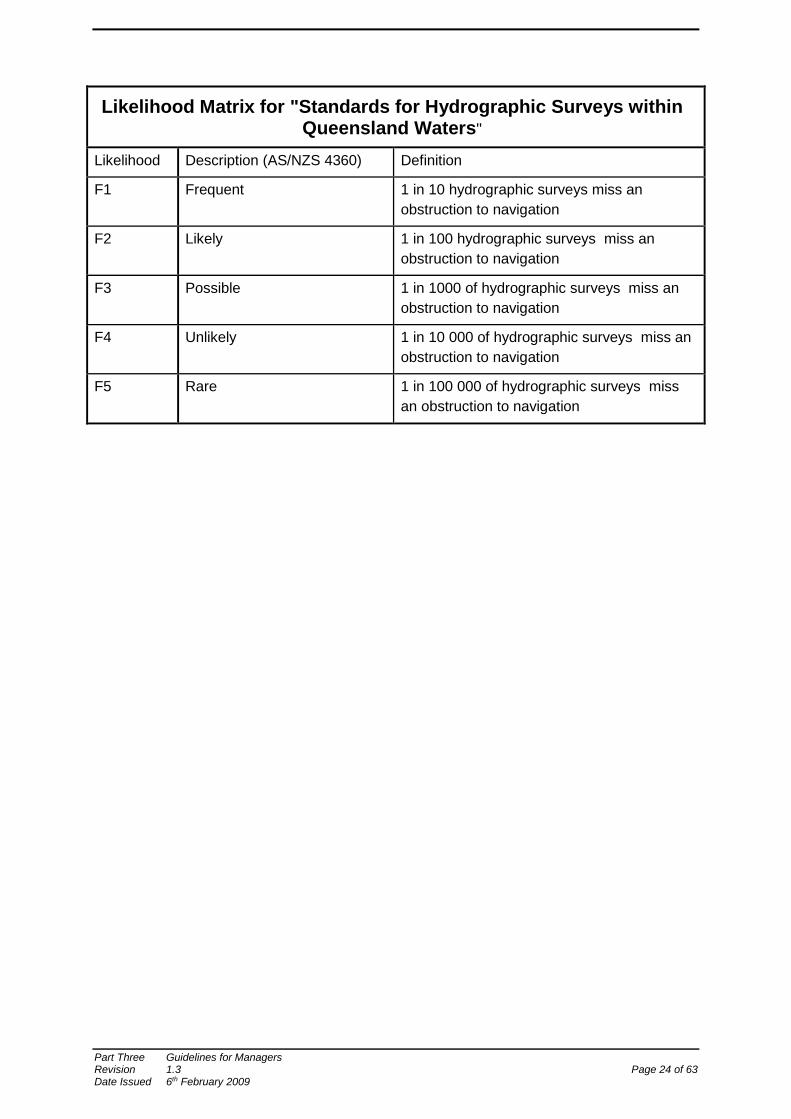
Likelihood Matrix for "Standards for Hydrographic Surveys within Queensland Waters"
Likelihood Description (AS/NZS 4360) Definition
F1 Frequent 1 in 10 hydrographic surveys miss an obstruction to navigation
F2 Likely 1 in 100 hydrographic surveys miss an obstruction to navigation
F3 Possible 1 in 1000 of hydrographic surveys miss an obstruction to navigation
F4 Unlikely 1 in 10 000 of hydrographic surveys miss an obstruction to navigation
F5 Rare 1 in 100 000 of hydrographic surveys miss an obstruction to navigation
Part Three Guidelines for Managers Revision 1.3 Page 24 of 63 Date Issued 6th February 2009
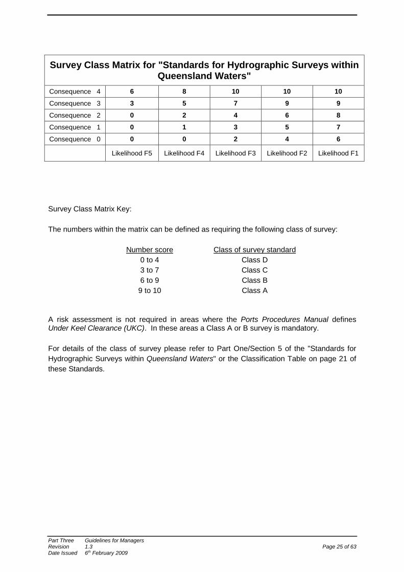
Survey Class Matrix Key: The numbers within the matrix can be defined as requiring the following class of survey:
Number score Class of survey standard 0 to 4 Class D 3 to 7 Class C 6 to 9 Class B 9 to 10 Class A
A risk assessment is not required in areas where the Ports Procedures Manual defines Under Keel Clearance (UKC). In these areas a Class A or B survey is mandatory. For details of the class of survey please refer to Part One/Section 5 of the "Standards for Hydrographic Surveys within Queensland Waters" or the Classification Table on page 21 of these Standards.
Survey Class Matrix for "Standards for Hydrographic Surveys within Queensland Waters"
Consequence 4 6 8 10 10 10
Consequence 3 3 5 7 9 9
Consequence 2 0 2 4 6 8
Consequence 1 0 1 3 5 7
Consequence 0 0 0 2 4 6
Likelihood F5 Likelihood F4 Likelihood F3 Likelihood F2 Likelihood F1
Part Three Guidelines for Managers Revision 1.3 Page 25 of 63 Date Issued 6th February 2009
4 MINIMUM QUALIFICATION OF PERSONNEL
The Classification Table provides a minimum level of certification required to undertake a hydrographic survey in Queensland Waters. This certification is provided through the Australasian Hydrographic Surveyors Certification Panel (AHSCP). Guidelines for certification can be downloaded from the following websites: www.isaust.org.au/groupHydrography/AHSAP/ http://www.spatialsciences.org.au/comm_LHS/ahsap.asp.
4.1 Phase in Period for Hydrographic Surveying Competencies
The Standard acknowledges that persons undertaking hydrographic surveys within Queensland Waters may not currently have the minimum qualifications of this Standard; however their skills and experience are sufficient for them to undertake hydrographic surveys in accordance with the Standard. Therefore until 1 January 2010, persons who are eligible for certification under Part Two/Section 2 of this Standard will be able to undertake or supervise a hydrographic survey. In the case of class A or B surveys, it is expected that the hydrographic surveyor would have been carrying out hydrographic surveys in any relevant port for five continuous years. This will allow time for such experienced persons to achieve the minimum qualifications of this Standard and become a certified hydrographic surveyor by 1 January 2010.
5 SURVEY INTERVAL
Most Queensland ports that operate on a minimum UKC have a dredged channel or approach area that can suffer from siltation and may result in a reduced draft for vessel movement. The need for regular surveys is a critical part of ensuring that the port remains a safe environment for shipping. The same rationale applies to recreational Small Craft Facilities, especially where they are marked by Aids to Navigation. Survey Interval documents have been developed to derive a consistent methodology to determine at what interval ports and recreational Small Craft Facilities are required to be surveyed. The survey interval methodology and score will be determined by Maritime Safety Queensland in consultation with the relevant stakeholders. The Survey Interval document consists of the Survey Interval Criteria (page 30) and a Survey Interval Schedule (page 33).
5.1 Survey Interval Criteria
The survey interval criteria document lists the fourteen criteria that are relevant to hydrographic survey and the weighting that has been placed on each of the criteria. The survey interval schedule document is used to determine the score for each survey area and then the interval at which this survey area should be surveyed.
Part Three Guidelines for Managers Revision 1.3 Page 26 of 63 Date Issued 6th February 2009
To determine a "score" for a particular survey area, the survey interval criteria (1 to 14) are assessed for a particular survey area and the scores entered in the corresponding criteria number (1 to 14) in the Criteria/Score column of the Survey Interval Schedule. Criteria 3 (Historical Rate of Siltation) is considered to be a critical factor in determining the survey interval. A high rate of siltation will require more frequent survey. For this reason, criteria 3 is the only criteria where a multiplier, other than one, is applied to the weight. For all other criteria, the weight is multiplied by one. The weighting of each selection criteria has been determined by a combined historical and risk analysis of areas where the interval of surveys has been consistent and has provided sufficient information for navigational safety. The weight was based on a scale of 0 to 20. A high risk factor means a high weight.
5.1.1 Criteria 1 Maintain Critical Depth
Criteria 1 applies to any channels, wharves, harbours and basins (shipping or small craft), where a nominated depth is required for navigation and dredging would be required to regain that depth if the area shoals. It is particularly important to limit the commercial impacts of any reduced draft for shipping movements.
Any area that requires the depth to be maintained scores 20, in criteria 1, on the Survey
Interval Schedule.
5.1.2 Criteria 2 DUKC Systems
This criteria is applicable to shipping channels where the Dynamic Under Keel
Clearance (DUKC) system is used. Any area that uses DUKC will score 20, in criteria 2, on the Survey Interval Schedule. If DUKC is applied then criteria 4 does not apply to the same area.
5.1.3 Criteria 3 Historical Rate of Siltation
The historical rate of siltation, on a yearly basis, can be determined by electronic comparison of digital terrain models or by perusal of plans. Regular surveys over five years should be the minimum requirement to determine a siltation rate. To determine a score for this criteria, multiply the weight by the siltation rate using the siltation rate as a whole number (ie 0.1 becomes 1, 0.2 becomes 2 etc). An example of this is Weipa where the average yearly siltation rate for the South Channel over the past 5 years has been calculated to be 0.2 metres. The score becomes 20 multiplied by 2 giving 40 which is entered in criteria 3, on the Survey Interval Schedule.
5.1.4 Criteria 4 SUKC Systems
This criteria applies to areas where the Static Under Keel Clearance (SUKC) system is used. Any area where a SUKC applies will score 20, in criteria 4, on the Survey Interval Schedule. If the area has already been scored under criteria 2, then criteria 4 does not apply.
5.1.5 Criteria 5 Lack of Knowledge of Siltation
If there is insufficient historical survey information or surveys were too infrequent to reliably determine a historical rate of siltation then Criteria 5 will apply. Any area that can not be scored under criteria 3 will score 20, in criteria 5, on the Survey Interval Schedule.
Part Three Guidelines for Managers Revision 1.3 Page 27 of 63 Date Issued 6th February 2009
5.1.6 Criteria 6 Seabed Material Type
This criteria differentiates between a rock or a soft (sand/mud) seabed. Any shoaling which can cause a vessel to ground in a rock area will have worse consequences than in a soft area. Any survey area that has a rock seabed will score 6, in criteria 6, on the Survey Interval Schedule.
5.1.7 Criteria 7 Berth Pocket Siltation
This criteria applies to berth areas where there is potential or known shoaling from material slumping from under the wharf or spillage of bulk product that will cause siltation. Spillage of product includes material that is swept or hosed from the wharf or from a ship while still at the wharf. Any berth area where this applies will score 15, in criteria 7, on the Survey Interval Schedule.
5.1.8 Criteria 8 Higher Risk of Vessel Impacting the Seabed
This criteria applies to narrow channels and berth pockets. Narrow channels that restrict sea room of a vessel can cause squat and bank effects to affect the manoeuvrability which may hamper steering and restrict passing ability. A berth area requires vessels, in particular loaded ships, to sit at low tide. Shoaling in these areas creates a higher risk of grounding or an incident. This criteria would exclude small recreational vessels that are typically less than 12 metres in length and that have manoeuvrability through size and shallow draft to avoid incidents. Any survey area that falls into this category will score 15, in criteria 8, on the Survey Interval Schedule.
5.1.9 Criteria 9 Usage Frequency
This criteria refers to the amount of traffic that uses the survey area and is divided into three categories to cover high, medium and low usage. Survey areas will fall into the three categories, 9a which will score 12, 9b which will score 8 and 9c which will score 4, on the Survey Interval Schedule
5.1.10 Criteria 10 Insurance Depth or Lack Thereof
This criteria only applies to survey areas where there is a maintained or nominated depth as applies in criteria 1. The insurance depth, or over dredging, acts as a silt trap to ensure the maintained depth takes longer to be affected by siltation. Areas where there is a maintained depth and where over dredging took place for insurance depths will score 0 and areas where there are no insurance depths will score 10, in criteria 10, on the Survey Interval Schedule.
5.1.11 Criteria 11 Critical Areas of a Navigation Channel
This criteria refers to a navigation channel where there is a critical area either seaward or inshore from the dredged channel that is shoaling or is at a depth that is close to, or at, the maintained depth. These areas should be monitored to ensure the integrity of the maintained depth. Examples of this would be at Karumba where there is a shoaling area between the dredged entrance channel and the wharf. At Mourilyan shipping has to negotiate the banks in the approaches after departing the entrance channel that has a maintained depth. Any area that has a critical area outside of the dredged channel will score 20, in criteria 11, on the Survey Interval Schedule.
Part Three Guidelines for Managers Revision 1.3 Page 28 of 63 Date Issued 6th February 2009
5.1.12 Criteria 12 Economic/Environmental Impact of an Incident
This criteria refers to the impact that an incident would have on a port area. A grounding that blocks the channel of a busy port would have a high economic impact while a collision that causes an oil spill would have a high environmental impact. This criteria has been divided into three categories to cover high, medium and low impact of an incident. Survey areas will fall into the three categories, 12H which will score 12, 12M which will score 6 and 12L which scores 0, on the Survey Interval Schedule.
5.1.13 Criteria 13 New or Developed Commercial Channel
A new or developed channel will have to be closely monitored until the siltation patterns have been established. If a channel is new, dredged or naturally deep, or an existing channel has been deepened and/or widened then this area will score 20, in criteria 13, on the Survey Interval Schedule.
5.1.14 Criteria 14 Small Craft Channel marked by Aids to Navigation
This criteria ensures that a small craft channel that is marked by Aids to Navigation is regularly surveyed to ensure that the Aids to Navigation delineate the navigation channel. This is a safe guard against liability and public safety obligations. Any survey area that is used by small craft and is marked by Aids to Navigation (buoys, beacons, leads) will score 10, in criteria 14 on the Survey Interval Schedule.
Part Three Guidelines for Managers Revision 1.3 Page 29 of 63 Date Issued 6th February 2009

SURVEY INTERVAL CRITERIA
Order Criteria Weight Remarks
1 Maintain critical depths eg 10.8m and commercial impacts
20 Channels, basins and harbours with maintained depths have commercial impacts when the depth is lost. Requires the most frequent survey to maintain depth
2 Dynamic Under Keel Clearance (DUKC) systems
20 Channels with DUKC require more frequent survey because there is less allowance for siltation and less margin for error
3 Historical Rate of Siltation (to score, multiply siltation rate by weight with .1 becoming 1 etc) ie in Weipa siltation rate is 0.2 (2 x 20 = 40)
20 Channels that have historically shown minimal siltation will require less survey than areas with a high rate of siltation
4 Static Under Keel Clearance (SUKC) 20 Channels with UKC require frequent survey to ensure allowance for siltation is not exceeded
5 Lack of knowledge of siltation (Use where siltation unknown)
20 Will require frequent survey until a history of siltation has been established
6 Seabed Material Types - Soft bottom vs. rock
Rock Seabed
Soft Seabed
6
0 The harder the seabed the worse the vessel damage as a consequence of a grounding
7 Berth pocket siltation from slumping under wharf or spillage of product eg Mourilyan/Weipa
15 Berth pockets where slumping from under the wharf or spillage of bulk product causes siltation will require survey more often
8 Higher risk of vessel impacting sea bed eg Channel width and berth pocket excluding small recreational vessels
15 Narrow channels where squat and bank effects become a factor and berth pockets where loaded ships sit at low tide, are high risk areas and require survey more often. (small recreational vessels for example, < 12m length)
9 Usage frequency a - high usage
b - medium usage
c - low usage
12
8
4
Areas of high usage, especially by large ships transiting at maximum draft, will require more frequent survey
10 Insurance depth or lack thereof. (Only where criteria 1 applies)
No
Yes
10
0 Insurance depths in a channel should ensure the maintained depth takes longer to be affected by siltation requiring less survey. Mourilyan berth pocket is problematic because it has no insurance depth
11 Critical areas of a navigation channel eg Karumba
20 Critical areas inside the navigation channel but outside defined dredge limits could require more frequent survey than the channel area
12
Economic/ Environmental impact of a incident
High
Medium
Low
12
6
0
A grounding at Quintell Beach would not have the same ramifications as one at Weipa or Hay Point. The entrance to Skardon River could be regarded as "high" because fuel barges are navigating a restricted and shallow area.
13 New or developed commercial channel 20 A new or developed (deepened/widened) channel will require frequent survey to establish siltation patterns
14 Small craft channel marked by Aids to Navigation
10 A small craft channel marked by Aids to Navigation should be surveyed regularly to ensure the Aids to Navigation delineate the navigation channel. Obligations for public safety and liability.
Part Three Guidelines for Managers Revision 1.3 Page 30 of 63 Date Issued 6th February 2009
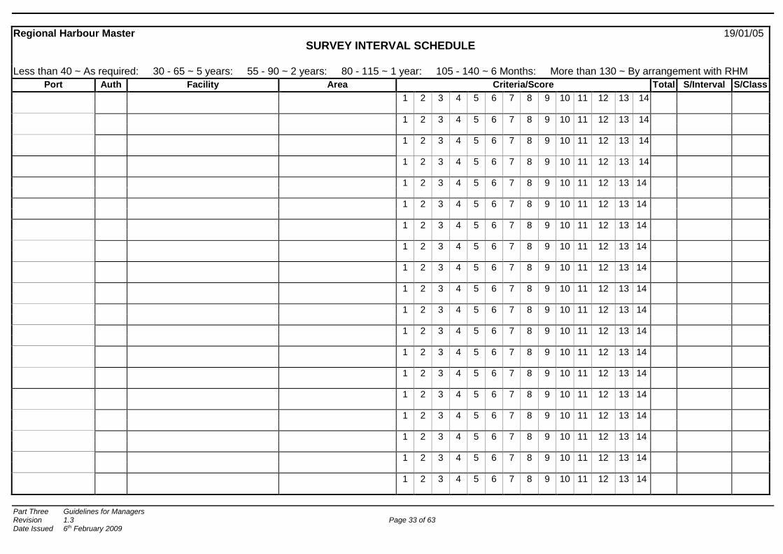
5.2 Survey Interval Schedule
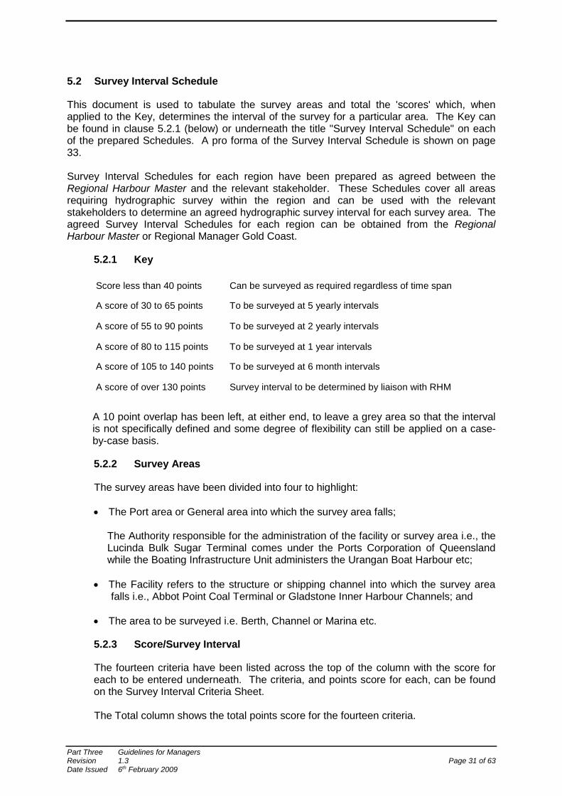
This document is used to tabulate the survey areas and total the 'scores' which, when applied to the Key, determines the interval of the survey for a particular area. The Key can be found in clause 5.2.1 (below) or underneath the title "Survey Interval Schedule" on each of the prepared Schedules. A pro forma of the Survey Interval Schedule is shown on page 33. Survey Interval Schedules for each region have been prepared as agreed between the Regional Harbour Master and the relevant stakeholder. These Schedules cover all areas requiring hydrographic survey within the region and can be used with the relevant stakeholders to determine an agreed hydrographic survey interval for each survey area. The agreed Survey Interval Schedules for each region can be obtained from the Regional Harbour Master or Regional Manager Gold Coast.
5.2.1 Key
Score less than 40 points Can be surveyed as required regardless of time span
A score of 30 to 65 points To be surveyed at 5 yearly intervals
A score of 55 to 90 points To be surveyed at 2 yearly intervals
A score of 80 to 115 points To be surveyed at 1 year intervals
A score of 105 to 140 points To be surveyed at 6 month intervals
A score of over 130 points Survey interval to be determined by liaison with RHM
A 10 point overlap has been left, at either end, to leave a grey area so that the interval is not specifically defined and some degree of flexibility can still be applied on a case-by-case basis.
5.2.2 Survey Areas
The survey areas have been divided into four to highlight: • The Port area or General area into which the survey area falls;
The Authority responsible for the administration of the facility or survey area i.e., the Lucinda Bulk Sugar Terminal comes under the Ports Corporation of Queensland while the Boating Infrastructure Unit administers the Urangan Boat Harbour etc;
• The Facility refers to the structure or shipping channel into which the survey area
falls i.e., Abbot Point Coal Terminal or Gladstone Inner Harbour Channels; and
• The area to be surveyed i.e. Berth, Channel or Marina etc.
5.2.3 Score/Survey Interval
The fourteen criteria have been listed across the top of the column with the score for each to be entered underneath. The criteria, and points score for each, can be found on the Survey Interval Criteria Sheet. The Total column shows the total points score for the fourteen criteria.
Part Three Guidelines for Managers Revision 1.3 Page 31 of 63 Date Issued 6th February 2009
The Survey Interval column contains the survey interval, for the survey area, determined by applying the points score in the total column to the points score key in the heading area. The survey interval would normally be determined by the Regional Harbour Master in consultation with other stakeholders.
5.2.4 Survey Class
This column contains the survey class. The Survey Class Matrix is used as a guide to determine the class of survey required. Details of the class of survey can be found on the Classification Table or in Part One/Section 5 of these Standards.
5.2.5 Updating the Survey Interval Schedule
The date as appears in the top right hand corner, of the heading area, is the date that the schedule is filled in or modified. This date should be updated every time changes are made to the document. The top left hand corner, of the heading area, shows the Region into which the survey areas fall (Both the date and region are contained in the header of the document).
6 FUTURE AUDIT OF STANDARDS
It is recommended that an audit be carried out, as appropriate, by an independent third party to ensure that the "Standards for Hydrographic Surveys within Queensland Waters" are adhered to and maintained by hydrographic surveyors carrying out hydrographic surveys in Queensland. The audit could be in the form of independent field checks, monitoring of field work as the hydrographic surveys are carried out and/or a desk top check of completed hydrographic surveys. The audit will ensure that the Standards are being met. The independent third party will be an AHSCP certified practitioner (Hydrography 1). The audit function will take the form of random checks plus targeted audit/s where an issue has been identified and requires checking. In addition, the Standards and Guidelines themselves will be reviewed every two years to ensure they reflect changing trends in technology, methods and equipment.
Part Three Guidelines for Managers Revision 1.3 Page 32 of 63 Date Issued 6th February 2009
Regional Harbour Master 19/01/05 SURVEY INTERVAL SCHEDULE
Less than 40 ~ As required: 30 - 65 ~ 5 years: 55 - 90 ~ 2 years: 80 - 115 ~ 1 year: 105 - 140 ~ 6 Months: More than 130 ~ By arrangement with RHM Port Auth Facility Area Criteria/Score Total S/Interval S/Class
1 2 3 4 5 6 7 8 9 10 11 12 13 14
1 2 3 4 5 6 7 8 9 10 11 12 13 14
1 2 3 4 5 6 7 8 9 10 11 12 13 14
1 2 3 4 5 6 7 8 9 10 11 12 13 14
1 2 3 4 5 6 7 8 9 10 11 12 13 14
1 2 3 4 5 6 7 8 9 10 11 12 13 14
1 2 3 4 5 6 7 8 9 10 11 12 13 14
1 2 3 4 5 6 7 8 9 10 11 12 13 14
1 2 3 4 5 6 7 8 9 10 11 12 13 14
1 2 3 4 5 6 7 8 9 10 11 12 13 14
1 2 3 4 5 6 7 8 9 10 11 12 13 14
1 2 3 4 5 6 7 8 9 10 11 12 13 14
1 2 3 4 5 6 7 8 9 10 11 12 13 14
1 2 3 4 5 6 7 8 9 10 11 12 13 14
1 2 3 4 5 6 7 8 9 10 11 12 13 14
1 2 3 4 5 6 7 8 9 10 11 12 13 14
1 2 3 4 5 6 7 8 9 10 11 12 13 14
1 2 3 4 5 6 7 8 9 10 11 12 13 14
1 2 3 4 5 6 7 8 9 10 11 12 13 14
Part Three Guidelines for Managers Revision 1.3 Page 33 of 63 Date Issued 6th February 2009
PART FOUR GUIDELINES FOR HYDROGRAPHIC SURVEYORS
Part Four Guidelines for Hydrographic Surveyors Revision 1.3 Page 34 of 63 Date Issued 6th February 2009
1 INTRODUCTION
The Guidelines for Hydrographic Surveyors and the Guidelines for Managers are the two principal references of the "Standards for Hydrographic Surveys within Queensland Waters". The Guidelines for Hydrographic Surveyors:
• Provides 'best practice' advice for hydrographic surveyors to achieve a particular class of
survey; and
• Provides 'best practice' advice for planning a project and developing a Method Statement. The user of Part Four should have a strong working knowledge of hydrographic surveying or have access to professional advice on this matter.
2 PROJECT INSTRUCTION
It is vital to a successful project that clear written instructions are received and understood prior to any work being undertaken. The Project Instruction will assist the hydrographic surveyor in generating the Method Statement and ensure the correct area is surveyed to the required class. At a minimum the Project Instruction should contain information on the;
Purpose of the survey
Estimated commencement and completion times
Survey requirements for each area including declared depths and key depths
References to previous surveys in that area
Positioning control and datum's to be used
Output formats and timeline for delivery
3 HORIZONTAL DATUM
The horizontal datum should be tied into the Queensland 100km network directly via a 1st order mark. If a third party differential service is used it should be ensured that their control is tied into the Australian National Network (ANN).
3.1 Control Points
Control points are those marks established for base stations, reference stations, Tide Gauge Bench Marks (TGBM) or any other mark used as a base from which control for the survey is extended. Control points should be established and documented according to the Standards and Recommended Practices for Control Surveys as published by the Intergovernmental Committee on Surveying and Mapping (ICSM). Further information can be downloaded from the following website:
http://www.icsm.gov.au/icsm/publications/sp1/ Form 6 sketch plans should be forwaded to Department of Natural Resources Mines and Energy.
Part Four Guidelines for Hydrographic Surveyors Revision 1.3 Page 35 of 63 Date Issued 6th February 2009

4 VERTICAL DATUM
The elevation of the TGBM should be confirmed by independent and redundant measurements to at least three benchmarks (recovery marks). This should be carried out upon installation of a tide gauge and annually thereafter. In the case of marks on structures (particularly offshore structures), at least two of these marks will be on independent structures. Tide gauges should be setup at each location as identified in the Co-tidal Information as supplied by Maritime Safety Queensland.
4.1 Real Time Kinematic (RTK) GPS
The use of RTK should follow the above mentioned procedures with physical checks made at each tide gauge location. As the range of tides varies from place to place chart datum is not necessarily planar, horizontal, nor parallel to the geoid, ellipsoid, mean sea level or Australian Height Datum.
4.2 Clearance Heights
Clearance heights under bridges, wires, power cables or other such hazards are to be determined as height above/below Highest Astronomical Tide (HAT).
4.3 Sources of additional information
The Permanent Committee on Tides and Mean Sea Level (PCTMSL) “Recommended Operating Procedures for Tide Gauges on the National Network” and “Tide Gauge Survey Instructions”.
5 EQUIPMENT CALIBRATION/CERTIFICATION
Equipment that cannot be field calibrated should be maintained and calibrated to manufacturers' specifications. All manufacturers' calibration and test certificates should be retained for the life of the equipment. Calibrations should be carried out upon major repair of a unit. Transducer beamwidth tests should be obtained from the manufacturer clearly showing the 3db detection angle. Where these are not available, field beamwidth tests should be carried out and fully documented.
6 HORIZONTAL POSITIONING
Horizontal position should be collected utilising GPS (either DGPS, RTK).
6.1 Horizontal Tolerance
Horizontal tolerance should be determined from collecting data over a 1st order mark. Minimum data to be collected over a half hour period, however a 24 hour period is preferable, especially on more permanent base station setups to ensure a more statistically valid result that encapsulates a majority of satellite geometry.
Part Four Guidelines for Hydrographic Surveyors Revision 1.3 Page 36 of 63 Date Issued 6th February 2009
6.2 Position Checks
Position checks for gross errors should be carried out on a daily basis. These should consist of both static and dynamic checks. Static checks can include laying alongside a fixed structure of known position, permanent berthing location of survey vessel etc. Dynamic checks include running along and across a line of leads and double pass on beacons.
6.3 Rejection Criteria
The minimum rejection criteria for DGPS:
• DGPS correction age should not exceed 15 seconds.
• PDOP is not to exceed 6.
• Minimum number of healthy satellites being tracked is 4.
• Minimum elevation for satellites is 10o from the horizontal.
The minimum rejection criteria for RTKGPS:
• PDOP is not to exceed 6.
• Minimum number of healthy satellites being tracked is 5.
• Minimum elevation for satellites is 15o from the horizontal.
7 TIDE GAUGES
7.1 Automatic Tide Gauges
Automatic tide gauges recording at intervals not greater than 10 minutes should be utilised. The averaging should be based on a 2 minute period recorded with a 1 minute lag. Prior to installation tide gauges should be calibrated for time, offset and scale. Once installed similar checks should be carried out to ensure that the tide gauge is set to datum.
7.2 Tide Boards
The tide board should be set to datum using any standard surveying technique that is one order of magnitude better than the required output of the tidal recording system. The accuracy of the tide board markings should be confirmed, particularly if the board is installed as a number of sections. Where the tide board is installed at exposed locations, a stilling well should be fitted to the face of the board to enable accurate water level checks in all weather conditions.
Part Four Guidelines for Hydrographic Surveyors Revision 1.3 Page 37 of 63 Date Issued 6th February 2009
7.3 Water Level Checks
It is prudent practice to check the recordings of both height and time (the so called water level check) at the beginning and end of any survey for which tidal recordings are required. This also applies to RTK operations. Initial establishment should include checks at high, low and mid waters to verify scale, latency and any environmental conditions of the tide gauge. Tidal recorders may be checked using tide boards or other tidal height checking mechanisms “dip tapes”, portable stilling wells, and the like. Such equipment and the reference marks used with it must be set and confirmed in the same manner as for the tide board. For additional information, refer to the PCTMSL “Tide Gauge Survey Instructions”
8 DEPTH MEASUREMENT
Soundings should be gathered using acoustic techniques.
8.1 Vessel Squat
Squat for the survey vessel should be determined over the full range of operating speeds. Speed should be related to engine RPMs. RPM intervals should be selected to adequately define the squat curve. Where a vessel has trim controls these should be optimised for the expected sounding speed and then noted and held fixed for the whole squat test. Surveys should be typically run at the bottom of the squat curve to minimise error due to incorrect setting of the engine RPMs. Squat values should be redetermined following any major refit (eg. engine changes, new fuel tanks, trim tabs etc.)
8.2 Transducer Motion (Heave)
Transducer motion or heave can be compensated for by a variety of methods which typically include a Motion Reference Unit (MRU), RTK or manual heave reduction. MRUs should be used within the manufacturers stated limitations. Daily check lines run into and with the swell over a smooth seabed should be carried out to ensure correct settings and operation. Where RTK is used the motion should be sufficiently slow enough to be able to differentiate between heave and high frequency noise. Manual heave reduction should be limited to values less than twice the allowable depth tolerance of the class of survey (eg depth tolerance 0.15, transducer motion should be less than 0.30m). Care should also be taken as to direction of lines in relation to the wave direction. In areas of sand ridging the careful selection of conditions and line direction should be considered. In all cases the method of heave correction should be confirmed over a flat sea floor.
8.3 Single Beam Echo Sounder (SBES)
Echo sounders are always to be set to read depth below the surface of the water, and never to depth below the keel. Before use, the sounder must be calibrated precisely and adjusted for draft setting, index error and sound velocity (SV).
Part Four Guidelines for Hydrographic Surveyors Revision 1.3 Page 38 of 63 Date Issued 6th February 2009
Index error and draught setting should be determined from a shallow bar check. The SV is determined by a deep bar check. The depth should be selected based on the key depth of the survey. Where an SV probe is used it should be verified on a weekly basis against the values obtained from the echo sounder during a deep bar check. When bar checking it should be ensured that the motion sensor (where applicable) is turned off. Following setting of the SV, operation of the sounder should be checked against the bar at regular intervals up to the original depth that the draft was determined from. By whatever method an echo sounder is calibrated, it should not be done until the equipment is thoroughly warmed up. Where an echo sounder has multiple frequencies, each frequency is to be calibrated independently in order to allow for the different response times of the transducers. The marks on the bar lowering lines should allow for the appropriate mark to be placed on the sea surface when bar-checking, and not at the deck-edge. The lengths and markings of bar-check lines must be verified at regular intervals, typically monthly.
8.4 Multi-Beam Echo Sounder (MBES)
Initial calibration of a MBES should be carried out with assistance from the manufacturer. When the MBES is permanently installed check calibrations should be run at monthly intervals. When the MBES is installed with removable or stowable mounts, check calibrations should be carried out on a daily basis. All calibration parameters should be carefully documented and compared against check calibrations to ensure all sensors and offsets are within the manufacturer's tolerance. Sound velocity checks should be based on site specific conditions (ie river vs open water) and be undertaken on at least a daily basis before and after a survey. Typically, variations > 2ms indicate that more frequent checks should be made. The system should be recalibrated anytime key sensors are repaired or replaced.
8.5 Physical (Leadline/Sounding Pole)
A leading line (or sounding pole) can be used to determine soundings along the face of a wharf (or jetty) provided the lead line has been properly soaked, stretched and calibrated prior to use. Environmental conditions should be conducive to accurate soundings that i.e. calm water surface, lack of current etc.
9 SEABED COVERAGE
In order to determine the required line spacing for a hydrographic survey to meet the Standard, the line spacing needs to be primarily designed around the expected seabed coverage of the echo sounder. Other factors to be taken into consideration include the material type, survey history and the purpose of the survey In the instance of progressive hydrographic surveys during a dredging campaign, interlining of each survey can be taken into account to define the minimum depth (eg 5 metre line spacing for one survey can be offset by 2.5 metres for the next survey). Where the seabed is soft material such as silty mud the minimum depth could be achieved using a method as detailed in 8.3.1 below.
Part Four Guidelines for Hydrographic Surveyors Revision 1.3 Page 39 of 63 Date Issued 6th February 2009
Where the seabed is hard material such as rock it would be recommended that the area be theoretically fully ensonified especially when the purpose of the hydrographic survey is to provide a declared depth and/or clearance for development dredging. Seabed coverage for across the track and along the track can be calculated from the formulas in 8.1 and 8.2 where:
depthkeyKDBeamwidthBW
CoverageC
==
=
9.1 Across Track
The seabed coverage should be determined from the beam width of the acoustic system at the 3db detection level. In the case of Multi-Beam Systems, the beamwidth will be the angle at which the soundings will no longer meet the required depth tolerance. Roll limits should also be calculated at this time to define motion limits of the vessel. Single beam roll limits are typically half the beamwidth.
9.1.1 Class A
( )( )KDBWC ×××= 5.0tan2
From this formula the line spacing can be determined. Across track line running errors should typically be less than half the coverage.
9.1.2 Class B, C and D
WaterwayNavigableofWidthC ×= 2.0
( )( )KDBWCLinesofNumber
×××=
5.0tan2
9.2 Along Track
The seabed coverage should be calculated based on the fore aft beamwidth, ping repetition rate and speed of vessel. Pitch limits should also be calculated at this time to define motion limits of the vessel. Single beam pitch limits are typically half the beamwidth.
( )( )KDBWC ×××= 5.0tan2 ( )smraterepetitionPingCondperCoverage /sec ×=
( ) 18523600sec ×= ondperCoverageknotsspeedvesselMaximum
9.3 Sweep System
A mechanical sweep system could be employed as an alternative to relying on acoustic systems for seabed coverage. This will vary depending on material type and previous survey history of the area. Sweep systems should not be used when development dredging of hard material has occurred. In all cases an acoustic system in conjunction with these techniques should still be used.
Part Four Guidelines for Hydrographic Surveyors Revision 1.3 Page 40 of 63 Date Issued 6th February 2009
9.3.1 Bed Leveller
Where maintenance dredging is being carried out and the area has been previously cleared to depth, the use of a bed leveller as a means of ensuring the minimum depth could be employed. If this system is utilised, the bed leveller should be capable of automatically recording its tracks to ensure that the bar has truly swept the entire bottom. If resistance is met on the bar it should be raised in 0.1m intervals and area swept until such times as no resistance is met. The bar should be calibrated and observed tides applied to ensure that the bar depth is set within the required depth tolerance. Close spaced (typically 5m) acoustic lines should still be run to verify the minimum depth.
9.4 Line Spacing and Design
Where full coverage is not required, careful design of the survey lines should be used. More lines should be concentrated in areas of expected shoaling. For example the Port of Weipa has a 105m wide channel. Lines would be concentrated near the toelines which is historically the area of highest siltation. Wider spacing would be used towards the centre of the channel where traditionally the channel has always been at or below the declared depth. Toe lines should be run parallel at a half beamwidth inside the navigable waterway. Berth pockets should be run longitudinally within the sounding boundary run at half beamwidth off. Ends of the berth pocket can be run parallel and half beamwidth off however it is usually not necessary. Cross lines can be utilised to cover an area however they are not the most efficient use of vessel time.
10 SOUNDING REDUCTION
10.1 Vertical
A scheme dividing the ship channels and coastal waters into a number of segments “co-tidal zones” has been established by Maritime Safety Queensland. Each “co-tidal zone” details the tidal stations to be used and the assumptions to be used when reducing soundings. Typically the “co-tidal zone” information (in this case, East Channel, Moreton Bay) has the form:
• Linearly interpolate the tidal readings between the Brisbane Bar tidal station 046046A Latitude 27° 22’ S Longitude 153° 10’ E & the East Channel Beacon, station 046208B Latitude 27° 14’ S Longitude 153° 20’ E
Datum is LAT
There are two commonly accepted interpolation techniques. They are: Linear and Planar.
10.1.1 Linear Technique
The tidal height at a point along the line joining the tidal stations is interpolated by distance from simultaneous readings from each station. All points on a line at right angles to this point are assumed to have the same tidal height.
Part Four Guidelines for Hydrographic Surveyors Revision 1.3 Page 41 of 63 Date Issued 6th February 2009
10.1.2 Planar Technique
The planar interpolation technique assumes that the water surface is a geometric plane between three tidal stations. In this way any cross slope can be incorporated into the interpolation.
10.2 Tidal Predictions
For class C and D surveys estimates of the tidal times and heights may be suitable. Physical checks should be carried out to determine the suitability of these methods. The following processes are usually employed to make these estimates:
• Enhanced harmonic tidal prediction (Tidal observations and predictions for some nearby place are necessary if this process is used).
• Rise ratio, constant and time difference (This process should be based on observed tidal times and heights from some nearby place.)
In both cases physical checks before and after each survey session should be carried as a minimum to assure that this method is complying with the required depth tolerance.
10.3 Sounding Reduction by AUSHYDROID
The height of the sounding platform may be measured directly as an ellipsoidal height using the Global Positioning System (GPS). As already noted, chart datum is not necessarily planar (flat) or a surface parallel to the ellipsoid through the RTK reference height control mark. Accordingly it is necessary to apply the AUSHYDROID in order to obtain the soundings relative to chart datum. At the present time the AUSHYDROID can only be obtained at the tidal stations where the LAT and ellipsoidal heights are both known. As in the case of tidal reductions it is necessary to make the same assumptions in order to interpolate the AUSHYDROID at places in between. The AUSHYDROID values are noted in the “co-tidal zone” details where known. Advice should be sought from Maritime Safety Queensland tides section if discrepancies are discovered or suspected from using RTK.
11 PRELIMINARY DATA PRESENTATION
The Hydrographic surveyor is required to provide feedback to the Regional Harbour Master prior to departing site. This is essential for any Class A or Class B surveys or any surveys with high risk and high consequences. If in doubt the Hydrographic surveyor should make contact with the Regional Harbour Master to discuss the survey and results obtained. Ideally a field plot provides the best representation of the information. Field plots do not need to contain all title information or colouring as they are draft plots only, used to highlight the area surveyed and soundings obtained.
12 DATA PRESENTATION
Data should be presented on a shoal biased basis at spacing suitable to the final scale of the plan. The position of the sounding should not be moved and the location should be at the decimal place of the displayed sounding.
Part Four Guidelines for Hydrographic Surveyors Revision 1.3 Page 42 of 63 Date Issued 6th February 2009

12.1 Key Depths
Soundings shallower than the key depth should be coloured red for easy location and identification.
12.2 Compiled Data
Where a compiled plan is produced it should clearly delineate each area of survey and its date. For a short term dredging campaign the above need not be carried out. The latest survey need only be clearly delineated and the date of survey on the plan should reflect this latest information.
12.3 Contours
Contours can be generated by a variety of methods and data sets. The method of contour generation needs to be carefully selected, based on the intended use of the survey. Where the survey is to be used for navigation and/or generalised design, the shoal biased soundings should be used to produce the contours. This provides a smoother, more readable contour. In cases such as dredging, information as to what has been achieved on the seabed is required; all data should be used to generate the contours. This will highlight trenches, features and so on, that would not be obvious from the minimum depths displayed on the plan. Standard contours to be shown are -1, 0, 1, 2, 3, 5, 10, 20 and key depth (Red). Contours should be generated as inclusive i.e. the vessel hits the contour before it hits the seabed.
13 DATA QUALITY
A statistical analysis of the survey data should be carried out. To validate the repeatability of the data, survey lines should be run in historically stable ground and compared with historical data. Internal tolerance of the survey should be assessed from analysing cross lines.
14 DATA RETENTION
All raw and processed data should be retained until a new survey has been carried out over the entire area of the previous survey. Plans and x,y,z data should be maintained for a minimum of ten years. The x,y,z file should be referenced to the plan to ensure all relevant metadata is available.
15 SURVEY PLAN
15.1 Scale
For class A & B surveys scale should conform to the following: Berths 1:1000 Channels 1:2000
Other scales may be used for presentation but the base plan should be at this scale. For class C & D surveys scale should be based on: Part Four Guidelines for Hydrographic Surveyors Revision 1.3 Page 43 of 63 Date Issued 6th February 2009
The nominal spacing of single beam survey lines that is best displayed on one of the following standard scales: 1:500, 1:1000, 1:2000, 1:5000 and 1:10000. Other scales may be used for presentation but the base plan should be at one of these scales.
Part Four Guidelines for Hydrographic Surveyors Revision 1.3 Page 44 of 63 Date Issued 6th February 2009
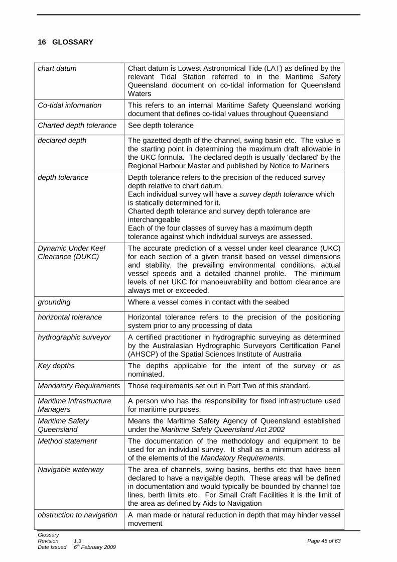
16 GLOSSARY
chart datum Chart datum is Lowest Astronomical Tide (LAT) as defined by the
relevant Tidal Station referred to in the Maritime Safety Queensland document on co-tidal information for Queensland Waters
Co-tidal information This refers to an internal Maritime Safety Queensland working document that defines co-tidal values throughout Queensland
Charted depth tolerance See depth tolerance
declared depth The gazetted depth of the channel, swing basin etc. The value is the starting point in determining the maximum draft allowable in the UKC formula. The declared depth is usually 'declared' by the Regional Harbour Master and published by Notice to Mariners
depth tolerance Depth tolerance refers to the precision of the reduced survey depth relative to chart datum. Each individual survey will have a survey depth tolerance which is statically determined for it. Charted depth tolerance and survey depth tolerance are interchangeable Each of the four classes of survey has a maximum depth tolerance against which individual surveys are assessed.
Dynamic Under Keel Clearance (DUKC)
The accurate prediction of a vessel under keel clearance (UKC) for each section of a given transit based on vessel dimensions and stability, the prevailing environmental conditions, actual vessel speeds and a detailed channel profile. The minimum levels of net UKC for manoeuvrability and bottom clearance are always met or exceeded.
grounding Where a vessel comes in contact with the seabed
horizontal tolerance Horizontal tolerance refers to the precision of the positioning system prior to any processing of data
hydrographic surveyor A certified practitioner in hydrographic surveying as determined by the Australasian Hydrographic Surveyors Certification Panel (AHSCP) of the Spatial Sciences Institute of Australia
Key depths The depths applicable for the intent of the survey or as nominated.
Mandatory Requirements Those requirements set out in Part Two of this standard.
Maritime Infrastructure Managers
A person who has the responsibility for fixed infrastructure used for maritime purposes.
Maritime Safety Queensland
Means the Maritime Safety Agency of Queensland established under the Maritime Safety Queensland Act 2002
Method statement The documentation of the methodology and equipment to be used for an individual survey. It shall as a minimum address all of the elements of the Mandatory Requirements.
Navigable waterway The area of channels, swing basins, berths etc that have been declared to have a navigable depth. These areas will be defined in documentation and would typically be bounded by channel toe lines, berth limits etc. For Small Craft Facilities it is the limit of the area as defined by Aids to Navigation
obstruction to navigation A man made or natural reduction in depth that may hinder vessel movement
Glossary Revision 1.3 Page 45 of 63 Date Issued 6th February 2009
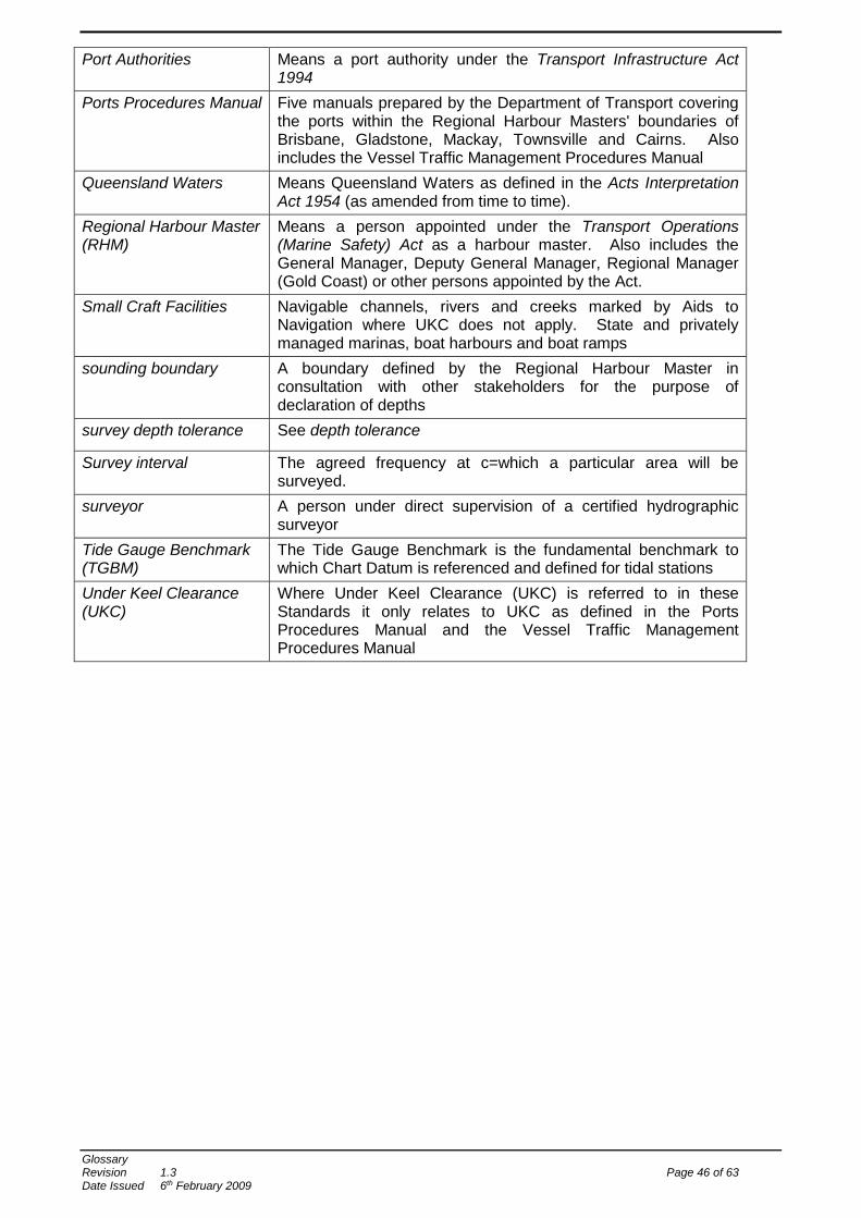
Port Authorities Means a port authority under the Transport Infrastructure Act 1994
Ports Procedures Manual Five manuals prepared by the Department of Transport covering the ports within the Regional Harbour Masters' boundaries of Brisbane, Gladstone, Mackay, Townsville and Cairns. Also includes the Vessel Traffic Management Procedures Manual
Queensland Waters Means Queensland Waters as defined in the Acts Interpretation Act 1954 (as amended from time to time).
Regional Harbour Master (RHM)
Means a person appointed under the Transport Operations (Marine Safety) Act as a harbour master. Also includes the General Manager, Deputy General Manager, Regional Manager (Gold Coast) or other persons appointed by the Act.
Small Craft Facilities Navigable channels, rivers and creeks marked by Aids to Navigation where UKC does not apply. State and privately managed marinas, boat harbours and boat ramps
sounding boundary A boundary defined by the Regional Harbour Master in consultation with other stakeholders for the purpose of declaration of depths
survey depth tolerance See depth tolerance
Survey interval The agreed frequency at c=which a particular area will be surveyed.
surveyor A person under direct supervision of a certified hydrographic surveyor
Tide Gauge Benchmark (TGBM)
The Tide Gauge Benchmark is the fundamental benchmark to which Chart Datum is referenced and defined for tidal stations
Under Keel Clearance (UKC)
Where Under Keel Clearance (UKC) is referred to in these Standards it only relates to UKC as defined in the Ports Procedures Manual and the Vessel Traffic Management Procedures Manual
Glossary Revision 1.3 Page 46 of 63 Date Issued 6th February 2009
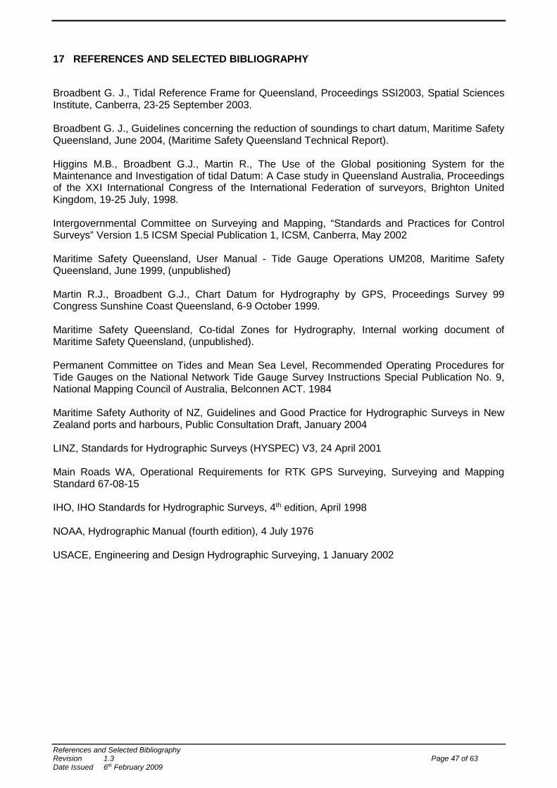
17 REFERENCES AND SELECTED BIBLIOGRAPHY
Broadbent G. J., Tidal Reference Frame for Queensland, Proceedings SSI2003, Spatial Sciences Institute, Canberra, 23-25 September 2003.
Broadbent G. J., Guidelines concerning the reduction of soundings to chart datum, Maritime Safety Queensland, June 2004, (Maritime Safety Queensland Technical Report).
Higgins M.B., Broadbent G.J., Martin R., The Use of the Global positioning System for the Maintenance and Investigation of tidal Datum: A Case study in Queensland Australia, Proceedings of the XXI International Congress of the International Federation of surveyors, Brighton United Kingdom, 19-25 July, 1998.
Intergovernmental Committee on Surveying and Mapping, “Standards and Practices for Control Surveys” Version 1.5 ICSM Special Publication 1, ICSM, Canberra, May 2002
Maritime Safety Queensland, User Manual - Tide Gauge Operations UM208, Maritime Safety Queensland, June 1999, (unpublished)
Martin R.J., Broadbent G.J., Chart Datum for Hydrography by GPS, Proceedings Survey 99 Congress Sunshine Coast Queensland, 6-9 October 1999.
Maritime Safety Queensland, Co-tidal Zones for Hydrography, Internal working document of Maritime Safety Queensland, (unpublished).
Permanent Committee on Tides and Mean Sea Level, Recommended Operating Procedures for Tide Gauges on the National Network Tide Gauge Survey Instructions Special Publication No. 9, National Mapping Council of Australia, Belconnen ACT. 1984 Maritime Safety Authority of NZ, Guidelines and Good Practice for Hydrographic Surveys in New Zealand ports and harbours, Public Consultation Draft, January 2004 LINZ, Standards for Hydrographic Surveys (HYSPEC) V3, 24 April 2001 Main Roads WA, Operational Requirements for RTK GPS Surveying, Surveying and Mapping Standard 67-08-15 IHO, IHO Standards for Hydrographic Surveys, 4th edition, April 1998 NOAA, Hydrographic Manual (fourth edition), 4 July 1976 USACE, Engineering and Design Hydrographic Surveying, 1 January 2002
References and Selected Bibliography Revision 1.3 Page 47 of 63 Date Issued 6th February 2009
APPENDIX 1 METHOD STATEMENT
Document 630/046/007
Appendix 1 Method Statement Revision 1.3 Page 48 of 63 Date Issued 6th February 2009
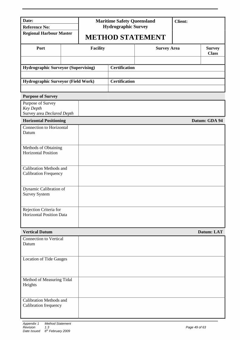
Date: Maritime Safety Queensland Hydrographic Survey
Client:
Reference No: Regional Harbour Master
METHOD STATEMENT Port Facility Survey Area Survey
Class
Hydrographic Surveyor (Supervising) Certification
Hydrographic Surveyor (Field Work) Certification
Purpose of Survey
Purpose of Survey Key Depth Survey area Declared Depth
Horizontal Positioning Datum: GDA 94 Connection to Horizontal Datum
Methods of Obtaining Horizontal Position
Calibration Methods and Calibration Frequency
Dynamic Calibration of Survey System
Rejection Criteria for Horizontal Position Data
Vertical Datum Datum: LAT Connection to Vertical Datum
Location of Tide Gauges
Method of Measuring Tidal Heights
Calibration Methods and Calibration frequency
Appendix 1 Method Statement Revision 1.3 Page 49 of 63 Date Issued 6th February 2009
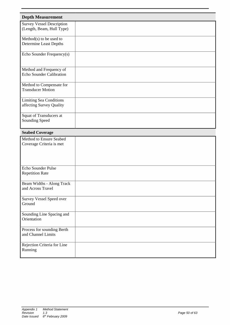
Depth Measurement
Survey Vessel Description (Length, Beam, Hull Type)
Method(s) to be used to Determine Least Depths
Echo Sounder Frequency(s)
Method and Frequency of Echo Sounder Calibration
Method to Compensate for Transducer Motion
Limiting Sea Conditions affecting Survey Quality
Squat of Transducers at Sounding Speed
Seabed Coverage Method to Ensure Seabed Coverage Criteria is met
Echo Sounder Pulse Repetition Rate
Beam Widths - Along Track and Across Travel
Survey Vessel Speed over Ground
Sounding Line Spacing and Orientation
Process for sounding Berth and Channel Limits
Rejection Criteria for Line Running
Appendix 1 Method Statement Revision 1.3 Page 50 of 63 Date Issued 6th February 2009
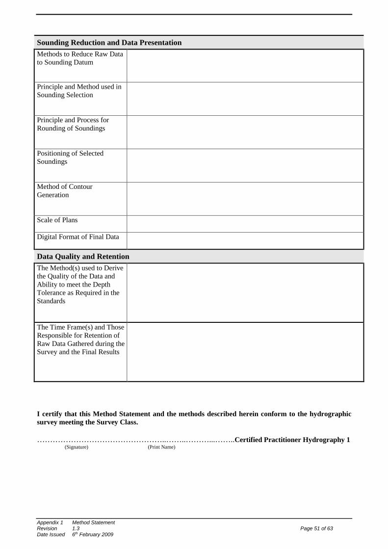
Sounding Reduction and Data Presentation Methods to Reduce Raw Data to Sounding Datum
Principle and Method used in Sounding Selection
Principle and Process for Rounding of Soundings
Positioning of Selected Soundings
Method of Contour Generation
Scale of Plans
Digital Format of Final Data
Data Quality and Retention The Method(s) used to Derive the Quality of the Data and Ability to meet the Depth Tolerance as Required in the Standards
The Time Frame(s) and Those Responsible for Retention of Raw Data Gathered during the Survey and the Final Results
I certify that this Method Statement and the methods described herein conform to the hydrographic survey meeting the Survey Class. …………………………………………..……..………...……..Certified Practitioner Hydrography 1
(Signature) (Print Name)
Appendix 1 Method Statement Revision 1.3 Page 51 of 63 Date Issued 6th February 2009
APPENDIX 2 METHOD STATEMENT EXAMPLE
Appendix 2 Method Statement Example Revision 1.3 Page 52 of 63 Date Issued 6th February 2009
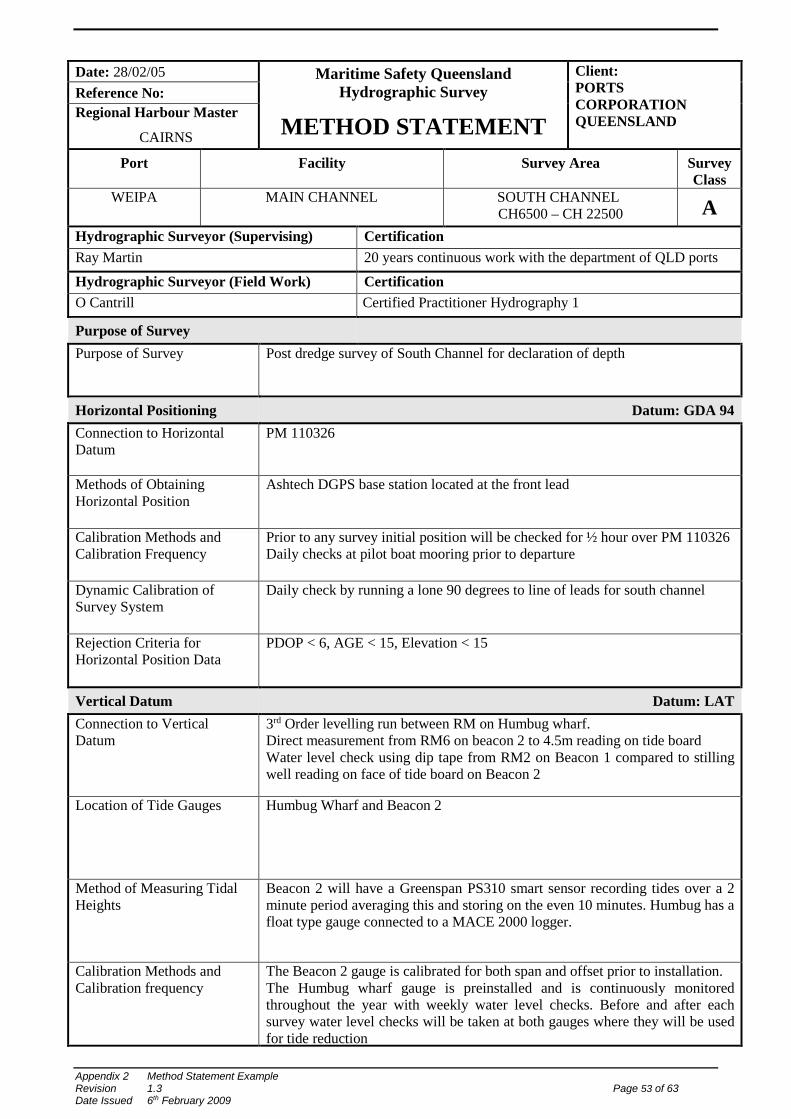
Date: 28/02/05 Maritime Safety Queensland
Hydrographic Survey Client: PORTS CORPORATION QUEENSLAND
Reference No: Regional Harbour Master
CAIRNS METHOD STATEMENT Port Facility Survey Area Survey
Class WEIPA MAIN CHANNEL SOUTH CHANNEL
CH6500 – CH 22500 A Hydrographic Surveyor (Supervising) Certification Ray Martin 20 years continuous work with the department of QLD ports
Hydrographic Surveyor (Field Work) Certification O Cantrill Certified Practitioner Hydrography 1
Purpose of Survey
Purpose of Survey
Post dredge survey of South Channel for declaration of depth
Horizontal Positioning Datum: GDA 94 Connection to Horizontal Datum
PM 110326
Methods of Obtaining Horizontal Position
Ashtech DGPS base station located at the front lead
Calibration Methods and Calibration Frequency
Prior to any survey initial position will be checked for ½ hour over PM 110326 Daily checks at pilot boat mooring prior to departure
Dynamic Calibration of Survey System
Daily check by running a lone 90 degrees to line of leads for south channel
Rejection Criteria for Horizontal Position Data
PDOP < 6, AGE < 15, Elevation < 15
Vertical Datum Datum: LAT Connection to Vertical Datum
3rd Order levelling run between RM on Humbug wharf. Direct measurement from RM6 on beacon 2 to 4.5m reading on tide board Water level check using dip tape from RM2 on Beacon 1 compared to stilling well reading on face of tide board on Beacon 2
Location of Tide Gauges
Humbug Wharf and Beacon 2
Method of Measuring Tidal Heights
Beacon 2 will have a Greenspan PS310 smart sensor recording tides over a 2 minute period averaging this and storing on the even 10 minutes. Humbug has a float type gauge connected to a MACE 2000 logger.
Calibration Methods and Calibration frequency
The Beacon 2 gauge is calibrated for both span and offset prior to installation. The Humbug wharf gauge is preinstalled and is continuously monitored throughout the year with weekly water level checks. Before and after each survey water level checks will be taken at both gauges where they will be used for tide reduction
Appendix 2 Method Statement Example Revision 1.3 Page 53 of 63 Date Issued 6th February 2009
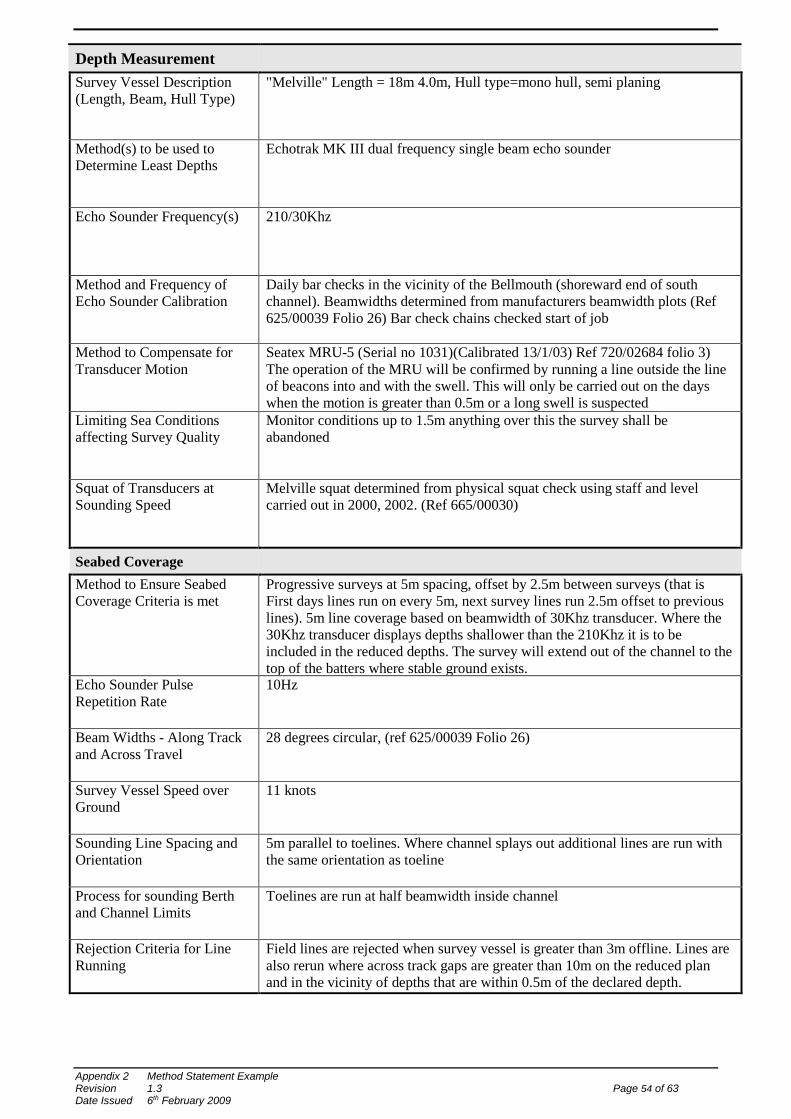
Depth Measurement
Survey Vessel Description (Length, Beam, Hull Type)
"Melville" Length = 18m 4.0m, Hull type=mono hull, semi planing
Method(s) to be used to Determine Least Depths
Echotrak MK III dual frequency single beam echo sounder
Echo Sounder Frequency(s)
210/30Khz
Method and Frequency of Echo Sounder Calibration
Daily bar checks in the vicinity of the Bellmouth (shoreward end of south channel). Beamwidths determined from manufacturers beamwidth plots (Ref 625/00039 Folio 26) Bar check chains checked start of job
Method to Compensate for Transducer Motion
Seatex MRU-5 (Serial no 1031)(Calibrated 13/1/03) Ref 720/02684 folio 3) The operation of the MRU will be confirmed by running a line outside the line of beacons into and with the swell. This will only be carried out on the days when the motion is greater than 0.5m or a long swell is suspected
Limiting Sea Conditions affecting Survey Quality
Monitor conditions up to 1.5m anything over this the survey shall be abandoned
Squat of Transducers at Sounding Speed
Melville squat determined from physical squat check using staff and level carried out in 2000, 2002. (Ref 665/00030)
Seabed Coverage Method to Ensure Seabed Coverage Criteria is met
Progressive surveys at 5m spacing, offset by 2.5m between surveys (that is First days lines run on every 5m, next survey lines run 2.5m offset to previous lines). 5m line coverage based on beamwidth of 30Khz transducer. Where the 30Khz transducer displays depths shallower than the 210Khz it is to be included in the reduced depths. The survey will extend out of the channel to the top of the batters where stable ground exists.
Echo Sounder Pulse Repetition Rate
10Hz
Beam Widths - Along Track and Across Travel
28 degrees circular, (ref 625/00039 Folio 26)
Survey Vessel Speed over Ground
11 knots
Sounding Line Spacing and Orientation
5m parallel to toelines. Where channel splays out additional lines are run with the same orientation as toeline
Process for sounding Berth and Channel Limits
Toelines are run at half beamwidth inside channel
Rejection Criteria for Line Running
Field lines are rejected when survey vessel is greater than 3m offline. Lines are also rerun where across track gaps are greater than 10m on the reduced plan and in the vicinity of depths that are within 0.5m of the declared depth.
Appendix 2 Method Statement Example Revision 1.3 Page 54 of 63 Date Issued 6th February 2009
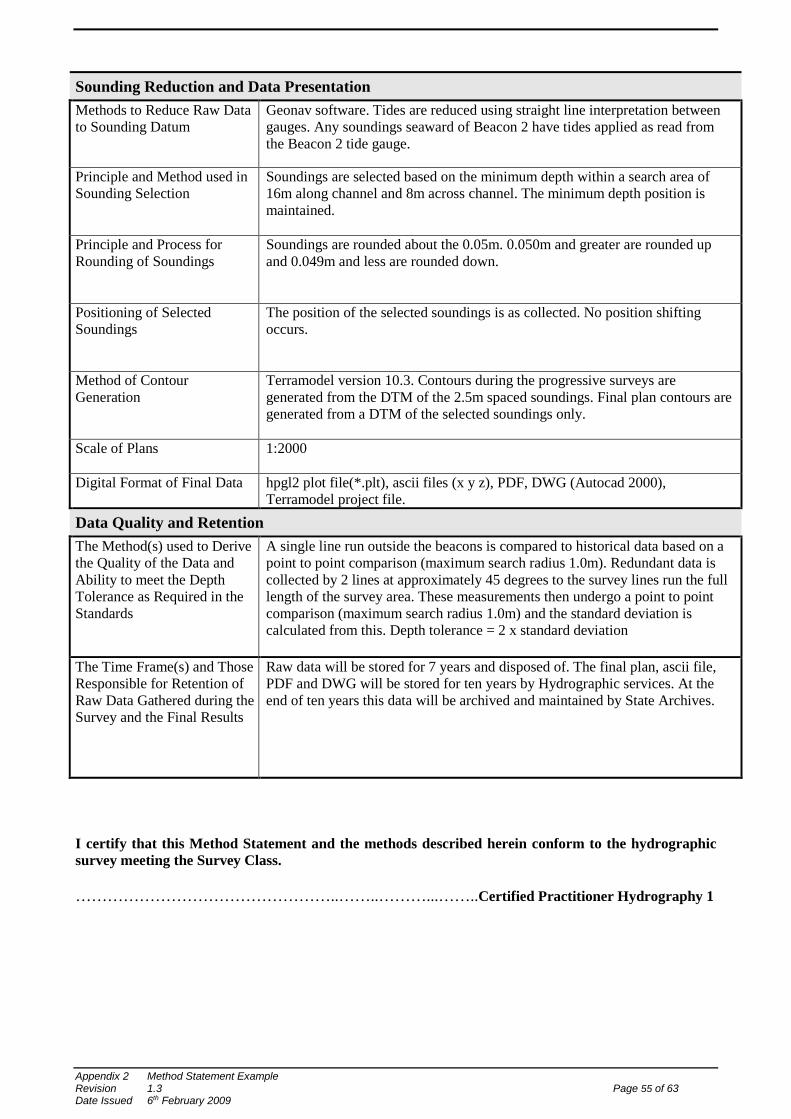
Sounding Reduction and Data Presentation Methods to Reduce Raw Data to Sounding Datum
Geonav software. Tides are reduced using straight line interpretation between gauges. Any soundings seaward of Beacon 2 have tides applied as read from the Beacon 2 tide gauge.
Principle and Method used in Sounding Selection
Soundings are selected based on the minimum depth within a search area of 16m along channel and 8m across channel. The minimum depth position is maintained.
Principle and Process for Rounding of Soundings
Soundings are rounded about the 0.05m. 0.050m and greater are rounded up and 0.049m and less are rounded down.
Positioning of Selected Soundings
The position of the selected soundings is as collected. No position shifting occurs.
Method of Contour Generation
Terramodel version 10.3. Contours during the progressive surveys are generated from the DTM of the 2.5m spaced soundings. Final plan contours are generated from a DTM of the selected soundings only.
Scale of Plans
1:2000
Digital Format of Final Data hpgl2 plot file(*.plt), ascii files (x y z), PDF, DWG (Autocad 2000), Terramodel project file.
Data Quality and Retention The Method(s) used to Derive the Quality of the Data and Ability to meet the Depth Tolerance as Required in the Standards
A single line run outside the beacons is compared to historical data based on a point to point comparison (maximum search radius 1.0m). Redundant data is collected by 2 lines at approximately 45 degrees to the survey lines run the full length of the survey area. These measurements then undergo a point to point comparison (maximum search radius 1.0m) and the standard deviation is calculated from this. Depth tolerance = 2 x standard deviation
The Time Frame(s) and Those Responsible for Retention of Raw Data Gathered during the Survey and the Final Results
Raw data will be stored for 7 years and disposed of. The final plan, ascii file, PDF and DWG will be stored for ten years by Hydrographic services. At the end of ten years this data will be archived and maintained by State Archives.
I certify that this Method Statement and the methods described herein conform to the hydrographic survey meeting the Survey Class. …………………………………………..……..………...……..Certified Practitioner Hydrography 1
Appendix 2 Method Statement Example Revision 1.3 Page 55 of 63 Date Issued 6th February 2009
APPENDIX 3 SURVEY REPORT
Document 630/046/008
Appendix 3 Survey Report Revision 1.3 Page 56 of 63 Date Issued 6th February 2009
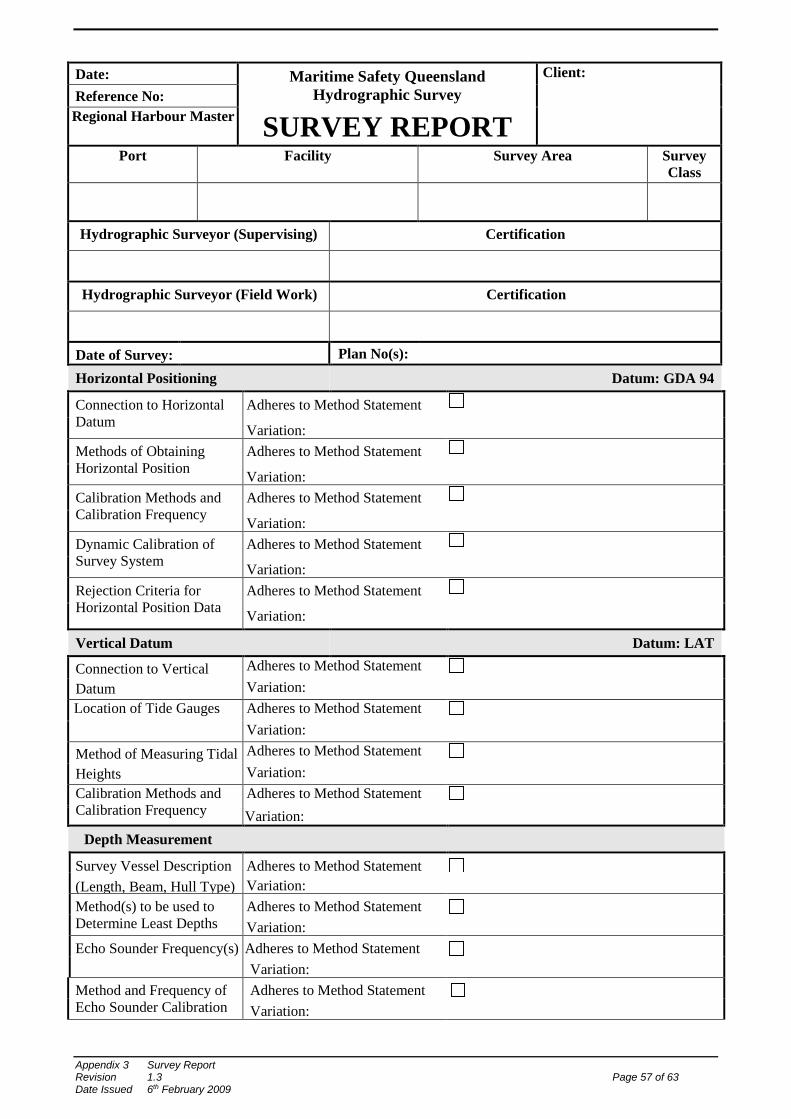
Date: Maritime Safety Queensland
Hydrographic Survey Client:
Reference No: Regional Harbour Master
SURVEY REPORT Port Facility Survey Area Survey
Class
Hydrographic Surveyor (Supervising) Certification
Hydrographic Surveyor (Field Work) Certification
Date of Survey: Plan No(s):
Horizontal Positioning Datum: GDA 94
Connection to Horizontal Datum
Adheres to Method Statement
Variation:
Methods of Obtaining Horizontal Position
Adheres to Method Statement
Variation:
Calibration Methods and Calibration Frequency
Adheres to Method Statement
Variation:
Dynamic Calibration of Survey System
Adheres to Method Statement
Variation:
Rejection Criteria for Horizontal Position Data
Adheres to Method Statement
Variation:
Vertical Datum Datum: LAT
Connection to Vertical Datum
Adheres to Method Statement Variation:
Location of Tide Gauges
Adheres to Method Statement Variation:
Method of Measuring Tidal Heights
Adheres to Method Statement Variation:
Calibration Methods and Calibration Frequency
Adheres to Method Statement Variation:
Depth Measurement
Survey Vessel Description (Length, Beam, Hull Type)
Adheres to Method Statement Variation:
Method(s) to be used to Determine Least Depths
Adheres to Method Statement Variation:
Echo Sounder Frequency(s) Adheres to Method Statement Variation:
Method and Frequency of Echo Sounder Calibration
Adheres to Method Statement Variation:
Appendix 3 Survey Report Revision 1.3 Page 57 of 63 Date Issued 6th February 2009
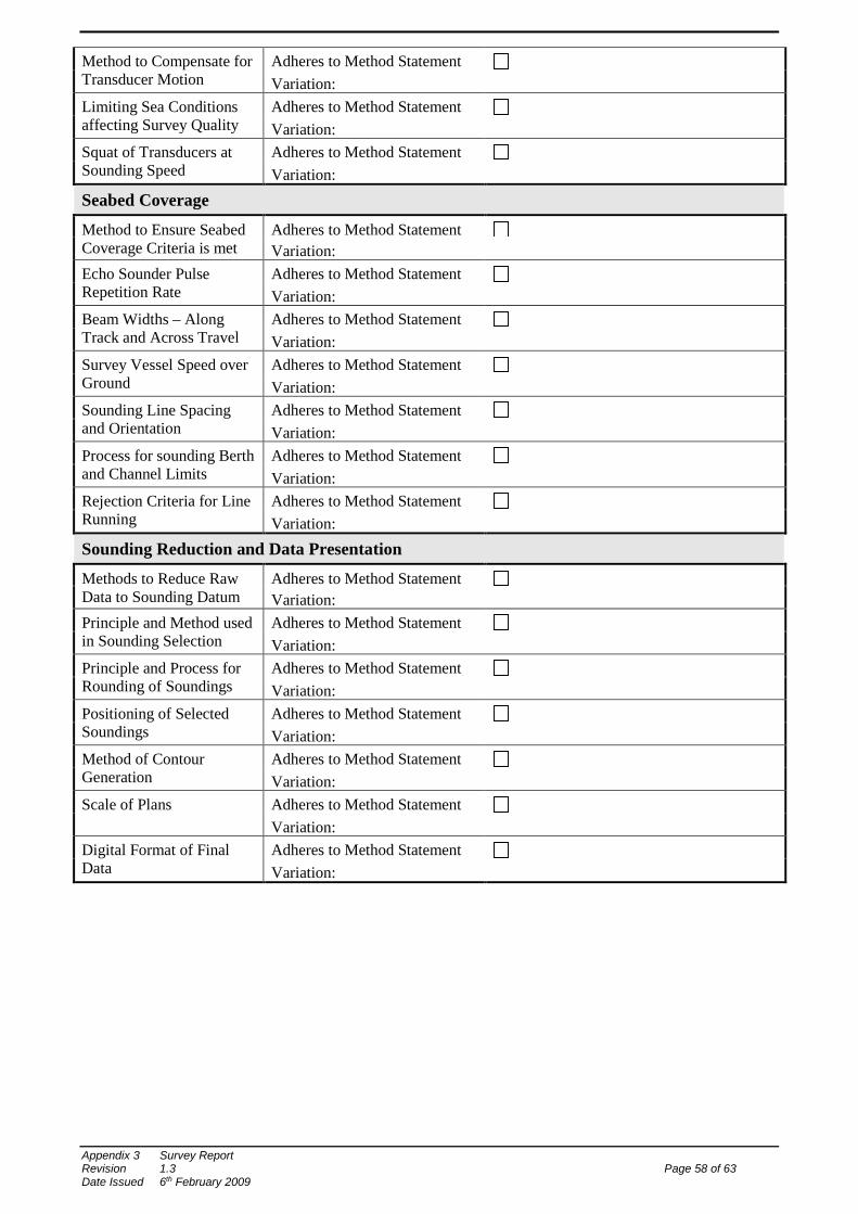
Method to Compensate for Transducer Motion
Adheres to Method Statement Variation:
Limiting Sea Conditions affecting Survey Quality
Adheres to Method Statement Variation:
Squat of Transducers at Sounding Speed
Adheres to Method Statement Variation:
Seabed Coverage
Method to Ensure Seabed Coverage Criteria is met
Adheres to Method Statement Variation:
Echo Sounder Pulse Repetition Rate
Adheres to Method Statement Variation:
Beam Widths – Along Track and Across Travel
Adheres to Method Statement Variation:
Survey Vessel Speed over Ground
Adheres to Method Statement Variation:
Sounding Line Spacing and Orientation
Adheres to Method Statement Variation:
Process for sounding Berth and Channel Limits
Adheres to Method Statement Variation:
Rejection Criteria for Line Running
Adheres to Method Statement Variation:
Sounding Reduction and Data Presentation
Methods to Reduce Raw Data to Sounding Datum
Adheres to Method Statement Variation:
Principle and Method used in Sounding Selection
Adheres to Method Statement Variation:
Principle and Process for Rounding of Soundings
Adheres to Method Statement Variation:
Positioning of Selected Soundings
Adheres to Method Statement Variation:
Method of Contour Generation
Adheres to Method Statement Variation:
Scale of Plans
Adheres to Method Statement Variation:
Digital Format of Final Data
Adheres to Method Statement Variation:
Appendix 3 Survey Report Revision 1.3 Page 58 of 63 Date Issued 6th February 2009
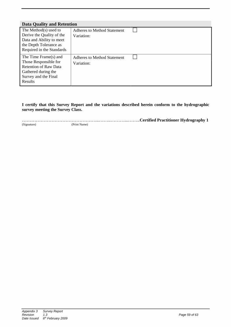
Data Quality and Retention The Method(s) used to Derive the Quality of the Data and Ability to meet the Depth Tolerance as Required in the Standards
Adheres to Method Statement Variation:
The Time Frame(s) and Those Responsible for Retention of Raw Data Gathered during the Survey and the Final Results
Adheres to Method Statement Variation:
I certify that this Survey Report and the variations described herein conform to the hydrographic survey meeting the Survey Class. …………………………………………..……..………...……..Certified Practitioner Hydrography 1 (Signature) (Print Name)
Appendix 3 Survey Report Revision 1.3 Page 59 of 63 Date Issued 6th February 2009