standards for dynamics in future electric energy systems · standards for dynamics in future...
TRANSCRIPT

STANDARDS FOR DYNAMICS IN FUTURE ELECTRIC ENERGY SYSTEMS
Marija Ilic [email protected] PSERC White Paper Webinar
May 22, 2012

Outline Four basic functionalities of standards for electric
energy systems Examples of problems related to lack of
standards for dynamics in today’s industry Summary of standardization efforts for smart
grids
Three possible approaches to standardization for dynamics
Illustrations using small examples
2

Four basic functionalities of standards for electric energy systems Standards must ensure safety of components; safety of
interactions among group of components; and safety of interactions of the system as a whole.
Standards must ensure that the electric energy system
continues to function as an interconnected AC system; further considerations are required to ensure that hybrid AC/DC interconnected systems are compatible and continue to function as a single interconnected system. System standards for interconnecting micro-grids, ranging from AC to all DC, to the bulk AC power system must be such that the hybrid AC/DC/AC system remains in synchronism.
3

Four basic functionalities of standards for electric energy systems (cont.) Standards must meet quality-of-service (QoS) as defined
by the (groups of) system users; in particular, sustained variations in frequency and voltage deviations seen by the system users (both producers and consumers) away from nominal must be maintained within the thresholds specified by the standards.
Dynamic standards must play the role of a powerful catalyst for integrating unconventional resources, demand response, and grid control technologies. Depending on the principles of their design, they could be standards and/or flexible, interactive, self-adapting protocols.
4
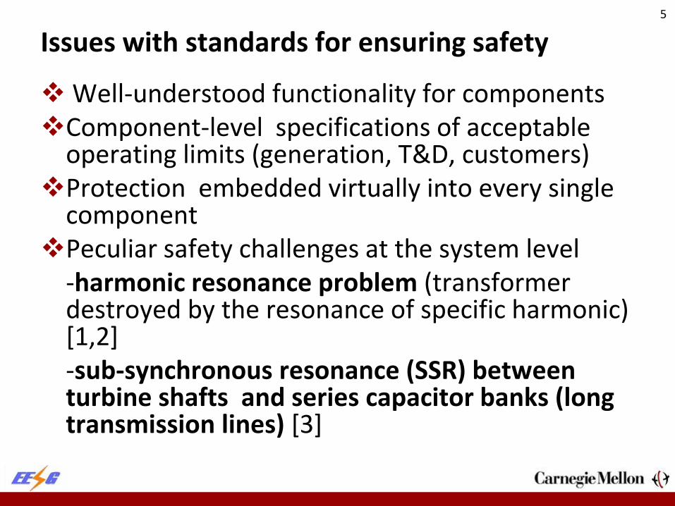
Issues with standards for ensuring safety
Well-understood functionality for components Component-level specifications of acceptable
operating limits (generation, T&D, customers) Protection embedded virtually into every single
component Peculiar safety challenges at the system level -harmonic resonance problem (transformer
destroyed by the resonance of specific harmonic) [1,2]
-sub-synchronous resonance (SSR) between turbine shafts and series capacitor banks (long transmission lines) [3]
5

Safety problems caused by harmonic resonance [1,2]
6
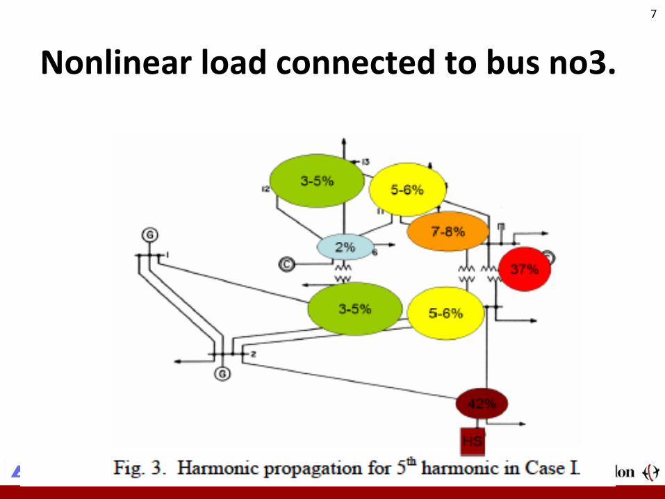
Nonlinear load connected to bus no3.
7

8

Harmonic source at bus 6
9

10

Harmonic source at bus 8
11

12

Transfer impedance as a metric of distortion propagation (network interactions)
13

14

Issues with safety standards for preventing harmonic resonance
Standards for avoiding system-level safety problems difficult to define System-dependent; disturbance-dependent. Should the standard for preventing harmonic
resonance-related safety problems require filters at the source of harmonics only? Should the standard for preventing harmonic
resonance-related safety problems be system dependent?
15
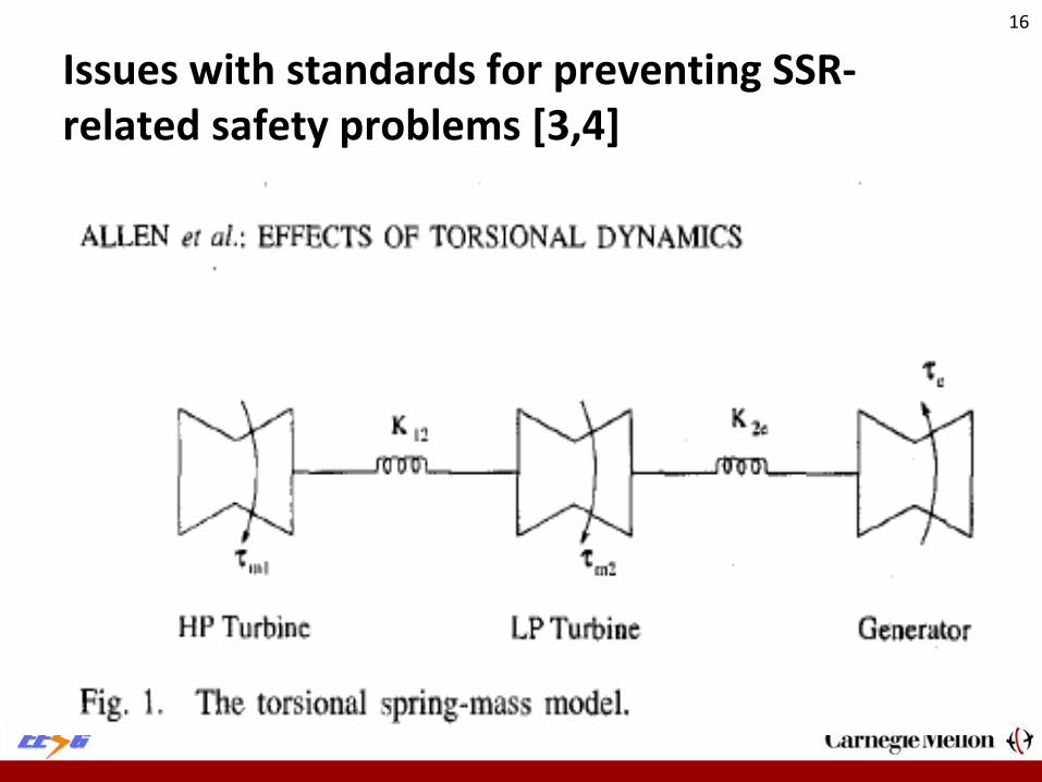
Issues with standards for preventing SSR-related safety problems [3,4]
16

Modeling matters..
17

18

Shaft acceleration
19

20

21

22

Clever control (FBLC) makes the difference…
23
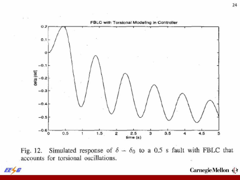
24

25

High-gain control for preventing SSR
26

Huge issues with SSR-related safety
Protection for avoiding SSR problem versus closed-loop control design for decoupling interactions between different components.
It is much more effective not to limit the line parameters. Protection for SSR at its infancy, and has worse
performance than nonlinear decentralized FBLC for Efd of a generator.
High-gain power electronically-controlled SSR very beneficial in this case.
The key challenge: How to set the ``best” standard to induce its deployment instead of using protection for disconnecting the affected component.
27

Issues with standards for ensuring AC synchronism Many root causes of instabilities in today’s
industry (large equipment failures, large deviations in system load away from the conditions for which the primary controllers are tuned) [5,6] Newly evolving transient stability problems
in response to sudden prolonged wind gusts [7,8] Small-signal robustness problems [9,10]
28

29
29
30
Possible role of enhanced control during abnormal conditions [5,6]
Adjust logic of primary controllers to avoid
instability problems; Systematic coordination of the remaining
resources to prevent steady-state imbalances and additional congestion (adjust settings on voltage support equipment, adjust power generated to avoid imbalances) [12]
30

31
Potential of novel stabilizing controllers for preserving system integrity [5,6]
A 38-bus, 29 machine equivalent dynamic model of the NPCC system
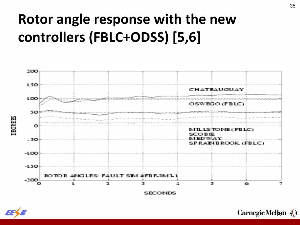
It was shown to reproduce a multi-machine oscillation that occurred at .75Hz, involving groups of machines in NYC (modeled as Sprainbrook generator) and the northeastern part of New York State, as well as parts of Canadian power system (modelled primarily by the Oswego and Chateaguay units);
The fault scenario selected for this test was a five-cycle three-phase short circuit of the Selkrik/Oswego transmission line carrying 1083MW. The oscillation grows until the Chateaguay generator loses synchronism, followed shortly by the Oswego unit.
31

32
Rotor angles -- base case for Selkrik fault
32

33
Voltage response with conventional controllers-base case Selkrik fault
33

34
Bus voltages with new controllers [5,6]
34
35
Rotor angle response with the new controllers (FBLC+ODSS) [5,6]
35

36
Summary of potential of FBLC+ ODSS controllers
It is possible that these controllers could avoid loss of synchronism while the conventional controllers can not
It also was shown that the same controllers are ideal for preventing sub-synchronous resonance [3]
Therefore critical to consider while designing SPS of the future
No fast communications required. Therefore simple to implement.
36

37
Possible ways of adapting primary controllers More adaptive decentralized controllers (various nonlinear
high-gain controllers—sliding mode control; feedback-linearizing control (FBLC); observation decoupled state space combined with FBLC logic)
A combination of coordinating signals and change of logic (coordinating signals identifying when the system response is qualitatively different and it requires change in control logic in order to stabilize dynamics)
NONE OF THE CURRENTLY IMPLEMENTED CONTROLLERS ARE CURRENTLY AFDAPTIVE except the multi-modal Hydro-Quebec PSS)
37
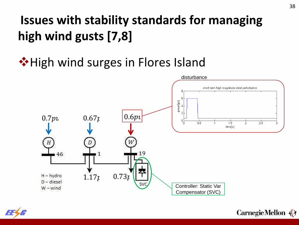
Issues with stability standards for managing high wind gusts [7,8]
High wind surges in Flores Island
Controller: Static Var Compensator (SVC)
disturbance
38

Stabilization using high-gain switching
Hydro Diesel Wind Other control strategies
Total accumulated energy and energy accumulated in wires
Rotational frequency, active power output of the three generators and bus voltage magnitudes
39

Energy-Based controller is proposed Temporarily accumulates
energy of disturbance in PE devices
Modeling & Control
Use of time varying phasors for transmission line and FACTS modeling to Capture fast
dynamics Establish ODE model
Assume fast PE thyristor switching – averaged switching model
40

Sliding Mode Control of Flywheel 41
Treat the rest of the system as a disturbance Set ,so flywheel absorbs wind disturbance * 2 wind
qsm f
PiNλ ω∆
=

Dynamic Model of Entire System 42
Switches open and close at very high frequency relative to rest of the grid Fast time scale t and slow time-scale τ Using state space averaging,
( ) cs cscs
v t v tvt t
τ+ + − −
+ −
+=
+
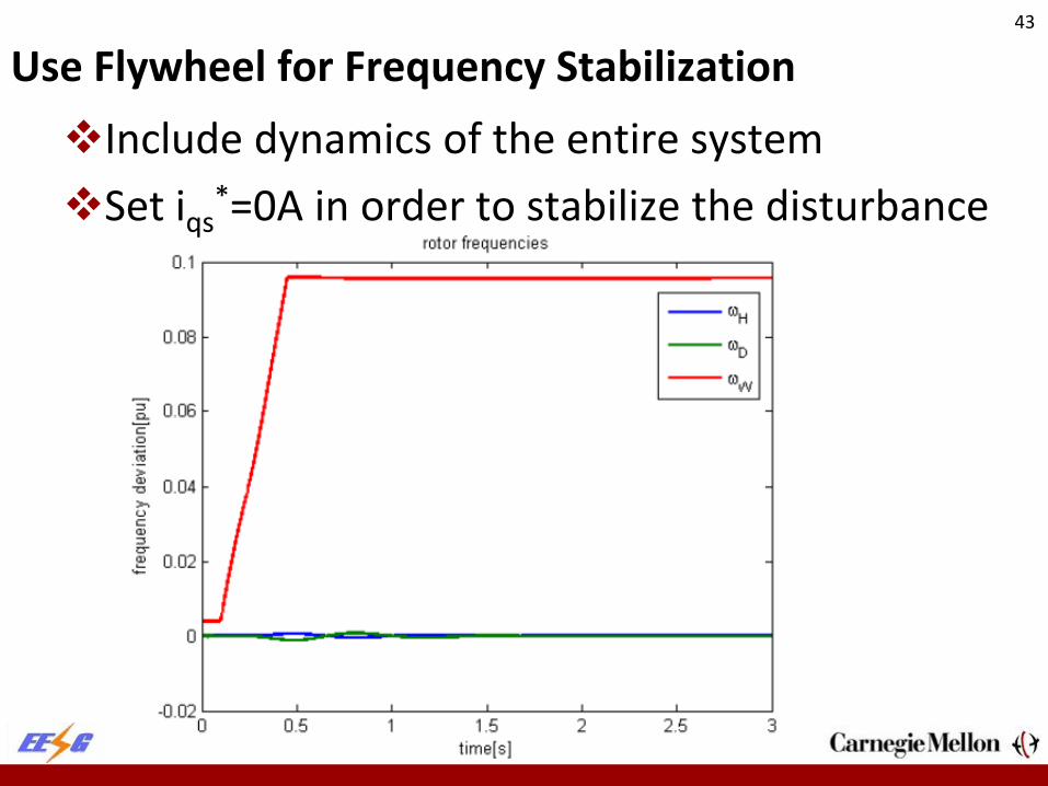
Use Flywheel for Frequency Stabilization Include dynamics of the entire system Set iqs
*=0A in order to stabilize the disturbance
43

Issues with small signal stability [9-11] Today’s approach is to tune individual primary
controllers (governors, DFIG of wind power plants, excitation systems) so that they are stand-alone stable for the assumed ``worst-case” system condition.
All controllers are constant gain decentralized PID controllers responding to the local output variables (voltage magnitude, frequency).
No reliance on communications. Small signal stability analysis run for the closed-loop
system dynamics to ensure that linearized system dynamics are stable.
Missed opportunity to design PMU-based primary control for ensuring small signal stabilization (with minimal communications).
44

Flores island system
45

Critical role of primary control
Unstable Flores System without Governor and Excitation Control
46

Issue with stability with strictly decentralized control
Unstable system with decentralized control
47
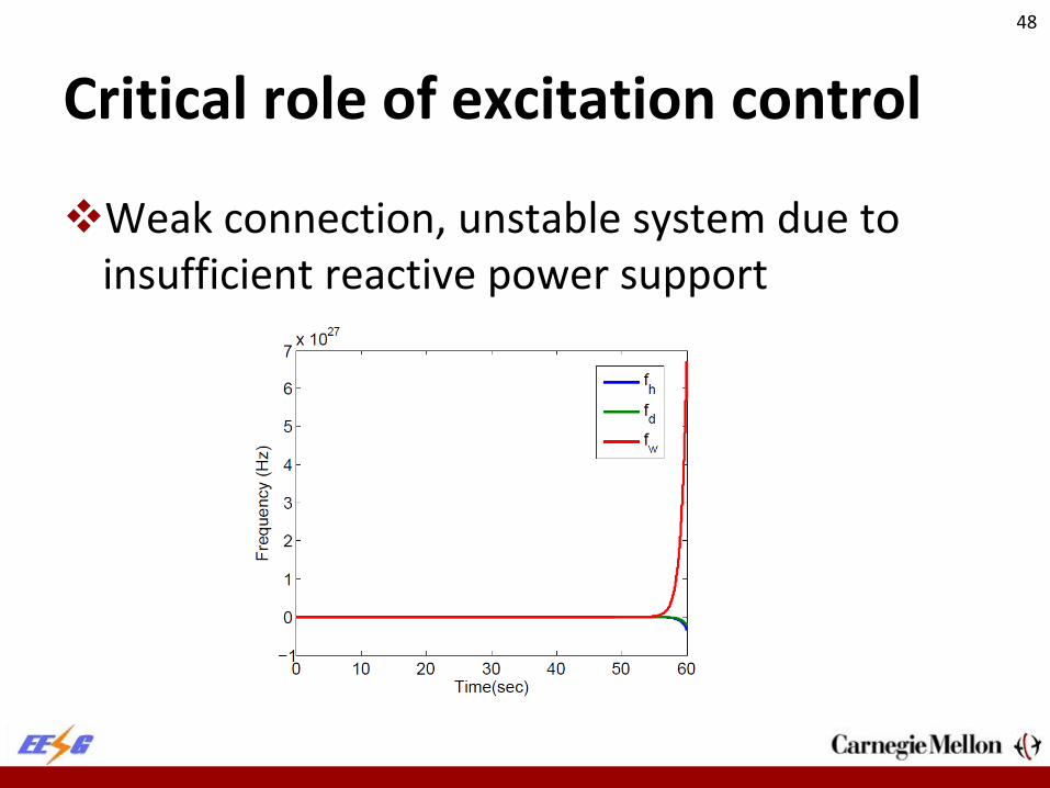
Critical role of excitation control
Weak connection, unstable system due to insufficient reactive power support
48

Dynamics of interaction variables— Sao Miguel System
[2] M. Ilic “The Tale of Two Green Islands in the Azores Archipelago,” Chapter 2 of Engineering IT-Enabled Sustainable Electricity Services : The Tale of Two Low-Cost Green Azores Islands.
49

Key notion of interaction variable dynamics and their control Interactions variables of area-1 and area-2
50

Controlled IntV v.s. uncontrolled IntV
51

Issues with intra-area dynamics
Other states [still oscillations]
52

No issues with QoS in today’s industry—well-understood standards [15]
G1 G2
L12
G3
B1 B2 B3
B4 B5
G4
L11
L21Area 2 Area 1
G1 and G2: Hydro Generators; droop1 = 0.03, droop2 = 0.025 G3 and G4: Combustion-turbine Generators; droop3 = 0.05, droop4 = 0.06
53

Key assumptions of AGC
Steady-state assumption Uniform frequency across the system Frequency biases are tuned so that
β: frequency bias σ: speed droop D: damping Kt: control gain of the speed-governor r : parameters of the speed-governor
54

Issues with QoS in the changing industry [9-11]
Technology-dependent droop characteristics Frequency deviations harder to differentiate
than power (or angles) –NEED TO THINK MUCH MORE ABOUT THE IMPLICATIONS OF THIS! Back to continuous carefully designed
reduced order models which can be used to systematically design an LQR for meeting pre-specified performance metrics (cost vs quality of regulation)
55
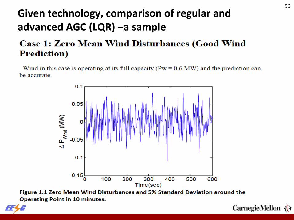
Given technology, comparison of regular and advanced AGC (LQR) –a sample
56

57

58

59

60

61

Issues with QoS for voltage
62
Scheduled load value and the disturbance around the value
0 20 40 60 80 100 120 140 160 180
20.3
20.4
20.5
20.6
20.7
20.8
20.9
21
21.1
Time (mins)
Load
Rea
ctiv
e P
ower
Evo
lutio
n (p
.u.)
NYISO August 2006 Load Data for 3 Hours, Power Factor = 0.8
0 20 40 60 80 100 120 140 160 18015
16
17
18
19
20
21
22
23
24
Time (mins)
Load
Rea
ctiv
e P
ower
Evo
lutio
n (p
.u.)
NYISO August 2006 Load Reactive Power Data for 3 Hours, Measurement Frequency = 0.50 Hz,Power Factor = 0.8
Pre-planed Load ValueReal Load Evolution, with 0.5Hz Sampling
62

AVC for the NPCC with PMUs
63
Simulations to show the worst voltage deviations in response to the reactive power load fluctuations (3 hours)
0 20 40 60 80 100 120 140 160 1800
0.01
0.02
0.03
0.04
0.05
0.06
0.07
0.08
0.09
0.1
Time (min)
Sys
tem
Wor
st V
olta
ge D
evia
tion
(p.u
.)
1 Pilot Point Secondary Voltage Control with Measurement Frequency = 0.50 Hz,Power Factor = 0.8
No ControlOne Pilot Point per Area5% Criteria
0 20 40 60 80 100 120 140 160 1800
0.01
0.02
0.03
0.04
0.05
0.06
0.07
0.08
0.09
0.1
Time (min)
Sys
tem
Wor
st V
olta
ge D
evia
tion
(p.u
.)
2 Pilot Points Secondary Voltage Control with Measurement Frequency = 0.50 Hz,Power Factor = 0.8
No ControlTwo Pilot Point per Area5% Criteria
2 Pilot Points Control Performs Better Than 1 Pilot Point!
63

Use of on-line fast and accurate measurements—Future [12]
64
PMU Control
Constrained Line Line-to-Ground Clearance Transfer Capacity in Real
Time
DLR
64

Northeastern Power Coordinating Council (NPCC) System
65
Take NPCC system as ONE AREA; then put 1, 2 and 3 PMUs at pilot buses [13]
One Area, One PMU Graph
65

Implications on standards for dynamics?
The line between standards for safety, ensuring QoS and for avoiding stability problems not well defined.
The more advanced decentralized control, the less need for fast communications.
An important observation for possible path ahead: Effective decentralized control for preventing SSR and for preventing low-frequency inter-area oscillations have one common feature: They require lots of effort to cancel interactions with the rest of the system.
66
Standardization efforts for smart grids Smart grids are targeted to enabling alignment
of temporal and spatial characteristics of resources and users by means of a man-made electric power grid and its IT
Critical to have standardized characterization of system components;
Common Information Model (CIM) –primarily for steady-state characteristics of system components; major effort
Recent efforts for establishing CIM for dynamic characterization of components; work in progress.
67

“Smart Grid” electric power grid and IT for sustainable energy SES [14]
Energy SES
• Resource system (RS)
• Generation (RUs)
• Electric Energy Users (Us)
Man-made Grid
• Physical network connecting energy generation and consumers
• Needed to implement interactions
Man-made IT
• Sensors • Communications • Operations • Decisions and
control • Protection
68

Model-based IT for Smart Grids Dynamic models to monitor, communicate and
control dynamic interactions within a smart system so that resources, users’ preferences and governance are aligned temporally and spatially as much as possible.
One could view the role of standards for dynamics as the basic means of defining what needs to be sensed, communicated and controlled so that desired closed-loop dynamics is achieved.
Standards need to be defined at the component level, control area level and at the interconnection levels.
Non-unique ways of achieving system-level dynamic performance.
69

Possible approaches to standards for dynamics Essential for avoiding emerging behavior in future
electric energy systems Major questions concerning limits on control and type
of control and communications required. Enhanced sensing, communications and control will
reduce the need for stand-by (real power) generation reserve.
Each (group of) components must be responsible for safe and stable interactions with the neighboring control areas at the pre-specified QoS –smart balancing authorities (SBAs); this is a direct generalization of control areas.
70

Three qualitatively different paradigms for standardization of dynamics in future smart grids
Plug-and-play standards for dynamics, with no requirements for on-line communications. Much stricter standards at the component level will be needed for this to work.
System-level technical standards based on minimal coordination of decentralized component-level standards.
Interactive protocols for ensuring technical performance according to choice and at value)—dynamic monitoring and decision systems (DYMONDS).
71

Major differences
Plug-and-play standards for dynamics –enhanced decentralized control for internalizing effects of interactions and canceling them. Lots of advanced local control.
Standards based on minimal coordinated control of interaction variables for given nested architecture of future electric energy systems. Technical specifications at the decentralized level, economic and technical specifications at the system level. Minimal exchange of technical signals.
Interactive protocols in terms of interaction variables evolving dynamically over time and space according to system users’ preferences. Both economic and technical specifications at all levels. Minimal exchange of technical and economic signals.
STRUCTURE-BASED AND PROVABLE DYNAMIC PERFORMANCE.
72

DYMONDS-enabled Physical Grid [14] 73

Multi-layered smart balancing authorities [14]
74

References [1] Private correspondence with Dale Osborn, MISO. [2] Talaat, Nermeen and Marija D. Ilic. "ANNs Based on Subractive Cluster Feature for Classifying
Power Quality Disturbances." 2008 North American Power Symposium (NAPS 2008), September 28-30, 2008. Calgary, Canada.
[3] Allen, E.H., J.W. Chapman and M.D. Ilic, "Effects of Torsional Dynamics on Nonlinear Generator Control," IEEE Transactions on Control Systems Technology, 4, 125-140, March 1996.
[4] IEEE SSR Task Force of the Dynamic System Performance WG: First benchmark model for computer simulations of SSR, IEEE Trans. 1977, pp. 1565-1572.
[5] M.D. Ilic and J.W. Chapman, "Decentralized Excitation Control for an Electrical Power Utility System," U.S. patent number 5 483 147, 1996.
[6] M.D. Ilic and S.X. Liu, "Direct Control of Inter-area Dynamics in Large Power Systems Using Flexible AC Transmission Systems (FACTS) Technology," U.S. patent 5 517 422, 1996.
[7] Cvetkovic, Milos, and Marija Ilic, Nonlinear Control for Stabilizing Power Systems During Major Disturbances, IFAC World Congress, Milano, August 2011.
[8] Cvetkovic, Milos, Bachovchin, Kevin and Marija Ilic, Chapter 19 in Ilic, M., Xie, Le and Liu, Qixing (editors), Engineering IT-Enabled Sustainable Electricity Services : The Tale of Two Low-Cost Green Azores Island, Springer, 2012 (to appear) .
[9] Q. Liu, M. Cvetkovic, and M. Ilic “Toward Stabilizing Linearized System Dynamics in Future Electric Energy Systems by Means of Enhanced Voltage Control,” Chapter 16 in Engineering IT-Enabled Sustainable Electricity Services : The Tale of Two Low-Cost Green Azores Islands, Springer, 2012 (to appear) .
75

References (cont.) [10] Ilic, M and Liu, Qixing, Toward Sensing, Control and Communications for Frequency
Regulation in Systems with Highly Variable Resources, in Control and Optimization Methods for Smart Grids, Springer 2012, Chapter 1.
[11] Popli, Nipun and Ilic, M, Chapter 14 in Engineering IT-Enabled Sustainable Electricity Services : The Tale of Two Low-Cost Green Azores Islands, Springer, 2012 (to appear).
[12] Ilic, M., E. Allen, J. Chapman, C. King, J. Lang, and E. Litvinov. “Preventing Future Blackouts by Means of Enhanced Electric Power Systems Control: From Complexity to Order.” IEEE Proceedings, November 2005.
[13] Ilic, Marija and Liu, Zhijian, ``A New Method for Selecting Best Locations of PMUs for Robust Automatic Voltage Control (AVC) and Automatic Flow Control (AFC)”, IEEE PES 2010, Minneapolis, MN, July 25-29, 2010.
[14] Ilic, M., Dynamic Monitoring and Decision Systems for Sustainable Electric Energy, Proc of the IEEE, Jan 2011.
[15] Ilic, M., Smart Grid and Future Electric Energy Systems, Lecture Notes, 18-618, Carnegie Mellon Univ, ECE, Spring 2012.
76