standardized intakes and outlets for low-head …several standard "off the shelf" units...
TRANSCRIPT

HYDRAULICS BRANCH OFFICIAL FILE COPY
PAP-453 BUREAU OF RECLAMATION
DOE-79-01 HYDRAULICS BRANCH
OFFICE FILE COPY
When Borrowed Return Promptly
STANDARDIZED INTAKES AND
OUTLETS FOR LOW-HEAD
HYDROPOWER DEVELOPMENTS
CLIFFORD A. PUGH


ACKNOWLEDGMENTS
This report was prepared under agreement EG-77-A-36-1024 by the Bureau of Reclamation for the Department of Energy. The report was reviewed by T. J. Rhone, Head, Applied Hydraulics Section, D. L. King, Chief, Hydraulics Branch, and Dr. Ing. H. T. Falvey, Technical Specialist, Hydraulics Branch in the Division of Research.
Some of the information used in the report was provided by the following companies:
1. Harza Engineering Company 2. International Engineering Company 3. Allis -Chalmers 4. Motor Columbus Consulting Engineers, Inc. 5. F.W.E. Stapenhorst, Inc. 6. Fuji Electric Company, Ltd. 7. Escher Wyss, Ltd. 8. Public Utility District No. 1 of Chelan County, Washington 9. Karlstads Mekaniska Werkstad 10. Swedish Power Association
The contributions and cooperation of these companies are sincerely appreciated.

t
0
I

Disclaimer
The contents of this report are not to be used for promotional purposes. Citation of a trade name or company does not constitute an official endorsement by the Bureau of Reclamation, nor does it imply that these are the only manufacturers or consultants offering products or services in the low-head hydropower field.

if
ABSTRACT
This report presents the results of a state-of-the-art review performed to investigate the present status of standardization of flow passage design for low-head hydropower developments. The current design practices regarding flow passages are summarized and examined to determine if improvements could be made to reduce losses or simplify present design without introducing significant additional losses.
Several standard "off the shelf" units are currently available in the low-head range (less than 20 m). Standard axial flow tube and bulb units and cross flow turbines can be obtained in the range from 50 kW to 5000 kW. These predesigned units reduce equipment costs by eliminating the need for site-specific engineering and by using standardized manufacturing techniques. However, these savings are often obtained at the expense of a slight loss in unit efficiency. Manufacturer's drawings with standard flow passage dimensions for bulb and rim-generator units are included.
Most designers and consultants feel that standardization of flow passage design is not feasible. Structural and geological considera- tions often affect the design. However, a manual to aid in the planning and design,of flow passages is considered to be worthwhile. An alternative to standardization of flow passages in general would be to develop a standardized design for a series of powerplants to be installed at similar locations. An example of this approach is the proposed harnessing of the Rhine River upstream of Lake Constance. Research regarding the effect of intake shape, boundary layer control in the draft tube, and rate of rise of the exit channel in the tailrace may lead to simplified designs and reduced construction costs. Fifty-two references on the design of flow passages and the advantages of low-head hydropower are cited.
Key words and identifiers: flow passage design/ intakes/ draft tubes vortices standardization/ low-head hydropower/ axial flow turbines/ standardized designs/ forebay/ tailrace/ bulb turbines/ tube turbines/ rim generator turbines/ turbine setting

G
•a•

CONTENTS
Paae
I. Purpose and Scope
A. Purpose . . . . . . . . . . . . . . . . . . . . . . . 1 B. Scope . . . . . . . . . . . . . . . . . . . . . . . . 2
II. Conclusions and Recommendations
,. A. Conclusions . . . . . . . . . . . . . . . . . . . . . 3 B. Recommendations . . . . . . . . . . % . . . . . . . . 4
III. Introduction
A. Kaplan Turbines . . . . . . . . . . . . . . . . . . . 6 B. Axial Flow Turbines . . . . . . . . . . . . . . . . . 6
1. Rim-generator turbine . . . . . . . . . . . . . . 6 2. Tube turbine . . . . . . . . . . . . . . . . . . . 8
.3. Bulb turbine . . . . . . . . . . . . . . . . . . . 9
IV. Status of Standardization
A. Standard "Off the Shelf" Units. . . . . . . . . . 11
1. Tube turbines . . . . . . . . . . . . . . . . . . 11 2. Bulb turbines . . . . . . . . . . . . . . . . . . 11 3. Cross flow Turbines . . . . . . . . . . . . . . . 15 4. Small high-head turbines . . . . . . . . . . . . 16
B. Standard Dimensions 16 C. Standard Designs for a Line of Turbines . . . 16 D. Mini Power Stations in Sweden . . . . . . . . . . . 22 E. Comments on Standardization . . . . . . . . . . . . . 24
V. Current Design Practices
A. Forebay . . . . . . . . . . . . . . . . . . . . . . . 25 B. Intake . . . . . . . . . . . . . . . . . . . . . . . 25
1. Vortex formation . . . . . . . . . . . . . . . . . 25 2. Pier design . . . . . . . . . . . . . . . . . . . . 28 3. Trashrack design . . . . . . . . . . . . . . . . . 30 4. Intake shape . . . . . . . . . . . . . . . . . . . 31 5. Fish passage allowances . . . . . . . . . . . . . 31

Contents - Continued
C. Runner Diameter and Turbine Setting . . . . . . . . . 31 D. Draft Tube . . . . . . . . . . . . . . . . . . . . . 33 E. Tailrace . . . . . . . . . . . . . . . . . . . . . . . 38
VI. General Comments
A. Tidal Power . . . . . . . . . . . . . . . . . . . . . 39 B. General References . . . . . . . . . . . . . . . . . 39
Bibliography . . . . . . . . . . . . . . . . . . . . . . . . 40

LIST OF FIGURES
Figure Page
1 Kaplan turbine . . . . . . . . . . . . . . . . . . . . 5 2 Rim-generator turbine . . . . . . . . . . . . . . . . 7 3 Tube turbine . . . . . . . . . . . . . . . . . . . . . 8 4 Bulb turbine 9 5 Rock Island Dam - bulb turbines . . . . . . . . 10 6 Standard tube turbines (Allis-Chalmers) . 12 7 Standard tube turbine (Karlstads Mekaniska Werkstad) 13 8 Standard bulb turbine (Fuji) . . . . . . . . . . . . 14 9 Cross flow turbine (Ossberger) . . . . . . 15 10 Bulb turbine - standard flow passage (Escher Wyss) 17 11 Rim generator turbine - standard flow passage -
(Escher Wyss). . . . . . . . . . . . . 18 12 Bulb turbine - standard flow passage dimensions
(Fuji) . . . . . . . . . . . . . . 19 13 Bulb turbine - consensus configuration (IECO) . . . . 20 14 Rhine River standard bulb turbine layout (Motor-
Columbus Consulting Engineers) . .
. . . . . 21 15 Types of mini power station in Sweden (reference 7) 23 16 General configuration for vortex study (reference 8) 26 17 Minimum submergence (reference 8). . . . . . . . . . . 26 18 Vortex severity vs. Froude and Reynolds numbers
(reference 10) . . . . . . 27 19a Flow separating pier between powerhouse and
weir (reference 51). 29 19b Pier nose shapes (HDC) (referenW 12*). . 29 20 Runner diameter design chart (reference 14). . . . . . 32 21 Tubular (AXIAL FLOW)
Turbine diameter vs. Hp (reference 15) . 34 H
22 Possible methods for shortening draft tubes (reference 18) . . . .
23 Energy balances in two turbine operating modes (reference 23) 37
24 Waterway configuration of model bulb turbine (reference 23) . . . . . . . . . . . . . . . . . . . 37

r.

I. PURPOSE AND SCOPE
A. Purpose
The objective of standardization is to reduce the cost of low-head hydropower. The main purpose of this phase of the study was to determine the present status of standardization of flow passages and to determine if stancardization is a feasible means of reducing the cost of low-head structures. Another objective was to examine current design practices to identify areas where design changes or further research could result in less costly structures.
The need for additional energy production combined with diminishing reserves of fossil fuels has resulted in a need to develop the remaining hydropower capacity in the United States. There are many existing impoundments and completely undeveloped sites that could be developed with little effect on the environment. There are also many sites in need of updating. Additional generating units ana replacement of obsolete equipment could significantly increase power generation from these sites. At the same time coal-fired and nuclear powerplants face an uncertain future because of environmental concerns and lengthy licensing procedures. Low-head hydropower could make a substantial contribution to help gap the predicted energy shortage in the next 10 years.
The main obstacle to development of low-head sites (heads below 20 m) has been economics. The cost per kWh for low-head hydropower is still slightly higher than is for fossil fuel plants. However, with the cost of fuels continuing to rise, the low-head hydropower alternative is becoming more favorable.
In low-head plants, the head losses could reduce the net effective head by a significant portion of the total available energy. There-fore, it would be desirable to streamline the flow passages as much as possible to minimize the head losses. At the same time, economics dictate that the flow passage shape be as simple as possible. With these conflicting interests in mind, the present design methods were examined to determine possible design improvements to further reduce losses or to simplify present designs without introducing significant additional losses.
The design of penstock entrances for high-head dams is one example that illustrates the value of taking a closer look at conventional design practices. It was conservatively estimated that $13 million was saved in construction costs on the penstock entrances for the Third Powerplant at Grand Coulee by reducing the size of the bellmouth entrances (reference 1). Penstock entrances had historically been designed using the same criteria used in designing high-velocity conduits

while the velocity in penstocks is much lower. Hydraulic model studies indicated that losses were actually lower in the smaller entrance. The same criteria used to design high-velocity conduits are used to design intake shapes for low-head plants. Therefore, savings may be possible by changing design methods in low-head structures.
B. Scope
The work during the first year of this study included a literature review and contacts with manufacturers, consultants, and operators of loy,-head turbines.
The flow passage studies included:
1. The forebay - which controls the flow approaching the intake.
2. The intake - which accelerates the flow to the turbine.
3. The draft tube - which decelerates the flow to recover the kinetic energy in the flow.
4. The tailrace which carries the flow away from the turbines.
2
II. CONCLUSIONS AND RECOMMENDATIONS
A. Conclusions
1. Complete standardization of flow passages for low-head hydropower developments is not feasible. Structural and geological considerations may cause design variations from site to site. This would cause the flow passage designs to vary. The differences would be more evident in large installations.
2. "Off the shelf" units are presently available for small -plants. These units have standard flow passages included. The low cost resulting from standardization is achieved at the expense of some loss in efficiency. However, the cost savings are significant, especially if several installations are considered as a group.
3. Standardized designs are feasible for similar site character-istics. For large installations, these standard designs should be as efficient as practicable, since in low-head plants the hydraulic losses represent a signficant portion of the total available head. Where geologic and structural considerations do not vary widely the same design may be used for a series of installations thus reducing the costs associated with site-specific engineering and design.
4. The hydraulic design of the draft tube is customarily determined by the manufacturer, since it is considered an integral part of the turbine in determining turbine performance. Results of model tests done by manufacturers optimizing flow passage dimensions are not publicly available. However, modern techniques of boundary layer control may be useful in shortening draft tubes,.thus con-siderably reducing construction costs. The possibility of reducing draft tube lengths through boundary layer control has not been investigated.
5. Intake shape is typically determined using design criteria for high velocity conduit entrances. It is possible that intake shapes may be reduced in size or simplified without a significant loss in efficiency.
6. The effect on turbine efficiency of the rate of rise in the channel bottom in the tailrace is not known. A steep rise may cause flucuations in the tailwater level and reduce turbine efficiency.
3

B. Recommendations
1. Investigate the effect that simplifying the intake shape and varying the rate of rise in the channel bottom might have on the hydraulic losses in low-head turbine flow passages.
2. Investigate the effect on the contraction coefficient of the shape of the flow separating pier between the powerhouse and weir and the pier between adjacent bays in the powerhouse.
3. Investigate the use of boundary layer control in draft tubes to-shorten the length of draft tube required while maintaining hydraulic efficiency.
4. Evaluate the potential economic benefits which could result from design changes in the intake, draft tube, and tailrace.
5. Prepare a design manual to serve as a guide in the design of intake and exit structures for various types of low-head turbines under various operating conditions. This guide would promote the use of low-head hydropower and possibly present alternate design methods which could reduce the cost of the civil works. Some manufacturers and designers may resist a publication presenting design methods that conflict with their present practices. However, if economically marginal projects are made feasible by cost reductions in the civil works the turbine manufacturers and designers could benefit from the additional business that would be generated.
4

'i
i
.' a r• ..: :~.-_
''. •.0•~~
O :•: "D•.•. I
VERTICAL KAPLAN TURBINE ESCHER WYSS
FIGURE /
5

III. INTRODUCTION
A. Kaplan Turbines
In the head range between 3 and 45 m, turbines with propeller-type runners are typically used (reference 2). If the runners are adjustable, the turbines are called "Kaplan turbines." These turbines are usually arranged with a vertical shaft, a spiral case, and an elbow-type draft tube (figure 1). A large percentage of present low-head turbines are this type. However, at heads less than 20 m, axial flow turbines have proved to be more economical. This.study is mainly concerned with the low-head range, less than 20 m, although some material on small high-head turbines is also included.
B. Axial Flow Turbines
Turbines in which the water is conducted to the distributor coaxially i with the shaft are called "axial flow turbines" or sometimes "tubular turbines" (reference 2). To avoid confusion, the term "axial flow turbine" will be used in this report. Axial flow turbines also use propeller-type runners. In some cases, adjustable (Kaplan) runners are used.
Axial flow turbines do not have a spiral case or elbow-type draft tube. They are slightly more efficient hydraulically since there are fewer bends in the flow passage. A report on "Low-Head Power Generation With Bulb Turbines" (reference 2) compares an axial flow turbine with a vertical Kaplan turbine at a specific site. The net head was 5.8 m and rated output was 7.2 MW for each unit. The report concluded that the main advantage of the axial flow turbine was the large savings in construction costs. Savings can be- gained in excavation, concrete volume, reinforcement, forming costs, and construction time. The overall construction savings for this site were estimated to be 50 percent of the cost of the civil works. The report also concluded that the conventional Kaplan turbine is more economical for heads above 18 m. The advantages of the axial flow unit increase with decreasing head. The three primary types of axial flow units are described in the following paragraphs: (1) the rim-generator turbine, (2) the tube turbine, and (3) the bulb turbine.
1. Rim-generator turbine. - The first axial flow unit, the rim-generator, was invented in 1919 by L. F. Harza (reference 3). The generator is attached to the periphery of the runner and lies outside of the water passage (figure 2).

RIM GENERATOR TURBINE REFERENCE 4 - FIGURE 2
This arrangement creates the fo.11owing advantages:
a. Has easy access to the generator.
b. Eliminates the drive shaft.
c. Has room for a large generator with a large rotational inertia (preferable in small power systems).
d. Decreases the size of the water passage and civil works (compact).
The main problems associated with rim-generators are the connections, seals, and bearings between the runner and the generator.
Between 1937 and 1951, a total of 73 rim-generator units were installed in 14 power stations in southern Germany and Austria (reference 4). Some problems occurred with the connection between the runner and the outer rim on one of the machines and the concept was limited to small installations with a runner diameter of 3000 mm and 10-m head. Fc- these reasons, the rim-generator was abandoned in favor o-" alternate designs. There is, however, a rim-generator on the market today with a new seal and bearing system. Prototypes of this rim-generator unit are now being manufactured.
7

2. Tube turbines. - In- 1930, the tube turbine was patented. This design was used mainly in Europe for small installations. In 1960, this idea was reactivated in the United States (reference 2) at Ozark Lock and Dam on the Arkansas River. In this design, the generator is driven by a long upstream or downstream shaft (figure 3). This arrangement has the following advantages:
a. The sealing arrangement is simple.
b. The water passages required are small and simple.
'c. The shaft can enter the water passage at any angle, making it very versatile. Obsolete turbines can be replaced utilizing the existing structure in many cases. The modernization of a small hydroplant in northern Wisconsin (reference 5) is a good example of using a tube turbine to rebuild an old plant.
The tube turbine has the following disadvantages:
a. The long shaft can lead to installation and vibration problems.
b. For large powerplants, the powerhouse is relatively expensive to build because of the length of powerhouse required to accommodate the runner and the generator.
rccrcrtciruc -r - rrvvr.c a

3. Bulb turbine. - In 1933, the bulb turbine was patented. In this arrangement, the generator and turbine are encased in a shell inside the water passage. Figure 4 is a typical bulb turbine installation.
The bulb unit is compact, self-contained, and operationally flexible (reference 2). The main advantage is its good operating record. It lacks the seal problems of the rim-generator and the alinement problem of the tube turbine. There are some disadvantages, such as poor access to the generator, difficult generator cooling, and low-rotational inertia due to the generator being as small as possible to minimize the size of the flow passage required. A minimum runner diameter should be specified for a turbine of a given rated output, since bulb-turbines develop extreme noise and vibration problems when oper_ted at their maximum through-flow capacity. Also, the flow passage entrance must be large to accommodate the bulb unit. Even with these disadvantages, the bulb unit is generally accepted as the best method for developing•large-scale, low-head hydropower at this time. The largest bulb unit: in the world are presently being installed at Rock Island Dam cr the Columbia River (figure 5). Reference .2 contains a list of present bulb turbine installa-tions. There are about 125 powerplants in the world using bulb turbines ranging in output from 1.4 MW to 53 MW at Rock Island in the United States. Most of the present installations are in Europe, the U.S.S.R., and Japan, with the Rock Island installation being the first in the United States.
BULB TURBINE REFERENCE 4 - FIGURE 4
N
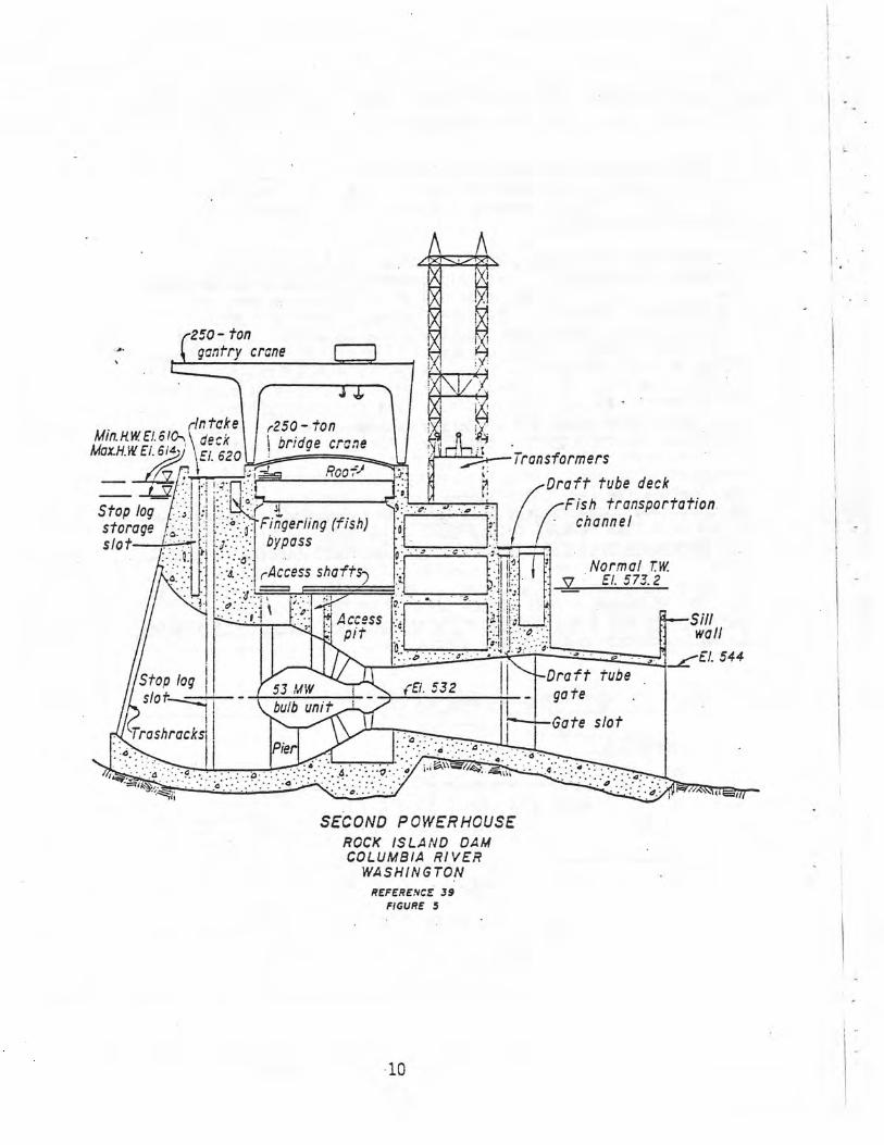
250- ton
I I. (gantry crone
rintake x250-ton M1n.KW. E1.6!0, ` deck bridge crane MazH.W El. bid ~EL 620
Roo -1 ...tom :-. I ,.~ •-:~-::.
Stop log storage Fingerling (fish) slot—L- r; :~:=.:.. bypass
Access shafts)
~. Access pit l
r-tea---Transformers
:r Draft tube deck
Fish transportation. o channel
Normal T. w. q El. 573.2
Sill wall
-El. 544
Stop log ; Ora f t tube I . 53 WW i ~El. 32 ate s!o t~~
bulb unit ' ! g
Gate slot `Troshracksi~ :a
Pie
r. ,- .a.,...• Q. .Q,. •e - • .
.a• _.•:-..;-,9-,,.•e j.iG~» . //.a,..~ltii' 4' '" to•
SECOND POWERHOUSE ROCK ISLAND DAM COLUMBIA RIVER
WASHINGTON
REFERENCE 39 FIGURE S
10

IV. STATUS OF STANDARDIZATION
A. Standard "Off the Shelf" Units
A few package-type turbine and generator units are available in the low-head range (less than 20 m). These predesigned units reduce equipment costs by eliminating the need for site-specific engineering and by using standardized manufacturing techniques. However, the standard flow passage shapes may result in a loss in turbine efficiency. These units have either fixed runner blades or fixed wicket gate positions or both, resulting in less operational flexibility. The economics of each potential site should be evaluated to determine if th*e savings obtained with "off the shelf" units outweigh the losses. The following standardized units are presently available:
1. Tube Turbines
Allis-Chalmers tube turbine units. - Ten standardized packaged designs are available. Single units have capacities to 5000 kw at heads up to 15 m. Flow is controlled with a butterfly valve in the intake. The wicket gates are fixed and the runners are either fixed or adjustable. Figure 6 shows the arrangement of the standard, tube units.
Karlstads Mekaniska Werkstad (KMW) miniturbines. - These units are available for horizontal or vertical installaticn for flows from 1 to 15 m3/s and heads from 4 to 25 m. Outputs range from 100 to 1800 kW. Figure 7 is a typical arrangement. The turbines have fixed guide vanes and fixed runner blades, although the position of the latter can be changed when the turbine is stationary. Flow is controlled with a butterfly valve.
2. Bulb Turbines
Fuji package-type bulb turbine and generator. - Available in 19 models covering a range of net heads from 5 to 18 m and outputs from 300 to.4000 kW. The runner is of the fixed blade type and the flow is controlled with movable wicket gates. A sectional drawing of the standard bulb turbine and generator is shown on figure 8.
11

Pumping Adjustable ontrol and unit blade control excitation
cubicles z
erminal
j box i
Ground Generator Runner 0 resistor Draft tubg
width '0
£ 1 F G H Speed
i Removable top increaser
' portion of I Disconnect draft tub coupling
PCckingi ~ ~r~Generator
-01CL ~ Intake End of steel inlet valve draft tube valve liner
A-Runner di .
BASIC DIMENSIONS A= Runner diameter in millimeters (inches) = I.00
All other dimensions are in proportion from runner diameter
A 750 1000 1250 1500 1750 2000 2250 2500 2750 3000 (29.5) (39A (49.2) (59.6) (68.9) (78.7) (88.6) :98.4) (108.3) (118.1)
B 1.43 L37 ;.34 1.32 1.31 1.30 1.29 1.28 1.27 1.22 C 9.28 8.66 8.28 7.80 750 7.34 7.19 7.08 7.03 6.97 D 2.00 2.00 2.00 2.00 2.00 2.00 2.00 2.00 2.00 2.00 E 0.73 0.70 0.70 0.70 0.66 0.65 0.64 0.64 0.64 0.63 F 1.75 1.60 1.52 1.50 1.46 1.45 1.42 1.40 1.38 1.47 G 3.07 3.04 3.02 2.93 2.88 2.87 2.86 2.85 2.92 2.87 H 1.33 1.32 1.32 1.13 1.13 1.12 1.22 1.13 1.10 1.07 J 0.93 0.93 0.93 0.93 0.93 0.93 0.93 0.93 0.93 0.93 K 1.49 1.49 1.49 1.49 1.49 1.49 1.49 1.49 1.49 1.49 L 0.93 0.90 0.83 0.37 0.80 0.78 0.77 0.77 0.76 0.73 M 1.33 1.30 1.28 1.25 1.26 1.22 1.22 1.22 1.22 1.17 N 3.00 2.75 2.60 2.50 2.43 2.38 2.33 2.30 2.27 2.25
ALLIS-CHALMERS STANDARD TUBE UNITS FIGURE 6
12

KMW STANDARD MIN1 TURBINES FIGURE 7
13

L RUNNER Z DISCHARGE RING 3. BULB FOR TJP6;;NE 4. WICKET GATE 5. STATOR 6. ROT GR 7. PENSTCCK 8. DRAFT TUBE 9. BULB FCR GE-VERA70R 10. UPPER STAY V ;:E ll. LCVVER STAY VANE
I
FUJI PACKAGE TYPE BULB TURBINE AND GENERATOR
FIGURE 8
14

3. Cross Flow Turbines
Ossberger "cross flow" turbine assemblies are available in a range of units which have the ability to cope with variations in head and discharge on small dams. The crossflow turbine is a radial impulse-type turbine. The water is forced through a guide vane system and the blades of the cylinc rical runners. The water then passes through the runners again to the outlet. Figure 9 is a cross section through a crossflow turbine. The adjustable guide vane allows Power generation from 16 to 100 percent of design flow. Although the efficiency for this unit is not as high as for axial flow turbines, it may have widespread application to small sites where limited storage is available and flow and head vary widely.
HORIZONTAL ADMISSION VERTICAL ADMISSION
OSSBERGER CROSS-FLOW TURBINE FIGURE 9
15
4. Small High-head Turbines
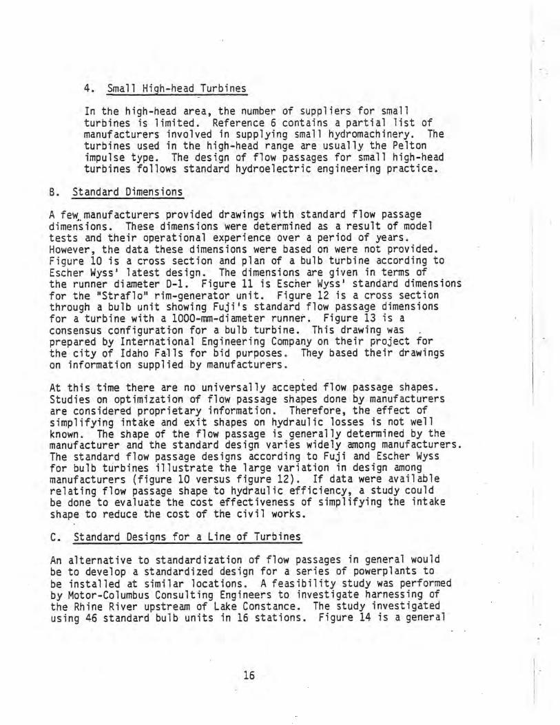
In the high-head area, the number of suppliers for small turbines is limited. Reference 6 contains a partial list of manufacturers involved in supplying small hydromachinery. The turbines used in the high-head range are usually the Pelton impulse type. The design of flow passages for small high-head turbines follows standard hydroelectric engineering practice.
B. Standard Dimensions
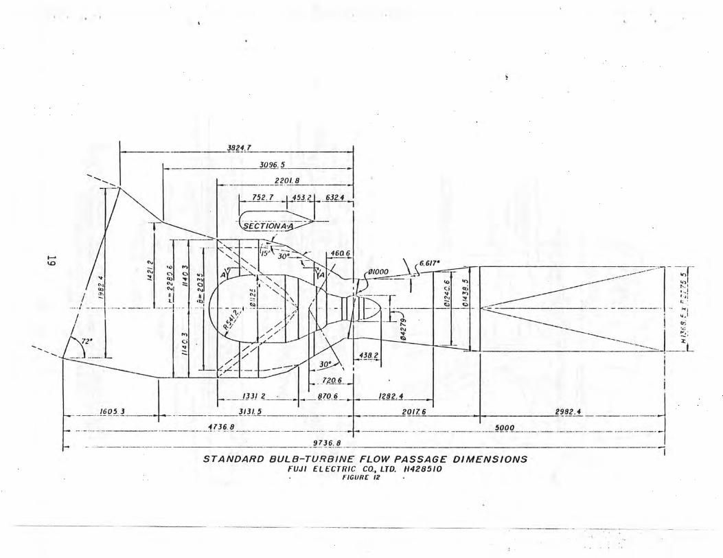
A few manufacturers provided drawings with standard flow passage dimensions. These dimensions were determined as a result of model tests and their operational experience over a period of years. However, the data these dimensions were based on were not provided. Figure 10 is a cross section and plan of a bulb turbine according to Escher Wyss' latest design. The dimensions are given in terms of the runner diameter D-1. Figure 11 is Escher Wyss' standard dimensions for the "Straflo" rim-generator unit. Figure 12 is a cross section through a bulb unit showing Fuji's standard flow passage dimensions for a turbine with a 1000-mm-diameter runner. Figure 13 is a consensus configuration for a bulb turbine. This drawing was prepared by International Engineering Company on their project for the city of Idaho Falls for bid purposes. They based their drawings on information supplied by manufacturers.
At this time there are no universally accepted flow passage shapes. Studies on optimization of flow passage shapes done by manufacturers are considered proprietary information. Therefore, the effect of simplifying intake and exit shapes on hydraulic losses is not well known. The shape of the flow passage is generally determined by the manufacturer and the standard design varies widely among manufacturers. The standard flow passage designs according to Fuji and Escher Wyss for bulb turbines illustrate the large variation in design among manufacturers (figure 10 versus figure 12). If data were available relating flow passage shape to hydraulic efficiency, a study could be done to evaluate the cost effectiveness of simplifying the intake shape to reduce the cost of the civil works.
C. Standard Designs for a Line of Turbines
An alternative to standardization of flow passages in general would be to develop a standardized design for a series of powerplants to be installed at similar locations. A feasibility study was performed by Motor-Columbus Consulting Engineers to investigate harnessing of the Rhine River upstream of Lake Constance. The study investigated using 46 standard bulb units in 16 stations. Figure 14 is a general
16

O. l ~~~~•~~• : s Ilo; 8utb-7urbine
AY, ~•: J.
YA
Y 8
o O , C1
.
• p er ~Q 9. o '~O
2 34 4,4 _ I
m m
2 O
U W
STANDARD BULB TURBINE FLOW PASSAGE DIMENSIONS ESCHER WYSS
FIGURE /0
17

crr
TW
IA)
o_
a
r.
1
_-_ 3824.7 ----
3096.5
2201.8
752. 7 453.2 632.4 ,
SECTIONA~—
~15'3Ua _ - 460 6
V ~' ~ V n A j \ ~A X1000 - a e
W N! ` NI a~ ~~ ~(/T-
Ci Qi " :r 11 .. µ M
72' -
_. / 438.2 30*
720.6
_.-_1331 2 _ -,• _870,6- 1282.E
-----1605.3_-_ _ --_31315 ---- -_ _ _ 2017. 6 2982.4 -
_ _ ----- -- ---_ ---- 4736,8 --------_____ - -- - .....-- -----_ 5000__._..___._-_ ------------
- - ----- - - --- - ---9736. 8 .-- - -- STANDARD BULB-TURBINE FLOW PASSAGE DIMENSIONS
FUJI ELECTRIC CO., LTD. H428510 FIGURE 12

~r -- ~YB CONCRETE OUTLINE
r POWERHOUSE ' AND APPURTENANCES
I r I r
TRANSFORMER
007LINC OF EXCAVATION
AREA ALLOCATED FOR FUTURE FISH PASSAGE
GENERAL PLAN
cf RUNNER 61r 72_ _~
STOPLOG TRANS- NORMAL T.W. EL 4714 FORMER (Oa :,OGO CFS)
?-MAX. T.W. 4728 rc inn it ~~ Et 14 4 C 47'T M114.T.W. E7.4711
F , a (02 2,000 CFS)
1 `~ ~ r __ •!' ,1 ~ —
{ =-_fL 4690.3 ~~ I fZom79 ' ~£ Ef. 4701
~.Amt.,
SECTION A-A
NON-OVERFLOW 25br , EARTH=ILL OWE i SPILLWAY 112r !PEL1,_-"NGA-,E•POWEPFOL5E! SPILLWAY 66'
721 POFGATE i 4G'ru' ~° 3B' e ` SPILLWAY T'D T II-TOPOFDECKT CREST EL K73a.E'• t T 3~ El. 4740 ! i
n•_..~.n .•o. _ y a . ~f~=i....i ~j
-`+mot-:~: ti:- `..i rl
ASSUMED TOP OF ROC X / :: o • _i i EL 472? _ ~̀—~ E1.4701
PELICAN GATE
SECTION B-B .,.•.,~
CONSENSUS CONFIGURATION FOR IDAHO FALLS HYDROELECTRIC PROJECT UPPER POWER PLANT
INTERNATIONAL ENGINEERING COMPANY FIGURE 13
20
NORMAL WS. EL 4734 Cl. 4740.5l MAX. W. S. EL 4 73 9,-)
ASSUMED TOP_ I(+ OF ROCX~ R45NRAC
-OUTLINE OF PIERS
SUL.-... N

A
Injector Reservoir shaft.
e!e V.7 f. on
Trash rake and stop log crane
-z —Trash channel -20-Ton crone
I Mochine hall
Downstream stoplogs
Max foil ;/ rvotef v v U t I o n
Min toil water Troshrach J:J
-.Generator I re
Dro f t tube
_JJ
POWERPLANTS ON THE RHINE RIVER FROM DOMAT (EMS) TO FLXSCH MOTOR COLUMBUS CONSULTING ENGINEERS
FIGURE 14
layout developed for the project. This concept may be applicable to development of low-head power on American rivers with several possible low-head sites, such as the Ohio or Mississippi Rivers where numerous navigation dams without power generation currently exist. A standard design would reduce the costs associated with site-specific engineering for each powerplant.
D. Mini Power stations in Sweden
The Swedish Power Association has initiated a program to overhaul and replace discontinued small power stations (100-1500 kW) in Sweden (reference 7) .
The program includes hundreds of stations having a total. output of 1 TWh annually which corresponds with a total installed capacity of about 235 MW. A few simplified automated axial flow units were developed for the program. The present electric power production in Sweden is about 85 TWh of which about 60 TWh is hydropower production. Sweden installed six pilot plants during the 1975-77 period to study operation and economics of the units selected. Figure 15 shows the various-types of mini powerplants used. The design of the flow passages depends on the type of unit used.
In most of the small installations in Sweden it is possible to run the power stations intermittently. This makes it possible to design the turbine with fixed runner blades and fixed guide vanes and leave out the regulator. The turbines are run as the reservoir is drained and shut off as the reservoir fills up again. The turbine efficiency is 90-92 percent.
At heads less than about 6 m type B or C is used (figure 15). At heads over 6 m type A is used. The vertical-shaft type is used so the turbine can be positioned below the water level to reduce the potential for cavitation.
If the installations cannot be run intermittently they can be run with regulation for constant water level upstream using units with movable runner blades. Turbine efficiency is 85-91 percent.
The pilot stations indicated that it was difficult to bring the costs down enough to make the units economically profitable. However, the Swedish Government has made economic aid available (up to 35 percent of the cost) for the least profitable projects. Economic aid was considered to be justified since hydropower reduces dependence on imported oil and is a renewable, environmentally acceptable form of energy that would otherwise be wasted.
22

w
VARIOUS TYPES OF MINI-POWER STATIONS SWtDISN POWLR ASSOCIATION (REFERENCE 7)
FIGURE 15

E. Comments on Standardization
Most designers and consultants contacted felt that standardization of the inlet and outlet sections for low-head hydropower installations will not always bring the optimum solution. The shape of the water passage is influenced by the structural support system requirements and the geology of the site. Even units designed by the same manufacturer vary from project to project. However, the need for a manual to serve as a guide and promote standardization of flow passage designs was considered to be a worthwhile objective. While not all designs would be exactly the same, a manual would bring together information contained in scattered sources and aid in the planning and design process.
24
V. CURRENT DESIGN PRACTICES
This section summarizes material in technical literature, and comments made by manufacturers and designers concerning flow passage design. Main points covered in the references are discussed; however, the references should be referred to if more detail is required. The hydraulic design of the draft tube is customarily done by the manufacturer, since it is considered an integral part of the turbine in determining turbine performance. The hydraulic design of the other flow passages is normally considered a part of the overall plant design. However, the manufacturers of standard designs usually control the design of the other flow passages also.
A. Forebay
The design of the entrance channel in the forebay should provide a uniform flow distribution to avoid the tendency for vortices and to minimize trashrack losses. The entrance channel is designed according to common engineering practice. If the geometry of the approach channel is in question, a model study can be done to assure acceptable flow conditions. Flow velocities and surges are of particular con-cern on navigable rivers. Run-of-river low-head dams are typically designed with the powerhouse on one side of the river and an overflow weir-type dam on the other side. In some cases an entrance channel to the powerhouse is excavated in the bank. If a navigation lock is included in the dam it is usually on the opposite bank from the powerhouse. Another possible configuration in a narrow dam is to have a gated weir over axial flow turbines.
B. Intake
1. - Vortex formation. - Intakes should be designed with a sufficient submergence to avoid vorticies. Air-entraining vortices may decrease turbine efficiency and pull floating debris into the turbine. Reference 8 describes the development of design criteria to avoid vortices at low-head intakes, based on a study of 29 existing hydroelectric intakes.
The intakes studied have the general configuration shown in figure 16. The factors which appear to affect the formation of a vortex are: geometry of the approach flow, velocity at the intake, the size of the intake, and submergence. This article concentrates on the effects of velocity, intake size, and submergence on vortex formation. The following relationship was developed by trial and error:
S = CVd1/2
25

GENERAL CONFIGURATION OF AN INTAKE REFERENCE 8
FIGURE 16
25
F-z 20
Is U leis
W /o Z QS
5
OW 0 IO 20 30 40 50 60
V (d ) '/2
LEGEND: a Intakes with vortex problems c Intakes with no vortices
' Recommended min. submergence
RECOMMENDED MINIMUM SUBMERGENCE REFERENCE 8
FIGURE 17
26

The effects of lateral approach flow were not evaluated in this study. However, Montreal Engineering Company of Canada uses a coefficient C of 0.3 for intakes with symmetrical flow and 0.4 for lateral approach flow to determine minimum allowable submergence. These coefficients correspond to the lower and upper limits, respectively, of the shaded area on figure 17.
If the available submergence is not adequate, a model study can be done to study vortex formation. However, accurate prediction of vortex formation using a scale mcdel is difficult. The effect of surface tension and air entrainment are important and are difficult to study in a Froude scale model. Reference 9 describes
'a general method for investigating potential scale effects on free surface vortices, so that a projection to prototype operating conditions can be made. According to reference 9 "projection of model vortex severity to the prototype implies that tree Reynolds number must be increased without changing the Froude number, and that the trend of a parameter related to vortex severity be documented." The curves of vortex severity in figure 18 were generated by observing vortex severity in a model by varying water temperature (T), thus varying the viscosity and Reynolds number. , Froude ratios were also varied by increasing or decreasing model discharge. The Reynolds.number can be increased in the model by changing the water viscosity or changing the model scale ratios. The easiest method is to operate the model at different water temperatures to change the viscosity. The prototype vortex severity is predicted by noting the vortex severity at the prototype Reynolds number for a Froude number ratio of 1. The vortex severity trends must be extrapolated to the prototype Reynolds number in many cases.
W /LOCI r VORTEX SEVEF NO
Tj I\~12 T3 7, I I
if ~i
f 16
J Rm Rp
Rr vD
VORTEX SEVERITY VERSUS FROUDE AND REYNOLDS NUMBERS
REFERENCE 9 FIGURE IS
27

Reference 10 investigated the use of rafts placed under the water surface and other devices to prevent formation of air entraining vortices at Grand Coulee Third Powerplant. The hydraulic model study included vortex tests on the effect of trashrack structures, upstream channel geometry, intake modifications, and submerged and floating rafts. The report concluded that the prediction of prototype vortices using a model is suspect. The value of the results of this report and the vortex suppression techniques described would be enhanced by prototype observations.
Reference 11 reports on the use of the flow "injector wall." This ' device has the same effect as a raft. Because of an increase of surface current, the vortices are suppressed. The injector was developed for bulb turbines on run-of-river plants to increase flow velocity on the surface to promote movement of floating debris toward the trashrack on the front of the powerhouse. A flow injector is shown on figure 14. The bibliography in reference 9 contains additional references which may be helpful in determining minimum submergence.
2. Pier design. - In typical run-of-river plants a flow separating pier divides the powerhouse and spillway. Piers also divide the intakes where there are multiple units. The size and shape of the pier should be carefully designed to avoid stagnant areas or flow disturbances which may cause excessive head losses or eddies. Hydraulic Design Criteria (HOC) by the U.S. Army Corps of Engineers (reference 12) contains design information useful in designing piers and intakes.
Reference 51 has information on German practice in designing the size and shape of flow separating piers between a powerhouse and weir. The pier design procedure takes into account the location of the powerplant with respect to bends in the river, alinement with the weir, and the entrance channel to the powerplant cutting into the riverbank. Figure 19a shows the general shape of the flow separating pier. The following are the limits on the length and width of the pier:
0.85 B < L < 0.95 B 0.28 B < B1 < 0.35 0.72 B > B2 > 0.65
The following formula defines the width of the pier (B).
B = CQ2/5
The coefficient C varies between 0.7 and 1.4 depending on the factors mentioned above. Reference 51 should be referred to for det ails of this design method.
r:

0.267 F
TYPE I
b z N O N O
:REST AXI.
_r L TYPE 2
133 Hd RAD
267 Hd
B.
~\ ~Re ti
\ f
I RA \\ A
Bt Bt I TRASHRACK BASE
FLOW SEPAR,47! J G PIER BETWEEN POWERHOUSE AND WEIR
REFERENCE 51 FIGURE /90
0.267 Hd (0.20 Hd) RAD -cz=--
0.267 Hd (0.20 Hd)
O
~ j
1 N O l'
O
CREST AX1S 0.267 Hd 1-7
TYPES 3 AND 3A TYPE 4
Ha= CESIGN HEAD
PIER NOSE SHAPES TYPE 3A DIMENSIONS IN PARENTHESES
REFERENCE /2 FIGURE /9b
29

HDC sheets 111-5, 111-6, and 122-2 describe pier effects for gated overflow spillways. Abutment effects are described in sheets 111-3/1 and 111-3/2. When spil-lways are operated with adjacent bays closed the piers adjacent to the closed bays produce abutment-type effects. Although these pier design criteria are for spillways and not for submerged intakes they do show the relationship between pier shape and flow contractions. Figure 19 shows the five different pier nose shapes investigated. Pier types 1 and 4 (see figure 19b) are the least desirable from the standpoint of negative pressures. Types 2, 3, and 3A were recommended for general use with high heads. Type 3A had the most desirable flow contraction characteristics.
The design of the flow separating pier .could benefit from further research. If the contraction could be reduced without using a wide separating pier the flow capacity may be increased considerably.
3. Trashrack design. - Trashracks are typically used to prevent large debris from entering the turbine. Reference 13 contains information on head losses through rectangular bar trashracks. This article evaluates previous work on trashrack and baffle losses and introduces additional data to supplement design information. Equations are developed to calculate the head loss as a function of the approach velocity and clear spacing between the rectangular bars. The head loss through the trashrack was found to be a minimum for bars with depth over thickness (d/t) ratios of about 3.0 for any solidarity (S) between 0.25 and 0.75. Where solidarity is the ratio of the flow area blocked to the total flow area. If the trashrack blocks one-half of the flow area the solidarity would be 0.50:
The following equations were found to accurately predict total trashrack and baffle head loss.
hI (d/t < 3.0) = 2g (mK
1 V2 ( ) - 1\2
h (d/t > 3.0) = g p
2 + (1 - k)2~ K m
in which m = the coefficient of contraction, and K = b/(t + b), where b = the clear spacing between bars, t = the thickness of the
bars, and 2g = the approach velocity head.
Harza Engineering Company suggests velocity through the gross area of the trashracks should be limited to 1.5 m/s at rated turbine discharge. A large spacing of rack bars (150 mm) can be used for axial flow turbines. The relatively high approach velocity does not produce excessive trashrack head losses if the approach flow is not oblique.
30

4. Intake shape. - Intake shapes vary with the type of turbine used. Intakes are either circular or have a rectangular to circular transition. The face of the intake is either vertical or inclined. However, vertical intake faces simplify design and construction including slots for intake gates, bulkheads, and trashracks.
The hydraulic design of the intake is basec largely on engineering judgment; the classical bellmouth criteria are used as a starting point. The ent-ance end of the bellmouth curve is then truncated to obtain a short intake profile which achieves required contraction in a length equal to approximately I runner diameter. General information on the effect of intake shape on hydraulic losses is not available. References 1 and 46 indicate, however, that the size of the intake could possibly be reduced without introducing excessive additional hydraulic losses. The ideal bellmouth entrance design was developed for high-velocity conduits. The velocity for low-head turbines is much lower. It is possible that savings could be achieved in trashracks, bulkheads, entrance gates, and other areas by reducing the entrance size.
It might also be possible to simplify the framework by using flat surfaces to approximate curved surfaces. The cost effectiveness and practicality of these changes require further study to determine if reducing entrance sizes and simplifying intake shapes are worth pursuing.
5. Fish passage allowances. - If passage of fish is a factor, the maximum allowable intake veloci.ty or other intake design parameters may be controlled by the design of fish passage facilities.
C. Runner Diameter and Turbine Setting
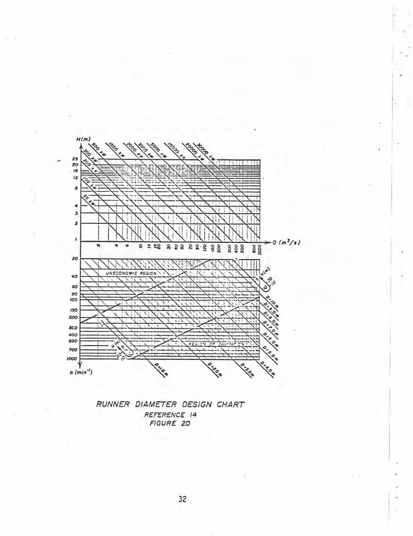
The turbine setting is determined by the allowable specific speed. The specific speed is usually controlled by the cavitation potential. From an economic standpoint, it is desirable to select the highest specific speed possible since this results in a smaller, lighter generator. The cavitation Potential of an axial flow .urbine is generally lower than a Kaplan unit. This allows the axial turbine to have a higher setting or a higher speed (reference 2). .''her factors such as smooth operating range and submergence also enter into the design. Reference 14 used data from 130 power to develop a design aid to determine -:Inner diameter and t-ie powerhouse size. A design chart was developer to determine the approximate diameter of a tubular 'axial flow) unit. The upper diagram in fig-ure 20 makes it possible to determine the capacity in ~;lowat.;. In the lower diagram the runner diameter can be determines. The head H is marked on the lateral scales and a line is drawn connecting these
31
d
4
H(M)
40
60 do f00
/So 200
WO 400 Soo
700
1COO
s.. ~ s !e•
f~i I i i
N,,,,;' ~ ~ ~I IX"i N ~ N ~ o O ~ m0 n, !$ A w•Q u S S O O S O
YET^
O ~ O i
l~1 ~o \o
O O~ ip S ~
O9 ~
p 'O
o a 0
p- a
I~ O
RUNNER DIAMETER DESIGN CHART REFERENCE 14
FIGURE 20
32

points. The runner diameter can then be determined for a specific discharge (Q) or specif-ic speed (n). The range of applicability is bounded by a region of uneconomic operation and the region of cavitation. The assumptions are checked by comparing existing projects with predictions using this method.
Reference 15 also gives charts for finding the approximate runner diameter and rules of thumb enabling the approximate dimensions for an entire unit to be found. Figure 21 is an empirical plot of the relation between diameter (D) and the ratio of power to head (Hp/H). The formula is
D = '0.24 Hp 0.4 H
in metric units. For power in terms of kW of turbine output the formula .is
D = 0.272 KW )0.4 H
This reference also contains an extensive bibliography on axial flow turbines.
Reference 16 presents a method for developing a nomograph for determining the setting of a hydraulic turbine relative to the taiiwater level. The turbine manufacturer must supply data con-cerning cavitation performance to.develop the nomograph. This method is useful only for the installation under consideration.
D. Draft Tube
The hydraulic oesign of the draft tube is customarily determined by the turbine manufacturer, since it is considered an integral part of the turbine in determining the turbine performance. However, there is potential for decreasing the length of draft tubes, thus decreasing the cost of the civil works. According to reference 17, the most efficient conical draft tube would be about 10 runner diameters long with a total included angle divergence of about 7% Economics usually limits the length of the draft tube to 4.5 to 5 runner diameters with the total angle of diversion of about 13 to 15% A study done on the feasibility of low-head hydroelectric generation in 1969 (reference 18) concluded that, "The section of the civil works structure where improvement would be most significant is the draft tube." The draft tube accounts for about 30 percent of the cost of the civil works in a low-head structure. There are several possible methods presented in reference 18 for preventing boundary layer separation, thus shortening the draft tube (figure 22).
33

• 94
34
1000
800
CL _ = 600
2000
400
200
too 2 4 6 8
+ D
TUBULAR TURBINES ( DIAMETER vs HP 1
REFERENCE 15
FIGURE 21
72 ° • a2
69 26
74
D .24 HP 0.4
=(y 1 • 48
!9• • 57
21 56
76 • i
l6• 49
8l • 58
• 8
go/ 0 '1:60 75
l5 68
• HP = TURBINE OUTPUT IN 92 • 32
METRIC HP (735 23 WATTS
73 • H = RATED HEAD IN METE. ,
129 D= RUNNER DIAMETER IN METERS
91•

FLOW
SHORT DIFFUSER WITH CONTROL
VANES
FLOW
SHORT DIFFUSER WITH SCUNDA.RY
LAYER SUCTION
FLOW
77t
MULTIPLE CONE CIFFUSER
POSSIBLE METHODS FOR -SHORTENING DRAFT TUBES REFERENCE IS
FIGURE 22
35

The study concluded that a need existed for research in the design of draft tubes to apply modern principles of boundary layer control to reduce the length of draft tube diffusers. Research in this area has not been done on hydraulic turbines. The concept of boundary layer control has been bypassed in favor of simple conical diffuser designs because of the potential risks of complications involved with a new concept. Shortening of the draft tube in this manner would probably require a successful demonstration project before it would be accepted. Reference 19 reports on research to shorten diffusers for wind turbines using boundary layer control. This research indicates that there is a promise of reducing the length of diffusers by an--order of magnitude while maintaining efficiency.
Reference 20 deals with the question of whether addition of swirl to fluid, otherwise flowing axially, in a diffuser would improve. its performance. Model studies indicated that the coefficient of performance of conical diffusers is improved by an addition of a swirl velocity component corresponding to a forced vortex. This paper concluded that the optimum swirl angle is about equal to the diffusers total conical angle. Improvements are not likely to extend to diffusers with total conical angles greater than 30% Reference 21 provides a more detailed account of the research.
Reference 22 reports on'a model study done to permit selection of dimensions for diffuser channels of hydraulic machines. This study states that performance of the diffusers with large flare angles would be improved by adding a strong twist to the flow. However, this leads to an increase in other types of losses in the hydraulic machine. This article recommends a total draft tube expansion angle of 15-17' for horizontal encapsulated (bulb) units. This recommenda-tion resulted from a number of theoretical and experimental studies in the U.S.S.R.
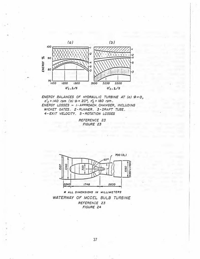
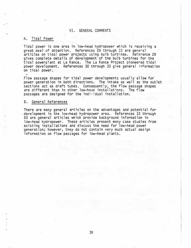
Reference 23 reports on a study that investigated the interaction and losses as flow moves through the various elements of the flow passage in a bulb turbine. Flow parameters were measured in various turbine operating modes, characterized by blade angles, 0 = 0, 5, and 20' and rotating speeds N = 110, 140, and 180 r/min with various settings of the wicket gates. Based on these data, energy losses in individual sections of the flow passage are presented- in a chart for several operating modes. Figure 23 gives energy balances for two turbine operating modes. It should be noted that the selection of design data should be based on minimum total losses in the turbine as opposed to minimum losses in each section of the waterway. The results from this study can be used to estimate energy losses in the elements of flow passages in actual turbines
36
(b)
to cc W W 80
[Iei 1100 1200 1.300 3100 .3,200 3.300
0z ,.1/S 011,1/s
ENERGY BALANCES OF HYDRAULIC TURBINE AT (c) 0=0, n I = 140 rpm (b) P = 20° nZ = 180 rpm.
ENERGY LOSSES — I - APPROACH. CHA,,VBER, INCLUDING WICKET GATES. 2 - RUNNER. 3 - DRAFT TUBE. 4-EXIT VELOCITY. 5-ROTATION LOSSES
REFERENCE 23 FIGURE 23
r 700 (D,)
65 ° 1 I
N -TO
Q O C
O
L.1401 1748 2830
t1f ALL OIMENSIONS 1N M1LL/ME7ERS
WATERWAY OF MOC EL BULB TURBINE REFERENCE 23
FIGURE 24
37

if the flow passage shapes are similar to those used in this study. Figure 24 shows the dimensions of the model.
The literature contains numerous articles relating to diffuser design. The biliography in reference 17 contains 39 references (mostly for airflow diffusers) which may be helpful in designing draft tube diffusers. However, most of these studies are for uniform flow conditions. In a hydraulic turbine the runner speed, amount of swirl in the flow and other factors influence the diffuser efficiency. References 24 through 28 provide additional information on draft tube design. Reference 52 contains developments in design and c ostruction of draft tubes in the Soviet Union and Western Countries. This reference contains general information on draft tubes of hydraulic turbines as well as theoretical principles of draft tube design.
The designer is not always free to select the optimum flow passage dimensions. Other considerations such as structural requirements or fish passage facilities may affect the shape. For example, allowances for fish passage facilities may make it necessary to change the flow passage geometry.
Gates should not be located immediately downstream of the runner in the draft tube. The design of this section is critical to the efficiency of the draft tube. The draft tube gates at Rock Island Dam are located about 2 runner diameters downstream.
F. Tailrace
The outlet from the draft tube is designed to have a minimum submer-gence of 0.75 to 1.0 m at low tailwater. The flow discharging from the draft tube at low tailwater may cause surges and turbulence and the rise of the channel bottom may cause fluctuations in the tailwater level. The channel and the tailrace should be designed to minimize these problems. According to a well-known turbine manufacturer, the relationship between the rise in the channel bottom and the tailwater is not known. At this time, consultants recommend that a steep rise in the channel bottom be avoided; however, the allowable rate of rise 'is not defined.
VI. GENERAL COMMENTS
A. Tidal Power
Tidal power is one area in low-head hydropower which is receiving a great deal of attention. References 29 through 33 are general articles on tidal power projects using bulb turbines. Reference 29 gives complete details of development of the bulb turbines for the tidal powerplant at La Rance. The La Rance Project pioneered tidal power development. References 30 through 33 give general information on tidal power.
Flow passage shapes for tidal power developments usually allow for power generation in-both directions. The intake as well as the outlet sections act as draft tubes. Consequently, the flow passage shapes are different than in other low-head installations. The flow passages are designed for the ind-ividual installation.
B. General References
There are many general articles on the advantages and potential-for development in the low-head hydropower area. References 33 through 50 are general articles which provide background information in low-head hydropower. These articles present many case studies from existing installations and discuss the need for low-head power generation; however, they do not contain very much actual design information on flow passages for low-head plants.
39

BIBLIOGRAPHY
[1] Peterka, A. J., and Lindholm, E. A., "A New Look at Penstock Entrance Designs," Bureau of Reclamation, paper presented at the Western Water and Power Symposium, Los Angeles, California, April 8-9, 1968
[2] "Low Head Power Generation with Bulb Turbines, "International Engineering Company, Inc.
[3] "The Straight-Flow Turbine Turns Full Circle," Water Power and Dam Construction, January 1977, pp. 31-35
[4] Miller, H., "The STRAFLO Turbine the Realisation of Harza's Idea," Escher Wyss News, pp. 3-46 i.
[5] Eberhardt, A., "The Modernization of a Small Hydro Plant," Civil Engineering-ASCE, September 1977, pp. 60-61
[6] Lutz, J. J., "Small Hydro-Electric Units - Where to Find Them," Civil Engineering-ASCE, September 1977, pp. 87
[7] Persson, Thorild, and Lasu, Sten, "Mini Powerstations in Sweden," Swedish Power Association, September 1, 1978
[8] Gordon, J. L., "Vortices at Intakes," Water Power, April 1970, pp. 137-138
[9] Durgin, W. W., and Hecker, G. E., "The Modeling of Vortices at Intake Structures," Proceedings, Joint Symposium on Design and Operation of Fluid Machiner , Colorado State University, nternationa Association or Hydraulic Research, American Society of Mechanical Engineers, American Society of Civil Engineers, Vol. 1, June 1978, pp. 381-391
[10] Zeigler, E. R., "Hydraulic Model Vortex Study, Grand Coulee Third Powerplant," United States Department of the Interior, Bureau of Reclamation; February 1976, REC-ERC-76-2
i [11] Bisaz, E., Taubmann, K. C., and Fischer, P., "Improvement in
Transport of Floating Debris," Water Power and Dam Construction, November 1976, pp. -45
i
[12] U.S. Army Corps of Engineers, Hydraulic Design Criteria, prepared for Office, Chief of Engineers, by U.S. Army Engineer Waterways Experiment Station, Sheets 111-5, 111-6, 122-2, 111-3/1, 111-3/2, and 221-1
40

[13] Osborn, J. F., "Rectangular-Bar Trashrack and Baffle Headlosses, Journal of the -POWER DIVISION, Proceedings of the American Society of Civil Engineers, November 1968, PO 2, pp. 111-123
[14] Heinemann, E., Kraft, K. D., and Rouve, G., "Runner Diameter of Tubular Turbines," Journal of the POWER DIVIS :N, Proceedings of the American Society of CivilEngineers, anuary 1976, PO 1, pp. 53-61
[15] Sutherland, R. A., "Tubular Turbines," Washington State University College of Engineering Research Division, Technical Extension Service, Bulletin 309, 1968
[16] Dadu, V., and Bedros, N., "Determination of Low Head Turbine Installation Quota as Compared to the Downstream Level," Translated from the Rumanian: Energetica (Rumania), Vol. 25, No. 2, pp. 45-48, February 1977, Bureau of Reclamation, May 1978
[17] Kline, S. J., Abbott, D. E., and Fox, R. W., "Optimum Design of Straight-Walled Diffusers," Journal of Basic Enaineerina, ASME, September 1959, pp. 321-331
[18] Mercer, A. G., "Study of Factors Affecting Feasibility of Low Head Hydroelectric Generation," Civil Engineering Department Colorado State University, prepared for United States Department of the Interior, Bureau of Reclamation, March 1969, No. 14-06-D-6586, CER68-69AGM26
[19] Oman, R. A., Foreman, K. M., and Gilbert, B. L., Investigation of Diffuser-Augmented Wind Turbines, Part II - Technical Report, Research Department, Grumman Aerospace Corporation, prepared for Wind Energy Conversion Branch, Division of Solar Energy, Report RE-534, January 1977
[20] Wirasinghe, N.E.A., "Effect of Swirl on Conical Diffuser Performance," Proceedings Joint Symposium on Design and Operation of F 7-d ac finer , o orado StFte University, International Association for Hydraulic Research, American Society of Mechanical Engineers, American Society of Civil Engineers, Vol. 1, June 1978, pp. 223-245
[21] Wirasinghe, N.E.A., "Swirling and Non-Swirling Flow in Conical Diffusers, Ph.D. Thes's 1975, The City University - London
[22] "Selection of Optimum Dimensions for Diffuser Channels of Hydraulic Machines," Translation from Russian, Eneraomashinostroenie, No. 5, 1976, pp. 11-13, Bureau of Rec amation, Marc 9/8
41

[23] Varlamov, A. A., Liukonen, IU. N., and Ponarskii, L. I., "Study of the Operating Process of an Enclosed Hydraulic Turbine," Translation from Russian, Energomashinostroenie, No. 7, 1977, pp. 1-3, Bureau of Reclamation, May 1978
[24] Isaev, I., M., "Influence of a Method of Air Admission on Pressure Surges in Draft Tube Models of Axial Hydro-Turbines," Translated from the Russian: Gidromashinostroenie, Trudy LPI, No. 215, Moscow and Leningrad, pp. 8-68, 1961, by King, D. L., No. 756, July 1968
[25] ,. Alestig, R., "Influence of Draft Tube Dimensions on Kaplan Turbine Efficiencies," Int. Assoc. Hydraul. Res. Symp.. Stockholm, Sweden, Trans. Part 1, 1970, 12 p, 11ig.
[26] de Siervo, F., and de Leva, F., "Modern Trends in Selecting and Designing Kaplan Turbines," Water Power and Dam Construction, January 1978, Part 11, pp. -58
[27] Mikhailov, I. E., Mityurev, E. L., Kazennov, V. V., Volshanik, V. V., and Bondarenko, B. V., "Effects of Slots and Apertures in Floors of the Diffusers of Draft Tubes on the Power Characteristics of Hydraulic Turbines with Adjustable Blades," In Russian, Gidrotekh Stroit, n 9, September 1973, pp. 10-13
[28] Worster, R. C., "The Efficiency of Diffusers and Some Test Results on the Effect of Wall Roughness," The British Hvdromechanics Research Association, No. R. R. 554, March
[29] Cabanius, J., "The Rance Project and its Contribution to Hydroelectric Technology," The Rance Tidal Power Scheme, September-October 1966, French, pp. 847-860
[30] Casacci, S., "Large Bulb Units for Tidal Powerplants," Water Power and Dam Construction, Part 1, June 1978, pp. 45-47
[31] Casacci, S., "Large Bulb Units for Tidal Powerplants," Water Power and Dam Construction, Part 2, July 1978, pp. 47-50
[32] Wayne, W. W., Jr., "Tidal Power Possibilities in the United States," paper presented at ASCE Spring Convention, Pittsburgh, Pennsylvania, April 1978
[33] Stekov, M. L., "Experimental Horizontal Bulb Turbines for Saratov Hydropowerplant," translated from Russian: Eneroomashinostroenie, No. 5, pp. 6-10, 1969, by King, D. L., Octooer 1969
42

L34] Faschallegg, E., "The Kaplan Bulb Turbines of the Danube Power Station Ottensheim-Wilhering," Escher Wyss News, Vol. 48, 1975, pp. 13-18
[35] Gemaehling, Cl., and Savey, P., "The Multi-purpose Development of the River Rhone Valley," Water Power, November 1972, pp. 403-410
[36] Broad, W. J., "Small Hycro: Sleeping Giant," Science News, Vol. 114, July 15, 1978, pp. 42-44
[37] Warnick, C. C., "Why Low-head Hydroelectric Power?," Idaho's Water, April 1978, Newsletter of the Idaho Water Resources Research Institute
[38] Cotillon, J., "Advantages of Bulb Units for Low-head Developments," Water Power and Dam Construction, January 1977, pp. 21-26
[39] Steward, W. A., and Wayne, W. W., Jr., "Rock Island to Use Bulb Turbines - A First in the U. S.," Journal of the POWER DIVISION ASCE, December 1974, PO 2, pp. 175-
[40] Nussli, W., "Flumenthal - A Swiss Station Equipped with Three 8MW Tubular Turbines," Water Power, December 1969, pp. 466-471
[41] Cotillon, J., "Bulb Units: from Rostin to Avignon The Upsurge of a Technique," La Houille Blanche, a French translation, No. 2/3, pp. 179-200
[42] Corso, R. A., "Small Scale Hydro Development Institutional and Legal Problems," Federal Energy Regulatory Commission, Low Head Hydroelectric Technology Seminar, University of Idaho, June 6-7, 1978
[43] Klotz, L. H., and Manasse, F. K., "Low-Head/Sma", Hydro-Electric Workshop," September 6-9, 1977, at the New England Center for Continuing Education, prepared for Division of Geothermal Energy, Washington, D.C.
[44] Lilienthal, D. E., "Small Hydro Development May Answer Near-term Power Needs," Engineering News-Record, June 2, 1977, pp. 8-9
[45] Kassler, H. S., "Power from the Streams," Solar Ace, July 1978, pp. 16-19
[46] Rhone, T. J., "Hydraulic Model Studies for the Penstocks for Grand Coulee Third Powerplant," Bureau of Reclamation Report No. REC-ERC-74-12, August 1974
43

[47] Lalive d' Epinay, A. G., "The First Generators in Switzerland Driven Direct by- Bulb Turbines, Brown Boveri Rev. 4-70, pp. 177-181
[48] VanVranken, W. P., "Tube Turbines to Modernize Hydro Plants, Allis-Chalmers Engineering Review, pp. 14-17
[49] Popescu, D., "The World Evolution to Equipping the Low Head Hydroelectric Power Stations with Bulb Units and the Perspectives in Romania," Translated from Romanian Ener etica, Vol. 22, August-September 1974, No. 8-9, pp. 309-317
I [50] Weber, G., Nussli, W., Jacobsen, S., and Bohun, V., "Uprating
Switzerland's Hydroplants," Water Power and Dam Construction, February 1978, pp. 39-44
[51] Rouve, Dr. Ing. Gerhard, "Ver krafthaustrennpfeiler stromungsverhaltnisse an gekrummten Wanden," 145 Arbeit Aus Dem Theodor -Rehbock-Flussbaulaboratorium. Professor Dr. Ing. E. h., Dr. Ing. H. Wittmann, Tech. Hochschule Karlsruhe, January 1958
[52] Gubin, M. F., "Draft Tubes of Hydroelectric Stations" Energrya Press, Moscow 1970 translated from Russian, Available from the U.S. Department of Commerce, National Technical Information Service, Springfield, Virginia 22151
44