standardization of test method for salt spreader: air flow...
TRANSCRIPT

1
Report 11 Reduction of Karman 22jan13
Standardization of test method for salt spreader: Air flow experiments Report 11: Methods to reduce large eddy turbulence behind a salt truck
by Jan S. Strøm, Consultant
Aarhus University, Engineering Centre Bygholm, Test and Development 2012.
Summary The purpose of this study was to identify methods to reduce the large eddy turbulence generated by the salt truck with salt hopper and thus to reduce the tendency to generate uneven, fish tailing salt distribution. The survey of methods for airflow control included aviation, racing and road transport. Methods were identified as streamlining components on the truck and the use of vortex generators, paneled underbody and rear diffuser; trailer tail and side trim panels. It is recommended that adaption of these methods to a salt spreading truck with equipment are evaluated. The Aerodynamic Truck is an interesting example of how this may be done.
Airflow and salt distribution The fish tailing salt distribution shown in figure 1 was observed on a test road after one passage of a salt spreader truck driving at 30 km/h. The salt was concentrated in a few narrow bands having areas with low visual coverage in between.
Figure 1. Examples of salt distribution patterns after passage of a salt spreader truck The distribution patterns indicate the presence of a von Kármán vortex street, i.e. a repeating pattern of swirling vortices caused by the unsteady separation of flow of air (Strøm, 2011 figure 17). Simulated flow around a rectangle show that the eddies are shed continuously from each side, forming rows of vortices in its wake. The alternation leads to an eddy in one row being opposite the point midway between two eddies in the other row, giving rise to the distinctive fish tailing patterns observed (Strøm, 2012 figure 3 and Takai, 2012 figure 4). Ultimately, the energy of the eddies are consumed by viscosity as they move further downstream, and the fish tailing pattern disappears, but at this point most of the salt may be settled unevenly on the road.
A salt spreading truck with hopper and spreader is geometrically much more complex than a two dimensional rectangle, but basic principles of how to reduce the magnitude of the fish tailing air patterns in the wake may give inspiration to possible solutions.

2
Report 11 Reduction of Karman 22jan13
Streamlining To the left in figure 2 is shown a simulated vortex street around a cylinder. It is seen that the vortices are developing immediately downstream of the cylinder and result in a high frequency vortex street. To the right is shown the same cylinder, now with a fin. It suppresses the vortex street by reducing the region in which the side eddies can interact, and thereby reduces the interaction and the frequency in the wake further downstream.
Figure 2. Simulated vortex street behind a cylindrical obstruction without and with a trailing fin. The effect of providing a streamlined fairing around the cylinder is shown in figure 3 in the form of a symmetrical wing section in a wind tunnel. At zero angle of attack, the angle between the wing and the upstream airflow, the air is following both the upper and lower surfaces with little disturbances left downstream. At an angle of attack of 10° the air follows the surfaces of the airfoil most of the way, except near to the trailing edge of the upper surface, where some disturbances are created and are left behind as a narrow wake of disturbed air. Increasing the angle of attack to 20° the air is no longer attached to the upper surface and creates a highly fluctuating wake downstream. The wing has stalled, and an increase in angle of attack will no longer create more lift, a situation of major concern aircrafts during takeoff and landing. Increasing the angle of attack above stall results in a wider and more violently fluctuating wake
Figure 3. Flow around and downstream of a wing with symmetrical cross-section in a wind tunnel.
3
Report 11 Reduction of Karman 22jan13
The principles above may be used to reduce the magnitude of the fish tailing air patterns in the wake behind the salt truck by designing components streamlined. If that is impractical the use of fins may be considered. Streamlined fairings as well as fins should be parallel to the direction of the airflow. For the salt spreading truck that generally means parallel to the driving direction.
Airflow control Airflow control is used in number of applications, both in enclosed environments and in the open air. Within transportation this is the case both in aviation and in road traffic. Most literature is focused on control of airflow over a moving surface, not so much on what happens downstream of the surface. For salt application the prime focus is on the air flow pattern in the space behind the truck to the point where the salt has settled. Not much literature is available on how to reduce salt snaking. Below is a survey of methods for airflow control found for aviation, racing cars and road transport.
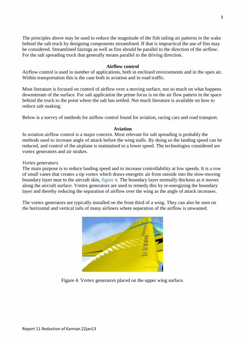
Aviation In aviation airflow control is a major concern. Most relevant for salt spreading is probably the methods used to increase angle of attack before the wing stalls. By doing so the landing speed can be reduced, and control of the airplane is maintained to a lower speed. The technologies considered are vortex generators and air strakes. Vortex generators The main purpose is to reduce landing speed and to increase controllability at low speeds. It is a row of small vanes that creates a tip vortex which draws energetic air from outside into the slow-moving boundary layer near to the aircraft skin, figure 4. The boundary layer normally thickens as it moves along the aircraft surface. Vortex generators are used to remedy this by re-energizing the boundary layer and thereby reducing the separation of airflow over the wing as the angle of attack increases. The vortex generators are typically installed on the front third of a wing. They can also be seen on the horizontal and vertical tails of many airliners where separation of the airflow is unwanted.
Figure 4. Vortex generators placed on the upper wing surface.

4
Report 11 Reduction of Karman 22jan13
Aircrafts may be provided with vortex generators from new, but there are also after-market suppliers who sell vertex generators to improve the slow velocity performance of light aircrafts, figure 5.
Figure 5. Vortex generators are available in many forms for installation on wings Air strake In aviation, the purpose of an air strake is to improve airflow and to reduce drag. It is simply a single, large vortex generator that is mounted on the fuselage, or more often on the engine nacelles. The strake creates a small energetic, swirling vortex that reduces the separation of airflow over the downstream wing surface at high angle of attack. During takeoff and landing the combination of high angle of attack and low speed may cause the flow of air to become erratic as it tries to move around the large nacelle, particularly in the region close to the fuselage or wing. The vortices created by the strake helps to reduce this separation of airflow over the downstream wing surface as its angle of attack increases.
Figure 6. Condensation vortices from a nacelle strake at takeoff In aviation the focus of airflow control is to reduce stall speed and reduce drag at high speeds. It is less on reducing turbulence in the wake although it is of major concern for reduction of spacing between aircrafts cleared for landing. No specific methods to this end have been found that may be applied to salt spreading, but the use of vertical air strikes at the lower, rear end of the truck may be considered.

5
Report 11 Reduction of Karman 22jan13
Racing cars The main purpose of aerodynamics for racing cars is to increase the down force on the car without increasing drag. A front and a rear wing is basically an inverted air foil that instead of lift produces a downward force. The wind creates an aerodynamic pressure on the upper surface and suction on the lower. The rear wing is positioned above the wake from the upstream part of the car for maximum efficiency, figure 7.
Figure 7. Example of the rear wing on a racer car The diffuser in the rear car underbody, figure 8, enhances the transition between the airflow underneath the car and the free stream airflow of the ambient atmosphere. It works by providing a space for the underbody airflow to expand without causing excessive flow separation and drag. The diffuser may also direct some air upwards increasing velocity at the underside of the rear wing and thus contribute to the down force
Figure 8. Example of rear diffuser on a racer car The principle from the racing cars is also being applied to personal cars as shown in figure 9. The diffusor is seen as a rounded rear end with curved fins to guide the air flow.
Figure 9. Example of a paneled underbody and rear diffuser on a car

6
Report 11 Reduction of Karman 22jan13
The idea of providing a space for the underbody airflow is to decelerate and expand without causing excessive flow separation and drag. The reduction in drag indicates that the level of turbulence near the road is reduced. This might be supplemented with vortex generators near the left and right side of the truck as shown for a car in figure 10.
Figure 10. Example of a rear diffusor and vortex generator under the rear end of a car
Road transport Airflow control is primarily considered as a means to reduce drag and thus fuel consumption in road transport. Vortex generators Lack of trailer streamlining causes a partial vacuum to form at the rear of the trailer at highway speeds. This causes turbulent air in the form of large eddies to tumble into the partial vacuum and the large alternating eddies cause the trailer to sway. Disturbances from passing vehicles or obstacles tend to amplify these eddies and increase the trailer's tendency to sway, increasing drag and lowering fuel economy. Streamlining the trailer would be the best solution but is not practical due to a necessary reduction in trailer capacity and massive changes to docking and loading facilities. A manufacturer claims that the use of their vortex generators may improve the truck stability by reducing the 'fish tailing' on trailers especially in gusty cross wind conditions or when passing or being passed by other vehicles. The vortex generators should be attached upstream of edges that cause turbulence and thus drag. The wishbone shaped vortex generators shown in figure 11 was designed to increase aerodynamic performance and fuel economy by reducing aerodynamic drag primarily at the tractor-trailer gap and the rear facing surface of square backed trucks or trailers. The vortex generator creates two tight swirls of air that reduce the suction and drag when traveling at speeds above approximately 55km/h. The swirls are approximately 4 to 5 times the height of the vortex generator that reaches 2.5 cm out from the surface. In order to be effective the airflow upstream therefore needs to be attached to the surface of the truck or the trailer, i.e. reach out of the stagnant boundary air in the boundary layer. The swirls of air can bridge the gap between tractor and trailer and let air flow more smoothly into the vacuum at the rear of the vehicle where they change the airflow from the alternating formation of large eddies to a line of dozens of small vigorous ones.

7
Report 11 Reduction of Karman 22jan13
Figure 11. A pre-manufactured vortex generator for trucks Installation of the vortex generators at the rear facing surface of a tanker and a trailer is shown in figure 12.
Figure 12. Vortex generators installed on the rear facing surface of a tanker and a trailer Streamlining the trailer by tapering is proposed as the best solution. Even if the energy savings are modest, the dissolution of large eddies into smaller stream wise eddies may be a worthwhile method of reducing salt snaking behavior at road level. To have effect within the short distance from the salt leaves the spreader till it comes to rest on the road, the vortex generators probably need to be placed closer to the road on the salt spreading truck than seen above. Trailer tail Most trailers have a near-vertical tailgate. Because of their shape, they have a large wake of disturbed air pulled along behind them. The result is high drag. This may be reduced by fitting a TrailerTail which is a commercial product comprising folding extension flaps that mount on frames attached to the rear doors of trailers. The extension flaps are angled inwards towards the centerline of the trailer. If the airflow remains attached until the trailing edges of these flaps, the resulting wake will be smaller, thus decreasing drag. The rear extensions will work only, however, if the flow remains attached to the flaps. An abrupt change of angle to more than 10° will most likely cause flow separation. In addition, the flow will remain attached only if the airflow is already attached to the body prior to the extension. So if the airflow has separated from the trailer ahead of the extension, the angled extension is unlikely to cause it to become re-attached. It appears from figure 13 that the trailing vortices created by the vertical rear edges have altered in their characteristics. The trailing vortices without the TrailerTail looks similar to the vortices that

8
Report 11 Reduction of Karman 22jan13
were developing immediately downstream of the cylinder shown earlier as a high frequency vortex street. The TrailerTail has suppressed the frequency of the vortex street in the wake further downstream. The figure shown is probably for middle height behind the trailer, and the velocity pattern may be different near the road. The shown effect is what is looked for as a means to reduce salt fishtailing, however.
Figure 13. TrailerTail and the effect on the trailing turbulence The Aerodynamic Truck & Trailer The Aerodynamics trailer shown in figure 14 is said to lower air resistance by around 18 per cent compared to an equivalent, regular truck. Numerous measures have been implemented including: the use of a spoiler that reduces the gap between truck and trailer; side trim panels; paneled underbody and a rear diffuser, and a rear taper. A solo truck called the Aerodynamic Truck was also designed similar to the Aerodynamic Trailer, using the same features.
Figure 14. Concept truck with optimized rear The side trim panels contribute improvement to the air resistance. They are slightly drawn-in at the front and characterized by an opening at the rear. This steers the air in the direction of the rear diffuser. The diffuser has the shape of a parallelogram and links up with the underbody paneling. The diffuser surrounds the rear underside guard and serves as a mount for the tail lamps. The principles applied to the Aerodynamic truck are interesting in the search for a solution to avoid salt snaking behind a salt spreader.

9
Report 11 Reduction of Karman 22jan13
Conclusions The magnitude of the fish tailing air patterns in the wake behind a salt spreading truck may be reduced by streamlining the truck and hopper. The use of fins may also be considered. Streamlined fairings as well as fins should be parallel to the direction of the airflow. For the salt spreading truck that generally means parallel to the driving direction. The boundary layer normally thickens as it moves along a surface. Vortex generators are used to re-energizing the boundary layer and create swirls of air that change the airflow at the rear of the truck from large eddies to lines of small vigorous ones. A diffuser in the rear car underbody provides a space for the underbody airflow to decelerate and expand without causing excessive flow separation and drag. The diffusor is a rounded underbody rear end with curved fins to guide the air flow. The Aerodynamic Truck is an example of how to reduce turbulence and drag using reduced gap between truck and trailer; side trim panels; paneled underbody; a rear diffuser, and a rear taper.
Literature Strøm, Jan S, 2012. Standardization of test method for salt spreader: Air flow experiments.
Report 9: Visualization of airflow patterns behind a full scale salt truck. Aarhus University, Engineering Centre Bygholm, Test and Development
Takai, Hisamitsu, 2012. Standardization of test method for salt spreader: Air flow experiments. Report 8: Observation of salt particle trajectory from spreader disc to road surface. Aarhus University, Engineering Centre Bygholm, Test and Development
Strøm, Jan S, 2011. Standardization of test method for salt spreader: Air flow experiments. Report 2: Visualization of airflow patterns. Aarhus University, Engineering Centre Bygholm, Test and Development
Figure 2. http://en.wikipedia.org/wiki/K%C3%A1rm%C3%A1n_vortex_street Figure 3. http://www.youtube.com/watch?v=bTcXGQ78cHM Figure 4. http://www.youtube.com/watch?v=z80pbIm3SoM&feature=related Figure 5. http://www.clubecav.com/2012/01/vortex.html and
http://www.hallwindmeter.com/vortex.php
Figure 6. http://frank.itlab.us/photo_essays/wrapper.php?apr_01_2010_sq22.html Figure 7. http://www.youtube.com/watch?v=2RWufDNN9hw&feature=related Figure 8. http://www.youtube.com/watch?feature=endscreen&v=6IVCtAso4T0&NR=1 Figure 9.
https://www.google.dk/search?q=racer+car+rear+diffuser&hl=en&tbo=u&tbm=isch&source=univ&sa=X&ei=nx7oUIyeOsjU4QTLw4HIBQ&ved=0CDIQsAQ&biw=1093&bih=514
Figure 10. http://www.varis.com.tw/bbs/board.php?bo_table=subaru&wr_id=74 Figure 11. http://autospeed.com/cms/A_3060/article.html?popularArticle and
http://www.youtube.com/watch?v=f80a9jssUFU&feature=related
Figure 12. http://www.airtab.com/gallery/trucks.html Figure 13. http://autospeed.com/cms/title_Reducing-the-drag-on-squareback-
cars/A_112656/article.html Figure 14. http://www.youtube.com/watch?v=VRCPJbyMv2k