standard tender documents section-7 general specifications ... · pdf filestandard tender...
TRANSCRIPT

Government of the People’s Republic of Bangladesh Ministry of Communications
Roads and Highways Department
STANDARD TENDER DOCUMENTS
SECTION-7
GENERAL SPECIFICATIONS (TECHNICAL SPECIFICATIONS)
July 2011


SECTION 7 GENERAL SPECIFICATIONS ABBREVIATIONS
I
INTRODUCTION
1. The Standard Tender Documents consists of the following:
Section-1 : Instructions to Tenderers (ITT). Section-2 : Tender Data Sheet (TDS). Section-3 : General Conditions of Contract (GCC). Section-4 : Particular Conditions of Contract (PCC). Section-5 : Tender and Contract Forms. Section-6 : Bill of Quantities (BOQ). Section-7 : General Specifications. Section-8 : Particular Specifications. Section-9 : Drawings.
2. This Specification forms Section-7 of the Roads and Highways Department’s Standard Tender Documents. It should be read in conjunction with the other documents which are Section-1, 2, 3, 4, 5, 6, 8 and 9.
3. The Specification calls up specific test methods to be adopted in the execution of quality control of the construction works, for example STP 4.3 for Standard Compaction of general earthwork embankment fills, and these standard test procedures are fully detailed in the Standard Test Procedures (STP) of the Bangladesh Road Research Laboratory, Mirpur, Dhaka.
4. This specification is split into Division 1 to 6, which are identified on the following pages. Each
Division is separated into specific sections with information on descriptions, specifications of materials, construction methods, methods of measurement and payment items being given. The item numbers included in section-7 are reproduced for pricing the Bill of Quantities (BOQ) from Division-1 to 6 which is considered to be part of the Tender Document.
5. The Contractor is required to comply fully with all aspects of this Specification and should not
assume that constructional plant and equipment will be available from the Roads and Highways Department and shall allow for obtaining constructional plant and equipment from other sources.
6. The Contractor is responsible for ensuring that the necessary tests and measurements are
carried out in order to ensure that the work complies with the Specifications. The Contractor shall give a minimum of 24 hours notice in writing to the Engineer of each item of work to be covered or buried. The contractor should make due allowance in his programme of work for all necessary testing of the works in accordance with these Specifications and the Particular Specifications. Any work undertaken not in accordance with these conditions may be rejected by the Engineer.

SECTION 7 GENERAL SPECIFICATIONS ABBREVIATIONS
I
SECTION 7 – GENERAL SPECIFICATIONS CONTENTS ABBREVIATIONS DIVISION 1 GENERAL AND SITE FACILITIES DIVISION 2 EARTHWORK DIVISION 3 PAVEMENT WORK DIVISION 4 FOUNDATION WORK DIVISION 5 STRUCTURES DIVISION 6 INCIDENTALS

SECTION 7 GENERAL SPECIFICATIONS ABBREVIATIONS
I
ABBREVIATIONS
AASHTO American Association of State Highway and Transportation Officials ASTM American Society of Testing and Materials BSTI Bangladesh Standards Testing Institute BR Bangladesh Railways REB Rural Electrification Board BRRL Bangladesh Road Research Laboratory BS British Standard CBR California Bearing Ratio HWL High Water Level IP International Petroleum Society JIS Japan Industrial Standard LWL Low Water Level MSL Mean Sea Level PVC Polyvinyl Chloride RHD Roads and Highways Department ROW Right of Way STP Standard Laboratory Test Procedures for Quality Control Laboratories, BRRL

SECTION 7 GENERAL SPECIFICATIONS DIVISION 1- GENERAL AND SITE FACILITIES
DIVISION 1
GENERAL AND SITE FACILITIES

SECTION 7 GENERAL SPECIFICATIONS DIVISION 1 - GENERAL AND SITE FACILITIES CONTENTS
July 2011
DIVISION 1 - GENERAL AND SITE FACILITIES
Page 1.1 MAINTENANCE AND PROTECTION OF TRAFFIC ....................................................... 1
1.1.1 General ................................................................................................................... 1 1.1.2 Measurement and Payment .................................................................................. 2
1.2 FIELD OFFICE FOR THE ENGINEER AND OTHER FACILITIES TO BE PROVIDED BY THE CONTRACTOR ................................................................................................. 3
1.2.1 Field Office for the Engineer and his Staff .......................................................... 3 1.2.2 Sanitation ............................................................................................................... 3 1.2.3 Office Equipment and Consumables ................................................................... 4 1.2.4 Sign Boards ........................................................................................................... 4 1.2.5 Survey Equipment ................................................................................................. 4
1.2.5.1 Levels and Levelling Staffs ................................................................................ 5 1.2.5.2 Theodolites ........................................................................................................ 5 1.2.5.3 Electronic Distance Measurer (EDM) ................................................................ 5
1.2.6 Insurance of Engineer’s Field Office, Furniture and Equipment ....................... 5 1.2.7 Progress Photographs .......................................................................................... 5 1.2.8 Measurement and Payment .................................................................................. 6
1.3 TESTING OF MATERIALS .............................................................................................. 7
1.3.1 Contractor’s Site Laboratory ................................................................................ 7 1.3.2 Materials Testing by Independent Laboratories ................................................. 7 1.3.3 Special and Additional Testing............................................................................. 8 1.3.4 Staff for Materials Testing ..................................................................................... 8 1.3.5 Test Results and Records ..................................................................................... 9 1.3.6 Measurement and Payment .................................................................................. 9
1.4 TRANSPORT FOR THE ENGINEER ............................................................................ 10
1.4.1 General ................................................................................................................. 10 1.4.2 Items of Transport ............................................................................................... 10 1.4.3 Measurement and Payment ................................................................................ 10
1.5 RELOCATION OF PUBLIC UTILITIES ......................................................................... 11
1.5.1 Description ........................................................................................................... 11 1.5.2 Measurement and Payment ................................................................................ 11
1.6 GENERAL CONTRACTOR’S OBLIGATIONS .............................................................. 12 1.6.1 Site Establishment, Maintenance and Demobilisation ..................................... 12 1.6.2 Provision of Performance Bond ..................................................................... 12 1.6.3 Provision of Insurances ...................................................................................... 12 1.6.4 As-Built Drawings ................................................................................................ 12 1.6.5 Measurement and Payment ................................................................................ 12

SECTION 7 GENERAL SPECIFICATIONS GENERAL AND SITE FACILITIES
July 2011 Page 1.1
1.1 MAINTENANCE AND PROTECTION OF TRAFFIC 1.1.1 General
The Contractor shall at all times maintain the traffic flow along existing roads, rivers and canals and take all necessary measures for the safety of traffic, pedestrians and workers. The Contractor shall provide, erect, operate and maintain signs, markings, lights, barricades and traffic control equipment in accordance with the Bangladesh Road Transport Authority’s Traffic Signs Manual, unless otherwise directed by the Engineer. The Contractor shall provide and maintain all detours, temporary roads, temporary bridges, necessary barricades, warning lights and signs as well as other equipment at all hours during the day or night. The Engineer’s approval of plan and section drawings of proposed detours, temporary roads and temporary bridges shall be obtained by the Contractor before any work is commenced. Where the work site takes up part of the road only, and the full width of the road can be restored for night time traffic, the Engineer may give permission for control of the traffic through the works area by use of flagmen or electronically controlled mobile traffic lights, without the need for construction of bypass roads, but the Engineer’s approval will only be given if, and while, the Contractor demonstrates that sufficient resources are applied and maintained for this purpose. Where construction interferes with the existing roads, track and footpaths, other than as noted above, provision shall be made to a similar standard that existed prior to the works for the free movement of traffic and pedestrians. The Contractor shall take all necessary steps to avoid or minimise delays and inconvenience to road users during the course of the works. Notwithstanding the above any diversion of the National and Regional Highways shall comply to at least the minimum standard stated as following:
• Minimum carriageway width of 7.3 metres. • Minimum horizontal radius of 150 metres. • Maximum gradient of 1 in 33. • The construction shall be sufficient for the smooth uninterrupted passage of all traffic and
have a bituminous surface.
Notwithstanding the above any diversion of Feeder Roads shall comply to at least the minimum standard stated as following:
• Minimum carriageway width of 5.50 metres. • Minimum horizontal radius of 100 metres. • Maximum gradient of 1 in 33. • All weather surfaces.
The Contractor shall supply all temporary signs, lights and other equipment, to the approval of the Engineer, to ensure smooth and safe flows of traffic. Also the Contractor shall take all reasonable precautions to prevent damage to vehicles from construction equipment or materials and shall be responsible for any claims arising from such damage. The Contractor shall in due time and at least seven days before any diversion, interruption or impediment to traffic takes place, submit a detailed stage programme for the Engineer’s approval. The programme shall show all arrangements necessary to ensure a smooth traffic flow. Upon completion of the Works, all temporary roads, temporary bridges, barricades, signs and other equipment shall be completely removed, unless otherwise approved in writing by the Engineer. From the date of Commencement of the Contract to the date of the Completion or Partial Completion Certificate the Contractor shall also be responsible for maintenance of, and repair of damage, to all existing features, constructions, structures, pavements etc. which come

SECTION 7 GENERAL SPECIFICATIONS GENERAL AND SITE FACILITIES
July 2011 Page 1.2
within the limits of the site irrespective of the cause of the damage, unless that cause is determined to be an accepted risk and the repairs are determined to be a compensation event.
If in the opinion of the Engineer the Contractor has failed to properly repair or maintain existing or temporary construction, or provide sufficient or appropriate warning signs, lights, barricades etc. he shall instruct the Contractor, in writing, to provide such signs as he considers appropriate for protection of traffic, pedestrians, employees and the works. If the Contractor fails to respond within the time given by the Engineer, the Engineer may suspend works which interfere with traffic until such time as the Contractor provides sufficient signs etc. as the Engineer has directed, or the Engineer may arrange to provide the required signs etc. at cost to the Contractor, these costs being deducted from monies due to the Contractor under the Contract. These costs will include any costs for missing or stolen items not returned to the Engineer at the completion of works or when replaced by the Contractor.
1.1.2 Measurement and Payment The construction and ultimate removal of all temporary constructions as well as the provision of barricades, signs and other equipment shall be paid for at a lump sum price. This sum shall cover all earthworks, temporary bridging and culverts, pavement and surfacing materials, warning signs, lights, control of traffic including single lane working, by day and by night, and all other items to ensure the smooth and safe flow of traffic. Where temporary bridging materials, such as Bailey Bridge components are supplied to the Contractor, these will be delivered to the Site. The Contractor shall be responsible for the care of all materials supplied to him and shall bear all costs associated with repair and replacement due to damage and loss. The maintenance and repair of existing and temporary constructions, and equipment provided for the maintenance and protection of traffic flows shall be paid for at a daily rate. When the Engineer issues an instruction requiring the Contractor to provide; repairs, maintenance, or additional temporary signs, lights, barricades or any other such feature, every day the Contractor fails to comply with the instruction to the satisfaction of the Engineer, the day shall not be included for payment and a corresponding pro rata deduction shall be made to the Lump Sum for establishment of temporary construction and provision of signs etc. noted above. This means that for every day the Contractor fails to comply with the Engineer’s instruction there will be no payment made for establishment and maintenance of temporary works and signs for the whole of the site. Additional fill material used for temporary diversions outside the lines shown on the cross sections and plans for the permanent works may be allowed to remain in place on completion of the Works, provided it is trimmed to levels and slopes approved in writing by the Engineer and all additional costs such as extending drainage and for additional grassing to shoulders and side slopes are at the cost of the Contractor.
Pay items shall be: 1/1/1 Provision, Construction and Removal, as applicable, of Lump Sum Temporary Roads, Structures etc. and Equipment for the Maintenance and Protection of Traffic. (Applicable deduction for days of non-compliance with an Engineer’s direction for additional traffic control requirements equals the Lump Sum tendered divided by the construction period in days) 1/1/2 Maintain Temporary Structures and Equipment for Day the Maintenance and Protection of Traffic

SECTION 7 GENERAL SPECIFICATIONS GENERAL AND SITE FACILITIES
July 2011 Page 1.3
1.2 FIELD OFFICE FOR THE ENGINEER AND OTHER FACILITIES TO BE PROVIDED BY THE CONTRACTOR
1.2.1 Field Office for the Engineer and his Staff
In addition to the office space required for his own use, the Contractor shall provide and maintain a furnished field office for the use of the Engineer and his staff. Requirements for the office, including overall size, number and size of individual rooms, construction and furniture are stated in Particular Specifications Clause 1.2.1 in Section 6 of Volume 1 - The Tender. The field office shall be maintained in a secure and watertight condition by the Contractor until completion of the Works or as otherwise instructed by the Engineer and shall be provided with electricity, running water and sewerage. All doors shall be fitted with approved locks, and windows shall be provided with mosquito screens and blinds and shall have interior locking devices. The Contractor shall submit for the approval of the Engineer before construction, plans and drawings showing proposed details and location for the field office, including foundations, access roads, shades, layout of electrical and water supplies and hard standings thereto. The Engineer may require revision of the plans prior to giving approval for construction. The Contractor shall also submit details of proposed furniture and fittings to the Engineer for approval. These items shall generally be of the best quality obtainable locally. The office, complete with furnishings, fittings, access roads and hard standings shall be ready for occupation by the Engineer within four weeks of the date when the Contractor first occupies the site. The Contractor will provide all necessary MLSS (Members of Lower Service Staff) for the field office, including day and night security guards and a tea boy. The Contractor will also provide a competent computer operator. Staff considered unsuitable by the Engineer shall be replaced. The Contractor shall arrange for the field office to be regularly and properly cleaned and for access roads and hard standings to be maintained in a well drained and trafficable condition. All furnishings and fittings in the field office shall also be maintained by the Contractor in working condition and to the approval of the Engineer. All materials recovered from dismantling the office and removing access roads, hard standings etc., should be stockpiled on site as approved by the Engineer and along with all furniture and fittings will be the property of the Employer. Where suitable buildings are available within the general limits of the site of the works the Contractor may propose to the Engineer that the buildings be rented. The buildings must conform with all the criteria above and if deemed to be satisfactory, the Engineer may accept their use as offices.
1.2.2 Sanitation
The Contractor shall provide adequate water-borne sanitation and refuse collection and disposal, complying with the Laws of Bangladesh and all local By-Laws, and to the satisfaction of the Engineer, for all offices, laboratories, workshops, houses etc. erected on the Site.

SECTION 7 GENERAL SPECIFICATIONS GENERAL AND SITE FACILITIES
July 2011 Page 1.4
1.2.3 Office Equipment and Consumables
The Contractor shall provide and maintain the office equipment such as photocopy machines and computers for the Engineer’s field office as listed in Particular Specifications Clause 1.2.3 in Section 6 of Volume 1-The Tender. Equipment supplied will be subject to the approval by the Engineer. The Contractor shall supply all consumables related to the equipment and arrange for the equipment to be maintained, including servicing at intervals recommended by the respective manufacturers. Upon completion of the Works or as otherwise instructed by the Engineer, the equipment shall become the property of the Contractor. The Contractor shall provide and maintain in working order/good condition, as applicable, the items of kitchen equipment listed in Particular Specifications Clause 1.2.3 in Section 6 of Volume 1-The Tender. The Contractor shall provide all standard stationery items to the Engineer’s field office, along with kitchen and bathroom supplies as may be required by the Engineer throughout the duration of the contract.
1.2.4 Sign Boards
The Contractor shall provide identification sign boards, of the number and size stated in Particular Specifications Clause 1.2.4 in Section 6 of Volume 1-The Tender, and maintain them in good condition. All information on the signboards will be written in English and Bengali. The signboards will be positioned as directed by the Engineer. The Contractor shall submit proposals for the materials of the signboards, the text layout and installation of the signboards on Site to the Engineer for approval. Each sign shall show: • the name of the Project • the name of the Employer • all other details as required by the Engineer The Contractor shall remove the sign boards on completion of the Works or when instructed by the Engineer
1.2.5 Survey Equipment
The Contractor will be required to provide survey equipment for the use of the Contractor’s and Engineer’s staff. The description of the main items required is given in Sections 1.2.5.1 to 1.2.5.3. The numbers of each item to be provided are stated in Particular Specifications Clause 1.2.5 in Section 6 of Volume 1-The Tender. The Contractor shall provide manufacturers published specifications of proposed survey equipment for the approval of the Engineer and shall ensure that equipment supplied to Site is maintained in good working order. In addition to the survey equipment specified in Sections 1.2.5.1 to 1.2.5.3, the Contractor shall supply miscellaneous tools and minor items of survey equipment such as 30 m and 3 m long steel tapes, ranging rods, spirit levels, plumb bobs, umbrellas, hammers, knives, wooden stakes, steel pins, string lines, paint, marking crayons etc. to the Site. These shall be available in reasonable quantities at all times for use by the Contractor’s and Engineer’s staff. Ranging rods shall be 1.8 m long with alternate red and white painting. They shall be true and straight with a steel pointed tip to one end. The Contractor shall supply the required manpower to the Engineer to assist with survey and setting out works, as and when required.

SECTION 7 GENERAL SPECIFICATIONS GENERAL AND SITE FACILITIES
July 2011 Page 1.5
On completion of the Works or as otherwise instructed by the Engineer, all survey equipment shall remain the property of the Contractor.
1.2.5.1 Levels and Levelling Staffs
Levels shall be autoset in carrying cases, complete with centering tripods with extension legs, and to the following minimum specifications: Magnification 32 times Stadia 1:100 Aperture 40 mm minimum Resolving power 3”(sec) Angular field of view 1o 20' Range of sensitivity ±15 minutes or less Short Focusing Distance 1 m Horizontal circle diameter 75 mm Addition constant 0 Graduation 10 minutes Accuracy ± 1mm for 1km double run Staffs shall be telescopic, aluminium with graduations in Metric units.
1.2.5.2 Theodolites
Theodolites shall be double circle Triangulation Theodolites with optical Micrometers. The instruments shall be in airtight metal/wooden carrying cases with tool compartments and eyepiece filters complete with centering tripods and extension legs, to the following minimum specifications. One or more theodolites suitable for the attachment of an EDM may be required. Objective aperture 45 mm Addition constant 0 Shortest focusing distance 1.7 m Sensitivity of collimation level 20"/2 mm Multiplication constant 100 Graduations 360o
1.2.5.3 Electronic Distance Measurer (EDM)
EDM’s shall be supplied with full accessories including legs, reflectors and stands, rechargeable batteries and charger and shall be to the following minimum specification. Distance measurement: Range not less than 1500 m Accuracy + (5 mm = 5 pmm) mse Telescope: Image/Mag: Erect 30 X Min focus 1.5 m Angle Measurement: Method: Electronic or Optical Direct Reading to 5" Automatic Vertical Index: Range + 5' Setting Accuracy + 0.25" Weight including case: Less than 15 kg
1.2.6 Insurance of Engineer’s Field Office, Furniture and Equipment
The Contractor shall insure the Engineer’s field office, furniture, office equipment and survey equipment against loss or damage by accident, fire or theft for the duration of the Contract.
1.2.7 Progress Photographs
Each month on a date to be agreed with the Engineer, the Contractor shall arrange to take a series of not less than 20 and not more than 40 colour photographs which record the progress of the Works. Two complete sets of prints of approximate size 175 mm x 125 mm plus the negatives shall be supplied to the Engineer by the Contractor within one week of each series of

SECTION 7 GENERAL SPECIFICATIONS GENERAL AND SITE FACILITIES
July 2011 Page 1.6
photographs being taken. A list shall accompany the photographs, indicating the date when the photographs were taken and a short description of the photographs, against the negative numbers. The photographs shall be taken by an approved professional photographer, accompanied by representatives of the Engineer and the Contractor. If, for any reason, the Engineer is not satisfied with any of the photographs, the Contractor shall arrange at his cost for further photographs to be taken.
1.2.8 Measurement and Payment
Supplying materials for and constructing the field office for the Engineer, including all furniture and fittings, access roads, car parking shades etc., and the provision of water, electricity and sewerage facilities, and the removal of the field office at the end of the Contract, as described in Specifications Sections 1.2.1 and 1.2.2 and Particular Specifications Clause 1.2.1 in Section 6 of Volume 1-The Tender shall be paid for at a lump sum price. The maintenance, cleaning and security of the field office for the Engineer, the provision of MLSS (chowkhidars and a tea boy), the provision of a typist / computer operator and the cost of water, electricity and sewerage shall be paid for at a monthly rate. The provision of office equipment, consumables and insurance as described in Specifications Sections 1.2.3 and 1.2.6 and Particular Specifications Clause 1.2.3 shall be paid for at a monthly rate. Payment for the provision, maintenance and removal of sign boards as described in Specifications Section 1.2.4 and Particular Specifications Clause 1.2.4 in Section 6 of Volume 1-The Tender shall be on a Lump Sum basis. Payment for the provision, maintenance and insurance of survey equipment and the provision of approval personnel as described in Specifications Sections 1.2.5 and 1.2.6 and Particular Specifications Clause 1.2.5 in Section 6 of Volume 1-The Tender shall be at a monthly rate. Payment for the provision of progress photographs as described in Specifications Section 1.2.7 shall be at a monthly rate. Pay items shall be: 1/2/1 Supply, Erect and Remove Field Office for Lump Sum the Engineer 1/2/2 Maintenance, Staffing, Security and Cleaning of the Month Field Office for the Engineer 1/2/3 Provision of Office Equipment and Consumables Month 1/2/4 Provision, Maintenance and Removal of Sign Boards Lump Sum 1/2/5 Provision and Maintenance of Survey Equipment Month 1/2/6 Provision of Insurance for the Engineer’s Office, Month Furniture and Equipment. 1/2/7 Progress Photographs Month
SECTION 7 GENERAL SPECIFICATIONS GENERAL AND SITE FACILITIES
July 2011 Page 1.7
1.3 TESTING OF MATERIALS
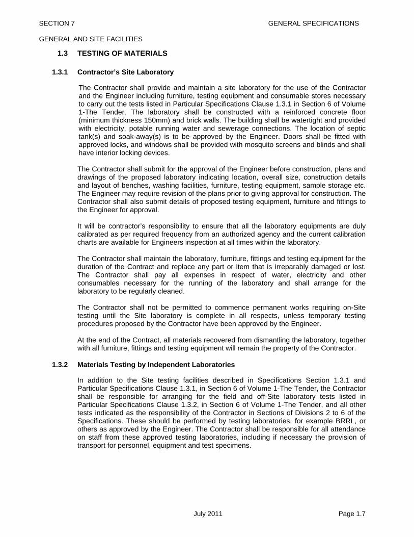
1.3.1 Contractor’s Site Laboratory
The Contractor shall provide and maintain a site laboratory for the use of the Contractor and the Engineer including furniture, testing equipment and consumable stores necessary to carry out the tests listed in Particular Specifications Clause 1.3.1 in Section 6 of Volume 1-The Tender. The laboratory shall be constructed with a reinforced concrete floor (minimum thickness 150mm) and brick walls. The building shall be watertight and provided with electricity, potable running water and sewerage connections. The location of septic tank(s) and soak-away(s) is to be approved by the Engineer. Doors shall be fitted with approved locks, and windows shall be provided with mosquito screens and blinds and shall have interior locking devices. The Contractor shall submit for the approval of the Engineer before construction, plans and drawings of the proposed laboratory indicating location, overall size, construction details and layout of benches, washing facilities, furniture, testing equipment, sample storage etc. The Engineer may require revision of the plans prior to giving approval for construction. The Contractor shall also submit details of proposed testing equipment, furniture and fittings to the Engineer for approval. It will be contractor’s responsibility to ensure that all the laboratory equipments are duly calibrated as per required frequency from an authorized agency and the current calibration charts are available for Engineers inspection at all times within the laboratory. The Contractor shall maintain the laboratory, furniture, fittings and testing equipment for the duration of the Contract and replace any part or item that is irreparably damaged or lost. The Contractor shall pay all expenses in respect of water, electricity and other consumables necessary for the running of the laboratory and shall arrange for the laboratory to be regularly cleaned. The Contractor shall not be permitted to commence permanent works requiring on-Site testing until the Site laboratory is complete in all respects, unless temporary testing procedures proposed by the Contractor have been approved by the Engineer. At the end of the Contract, all materials recovered from dismantling the laboratory, together with all furniture, fittings and testing equipment will remain the property of the Contractor.
1.3.2 Materials Testing by Independent Laboratories
In addition to the Site testing facilities described in Specifications Section 1.3.1 and Particular Specifications Clause 1.3.1, in Section 6 of Volume 1-The Tender, the Contractor shall be responsible for arranging for the field and off-Site laboratory tests listed in Particular Specifications Clause 1.3.2, in Section 6 of Volume 1-The Tender, and all other tests indicated as the responsibility of the Contractor in Sections of Divisions 2 to 6 of the Specifications. These should be performed by testing laboratories, for example BRRL, or others as approved by the Engineer. The Contractor shall be responsible for all attendance on staff from these approved testing laboratories, including if necessary the provision of transport for personnel, equipment and test specimens.

SECTION 7 GENERAL SPECIFICATIONS GENERAL AND SITE FACILITIES
July 2011 Page 1.8
1.3.3 Special and Additional Testing
In addition to the testing described in Specifications Sections 1.3.1 and 1.3.2, the Engineer may require further testing to be carried out. Such special and additional testing shall be arranged by the Contractor under the direction of the Engineer.
1.3.4 Staff for Materials Testing
The Contractor shall provide qualified laboratory engineers, technicians, assistants, labourers, etc. to carry out sampling and testing of materials in accordance with Specifications Sections 1.3.1, 1.3.2 and 1.3.3. Laboratory staff shall be subject to the approval of the Engineer and be available to assist the Engineer with materials testing, as and when required.
1.3.5 Sampling and Testing
The frequency of test requirements for pavement layers, bitumen and concrete mixes should comply to those in Table 1.3-1. Table 1.3-1 Frequency of Tests
Washed Grading
(STP 3.3 / 7.2)
Atterberg Limits
(STP 3.2)
Max Dry Density /
CBR
(STP 4.3 / 4.5, 5.1)
In-situ Density
(STP 6.2)
ACV, 10% Fines and LAA (STP
7.7.1, 7.7.2, AASHTO T96)
Earthworks 1/2000 m3 1/2000 m3 1/1000 m2
Improved Sub-Grade 1/1000 m3 1/1000 m3 1/1000 m3 3/1000 m2
Sub-Base 1/750 m3 1/750 m3 1/750 m3 3/1000 m2 1/2000 m3
Base 1/500 m3 1/500 m3 1/500 m3 3/1000 m2 1/1000 m3
For Bituminous and Concrete Mixes 1 set of tests per 100 cum of aggregate for shape (STP 7.3), grading (STP 7.2), ACV , 10% Fines and Los Angeles Abrasion Value (STP 7.7.1, 7.7.2 and AASTO T96) should be carried out. If crushed gravel is used as coarse aggregate, percentage of fractured faces shall be checked 1 test per 100 cum. Water absorption, Soundness and Coating & Stripping Test should be carried out 1 test for each source/type of aggregate at the start of work and subsequently on every change in quality of aggregate. Sand Equivalent Value for the fine aggregate for bituminous mixes shall be determined minimum 1 test / 100 cum. Grading of filler (STP 7.2) for bituminous mixes should be checked 1 test / 20 tons of filler. Water Sensitivity Test should be carried out on the bituminous mixes as per AASHTO-T283 at the time of mix design and subsequently as and when required by the Engineer. Dynamic cone Penetrometer (DCP) should be carried out in addition to the density test for each layer of Embankment and Subgrade 1 test / 500 sqm. The Contractor shall maintain complete records of test results, which may be inspected by the Engineer at any time. All test results shall be recorded on standard forms approved by

SECTION 7 GENERAL SPECIFICATIONS GENERAL AND SITE FACILITIES
July 2011 Page 1.9
the Engineer and shall be signed by the Contractor’s engineer or technician in charge of the laboratory. Completed forms shall clearly show the locations of samples, sampling dates and testing dates. Samples shall be numbered serially at the time of sampling. A copy of all test results should be submitted to the Engineer immediately after completion of the test. The Engineer will be informed prior to any sampling or testing carried out in the laboratory and will have the right to use the facilities and equipment to make his own tests. The Contractor shall have the right to witness any sampling or testing carried out by the Engineer. On completion of the Contract the original copies of all test results shall be handed over to the Employer, via the Engineer.
1.3.6 Measurement and Payment
The provision of the laboratory, furniture, equipment and services detailed in Specifications Section 1.3.1 and Particular Specifications Clause 1.3.1, in Section 6 of Volume 1-The Tender, and the removal from Site of the laboratory, furniture and equipment at the end of the Contract shall be paid for at a lump sum price. Maintenance of the site laboratory, furniture and equipment shall be paid for at a monthly rate. The sampling and testing carried out by the Contractor in accordance with Specifications Sections 1.3.1, 1.3.2, 1.3.4 and 1.3.5 is included in the pay items for the respective work in Divisions 2 to 6 of the Specifications. Payment for special or additional tests described in Specifications Section 1.3.3, shall be under a provisional sum, unless the costs of such tests are to be borne by the Contractor in accordance with Clause 35.4 of Volume 2 - Conditions of Contract. Pay items shall be: 1/3/1 Provide and Remove Site Laboratory and Equipment Lump Sum 1/3/2 Maintain Site Laboratory Month 1/3/3 Special or Additional Tests Provisional Sum

SECTION 7 GENERAL SPECIFICATIONS GENERAL AND SITE FACILITIES
July 2011 Page 1.10
1.4 TRANSPORT FOR THE ENGINEER
1.4.1 General
The Contractor shall provide and maintain road and river transport for the exclusive use of the Engineer, his representatives and representatives of the Employer.
1.4.2 Items of Transport
Road transport, which shall be used both on and off the Site, shall include saloon cars of 1200 cc capacity, double cab pick-ups, four wheel drive vehicles with a minimum of 6 seats and motor cycles of 125 cc capacity. River transport shall be motor boats of minimum length 5 m suitable for carrying out survey and inspection work and shall have covered deck areas to give protection from the sun and rain. No persons of either the Engineer’s or Contractor’s staff other than authorised boatmen shall be allowed to operate the boats. The Bill of Quantities indicates the requirements for road and river transport. When items of transport are out of use for repairs, servicing etc., equivalent substitutes shall be provided by the contractor. Items of transport and drivers or boatmen considered unsuitable by the Engineer shall be replaced.
1.4.3 Measurement and Payment
The Contractor’s monthly rate for the provision and maintenance of vehicles and motor cycles shall include fuel, servicing, maintenance, drivers wages, taxes, duties, registration, insurance etc., as applicable. The Contractor’s monthly rate for the provision of motor boats shall include fuel, servicing, maintenance, experienced boatmen’s wages, taxes, duties, registration, insurance, etc. All boats shall be provided with life belts, life jackets and navigation and warning lights. Pay items shall be: 1/4/1 Saloon Car 1200 cc Capacity Month 1/4/2 Pick-up (Double Cab) Month 1/4/3 Four Wheel Drive Vehicle minimum 6 seats Month 1/4/4 Motor Cycle 125 cc Month 1/4/5 Motor Boat minimum 5 metre length Month

SECTION 7 GENERAL SPECIFICATIONS GENERAL AND SITE FACILITIES
July 2011 Page 1.11
1.5 RELOCATION OF PUBLIC UTILITIES
1.5.1 Description
The Contractor shall be responsible for establishing the locations of all public utilities within the Site of the Works, and for their protection. Where the necessity for the permanent relocation of public utilities has been identified, details will be indicated on the Drawings. Should the Contractor consider that the temporary diversion of public utilities is necessary in order to carry out Contract works, he shall submit details of his proposals to the Engineer. Relocation works will normally be undertaken by the concerned authorities, with which the Contractor will be expected to liaise. The Contractor shall indicate relocation works in his Contract Programme.
1.5.2 Measurement and Payment
The Contractor should include for costs associated with the location and protection of public utilities and the temporary diversion of public utilities in his pricing. Payment for the necessary permanent relocation of public utilities will be under a provisional sum. Pay items shall be: 1/5/1 Relocation of Public Utilities Provisional Sum

SECTION 7 GENERAL SPECIFICATIONS GENERAL AND SITE FACILITIES
July 2011 Page 1.12
1.6 GENERAL CONTRACTOR’S OBLIGATIONS
1.6.1 Site Establishment, Maintenance and Demobilisation
The Contractor is to allow for the provision, maintenance and removal at the end of the Contract of all offices, stores, covered workshops, canteens, toilet facilities etc. for his own use, required to execute the Works in accordance with the Contract Documents. In addition, the Contractor is to allow for complying with his obligations for safety, security and protection of the environment described in the Contract Documents including in Sub-Clauses 17.1 and 18.1 of Volume 2 - Conditions of Contract.
1.6.2 Provision of Performance Security
This item is for the provision by the Contractor of the Performance Security, the requirements of which are stated in Clause 43 of Volume 2 – Conditions of Contract.
1.6.3 Provision of Insurances
This item is for the provision of insurances as required in accordance with Clauses 11, 13 and 53 of Volume 2 - Conditions of Contract. The minimum amount of third party insurance shall be as stated in the Contract Data in Section 4 of Volume 1-The Tender. Failure to provide insurance will result in no interim payments.
1.6.4 As-Built Drawings
The Contractor shall furnish sets of as-built Drawings of the Works to the Engineer, showing the permanent works as actually constructed, within one month of completion of the Works. Included in the sets of as-built Drawings will be revisions of Tender Drawings and Drawings supplied to the Contractor during the Contract as well as revisions of drawings supplied by the Contractor during the Contract. The As-built drawings submitted by the Contractor will be subject to the approval of the Engineer. For specific requirements for the As-built Drawings refer to Particular Specifications Clause 1.6.4 in Section 6 of Volume 1 – The Tender.
1.6.5 Measurement and Payment
Payment for these items will be deemed to be included for by the contractor in his rates for the Works unless otherwise provided for in Clause 25 of the Contract Data in Section 4 of Volume 1 – The Tender.

SECTION 7 GENERAL SPECIFICATIONS DIVISION 2- EARTHWORK
DIVISION 2 EARTHWORK

SECTION 7 GENERAL SPECIFICATIONS DIVISION 2 – EARTHWORKS CONTENTS
July 2011
DIVISION 2 - EARTHWORK
Page 2.1 CLEARING AND GRUBBING ........................................................................................... 1
2.1.1 Description ................................................................................................................ 1 2.1.2 Preservation of Property .......................................................................................... 1 2.1.3 Construction Methods .............................................................................................. 1
2.1.3.1 Clearing ................................................................................................................ 1 2.1.3.2 Grubbing ............................................................................................................... 1 2.1.3.3 Ownership of Cleared Material ............................................................................. 1 2.1.3.4 Existing Drainage ................................................................................................. 2
2.1.4 Measurement ............................................................................................................. 2 2.1.5 Payment ..................................................................................................................... 2
2.2 ROADWAY EXCAVATION ................................................................................................ 3
2.2.1 Description ................................................................................................................ 3 2.2.2 Materials .................................................................................................................... 3 2.2.3 Construction Methods .............................................................................................. 4
2.2.3.1 General ................................................................................................................. 4 2.2.3.2 Excavated Material Used in the Works ................................................................. 4 2.2.3.3 Unsuitable Material from Roadway Excavation .................................................... 4 2.2.3.4 Excess Suitable Excavated Material ..................................................................... 4 2.2.3.5 Excavation of Unsuitable Soil ............................................................................... 4 2.2.3.6 Slopes .................................................................................................................. 4 2.2.3.7 Drainage ............................................................................................................... 4 2.2.3.8 Preparation of Excavated Areas ........................................................................... 4
2.2.4 Measurement ............................................................................................................. 5 2.2.5 Payment ..................................................................................................................... 5
2.3 BORROW .......................................................................................................................... 6
2.3.1 Description ................................................................................................................ 6 2.3.2 Acquisition and Use of Borrow Pits ........................................................................ 6
2.3.2.1 Borrow Pits within the Right-of-Way ..................................................................... 6 2.3.2.2 Borrow Pits Outside the Right-of-Way .................................................................. 6
2.3.3 Construction Methods .............................................................................................. 6 2.3.4 Measurement and Payment ..................................................................................... 6
2.4 CHANNEL EXCAVATION ................................................................................................. 7
2.4.1 Description ................................................................................................................ 7 2.4.2 Materials .................................................................................................................... 7 2.4.3 Construction Methods .............................................................................................. 7
2.4.3.1 Alignment and Levels ........................................................................................... 7 2.4.3.2 Excavation ............................................................................................................ 7 2.4.3.3 Filling of Obsolete Channels ................................................................................. 7 2.4.3.4 Unsuitable Excavated Material ............................................................................. 7 2.4.3.5 Excess Suitable Excavated Material ..................................................................... 7
2.4.4 Measurement ............................................................................................................. 8 2.4.5 Payment ..................................................................................................................... 9
2.5 EXCAVATION AND BACKFILL FOR STRUCTURES .................................................... 10
2.5.1 Description .............................................................................................................. 10 2.5.2 Materials .................................................................................................................. 10
2.5.2.1 Foundation Fill Material ...................................................................................... 10 2.5.2.2 Backfill Material .................................................................................................. 10
DIVISION 2 - EARTHWORK

SECTION 7 GENERAL SPECIFICATIONS DIVISION 2 – EARTHWORKS CONTENTS
July 2011
2.5.3 Construction Methods ............................................................................................ 10
2.5.3.1 Clearing .............................................................................................................. 10 2.5.3.2 Excavation .......................................................................................................... 10 2.5.3.3 Disposal of Excavated Material .......................................................................... 11 2.5.3.4 Cofferdams ......................................................................................................... 11 2.5.3.5 Pumping and Bailing ........................................................................................... 13 2.5.3.6 Backfilling ........................................................................................................... 13
2.5.4 Measurement ........................................................................................................... 14 2.5.5 Payment ................................................................................................................... 14
2.6 EMBANKMENT ............................................................................................................... 16
2.6.1 Description .............................................................................................................. 16 2.6.2 Materials .................................................................................................................. 16 2.6.3 Construction Methods ............................................................................................ 16
2.6.3.1 Preparation of Foundations for Embankment ..................................................... 16 2.6.3.2 Placing Embankment .......................................................................................... 16 2.6.3.3 Compaction of Embankment .............................................................................. 17
2.6.4 Measurement ........................................................................................................... 18 2.6.5 Payment ................................................................................................................... 18
2.7 PREPARATION OF SUBGRADE .................................................................................... 19
2.7.1 Description .............................................................................................................. 19 2.7.2 Materials .................................................................................................................. 19 2.7.3 Construction Methods ............................................................................................ 19 2.7.4 Measurement ........................................................................................................... 20 2.7.5 Payment ................................................................................................................... 20
2.8 IMPROVED SUBGRADE ................................................................................................. 21
2.8.1 Description .............................................................................................................. 21 2.8.2 Materials .................................................................................................................. 21 2.8.3 Construction Methods ............................................................................................ 22
2.8.3.1 Preparation of Subgrade ..................................................................................... 22 2.8.3.2 Spreading ........................................................................................................... 22 2.8.3.3 Sprinkling, Rolling and Compacting .................................................................... 22
2.8.4 Measurement ........................................................................................................... 23 2.8.5 Payment ................................................................................................................... 23
2.9 REMOVAL OF EXISTING STRUCTURES ...................................................................... 24
2.9.1 Description .............................................................................................................. 24 2.9.2 Materials Obtained from Dismantling ................................................................... 24 2.9.3 Backfilling after Distmantling of Structures ......................................................... 24 2.9.4 Measurement ........................................................................................................... 25 2.9.5 Payment ................................................................................................................... 25
2.10 CONSTRUCTION OF EARTHEN SHOULDERS ............................................................ 26
2.10.1 Description .............................................................................................................. 26 2.10.2 Materials .................................................................................................................. 26 2.10.3 Construction Methods ............................................................................................ 26
2.10.3.1 Preparation ......................................................................................................... 26 2.10.3.2 Placing ................................................................................................................ 26 2.10.3.3 Compaction of Shoulders ................................................................................... 26
2.10.4 Measurement ........................................................................................................... 27 2.10.5 Payment ................................................................................................................... 27
DDIIVVIISSIIOONN 22 -- EEAARRTTHHWWOORRKK

SECTION 7 GENERAL SPECIFICATIONS DIVISION 2 – EARTHWORKS CONTENTS
July 2011
2.11 CONSTRUCTION OF HARD SHOULDERS .................................................................. 28
2.11.1 Description .............................................................................................................. 28 2.11.2 Materials .................................................................................................................. 28 2.11.3 Construction Methods ............................................................................................ 28
2.11.3.1 Preparation of Sub-base ..................................................................................... 28 2.11.3.2 Spreading Hard Shoulder ................................................................................... 28 2.11.3.3 Sprinkling, Rolling and Compacting .................................................................... 28 2.11.3.4 Surface Tolerance .............................................................................................. 29
2.11.4 Measurement ............................................................................................................ 29 2.11.5 Payment ................................................................................................................... 29
2.12 SUBGRADE DRAINS ...................................................................................................... 30
2.12.1 Description .............................................................................................................. 30 2.12.2 Materials .................................................................................................................. 30 2.12.3 Construction Methods ............................................................................................ 30 2.12.4 Measurement ........................................................................................................... 31 2.12.5 Payment ................................................................................................................... 31

SECTION 7 GENERAL SPECIFICATIONS DIVISION 2 – EARTHWORKS
July 2011 Page 2.1
2.1 CLEARING AND GRUBBING
2.1.1 Description
This work shall consist of all clearing and grubbing necessary for the performance of the work covered by the Contract in accordance with the Specifications. The clearing and grubbing shall in more detail consist of clearing the designated areas of all trees, down timber, vegetation, rubbish and any other objectionable materials and shall include grubbing roots and stumps and disposing of all material resulting from the clearing and grubbing. It shall also include the demolition, removal and disposal of structures that obtrude the Works except where provided for in Section 2.9. Clearing shall be confined to the areas enclosed by the right-of-way limits. Grubbing shall be confined to areas covered by the Works.
2.1.2 Preservation of Property
Attention is directed to the Contractor’s obligations under the Contract with regard to damage, particularly with regard to protection of property, gardens and landscape and to responsibility for damage claims. Existing roads, improvements, facilities, adjacent property, utilities, services and trees and plants designated for preservation shall be protected from injury or damage which could result from the Contractor’s operations.
2.1.3 Construction Methods
2.1.3.1 Clearing
Clearing shall consist of the removal and disposal of everything above ground level including overhanging branches except those things the Engineer directs are to be left undisturbed. The material to be cleared shall include but not necessarily be limited to trees, stumps, logs, brush, undergrowth, grass, crops, loose vegetable matter and structures unless provided for elsewhere. Trees and stumps shall be cut to ground level. Clearing shall also include the removal of existing fences, remnants of buildings and courtyard pavements etc. The roadway and adjacent areas shall be left with a neat and finished appearance. No accumulation of inflammable material shall remain on or adjacent to the right-of-way.
2.1.3.2 Grubbing
The original ground surface shall be disturbed as little as possible. Grubbing shall, therefore, be confined to major roots beneath the embankment, ditches, canal diversions and footing excavations. In these areas grubbing shall consist of the removal of all major stumps, embedded logs, tree roots and other material, except as otherwise directed by the Engineer. Holes left shall be filled with suitable material compacted to comply with Section 2.6 of the Specification with the cost of this being deemed to be included in the rate for grubbing. Topsoil shall be removed as agreed with the Engineer and will be measured as roadway excavation. Grubbing beneath the embankment shall be at the direction of the Engineer. In agricultural areas where the ground has been formed into ridges or dikes, the ground shall be roughly levelled or graded to form a surface suitable for embankment foundation to the satisfaction of the Engineer.
2.1.3.3 Ownership of Cleared Material

SECTION 7 GENERAL SPECIFICATIONS DIVISION 2 – EARTHWORKS
July 2011 Page 2.2
All cleared material shall, unless otherwise provided for in the Contract, be the property of the Employer. Materials shall be stockpiled, or placed, by the contractor on site in a location agreed by the Engineer.
2.1.3.4 Existing Drainage
Existing ditches, drainage channels etc., shall be closed at the embankment foundation boundary except where pipes or other structures are prescribed. Disused drains below embankments shall be removed and trenches filled in accordance with Section 2.4. The Contractor is responsible for undertaking any provisional drainage measures, including temporary watercourses and ditches, which may be necessary.
2.1.4 Measurement
Neither the work of clearing nor grubbing disposal sites, material sites, nor imported borrow pit sites shall be paid for when such sites are outside the areas designated for clearing or grubbing and the Contractor is permitted to exercise his own option as to whether he elects to use such disposal sites or borrow pit sites.
2.1.5 Payment
Clearing and grubbing will be paid by area. The payment shall be full compensation for furnishing all labour, materials, tools, equipment and incidentals necessary for the clearing and grubbing the designated areas as specified in these Specifications or as directed by the Engineer including the removal and disposal of all resulting material. Pay item shall be: 2/1/1 Clearing and Grubbing Square Metre

SECTION 7 GENERAL SPECIFICATIONS DIVISION 2 – EARTHWORKS
July 2011 Page 2.3
2.2 ROADWAY EXCAVATION
2.2.1 Description
The work shall consist of all the required excavation within the limits of the right of way unless covered by other Sections of these Specifications. This shall include excavation of side ditches, where required, the removal, hauling and proper utilisation or disposal of all excavated materials and shaping of excavation and preparation of exposed surfaces of excavation on the entire length of the roadway, in accordance with these Specifications and to the lines, levels, grades, dimensions and cross sections shown on the Drawings or as required by the Engineer. The works specified shall also include operations in part widths and small areas of roadway where directed by the Engineer without any extra cost to the Employer. Roadway excavation shall include the following: a) All excavation indicated on the Drawings within the limits of the cross sections and
excavation of all materials for side roads and intersections. b) The removal of existing pavement, sidewalks, kerbs and gutters within the limits of
construction. c) Excavation for stream and channel changes where not covered under Section 2.4,
Channel Excavation. d) Excavation required in cuts under embankments below the lowest normal limit of
excavation indicated on the Drawings or below ground line and for the removal of unsuitable material.
Where the existing pavement and/or shoulders are ordered to be scarified and recompacted, this work shall be carried out and paid for in accordance with the provisions of Section 3.1.3.
2.2.2 Materials
Materials from roadway excavations shall be classified as suitable or unsuitable as fill material, or as road pavement material, by the Engineer. To be suitable as fill material, soil must not contain roots, sods or other deleterious materials and must conform to the requirements of Section 2.6.2. Material excavated from existing road pavements which are to be reconstructed may be used in the new road pavement provided the material after suitable breaking and mixing satisfies all requirements of these Specifications. The existing pavement materials which will include, but not be restricted to bituminous surfacing, bricks and brick materials, stone, concrete and concrete materials, need not in themselves comply fully with the Specifications for the intended use but should be of such quality to allow the Specifications to be met after breaking, processing and if necessary mixing with better quality materials. Existing pavement materials containing an excess of clay, soil or organic material will not normally be considered suitable for reuse in the new pavement. Fine sands which may be found under some pavements shall not be considered as part of the road pavement but shall be classed as material suitable for use as fill. Deduction of the value of excavated pavement material under Pay item No. 2/2/6 shall not qualify it as suitable for reuse in the Works. Acceptability of the material (after processing as the case may be) shall be determined by the Engineer and only such

SECTION 7 GENERAL SPECIFICATIONS DIVISION 2 – EARTHWORKS
July 2011 Page 2.4
material shall be permitted for incorporation in the permanent works that fully satisfies these Specifications in all respect.
2.2.3 Construction Methods
2.2.3.1 General
All roadway excavation and embankment construction shall be performed as specified here and in Section 2.6 (Embankment), and the excavation as well as the completed roadway shall conform to the required alignments, levels, grades and cross sections. Prior to the commencement of any work, cross sections and measurements should be taken of the undisturbed roadway. Excavated material shall be deposited so as not to cause damage to services or property and so as to cause no impediment to the drainage of the site or surrounding area.
2.2.3.2 Excavated Material Used in the Works
Suitable soil from the roadway excavation shall be used so far, as is practicable as fill or top soil material. Suitable excavated material, if it is to be reused for the Works, shall be temporarily stockpiled in suitable and safe areas approved by the Engineer and properly protected from any damage or loss.
2.2.3.3 Unsuitable Material from Roadway Excavation
Excavated material classified as unsuitable as fill material and excavated road pavement material not approved by the Engineer for use in the new road pavement shall be known as waste. It shall be the property of the Employer. The Contractor shall stockpile, or place the material in a location approved by the Engineer.
2.2.3.4 Excess Suitable Excavated Material
Suitable material from approved roadway excavation which is in excess of that required for construction of any part of the Works shall be the property of the Contractor, and it may be shifted/disposed of by the contractor with prior intimation to the Engineer.
2.2.3.5 Excavation of Unsuitable Soil
Unsuitable soil shall be excavated below subgrade level in cut and below embankment foundation level to the depth shown on the Drawings or as directed by the Engineer. The excavation shall be backfilled in accordance with Section 2.6 of the Specifications where unsuitable soil is excavated below the normal subgrade level or below embankment foundations or for benching under embankments.
2.2.3.6 Slopes
All slopes shall be finished in a neat and workmanlike manner as shown in the drawings or as directed by the Engineer and to an accuracy appropriate to the material, and care shall be taken that no material is loosened below the required slopes.
2.2.3.7 Drainage
During construction, the roadbed and ditches shall be maintained in such condition as to ensure proper drainage at all times. Any ditches and channels temporarily required shall be constructed and maintained as to avoid damage to the roadway section.
2.2.3.8 Preparation of Excavated Areas

SECTION 7 GENERAL SPECIFICATIONS DIVISION 2 – EARTHWORKS
July 2011 Page 2.5
The surfaces of all excavated areas shall be neat and workmanlike and shall have the required forms, superelevations, levels, grades and cross sections. The surfaces shall be constructed to the required accuracy to permit the construction of subsequent layers of material as specified in Section 2.6 and other Sections of these Specifications. The surface tolerance shall be ±25 mm from the specified levels at any point.
2.2.4 Measurement
All required and accepted roadway excavation including excavation of suitable soil, unsuitable soil and existing road pavement shall be measured separately in cubic metres by the average end area method as computed from the initial (prior to excavation) and final (post excavation) roadway cross sections. For the purpose of measurement all the material except structures and pavement materials shall be considered as soil. Preparation of excavated areas will not be measured and paid for separately as this is deemed to be included in the excavation work. Measured roadway excavation shall include removal of slides, breakages and cave-ins except where caused by carelessness or improper methods of the Contractor.
2.2.5 Payment The quantities of roadway excavation in pavement, suitable soil and unsuitable soil measured as specified above will be paid for at the respective unit price per cubic metre under the Contract. The price shall include all labour, materials, tools, equipment and incidentals to complete the work of excavation and stockpiling or disposal at locations approved by the Engineer, including shaping and preparation of all excavated surfaces and working in small areas if necessary. The value of suitable soil recovered from Roadway excavation shall be deducted from payments due to the Contractor. It shall be determined by multiplying the total quantity of suitable soil measured in accordance with Section 2.2.4 by the rate inserted by the Contractor against pay item 2/2/5. No consideration shall be given to weather the whole quantity of recovered suitable soil could be reused or not in the Works. The value of the recovered pavement material shall also be deducted from payments due to the Contractor. It shall be determined from the total quantity of pavement material measured in accordance with Section 2.2.4, multiplied by the rate inserted by the Contractor against pay item 2/2/6. No consideration shall be given to weather the whole quantity of excavated pavement material was determined suitable or not by the Engineer, and also to weather it could be reused in the works or not. The measured quantity of recovered pavement material or suitable soil shall include no allowance for losses during excavating, transporting, mixing, stockpiling, processing and compaction or for pilferage for the purpose valuation of respective deduction amount. The pay items in this section of the specifications for roadway excavation shall be full compensation for all work involved in performing the roadway excavation as shown on the drawings and as directed by the engineer, including the cost of temporary stockpiling, selecting and protecting the materials to be reused and the cost of disposal of unsuitable/excess suitable material.

SECTION 7 GENERAL SPECIFICATIONS DIVISION 2 – EARTHWORKS
July 2011 Page 2.6
Pay items shall be: 2/2/1 Roadway Excavation in Unsuitable Soil Cubic Metre including stockpiling or disposal in a location agreed by Engineer. 2/2/2 Roadway Excavation in Suitable Soil Cubic Metre including stockpiling on Site 2/2/3 Roadway Excavation in Existing Pavement Cubic Metre (Bituminous, Brick, Stone, Unreinforced Concrete and other Materials Except
Reinforced Concrete). 2/2/4 Roadway Excavation in Existing Reinforced Cubic Metre Concrete Pavement 2/2/5 Deduction for Value1 of Suitable Soil Cubic Metre Recovered from Existing Road. 2/2/6 Deduction for Value2 of Pavement Materials Cubic Metre Recovered from Existing Road. Note:
1. Quantity for item no. 2/2/5 shall be taken equal to that of item no. 2/2/2. 2. Quantity for item no. 2/2/6 shall be taken equal to that of item no. 2/2/3.
SECTION 7 GENERAL SPECIFICATIONS DIVISION 2 – EARTHWORKS
July 2011 Page 2.7
2.3 BORROW
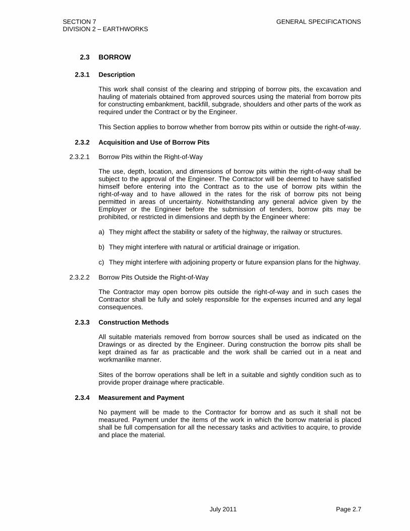
2.3.1 Description
This work shall consist of the clearing and stripping of borrow pits, the excavation and hauling of materials obtained from approved sources using the material from borrow pits for constructing embankment, backfill, subgrade, shoulders and other parts of the work as required under the Contract or by the Engineer. This Section applies to borrow whether from borrow pits within or outside the right-of-way.
2.3.2 Acquisition and Use of Borrow Pits
2.3.2.1 Borrow Pits within the Right-of-Way
The use, depth, location, and dimensions of borrow pits within the right-of-way shall be subject to the approval of the Engineer. The Contractor will be deemed to have satisfied himself before entering into the Contract as to the use of borrow pits within the right-of-way and to have allowed in the rates for the risk of borrow pits not being permitted in areas of uncertainty. Notwithstanding any general advice given by the Employer or the Engineer before the submission of tenders, borrow pits may be prohibited, or restricted in dimensions and depth by the Engineer where: a) They might affect the stability or safety of the highway, the railway or structures. b) They might interfere with natural or artificial drainage or irrigation. c) They might interfere with adjoining property or future expansion plans for the highway.
2.3.2.2 Borrow Pits Outside the Right-of-Way
The Contractor may open borrow pits outside the right-of-way and in such cases the Contractor shall be fully and solely responsible for the expenses incurred and any legal consequences.
2.3.3 Construction Methods
All suitable materials removed from borrow sources shall be used as indicated on the Drawings or as directed by the Engineer. During construction the borrow pits shall be kept drained as far as practicable and the work shall be carried out in a neat and workmanlike manner. Sites of the borrow operations shall be left in a suitable and sightly condition such as to provide proper drainage where practicable.
2.3.4 Measurement and Payment
No payment will be made to the Contractor for borrow and as such it shall not be measured. Payment under the items of the work in which the borrow material is placed shall be full compensation for all the necessary tasks and activities to acquire, to provide and place the material.

SECTION 7 GENERAL SPECIFICATIONS DIVISION 2 – EARTHWORKS
July 2011 Page 2.8
2.4 CHANNEL EXCAVATION
2.4.1 Description
This work shall consist of excavation for channels for discharging water from side ditches where shown on the Drawings, required in the Specifications or as directed by the Engineer. The work shall include the proper utilisation and hauling or disposal of all excavated materials, and constructing, shaping and finishing of all earthworks.
2.4.2 Materials
Excavated materials shall be classified as unsuitable and suitable soil. To be suitable as fill material the soil must not contain muck, roots, sods or other deleterious materials and must conform to the requirements of Section 2.6.2.
2.4.3 Construction Methods
2.4.3.1 Alignment and Levels
Channel work shall be constructed in a neat and workmanlike manner correct to alignments, levels, grades and cross sections required on the Drawings, in the Specifications or by the Engineer.
2.4.3.2 Excavation
Deepening and realignment of existing canals and channels shall be carried out in a way to allow free flow of the water. During excavation of new channels these shall as far as possible be kept drained. All suitable materials removed from the excavation shall be used as far as practicable in constructing the roadway.
2.4.3.3 Filling of Obsolete Channels
Any obsolete canals and channels within the embankment area shall be cleaned up and back filled with sand to obtain sufficient stability. When sand fill is at a level of 500 mm above water level, compaction shall be carried out as specified in Section 2.6.
2.4.3.4 Unsuitable Excavated Material
Excavated material from channel excavations classified as unsuitable as fill material by the Engineer shall be known as waste. The Contractor, shall stockpile, or place the material in a location approved by the Engineer.
2.4.3.5 Excess Suitable Excavated Material
Suitable material from channel excavation, which is in excess of that, required for construction of any part of the Works shall be the property of the Employer and shall be stockpiled on Site as instructed by the Engineer.
2.4.4 Measurement Payment for backfilling existing channels shall be in accordance with Section 2.6. Quantities of channel excavation in unsuitable material shall be measured in cubic metres determined by average end area methods computed from the original and final geometric cross sections of the authorised and completed excavation.

SECTION 7 GENERAL SPECIFICATIONS DIVISION 2 – EARTHWORKS
July 2011 Page 2.9
Excavation of channel in suitable material shall not be measured for direct payment. The cost shall be deemed to be included in the rates for the items of the Works in which the excavated material is placed. The exception to this is excess suitable material which is stockpiled on Site. Measured channel excavation shall include for the removal of any slides and cave-ins which occur in channels except where these have been caused by carelessness or the use of improper methods by the Contractor.
2.4.5 Payment
This work measured as provided above shall be paid for at the Contract unit price per cubic metre. The payment shall be full compensation for all excavation, for maintaining free flow in the channel where necessary and for all labour materials, tools, equipment and incidentals necessary to complete the work, including stockpiling or disposal off Site. Channel excavation of material which is suitable for embankment fill shall not be paid for separately but shall be paid for at the rate for fill from land as provided for in Section 2.6. Pay items shall be: 2/4/1 Channel Excavation in Unsuitable Material Cubic Metre 2/4/2 Channel Excavation in Suitable Material Cubic Metre including stockpiling on Site (applies to Excess Suitable Excavated Material only)

SECTION 7 GENERAL SPECIFICATIONS DIVISION 2 – EARTHWORKS
July 2011 Page 2.10
2.5 EXCAVATION AND BACKFILL FOR STRUCTURES
2.5.1 Description
This work shall consist of excavation in any material for the foundation of structures, other than for pipe culverts, not otherwise provided for in the Specifications; constructing and removing cofferdams, sheeting; pumping, dewatering and bailing; backfilling of completed structures with suitable material and disposal of excavated material. Pipes and manholes shall be excavated and backfilled in accordance with Sections 6.2 and 6.3. Filling of areas above the natural ground level or above the limits of road excavation or channel excavation is described in Section 2.6.
2.5.2 Materials
2.5.2.1 Foundation Fill Material
Material for foundation fill shall consist of suitably graded sand to one of the grading envelopes A to C of Section 2.8.2, gravel or stone as shown on the Drawings or as required by the Engineer, or concrete. Concrete for foundation fill shall conform to the general requirements of Section 5.1. Concrete to be placed under water shall conform to the requirements of Section 5.1.3.14. Concrete used as foundation fill in dry excavation shall be class 15.
2.5.2.2 Backfill Material
Backfill materials below top level of pile caps shall consist of sand with not more than 10% of material passing the 75 micron sieve, if not otherwise directed by the Engineer or stated on the Drawings. Backfill above top level of pile caps but outside embankment and road areas shall be excavated material if suitable and approved by the Engineer.
2.5.3 Construction Methods 2.5.3.1 Clearing
Prior to starting excavation operations in any area, all necessary clearing and grubbing shall have been performed.
2.5.3.2 Excavation
A) General The Contractor shall notify the Engineer sufficiently in advance of the beginning of any excavation so that cross section elevations and measurements may be taken of the undisturbed ground. The natural ground adjacent to the structure shall not be disturbed without permission of the Engineer. Trenches and foundation pits for structures and structure footings shall be excavated to the lines, grades and elevations shown on the Drawings or as directed by the Engineer. The elevations of the bottoms of footings shown on the Drawings are approximate only and the Engineer may order in writing such changes in the dimensions or elevations of footings as may be deemed necessary to secure a satisfactory foundation. Boulders, logs and other objectionable material encountered in excavation shall be removed. After each excavation is complete the Contractor shall notify the Engineer to that effect and no footings, bedding material or structure shall be placed until the

SECTION 7 GENERAL SPECIFICATIONS DIVISION 2 – EARTHWORKS
July 2011 Page 2.11
Engineer has approved the depth of excavation and the character of the foundation material. The foundation material shall be cleared of all loose material and cut to a firm surface, either level or stepped or serrated, as specified or shown on the Drawings or directed by the Engineer. B) Foundation Directly on the Ground When the footing is to rest on the ground and not on piles, special care shall be taken not to disturb the bottom of the excavation, and excavation to final grade shall be deferred until just before the footing is to be placed. When, in the opinion of the Engineer, the foundation material is soft or otherwise unsuitable, the Contractor shall remove the unsuitable material and insert foundation fill material or concrete as specified or shown on the Drawings or directed by the Engineer. If foundation fill material is required, it shall be placed and compacted in layers not more than 150 mm thick to the degree of compaction as specified in Section 2.6. C) Foundation on Piles When the ground between piles is too soft to support green foundation concrete, the Contractor shall submit his proposals for a bottom form to the Engineer for his approval. Extra excavation and foundation fill or concrete fill in such cases will not be paid for separately. If the bottom form is achieved by such strengthening of the ground, the Contractor shall, if requested, submit calculations showing that the pile cap will not be harmed during hardening due to differential settlements between the piles and the strengthened ground.
2.5.3.3 Disposal of Excavated Material
Excavated material classified as suitable by the Engineer shall generally be utilised as backfill or embankment fill. Surplus suitable material shall be stockpiled on Site as described in Section 2.2.3.4 of these Specifications. Excavated suitable material for use as backfill shall be deposited by the Contractor in spoil heaps at points convenient for re-handling of the material during the backfilling operation and approved by the Engineer. Excavated material classified as unsuitable as backfill by the Engineer shall be carried to waste as described in Section 2.2.3.3 of these Specifications. Excavated material shall be deposited in such places and in such a manner as not to cause damage to roads, services or property either within or outside the right-of-way and so as to cause no impediment to the drainage of the site or surrounding area. The location of spoil heaps shall be subject to the approval of the Engineer who may require that the reference lines and the traverse lines of any part of the structure be kept free of obstruction.
2.5.3.4 Cofferdams
A) The term “cofferdam” denotes any temporary or removable structure, constructed to hold the surrounding earth, water or both, out of the excavation, whether such structure is constructed of earth, timber, steel, concrete or any combination of these. The term includes earth dikes, timber cribs, sheet piling, removable steel shells and all bracing; and it shall be understood to include excavation enclosed by pumping wells and well points.
The cost of cofferdams is always to be included in the tender rates/prices for the
permanent work.

SECTION 7 GENERAL SPECIFICATIONS DIVISION 2 – EARTHWORKS
July 2011 Page 2.12
B) The term “caisson” denotes a permanent part of the substructure so constructed as to sink gradually into place as material is excavated within the area protected by its side walls. Where the term “well” is used it shall be taken to have the same meaning as “caisson”.
C) When no provision for caissons is shown on the Drawings, it shall be the intent of the
Contract that suitable cofferdams shall be provided for all excavations where cofferdams may be necessary in order to control water to preclude sliding and caving of the walls of the excavation.
D) The Contractor shall submit upon request, drawings showing his proposed method of
cofferdam and caisson construction. Approval of the drawings by the Engineer will not in any way relieve the Contractor of the responsibility for the adequacy of the design for strength and stability or for the safety of the people working therein.
E) The interior dimensions of cofferdams shall be such as to give sufficient clearance for
the construction and removal of any required forms and the inspection of the interior and to permit pumping.
F) If possible, cofferdams shall be so designed that no cross bracing shall be left in
place. If this is not possible, bracings left in place shall be of structural steel. The end of such structural members that would be exposed when the structure is completed shall be boxed back at least 50 mm behind the concrete face. The resulting holes shall be completely filled with concrete.
G) In general, sheet piling cofferdams shall extend well below the bottom of the footing
and shall be well braced and as watertight as possible. H) When foundation piles are to be driven inside a cofferdam and it is judged impossible
to de-water the cofferdam before placing a concrete seal, the excavation may be extended below the designed level to a depth sufficient to allow for swell of the material during pile driving operations. Any material that rises to a level above the design level shall be removed.
I) Where it is possible to de-water the cofferdam, the foundation material shall be
removed to exact grade after the foundation piles are driven. J) Backfilling in a foundation to compensate for excavation, which has been extended
below the required grade, shall be at the expense of the Contractor. Backfilling shall be with concrete or foundation fill material as indicated on the Drawings, or as directed by the Engineer.
If no material is indicated, backfilling shall be concrete of the same kind as required
for the structure to be constructed in the excavation. Unless otherwise permitted no excavation shall be made outside of caissons or cribs or cofferdams or sheet piling and the natural streambed adjacent to the structure shall not be disturbed without permission from the Engineer.
If any excavation or dredging is made at the site of the structure before caissons, cribs, or cofferdams are in place, the Contractor shall after the foundation is in place, backfill all such excavation to the original ground surface or stream bed with material satisfactory to the Engineer.
Material deposited within the stream area from foundations or other excavations or
from the filling of cofferdams shall be removed and the stream area freed from obstruction.
K) Caissons and cofferdams, which have tilted or moved laterally during construction,
shall be corrected as necessary at the expense of the Contractor.

SECTION 7 GENERAL SPECIFICATIONS DIVISION 2 – EARTHWORKS
July 2011 Page 2.13
L) Unless otherwise provided cofferdams shall be removed after the completion of the sub-structure. The removal shall be effected in such a manner as not to disturb or mar the finished work. The Engineer may order the Contractor to leave any part or the whole of the cofferdam in place.
M) When conditions which, in the opinion of the Engineer, render it impossible to
de-water the foundation before placing the footing are encountered, the Engineer may require the construction of a concrete foundation or seal of such dimensions as he may consider necessary, and of such thickness as to resist any possible uplift. The concrete for such seal shall be placed as shown on the Drawings or required by the Engineer. The foundation shall then be de-watered and the footing placed. When weighted cribs are used and the weight is used to overcome partially the hydrostatic pressure acting against the bottom of the foundation seal, special anchorages such as dowels or keys shall be provided to transfer the entire weight of the crib to the foundation seal. When a foundation seal is placed under water the cofferdam shall be vented at low water as directed.
Cofferdams shall be constructed so as to protect newly cast concrete from sudden
rising of the water and to prevent damage to the foundation by erosion.
2.5.3.5 Pumping and Bailing
Pumping and bailing from the interior of any foundation enclosure shall be done in such a manner as to preclude the possibility of the movement of water through or alongside any concrete being placed. No pumping or bailing will be permitted during the placing of concrete and for a period of a least 24 hours thereafter unless it is done from a suitable pump separated from the concrete work by a watertight wall or from well points. Excavations shall be as dry as possible prior to and during placing concrete. Placing concrete under water will only be permitted if indicated on the Drawings or approved by the Engineer.
2.5.3.6 Backfilling
All spaces excavated under these Specifications and not occupied by the permanent structure shall be backfilled. Backfilled material shall fully comply with this Specification and adequate provision shall be made for drainage. No backfilling shall commence until permission has been given by the Engineer. Backfill under top level of pile caps shall always be made with compacted sand fill free from chemical contamination. Over top level of the pile cap but outside embankment and road areas, the backfill shall be excavated material if suitable and free from chemical contamination, and approved by the Engineer. If the excavated material is not suitable, the Engineer may order sand filling. Backfill within the embankment and road areas shall be made in accordance with Section 2.6 of these Specifications. Special care shall be taken to prevent any unduly high pressure against the structures. In placing backfill and embankment, the material shall be placed insofar as possible to approximately the same height on both sides of the structure at the same time. If conditions require backfilling appreciably higher on one side, the additional material on the higher side shall not be placed until permission is given by the Engineer that the structure has enough strength to withstand any pressure created. Jetting of fill or other hydraulic methods involving, or likely to involve, liquid or semi-liquid pressure is prohibited. Backfill and embankment fill shall not be placed behind the walls of bridges or box culverts until the top slab has been placed for at least three days.

SECTION 7 GENERAL SPECIFICATIONS DIVISION 2 – EARTHWORKS
July 2011 Page 2.14
The placing of embankment and the benching of slopes shall continue in such a manner that at all times there will be a horizontal berm of thoroughly compacted material for a distance at least equal to the height of the abutment or wall to be backfilled.
2.5.4 Measurement
The volume of excavation and backfill shall be measured in cubic metres of excavated undisturbed material. The quantity of excavation for structures to be measured for payment shall include excavation for all structures except pipe culverts, which will be in accordance with Section 6.2. The measured volume shall be the excavation plan outline, bounded on the bottom by the plane of the underside of the brick flat soling to the blinding concrete under the reinforced concrete footing and on the top by the surface of the existing ground and on the sides by vertical planes of the footings. Backfilling with previously excavated material shall not be measured or paid for separately but shall be deemed included in the rate for excavation. Backfill with concrete or sand where directed by the Engineer including concrete seals shall be measured separately as the volume within the plan outline and top and bottom surfaces. Concrete or sand placed to backfill excavation beyond the excavation required will not be measured for payment. The plan outline referred to is the excavation plan outline as defined above. If sand fill is ordered over top level of pile cap, the fill shall be the specified filling volume measured on the Drawings up to profiles agreed upon in writing by the Engineer. In the case of structures for which a lump sum price is called for, the volume of excavation as stated above for the work as shown on the Contract Drawings, shall be subtracted from the volume measured as above, and the price to be paid or deducted shall be based on the measured increase or reduction of the excavation shown on the Drawings. Removal of slides, cave-ins, silting or filling shall not be measured nor paid for.
2.5.5 Payment
This work measured as provided in Section 2.5.4 shall be paid for at the Contract unit prices per cubic metre for each particular item. The payment shall be full compensation for all excavation, stockpiling, backfilling and disposal including compaction; constructing and removing all cofferdams; all dewatering, pumping and bailing; and for furnishing all materials, labour, equipment, tools, sheeting, bracing, cofferdams, pumps, and incidentals necessary to complete the work. Should it be necessary, in the opinion of the Engineer, to lower the footings to an elevation below the level shown on the Drawings, payment for the “Excavation and Backfill for Structures” required below plan level down to and including an elevation 1.5 metres below plan level for any individual footing will be made at a unit price equal to 115% of the Contract unit tender price. Payment for the excavation from an elevation greater than 1.5 metres below plan level down to and including an elevation 3 metres below plan level will be made at a unit price equal to 125% of the Contract unit tender price for “Excavation and Backfill for Structures”. No additional extra compensation will be allowed for any required cofferdam adjustments made necessary by such lowering of footings. In case where the extra depth required for any footing or footings exceeds 3 metres, a supplementary agreement shall be made covering the quantities removed from depths in excess of 3 metres below plan grade.

SECTION 7 GENERAL SPECIFICATIONS DIVISION 2 – EARTHWORKS
July 2011 Page 2.15
Payment for backfilling shall be included in the pay item for “Excavation and Backfill for Structures” except for sand backfill and concrete backfill. These backfill types shall be measured as provided in Section 2.5.4 and paid for at the concerned Contract unit prices, but no compensation in the pay item “Excavation and Backfill for Structures” shall be made for less backfilling with excavated material or more surplus to waste. All payment for the backfilling and compaction of those areas which were removed, as structural excavation shall be included in the appropriate unit rates below. Filling or backfilling of areas above the natural ground level or above the limits of road excavation or channel excavation section shall be paid for under Section 2.6. Cofferdams for structures without excavation, for example for pile caps over water shall be deemed to be included in the unit prices for the concerned pile cap. Pay items shall be: 2/5/1 Excavation and Backfill for Structures Cubic Metre 2/5/2 Concrete Backfill for Structures Cubic Metre 2/5/3 Sand Backfill for Structures Cubic Metre

SECTION 7 GENERAL SPECIFICATIONS DIVISION 2 – EARTHWORKS
July 2011 Page 2.16
2.6 EMBANKMENT
2.6.1 Description
This work shall consist of the construction of embankment and fill by furnishing, placing, compacting and shaping suitable material of acceptable quality obtained from approved sources in accordance with these Specifications and to the lines, levels, grades, dimensions and cross sections shown on the Drawings or as required by the Engineer.
2.6.2 Materials
All fill materials shall be free from roots, sods or other deleterious material. Materials for embankments shall be from sources which the Contractor shall propose and which shall be approved by the Engineer. Approval shall normally be given to the use of material which, when compacted to 98% of maximum dry density determined in accordance with STP 4.3 has a 4 day soaked CBR value of not less than 4%.
• Liquid limit of soil fraction passing 0.425 mm sieve not to exceed 50% (STP 3.2) • Plasticity index of soil fraction passing 0.425 mm sieve not to exceed 25% (STP 3.2)
2.6.3 Construction Methods
2.6.3.1 Preparation of Foundations for Embankment
Prior to placing any embankment upon any area, all clearing and grubbing operations shall have been completed in accordance with Section 2.1 and excavation under carriageways shall be carried out in accordance with Section 2.2. The original ground surface shall be disturbed as little as possible except for levelling of dikes, terraces and obsolete ditches. Existing ditches etc., shall be closed at the embankment as described in Section 2.1.3.5. Embankments in swamps or water shall be constructed as indicated on the Drawings and as described in these Specifications. The Contractor shall, when ordered by the Engineer, excavate or displace swamp ground (Section 2.2.3.5) and backfill with river or beach sand unless otherwise directed by the Engineer.
2.6.3.2 Placing Embankment
A) General Except as otherwise required by the Drawings, all embankments shall be constructed in layers approximately parallel to the finished grade of the roadbed. During construction of embankment, a smooth grade having an adequate crown shall be maintained at all times to provide drainage. The placing of fill shall be carried out in successive layers for the full width of fill as shown on the Drawings with allowance being made for the placement of topsoil if applicable and in such lengths as are suited to the watering and compaction methods utilised. Each layer shall not exceed 150 mm in thickness on completion of compaction. The completed embankment shall have the required form, cross-section, grade and levels as detailed on the drawings or as directed by the Engineer with a surface tolerance of ±25mm from the specified levels. Embankment fill placed adjacent to structures shall be in accordance with Section 2.5.3.6.

SECTION 7 GENERAL SPECIFICATIONS DIVISION 2 – EARTHWORKS
July 2011 Page 2.17
B) Placing Embankment over Swampy Ground Where new embankment will overlay existing canals, ditches, ponds or other waterways, these shall be filled in exclusively with sand in accordance with Section 2.4.3.3. Prior to filling, cofferdams shall be made to allow pumping, and the bed shall be left to dry until approved by the Engineer for filling. The Works shall be performed in such a manner and at such times as to avoid interruption of or interference with the free flow of water in the canals. Full compensation for conforming to these requirements shall be considered included in other rates within the Contract items, and no additional payment will be made. C) Widening of Existing Embankment Where embankment fill is being carried out to widen an existing embankment the new fill material shall be fully keyed into the old embankment by means of benching which shall be in steps each not less than 300 mm high and 600 mm wide. Steps shall be cut in advance of the filling. Material cut in benches may be used as fill if found to be suitable.
2.6.3.3 Compaction of Embankment.
The moisture content of the fill materials before compaction shall be within ±2% of the optimum moisture content as determined in accordance with STP 4.3(Standard Compaction). The achieved dry density of the embankment after compaction shall not be less than 98% of maximum dry density determined earlier in accordance with STP 4.3. One density test for each 1,000 square metres of a completed layer will be carried out according to STP 6.2, unless otherwise directed by the Engineer. If test results show that the density is less than the required density, the Contractor shall carry out further compaction to obtain at least the required density. The compacted layer shall be approved by the Engineer before the Contractor can commence a new layer. In addition to the density test, one Dynamic Cone Penetrometer (DCP) test shall be carried out for each 500 sqm of a completed layer; the rate of penetration from the test should not exceed 38 mm/ blow. When necessary, each layer, before being compacted, shall be mixed with dry material or otherwise processed to bring the moisture content sufficiently close to optimum to make possible its compaction to the required density. The material shall be so worked as to have a uniform moisture content through the entire layer. Each layer of material shall be compacted uniformly by use of adequate and appropriate compaction equipment. The compaction shall be done in a longitudinal direction along the embankment and shall generally begin at the outer edges and progress toward the centre in such a manner that each section receives equal compactive effort. Hauling equipment shall be operated over the full width of each layer in so far as practicable.

SECTION 7 GENERAL SPECIFICATIONS DIVISION 2 – EARTHWORKS
July 2011 Page 2.18
2.6.4 Measurement
Embankment shall be measured in cubic metres based on cross sections of accepted embankment constructed and completed in accordance with the Specifications, to the lines, levels and grades required or as directed by the Engineer. The cross section to be used will be the area bound by the subgrade (below improved subgrade or sub-base) the side slopes or edge limits and the original ground line or the level after excavation of unsuitable material with the net volume being calculated by the End area method. A deduction of volume will occur when topsoil is placed in accordance with Section 6.6 of this Specification. No allowance will be made for material cut in benching operations. The final volume of embankment fill shall not include the voids for bridges and box-culverts, but the voids for pipes, manholes, catch basins and the like will however not be deducted. Sand backfill to swampy ground shall be measured in cubic metres based on the net volumes backfilled as directed by the Engineer.
2.6.5 Payment
This work measured as provided above shall be paid for at the Contract unit prices per cubic metre. Payment shall be full compensation for performing the work, furnishing the materials and providing all labour, equipment, tools and incidentals necessary to complete the work. Partial payment may be made on measured volumes of required embankment fill actually executed. The Engineer will set terms for deduction in this quantity to compensate for work not fully completed.
Pay items shall be:
2/6/1(a) Embankment Fill from Excavation on Site Cubic Metre 2/6/1(b) Embankment Fill from Excavation in Borrow Pit within the Right-of-Way Cubic Metre 2/6/2 Embankment Fill from Borrow Pit in Contractor’s Arranged Land Cubic Metre
2/6/3 Sand Backfill to Swamp Cubic Metre

SECTION 7 GENERAL SPECIFICATIONS DIVISION 2 – EARTHWORKS
July 2011 Page 2.19
2.7 PREPARATION OF SUBGRADE
2.7.1 Description
This work shall consist of the preparation of subgrade in embankment, or in cut by removing, scarifying, watering, compacting and shaping existing or previously placed material in accordance with these Specifications and to the lines, levels, grades, dimensions and cross sections shown on the Drawings or as required by the Engineer.
2.7.2 Materials
All subgrade material shall be from sources, which the contractor shall propose and which shall be approved by the Engineer. The material shall be free from roots, sods or other deleterious material and when compacted to 95% of maximum dry density determined in accordance with STP 4.4 shall have a 4 day soaked CBR value of not less than 6%. Subgrade material shall satisfy the following criteria: • Liquid limit of soil fraction passing 0.425 mm sieve not to exceed 50% (STP 3.2) • Plasticity index of soil fraction passing 0.425 mm sieve not to exceed 15% (STP 3.2) Any subgrade material in cut or existing old embankment, which is found to be unsuitable, shall be removed and replaced as directed by the Engineer.
2.7.3 Construction Methods
The subgrade shall be prepared over the full width of the embankment including shoulders. Part width working may be allowed with the prior written approval of the Engineer. The subgrade shall be prepared in lengths of not less than 100 metres at any one time, unless otherwise approved by the Engineer. Where the subgrade is in embankment, the subgrade layers to the required depth shall be compacted to achieve dry density not be less than 95% of maximum dry density (MDD) determined earlier in accordance with Modified Proctor Test (STP 4.4). In the case of road sections in cut or in case of full reconstruction of pavements, where the existing subgrade does not meet the above compaction criteria upto a depth of 300 mm, the material in the upper layer will be first removed and stacked separately. The bottom layer shall be scarified until the soil is fully loosened; any lumps or clods shall be removed or broken to pass 50 mm sieve. The layer shall be brought to optimum moisture content (OMC) and then compacted so as to achieve the minimum compaction level as given above, and minimum CBR of 6%. Any unsuitable material occurring within the layers shall be removed and replaced by approved materials. The second layer of subgrade shall be laid after testing and approval the first layer and compacted to similar specifications. The moisture content of the sub-grade material before compaction shall be within ±2% of the predetermined optimum moisture content established in accordance with STP 4.3 (Standard Compaction). The achieved dry density after compaction of the subgrade layer shall not be less than 98% of maximum dry density as determined in accordance with STP 4.3.

SECTION 7 GENERAL SPECIFICATIONS DIVISION 2 – EARTHWORKS
July 2011 Page 2.20
When necessary, each layer, before being compacted, shall be allowed to dry or be watered to bring the moisture content to within ±2% of optimum to make possible its compaction to the required dry density. The material shall be so worked as to have a uniform moisture content through the entire layer. The subgrade material shall be compacted uniformly by use of adequate and appropriate compaction equipment. The compaction shall be done in a longitudinal direction along the embankment and shall generally begin at the outer edges and progress toward the centre in such a manner that each section receives equal compactive effort. Samples to determine the compaction shall be taken regularly with a set of three samples for each 1,000 square metres of finished layer or as decided by the Engineer will be carried out according to STP 6.2. If the test results show that the density is less than the required dry density, the Contractor shall carry out further compaction to obtain at least the required dry density. In addition to the density test, one Dynamic Cone Penetrometer (DCP) test shall be carried out for each 500 sqm of a completed layer; the rate of penetration from the test should not exceed 28 mm/ blow. The compacted subgrade layer shall be approved by the Engineer before the Contractor can commence a new layer. The surface of the finished subgrade shall be neat and workmanlike and have the required form, super elevation, levels, grades and cross section. The finished surface shall be constructed with a tolerance of 20 mm above or below the specified levels at any point.
2.7.4 Measurement
Subgrade preparation shall be measured in square metres based on the surface area of compacted and accepted subgrade actually completed in accordance with the Specifications, to the lines, levels, grades and cross sections required as directed by the Engineer. No allowance will be made for overlapping of areas due to half width working. No differentiation will be made between subgrade compaction in cut or in fill.
2.7.5 Payment
This work measured as provided above shall be paid for at the Contract unit prices per square metre. Payment shall be full compensation for performing the work and providing all labour, equipment, tools and incidentals necessary to complete the work. The rates shall not include the cost of furnishing the subgrade materials which, if not existing, shall be included in the quantity for fill material as provided for in Section 2.6. Pay item shall be:
2/7/1 Preparation of subgrade 300 mm Depth Square Metre
2/7/2 Preparation of subgrade 450 mm Depth Metre Square Metre

SECTION 7 GENERAL SPECIFICATIONS DIVISION 2 – EARTHWORKS
July 2011 Page 2.21
2.8 IMPROVED SUBGRADE
2.8.1 Description
This work shall consist of furnishing, placing and compacting improved subgrade material on a prepared and accepted subgrade in accordance with these Specifications, and to the lines, levels, grades, dimensions and cross sections shown on the Drawings, or as required by the Engineer.
2.8.2 Materials
Material shall be a natural or artificial mixture of sand or other mineral aggregates, free from vegetable matter, soft particles, clay and excess quantities of silt. Grading: The grading (washed method) shall conform to one of the grading envelopes A to C in Table 2.8-1. If the material meeting these grading is not locally available then grading-D may be used with the permission of Engineer. Material with the grading-E shall not be allowed to be used under this item. Table 2.8-1
A B C D E Nominal fineness modulus
Not lessthan 2.8
1.5 - 2.8
1.0 - 1.5
0.8 - 1.0
0.5 - 0.8
Sieve size
(mm)
% passing by weight
10 100 100 100 100 100
5.0 90 – 95 95 - 100 100 100 100
2.4 70 – 90 90 - 100 100 100 100
1.2 45 – 70 70 - 95 95 - 100 100 100
0.6 25 – 45 40 - 80 85 - 100 95 - 100 100
0.3 10 – 20 10 - 50 50 - 80 70 - 90 80 - 95
0.15 0 – 2 0 - 20 5 - 25 15 - 40 30 - 60
Gradings outside the above limits may in certain circumstances be approved by the Engineer. Such permission shall be in writing.
b) Plasticity. The portion of material passing the 0.425 mm sieve shall be non-plastic,
when tested in accordance with test procedure STP 3.2.” c) CBR. The material shall have a soaked CBR value not less than 8% when compacted
to 95% of maximum dry density as determined by STP 4.5 (Vibrating Hammer compaction).
d) The material shall be free draining. Suitable measures shall be taken for protecting
the material from erosion, with necessary arrangement to drain out the water from subgrade.

SECTION 7 GENERAL SPECIFICATIONS DIVISION 2 – EARTHWORKS
July 2011 Page 2.22
2.8.3 Construction Methods
2.8.3.1 Preparation of Subgrade
The subgrade shall be shaped and compacted in conformity with the provisions of Section 2.7 and completed along with all subgrade drainage ahead of the placing of the improved subgrade material. Notwithstanding any earlier approval of subgrade, any damage to or deterioration of subgrade shall be made good before the improved subgrade is laid. Preparation of the subgrade shall be carried out, unless otherwise agreed by the Engineer, immediately prior to laying the improved subgrade.
2.8.3.2 Spreading
Improved subgrade shall be spread in layers, with uncompacted thickness up to 200 mm, subject to the approval of the Engineer, and the layers shall be as nearly equal in thickness as possible. Where the material for shoulders is the same as that used for the improved subgrade course, the material shall be placed for the full width of the roadbed and the shoulders simultaneously. Where the shoulders are not of the same material as the improved subgrade course, then the improved subgrade shall be spread to give the required compacted depth and the edge detail shown on the Drawings. When the improved subgrade course is spread contiguous to concrete kerbs or gutters, extreme care shall be exercised not to damage the kerbs or gutters. Any damage of kerbs or gutters resulting from carelessness or negligent construction methods by the Contractor shall warrant the removal and replacement of said kerbs or gutters at the Contractor’s sole expense.
2.8.3.3 Sprinkling, Rolling and Compacting
Each layer shall be compacted to at least 95% of the maximum dry density as determined by STP 4.5 (Vibrating Hammer). 3 No. in situ density tests in accordance with STP 6.2 shall be taken from each 1,000 square metres of compacted improved subgrade, or as directed by the Engineer. If the achieved density is less than the minimum required, the Contractor shall carry out further compaction. When commencing work on the improved subgrade the Contractor shall carry out a field compaction trial to determine the optimum moisture content and the required number of passes of his particular compaction equipment to comply with the Specification. This method will be approved by the Engineer and shall be used for all subsequent compaction of improved subgrade material. Such agreement will not however relieve the Contractor of his responsibility and in the event that test results later show that the specified compaction is not being achieved all improved subgrade work shall cease and not be resumed until a fresh trial has been undertaken and a revised compaction method approved by the Engineer. In order to ensure uniform bearing capacity at the finished improved subgrade level, CBR tests shall be carried out as directed by the Engineer. The CBR shall be such that the laboratory value obtained in accordance with STP 5.1, at the specified compaction and after 4 days soaking, shall exceed 8%. In areas where these requirements are not met, correction shall be made by such measures as the Engineer deems necessary. Immediately after each layer has been spread and shaped satisfactorily, each layer shall be thoroughly compacted with suitable and adequate compaction equipment approved by

SECTION 7 GENERAL SPECIFICATIONS DIVISION 2 – EARTHWORKS
July 2011 Page 2.23
the Engineer. Rolling operations shall begin from the outer edge of roadbed toward the centre, gradually in a longitudinal direction; except on super-elevated curves, where rolling shall begin at the low side and progress towards the high side. Improved subgrade material which does not contain sufficient moisture to be compacted in accordance with the requirements of this Section shall be watered by methods approved by the Engineer at the Contractor’s own expense. Improved subgrade material containing excess moisture shall be dried prior to or during compaction by methods approved by the Engineer, at the expense of the Contractor. The finished improved subgrade shall follow the required grades and cross sections and at any point shall not vary more than 20 mm above or below the specified level. The thickness of the finished improved subgrade shall be: -not thinner than 20 mm less than the required thickness at any point -overall not less than the required thickness when five thickness measurements are averaged in any 100 metres of road. Improved subgrade which does not conform to the above requirements shall be reworked, watered and thoroughly re-compacted to conform.
2.8.4 Measurement
Improved subgrade as described in this section shall be measured by the cubic metres of material compacted in place and accepted. Measurement shall be based on the average width and thickness of the improved subgrade shown on the Drawings and actual length measured horizontally along the centreline of the surface of the road.
2.8.5 Payment
This work measured as provided above shall be paid for at the Contract unit rate per cubic metre for improved subgrade. The payment shall be full compensation for furnishing all materials, hauling, placing, compacting, sprinkling, finishing and shaping, and for all labour, equipment, tools and other incidentals necessary to complete the work specified. Pay item shall be: 2/8/1 Improved Subgrade Cubic Metre

SECTION 7 GENERAL SPECIFICATIONS DIVISION 2 – EARTHWORKS
July 2011 Page 2.24
2.9 REMOVAL OF EXISTING STRUCTURES
2.9.1 Description
This work shall consist of the satisfactory removal and salvage or disposal, wholly or in part, of existing bridges, structures, substructures, buildings, culverts etc., within the right-of-way as indicated in the Contract Documents or as required by the Engineer. The Employer will generally arrange for all structures within the right-of-way, which are not the property of the Employer to be removed by the respective owners prior to the Contractor commencing work on site. Existing structures which are the property of the Employer and which are in the vicinity of a proposed roadway shall be dismantled or demolished by the Contractor to a level one metre lower than the proposed road surface elevation. For areas of the Site that will be used for purposes other than roadways, existing structures shall be dismantled or demolished to a level lower than the lowest elevation of the finished ground level, as indicated on the Drawings or directed by the Engineer.
2.9.2 Materials Obtained from Dismantling
The materials in the existing structures may include but are not restricted to structural steel, reinforced concrete materials, or stone/brick masonry materials, in any combination. The concrete materials, stone/brick masonry materials obtainable from dismantling of structure shall be taken to stock-piles by the Contractor for their possible use in the works when so approved by the Engineer. The materials salvaged from dismantling may not in itself comply fully with specifications for intended use in the permanent works. The salvaged material shall be first sorted out as directed. The materials, which may be used directly in permanent works, shall be stockpiled separately from those that require processing for reuse. The materials selected for processing should be of such quality as will meet the specifications after breaking, screening and / or mixing with better quality materials if necessary. Acceptability of the materials (after processing as the case may be) shall be determined by the Engineer and only such materials that fully satisfy the specifications in all respects shall be permitted for incorporation in the permanent works.
Structural/reinforcing steel obtained from dismantling of the existing structures is not considered suitable for use in the permanent works. This will be the property of the Contractor; it will not be reused for the permanent Works, and shifted/disposed of from the site with intimation to the Engineer. Structures or portions thereof which are specified in the contract for re-erection shall be stored in separate piles in a location agreed by the Engineer.
The Contractor shall comply with all laws, ordinances, building regulations etc as prevailing in Bangladesh.
2.9.3 Backfilling after Dismantling of Structures
As directed by the Engineer, holes and depressions caused by dismantling operations shall be backfilled with excavated or other approved materials and thoroughly compacted in line with surrounding areas. The backfilling required for restoring the ground after dismantling of structures shall not be paid separately as the cost shall be deemed to be included in the rate for dismantling structures.
2.9.4 Measurement

SECTION 7 GENERAL SPECIFICATIONS DIVISION 2 – EARTHWORKS
July 2011 Page 2.25
The dismantling or rehabilitation, disposal of the material and the backfilling after dismantling of structures shall be measured as a Lump Sum per structure.
2.9.5 Payment
The Lump Sum (LS) amounts rates for the various items of dismantling or rehabilitation shall be the full compensation for carrying out the required operations including excavation backfilling and shaping and providing all labour, materials, tools, equipment, safeguards and incidentals necessary to complete the work for each individual structure. These will also include for handling, sorting out, salvaging, and stock piling usable materials. All materials from existing structures, which are suitable for use in the road pavement, shall be stockpiled in a manner approved by the Engineer. The rate per cubic metre inserted by the Contractor against pay item 2/9/3 shall be deducted from payments due to the Contractor. Pay item shall be: 2/9/1 Dismantling existing structure (Box
Culvert/Pipe Culvert/Bridge) including disposal of spoil and backfilling (Individual Structure to be stated in Bill of Quantities).
Lump Sum
2/9/2 Dismantling portions of existing structure including Stockpiling of materials (Individual Structure to be stated in Bill of Quantities)
Lump Sum
2/9/3(a) Deduction of the Value of Recovered Materials (Except Reinforcing steel) from Structures
Cubic Metre
2/9/3(b) Deduction of the Value of Recovered Materials (reinforcing Steel) from Structures
Tonnes

SECTION 7 GENERAL SPECIFICATIONS DIVISION 2 – EARTHWORKS
July 2011 Page 2.26
2.10 CONSTRUCTION OF EARTHEN SHOULDERS
2.10.1 Description
This work shall consist of the construction of shoulders to the road pavement by furnishing, placing, compacting and shaping suitable material of acceptable quality obtained from approved sources in accordance with these Specifications and to the lines, levels, grades, dimensions and cross sections shown on the Drawings or as required by the Engineer.
2.10.2 Materials
All shoulder materials shall be free from roots, sods or other deleterious material. Materials for shoulders shall be from sources, which the Contractor shall propose and which shall be approved by the Engineer. Approval shall not normally be given to the use of material from borrow areas which, when compacted to 98% of maximum dry density in accordance with STP 4.3, has a 4 day soaked CBR value of less than 8%. Shoulder materials shall conform to the following requirements. • Liquid limit of soil fraction passing 0.425 mm sieve not to exceed 40% (STP 3.2) • Plasticity index of soil fraction passing 0.425 mm sieve to be greater than 7% but not
to exceed 15% (STP 3.2)
2.10.3 Construction Methods
2.10.3.1 Preparation
Prior to placing any shoulder fill, all subgrade preparation and subgrade drainage work shall be complete.
2.10.3.2 Placing
Except as otherwise required by the Drawings, all shoulders shall be constructed in layers approximately parallel to the finished grade of the roadbed. The layers shall not exceed 150 mm in thickness on completion of compaction. Attention is drawn to the requirements for shoulders to be constructed in stages with the road pavement layers. The finished surface of the soft shoulder shall have a tolerance of ±20mm from the specified level for the full width, except that where it adjoins a hard shoulder then the level at this point must be equal or lower than the finished level of the approved hard shoulder.
2.10.3.3 Compaction of Shoulders
Each layer being compacted, shall be within ±2% of the optimum moisture content to ensure its compaction to the required density and shall be worked to have a uniform moisture content through the entire layer. The achieved dry density after compaction shall not be less than 98% of the maximum dry density as determined in accordance with STP 4.3. Samples to determine the compaction shall be taken regularly, with one sample for each 500 square metres of finished layer, or as directed by the Engineer. Such density tests will be carried out according to STP 6.2. If test results show that the achieved dry density is less than the minimum required, the Contractor shall carry out further compaction. Each compacted layer shall be approved by the Engineer before the Contractor can commence a new layer.

SECTION 7 GENERAL SPECIFICATIONS DIVISION 2 – EARTHWORKS
July 2011 Page 2.27
2.10.4 Measurement
Shoulders shall be measured in cubic metres based on cross sections compacted and accepted in place. The volume to be measured will be the net volume of required and accepted shoulder, constructed and completed in accordance with the Specifications, to the lines, levels, grades and cross sections required or as directed by the Engineer.
2.10.5 Payment
This work measured as provided above shall be paid for at the Contract unit prices per cubic metre. Payment shall be full compensation for performing the work, furnishing the materials and providing all labour, equipment, tools and incidentals necessary to complete the work. Pay item shall be: 2/10/1 Construction of Soil Earthen Shoulders Cubic Metre

SECTION 7 GENERAL SPECIFICATIONS DIVISION 2 – EARTHWORKS
July 2011 Page 2.28
2.11 CONSTRUCTION OF HARD SHOULDERS
2.11.1 Description
This work shall consist of the construction of hard shoulders to the road pavement by furnishing, placing, compacting and shaping suitable material of acceptable quality obtained from approved sources in accordance with these Specifications and to the lines, levels, grades, dimensions and cross sections shown on the Drawings or as required by the Engineer.
2.11.2 Materials
The materials for hard shoulder shall meet the requirements for aggregate base type II provided for in Section 3.3.2
2.11.3 Construction Methods
2.11.3.1 Preparation of Sub-base
The sub-base shall be shaped and compacted in conformity with the provisions of Section 3.2 to the correct moisture content, and be completed for at least 100 metres ahead of the placing of the hard shoulder material, unless otherwise approved by the Engineer.
2.11.3.2 Spreading Hard Shoulder
The aggregate and sand shall be mixed thoroughly to obtain a homogenous mix complying with either grading A or B of Section 3.3.2. Water shall be added during mixing to keep the mixed material moist so as to prevent segregation during transportation. The mixed hard shoulder material, which should be at or near optimum moisture content shall be spread in two layers of nearly equal thickness so that the compacted thickness shall conform to that shown on the Drawings or as directed by the Engineer. All areas of segregation shall be corrected, or removed and replaced with well graded material. Where the material for hard shoulders is the same as that used for the base course, the material shall be evenly spread in layers, as herein specified, for the full width of the roadbed and the base course and the shoulders should be constructed simultaneously. At the edge of the hard shoulders the hard shoulder material shall be spread to give the required compacted depth and the edge detail shown on the Drawings.
2.11.3.3 Sprinkling, Rolling and Compacting
Immediately after each layer has been spread and shaped satisfactorily, each layer shall be thoroughly compacted with suitable and adequate compaction equipment approved by the Engineer. Hard shoulder material, which does not contain sufficient moisture to be compacted in accordance with the requirements of this Section, shall be sprinkled with water. The Contractor shall supply the necessary water at his own expense. Hard shoulder material containing excess moisture shall be dried prior to or during compaction. Drying of wet material shall be performed by methods approved by the Engineer, at the expense of the Contractor. Each layer shall be compacted to at least 98% of the maximum dry density as determined by STP 4.5 (Vibrating Hammer). Density of the compacted hard shoulder shall be

SECTION 7 GENERAL SPECIFICATIONS DIVISION 2 – EARTHWORKS
July 2011 Page 2.29
determined in accordance with STP 6.2 (150 mm or 200 mm diameter), with at least one test being made for each 200 linear metres of hard shoulder. The final shaping and rolling of the soft shoulder to the full width shall be made after the hard shoulder is completed.
2.11.3.4 Surface Tolerance
The finished surface of the hard shoulder shall follow the required grades, levels and cross-sections and shall not vary from the specified level by more than ±10mm. The finished surface shall also not deviate by more than 10mm from a 3m long straight edge laid perpendicular and parallel to the road centre-line. Any areas having irregularities greater than 10 mm, shall be corrected by loosening, adding or removing material, reshaping and re-compacting. The minimum thickness at any single point shall be not less than the required thickness less 10 mm. The hard shoulder shall also have an average thickness not less than the required thickness when five thickness measurements are averaged in any 100m length of completed shoulder. The Contractor shall carry out at his own expense, the reconstruction of areas of hard shoulder, which are too thin or too variable in thickness to meet this requirement.
2.11.4 Measurement
This item shall be measured as the number of cubic metres of material complete in place and accepted. Measurements shall be based on the cross section of the hard shoulder shown on the Drawings and the actual length measured on the surface of the road.
2.11.5 Payment
This work measured as provided above shall be paid for at the Contract unit rates per cubic metre for hard shoulder. The payment shall be full compensation for furnishing all materials, hauling, placing, compacting, sprinkling, finishing and shaping and for all labour, equipment, tools and other incidentals necessary to complete the work. Hard shoulder shall be paid for at the Contract unit rates irrespective of the sources of material used. All costs of excavating existing pavement or savings to the Contractor from re-using materials excavated from existing pavements in section 2.2 should be included under this item. Pay items shall be: 2/11/1 Construction of Hard Shoulder Cubic Metre

SECTION 7 GENERAL SPECIFICATIONS DIVISION 2 – EARTHWORKS
July 2011 Page 2.30
2.12 SUBGRADE DRAINS
2.12.1 Description
This work shall consist of excavating, furnishing material, backfilling and finishing drains to the prepared and accepted subgrade in accordance with these specifications and the dimensions and cross sections shown on the drawings, or as required by the Engineer.
2.12.2 Materials
The material for backfilling of subgrade drains shall be clean free draining sand and gravel, free from any vegetable matter, soft particles, silt or clay.
The grading requirement of the drain backfill material shall conform to that shown in Table 2.12-1 below:
Table 2.12-1
Sieve size % passing by weight
Min - Max 10 mm 5 mm
2.4 mm 1.2 mm 0.6 mm 0.3 mm
0.15 mm 0.075 mm
100 80-100 65-95 50-80 25-50 10-20 0-10 0-2
The separator material shall consist of suitable woven rot proof fabric, geotextile membrane or perforated heavy duty polythene sheeting. The separator shall be of adequate strength to protect the drainage material from contamination during construction of the pavement and shoulder and shall allow the free passage of water whilst preventing the contamination of drainage backfilling material with fine soil particles. Samples of proposed materials shall be submitted by the contractor not less than one month prior to commencement of drainage works. The Engineer shall order the contractor to carry out tests and field trials necessary to ensure the adequacy of the material prior to approval.
2.12.3 Construction Methods
Subgrade drains shall be excavated neatly by hand in the prepared subgrade to dimensions and grades and intervals shown on the drawings or directed by the Engineer. Drains on opposite sides of the road shall be staggered.
The excavation shall be backfilled with material in accordance with Table 2.12-1. The backfill shall be compacted by hand ramming and struck off level with, or slightly above, the finished subgrade level.
The finished backfill shall be immediately covered with approved separator material, which shall extend 150 mm beyond the edges of the drain on all exposed faces. Any joints in the fabric shall be overlapped by at least 150 mm. Fabric shall be held in place by suitable means to prevent movement of the separator during construction operations.
Shoulder and pavement materials over the drain and separator shall be carefully placed by hand for a depth of not less than 100 mm prior to placing and rolling of the general shoulder pavement materials.

SECTION 7 GENERAL SPECIFICATIONS DIVISION 2 – EARTHWORKS
July 2011 Page 2.31
2.12.4 Measurement
Subgrade drains shall be measured in linear metres of drain completed and accepted.
Drains shall extend from a point vertically below the outer edge of the carriageway, or paved shoulder, to the finished face of the embankment, or side ditch. In the event that the contractor constructs the embankment to dimensions in excess as those shown on the plans and sections additional length of subgrade drains shall be at the Contractor’s expense.
2.12.5 Payment
The work measured as provided above shall be paid at the contract unit rate per linear metre. Payment shall be full compensation for performing the work and providing all labour, equipment, materials, tools and incidentals necessary to complete the works.
Pay item shall be:
2/12/1 Subgrade drains Linear Metre

SECTION 7 GENERAL SPECIFICATIONS DIVISION 3- PAVEMENT WORK
DIVISION 3 PAVEMENT WORK

SECTION 7 GENERAL SPECIFICATIONS DIVISION 3 – PAVEMENT WORKS CONTENTS
July 2011
DIVISION 3 - PAVEMENT WORK
Page
3.1 PAVEMENT (MINOR WORKS & PRELIMINARIES)......................................................... 1 3.1.1 General ...................................................................................................................... 1 3.1.2 Preparation and Stockpiling of Materials ............................................................... 1 3.1.3 Scarification and Preparation of Existing Pavement and/or Hard Shoulders ..... 1 3.1.4 Repair of Potholes and Damaged Areas of the Existing Bituminous Surfaced
Roads ......................................................................................................................... 2 3.1.5 Levelling Course ....................................................................................................... 2 3.1.6 Payment ..................................................................................................................... 2
3.2 SUB-BASE ................................................................................................................... 3
3.2.1 Description ................................................................................................................ 3 3.2.2 Materials .................................................................................................................... 3 3.2.3 Construction Methods .............................................................................................. 4
3.2.3.1 Preparation of Subgrade ....................................................................................... 4 3.2.3.2 Spreading Sub-base ............................................................................................. 4 3.2.3.3 Sprinkling, Rolling and Compacting ...................................................................... 4
3.2.4 Measurement ............................................................................................................. 6 3.2.5 Payment ..................................................................................................................... 6
3.3 AGGREGATE BASE ......................................................................................................... 7
3.3.1 Description ................................................................................................................ 7 3.3.2 Materials .................................................................................................................... 7 3.3.3 Construction Methods .............................................................................................. 8
3.3.3.1 Preparation of Sub-base ....................................................................................... 8 3.3.3.2 Spreading Base .................................................................................................... 8 3.3.3.3 Sprinkling, Rolling and Compacting ...................................................................... 9 3.3.3.4 Surface Tolerance ................................................................................................ 9
3.3.4 Measurement ............................................................................................................. 9 3.3.5 Payment ................................................................................................................... 10
3.4 BITUMINOUS MATERIALS ............................................................................................. 11
3.4.1 Description .............................................................................................................. 11 3.4.2 Material .................................................................................................................... 11
3.4.2.1 Bitumen .............................................................................................................. 11 3.4.2.2 Cut back Bitumen ............................................................................................... 11 3.4.2.3 Bitumen Emulsion ............................................................................................... 13
3.4.3 Methods of Storage, Handling and Application ................................................... 14 3.4.4 Measurement ........................................................................................................... 15 3.4.5 Payment ................................................................................................................... 15
3.5 GENERAL REQUIREMENTS FOR BITUMEN BOUND SURFACING (PLANT METHOD) .......................................................................................................... 16
3.5.1 Description .............................................................................................................. 16 3.5.1.1 General ............................................................................................................... 16 3.5.1.2 General Composition of Mixtures ....................................................................... 16 3.5.1.3 Formula for Job-Mix ............................................................................................ 16 3.5.1.4 Applications of Job-Mix Formula and Allowable Tolerances ............................... 17
DIVISION 3 - PAVEMENT WORK

SECTION 7 GENERAL SPECIFICATIONS DIVISION 3 – PAVEMENT WORKS CONTENTS
July 2011
3.5.2 Materials .................................................................................................................. 17
3.5.2.1 Coarse Mineral Aggregate .................................................................................. 17 3.5.2.2 Fine Mineral Aggregate ...................................................................................... 18 3.5.2.3 Mineral Filler ....................................................................................................... 18 3.5.2.4 Bituminous Materials .......................................................................................... 19
3.5.3 Construction ........................................................................................................... 19 3.5.3.1 Weather Limitation .............................................................................................. 19 3.5.3.2 Progress of Work ................................................................................................ 19 3.5.3.3 Plant and Equipment .......................................................................................... 19 3.5.3.4 Preparation and Placing ..................................................................................... 23 3.5.3.5 Surface Test of the Pavement ............................................................................ 27 3.5.3.6 Control and Testing ............................................................................................ 27
3.5.4 Measurement ........................................................................................................... 28 3.5.5 Payment ................................................................................................................... 28
3.6 BITUMINOUS PRIME COAT ........................................................................................... 29
3.6.1 Description .............................................................................................................. 29 3.6.2 Materials .................................................................................................................. 29
3.6.2.1 Bituminous Materials .......................................................................................... 29 3.6.2.2 Blotting Material .................................................................................................. 29
3.6.3 Construction Methods ............................................................................................ 29 3.6.3.1 Weather Limitations ............................................................................................ 29 3.6.3.2 Equipment .......................................................................................................... 29 3.6.3.3 Cleaning Surface ................................................................................................ 30 3.6.3.4 Application of Bituminous Material ...................................................................... 30 3.6.3.5 Maintenance and Opening to Traffic ................................................................... 30
3.6.4 Measurement ........................................................................................................... 31 3.6.5 Payment ................................................................................................................... 31
3.7 BITUMINOUS TACK COAT ............................................................................................ 32
3.7.1 Description .............................................................................................................. 32 3.7.2 Materials .................................................................................................................. 32 3.7.3 Construction Methods ............................................................................................ 32
3.7.3.1 Equipment .......................................................................................................... 32 3.7.3.2 Cleaning Surface ................................................................................................ 32 3.7.3.3 Application of Bituminous Material ...................................................................... 32
3.7.4 Measurement ........................................................................................................... 33 3.7.5 Payment ................................................................................................................... 33
3.8 PRIMER SEAL ................................................................................................................. 34
3.8.1 Description .............................................................................................................. 34 3.8.2 Materials .................................................................................................................. 34
3.8.2.1 Bituminous Materials ....................................................................................... 34 3.8.2.2 Cover Coat Materials ........................................................................................ 34
3.8.3 Construction Methods ............................................................................................ 34 3.8.3.1 Cleaning Surface ............................................................................................... 34 3.8.3.2 Applying Bituminous Materials ............................................................................ 34 3.8.3.3 Spreading and Rolling ........................................................................................ 35
3.8.4 Measurement ........................................................................................................... 35 3.8.5 Payment ................................................................................................................... 35
DDIIVVIISSIIOONN 33 -- PPAAVVEEMMEENNTT WWOORRKK

SECTION 7 GENERAL SPECIFICATIONS DIVISION 3 – PAVEMENT WORKS CONTENTS
July 2011
3.9 BITUMINOUS SURFACE TREATMENT (PLANT METHOD) ......................................... 36 3.9.1 Description .............................................................................................................. 36 3.9.2 Materials .................................................................................................................. 36
3.9.2.1 Bituminous Materials .......................................................................................... 36 3.9.2.2 Bitumen Additive ................................................................................................. 36 3.9.2.3 Aggregates ......................................................................................................... 36 3.9.2.4 Pre-coated Aggregate......................................................................................... 37 3.9.2.5 Stockpiling of Aggregates ................................................................................... 37
3.9.3 Construction Methods ............................................................................................ 38 3.9.3.1 Equipment .......................................................................................................... 38 3.9.3.2 Weather Limitations and Control of Work ........................................................... 39 3.9.3.3 Cleaning and Preparation of Surface .................................................................. 39 3.9.3.4 Application of Bituminous Material ...................................................................... 39 3.9.3.5 Application of Cover Aggregate .......................................................................... 41 3.9.3.6 Rolling and Brushing .......................................................................................... 41 3.9.3.7 Control of Traffic ................................................................................................. 42
3.9.4 Measurement ........................................................................................................... 42 3.9.5 Payment ................................................................................................................... 42
3.10 DENSE BITUMINOUS SURFACING (PLANT METHOD) ............................................... 43
3.10.1 Description .............................................................................................................. 43 3.10.1.1 General ............................................................................................................... 43 3.10.1.2 General Composition of the Mixture ................................................................... 43
3.10.2 Materials .................................................................................................................. 44 3.10.2.1 General ............................................................................................................... 44 3.10.2.2 Bituminous Materials .......................................................................................... 44 3.10.2.3 Bitumen Additive ................................................................................................. 44 3.10.2.4 Coarse Mineral Aggregates ................................................................................ 45 3.10.2.5 Fine Mineral Aggregate ...................................................................................... 45 3.10.2.6 Mineral Filler ....................................................................................................... 45 3.10.2.7 Mixture ................................................................................................................ 45
3.10.3 Construction Methods ............................................................................................ 45 3.10.3.1 General ............................................................................................................... 45 3.10.3.2 Preparation of Bituminous Material ..................................................................... 45 3.10.3.3 Preparation of Mineral Aggregate ....................................................................... 45 3.10.3.4 Preparation of Mixture ........................................................................................ 46 3.10.3.5 Spreading and Compaction ................................................................................ 46 3.10.3.6 Joints .................................................................................................................. 46 3.10.3.7 Protection of the Pavement ................................................................................ 46 3.10.3.8 Pavement Samples ............................................................................................ 47 3.10.3.9 Surfacing Texture ............................................................................................... 47
3.10.4 Measurement ........................................................................................................... 47 3.10.5 Payment ................................................................................................................... 47
3.11 PREMIX BITUMINOUS CARPETING (MANUAL METHOD) ......................................... 48
3.11.1 Description .................................................................................................................... 48 3.11.1.1 General ............................................................................................................... 48 3.11.1.2 General Composition of the Mixture ................................................................... 48
3.11.2 Materials .................................................................................................................. 49 3.11.2.1 General ............................................................................................................... 49 3.11.2.2 Bituminous Materials .......................................................................................... 49 3.11.2.3 Coarse Mineral Aggregate .................................................................................. 49 3.11.2.4 Fine Mineral Aggregate and Mineral Filler .......................................................... 49 3.11.2.5 Mixture ................................................................................................................ 49
DIVISION 3 - PAVEMENT WORK
3.11.3 Construction Methods ............................................................................................ 49
SECTION 7 GENERAL SPECIFICATIONS DIVISION 3 – PAVEMENT WORKS CONTENTS
July 2011
3.11.3.1 General ............................................................................................................... 49 3.11.3.2 Preparation of Bituminous Material ..................................................................... 50 3.11.3.3 Preparation of Mineral Aggregate ....................................................................... 50 3.11.3.4 Preparation of Mixture ........................................................................................ 50 3.11.3.5 Spreading and Compaction ................................................................................ 50 3.11.3.6 Joints .................................................................................................................. 51 3.11.3.7 Edge Treatment .................................................................................................. 51 3.11.3.8 Protection of the Pavement ................................................................................ 51 3.11.3.9 Pavement Samples ............................................................................................ 52 3.11.3.10 Surface Texture .................................................................................................. 52
3.11.4 Measurement ........................................................................................................... 52 3.11.5 Payment ................................................................................................................... 52
3.12 PREMIX BITUMINOUS SEAL COAT (MANUAL METHOD) ........................................... 53
3.12.1 Description .............................................................................................................. 53 3.12.1.1 General ............................................................................................................... 53 3.12.1.2 Composition of the Mixture ................................................................................. 53
3.12.2 Materials .................................................................................................................. 53 3.12.2.1 General ............................................................................................................... 53 3.12.2.2 Bituminous Materials .......................................................................................... 54 3.12.2.3 Mineral Aggregate .............................................................................................. 54 3.12.2.4 Mixture ................................................................................................................ 54
3.12.3 Construction Methods ............................................................................................ 54 3.12.3.1 General ............................................................................................................... 54 3.12.3.2 Preparation of Bituminous Material ..................................................................... 55 3.12.3.3 Preparation of Mineral Aggregate ....................................................................... 55 3.12.3.4 Preparation of Premix Seal Coat ........................................................................ 55 3.12.3.5 Spreading and Compaction ................................................................................ 55 3.12.3.6 Joints .................................................................................................................. 56 3.12.3.7 Protection of the Pavement ................................................................................ 56 3.12.3.8 Pavement Samples ............................................................................................ 56 3.12.3.9 Surface Texture .................................................................................................. 56
3.12.4 Measurement ........................................................................................................... 57 3.12.5 Payment ................................................................................................................... 57
3.13 BRICK PAVEMENT ......................................................................................................... 58
3.13.1 Description .............................................................................................................. 58 3.13.2 Subgrade and Improved Subgrade ....................................................................... 58 3.13.3 Materials .................................................................................................................. 58 3.13.4 Brick on End Edging .............................................................................................. 58
3.13.4.1 Description .......................................................................................................... 58 3.13.4.2 Construction Methods. ........................................................................................ 58
3.13.5 Single Layer Brick Flat Soling ............................................................................... 58 3.13.5.1 Description. ......................................................................................................... 58 3.13.5.2 Construction Methods. ........................................................................................ 58
3.13.6 Brick on Edge Pavement in Herringbone Bond ................................................... 59 3.13.6.1 Description .......................................................................................................... 59 3.13.6.2 Construction Methods ......................................................................................... 59 3.13.6.3 Surface Tolerance .............................................................................................. 59
3.13.7 Measurement ........................................................................................................... 59 3.13.8 Payment ................................................................................................................... 59

SECTION 7 GENERAL SPECIFICATIONS DIVISION 3 – PAVEMENT WORKS
July 2011 Page 3.1
3.1 PAVEMENT (MINOR WORKS & PRELIMINARIES)
3.1.1 General
Division 3 of the Specifications covers all requirements for road pavements that will be incorporated in the Works.
3.1.2 Preparation and Stockpiling of Materials
Materials to be used in pavement works shall be processed and stockpiled only in designated areas as approved by the Engineer. The Contractor shall make all arrangements and bear all costs associated with the provision of these storage areas. Preparation and storage of materials along the alignment will not be allowed. The designated areas shall be cleared of all vegetation and topsoil prior to commencing work and the arrival of any materials. The area will be graded with proper slopes, drained, and well compacted to provide a plane and hard surface for the stockpiling of materials. The area to be used for stockpiling of concrete/bituminous works aggregates shall be a surfaced platform with a well compacted 150 mm thick layer of stone/gravel/brick aggregate or with brick flat soling over a compacted sand bed. The area of surfaced platform will be sufficient enough to allow stockpiling and handling operations of aggregates without intermixing of different types of aggregates or spilling of aggregates outside the surfaced platform at any stage. All necessary measures shall be taken to prevent contamination of aggregates with silt and clay and other deleterious materials during the stockpiling and handling operations. If any aggregate has been stockpiled outside the surfaced platform, the bottom 300 mm of material shall not be used in the concrete/bituminous works; however it can be used in other un-important works with the permission of the Engineer. Similar kinds of precautions shall be taken during stockpiling and handling of stone boulders to be crushed at the plant site to prevent contamination of their products. In any case, any contaminated aggregate shall not be used in the works. Bricks of different frog marks, different materials and size fractions shall be kept in separate stockpiles divided as necessary to prevent contamination. Unless otherwise approved by the Engineer, each stockpile shall be built at least 2 metres high. The Contractor shall supply any planking or other material required in connection with movement of vehicles over and about the stockpiles.
3.1.3 Scarification and Preparation of Existing Pavement and/or Hard Shoulders
This work shall consist of scarifying the existing pavement and shoulders to a depth up to 200 mm, or as ordered by the Engineer, and over a width as indicated on the Drawings or as instructed by the Engineer. The material shall be thoroughly mixed by means of a motor grader and homogenised with a pulvimixer or similar approved plant or by labour intensive methods. It shall then be spread and compacted, with the addition of water as may be required, in such manner as to obtain a profile conforming with the lines, grades and cross-sections shown on the Drawings, or as directed by the Engineer. If there is any suitable surplus material this shall be temporarily stockpiled for subsequent reuse in the Works, as directed by the Engineer. Any shortage of materials shall be supplied by the addition of material having engineering characteristics not inferior to those required for sub-base or base, as appropriate. The additional material shall be thoroughly mixed with the scarified and homogenised material, by means of a motor grader, before compacting.

SECTION 7 GENERAL SPECIFICATIONS DIVISION 3 – PAVEMENT WORKS
July 2011 Page 3.2
3.1.4 Repair of Potholes and Damaged Areas of the Existing Bituminous Surfaced Roads The Engineer may instruct the Contractor to repair potholes or damaged areas on existing bituminous surfaced roads including depressions and broken edges. The Contractor shall remove the bitumen surface as directed. All damaged and unstable parts of the existing base and sub-base shall be excavated until sound material is reached on all sides and at the base of the excavation. Unsuitable excavated materials shall either be disposed of or stockpiled in locations as directed by the Engineer. The shape of the excavation shall then be made rectangular with vertical sides. The excavated material, depending on its nature, shall be: 1) stocked adjacent to the Works for reuse, if so directed, or 2) disposed of to spoil, if so instructed in writing by the Engineer. The bottom of the excavation shall then be shaped, trimmed, watered if necessary, and compacted to the density required for the appropriate pavement layer. The excavation shall then be filled with base material of the type directed by the Engineer in layers after compaction of not thicker than 100 mm. Each layer shall be properly levelled and watered and carefully rammed or compacted with an approved hand vibratory roller, in order to achieve the density required in Section 3.3 for Aggregate Base. A bituminous leveling course or bituminous surfacing will then be placed after applying tack coat to the bottom layer and outer vertical sides, as directed by the Engineer in accordance with the procedure as described in Sections 3.7.3.2, 3.7.3.3 and 3.5.3.4.
3.1.5 Levelling Course Where shown on the Drawings, or as ordered by the Engineer a levelling course will be constructed on the existing pavement with the materials required in the Drawings or as otherwise ordered by the Engineer. The execution, measurement and payment of the levelling course works shall be in accordance with the relevant provisions of these Specifications, for the material that will be ordered by the Engineer to be used.
3.1.6 Payment The scarification and preparation of Existing Pavement and/or shoulders will be paid for at the Contract unit price for each square metre actually scarified in accordance with the instructions of the Engineer. The price shall be full compensation for all labour, equipment, tools, plant, etc. for scarifying, mixing, homogenising, spreading, watering and compacting, or temporary stockpiling for reuse, and all other incidentals necessary to complete the work specified. The repair of Potholes and damaged areas of Existing Bituminous Surfaced roads shall be paid for at the Contract unit rate, on the basis of the volume of excavation filled as ordered by the Engineer. The rate shall include for all excavation, for disposal or stockpiling of resulting material, where ordered, for the compaction of the bottom of the excavation to the specified density, for the supply and placing of sub-base or base material to the specified density along with the supply and placing of the bituminous material, and for all charges related to the proper execution of the work prescribed. The cost of tack coat shall be considered to be included within the rates of this item. Pay items shall be: 3/1/1 Scarify, Mix and Recompact Existing Pavement and/or Shoulder Square Metre 3/1/2 Repair of Potholes on the Existing Pavement Cubic Metre

SECTION 7 GENERAL SPECIFICATIONS DIVISION 3 – PAVEMENT WORKS
July 2011 Page 3.3
3.2 SUB-BASE 3.2.1 Description
This work shall consist of furnishing, placing and compacting sub-base material on a prepared and accepted subgrade or improved subgrade in accordance with these Specifications, and to the lines, levels, grades, dimensions and cross sections shown on the Drawings or as required by the Engineer.
3.2.2 Materials The Contractor shall submit results of material tests on the proposed subbase material to the Engineer for his approval at least seven days in advance of its use. Fresh approval shall be required when the material is changed. Material shall be natural or artificial aggregate material, free from vegetable matter, soft particles, clay and excess silt. Natural and artificial materials may be mixed together provided they fully conform to all requirements of the Specification and the proportions are approved by the Engineer in writing. If gravel is used as coarse aggregate, it shall contain at least 50% particles (by weight) having broken faces. Natural sand with Fineness Modulus less than 1.0 shall not be allowed to be used in the sub-base material. The material for sub-base shall conform to the requirements given below:
a) Grading: The grading (washed method) shall conform to grading envelopes A, or B in Table 3.2-1, as specified in the contract; in case the type of grading is not specified in the contract, it shall be as instructed by the Engineer. The grading shall not be allowed to vary from coarser side on one sieve to finer side on another sieve within the grading envelope; and the fraction passing the 0.075 sieve shall be not greater than two-thirds of the fraction passing 0.425 mm sieve.
b) Plasticity. The portion of material passing the 0.425 mm sieve shall be non-plastic
when tested in accordance with test procedure STP 3.2. c) CBR. The material shall have a 4 day soaked CBR value not less than 25% when
compacted to 98% of maximum dry density as determined by STP 4.5 (Vibrating Hammer). d) Aggregate Crushing Value/Ten Percent Fines Value. Any material retained on the 10
mm sieve when sampled and tested in accordance with STP 7.7.1 and 7.7.2 shall have an Aggregate Crushing Value of not greater than 38% and the ten percent fines value shall not be less than 75 kN.
Table 3.2-1
Grading Requirements for Sub-base Material
Sieve Size (mm)
Percentage by Weight Passing Sieves Grading A Grading B
50 100 -- 38 90 – 100 -- 20 50 – 85 100 10 30 – 65 80 – 100 5 25 – 50 50 - 80
2.4 15 – 38 35 – 65 0.600 8 – 22 15 – 40 0.300 6 – 16 10 – 30 0.075 2 – 8 5 - 10

SECTION 7 GENERAL SPECIFICATIONS DIVISION 3 – PAVEMENT WORKS
July 2011 Page 3.4
3.2.3 Construction Methods
3.2.3.1 Preparation of Subgrade or Improved Subgrade
The subgrade or improved subgrade shall be shaped and compacted in conformity with the provisions of Specifications Sections 2.7 and 2.8 and completed ahead of the placing of the sub-base material. Notwithstanding any earlier approval, any damage to or deterioration of the subgrade or improved subgrade, including any increase in moisture content above that permitted to achieve the specified compaction, shall be corrected at the Contractors expense before sub-base is laid. Preparation and surface treatment of the subgrade or improved subgrade shall be carried out only after completion of any specified subgrade drainage and unless otherwise agreed by the Engineer immediately prior to laying the sub-base. The sequence of operations shall be as follows: a) The subgrade or improved subgrade shall be regulated and trimmed so that its
finished profile shall not vary by more than 20 mm above or below the specified formation level at any point.
b) The trimmed formation shall be rolled by 1 pass of a smooth-wheeled roller having a
load per 100 mm width of roll not less than 214 kg or a vibratory roller having a static load per 100 mm width of vibratory roll of not less than 71 kg or a vibratory plate compactor having a static pressure under the base plate of not less than 1,400 kg/m2.
3.2.3.2 Spreading Sub-base
Sub-base shall be spread in layers of nearly equal thickness either by hand or by using a grader or paving machine, with an uncompacted thickness up to 150 mm, subject to the approval of the Engineer. Where sand and aggregates are combined together to meet the specified grading, care shall be taken to prevent segregation of the material into fine and coarse parts. All areas of segregated coarse or fine material shall be corrected, or removed and replaced with material, which conforms to the Specification. Where the material for shoulders is the same as that used for the sub-base course, the material shall be evenly spread in layers, as herein specified, for the full width of the sub-base course and the shoulders simultaneously. Where the shoulders are not of the same material as the sub-base course, then the sub base shall be spread to give the required compacted depth and the edge detail shown on the Drawings. When the sub base is spread contiguous to concrete kerbs or gutters, extreme care shall be exercised not to damage them. Any damage of kerbs or gutters resulting from carelessness or negligent construction methods by the Contractor shall warrant their removal and replacement at the Contractor’s sole expense.
3.2.3.3 Sprinkling, Rolling and Compacting
Immediately after each layer has been spread and shaped to the cross section required each layer shall be compacted with suitable and adequate compaction equipment approved by the Engineer. Rolling operations shall begin from the outer edge of roadbed toward the centre, gradually in a longitudinal direction; except on super-elevated curves, where rolling shall begin at the low side and progress towards the high side.

SECTION 7 GENERAL SPECIFICATIONS DIVISION 3 – PAVEMENT WORKS
July 2011 Page 3.5
If water is required, to bring the sub base to the correct moisture content, it shall be sprinkled on the surface. The contractor shall supply and sprinkle the necessary water at his own expense. Sub-base material containing excess moisture shall be dried prior to or during compaction. Drying of wet material shall be performed by methods approved by the Engineer, at the expense of the Contractor. Each layer shall be compacted to at least 98% of the maximum dry density as determined in accordance with STP T4.5 (Vibrating Hammer). Moisture content at the time of compaction shall be the optimum moisture content ± 3%. The Contractor shall carry out a field compaction trial at the start of constructing the sub-base to determine the optimum moisture content and the required number of passes of his particular compaction equipment to comply with the Specification. This trial will also determine the relationship between the loose and compacted thickness in controlling the loose thickness at the time of spreading the mix. The method will require to be approved by the Engineer and shall then be used for all subsequent compaction of sub-base material. Such agreement will not, however, relieve the Contractor of his responsibility and in the event that test results later show that the specified compaction is not being achieved all sub base work shall cease and not be resumed until a fresh trial has been undertaken and a revised compaction method approved by the Engineer. 3 No. in situ density tests in accordance with STP 6.2 (150 or 200 mm diameter) shall be taken for each 1,000 square metres of compacted sub-base, or as directed by the Engineer. If the test results show that the achieved dry density is less than that required, the Contractor shall carry out further compaction to obtain the minimum required dry density. In order to ensure uniform bearing capacity at the finished sub-base level, CBR measurements may be ordered by the Engineer. The CBR shall be such that the laboratory value obtained from testing in accordance with STP 5.1 on samples compacted to the specified dry density and soaked for 4 days shall exceed 25%. In areas where these requirements are not met, correction shall be made by such measures, as the Engineer deems necessary. The finished sub-base shall be checked for level and crossfall and at any point shall not vary more than 15 mm above or below the planned grade or adjusted grade. The thickness of the finished sub-base shall be on average
- not less than the required thickness when five thickness measurements are averaged in any 150m length of completed sub-base.
- not thinner than 10 mm less than the required thickness at any point
Sub-base which does not conform to the above requirements shall be corrected by scarifying the full depth of the affected areas, adding or removing materials and re-rolling, watering if necessary, until the entire surface conforms to the correct levels and cross-falls. The prepared sub-base layer shall be protected against damage until covered by the base course.

SECTION 7 GENERAL SPECIFICATIONS DIVISION 3 – PAVEMENT WORKS
July 2011 Page 3.6
3.2.4 Measurement
Sub-base as described in this Section shall be measured by the cubic metres of compacted material in place and accepted. Measurement shall be based on the thickness/cross-section of the sub-base shown on the Drawings and area/length measured on the surface of the road.
3.2.5 Payment
This work measured as provided above shall be paid for at the Contract unit rate per cubic metre for aggregate sub-base, as detailed below. The payment shall be full compensation for furnishing all materials, hauling, placing, compacting, sprinkling, finishing and shaping, and for all labour, equipment, tools and other incidentals necessary to complete the work specified. Sub-base shall be paid for at the Contract unit rate irrespective of the sources of materials used for constructing the sub-base. All costs for excavating existing pavement, or removing existing structures, or savings to the Contractor from re-using materials excavated from existing pavements or structures shall be deemed already covered under pay items 2/2/3, 2/2/4, 2/2/5, 2/9/1 and 2/9/2. Pay item shall be: 3/2/1 Sub-base Cubic Metre

SECTION 7 GENERAL SPECIFICATIONS DIVISION 3 – PAVEMENT WORKS
July 2011 Page 3.7
3.3 AGGREGATE BASE
3.3.1 Description
This work shall consist of a base Type I or Type II, composed of crushed aggregate material placed and compacted on a prepared and accepted sub-base or other base course in accordance with these Specifications and the lines, levels, grades, dimensions and cross sections shown on the Drawings or as required by the Engineer.
3.3.2 Materials
Crushed aggregate shall consist of hard durable particles or fragments of rocks or gravel crushed to the required size, and a filler of coarse sand (F.M. more than 1.5) or other finely divided mineral matter. Use of brick aggregate is not allowed in Base Type I; however it may be used for Base Type II if it meets the Specifications requirements. When the stone is produced from crushed rock, it shall be from a source approved in writing by the Engineer, and crushed and screened to achieve the required grading. When produced from gravel, not less than 90% by weight of the coarse aggregate shall be particles having at least one fractured face and not less than 75% by weight of the coarse aggregate shall be particles having at least two fractured faces and, if necessary to meet this requirement or to eliminate an excess of filler, the gravel shall be screened before crushing. The Contractor shall submit results of material tests on the proposed aggregate base material to the Engineer for his approval at least seven days in advance of its use. Fresh approval shall be required when the material is changed or as order of the Engineer. The material for base shall conform to the requirements given below :
a) Grading. The grading shall conform to one of the grading envelopes A or B, of Table 3.3-1. The material shall be well graded within the envelope with no excess or deficiency of any size. The grading (washed method) shall conform to grading envelope A of Table 3.3-1 for base type-I and either envelope A or B for base type-II. The material shall be well graded within the envelope with no excess or deficiency of any size; the grading shall not vary from coarser side on one sieve to finer side on another sieve within the grading envelope. The fraction passing the 0.075 sieve shall be not greater than one-third of the fraction passing 0.425 mm sieve.
b) Plasticity. The portion of material passing `the 0.425 mm sieve shall be non-plastic, when tested in accordance with test procedure STP 3.2.
c) CBR. When tested in accordance with STP 5.1, the material shall have a minimum soaked CBR value at a compaction of 98% of the maximum dry density as determined by STP 4.5 (Vibrating Hammer) as follows: Base Type I - 80% Base Type II - 50%
d) Aggregate Crushing Value/ Los Angeles Abrasion Value (LAA). The coarse part of material sampled and tested in accordance with STP 7.7.1 and AASHTO T96 shall have Aggregate Crushing Values (ACV) and Los Angeles Abrasion Value (LAA).
Type of Base ACV (%) Los Angeles Abrasion Value (%) Base Type-I Less than 30% Less than 35% Base Type-II Less than 35% Less than 40%

SECTION 7 GENERAL SPECIFICATIONS DIVISION 3 – PAVEMENT WORKS
July 2011 Page 3.8
Table 3.3-1
Grading Requirements for Sub-base Material Sieve Size
(mm) Percentage by Weight Passing Sieves
Grading A Grading B 50 100 -- 38 90 – 100 -- 20 50 – 85 100 10 30 – 65 80 – 100 5 25 – 50 50 - 80
2.4 15 – 38 35 – 65 0.600 8 – 22 15 – 40 0.300 6 – 16 10 – 30 0.075 2 – 8 5 - 10
3.3.3 Construction Methods
3.3.3.1 Preparation of Sub-base
The sub-base or lower base shall be shaped and compacted in conformity with the provisions of Section 3.2, to the correct moisture content and be completed for at least 100 metres ahead of the placing of the base material, unless otherwise approved by the Engineer.
3.3.3.2 Spreading Base
The aggregate and sand shall be mixed thoroughly to obtain a homogenous mix complying with the grading requirements of this section. Water shall be added during mixing to keep the mixed material moist so as to prevent segregation during transportation. Base shall be at or near the optimum moisture content at the time of placing and spread in layers of nearly equal thickness, subject to the approval of the Engineer. Spreading may be carried out by hand or using a motor grader or using a paving machine, but machine laying is preferred. After laying all areas of segregated coarse or fine material shall be corrected, or removed and replaced with material, which conforms to the Specification. Where the material for shoulders is the same as that used for the base course, the material shall be evenly spread in layers, as herein specified, for the full width of the base course and the shoulders simultaneously. Where the shoulders are not of the same material as the base course, then the base shall be spread to give the required compacted depth and the edge detail shown in the Drawings. When the base course is spread contiguous to concrete kerbs or gutters, extreme care shall be exercised not to damage the kerbs or gutters. Any damage of kerbs or gutters resulting from carelessness or negligent construction methods by the Contractor shall warrant the removal and replacement of said kerbs or gutters at the Contractor’s sole expense.
3.3.3.3 Sprinkling, Rolling and Compacting

SECTION 7 GENERAL SPECIFICATIONS DIVISION 3 – PAVEMENT WORKS
July 2011 Page 3.9
Immediately after each layer has been spread and shaped satisfactorily, each layer shall be thoroughly compacted with suitable and adequate compaction equipment approved by the Engineer. If the aggregate base material does not contain sufficient moisture to be compacted in accordance with the requirements of this Section water shall be sprinkled. The Contractor shall supply the necessary water at his own expense. Aggregate base material containing excessive moisture shall be dried prior to or during compaction. Drying of wet material shall be performed by methods approved by the Engineer, at the expense of the Contractor. Rolling operations shall begin along the edges and overlap the shoulder at least 750 mm, or as close to the outer edge of the shoulder as practicable where a full width roadbed base course is specified on the Drawings, and progress toward the centre, gradually in a longitudinal direction. On super-elevated curves, rolling shall begin at the low side and progress toward the high side. The rolling operation shall continue until all roller marks are eliminated, and the course is thoroughly compacted. Each layer shall be compacted to at least 98% of the maximum dry density as determined by STP 4.5 (Vibrating Hammer). Density of the compacted aggregate base course shall be determined in accordance with STP 6.2 (150 mm or 200 mm diameter depending on the layer thickness); with at least three tests being made for each 1,000 square metres. The final shaping and rolling of the shoulders to the full width shall be made after the base course is completed.
3.3.3.4 Surface Tolerance
The finished surface of the aggregate base shall be checked for level and crossfall and at any point shall not vary more than ±10mm from the specified level. The surface shall also be checked for irregularities by a 3m long straight edge laid perpendicular and parallel to the road centreline at intervals not exceeding 20m. The deviation from the straight edge shall not exceed 10mm. Any areas found to be out of tolerance shall be corrected by loosening, adding or removing material, reshaping and re-compacting. The thickness of the finished base shall be on average
- not less than the required thickness when five thickness measurements are averaged in any 150m length of completed sub-base.
- not thinner than 10 mm less than the required thickness at any point.
The Contractor shall carry out at his own expense, the reconstruction of areas of aggregate base which are too thin or too variable in thickness to meet this requirement.
3.3.4 Measurement
This item shall be measured as the number of cubic metres of material complete in place and accepted. Measurements shall be based on the thickness/cross section of the base shown on the Drawings and the length/area measured on the surface of the road.
3.3.5 Payment

SECTION 7 GENERAL SPECIFICATIONS DIVISION 3 – PAVEMENT WORKS
July 2011 Page 3.10
This work measured as provided above shall be paid for at the Contract unit rates per cubic metre for aggregate base irrespective of the sources of material used. Payments shall be full compensation for furnishing all materials, hauling, placing, compacting, sprinkling, finishing and shaping and for all labour, equipment, tools and other incidentals necessary to complete the work. All costs of excavating existing pavement, or removing existing structures, or savings to the Contractor from re-using materials excavated from existing pavements, or structures shall be deemed already covered under pay items 2/2/3, 2/2/4, 2/2/5, 2/9/1 and 2/9/2. Pay items shall be: 3/3/1 Aggregate Base Type I Cubic Metre 3/3/2 Aggregate Base Type II Cubic Metre

SECTION 7 GENERAL SPECIFICATIONS DIVISION 3 – PAVEMENT WORKS
July 2011 Page 3.11
3.4 BITUMINOUS MATERIALS
3.4.1 Description
This Section specifies the bituminous materials to be used in the work.
3.4.2 Material
The materials shall be as indicated in the Contract Documents. If materials are not completely described, materials suitable for the purpose and in accordance with generally recognised good practice should be used. Material shall meet the requirements for one of the following types.
3.4.2.1 Bitumen
Bitumen shall conform to the requirements (for the appropriate grade) given in Table 3.4-1 below. Bitumen shall be intended when material is referred to as “asphalt cement”, “straight run bitumen”, “penetration grade bitumen” or by its penetration value (as for example 60/70). Table 3.4-1
Requirements for Penetration Grade Bitumen STP Penetration Grade Requirement (ASTM) Unit 40/50 60/70 80/100 180/200 Min
Max Min Max
Min Max Min Max
Penetration at 25oC, 100 g,, 5 Sec 10.1 0.1 mm 40 50 60 70 80 100 180 200Softening Point R&B 10.2 oC 52 60 48 56 45 52 37 43Flash Point (Cleveland Open Cup) 10.5 oC 250 - 250 - 250 - 200 - Ductility at 25oC (D113) cm 100 - 100 - 100 - 100 - Loss on heating to 163oC for 5 hr - % wt - 0.2 - 0.2 - 0.5 - 0.5Penetration of residue from loss on heating test at 25oC, 100 g, 5 Sec, as compared to penetration before heating
-
%
80 -
80 -
80 -
80 -
Specific Gravity 1.01 1.05 0.99 1.04 Solubility in carbon tetrachloride (D4) % wt 99.0 - 99.0 - 99.0 - 99.0 -
3.4.2.2 Cut back Bitumen
Cut back bitumen shall be of either rapid curing or medium curing type and shall conform to the requirements (for the appropriate grade of cut back bitumen) given in Tables 3.4-2 and 3.4-3. Cut back bitumen shall be intended when material is referred to as “cut back bitumen” or described by one of the grades given in the standard specifications (as for example RC-2 which is approximately RC-250).
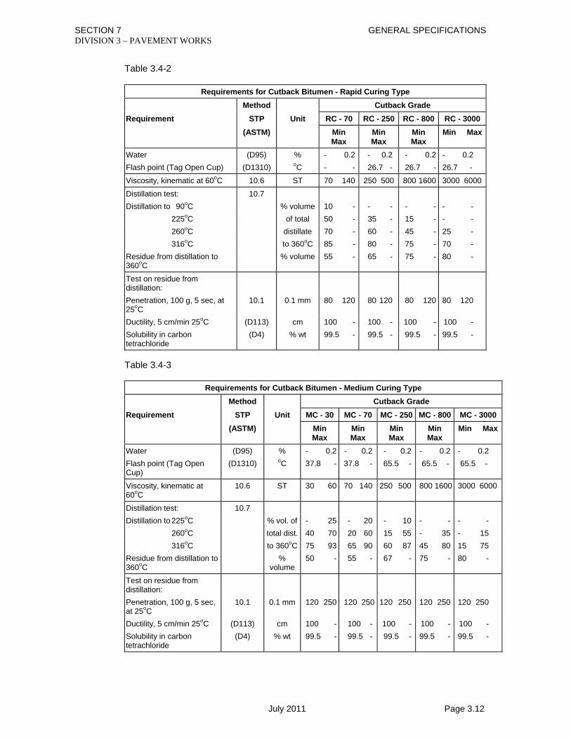
SECTION 7 GENERAL SPECIFICATIONS DIVISION 3 – PAVEMENT WORKS
July 2011 Page 3.12
Table 3.4-2
Requirements for Cutback Bitumen - Rapid Curing Type Method Cutback Grade Requirement STP Unit RC - 70 RC - 250 RC - 800 RC - 3000 (ASTM) Min
Max Min Max
Min Max
Min Max
Water (D95) % - 0.2 - 0.2 - 0.2 - 0.2Flash point (Tag Open Cup) (D1310) oC - - 26.7 - 26.7 - 26.7 -
Viscosity, kinematic at 60oC 10.6 ST 70 140 250 500 800 1600 3000 6000
Distillation test: 10.7 Distillation to 90oC % volume 10 - - - - - - - 225oC of total 50 - 35 - 15 - - - 260oC distillate 70 - 60 - 45 - 25 - 316oC to 360oC 85 - 80 - 75 - 70 - Residue from distillation to 360oC
% volume 55 - 65 - 75 - 80 -
Test on residue from distillation:
Penetration, 100 g, 5 sec, at 25oC
10.1 0.1 mm 80 120 80 120 80 120 80 120
Ductility, 5 cm/min 25oC (D113) cm 100 - 100 - 100 - 100 - Solubility in carbon tetrachloride
(D4) % wt 99.5 - 99.5 - 99.5 - 99.5 -
Table 3.4-3
Requirements for Cutback Bitumen - Medium Curing Type
Method Cutback Grade Requirement STP Unit MC - 30 MC - 70 MC - 250 MC - 800 MC - 3000 (ASTM) Min
Max Min Max
Min Max
Min Max
Min Max
Water (D95) % - 0.2 - 0.2 - 0.2 - 0.2 - 0.2Flash point (Tag Open Cup)
(D1310) oC 37.8 - 37.8 - 65.5 - 65.5 - 65.5 -
Viscosity, kinematic at 60oC
10.6 ST 30 60 70 140 250 500 800 1600 3000 6000
Distillation test: 10.7 Distillation to 225oC % vol. of - 25 - 20 - 10 - - - - 260oC total dist. 40 70 20 60 15 55 - 35 - 15 316oC to 360oC 75 93 65 90 60 87 45 80 15 75 Residue from distillation to 360oC
% volume
50 - 55 - 67 - 75 - 80 -
Test on residue from distillation:
Penetration, 100 g, 5 sec, at 25oC
10.1 0.1 mm 120 250 120 250 120 250 120 250 120 250
Ductility, 5 cm/min 25oC (D113) cm 100 - 100 - 100 - 100 - 100 - Solubility in carbon tetrachloride
(D4) % wt 99.5 - 99.5 - 99.5 - 99.5 - 99.5 -

SECTION 7 GENERAL SPECIFICATIONS DIVISION 3 – PAVEMENT WORKS
July 2011 Page 3.13
When cutback bitumen of the specified grade is not available from commercial suppliers the Contractor shall give full details of his proposed methods of producing cutback bitumen and the Engineer shall order all necessary tests to ensure the material so produced is satisfactory for the intended use.
3.4.2.3 Bitumen Emulsion
Anionic bitumen emulsion shall conform to the requirements for the appropriate grade, given in Table 3.4-4. Cationic bitumen emulsion, shall conform to the requirements for the appropriate grade, given in Table 3.4-5. Bitumen emulsion shall be intended when material is referred to as “emulsified asphalt”. Bitumen emulsion shall conform in all respects to Bangladesh Standard Specification BDS 867, 1978. Table 3.4-4
Specification for Anionic Emulsified Asphalts
Class of Anionic Road Emulsion Property
Labile
Semi-stable
Stable
Slurry Seal
AI - 60 AI - 55 AI - 40 A2 - 57 A2 - 50 A3 A4
Residue on 710 µm BS sieve (% by mass maximum)
0.05 0.05 0.05 0.05 0.05 0.05 0.05
Residue on 150 µm BS sieve (% by mass maximum)
0.15 0.15 0.15 0.15 0.15 0.15 0.15
Stability to mixing with coarse aggregate (% coagulation)
20 - 80 20 - 80 20 - 80 < 40 < 40 < 5 < 5
Stability to mixing with cement (% coagulation)
- - - > 2 > 2 > 2 -
Binder content (minimum % by mass) 58 53 38 55 48 55 56 Viscosity (oEngler 20oC) 6 - 9 5 - 8 4 max 8 max 5 max 9 max 8 max Coagulation of emulsion at low temperature
nil nil nil nil nil nil nil
Storage stability (short period test) (inversions to clear sediment, maximum)
60
60
60
60
60
60
60
Storage stability (long period test) (water content difference % maximum)
2
2
2
2
2
2
2
Particle charge negative negative negative negative negative negative negative

SECTION 7 GENERAL SPECIFICATIONS DIVISION 3 – PAVEMENT WORKS
July 2011 Page 3.14
Table 3.4-5
Specification for Cationic Bitumen Emulsion Class of Cationic Road Emulsion Property
Rapid Acting
Medium Acting
Slow Acting
KI - 70 KI - 60 KI - 40 K2 K3
Residue on 710 µm BS sieve (% by mass maximum)
- 0.05 0.05 0.05 0.05
Residue on 150 µm BS sieve (% by mass maximum)
- 0.15 0.15 0.15 0.15
Binder contents (minimum % by mass) 67 57 38 57 56 Viscosity (oEngler 20oC) - 6 - 9 4 max 10 max 10 max Viscosity Redwood No. II (s at 85oC) 25.35 - - - - Coagulation of emulsion at low temperature - nil nil nil nil Storage stability (short period test) (inversions to clear sediment)
-
60
60
60
60
Storage stability (long period test) (water content difference % maximum)
-
2
-
2
2
Particle charge positive positive positive positive positive 3.4.3 Methods of Storage, Handling and Application.
Bituminous materials shall be handled and stored with due regard for safety and in such a way that at the time of use in the work the materials conform to the Specifications. In particular, bitumen emulsion shall be handled with care and not subjected to mechanical shocks or extremes of temperature likely to cause separation of the bitumen. Bitumen emulsion showing signs of separation shall not be used. The bitumen shall be applied at the temperature range called for in Table 3.4-6 for the particular material being used. Table 3.4-6
Spraying Temperatures For Bitumen
Type Grade Temperature (oC)
Cut-Backs R.C. or M.C. 30 38 - 57
70 57 - 71
250 77 - 94
800 99 - 113
3,000 118 - 132
Penetration Grade Bitumen 60 - 70 151 - 161
80 - 100 151 - 161
200 - 300 138 - 151
Emulsion: As necessary for uniform spraying and satisfactory penetration

SECTION 7 GENERAL SPECIFICATIONS DIVISION 3 – PAVEMENT WORKS
July 2011 Page 3.15
3.4.4 Measurement
Measurement of bituminous material shall be either in metric tons or in litres as indicated in the Contract Documents. The measured quantity shall be the quantity theoretically required to comply with the Contract, or shall be the quantity used and accepted, whichever is the less.
3.4.5 Payment
This work shall be paid for as provided in the Section of the Specifications dealing with the work incorporating the bituminous material and shall be full compensation for complying with that Section of the Specifications as well as this Section.

SECTION 7 GENERAL SPECIFICATIONS DIVISION 3 – PAVEMENT WORKS
July 2011 Page 3.16
3.5 GENERAL REQUIREMENTS FOR BITUMEN BOUND SURFACING (PLANT METHOD)
3.5.1 Description
3.5.1.1 General
This work shall cover the general requirements that are applicable to all types of bituminous bound surfacing irrespective of gradation of mineral aggregate, kind and amount of bituminous material, or use. Deviations from these general requirements are indicated in the specific requirements as set forth in the respective Sections of the Specifications. Section 3.6 is for Prime Coats Section 3.7 is for Tack Coats Section 3.8 is for Primer Seal Section 3.9 is for Bituminous Surface Treatment (Plant Method). Section 3.10 is for Dense Bituminous Surfacing (Plant Method). Section 3.11 is for Pre Mix Bituminous Surfacing (Manual Method). Section 3.12 is for Premix Bituminous Seal Coat (Manual Method). The work shall consist of one or more courses of pre-mixed bituminous mixtures constructed on a prepared and accepted base course or other roadbed in accordance with Sections of these Specifications and in conformity with the required lines, levels, grades, dimensions and typical cross sections.
3.5.1.2 General Composition of Mixtures
The bituminous mix shall be composed basically of coarse mineral aggregate, fine mineral aggregate, filler, and bituminous material. The several mineral constituents shall be sized, uniformly graded, and combined in such proportions that the resulting blend meets the grading requirements for the specific type under the Contract. To such composite blended aggregate shall be added bitumen within the percentage limits set in the specifications for the specific type.
3.5.1.3 Formula for Job-Mix
Before starting work, the Contractor shall submit in writing to the Engineer a job-mix formula for each type of proposed asphaltic mixture. This shall state the sources and types of the various materials to be used, the mixing proportions of the various constituents, the method of mixing, the methods of heating bitumen and aggregates (including means of temperature control) and the means of transportation, laying and compaction. The formula so submitted shall stipulate a single definite temperature for the emptying of the mixture from the mixer, and, for mixtures to be laid hot, a single definite temperature at which the mixture is to be delivered on the road, all of which shall fall within the ranges of the general composition and temperature limits. The job-mix formula for the mixture shall indicate the percentage of aggregate passing each required sieve size and the percentage of bitumen to be added to the aggregate. The contractor shall not commence bituminous surfacing work until the job mix formula has been approved in writing by the Engineer, including any adjustments to the job mix formula which the Engineer considers are necessary. Following approval of the mix formulae the Contractor shall produce trial mixes and lay trial sections of surfacing for each formula. As many samples of the materials shall be taken and tested as the Engineer considers necessary for checking the required uniformity of the mixture and ensuring compliance with the Specification. Following
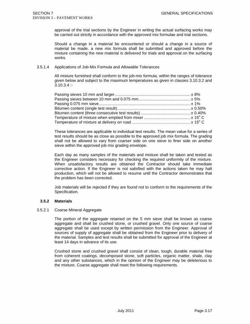
SECTION 7 GENERAL SPECIFICATIONS DIVISION 3 – PAVEMENT WORKS
July 2011 Page 3.17
approval of the trial sections by the Engineer in writing the actual surfacing works may be carried out strictly in accordance with the approved mix formulae and trial sections. Should a change in a material be encountered or should a change in a source of material be made, a new mix formula shall be submitted and approved before the mixture containing the new material is delivered for trials and approval on the surfacing works.
3.5.1.4 Applications of Job-Mix Formula and Allowable Tolerances
All mixture furnished shall conform to the job-mix formula, within the ranges of tolerance given below and subject to the maximum temperatures as given in clauses 3.10.3.2 and 3.10.3.4 :- Passing sieves 10 mm and larger ................................................................... ± 8% Passing sieves between 10 mm and 0.075 mm .............................................. ± 5% Passing 0.075 mm sieve ................................................................................. ± 1% Bitumen content (single test result) ................................................................. ± 0.50% Bitumen content (three consecutive test results) ............................................ ± 0.40% Temperature of mixture when emptied from mixer ......................................... ± 15o C Temperature of mixture at delivery on road .................................................... ± 15o C These tolerances are applicable to individual test results. The mean value for a series of test results should be as close as possible to the approved job mix formula. The grading shall not be allowed to vary from coarser side on one sieve to finer side on another sieve within the approved job mix grading envelope. Each day as many samples of the materials and mixture shall be taken and tested as the Engineer considers necessary for checking the required uniformity of the mixture. When unsatisfactory results are obtained the Contractor should take immediate corrective action. If the Engineer is not satisfied with the actions taken he may halt production, which will not be allowed to resume until the Contractor demonstrates that the problem has been corrected. Job materials will be rejected if they are found not to conform to the requirements of the Specification.
3.5.2 Materials
3.5.2.1 Coarse Mineral Aggregate
The portion of the aggregate retained on the 5 mm sieve shall be known as coarse aggregate and shall be crushed stone, or crushed gravel. Only one source of coarse aggregate shall be used except by written permission from the Engineer. Approval of sources of supply of aggregate shall be obtained from the Engineer prior to delivery of the material. Samples and test results shall be submitted for approval of the Engineer at least 14 days in advance of its use. Crushed stone and crushed gravel shall consist of clean, tough, durable material free from coherent coatings, decomposed stone, soft particles, organic matter, shale, clay and any other substances, which in the opinion of the Engineer may be deleterious to the mixture. Coarse aggregate shall meet the following requirements.

SECTION 7 GENERAL SPECIFICATIONS DIVISION 3 – PAVEMENT WORKS
July 2011 Page 3.18
S.No. Name of Test Testing
Procedure Wearing Course Base Course
1 Aggregate Crushing Value
(ACV) (%)
STP 7.7.1 Less than 25% Less than 30%
2 Los Angeles Abrasion (LAA)
(%)
AASHTO T96 Less than 30% Less than 35%
3 Water absorption STP 7.5.4 Not more than 2% Not more than 2% 4 Soundness AASHTO T104 Loss in weight (after 5 cycles) with Sodium
Sulphate solution- not more than 10% 5 Coating & Stripping
Test AASHTO T182 Min. 95% retained coating
When crushed gravel is used, not less than 90% by weight of the particles retained on a 5 mm sieve shall have at least two fractured faces. The flakiness index as determined in accordance with STP 7.3.1 shall not exceed 30%.
3.5.2.2 Fine Mineral Aggregate
The portion of the aggregate passing a 5 mm sieve shall be known as fine mineral aggregate, and shall consist of natural sand, stone screenings, or a combination of both. Stone screenings shall be produced from stone meeting the requirements for coarse mineral aggregate in Section 3.5.2.1. Fine aggregate shall be composed of clean, hard durable particles, rough surfaced and angular, free from vegetable matter, soft particles, clay balls or other objectionable material. The PI for material passing the 0.425 mm sieve shall be less than 4. Sand Equivalent of material passing 4.75 mm sieve, when tested in accordance with AASHTO T176, shall be minimum 50. When the fine aggregate is tested for soundness as per AASHTO T104, the loss in weight after 5 cycles with sodium sulphate shall not exceed 15%. Approval of sources of supply of aggregate shall be obtained from the Engineer prior to delivery of the material. Samples and test results shall be submitted for approval of the Engineer at least 14 days in advance of its use.
3.5.2.3 Mineral Filler
Mineral filler where required shall consist of limestone dust, dolomite dust, or similar rock dust, Portland cement, hydrated lime, silica cement or other mineral matter from sources approved by the Engineer. It shall be non plastic and free from foreign or other objectionable material. It shall be dry and free from lumps and when tested by means of laboratory sieves shall meet the following grading requirements:
Sieve Designation
Percentage by Weight (STP 3.3)
0.600 mm 100 0.150 mm 95 - 100 0.075 mm 65 - 100
Mineral filler shall be considered to include any mineral dust naturally present in the bitumen.

SECTION 7 GENERAL SPECIFICATIONS DIVISION 3 – PAVEMENT WORKS
July 2011 Page 3.19
Approval of sources of supply of mineral filler shall be obtained from the Engineer prior to delivery of the material. Samples and test results shall be submitted for approval of the Engineer at least 14 days in advance of its use.
3.5.2.4 Bituminous Materials
Details as to the source and type of bitumen must be submitted for approval at least 14 days before the proposed use of the material and should conform to the requirements of Section 3.4. The Engineer may instruct for samples of the bitumen to be taken from the consignment before leaving the place of manufacture and that these should be forwarded to a laboratory nominated by the Engineer for analysis and testing. The material from which these samples for testing are taken must be segregated at the place of manufacture until the satisfactory completion of the aforesaid tests permit release. Each consignment of bituminous material delivered to the site must be accompanied by a certificate showing the place of manufacture and the results of standard tests carried out on the bulk supply from which the material was extracted. No bituminous material other than that represented by the sample submitted shall be used by the Contractor except with the written consent of the Engineer. The contractor shall, in accordance with Specification Clause 1.3.2 and when so directed by the Engineer, arrange for sampling and testing, at an approved testing laboratory, of all bituminous materials delivered to and stored at site. Blending of bituminous materials from different refineries shall not be permitted.
3.5.3 Construction
3.5.3.1 Weather Limitation
Bituminous mixtures shall be placed only when the surface is dry, when rain does not appear imminent and when the prepared roadbed is in a satisfactory condition. However, the Engineer may permit, in case of sudden rain, the placing of mixture then in transit from the plant, if laid at proper temperature and if the roadbed is free from pools of water. Such permission shall in no way relax the requirements for quality and smoothness of surface.
3.5.3.2 Progress of Work
No work shall be performed when there is insufficient hauling, spreading or finishing equipment, or labour, to ensure progress at a rate not less than 60% of the capacity of the mixing plant.
3.5.3.3 Plant and Equipment
A) Requirements for all Mixing Plants All plant used by the Contractor for the preparation of bituminous mixtures shall conform to all of the requirements below, except that scale requirements shall apply only where weight proportioning is used; and in addition, any batch mixing plants shall conform only to the relevant special requirements herein and any continuous mixing plants shall conform only to the relevant special requirements herein. The mixing plant, which can be a batching plant or a continuous mixing plant, shall have a capacity sufficient to supply the paver on the road continuously when spreading the bituminous mix at normal speed and required thickness.
1) Uniformity. The plants shall be so designed, co-ordinated and operated as to produce a mixture within the job - mix tolerances.

SECTION 7 GENERAL SPECIFICATIONS DIVISION 3 – PAVEMENT WORKS
July 2011 Page 3.20
2) Plant scales and weigh house. Scales for any weigh box or hopper may be either of
the beam or spring less dial type and shall be of a standard make and design accurate to within one-half of 1 percent of the maximum load required.
Scales shall be approved by the Engineer and shall be checked as often as the Engineer may deem necessary to ensure their continued accuracy.
The Contractor shall provide and have at hand not less than ten 25 kilogram weights for frequent testing of all scales.
3) Equipment for preparation of bituminous material. Tanks for storage of bituminous
material shall be capable of heating the material under effective and positive control at all times, to a temperature within the range specified. The circulating system for the bituminous material shall be of adequate size to ensure proper and continuous circulation during the entire operating period. Suitable means shall be provided for maintaining the specified temperature of the bituminous material in the pipe lines, meters, weigh buckets, spray bars, and other containers or flow lines. The storage tank capacity shall be sufficient for at least 1 day’s run. Bituminous material may be partially heated in the tanks and brought to the specified temperature by means of booster heating equipment between the tanks and the mixer.
4) Feeder for drier. The plant shall be provided with an accurate mechanical means for
uniformly feeding the mineral aggregate into the drier so that uniform production and uniform temperatures are obtainable.
5) Drier. A rotary drier of approved design for drying and heating the mineral aggregate
shall be provided. The drier shall be capable of drying and heating the mineral aggregate to the specified temperature.
6) Screens. Plant screens, capable of screening all aggregate to the specified sizes
and proportions and having normal capacities slightly in excess of the full capacity of the mixer, shall be provided. The screens shall be readily exposed for inspection by the Engineer.
7) Bins. The plant shall include storage bins of sufficient capacity to supply the mixer
when it is operating at full capacity. Bins shall be divided into at least three compartments and shall be arranged to ensure separate and adequate storage of appropriate fractions of the aggregate. For a mineral filler admixture a separate feeder bin and/or weighing hopper arrangement may be required. Bins shall be so constructed that representative samples can readily be obtained, and the aggregate level observed.
8) Bituminous control unit. Satisfactory means either by weighing or metering shall be
provided to obtain the proper amount of bituminous material in the mix within the tolerance specified for the job-mix.
For use with batching plants, it shall provide the designated quantity of bituminous material for each batch. For continuous mixing plants, the operating speed of the pump shall be synchronised with the flow of aggregate in the mixer by an automatic locking control, and the device shall be easily and accurately adjustable. Means shall be provided for checking the quantity or rate of flow of bituminous material into the mixer. An accuracy within 1% of the specified amount is required.
9) Thermometric equipment. An armoured thermometer reading from 50°C to 200°C shall be fixed in the bituminous feed line at a suitable location near the discharge valve at the mixer unit.

SECTION 7 GENERAL SPECIFICATIONS DIVISION 3 – PAVEMENT WORKS
July 2011 Page 3.21
The plant shall be further equipped with a thermometric instrument so placed at the discharge chute of the drier as to register automatically or indicate the temperature of the heated aggregate.
10) Dust collector. The plant shall be equipped with a dust collector constructed to
waste or return uniformly to the elevator all or any part of the material collected. The material to be returned from the dust collector shall be weighed over the filler scale.
11) Control of mixing time. The plant shall be equipped with accurate positive means to
govern the time of mixing and to maintain it constant unless changed at the direction of the Engineer. The time of mixing shall be considered as the interval between the time the bituminous material is spread on the aggregate and the time the same aggregate leaves the mixing unit.
When bitumen is applied by a spray system, the mixing time shall begin with the start of the bitumen spray. When the bitumen is not applied by a spray system, a minimum dry mixing period of five seconds shall precede the addition of the bitumen to the mix.
12) Safety requirements. Adequate and safe stairways to the mixer platform and
guarded ladders to other plant units shall be placed at all points required for accessibility to all plant operations. All gears, pulleys, chains, sprockets, and other dangerous moving parts shall be thoroughly guarded and protected. Ample and unobstructed space shall be provided on the mixing platform. A clear and unobstructed passage shall be maintained at all times in and around the truck loading space. This space shall be kept free from drippings from the mixing platform. Flexible pipe connections carrying hot bitumen shall be shielded.
B) Special Requirements for Batch Mix Plants
1) Weigh box or hopper. The equipment shall include a means for accurately weighing each bin size of aggregate in a weigh box or hopper, suspended on scales, ample in size to hold a full batch without hand raking or running over. The weigh box or hopper shall be supported on fulcrums and knife edges so constructed that they will not easily be thrown out of alignment or adjustment. All edges, ends, and sides of weighing hoppers shall be free from contact with any supporting rods, columns or other equipment that will in any way affect the proper functioning of the hopper. There shall also be sufficient clearance between hoppers and supporting devices to prevent accumulations of foreign materials. The discharge gate of the weigh box shall be so hung that the aggregates will not be segregated when dumped into the mixer and shall close tightly when the hopper is empty so that no material is allowed to leak into the batch in the mixer during the process of weighing the next batch.
2) Mixer. The batch mixer shall be capable of producing a continuous uniform mixture
within the job - mix tolerances. It shall be of such design as to permit visual inspection of the mix.
The mixer shall be equipped with a sufficient number of paddles or blades with proper arrangement to produce a properly and uniformly mixed batch. The clearance of blades from all fixed and moving parts shall not exceed 20 mm unless the maximum diameter of the aggregate particle in the mix exceeds 25 mm.
C) Special Requirements for Continuous Plants
1) Gradation control unit. The plant shall include a means for proportioning accurately each bin size of aggregate either by weighing or by volumetric measurement.

SECTION 7 GENERAL SPECIFICATIONS DIVISION 3 – PAVEMENT WORKS
July 2011 Page 3.22
When gradation control is by volume, the unit shall include a feeder mounted under the compartment bins. Each bin shall have an accurately controlled individual gate to form an orifice for volumetrically measuring the materials drawn from each respective bin compartment. Indicators shall be provided for each gate to show the respective gate opening in centimetres.
2) Weight calibration of aggregate feed. The plant shall include provision for a
calibration of the gate openings by means of weight test samples so that each of the materials fed out of the bins through individual orifices may be by-passed satisfactorily to suitable test boxes, each bin material being confined separately.
The plant shall be equipped to handle conveniently such test samples weighing not less than 150 kilograms combined weight of samples from all bins, and not less than 50 kilograms for any one bin sample.
3) Synchronisation of aggregate and bitumen feed. Satisfactory means shall be
provided to afford positive interlocking control between the flow of aggregate from the bins and the flow of bitumen from the meter or other proportioning source. This control shall be accomplished by interlocking mechanical means or by a positive method satisfactory to the Engineer.
4) Mixer. The plant shall include a continuous mixer of an approved type capable of
producing a continuous uniform mixture within the job - mix tolerances.
Determination of the mixing time shall be by a weight method, using the following formula (the weights shall be determined for the job): -
Mixing time in seconds = Pugmill dead capacity in kilograms Pugmill output in kilograms per second
5) Hopper. The mixer shall be equipped with a hopper at the discharge end, of such size and design that no segregation of mix occurs. Any elevator used for loading mixture into vehicles shall have an equally satisfactory hopper.
D) Equipment for Hauling and Placing 1) Trucks. Trucks for hauling bituminous mixtures shall have tight, clean and smooth
metal beds that have been sprayed with soapy water, thinned fuel oil, paraffin oil, or lime solution to prevent the mixture from adhering to the beds. The amount of sprayed fluid shall however be kept to the practical minimum. Each load shall be covered with canvas or other suitable material of such size as to protect the mixture from the weather. Any truck causing excessive segregation of material by its spring suspension or other contributing factors, or that shows oil leaks in detrimental amounts, or that causes undue delays, shall upon direction of the Engineer be removed from the Works until such conditions are corrected. When necessary, in order that the mixture shall be delivered on the road at the specified temperature, truck beds shall be insulated to maintain workable temperature of the mixture and all covers shall be securely fastened.
Trucks or any other equipment leaking petroleum products will not be allowed admittance to paved areas or areas where paving is under construction.
2) Spreading and finishing equipment. The equipment for spreading and finishing shall
be approved mechanical, self powered pavers, capable of spreading and finishing the mixture true to the lines, grades, levels dimensions and cross sections.
The pavers shall be equipped with hoppers and distributing screws of the reversing type to place the mixture evenly in front of adjustable screeding devices and shall have reverse as well as forward travelling speeds.

SECTION 7 GENERAL SPECIFICATIONS DIVISION 3 – PAVEMENT WORKS
July 2011 Page 3.23
The pavers shall maintain the grade and confine the edges of the pavement to true lines without the use of stationary side forms. The equipment shall include blending or joint levelling devices for smoothing and adjusting longitudinal joints between lanes. The assembly shall be adjustable to give the cross-section shape prescribed and shall be so designed and operated as to place the thickness or weight per square metre of material required.
Pavers shall be equipped with activated screeds and devices for heating the screeds to the temperature required for the laying of the mixture without pulling or marring.
The term “screed” includes any cutting, crowding, or other practical action that is effective in producing a finished surface of the evenness and texture specified, without tearing, shoving, or gouging.
If, during construction, it is found that the spreading and finishing equipment in operation leaves in the pavement surface tracks or indented areas of other objectionable irregularities that are not satisfactorily corrected by scheduled operations, the use of such equipment shall be discontinued and other satisfactory spreading and finishing equipment shall be provided by the Contractor forthwith.
Rollers shall be pneumatic typed rollers and smooth wheel rollers with or without vibration. The rolling procedure is described in Section 3.5.3.4.
3) Small tools. The Contractor shall provide suitable means for keeping all small tools
clean and free from accumulation of bituminous material. He shall provide and have ready for use at all times enough tarpaulins or covers, as may be directed by the Engineer, for use in any emergency such as rain, chilling wind, or unavoidable delay, for the purpose of covering or protecting any material that may have been dumped and not spread.
3.5.3.4 Preparation and Placing
A) Preparation of Existing Surface Where local irregularities in an existing surface would otherwise result in a course more than 75 mm thick after compaction, the surface shall be brought to uniform contour by patching with a bituminous mixture to be approved by the Engineer, and thoroughly tamping or rolling until it conforms with the surrounding surface. The mixture used shall be the same as that specified for the next course, unless the size of the largest aggregate in the mixture precludes this when the Engineer will decide the mixture to be used. Where the existing roadbed is broken or shows instability, the unstable material shall be removed and disposed of as directed by the Engineer and be replaced with the same mixture as specified for the next course, compacted to the standard and elevation of the adjacent surface. The surface upon which the mixture is to be placed shall be swept thoroughly and cleaned of all loose dirt and other objectionable material immediately before spreading the mixture. B) Preparation of Bituminous Material The bituminous material shall be heated to the specified temperature in kettles or tanks so designed as to avoid local overheating and to provide a continuous supply of the bituminous material to the mixer at a uniform temperature at all times.

SECTION 7 GENERAL SPECIFICATIONS DIVISION 3 – PAVEMENT WORKS
July 2011 Page 3.24
C) Preparation of Mineral Aggregate The mineral aggregates for the mixture shall be dried and heated before being placed in the mixer. Flames used for drying and heating shall be adjusted properly to avoid adversely affecting the aggregate and to avoid forming a heavy coating of soot on the aggregate. The aggregates shall be heated to the temperature specified in the applicable Section. The aggregates, immediately after heating, shall be screened into three or more fractions and conveyed into separate bins ready for combining and mixing with bituminous material. The fraction of aggregate deposited in any bin shall not contain more than 10% of material outside the specified size limits for that bin.
D) Preparation of Mixture The dried mineral aggregates prepared as prescribed above, shall be combined in the amount of each fraction of aggregate required to meet the job-mix formula for the particular mixture. The bituminous material shall be measured or gauged and introduced into the mix in the amount determined in the job mix formula. The proper amount of bituminous material shall be distributed over the mineral aggregate and the whole thoroughly mixed for a period of at least 30 seconds, or longer if necessary to produce a homogeneous mixture in which all particles of the mineral aggregate are coated uniformly. For a continuous mixing plant, the mixing time shall be determined from the formula in Section 3.5.3.3(C)(4) and may be regulated by fixing a minimum gauge in the mixer unit and/or by other mixing unit adjustment. E) Transportation and Delivery of Mixture The mixture shall be transported from the mixing plant to the point of use in vehicles conforming to the requirements of Section 3.5.3.3(D)(1). Loading and transporting shall be such that spreading, compaction and finishing shall all be carried out during daylight hours unless satisfactory illumination is provided by the Contractor. F) Spreading and Finishing Upon arrival at the point of use, the mixture shall be spread and struck off to the grade, elevation, and cross-section shape intended, either over the entire width or over such partial width as may be practicable. Bituminous mixture pavers conforming to the requirements of Section 3.5.3.3(D)(2) shall be used for this purpose. The mixture shall be laid upon an approved surface and only when weather conditions are considered suitable by the Engineer. In narrow base widening, deep or irregular sections, turn outs or driveways where it is impractical to spread and finish the mixture by use of a paver, the Contractor shall use approved spreading equipment or acceptable hand methods as directed by the Engineer. On areas where in the opinion of the Engineer, the use of spreading equipment is considered impractical, the mixture shall be dumped on steel boards then spread, raked and luted by hand to provide the correct weight or uniform thickness of material without segregation. Mixture shall not be applied faster than can be properly handled and spread. G) Compaction of Mixture 1) General. Immediately after the mixture has been spread and struck off, the surface
shall be checked and any inequalities adjusted. The mixture shall then be thoroughly

SECTION 7 GENERAL SPECIFICATIONS DIVISION 3 – PAVEMENT WORKS
July 2011 Page 3.25
and uniformly compacted by rolling. Each course shall be rolled as soon after being placed as the material will support the roller without undue displacement or cracking.
2) Roller Requirements. With each paver, two steel wheeled tandem rollers and one
pneumatic tyred roller will be required.
All rollers shall be self propelled, capable of being reversed without backlash and equipped with power steering, dual controls allowing operation from either the right or left side, water tanks, sprinkler systems and coco-mats to ensure even wetting of rolls or tyres. The Contractor shall supply to the Engineer for each type of roller a calibration chart showing the relation between depth of ballast and weight and giving the tare weight of the roller. Each roller shall be in good condition and worked by a competent and experienced operative.
Steel wheeled tandem rollers shall weigh not less than 8 metric tons and each tandem roller used for final compaction (finish rolling) shall have at least one roll capable of applying a minimum rolling pressure of 35 kilograms per centimetre of roll width. Pneumatic tyred rollers shall be of an approved type having not less than seven wheels with smooth treat compactor tyres of equal size and construction capable of operating at inflation pressures up to 8.5 kg/cm². Wheels shall be equally spaced along both axle lines and arranged so that tyres on one axle line track midway between those on the other with an overlap. Each tyre shall be kept inflated to the specified operating pressure such that the pressure difference between any two tyres shall not exceed 0.35 kg/cm². Means shall be provided for checking and adjusting the tyre pressures on the job at all times. Each roller shall be so equipped that its total weight is adjustable by ballasting allowing the load per wheel to be varied from 1,500 to 2,500 kilograms. In operation, the tyre inflation pressure and the wheel load shall be adjusted, as required by the Engineer, to meet the requirements of each particular application. In general the compaction of any course with a pneumatic tyred roller shall be accomplished with contact pressures as high as the material will support.
3) Procedure. Rolling of the mix shall consist of six separate operations as follows:
• transverse joint • longitudinal joint • edges • initial or breakdown rolling • second or intermediate rolling • finish rolling
The first rolling of all joints and edges, the initial or breakdown rolling and the final or finish rolling shall all be done with the steel wheeled tandem rollers. The second or intermediate rolling shall be done with the pneumatic tyred roller except on small operations. Rolling shall start longitudinally at the sides and proceed toward the centre of the pavement except that on super-elevated curves rolling shall begin at the low side and progress toward the high side. Successive trips of the roller shall overlap by at least one half of the width of the roller and alternative trips shall not terminate at the same point. For initial rolling, the drive roll should be nearest the paver. The speed of the rollers shall not exceed 4 kilometres per hour for steel wheeled rollers and 6 kilometre per hour for pneumatic tyred rollers and shall at all times be slow enough to avoid displacement of the hot mixture. Any displacements occurring as a result of reversing the direction of the roller or from any other cause shall at

SECTION 7 GENERAL SPECIFICATIONS DIVISION 3 – PAVEMENT WORKS
July 2011 Page 3.26
once be corrected with rakes and fresh mixture where required. Care shall be exercised in rolling not to displace the line and grade of the edges. Rolling shall progress continuously as may be necessary to obtain uniform compaction while the mixture is in a workable condition and until all roller marks are eliminated. Heavy equipment or rollers shall not be permitted to stand on the newly laid surface until it has thoroughly cooled. To prevent adhesion of the mixture to the roller, the wheels shall be kept properly moistened, but excess water will not be permitted. Any petroleum products dropped or spilled from the vehicles or equipment employed by the Contractor upon any portion of the pavement under construction is cause for the removal and replacement of the contaminated pavement by the Contractor. Along kerbs, headers, manholes, and similar structures and at all places not accessible to the roller, thorough compaction shall be secured by means of hot hand tampers or with mechanical tampers giving equivalent compaction. Each hand tamper shall weigh not less than 10 kilograms and shall have a tamping face area of not more than 250 square centimetres. The surface of the mixture after compaction shall be smooth and true to the established crown and grade within the tolerance specified. Any mixture that becomes loose and broken, mixed with dirt, or which is defective in any way, shall be removed and replaced with fresh hot mixture, which shall be compacted immediately to conform with the surrounding area. Any area of 1,000 square centimetres or more showing an excess or deficiency of bituminous material shall be removed and replaced. All high spots, high joints, depressions, and honeycombs shall be adjusted as directed by the Engineer.
H) Joints Both longitudinal and transverse joints in successive courses shall be staggered so as not to be one above the other. Longitudinal joints shall be staggered a minimum of 20cm and so arranged that the longitudinal joint in the top course shall be at the location of the line dividing the traffic lanes. Lateral joints shall be staggered a minimum of 100cm centimetres and shall be straight. Spreading shall be as nearly continuous as possible and rollers shall pass over the unprotected end of freshly laid mixture only when authorised by the Engineer. In all such cases provision shall be made for a properly bonded and sealed joint with the new surface for the full depth of the course as specified above. Before placing mixtures against them, all contact surfaces of kerbs, gutters, headers, manholes etc. shall be given a thin uniform coating of hot bitumen and the joints between these structures and the surface mixture shall be effectively sealed by the subsequent spreading, finishing and compaction operations. When the wearing course is placed adjacent to kerbs to form a bitumen gutter it shall be sealed with bitumen for a distance of 30 centimetres from the kerb. The seal shall be evenly applied to the surface by means of hot irons or squeegees so that the surface voids are completely filled and no excess bitumen remains on the surface. The desired drainage pattern shall be maintained.
3.5.3.5 Surface Test of the Pavement
The finished surface of the pavement for both base (binder) and wearing courses shall not vary from the specified levels and grades by more than ±5mm. The surface shall be also tested by a crown template and 3 metre straight edge, furnished by the Contractor, applied

SECTION 7 GENERAL SPECIFICATIONS DIVISION 3 – PAVEMENT WORKS
July 2011 Page 3.27
respectively at right angles and parallel, to the centreline of the road. The Contractor shall designate some employees to use the template and straight edge under the direction of the Engineer in checking all surfaces. The crown template shall conform to the typical cross section shown on the Drawings. The variation of the surface from the testing edge of the crown template and the straight edge between any two contacts with the surface shall not exceed 5 millimetres for both binder and wearing courses. Tests for conformity with the specified crown and grade shall, when agreed by the Engineer, be made immediately after initial compaction and variations shall be corrected by removing or adding materials as may be necessary. Rolling shall then be continued as specified. After final rolling, the smoothness of the course shall be checked again and any irregularity of the surface exceeding the above limits and any areas defective in texture, compaction, or composition, shall be corrected as directed by the Engineer, including removal and replacement at the Contractor’s expense if so directed by the Engineer. The average thickness of the compacted bituminous layer, as computed from 5No successive determinations for every 400 to 800 m2 of pavement area, shall not be less than the specified thickness nor shall any particular point be thinner than 5mm less than the specified thickness. Any section of paving having thickness measurements outside these limits shall be rectified at the contractor’s expense as directed by the Engineer, including where necessary removal and replacement. In case of removal and relaying of the pavement layer a minimum length of 50m shall be removed for its full width. The edges of the pavement shall follow a smooth alignment and, where not bound by kerbs or other edgings, shall not deviate from the specified alignment by more than ±20mm. Any material laid out of alignment is to be corrected as directed by the Engineer. Excess material shall be cut off square after final rolling, and disposed of by the Contractor.
3.5.3.6 Control and Testing
The Contractor shall supply qualified personnel to be in charge of the tests and controls required to ensure correct operation of the plant and the manufacture of a satisfactory product. The Contractor shall keep a diary and maintain records of times, batch numbers, areas paved and other observations, and he shall follow such instructions as may be given by the Engineer in order to obtain the required quality of the bituminous bound material.
3.5.4 Measurement
All work prescribed above shall be measured and paid for as provided in the respective Sections for each type of pavement. The quantity measured and paid for shall always be the quantity ordered with any permitted excess, or the actual quantity used whichever is the less.
3.5.5 Payment
The work shall be paid for as provided in the respective Section for each type of bituminous layer.

SECTION 7 GENERAL SPECIFICATIONS DIVISION 3 – PAVEMENT WORKS
July 2011 Page 3.28
3.6 BITUMINOUS PRIME COAT
3.6.1 Description
This work shall consist of the careful cleaning of the surface to be primed and furnishing and applying bituminous material in accordance with these Specifications to the area shown on the Drawings or as directed by the Engineer.
3.6.2 Materials
3.6.2.1 Bituminous Materials
Bituminous material shall be a MC 30 or MC 70 cut back bitumen and shall conform to the requirements of Section 3.4. The bituminous material shall be approved by the Engineer and may be prepared by cutting back 80/100 penetration bitumen with kerosene in the ratio of 100 parts by volume of bitumen to 40 – 60 parts by volume of kerosene depending on the porosity of the surface.
3.6.2.2 Blotting Material
Blotting material shall be approved clean dry sand or stone screenings free from any cohesive materials or organic matter. Not more than 10 per cent of the sand shall be finer than the 75 micron sieve.
3.6.3 Construction Methods
3.6.3.1 Weather Limitations
Prime coat shall be applied at a time when the surface to be treated is dry or slightly damp, when the ambient temperature is above 13ºC and rising, or above 16ºC if falling, and when the weather is dry.
3.6.3.2 Equipment
The Engineer may approve Construction equipment and methods (including labour intensive methods) other than those specified hereinafter provided that the contractor can demonstrate his ability to carry out the work to a satisfactory standard using his proposed equipment and methods to the complete satisfaction of the Engineer. Such approval shall be in writing and may be withdrawn at any time if the work is found to be unsatisfactory in any respect. The equipment used by the Contractor shall include, unless otherwise approved by the Engineer, a power brush, a pressure bituminous distributor, and, when necessary, equipment for heating bituminous material. The distributor shall have pneumatic tyres and shall be so designed, equipped, maintained and operated that bituminous material at constant temperature may be applied uniformly on variable widths of surface up to 4 metres at readily determined and controlled rates of from 0.2 to 2.0 litres per square metre with uniform pressure, and with an allowable variation from any specified rate not to exceed 0.1 litre per square metre. Distribution equipment shall include an instrument for measuring the speed of travel accurately at low speeds, and the temperature of the contents of the tank. The spray bar on the distributor shall be controlled by a man riding at the rear of the distributor in such a position that operation of all sprays is in his full view. The tanks of distributors shall be fitted with accurately calibrated dipsticks or contents gauges.
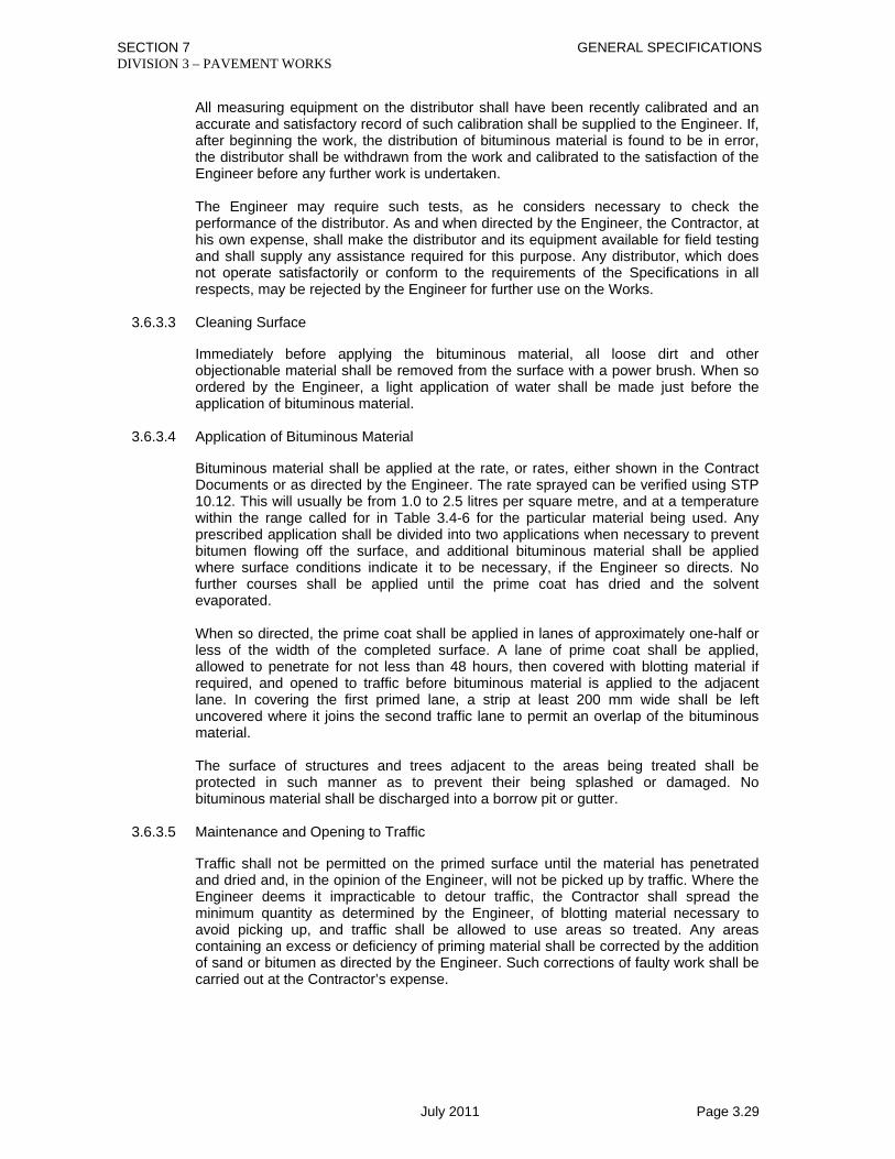
SECTION 7 GENERAL SPECIFICATIONS DIVISION 3 – PAVEMENT WORKS
July 2011 Page 3.29
All measuring equipment on the distributor shall have been recently calibrated and an accurate and satisfactory record of such calibration shall be supplied to the Engineer. If, after beginning the work, the distribution of bituminous material is found to be in error, the distributor shall be withdrawn from the work and calibrated to the satisfaction of the Engineer before any further work is undertaken. The Engineer may require such tests, as he considers necessary to check the performance of the distributor. As and when directed by the Engineer, the Contractor, at his own expense, shall make the distributor and its equipment available for field testing and shall supply any assistance required for this purpose. Any distributor, which does not operate satisfactorily or conform to the requirements of the Specifications in all respects, may be rejected by the Engineer for further use on the Works.
3.6.3.3 Cleaning Surface
Immediately before applying the bituminous material, all loose dirt and other objectionable material shall be removed from the surface with a power brush. When so ordered by the Engineer, a light application of water shall be made just before the application of bituminous material.
3.6.3.4 Application of Bituminous Material
Bituminous material shall be applied at the rate, or rates, either shown in the Contract Documents or as directed by the Engineer. The rate sprayed can be verified using STP 10.12. This will usually be from 1.0 to 2.5 litres per square metre, and at a temperature within the range called for in Table 3.4-6 for the particular material being used. Any prescribed application shall be divided into two applications when necessary to prevent bitumen flowing off the surface, and additional bituminous material shall be applied where surface conditions indicate it to be necessary, if the Engineer so directs. No further courses shall be applied until the prime coat has dried and the solvent evaporated. When so directed, the prime coat shall be applied in lanes of approximately one-half or less of the width of the completed surface. A lane of prime coat shall be applied, allowed to penetrate for not less than 48 hours, then covered with blotting material if required, and opened to traffic before bituminous material is applied to the adjacent lane. In covering the first primed lane, a strip at least 200 mm wide shall be left uncovered where it joins the second traffic lane to permit an overlap of the bituminous material. The surface of structures and trees adjacent to the areas being treated shall be protected in such manner as to prevent their being splashed or damaged. No bituminous material shall be discharged into a borrow pit or gutter.
3.6.3.5 Maintenance and Opening to Traffic
Traffic shall not be permitted on the primed surface until the material has penetrated and dried and, in the opinion of the Engineer, will not be picked up by traffic. Where the Engineer deems it impracticable to detour traffic, the Contractor shall spread the minimum quantity as determined by the Engineer, of blotting material necessary to avoid picking up, and traffic shall be allowed to use areas so treated. Any areas containing an excess or deficiency of priming material shall be corrected by the addition of sand or bitumen as directed by the Engineer. Such corrections of faulty work shall be carried out at the Contractor’s expense.

SECTION 7 GENERAL SPECIFICATIONS DIVISION 3 – PAVEMENT WORKS
July 2011 Page 3.30
3.6.4 Measurement
The quantity of bituminous material shall be measured for payment in square metres; however, in the case of plant placed materials a record of the number of Litres of bituminous material placed will also be kept. The measured quantity shall be the theoretical required to comply with the Contract, or shall be the quantity used and accepted. This should be within ± 5% of the theoretical quantity unless there is a change in the area of coverage.
3.6.5 Payment
This work measured as provided above, shall be paid for at the Contract unit price per unit of measurement. The prices and payment shall be full compensation for preparation of the surface and furnishing and placing the materials and application of blotting materials including all labour, equipment, tools and incidentals necessary to complete the work prescribed in this Section. Pay item shall be: 3/6/1(a) Bituminous Prime Coat (plant placed) Square Metre or 3/6/1(b) Bituminous Prime Coat (hand placed) Square Metre

SECTION 7 GENERAL SPECIFICATIONS DIVISION 3 – PAVEMENT WORKS
July 2011 Page 3.31
3.7 BITUMINOUS TACK COAT
3.7.1 Description
This work shall consist of furnishing and applying bituminous material to a previously prepared roadbed, in accordance with the Specifications and to the width and area required by the Engineer.
3.7.2 Materials
Bituminous material shall be either 60/70 or 80/100 penetration grade bitumen, cut back bitumen RC 30, RC 70 cut back bitumen RC 30, RC 70, or rapid setting emulsion conforming to the requirements of Section 3.4 of these Specifications. The bituminous material shall be approved by the Engineer.
3.7.3 Construction Methods
3.7.3.1 Equipment
The Engineer may approve Construction equipment and methods (including labour intensive methods) other than those specified hereinafter provided that the contractor can demonstrate his ability to carry out the work to a satisfactory standard using his proposed equipment and methods to the complete satisfaction of the Engineer. Such approval shall be in writing and may be withdrawn at any time if the work is found to be unsatisfactory in any respect. The equipment shall be as specified in Section 3.6, Bituminous Prime Coat.
3.7.3.2 Cleaning Surface
The full width of surface to be treated shall be cleaned with a power brush to remove loose dirt, sand, dust and other objectionable material. The surface to be treated shall be dry.
3.7.3.3 Application of Bituminous Material
Immediately after cleaning the surface, bituminous material shall be applied at the rate directed by the Engineer, but not to exceed 0.45 litres per square metre and at the temperature within the range included in Table 3.4-6 for the particular material being used. The tack coat shall be applied only when the surface is dry. The tack coat material shall be uniformly distributed over the surface without streaking. Quantities shall not deviate more than 10% from the quantity prescribed by the Engineer. Quantities outside the specified tolerances shall be adjusted by the Contractor at his own expense, to the satisfaction of the Engineer. The surfaces of structures and trees adjacent to the areas being treated shall be protected in such manner as to prevent their being splashed or damaged. No bituminous material shall be discharged into a borrow pit or gutter. The Engineer may direct that emulsions shall be diluted with clean water in order to control the rate of spread. This shall be done at the Contractor’s expense. After the tack coat is applied the Contractor shall protect it from damage until the surface course is placed. No surfacing layer will be permitted to be placed unless the tack coat is in a satisfactory condition to receive it and as such the tack coat shall be applied only so far in advance of surface course placement as is necessary for this to occur.

SECTION 7 GENERAL SPECIFICATIONS DIVISION 3 – PAVEMENT WORKS
July 2011 Page 3.32
3.7.4 Measurement
The quantity of bituminous material shall be measured for payment in square metres; however, in the case of plant placed materials a record of the number of Litres of bituminous material placed will also be kept. The measured quantity shall be the theoretical required to comply with the Contract, or shall be the quantity used and accepted. This should be within ± 5% of the theoretical quantity unless there is a change in the area of coverage.
3.7.5 Payment
This work measured as provided above, shall be paid for at the Contract price per unit of measurement. The prices and payment shall be full compensation for furnishing and placing the materials, including all labour, equipment, tools and incidental necessary to complete the work. Pay item shall be: 3/7/1(a) Bituminous Tack Coat (plant work) Square Metre or 3/7/1(b) Bituminous Tack Coat (labour intensive work) Square Metre

SECTION 7 GENERAL SPECIFICATIONS DIVISION 3 – PAVEMENT WORKS
July 2011 Page 3.33
3.8 PRIMER SEAL
3.8.1 Description
The work shall consist of an application of bituminous material followed by spreading of pea-gravel, a cover coat material, in accordance with these Specifications to the area shown on the Drawings or as directed by the Engineer.
3.8.2 Materials
3.8.2.1 Bituminous Material
Cutback bitumen conforming to the requirements of section 3.4 as appropriate, shall be used for the purpose. The 80-100 penetration grade bitumen may be converted into cutback by fluxing and thoroughly mixing 4% diesel with the bitumen after it is heated. The method of mixing or fluxing for cutback from 80-100 penetration grade bitumen shall be approved by the Engineer.
3.8.2.2 Cover Coat Material
Cover coat material used for this work shall be screened Pea gravel conforming to the Specification and graded so that 100% of the materials falls within the size range of 2.4 mm to 6.3 mm. Pea-gravel shall be washed by water, dried and be free from any organic matter, clay or any other objectionable matter and completely dust free. Samples of the Pea gravel proposed for use shall be submitted for approval of the Engineer.
3.8.3 Construction Methods
3.8.3.1 Cleaning Surface
The contractor shall furnish all labour and equipment required for thoroughly cleaning the surface to be primed. The cleaning shall be done in such a manner as to thorough remove all mud, dust and other foreign materials. The sweeping on a water bound surface shall be just sufficient to expose the pattern of the coarse aggregate. Any surplus bituminous materials shall be removed from the surface. Special care shall be taken to clean the edges of the road to be primed in order to ensure uniform application of the bituminous materials, directly on the existing base of pavement material.
3.8.3.2 Applying Bituminous Materials
Primer seal work shall be carried out only when the surfaces and aggregates are dry and shall only be commenced in areas which can be completed in dry conditions. Any work which becomes wet by rain or other causes before rolling is completed may be rejected.
Fluxed bitumen, at a temperature as given in table 3.4-6 , shall be applied uniformly to the prepared surface at a rate of 1.0 L/m2 or as directed by the Engineer.
Application may be approved by labour intensive methods in which case the following procedure will be adopted.
• The surface to be sprayed will be marked into 1 metre wide strips for the full
width of the pavement.

SECTION 7 GENERAL SPECIFICATIONS DIVISION 3 – PAVEMENT WORKS
July 2011 Page 3.34
• Using a container constructed to hold the quantity of bituminous materials required for the area of 1 strip, apply the fluxed bitumen using a rubber squeegee.
• The contractor shall furnish a thermometer at each mixing unit to ensure that
temperature of cutback bitumen is always within specified range.
3.8.3.3 Spreading and Rolling
Screened pea gravel aggregate, shall be spread uniformly to the required density over the bitumen prime as soon as possible after application of the bitumen to provide a dense uniform cover one stone thick. Brooming or other methods shall be used if necessary to achieve a uniform spread rate. The aggregate application rate will be approximately 10kg/m², or as directed by the Engineer. Rollers shall comply with section 3.5.3 of this Specification. The time between application of the bitumen at any location and the completion of spreading the aggregate over it at that location shall ensure that the bitumen is still within the specified temperature range and shall not exceed 3 minutes. The aggregate shall be rolled into the bitumen immediately using a rubber tyred roller for at least 4 passes and the road shall not be opened to traffic if this will cause any damage to the works.
3.8.4 Measurement
Surface dressing work shall be measured under this item by the number of square metres of acceptable work completed.
3.8.5 Payment
The quantity measured as provided above shall be paid for at the contract unit price per unit of measurement as shown in the Bill of Quantities, or on the drawings. The prices and payments shall be full compensation for cleaning, application of bitumen, compaction, furnishing the materials, testing, site trials and for all labour, tools, equipment and incidentals necessary to complete this item.
Pay item shall be:
3/8/1 Primer Seal Square Metre

SECTION 7 GENERAL SPECIFICATIONS DIVISION 3 – PAVEMENT WORKS
July 2011 Page 3.35
3.9 BITUMINOUS SURFACE TREATMENT (PLANT METHOD)
3.9.1 Description
Bituminous Surface Treatment shall consist of one or more applications of bituminous material and cover aggregate to a primed non-bituminous surface, or to a previously constructed bituminous surface, in accordance with these Specifications and to the area shown on the Drawings and as directed by the Engineer.
3.9.2 Materials
3.9.2.1 Bituminous Materials
Bituminous material shall be either RC 800 or RC 3000 cut back bitumen, rapid setting emulsion or, with the agreement of the Engineer 80/100 penetration grade bitumen conforming to the requirements of Section 3.4 of these Specifications. The bituminous material shall be approved by the Engineer.
3.9.2.2 Bitumen Additive
An Adhesion and Anti-stripping Agent shall be added to the bituminous material where so specified or when the Engineer so directs or approves. The additive shall be of a type approved by the Engineer and the required percentage of additive shall be thoroughly mixed with the bituminous material in accordance with the manufacturer’s instructions, or as directed by the Engineer, for such time as is necessary to produce a homogeneous mixture.
3.9.2.3 Aggregates
Aggregates shall consist of clean, hard, dry, sound, crushed stone or crushed gravel of uniform quality, free from dust, clay, dirt and other deleterious matter and from excess of flat or laminated pieces. When crushed gravel is used, not less than 90% by weight of the particles retained on a 5 mm sieve shall have at least Two fractured faces. Aggregate shall be of such a nature that when thoroughly coated with the bituminous material proposed for the work, the coating will not be removed upon contact with water. The aggregate when tested in accorded with STP 7.7.1 and 7.7.2 shall have an Aggregate Crushing Value less than 25 and a ten per cent fines value greater than175 kN. The flakiness index as determined in accordance with STP 7.3.1 shall not exceed 25%. Test results should be submitted to the Engineer for approval. The Engineer may require that other tests shall be carried out to determine its acceptability for surface treatment. The grading of the aggregates shall fall within the limits specified in Table 3.9-1 for the appropriate specified nominal size.

SECTION 7 GENERAL SPECIFICATIONS DIVISION 3 – PAVEMENT WORKS
July 2011 Page 3.36
Table 3.9-1
Grading Requirements for Cover Aggregate for Bituminous Surface Treatment
Nominal Sieve Size
Aggregate Nominal Size 20 mm 14 mm 10 mm Percentage by weight passing square mesh sieves
20 100 100 100 14 0 - 45 85 - 100 100 10 0 - 7 0 - 45 85 - 100 6.3 0 - 2 0 - 7 0 - 45 2.4 - 0 - 2 0 - 7
0.075 0 - 1 0 – 1.5 0 - 2 Notes on Table 3.9-1 1) For Single Surface Treatment either 20, 14 or 10 mm nominal size may be
specified. 2) For Double Surface Treatment the first course may be either 20 mm or 14 mm
followed by a second course of 10 mm nominal size. Aggregate shall not contain sufficient moisture to cause uneven distribution of the pre-coating material and shall not be used in the work until the moisture has evaporated and the pre-coating material has adhered effectively to the aggregate.
3.9.2.4 Pre-Coated Aggregate
Aggregates shall be pre-coated with approved pre-coating material to improve the adhesion to the bitumen. Pre-coating material shall be thinly and evenly applied by means of a fine pressure spray to a moving stream of aggregate in an approved mixing plant so that all particles are fully coated but do not contain excess material. The coating shall be such that no material will drip from a particle of aggregate suspended between the fingers. Pre-coating of aggregate shall not be carried out when rain is imminent unless the aggregate is adequately covered or unless the mixing of an adhesion agent in the pre-coating material has been authorised by the Engineer.
3.9.2.5 Stockpiling of Aggregates
Stockpiling of aggregates will be permitted only in designated areas approved by the Engineer. A separate stockpile shall be made for each nominal size of aggregate at each location. In areas subject to dusty conditions, pre-coated aggregate shall not be stockpiled for any period longer than is necessary for moisture to dry out. When there is a visible coating of dust on the particles, the Engineer may direct that portions of the stockpiles be pre-coated again. The site of the stockpile shall be cleared of all vegetation and debris, graded and drained, and, where the Engineer deems it necessary, the area shall be surfaced with a 100 mm layer of approved stone or with brick flat soling. In any case, the bottom 50 mm layer of aggregate or any contaminated aggregate shall not be used in the work. Unless otherwise approved by the Engineer, each stockpile shall be built at least 2 metres high. The Contractor shall supply any planking or other material required in connection with movement of vehicles over and about the stockpiles.

SECTION 7 GENERAL SPECIFICATIONS DIVISION 3 – PAVEMENT WORKS
July 2011 Page 3.37
3.9.3 Construction Methods
3.9.3.1 Equipment
Equipment described in this Section will be used for bituminous surface treatments unless the Engineer approves alternative construction methods proposed by the Contractor. Alternative construction methods would be particularly applicable to small areas and to the surfacing of footpaths and hard shoulders. The Contractor shall supply all the plant and equipment necessary for carrying out the work in accordance with these Specifications and shall supply details of the make, model, capacity, weight and such other details of the plant and equipment as may be required by the Engineer. For seal coats without cover aggregate, the equipment shall include a power brush, a self-powered bituminous material pressure distributor and, when necessary, equipment for heating bituminous material. For seal coats with aggregate, and surface treatments, the equipment shall include a power brush, a drag brush, a bituminous material pressure distributor, a self-propelled pneumatic tyred roller, aggregate spreading equipment, an adequate number of trucks and, when necessary, equipment for heating bituminous material. A steel wheeled roller may be used only when so authorised by the Engineer. In addition, when coated aggregates, bitumen additive or rubberised bituminous materials are specified, approved mixing plant shall be provided for the particular application. Plant and equipment shall comply with the following requirements: a) The Bituminous Material Distributor shall conform to the requirements of Section
3.6.3.2 b) The Power Brush shall be a rotary brush, towed or self-propelled, designed for
sweeping road surfaces. c) The Drag Brush shall be capable of distributing unevenly spread aggregate without
disturbing the particles freshly bedded in the binder. d) The Pneumatic Tyred Roller shall conform to the requirements of Section
3.5.3.4(G)(2). e) The Steel Wheeled Roller, where this type is permitted, shall have a load per 10 mm
width of roll between 25 and 45 kg. f) The Aggregate Spreader shall be approved mechanical equipment capable of
spreading a uniform layer of cover aggregate of the specified size. g) Motor Trucks shall be suitable in number and performance for the application of
aggregate in accordance with Section 3.9.3.5. h) Heating Equipment shall be capable of producing uniform heating to the required
temperature without damage to the bituminous material. An approved instrument for temperature measurement with an accuracy of 3% shall be provided. Means shall be provided to drain completely the heating tank or tanks. Suitable fire-fighting equipment and material shall be conveniently available to the heating equipment at all times when heating is in progress.
3.9.3.2 Weather Limitations and Control of Work

SECTION 7 GENERAL SPECIFICATIONS DIVISION 3 – PAVEMENT WORKS
July 2011 Page 3.38
No spraying shall be carried out on a wet pavement, while rain appears imminent or during high winds. The Engineer may order work to cease temporarily on account of adverse weather. The Engineer may also order work to cease if the condition of materials is unsatisfactory, or conditions exist which he considers may affect the work adversely, for example the equipment or pavement is in unsatisfactory condition. The work will not be allowed to restart until the contractor has taken the necessary corrective action.
3.9.3.3 Cleaning and Preparation of Surface
No application of bituminous material shall be undertaken until the pavement has been cleaned to the satisfaction of the Engineer. Loose dirt and other objectionable material shall be removed from the surface by means of the power brush. If this does not provide a uniformly clean surface, additional sweeping shall be done by hand, using stiff bass or similar brushes. Sweeping shall extend at least 200 mm beyond each edge of the area to be sprayed. Adherent patches of objectionable material shall be removed from the surface by steel scraper or other approved method, and where the Engineer so directs, the scraped area shall be washed down with water and hand brushes. Where a prime coat has been applied to the surface, any area in which the prime coat has been insufficiently applied or is defective in any way shall be re-primed as directed by the Engineer. A period of at least 48 hours or such longer period as may be necessary for the primer to become completely dry shall elapse before any further bituminous material is applied. Before application of the bituminous material, any necessary preliminary patching of the surface of the road shall have been completed to the satisfaction of the Engineer.
3.9.3.4 Application of Bituminous Material
The uniform application of bituminous material at the rate specified or ordered, reference is made to Table 3.9-2, shall be made by means of the distributor. For small areas, the Engineer may approve the application by means of hand spray equipment attached to the distributor. For the particular bituminous material being used the application temperature shall be within the range included in Table 3.4-6. When an adhesion agent has been added to the bituminous material, the whole of the material in the distributor shall be circulated for at least fifteen minutes, or such greater time as may be necessary, to achieve a homogeneous mixture at uniform temperature. Quantities of bituminous materials in excess of requirements shall not be heated, nor shall such materials be held within the range of the application temperatures for periods in excess of ten hours. Any bituminous material which has been heated for an excessive period of time, or which has been overheated, shall be rejected. The area to be sprayed with bituminous material at any time shall be limited to that which can be covered with aggregate at the specified rate within 15 minutes of the time of spraying in the case of liquid asphalts, or such smaller duration of time as the Engineer shall direct. When so directed, the bituminous material shall be applied in lanes of approximately one-half or less of the width of the completed surface and when so applied, there shall be a slight overlap of bituminous material along the adjoining edges of lanes. In the case of multiple surface treatments, succeeding courses shall have the bitumen joint offset by approximately 200 mm from the joint of the preceding application.

SECTION 7 GENERAL SPECIFICATIONS DIVISION 3 – PAVEMENT WORKS
July 2011 Page 3.39
Table 3.9-2
Approximate Quantities of Materials for Surface Treatment per Square Metre
Rate of Application Nominal Size of Aggregate (mm)
Kilograms Aggregate
Litres Bituminous Material
20 20 - 32 1.2 - 2.2 14 12 – 20 0.8 - 1.5 10 8 - 15 0.7 - 1.2
Notes on Table 3.9-2 1. The quantities shown above are a guide only and will vary considerably
according to the type and condition of the surface, the grading, type, shape and absorbency of the aggregate, the weather conditions and the traffic.
2. The bituminous material may be bitumen, cut back bitumen or bitumen
emulsion as specified elsewhere in the Contract Documents. For seal coats, the Engineer may direct that emulsions shall be diluted with clean water in order to control the rate of application. This shall be done at the Contractor’s expense.
3. In the case of multiple surface treatments a considerable variation of the
quantities shown above for bituminous materials may be found necessary or desirable. The first application of bitumen may be reduced and subsequent applications increased if this provides a better result.
4. The rates may be specified by the Engineer, but normally the Contractor will
be required to carry out trials at the Contractor’s expense. These should use materials in the range indicated in Table 3.9-2, and be on areas other than the Project road surface, in order to allow the necessary rates to be established. These rates should be agreed with the Engineer and utilised for the bituminous surface treatment on the Project road surface and these will produce the actual quantities for the works.
A minimum of two tests for each days work shall be carried out by the Contractor, under the supervision of the Engineer, in order to verify that the actual rate of application of aggregates and bituminous material complies with the specified rate or those established by the trials and agreed by the Engineer. If the measured application rates vary within ±10% of the established rates, the work will be accepted. Should the measured application rates for bituminous surface treatment be greater than ±10% of the rates ordered, the Engineer shall decide if the concerned work shall be condemned. Such condemned defective bituminous surface treatment shall be completely removed, and the work will be carried out again with all abortive and additional work being at the Contractor’s expense. When surface treatment is being applied to the shoulders of the carriageway, the Contractor shall take suitable precautions to prevent contamination of the finished carriageway surface with bituminous material. However, the bituminous material shall slightly overlap the adjoining bituminous concrete surface to prevent the ingress of water along the joint.

SECTION 7 GENERAL SPECIFICATIONS DIVISION 3 – PAVEMENT WORKS
July 2011 Page 3.40
During all applications, iron work in the road shall be covered with heavy oil or grease and the surfaces of adjacent structures and trees shall be protected in such manner as to prevent their being splashed or damaged. Suitable paper or metal sheets shall be spread on the ground for a sufficient distance back from the ends of each application so that flow through the nozzles may be started and stopped on the paper or metal sheets and so that all nozzles will operate properly over the entire length being treated. The distributor shall commence moving at a sufficient distance in advance of the start of the application to ensure that the road speed for the correct application rate is attained at the commencement of spraying and this speed shall be maintained until past the finishing point of the application. After each application, the quantity of material sprayed shall be checked against the area covered, and any necessary adjustments shall be made to ensure that the specified or ordered rate of application is maintained in subsequent runs. Spraying shall cease immediately if any defect develops in the spraying equipment and it shall not re-commence until the fault has been rectified.
3.9.3.5 Application of Cover Aggregate
Before the bituminous material is applied, sufficient cover aggregate shall be in trucks at the site of the work to fully cover the area to be sprayed. The application of the aggregate shall proceed immediately after spraying of the bituminous material and shall be completed within 15 minutes of the completion of spraying or such smaller period of time, as the Engineer shall direct. The aggregate shall be spread uniformly over the bituminous material by means of the approved aggregate spreader at either the rate specified or as determined by trials. Any bare or insufficiently covered areas shall be re-run by the mechanical spreader or covered by hand as necessary to give uniform and complete coverage. Any aggregate spread in excess of the rate specified or ordered shall be scattered and evenly distributed on the road or otherwise removed and stockpiled as directed by the Engineer.
3.9.3.6 Rolling and Brushing
Immediately after spreading to the satisfaction of the Engineer, the aggregate shall be rolled with one or more pneumatic tyred rollers or, if permitted by the Engineer, by approved steel wheeled rollers, until the aggregate is firmly embedded in the bituminous material. Where required to ensure an even distribution of aggregate, the surface shall be drag brushed after the initial rolling except that if the drag brush has any tendency to dislodge aggregate particles bedded in the binder, the Engineer may direct that drag brushing be deferred or eliminated, and that light hand brushing be substituted. Rolling shall be continued, as directed by the Engineer, for as long as is necessary to ensure thorough incorporation of the aggregate into the binder. Immediately after the binder has hardened to the stage at which, in the opinion of the Engineer, no more aggregate can be pressed into it by rolling, any remaining loose particles shall be removed from the pavement and shoulders. If, after spreading, the aggregate is found to contain moisture and weather conditions are suitable for drying, the Engineer may allow the rolling of the aggregate to be deferred for a short time to permit the moisture to evaporate providing that satisfactory adhesion of the binder to the aggregate is obtained. If the Engineer considers that the adhesion of the binder to the aggregate is unsatisfactory, he shall reject the work and direct that no further work be carried out until the conditions improve.
3.9.3.7 Control of Traffic

SECTION 7 GENERAL SPECIFICATIONS DIVISION 3 – PAVEMENT WORKS
July 2011 Page 3.41
The Contractor shall comply with Section 1.1 of this Specification. In addition the Contractor shall take all necessary precautions to protect the work from damage until such time as the seal coat or surface treatment has developed sufficient strength to carry normal traffic without disturbance of the aggregate. Where it is necessary to allow early use of the new work to facilitate the movement of traffic, vehicles may be allowed to run on the work after rolling is completed provided that vehicles are controlled to such slow speeds that no displacement of aggregate occurs. No traffic shall be permitted to pass the working area during the application of bituminous material nor shall traffic be permitted to encroach upon the edge of bituminous material until such time as it is covered with aggregate.
3.9.4 Measurement
The Bituminous Surface Treatment works of the type stated in the Bill of Quantities shall be measured in square metres of the completed and accepted works as detailed on the drawings or as directed by the Engineer.
3.9.5 Payment
The quantities, measured as provided above, shall be paid for at the Contract unit price per unit of measurement, shown in the Bill of Quantities. The prices and payment shall be full compensation for trial mixes, furnishing, and placing all materials, including all labour, equipment, tools and incidentals necessary to complete the Works. Where defective work is corrected, or additives used which have not been specified or ordered by the Engineer, no payments will be made in respect of extra work or materials used in excess of the quantities specified or ordered. The use of Adhesive and anti stripping Agent bitumen Additive will not be paid for separately, and any costs involved should be included within 3/9/2. Pre-coating of chippings shall be carried out without any additional payment. Pay items shall be: 3/9/1 Single Bituminous Surface Treatment Square Metres 3/9/2(a) Double Bituminous Surface Treatment- Square Metres 20mm nominal size aggregate followed by 10mm (Machine Method) 3/9/2(b) Double Bituminous Surface Treatment- Square Metres 14mm nominal size aggregate followed by 10mm
(Machine Method)

SECTION 7 GENERAL SPECIFICATIONS DIVISION 3 – PAVEMENT WORKS
July 2011 Page 3.42
3.10 DENSE BITUMINOUS SURFACING (PLANT METHOD)
3.10.1 Description
3.10.1.1 General
This work shall consist of a surfacing of dense graded bituminous material, constructed on a prepared aggregate base in accordance with these Specifications, to the lines, levels, grades, dimensions and cross sections shown on the Drawings, or as required by the Engineer. All the provisions of Section 3.5, “General Requirements for Bituminous Surfacing” shall form a part of this Section of the Specifications unless otherwise stipulated herein. The surfacing shall consist of one or two layers of the thickness shown on the Drawings. If the surfacing is of two layers the top layer shall be denoted as the wearing course and the lower layer as the base course.
3.10.1.2 General Composition of the Mixture
The mixture shall consist of mineral aggregate added with 2% hydrated lime powder or Portland Cement filler complying with section 3.5.2.3 of these Specifications, if needed, coated with bitumen with the materials complying with Section 3.5.2 of these Specifications and with Table 3.10-1. The mixture shall not contain more than 15% of natural sand by weight of total aggregate. When the total thickness of bituminous surfacing exceeds 75 mm, the material may be laid in two courses if directed by the Engineer. The base course shall be within the limits set by mix classification 1 or 2 in Table 3.10-1 and the wearing course by mix classification 2 or 3 in the same table. The mix classification shall be as specified in the contract; in case the mix classification is not specified in the contract, it shall be the one instructed by the Engineer. When the total thickness of bituminous concrete is 50 mm or less the material shall be laid in a single course within the limits set by mix classification 2 in Table 3.10-1. Table 3.10-1
Mix Classification 1 2 3
Course Base Base/ Wearing Course Wearing Course
Thickness (mm) 60 - 75 40 - 60 40 - 50 Sieve Size (mm) Total % by weight passing (including filler)
25 100 -- -- 20 90 - 100 100 100 14 - 85 - 100 85 - 100 10 55 - 82 65 - 90 70 - 90 5 35 - 57 45 - 65 52 - 72
2.4 20 - 40 25 - 45 40 - 58 1.2 15 - 33 15 - 35 30 - 48
0.600 10 - 26 12 - 30 20 - 38 0.300 6 - 20 9 - 20 14 - 28 0.150 5 - 13 5 - 15 8 - 20 0.075 3 - 7 3 - 7 6 - 10
Bitumen Content by total weight of mixture. Percentage by weight found by analysis 4.0 – 6.0 4.5 – 6.5 5.0 – 7.0

SECTION 7 GENERAL SPECIFICATIONS DIVISION 3 – PAVEMENT WORKS
July 2011 Page 3.43
The ratio of total material passing the 0.075 mm sieve to effective bitumen content shall be within the range 0.6 to 1.2. In addition to meeting the requirements of the job-mix formula and the allowable tolerances in Section 3.5, laboratory samples shall be prepared according to standard Marshall methods as specified in PTP 10.9 using 50 blows per face. The sample shall be of approved material to the gradation and bitumen content stated and shall have the following characteristics. 1. Marshall Stability at 60oC not less than 550 kg. 2. Marshall Flow not less than 2 mm nor more than 4 mm. 3. Air voids in mix, base course, 3 – 5%’. 4. Air voids in Mix, wearing course, 3 - 5% 5. Voids filled with Bitumen, base course, 65 - 80% 6. Voids filled with Bitumen, wearing course, 70 - 80% The bituminous mix for base/wearing course, when subjected to Water Sensitivity Test as per AASHTO-T283, the loss in strength shall not exceed 20% of the original mix. This test shall be carried out at the time of mix design and subsequently as and when required by the Engineer. 7. Voids in Mineral Aggregates, 15 - 20% For road pavements carrying heavy traffic, the requirement for Marshall sample preparation may be increased, at the discretion of the Engineer, from 50 blows per face to 75 blows per face; the requirement for Marshall stability shall be correspondingly increased to min. 820 kg.
3.10.2 Materials
3.10.2.1 General
The materials shall conform to Section 3.5.2 of these Specifications with the additional requirements noted below.
3.10.2.2 Bituminous Materials
These materials shall conform to the requirements of Section 3.4. The bituminous material shall be of 60/70 or 80/100 penetration grade.
3.10.2.3 Bitumen Additive
An adhesion and anti-stripping agent shall be added to the bituminous material where so specified or when the Engineer’s so directs or approves. The additive shall be of a type approved by the Engineer and the required percentage of additive shall be thoroughly mixed with the bituminous material in accordance with the manufacturer’s instructions, or as directed by the Engineer, for such time as is necessary to produce a homogeneous mixture.

SECTION 7 GENERAL SPECIFICATIONS DIVISION 3 – PAVEMENT WORKS
July 2011 Page 3.44
3.10.2.4 Coarse Mineral Aggregates
The provisions of Section 3.5.2.1 shall apply.
3.10.2.5 Fine Mineral Aggregate
The provisions of Section 3.5.2.2 shall apply. 3.10.2.6 Mineral Filler
The provisions of Section 3.5.2.3 shall apply.
3.10.2.7 Mixture
Regular checks shall be made on the composition of the mixed material. The Contractor shall take samples at either the batching plant or at the job site, as directed by the Engineer, and shall arrange for Marshall specimens to be prepared (STP 10.9) and tested for stability and flow. Samples shall also be analysed to determine the mix composition, by extraction of the bitumen in accordance with STP 10.4 and aggregate grading. A minimum of three Marshall specimens shall be prepared for each day or part of a day that the batching plant is operated and dense bituminous surfacing is laid and a minimum of two bitumen extractions and aggregate gradings shall also be carried out. If the contractor can demonstrate good quality control of the plant, through consistent and acceptable test results being obtained, then less frequent testing may be permitted, at the discretion of the Engineer.
3.10.3 Construction Methods
3.10.3.1 General
Construction methods shall conform to the requirements of Section 3.5.3 of these Specifications subject to the following modifications.
3.10.3.2 Preparation of Bituminous Material
Bitumen shall be heated to a temperature between 121°C and 163°C. The Contractor shall submit a single definite temperature for the Engineer’s approval.
3.10.3.3 Preparation of Mineral Aggregate
The mineral aggregates shall be dried and heated to a temperature between 135°C and 177°C so that the surfaces of aggregates are clean and free of carbon and unburned fuel oil. The Contractor shall submit a single definite temperature for the Engineer’s approval. The mineral aggregates shall be dried so that no steaming, bubbling, foaming, brown colouring or slumping of the newly produced mixture can be seen when the mix is loaded on the trucks or placed on the road. If any traces of insufficient drying are observed, the Contractor shall take such of the following steps as are necessary to provide properly dried aggregates: 1) Maintain the level of the material in the hot bins above the two-thirds level. 2) Reduce the rate of cold feed. 3) Lower the slope of the drier as much as practicable.

SECTION 7 GENERAL SPECIFICATIONS DIVISION 3 – PAVEMENT WORKS
July 2011 Page 3.45
4) Adjust exhaust fan, burner and air intake so as to provide longer flame penetration
into the drier. If all the preceding steps have been carried out and the mineral aggregate is still not dried to the satisfaction of the Engineer, double drying will be required for all or part of the aggregate.
3.10.3.4 Preparation of Mixture
The mixture shall when emptied from the mixer be at a temperature within the absolute limits of 135°C and 165°C. A single definite temperature shall be submitted for the Engineer’s approval in accordance with Section 3.5.1.3.
3.10.3.5 Spreading and Compaction
Unless the bituminous premix is laid directly onto a clean prime coat, a tack coat shall be applied in accordance with Section 3.7, to the underlying surface prior to spreading the base and wearing courses. Non-inclusion of Tack Coat as a separate BOQ item or insufficient quantity of Tack Coat in the Bill of Quantities (BOQ) shall not relieve the contractor from the obligation of applying Tack Coat to the underlying surfaces. For regulation courses the thickness of a compacted layer shall not be less than twice the maximum stone size. To avoid traffic disruption, the spreading and compaction is often carried out over half the road width only. Rollers shall not be allowed to stand on newly laid material that may be deformed thereby. Sections of newly laid base course shall be kept clean prior to laying the surface course and no traffic except in connection with laying the surface course shall be permitted on the prepared base course. The mixture shall be compacted as soon after being placed as the material will support the roller without undue displacement or cracking and sufficient compaction plant should be deployed so that the required degree of compaction is achieved before the mat has cooled to a temperature of 107oC. Smoothing rolling may continue longer, if necessary, as long as the temperature of the mat is above 90oC. The average field density of any bed of base course and wearing course shall not be less than 98% of the laboratory density. No individual density test result shall fall below 97% of the laboratory density of the Marshall density.
3.10.3.6 Joints
The work shall be organised so that transverse joints are kept to a minimum and , where practical, only occur at specified positions (i.e. bridges etc.). All transverse joints are to be cut back to well compacted full depth material to produce a straight vertical joint which is to be painted with bitumen before laying of new material. To attain a strong and even connection in the longitudinal direction, joints shall be pre-heated in front of laying the adjacent bituminous mix. Alternatively, if approved by the Engineer, the joint can be cut back and painted with bitumen.
3.10.3.7 Protection of the Pavement
Sections of the newly finished work shall be protected from traffic of any kind until the mixture has cooled to approximately ambient air temperature. Traffic shall not normally be permitted on the newly laid surface less than 6 hours after completion of the pavement, except with the approval of the Engineer.

SECTION 7 GENERAL SPECIFICATIONS DIVISION 3 – PAVEMENT WORKS
July 2011 Page 3.46
3.10.3.8 Pavement Samples
The Contractor shall, after final rolling and before opening the surface to traffic, cut samples from the finished work for testing. Samples for the full depth of the course shall be cores with diameters of 100 or 150 mm, as directed, and cut using an approved coring machine, from the locations directed by the Engineer. At least two samples for density measurement shall be taken for each day or part of a day that the plant operates or if the output exceeds 100 tonnes per day, then at the rate of two per 100 tonnes or part thereof. Samples for analysis and other tests shall be taken from the surfacing when the Engineer so directs. Where samples have been taken from the surface course, fresh material shall be placed, thoroughly compacted and finished to the satisfaction of the Engineer.
3.10.3.9 Surfacing Texture
The surface finish of the base course shall be close and tight, while the surface finish of the wearing course shall be equally well bound, though where the mix permits the surface shall be textured so as to enhance surface friction, but free from dragging cracks or other surface blemishes. Back casting shall not normally be permitted but when dragging occurs under the screed of the spreader, fine bituminous material may be cast over the surface to fill the dragging cracks, providing that this is done before the initial rolling and providing that rolling is carried out at specified temperature. Should dragging occur frequently the reason is to be determined and rectified.
3.10.4 Measurement
The quantities of dense bituminous pavement measured for payment shall be the number of cubic metres of accepted and completed surfacing, of the widths and thickness shown on the Drawings. However, the Contractor should allow in his rates for additional material used for forming sloping edges, waste, over spill, joints, cut-backs etc. Should the widths and/or thickness of completed and accepted surfacing be less than indicated on the Drawings, the quantities measured for payment will be based on the actual widths and/or thickness. No adjustment in payment will be made where the pavement widths and thickness as laid and approved are greater than those specified. The surface profiles of courses will be used in the measurement of course thickness, unless an alternative method, such as core thickness, is approved by the Engineer.
3.10.5 Payment
The quantities of dense bituminous surfacing measured as provided above shall be paid for at the Contract unit rates. The rates and payments shall be full compensation for furnishing and placing all materials including all labour, equipment, tools, trials, preparation of job-mix formulae, testing, making good test holes and all incidentals necessary to complete the work. Tack coat shall not be paid for separately except where specifically provided in the Contract Documents. When Tack Coat is included as a separate BOQ item in the Contract Document, but the quantity is not sufficient to cover all the bituminous works under the BOQ, the cost of quantity of Tack Coat required in addition to the BOQ provision shall be considered to be included within the rates of bituminous layer. The contractor is advised to make necessary adjustments accordingly in his rates of bituminous layers. Pay items shall be: 3/10/1 Dense Bituminous Surfacing - Base Course Cubic Metre 3/10/2 Dense Bituminous Surfacing - Wearing Course Cubic Metre

SECTION 7 GENERAL SPECIFICATIONS DIVISION 3 – PAVEMENT WORKS
July 2011 Page 3.47
3.11 PREMIX BITUMINOUS CARPETING (MANUAL METHOD)
3.11.1 Description
3.11.1.1 General
This work shall consist of a surfacing of bituminous material, constructed on a prepared base in accordance with these Specifications, to the lines, levels, grades, dimensions and cross sections shown on the Drawings or as required by the Engineer. The provisions of Section 3.5, “General Requirements for Bituminous Surfacing” shall form a part of these Specifications except that the requirements for plant mixing and laying by paving machine may be relaxed for smaller works provided that the contractor proposes and demonstrates effective alternative methods to the full satisfaction of the Engineer. However, the requirement for plant mixing shall not be relaxed for bituminous works exceeding 01 km in total length. Such methods shall take account of the total quantity of material to be mixed and laid within the stipulated programme. Any alternative methods shall only be employed after receipt of written approval from the Engineer. Such approval may be withdrawn at any time if the work is found to be unsatisfactory. Bituminous carpeting shall consist of one or two layers of binder course of the total thickness shown on the drawings or as directed by the Engineer. The upper layer shall be given a premixed seal coat as specified in section 3.12 to provide a close textured surface finish.
3.11.1.2 General Composition of the Mixture
The mixture shall consist of mineral aggregate and filler if needed, coated with bitumen, with the materials complying with Section 3.5.2 of these Specifications. When the total thickness of bituminous base (binder) course exceeds 50 mm, the material may be laid in two layers if so directed by the Engineer. The material shall conform to the mix classification 1 in Table 3.11-1. The selected job-mixes shall conform to Table 3.11-1, unless with the specific approval of the Engineer. Table 3.11-1
Mix classification 1 2 Course Base (Binder) Base (Binder) Thickness (mm) 25 38 or 50
Sieve Size (mm) Total % by weight passing 25 100 100 20 100 75-100
12.5 75-100 60-80 10 60-80 - 5.0 40-60 40-60 2.4 20-35 20-38 0.6 10-20 6-18
0.075 2-8 2-8 Bitumen Content
% by weight of total mixture.
5.5% ± 0.3% (5.2% - 5.8%)
5.2% ± 0.3% (4.9% - 5.5%)
The Contractor shall meet the requirements of the job-mix formula and the allowable tolerances in Section 3.5.

SECTION 7 GENERAL SPECIFICATIONS DIVISION 3 – PAVEMENT WORKS
July 2011 Page 3.48
3.11.2 Materials
3.11.2.1 General
The materials shall conform to Section 3.5.2 of these Specifications with the additional requirements noted below.
3.11.2.2 Bituminous Materials
These materials shall conform to the requirements of Section 3.4. The bituminous material shall be 60/70 or 80/100 penetration grade.
3.11.2.3 Coarse Mineral Aggregate
The provision of Section 3.5.2.1 shall apply.
3.11.2.4 Fine Mineral Aggregate and Mineral Filler
The provision of Sections 3.5.2.2 and 3.5.2.3 shall apply.
3.11.2.5 Mixture
The Contractor shall carry out regular checks at frequency to be determined by the Engineer on the composition of the mixed material and shall submit results to the Engineer within 3 days of sampling.
3.11.3 Construction Methods
3.11.3.1 General
A prime coat shall be applied to the surface of the granular base material or a tack coat to an existing bituminous surface in accordance with Section 3.6 or 3.7 before spreading the bituminous carpet. Construction methods shall conform to the general requirements of Section 3.5.3 of these Specifications subject to the following modifications. For smaller works, where the requirement for plant mixing has been relaxed by the Engineer, the relevant provisions contained in Section 3.5.3 shall be replaced by those under Sections 3.11.3.2, 3.11.3.3 and 3.11.3.4 of these Specifications. Following approval of the mix formula the Contractor shall lay trial sections of surfacing of approximately 10 metres length prior to commencing contract surfacing. These trials are to demonstrate that the contractor and the laying staff understand, and can apply the specification correctly to produce the quality of works specified on a consistent basis. The trials will also be used to fine tune the mix design if required. If the trial works are suitable, they may be accepted in the contract works. If the trial work has to be rejected, they can be permitted to remain in the works until replacement near the end of the contract, so that unspecified work can be monitored and used to demonstrate to other contractors and supervision staff the defects that will manifest themselves if work is carried out using unspecified materials, workmanship or methodology. Once the Contractor has demonstrated an acceptable procedure he shall submit in writing his full method statement for the Engineer’s approval. No surfacing works will be permitted until the Engineer’s approval has been granted in writing and once approved the method should not be varied in any way without reference to, and approval of the Engineer.

SECTION 7 GENERAL SPECIFICATIONS DIVISION 3 – PAVEMENT WORKS
July 2011 Page 3.49
The Contractor shall furnish a thermometer at each mixing unit to ensure that temperature of bitumen, mineral aggregates and bituminous mixture shall be within the specified ranges stipulated in 3.11.3.2 through 3.11.3.5.
3.11.3.2 Preparation of Bituminous Material
Bitumen shall be heated to a temperature between 121°C and 163°C. Locally produced, wood fired boilers are satisfactory for this purpose, however, the boiler should be approximately 30% full before the firebox is filled with wood and the wood ignited. In practice the boilers are generally kept over 50% full during operation by allowing up to two drums of bitumen to drain down through a manhole, on top of the boiler, into the main heating tank. The temperature control at the boiler is critical to the success of this methodology. When the thermometer within the mass of bitumen in the main tank reaches 150°C the firebox must be emptied or the fire extinguished. The residual heat within the tar boiler will continue to heat the bitumen to the required maximum temperature of 163° C. When the temperature is falling and reaches 155° C the fire box should be refilled with wood and re-ignited as the temperature will soon fall below 150°C. The operation is repeated as the temperature again regains 150°C. With experience the operator can soon judge how much firewood is required to achieve and maintain the specified temperatures.
3.11.3.3 Preparation of Mineral Aggregate
Once the aggregates and the job mix has been approved, the Contractor shall construct gauging boxes to the required size which, when filled and struck off level, deliver the desired volume of each size of aggregate to provide the optimum gradation, for each batch. The stone is batched into a rectangular steel pan with handles at each corner and heated on top of a metal frame under which heating is provided by firewood and sawdust. The aggregates are continually raked to ensure thorough mixing and even heating. The temperature of the aggregate must reach above 163°C after which the pan shall be transferred to an unheated frame where raking should continue until the aggregate temperature has reduced to the maximum mixing temperature permitted in the specification (163°C).
3.11.3.4 Preparation of Mixture
The heated bitumen is drawn off from the tar boiler, decanted into gauge tins and added to the aggregate in the pan on the unheated frame. As the two ingredients are at approximately the same temperature there is no risk of fire, overheating or the clouds of black smoke (indicating hot bitumen being applied to very hot aggregates) associated with other manual methods. The mixing is carried out on the unheated frame and, when satisfactorily completed, the pan is carried to the adjacent work head for placing. The mixture shall after mixing be at a temperature within the limits of 135°C and 163°C. The Contractor shall record and submit the measured temperatures for the Engineer’s records.
3.11.3.5 Spreading and Compaction
Unless the bituminous premix is laid directly onto a clean prime coat, a tack coat shall be applied in accordance with Section 3.7, to the underlying surface prior to spreading the binder course. The depth of the finished surfacing, and the density of the material after compaction, is controlled by using mild steel angles as side shutters (32 × 32 mm for a finished 25 mm surfacing, 50 x 50mm for a finished 38 mm thick surfacing, and 65 × 65 mm for a finished 50 mm surfacing) and marking on the prime coat with chalk the area that each pan of mixed material should cover. The cross-fall or super elevation is controlled in a

SECTION 7 GENERAL SPECIFICATIONS DIVISION 3 – PAVEMENT WORKS
July 2011 Page 3.50
similar way using 32 mm rods for 25 mm surfacing and 50 x 6 mm steel plate for 38mm thick surfacing, and 65 × 6 mm steel plate for 50 mm surfacing at intermediate points between the edge of the road and the crown of the road. The mixture shall be compacted as soon after being placed as the material will support the roller without undue displacement or cracking and sufficient compaction plant should be deployed so that the required degree of compaction is achieved before the mat has cooled to a temperature of 107oC. If the Contractor is using a 3.5 ton vibrating roller the initial pass shall be with NO vibration. The side and intermediate shutters are then moved to their next location while the roller, with vibration ON, completes the compaction process. Trials will be required to assess the number of passes to achieve full compaction for each type of roller and is relative to the thickness of the surfacing provided and the ambient temperature. Compaction is generally achieved when all roller marks have been removed. Rollers shall not be allowed to stand on newly laid material that may be deformed thereby. Sections of newly laid base course and binder course shall be kept clean prior to laying the surface course and no traffic except in connection with laying the surface course shall be permitted on the prepared base course or binder course. To avoid traffic disruption, the spreading and compaction is often carried out over half the road width only. For regulation courses the thickness of a compacted layer shall not be less than twice the maximum grain size. Unless the Engineer directs otherwise the seal coat specified in section 3.12 shall be applied immediately after laying of the carpet course and the seal coat and carpet course shall be rolled together. The combined thickness of the two layers shall not be less than the sum of the two specified layer thickness.
3.11.3.6 Joints
The work shall be organised so that transverse joints are kept to a minimum and , where practical, only occur at specified positions (i.e. bridges etc.). All transverse joints are to be cut back to well compacted full depth material to produce a straight vertical joint which is to be painted with bitumen before laying of new material. To attain a strong and even connection in the longitudinal direction, joints shall be pre-heated in front of laying the adjacent bituminous mix. Alternatively, if approved by the Engineer, the joint can be cut back and painted with bitumen.
3.11.3.7 Edge Treatment
On 38 mm Bituminous Carpeting works the mix at the edge of the road may be open textured after compaction and chippings can be displaced by traffic during the initial maturing period (four to eight weeks). This will be overcome by placing a narrow strip of pea-gravel bitumen seal (approximately 75 mm wide) against the shoulder side steel angle prior to the placing of the Bituminous Carpeting. This, when compacted along with the Bituminous Carpeting, will provide a dense, true edge to the road and will minimise ragged edges.
3.11.3.8 Protection of the Pavement
Sections of the newly finished work shall be protected from traffic of any kind until the mixture has cooled to approximately ambient air temperature. Traffic shall not normally be permitted on the newly laid surface less than 6 hours after completion of the pavement, except with the approval of the Engineer.

SECTION 7 GENERAL SPECIFICATIONS DIVISION 3 – PAVEMENT WORKS
July 2011 Page 3.51
3.11.3.9 Pavement Samples
The Contractor shall, after final rolling and before opening the surface to traffic, cut samples from the finished work for testing. Samples for the full depth of the course shall be cores with diameters of 100 or 150 mm as directed, and cut by an approved coring machine, from the locations directed by the Engineer. At least one sample for density and thickness measurement shall be taken for each 50 m of completed surfacing. Samples for analysis and other tests shall be taken from the surfacing when the Engineer so directs. Where samples have been taken from the surface course, fresh material shall be placed, thoroughly compacted and finished to the satisfaction of the Engineer.
3.11.3.10 Surface Texture
The surface finish of the finished surfacing shall be close and tight.
3.11.4 Measurement
The quantity of bituminous carpeting measured for payment shall be the number of cubic metres accepted and completed surfacing to the width and thickness shown on the Drawings. Should the widths and/or thickness of the surfacing be less than indicated on the Drawings, the quantities measured for payment will be based on the actual widths and/or thickness. The bituminous carpeting shall be measured as the net dimensions of the top surface of each course and the Contractor will make allowance in his rate for additional material used for forming sloping edges and over spill.
3.11.5 Payment
The quantities measured as provided above, shall be paid for at the Contract unit price rates. The prices and payments shall be full compensation for furnishing and placing all materials including all labour, equipment, tools, trials, preparation of job-mix formulas, testing, making good test holes, and incidentals necessary to complete the work. Tack coat shall not be paid for separately except where specifically provided for in the Contract Documents. Pay items shall be: 3/11/1 Premix Bituminous Carpeting Cubic Metre

SECTION 7 GENERAL SPECIFICATIONS DIVISION 3 – PAVEMENT WORKS
July 2011 Page 3.52
3.12 PREMIX BITUMINOUS SEAL COAT (MANUAL METHOD)
3.12.1 Description
3.12.1.1 General
This work shall consist of a premix bituminous seal coat applied to newly laid binder course of bituminous carpeting, or a prepared and primed granular base course, or existing bituminous surface in accordance with these Specifications. The thickness of the premix bituminous seal coat shall be 7 mm, 12 mm or 15 mm as directed and shall be to the lines, levels, grades, dimensions and cross sections shown on the Drawings or as required by the Engineer.
The provisions of Section 3.5, “General Requirements for Bituminous Surfacing” shall form a part of these Specifications except that the requirements for plant mixing and laying by paving machine may be relaxed for smaller works provided that the contractor proposes and demonstrates effective alternative methods to the full satisfaction of the Engineer. However, the requirement for plant mixing shall not be relaxed for bituminous works exceeding 01 km in total length. Such methods shall take account of the total quantity of material to be mixed and laid within the stipulated programme. Any alternative methods shall only be employed after receipt of written approval from the Engineer. Such approval may be withdrawn at any time if the work is found to be unsatisfactory.
3.12.1.2 Composition of the Mixture
The mixture shall consist of aggregate and sand, coated with bitumen with the materials complying with Section 3.5.2 of these specifications. The Contractor shall meet the requirements of the job mix formula in section 3.5.1.3 and the tolerances in Section 3.5.1.4. The material shall conform to Table 3.12-1 below, unless otherwise directed by the Engineer in writing. Table 3.12-1
Mix Classification 1 2
Course Seal Coat Seal Coat Compacted Thickness
(mm) 7 12 or 15
Sieve Size (mm) Total % by weight passing 10 -- 100 6.3 100 90 - 100 5 90 - 100 75 - 95
2.4 70 - 95 20 - 50 0.6 20 - 50 5 - 15
0.075 5 - 15 2 - 10
3.12.2 Materials
3.12.2.1 General
The materials shall conform to Section 3.5.2 of these Specifications with the additional requirements noted below.

SECTION 7 GENERAL SPECIFICATIONS DIVISION 3 – PAVEMENT WORKS
July 2011 Page 3.53
3.12.2.2 Bituminous Materials
These materials shall conform to the requirements of Section 3.4. The bituminous material shall be 60/70 or 80/100 penetration grade.
3.12.2.3 Mineral Aggregate
Aggregates shall consist of 6.3mm or 10mm down graded pea gravel free from any organic matter, clay and any other objectionable matter. Where required to achieve the specified grading the aggregate shall be mixed with natural sand. Sand shall be non-plastic, clean and free from any deleterious substances. The minimum FM of sand for the sealing premix shall be between 2.00 to 2.50 and that of sand to be spread over the seal coat as blotting material shall be between 0.80 to 1.00. The mix of the aggregates and sand combined shall comply with the following grading given in Table 3.12-1.
3.12.2.4 Mixture
The Contractor shall carry out regular checks at frequency to be determined by the Engineer on the composition of the mixed material and shall submit results to the Engineer within 3 days of sampling.
3.12.3 Construction Methods
3.12.3.1 General
Construction methods shall conform to the general requirements of Section 3.5.3 of these Specifications subject to the following modifications. For smaller works, where the requirement for plant mixing has been relaxed by the Engineer, the relevant provisions contained in Section 3.5.3 shall be replaced by those under Sections 3.12.3.2, 3.12.3.3 and 3.12.3.4 of these Specifications. Following approval of the mix formula the contractor shall undertake short trial sections of approximately 10 metres length, prior to commencing contract surfacing. These trials are to demonstrate that the contractor and the laying staff understand, and can apply the specification correctly to produce the quality of work specified on a consistent basis. The trials will also be used to fine tune the mix design if required. If the trial works are suitable, they may be accepted in the contract works. If the trial work has to be rejected, they can be permitted to remain in the works until replacement near the end of the contract, so that unspecified work can be monitored and used to demonstrate to other contractors and supervision staff the defects that will manifest themselves if work is carried out using unspecified materials, workmanship or methodology. Once the Contractor has demonstrated an acceptable procedure he shall submit in writing his full method statement for the Engineer’s approval. No surfacing works will be permitted until the Engineer’s approval has been granted, in writing, and once approved the method shall not be varied in any way without reference to, and approval of the Engineer. The Contractor shall furnish a thermometer at each mixing unit to ensure that temperature of bitumen, mineral aggregates and bituminous mixture shall be within the specified ranges stipulated in 3.12.3.2 through 3.12.3.5.

SECTION 7 GENERAL SPECIFICATIONS DIVISION 3 – PAVEMENT WORKS
July 2011 Page 3.54
3.12.3.2 Preparation of Bituminous Material
Bitumen shall be heated in a tar boiler to a temperature between 121oC and 163oC. Locally produced, wood fired boilers are satisfactory, and at the ambient temperatures experienced in Bangladesh the 80/100 penetration grade bitumen required under the specification can be poured (albeit slowly) into the tar boiler. When the boiler is approximately 30% full the fire box is filled with wood and the wood ignited. In practice the boilers are generally kept over 50% full during operation by allowing up to two drums of bitumen to drain down through a manhole, on top of the boiler, into the main heating tank. The temperature control at the boiler is critical to the success of this methodology. When the thermometer within the mass of bitumen in the main tank reaches 150°C the firebox must be emptied or the fire extinguished. The residual heat within the tar boiler will continue to heat the bitumen to the required maximum temperature of 163°C. When the temperature is falling and reaches 155°C the fire box should be refilled with wood and re-ignited as the temperature will soon fall below 150°C. The operation is repeated as the temperature again regains 150°C. With experience the operator can soon judge how much firewood is required to achieve and maintain the specified temperatures.
3.12.3.3 Preparation of Mineral Aggregate
Once the aggregates and the job mix has been approved, the Contractor shall construct gauging boxes to the required size which, when filled and struck off level, deliver the desired volume for that size of stone. The pea gravel and sand are batched into a rectangular steel pan with handles at each corner and heated on top of a metal frame under which heating is provided by firewood and sawdust. The mixture is continually raked to ensure thorough mixing and even heating. The temperature of the mixture must reach 163°C after which the pan shall be transferred to an unheated frame where raking should continue until the mixture temperature has reduced to the maximum temperature permitted in the specification (163°C).
3.12.3.4 Preparation of Premix Seal Coat
The heated bitumen is drawn off from the tar boiler, decanted into gauge tins and added to the aggregate in the pan on the unheated frame in the proportion of 1.0kg of bitumen to 0.01m3 of aggregate mixture, which shall be laid on 1.0m2 of road surface for 7mm thickness seal coat. The proportions will be increased to 1.36kg of bitumen to 0.016m3
of aggregate mixture on 1.0m2 of road surface for 12 mm thickness seal coat. As the two ingredients are at approximately the same temperature there is no risk of fire, overheating or the clouds of black smoke (indicating hot bitumen being applied to very hot aggregates) associated with other manual methods. The mixing is carried out on the unheated frame and, when satisfactorily completed, the pan is carried to the adjacent work head for placing. The mixture shall after mixing be at a temperature within the limits of 135°C and 163°C. The Contractor shall record and submit the measured temperatures for the Engineer’s approval.
3.12.3.5 Spreading and Compaction
The mixed bituminous seal coat shall be placed and spread over the granular base course which has been primed or bituminous carpeting to a uniform thickness which shall be a minimum of 25% greater than the specified compacted thickness, and immediately compacted with a power driven road roller to the satisfaction of the Engineer.

SECTION 7 GENERAL SPECIFICATIONS DIVISION 3 – PAVEMENT WORKS
July 2011 Page 3.55
Static tandem steel wheel rollers will require trials to assess the number of passes to achieve full compaction. Compaction is generally achieved when all roller marks have been removed. Rollers shall not be allowed to stand on newly laid material that may be deformed thereby. The mixture shall be compacted as soon after being placed as the material will support the roller without undue displacement or cracking and sufficient compaction plant should be deployed so that the required degree of compaction is achieved before the mat has cooled to a temperature of 107oC. To avoid traffic disruption, the spreading and compaction on sections of existing bituminous surface is often carried out over half the road width only. Unless the Engineer directs otherwise the seal coat where specified shall be applied immediately after laying of the bituminous carpeting and the seal coat and bituminous carpeting shall be rolled together. The combined thickness of the two layers shall not be less than the sum of the two specified layer thickness.
3.12.3.6 Joints
The work shall be organised so that transverse joints are kept to a minimum and , where practical, only occur at specified positions (i.e. bridges etc.). All transverse joints are to be cut back to well compacted full depth material to produce a straight vertical joint which is to be painted with bitumen before laying of new material. To attain a strong and even connection in the longitudinal direction, joints shall be pre-heated in front of laying the adjacent bituminous mix. Alternatively, if approved by the Engineer, the joint can be cut back and painted with bitumen.
3.12.3.7 Protection of the Pavement
Sections of the newly finished work shall be protected from traffic of any kind until the mixture has cooled to approximately ambient air temperature. Traffic shall not normally be permitted on the newly laid surface less than 6 hours after completion of the pavement, except with the approval of the Engineer.
3.12.3.8 Pavement Samples
If the seal coat is placed on to the carpet course specified in Section 3.11 the Contractor shall, after final rolling and before opening the surface to traffic, cut samples from the finished work for testing. Samples for the full depth of the course and seal shall be cores with diameters of 100 or 150 mm as directed, and cut by an approved coring machine, from the locations directed by the Engineer. At least one sample for density and thickness measurement shall be taken for each 50 m of completed surfacing. When the seal coat is placed over an existing bituminous surfacing samples for analysis and other tests shall be taken from the surfacing when the Engineer so directs. Where samples have been taken from the surface course, fresh material shall be placed, thoroughly compacted and finished to the satisfaction of the Engineer.
3.12.3.9 Surface Texture
The surface finish of the finished surfacing shall be close and tight.
3.12.4 Measurement

SECTION 7 GENERAL SPECIFICATIONS DIVISION 3 – PAVEMENT WORKS
July 2011 Page 3.56
The quantity of bituminous seal coat measured for payment shall be the number of square metres completed and accepted to the thickness shown on the Drawings or as directed by the Engineer. Bitumen used in the mix shall be deemed to be included and shall not be measured separately irrespective of its quantity. No price adjustment shall be made if the quantity of bitumen used increases or decreases due to a change in the job mix formula during the works.
3.12.5 Payment
The quantities measured as provided above, shall be paid for at the Contract unit rates. The prices and payments shall be full compensation for furnishing and placing all materials including all labour, equipment, tools, trials, preparation of job-mix formulas, testing, making good test holes, and incidentals necessary to complete the work. Pay items shall be: 3/12/1 7mm Compacted Premix Bituminous Seal Coat Square Metre 3/12/2 12mm Compacted Premix Bituminous Seal Coat Square Metre 3/12/3 15mm Compacted Premix Bituminous Seal Coat Square Metre

SECTION 7 GENERAL SPECIFICATIONS DIVISION 3 – PAVEMENT WORKS
July 2011 Page 3.57
3.13 BRICK PAVEMENT
3.13.1 Description
This work shall consist of furnishing and laying bricks on a prepared and accepted subgrade or improved subgrade to form brick pavement in accordance with these Specifications, and to the lines, levels, grades, dimensions and cross sections shown on the Drawings, or as directed by the Engineer.
3.13.2 Subgrade and Improved Subgrade
The subgrade or improved subgrade shall conform to the provisions of Sections 2.7 and 2.8.
3.13.3 Materials
The materials shall consist of first class bricks, which meet the requirements of Section 5.5.2, and sand, which meets the requirements of grading envelope E in Table 2.8-1 of Section 2.8.2.
3.13.4 Brick on End Edging
3.13.4.1 Description
This work consists of providing and placing brick on end edging along the road adjacent to the side of the pavement of single layer brick flat soling and herringbone bond brick.
3.13.4.2 Construction Methods.
Bricks shall be laid on end edging with their longest side vertical and shortest side perpendicular to the road including necessary excavation filling and ramming to the satisfaction of the Engineer. The completed work shall be true to line and level and grade as indicated on the Drawings. Interstices between brick edging and adjacent paving or soling shall be filled by brushing in sand until voids are filled; the edging shall then be sprinkled with water.
3.13.5 Single Layer Brick Flat Soling
3.13.5.1 Description.
This item consists of providing single layer brick flat soling on accepted subgrade or improved subgrade.
3.13.5.2 Construction Methods.
The bricks shall be laid flat on a 75 mm thick compacted sand cushion layer over the prepared subgrade or improved subgrade surface. Bricks shall be laid in a regular and uniform manner. Interstices of bricks shall be filled with sand, and water shall be applied by sprinkling. No bricks shall be laid on loose earth or earth filling which has not been compacted to the required density and no bricks shall be laid on any surface which has not been inspected and approved by the Engineer.

SECTION 7 GENERAL SPECIFICATIONS DIVISION 3 – PAVEMENT WORKS
July 2011 Page 3.58
3.13.6 Brick on Edge Pavement in Herringbone Bond
3.13.6.1 Description
This work shall consist of a base composed of bricks, laid on edge in a herringbone pattern on a 12 mm sand cushion, placed on a prepared single layer brick flat soling in accordance with these Specifications and to the lines, grades, levels, dimensions and cross sections shown on the Drawings or as required by the Engineer.
3.13.6.2 Construction Methods
The bricks shall be laid on edge in a single layer in a herringbone pattern to the lines, grades, levels, dimensions and cross section shown on the Drawings or as required by the Engineer. The edge of the layer shall be made with cut bricks to produce a line, which is compatible with brick edging. The joints shall be filled with sand brushed in and the completed layer shall be sprinkled liberally with water.
3.13.6.3 Surface Tolerance
In those areas in which pavement is to be placed, any deviation in excess of 10 mm from a straight edge 3 metres long applied to the surface parallel to the centreline of the road and 12 mm from a 3 metres straight edge laid transversely, shall be corrected by removal, reshaping and relaying.
3.13.7 Measurement
Brick on end edging shall be measured in linear metres of completed and accepted work. Brick flat soling and herringbone bond brick pavement shall be measured in square metres of completed and accepted work.
3.13.8 Payment
This work, measured as described above shall be paid for at the Contract unit rates detailed below. The rates shall include the supply of all required materials and all labour, equipment, tools and incidentals necessary to complete the works as specified. Pay items shall be: 3/13/1 Brick on End Edging Linear Metre 3/13/2 Single Layer Brick Flat Soling including 75 mm thick Compacted Sand Cushion Square Metre 3/13/3 Herring Bond Brick Pavement including 12 mm Sand Cushion Square Metre

SECTION 7 GENERAL SPECIFICATIONS DIVISION 4- FOUNDATIONS
DIVISION 4 FOUNDATION WORK

SECTION 7 GENERAL SPECIFICATIONS FOUNDATION WORK CONTENTS
July 2011
DIVISION 4 - FOUNDATION WORK
Page
4.1 BORED CAST IN PLACE PILES................................................................................ 1 4.1.1 Description ................................................................................................................ 1 4.1.2 Materials .................................................................................................................... 1
4.1.2.1 Steel Casing ......................................................................................................... 1 4.1.2.2 Concrete ............................................................................................................... 1 4.1.2.3 Reinforcement ...................................................................................................... 2 4.1.2.4 Drilling Fluid .......................................................................................................... 2
4.1.3 Construction Methods .............................................................................................. 3 4.1.3.1 General ................................................................................................................. 3 4.1.3.2 Setting Out Piles ................................................................................................... 3 4.1.3.3 Diameter of Piles .................................................................................................. 4 4.1.3.4 Tolerances ............................................................................................................ 4 4.1.3.5 Boring ................................................................................................................... 4 4.1.3.6 Placing Reinforcement ......................................................................................... 6 4.1.3.7 Placing Concrete .................................................................................................. 6 4.1.3.8 Extraction of Temporary Casing ........................................................................... 8 4.1.3.9 Temporary Support ............................................................................................... 8 4.1.3.10 Records ................................................................................................................ 8 4.1.3.11 Measures in Case of Rejected Piles ..................................................................... 9
4.1.4 Measurement ........................................................................................................... 10 4.1.5 Payment ................................................................................................................... 10
4.2 PRECAST CONCRETE DRIVEN PILES .................................................................. 11
4.2.1 Description .............................................................................................................. 11 4.2.2 Materials .................................................................................................................. 11
4.2.2.1 Concrete ............................................................................................................. 11 4.2.2.2 Formwork ............................................................................................................ 11 4.2.2.3 Prestressing Steel .............................................................................................. 11 4.2.2.4 Reinforcement .................................................................................................... 11
4.2.3 Production of Piles ................................................................................................. 12 4.2.3.1 Casting ............................................................................................................... 12 4.2.3.2 Tensioning Procedure (Prestressed Piles Only) ................................................. 12 4.2.3.3 Curing ................................................................................................................. 12 4.2.3.4 Release (Pretensioned Piles Only) ..................................................................... 12 4.2.3.5 Finishing ............................................................................................................. 13 4.2.3.6 Marking of Piles .................................................................................................. 13 4.2.3.7 Handling and Storage of Piles ............................................................................ 13 4.2.3.8 Spliced Piles ....................................................................................................... 13
4.2.4 Driving Piles ............................................................................................................ 13 4.2.4.1 Strength of Piles ................................................................................................. 13 4.2.4.2 Leaders and Trestles .......................................................................................... 13 4.2.4.3 Driving Equipment .............................................................................................. 13 4.2.4.4 Driving Procedure and Redrive Checks .............................................................. 14 4.2.4.5 Final Set ............................................................................................................. 14 4.2.4.6 Driving Sequence and Risen Piles ..................................................................... 14 4.2.4.7 Jetting ................................................................................................................. 15 4.2.4.8 Length of Piles .................................................................................................... 15 4.2.4.9 Repair or Damaged Pile Heads .......................................................................... 15 4.2.4.10 Cut off and Extension ......................................................................................... 16 4.2.4.11 Damage to Adjacent Structures and Services .................................................... 16 4.2.4.12 Records .............................................................................................................. 16
4.2.5 Tolerances ............................................................................................................... 16 4.2.5.1 Setting Out .......................................................................................................... 16 4.2.5.2 Position ............................................................................................................... 16

SECTION 7 GENERAL SPECIFICATIONS FOUNDATION WORK CONTENTS
July 2011
4.2.5.3 Verticality ............................................................................................................ 17 4.2.5.4 Rake ................................................................................................................... 17
4.2.6 Defective Piles ........................................................................................................ 17 4.2.7 Measurement ........................................................................................................... 17 4.2.8 Payment ................................................................................................................... 17
4.3 PRECAST CONCRETE UNITS FOR RIVER TRAININGAND RETAINING STRUCTURES 19
4.3.1 Description .............................................................................................................. 19 4.3.2 Materials .................................................................................................................. 19 4.3.3 Construction Methods ............................................................................................ 19
4.3.3.1 King Post & Anchor Piles .................................................................................... 19 4.3.3.2 Precast Planks .................................................................................................... 19
4.3.4 Tolerances ............................................................................................................... 19 4.3.5 Measurement ........................................................................................................... 19 4.3.6 Payment ................................................................................................................... 20 4.3.7 PILE INTEGRITY TEST
4.3.7.1 Description ................................................................................................................ 20 4.3.7.2 Test procedure .......................................................................................................... 20 4.3.7.3 Results of Testing ..................................................................................................... 21 4.3.7.4 Measurement ............................................................................................................ 21 4.3.7.5 Payment .................................................................................................................... 21
4.4 PILE TEST LOADING ............................................................................................... 22 4.4.1 Descriptions ............................................................................................................ 22
4.4.1.1 General ............................................................................................................... 22 4.4.1.2 Definitions ........................................................................................................... 22
4.4.2 Supervision ............................................................................................................. 23 4.4.3 Safety Precautions ................................................................................................. 23
4.4.3.1 General ............................................................................................................... 23 4.4.3.2 Kentledge ........................................................................................................... 23 4.4.3.3 Tension Piles and Ground Anchors .................................................................... 23 4.4.3.4 Testing Equipment .............................................................................................. 24
4.4.4 Construction of a Pilot Pile to be Test Loaded .................................................... 24 4.4.4.1 Notice of Construction ........................................................................................ 24 4.4.4.2 Method of Construction ...................................................................................... 24 4.4.4.3 Boring or Driving Record .................................................................................... 24 4.4.4.4 Cut-Off Level ...................................................................................................... 24 4.4.4.5 Pile Head for Compression Tests ....................................................................... 24
4.4.5 Preparation of a Working Pile to be Tested .......................................................... 24 4.4.6 Reaction Systems ................................................................................................... 25
4.4.6.1 Compression Tests ............................................................................................. 25 4.4.6.2 Working Piles ...................................................................................................... 25 4.4.6.3 Spacing............................................................................................................... 25 4.4.6.4 Adequate Reaction ............................................................................................. 25 4.4.6.5 Care of Piles ....................................................................................................... 25 4.4.6.6 Loading Arrangement ......................................................................................... 25
4.4.7 Equipment for Applying Load ................................................................................ 25 4.4.8 Measurement of Load ............................................................................................. 25 4.4.9 Adjustability of Loading Equipment ..................................................................... 26 4.4.10 Measuring Movement of Pile Heads ...................................................................... 26
4.4.10.1 General ............................................................................................................... 26 4.4.10.2 Levelling Method ................................................................................................ 26 4.4.10.3 Independent Reference Frame ........................................................................... 26 4.4.10.4 Other Methods .................................................................................................... 27
4.4.11 Protection of Testing Equipment .......................................................................... 27 4.4.11.1 Protection from Weather ..................................................................................... 27 4.4.11.2 Prevention of Disturbance .................................................................................. 27

SECTION 7 GENERAL SPECIFICATIONS FOUNDATION WORK CONTENTS
July 2011
4.4.12 Supervision ............................................................................................................. 27
4.4.12.1 Notice of Test ..................................................................................................... 27 4.4.12.2 Records .............................................................................................................. 27
4.4.13 Test Procedure ........................................................................................................ 27 4.4.13.1 Proof Test by Maintained Load Test ................................................................... 27
4.4.14 Presentation of Results .......................................................................................... 28 4.4.14.1 Results to be Submitted ..................................................................................... 28 4.4.14.2 Schedule of Recorded Data ................................................................................ 28
4.4.15 Completion of a Test .............................................................................................. 30 4.4.15.1 Measuring Equipment ......................................................................................... 30 4.4.15.2 Kentledge ........................................................................................................... 30 4.4.15.3 Temporary Piles ................................................................................................. 30
4.4.16 Measurement and Payment ................................................................................... 30 4.5 BITUMEN SLIP LAYER FOR PILES ........................................................................ 32
4.5.1 Description .............................................................................................................. 32 4.5.2 Materials .................................................................................................................. 32
4.5.2.1 Primer ................................................................................................................. 32 4.5.2.2 Bitumen .............................................................................................................. 32
4.5.3 Field Storage and Installation ................................................................................ 32 4.5.4 Measurement ........................................................................................................... 33 4.5.5 Payment ................................................................................................................... 33
4.6 DRIVEN BULLAH PILES .......................................................................................... 34
4.6.1 Description .............................................................................................................. 34 4.6.2 Materials .................................................................................................................. 34 4.6.3 Driving Piles ............................................................................................................ 34
4.6.3.1 Driving Equipment .............................................................................................. 34 4.6.3.2 Leaders and Trestles .......................................................................................... 34 4.6.3.3 Hammers ............................................................................................................ 34 4.6.3.4 Length of Piles .................................................................................................... 34 4.6.3.5 Records .............................................................................................................. 34
4.6.4 Measurement ........................................................................................................... 35 4.6.5 Payment ................................................................................................................... 35
4.7 WELL FOUNDATION ............................................................................................... 36
4.7.1 Description .............................................................................................................. 36 4.7.2 Materials .................................................................................................................. 36
4.7.2.1 Steel cutting edge ------------------------------------------------------------------------------------- 36 4.7.2.2 Concrete ------------------------------------------------------------------------------------------------- 36 4.7.2.3 Reinforcement ----------------------------------------------------------------------------------------- 37 4.7.2.3 Sand ------------------------------------------------------------------------------------------------------ 37
4.7.3 Construction Methods 4.7.3.1 Setting Out and Preparations for Sinking ------------------------------------------------------- 37 4.7.3.2 Cutting Edge Erection ------------------------------------------------------------------------------- 37 4.7.3.3 Well curb ------------------------------------------------------------------------------------------------ 38 4.7.3.4 Well Steining ------------------------------------------------------------------------------------------- 38 4.7.3.5 Well Sinking -------------------------------------------------------------------------------------------- 39 4.7.3.5.1 General ------------------------------------------------------------------------------------------------ 39 4.7.3.5.2 Sand blows in wells -------------------------------------------------------------------------------- 39 4.7.3.5.3 Use of Kentledge as Sinking Load ------------------------------------------------------------- 39 4.7.3.5.4 Use of Water Jetting ------------------------------------------------------------------------------- 40 4.7.3.5.5 Use of Explosives ---------------------------------------------------------------------------------- 40 4.7.3.5.6 Use of Divers ---------------------------------------------------------------------------------------- 40 4.7.3.6 Precautions during sinking ------------------------------------------------------------------------- 41 4.7.3.7 Tilts and Shifts ----------------------------------------------------------------------------------------- 42

SECTION 7 GENERAL SPECIFICATIONS FOUNDATION WORK CONTENTS
July 2011
4.7.3.10 Bottom Plug ------------------------------------------------------------------------------------------- 43 4.7.3.11 Sand Filling ------------------------------------------------------------------------------------------- 44 4.7.3.12 Top Plug ----------------------------------------------------------------------------------------------- 44 4.7.3.13 Well cap ------------------------------------------------------------------------------------------------ 45 4.7.3.14 Tolerances --------------------------------------------------------------------------------------------- 45 4.7.3.15 Tests and standards of acceptance ------------------------------------------------------------- 45
4.7.4 Measurement -------------------------------------------------------------------------------------------------- 45 4.7.5 Payment --------------------------------------------------------------------------------------------------------- 46

SECTION 7 GENERAL SPECIFICATIONS DIVISION 4 - FOUNDATION WORK
July 2011 Page 4.1
4.1 BORED CAST IN PLACE PILES
4.1.1 Description
This work comprises the construction of bored cast in place piles for bridges, including the provision of all materials and structures in accordance with these Specifications and in conformity with the requirements of the Drawings or other parts of the Contract Documents. Piles through water and soft upper soil layers shall be provided with a permanent steel casing if shown on the Drawings. The pile boring shall be carried out using a temporary steel casing bored to the pile toe or to a level approved by the Engineer. The temporary casing shall be withdrawn. Under certain circumstances the Contractor may be permitted to bore all or part of the pile without casing under water or use drilling fluid to stabilise the borehole as referred to in Section 4.1.2.4. The piles shall be concreted and reinforced to resist pile loads and horizontal forces on the pile caps according to the Drawings and these Specifications.
4.1.2 Materials
4.1.2.1 Steel Casing
This part of the Specifications only deals with the permanent steel casing. For steel casing used during boring of the pile see Section 4.1.3, Construction Methods. When permanent steel casing is shown on the Drawings, the steel shall conform to the AASHTO Standard Specification M 183-79 (ASTM A36) or equivalent. The minimum thickness of the permanent steel casing shall be 10 mm. The minimum length shall be from 100 mm above the bottom of the pile cap to 5 metre under the riverbed or into firm strata. If the permanent casing is used in the boring operation or if the handling and transport require a greater thickness to avoid deformation or buckling, the increase in thickness shall be provided by the Contractor at his own expense. The steel casing shall be furnished in appropriate lengths and the joints shall be approved by the Engineer. The casing shall be handled and stored in a manner that shall prevent buckling and other deformation as well as accumulation of dirt, oil and paint. When placed in the work it shall be free from dirt, oil, grease, paint, millscale and loose or thick rust. The outside surface of the permanent casing of piles to river piers, for the depth indicated on the Drawings from the underside of the pile cap shall receive two coats of anti-corrosion tar type paint. The paint shall be approved by the Engineer and its application shall follow the manufacturer's instructions.
4.1.2.2 Concrete
The concrete shall conform to Section 5.1 of these Specifications. Concrete class 20 with type 1 cement shall be used. Concrete placed under water or drilling mud by tremie shall have a cement content of not less than 350 kg/m3.

SECTION 7 GENERAL SPECIFICATIONS DIVISION 4 - FOUNDATION WORK
July 2011 Page 4.2
The density and consistency of the concrete shall conform to the tremie casting method and the maintenance of sufficient workability (slump) of all the concrete during the casting and casing handling period, including reasonably calculated delays, shall be secured by a design mix, (including the necessary retarders and plasticisers), tested by trial mixes prior to the pile construction. All relevant concrete properties such as slump, time of setting, temperature and strength shall be measured on the trial mixes.
4.1.2.3 Reinforcement
The reinforcement shall conform to Section 5.2 of these Specifications.
4.1.2.4 Drilling Fluid
The following clauses shall be complied with if bentonite mud is used to stabilise the boreholes: A) Supply The Contractor shall obtain a certificate from the manufacturer of the bentonite powder, showing the properties of the consignment delivered to the site. This certificate shall be made available to the Engineer on request. The properties to be given by the manufacturer are the apparent viscosity range (in centipoises) and the gel strength range for solids in water. Any other material proposed by the Contractor for the drilling fluid shall be approved by the Engineer. B) Mixing Bentonite and any other material shall be mixed thoroughly with clean water to make a suspension which shall maintain the stability of the pile excavation for the period necessary to place concrete and complete construction. Where saline or chemically contaminated groundwater occurs, special precautions shall be taken to modify the bentonite in fresh water so as to render it suitable in all respects for the construction of piles. C) Tests The frequency of testing drilling fluid and the method and procedure of sampling shall be proposed by the Contractor and approved by the Engineer prior to the commencement of the work. The frequency may subsequently be varied as required depending on the consistency of the results obtained. The control tests shall cover the determination of density, viscosity, gel strength and pH values. The Contractor shall supply all equipment and experienced operators required to carry out tests on the drilling mud. No additional payment shall be made for these tests which shall be considered as an essential part of the drilling operations.

SECTION 7 GENERAL SPECIFICATIONS DIVISION 4 - FOUNDATION WORK
July 2011 Page 4.3
4.1.3 Construction Methods
4.1.3.1 General
The Contractor shall demonstrate to the satisfaction of the Engineer that his proposed construction methods for the piles do not result in the pile shafts being weakened by contamination of the concrete, by sectional reduction, by washing out of cement, by breaking during pulling of temporary casings or in any other way, including the construction of neighbouring piles. A) Assumed Procedure The following construction procedure has been assumed in the tender design. The final construction procedure shall be as approved by the Engineer prior to commencing piling operations. 1. Place permanent steel casing, if required, in position and embed casing toe into river
bed or firm strata. If no permanent steel casing is specified a sufficient length of temporary steel casing shall be used to stabilise the upper part of the borehole.
2. Bore and excavate inside the steel casing down to casing toe level, or to a level
approved, and continue excavation to final pile tip level using either temporary casing under water, or using drilling mud. The fluid level inside casings shall at all times be at least 2 metres higher than outside the casings.
3. Carefully clean up all mud or sedimentation from the bottom of borehole. 4. Place reinforcement cage, inspection pipes etc. 5. Concrete continuously under water, or drilling fluid, by use of the tremie method. 6. Withdraw the temporary boring casing concurrently with concreting to the instructed
level. 7. After hardening, break out the top section of the concrete pile to reach sound
concrete. B) Approval of Construction Method In the tender, the Contractor shall describe the construction method he proposes, including name of proposed Sub-contractor (if any), information on boring equipment, materials, methods of work and control of quality. The Contractor shall submit references from similar jobs carried out by him and/or his proposed Sub-contractor. During contract negotiations, the Contractor shall submit all requested supplementary detailed information in writing. After the Contract has been awarded, the Contractor shall prepare a detailed programme and establish a procedure for the pile construction. The detailed programme shall contain all required information on materials, equipment, methods of work etc. and be approved in writing by the Engineer. Such approval shall not, however, relieve the Contractor of his responsibilities for pile construction. The import of any boring equipment or materials by the Contractor, before he has received the Engineer’s approval of proposed construction methods, shall be at the Contractor’s risk.
4.1.3.2 Setting Out Piles

SECTION 7 GENERAL SPECIFICATIONS DIVISION 4 - FOUNDATION WORK
July 2011 Page 4.4
The Contractor shall check the casing position for each pile during and immediately after placing the casing, and agree it with the Engineer.
4.1.3.3 Diameter of Piles
The diameter of a pile shall be not less than the specified diameter.
4.1.3.4 Tolerances
The centre of the completed pile at the cut off level shall not deviate more than 100 mm from the theoretically correct position shown on the Drawings. The inclination of the pile shall not deviate more than 1:100 from vertical. The Contractor shall provide suitable equipment, such as an inverted pendulum, to check the verticality of the boreholes at intervals during drilling and prior to concreting.
4.1.3.5 Boring
A) Methods Method of excavation shall be proposed by the Contractor and approved by the Engineer. Water or air jetting for boring of the piles shall not be allowed. B) Boring Near Recently Cast Piles Piles shall not be bored so close to other piles which have recently been cast and which contain workable or unset concrete so that a flow of concrete could be induced from or damage caused to any of the piles. Boring and excavation for a pile shall not be commenced until 24 hours after completion of any pile within a radius of 6 metres, centre to centre. C) Temporary Casings Temporary casing of approved quality or an approved alternative method shall be used to maintain the stability of pile excavations, which might otherwise collapse. Temporary casings shall be free from significant distortion. They shall be of uniform cross-section throughout each continuous length. During concreting they shall be free from internal projections and encrusted concrete which might prevent the proper formation of piles. D) Stability of Pile Excavation Using Drilling Fluid Where a borehole is formed without casing under water or using drilling fluid for maintaining the stability of a boring, the level of the water or fluid in the excavation shall be maintained so that the water or fluid pressure always exceeds the pressure exerted by the soils and external ground water. The water or fluid level shall be maintained at a level not less than 2 metres above the level of the river water level or any artesian pressure level. In the event of a rapid loss of water or bentonite suspension from the pile excavation, the excavation shall be backfilled without delay and the instructions of the Engineer shall be obtained before excavation at that location is resumed. E) Disposal of Excavated Material No excavated material shall be dumped into the river or any connecting waterway without the written approval of the Engineer. Excavated material shall be removed from site and dumped either beyond areas affected by dredging, or taken to the Contractors approved

SECTION 7 GENERAL SPECIFICATIONS DIVISION 4 - FOUNDATION WORK
July 2011 Page 4.5
dumping areas on land. The Contractor shall be fully responsible for costs involved in removing the excavated material to spoil. F) Pumping from Boreholes Pumping from a borehole shall not be permitted unless a casing has been placed into a stable stratum which prevents the flow of water from other strata in significant quantities into the boring, or unless it can be shown that pumping will not have a detrimental effect on the surrounding soil or property. G) Obstructions Where boulders or other obstructions render it impossible to bore the pile, excavation operations inside pile casing as directed by the Engineer shall be carried out to remove obstructions and the Contractor shall be reimbursed for such operations only when the largest dimension of the obstruction exceeds 200 mm and the obstruction is found more than 2 metres below river bed. H) Unexpected Ground Conditions The Contractor shall report immediately to the Engineer any circumstances which indicate that in the Contractor's opinion the ground conditions differ from those expected by him from his interpretation of the site investigation reports. I) Boring Records During the boring of the pile, the Contractor shall compile a 'boring log' indicating depths and types of the various soil layers encountered. Disturbed samples shall be submitted to the Engineer as requested. The Contractor shall allow for carrying out sampling and tests to check soil strengths as required by the Engineer. J) Final Pile Toe Level The final pile toe level shall be as indicated on the Drawing or as instructed by the Engineer after due consideration of the Contractor's proposals, boring logs and test results. The final toe level of other piles may subsequently be altered according to the results of the test loadings detailed in Section 4.4. K) Inspection and Cleaning Bottom of Excavation The time between final excavation and bottom cleaning and the start of concreting shall be kept as short as possible and shall not exceed 6 hours. To achieve this, the final 2 metres of excavation shall not start until all preparations for cleaning, reinforcing and concreting are finished. In case of unexpected delay the Contractor shall dump sand or gravel in the bore to 2 metres above toe level. On completion of the drilling an interval is required, to allow the fine materials to settle (15 minutes unless otherwise approved by the Engineer). Thereafter the bottom of the excavation shall be carefully cleaned of mud, sedimentation and other soft material by an approved method. The Contractor shall show, to the satisfaction of the Engineer, that the bottom of the excavation is clean. Sedimentation tests shall be carried out by the Contractor in the presence of the Engineer.

SECTION 7 GENERAL SPECIFICATIONS DIVISION 4 - FOUNDATION WORK
July 2011 Page 4.6
If boring without casing, the diameter of the boring hole for a representative number of piles shall be measured by calliper prior to the placing of concrete. The verticality of boreholes will be checked as directed by the Engineer. These measurements shall be done by the Contractor using approved equipment and no reimbursement shall be made.
4.1.3.6 Placing Reinforcement
The reinforcement shall be placed as indicated on the Drawings. Reinforcement in the form of a cage shall be assembled with additional support, such as spreader forks and lacings, necessary to form a rigid cage. Hoops, links or helical reinforcement shall fit closely around the main longitudinal bars and be bound to them by approved wire, the ends of which shall be turned into the interior of the pile or pour. Reinforcement shall be placed and maintained in position. The cover to all reinforcement shall be not less than 75 mm. Joints in longitudinal steel bars shall be permitted unless otherwise specified. Joints in reinforcement shall be such that the full strength of the bar is effective across the joint and shall be made so that there is no relative displacement of the reinforcement during the construction of the pile. Joints in longitudinal bars in piles with tension (for instance for test loading) shall be carried out by welding unless another method has been approved by the Engineer. If the final pile toe level instructed by the Engineer is deeper than that indicated on the Drawings, the section of the pile deeper than the toe level indicated on the Drawings is not required to be reinforced, unless otherwise instructed by the Engineer.
4.1.3.7 Placing Concrete
A) Approval No concreting shall take place before the bottom of the excavation has been cleaned, the borehole inspected and approval obtained in writing from the Engineer. The method for placing concrete requires to be approved and conform with the following: • The method of placing and the workability of the concrete shall be such that a
continuous monolithic concrete shaft of the full cross section is formed. • The concrete shall be placed continuously, and without such interruption as would
allow the previously placed batch to have hardened. In this respect the Contractor shall submit details of his contingency plans, standby plant etc. to be utilised in the event of an equipment failure.
• The use of pumped concrete and the methods in its use shall be approved. • The Contractor shall take all precautions in the design of the mix and placing of the
concrete to avoid arching of the concrete in a casing. No spoil, liquid or other foreign matter shall be allowed to contaminate the concrete.
B) Workability of Concrete Slump measured at the time of discharge into the pile boring shall be in accordance with Table 4.1-1. Table 4.1-1 Slump

SECTION 7 GENERAL SPECIFICATIONS DIVISION 4 - FOUNDATION WORK
July 2011 Page 4.7
Piling Mix Workabilit
y
Minimum(mm)
Range (mm)
Typical Conditions of Use
A 75 75 - 150 Placed into water-free unlined or permanently lined bore of 600 mm diameter or over, or where casting level lies below temporary casing: reinforcement widely spaced, leaving ample room for free movement of concrete between bars.
B 100 100 - 200 Where reinforcement is not spaced widely; where cut-off level of concrete is within temporary casing; where pile bore is water-free and the diameter is less than 600 mm.
C 150 150 or more
Where concrete is to be placed by tremie under water or drilling mud or by pumping.
C) Placing Concrete Under Water or Drilling Fluid Concrete to be placed under water or drilling fluid shall be placed by tremie and shall not be discharged freely into the water or drilling fluid. Before placing concrete, the Contractor shall ensure that there is no accumulation of silt, other material, or heavily contaminated bentonite suspension at the base of the boring, which could impair the free flow of concrete from the pipe of the tremie. A sample of the bentonite suspension shall be taken from the base of the boring using an approved sampling device. If the specific gravity of the suspension exceeds 1.25, the placing of concrete shall not proceed. In this event the Contractor shall modify the mud quality. The concrete shall be a rich coherent mix of high workability in accordance with Section 4.1.2.2 and shall be placed in such a manner that segregation does not occur. During and after concreting, care shall be taken to avoid damage to the concrete from pumping and dewatering operations. The hopper and pipe of the tremie shall be clean and watertight throughout. The pipe shall extend to the base of the boring and a sliding plug or barrier shall be placed in the pipe to prevent direct contact between the first charge of concrete in the pipe of the tremie and the water or drilling fluid. The pipe shall at all times penetrate the concrete, which has previously been placed and shall not be withdrawn from the concrete until completion of concreting. The bottom of the tremie pipe shall be kept at least 1.5 metres under the surface of concrete once that amount of concrete has been placed. At all times a sufficient quantity of concrete shall be maintained within the pipe to ensure that the pressure from it exceeds that from the water or drilling fluid. The internal diameter of the pipe of the tremie shall be not less than 150 mm for concrete made with 20 mm aggregate and not less than 200 mm for concrete made with 40 mm aggregate. It shall be so designed that external projections are minimised, allowing the tremie to pass through reinforcing cages without causing damage. The internal face of the pipe of the tremie shall be free from projections. The Contractor shall maintain a continuous record of the volume of concrete used and the level of the concrete in the pile. Any deviations from the theoretical, or expected, volume/level relationship shall be immediately reported to the Engineer.

SECTION 7 GENERAL SPECIFICATIONS DIVISION 4 - FOUNDATION WORK
July 2011 Page 4.8
4.1.3.8 Extraction of Temporary Casing
A) Workability of Concrete Temporary casings shall be extracted while the concrete within them remains sufficiently workable to ensure that the concrete is not lifted. B) Concrete Level When the casing is being extracted a sufficient quantity of concrete shall be maintained within it to ensure that pressure from external water, drilling fluid or soil is exceeded and that the pile is neither reduced in section nor contaminated. The toe of the temporary casing shall be kept a minimum of 2 metres under the outlet of the tremie. No concrete shall be placed in the boring once the bottom of the casing has been lifted above the top of the concrete; it shall be placed continuously as the casing is extracted until the desired head of concrete is obtained. Adequate precautions shall be taken in all cases where excess heads of water or drilling fluid could be caused as the casing is withdrawn because of the displacement of water or fluid by the concrete as it flows into its final position against the walls of the shaft. The pile shall be concreted with a certain overheight to allow for chiselling off the top concrete down to sound hard concrete. The pile top shall after clean cutting be embedded 100 mm in the foundation. C) Vibrating Extractors The use of vibrating casing extractors shall be permitted. D) Reinforcement Cage During concreting and pulling the casing, the reinforcement cage shall be secured against uplift and the top shall be kept under close inspection. E) Supervision The execution of the pile concreting shall be supervised by a qualified person of the Contractor's staff, who will keep records on the relation between quantity of concrete used, level of concrete and withdrawal of casing.
4.1.3.9 Temporary Support
The Contractor shall ensure that free standing piles are temporarily braced or stayed immediately after driving to prevent loosening of the piles in the ground and to ensure that no damage resulting from oscillation, vibration or movement of any free-standing pile length can occur.
4.1.3.10 Records
The Contractor shall keep records as indicated below for the installation of each pile and shall submit two signed copies of these records to the Engineer not later than noon of the next working day after the pile was installed. The signed records shall form a record of the work. The following data are required: a) Pile location b) Pile reference number c) Pile type

SECTION 7 GENERAL SPECIFICATIONS DIVISION 4 - FOUNDATION WORK
July 2011 Page 4.9
d) Nominal cross-sectional dimensions or diameter e) Date and time of boring f) Date and time of concreting g) River bed level at commencement of installation of pile h) Working level i) Pile toe level j) River water levels k) Pile head level l) Length of temporary casing m) Length of permanent casing n) Soils samples taken and in situ tests carried out o) Standing water level p) Length and details of reinforcement q) Concrete mix r) Volume of concrete supplied to pile and corresponding levels of concrete and
casings s) All information regarding obstructions, delays and other interruptions to the
sequence of work.
4.1.3.11 Measures in Case of Rejected Piles
If any pile is found unsatisfactory in the opinion of the Engineer for utilisation in the structure, it shall be cut off below the pile cap if so ordered by the Engineer. The pile shall be replaced as directed by the Engineer. All extra expenses shall be borne by the Contractor and payment shall be made on the basis that no replacement pile had to be provided for the unsatisfactory pile. When the safe bearing value of any pile is found by test to be less than the design load, longer piles or additional piles shall be installed as ordered in writing by the Engineer.

SECTION 7 GENERAL SPECIFICATIONS DIVISION 4 - FOUNDATION WORK
July 2011 Page 4.10
4.1.4 Measurement
The unit of measurement for bored cast in place piling shall be the linear metre of pile constructed and accepted in the structure. The payable lengths of the satisfactory bored piles shall be measured from the toe level to cut off 100 mm above the bottom level of pile cap. Pile permanent steel casing shall be measured separately in linear metres of the installed and accepted length of casing. Reinforcement steel shall be measured in accordance with Specifications Section 5.2.4.
4.1.5 Payment
Bored piles shall be paid for at the Contract unit price per linear metre. The rate shall constitute full compensation for all materials including temporary casings & concrete and integrity testing of pile (The integrity test shall be done as per Clause no 4.3.7), but excluding reinforcement steel and Permanent Steel Casing, which items will be paid for separately. The rate shall also include boring equipment, standard penetration testing, split spoon sampling, boring, excavation, concreting, inspection and control, cutting off, welding, coupling and all related tools, rigs, cranes, jets, frames, leads, labour, and other incidental equipment and work necessary to complete the work. Payment for bored cast in place pilot piles (see Section 4.4.1.2(e) for definition of pilot pile), completed and accepted, shall be made at the Contract unit price per linear metre for providing piles of the size specified. When pilot piles are incorporated in the foundation as working piles, no additional payment shall be made for the piles. Payment for reinforcement steel shall be at the Contractor’s rates per tonne for mild steel and high yield deformed steel bars. Payment for Pile Permanent Steel Casing shall be at the Contract unit price per linear metre. The rate shall constitute full compensation for all materials, labour and plant necessary for providing and installing the casing, including all jointing, testing and coatings. No payment shall be made for unauthorised, defective, unsound or unsatisfactorily piles or for any costs incurred by the Contractor for such piles. Payment for testing of piles shall be made separately, as detailed in Section 4.4. Pay items shall be: 04/01/01(a) Bored Cast in Place Piles (Dia 400mm) Linear Metre 04/01/01(b) Bored Cast in Place Piles (Dia 600mm) Linear Metre 04/01/01(c) Bored Cast in Place Piles (Dia 750mm) Linear Metre 04/01/01(d) Bored Cast in Place Piles (Dia 900mm) Linear Metre 04/01/01(e) Bored Cast in Place Piles (Dia 1000mm) Linear Metre 04/01/03 Mild Steel Reinforcing Bars Tonne 04/01/04 High Yield Deformed Steel Reinforcing Bars Tonne 04/01/05(a) Permanent Steel Casing (6mm thick, dia 400mm) Linear Metre 04/01/05(b) Permanent Steel Casing (6mm thick, dia 600mm) Linear Metre 04/01/05(c) Permanent Steel Casing (6mm thick, dia 750mm) Linear Metre 04/01/05(d) Permanent Steel Casing (10mm thick, dia 600mm) Linear Metre 04/01/05(e) Permanent Steel Casing (10mm thick, dia 750mm) Linear Metre 04/01/05(f) Permanent Steel Casing (10mm thick, dia 900mm) Linear Metre 04/01/05(g) Permanent Steel Casing (10mm thick, dia 1000mm) Linear Metre
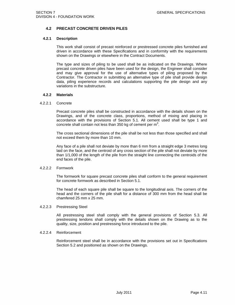
SECTION 7 GENERAL SPECIFICATIONS DIVISION 4 - FOUNDATION WORK
July 2011 Page 4.11
4.2 PRECAST CONCRETE DRIVEN PILES
4.2.1 Description
This work shall consist of precast reinforced or prestressed concrete piles furnished and driven in accordance with these Specifications and in conformity with the requirements shown on the Drawings or elsewhere in the Contract Documents. The type and sizes of piling to be used shall be as indicated on the Drawings. Where precast concrete driven piles have been used for the design, the Engineer shall consider and may give approval for the use of alternative types of piling proposed by the Contractor. The Contractor in submitting an alternative type of pile shall provide design data, piling experience records and calculations supporting the pile design and any variations in the substructure.
4.2.2 Materials
4.2.2.1 Concrete
Precast concrete piles shall be constructed in accordance with the details shown on the Drawings, and of the concrete class, proportions, method of mixing and placing in accordance with the provisions of Section 5.1. All cement used shall be type 1 and concrete shall contain not less than 350 kg of cement per m3. The cross sectional dimensions of the pile shall be not less than those specified and shall not exceed them by more than 10 mm. Any face of a pile shall not deviate by more than 6 mm from a straight edge 3 metres long laid on the face, and the centroid of any cross section of the pile shall not deviate by more than 1/1,000 of the length of the pile from the straight line connecting the centroids of the end faces of the pile.
4.2.2.2 Formwork
The formwork for square precast concrete piles shall conform to the general requirement for concrete formwork as described in Section 5.1. The head of each square pile shall be square to the longitudinal axis. The corners of the head and the corners of the pile shaft for a distance of 300 mm from the head shall be chamfered 25 mm x 25 mm.
4.2.2.3 Prestressing Steel
All prestressing steel shall comply with the general provisions of Section 5.3. All prestressing tendons shall comply with the details shown on the Drawing as to the quality, size, position and prestressing force introduced to the pile.
4.2.2.4 Reinforcement
Reinforcement steel shall be in accordance with the provisions set out in Specifications Section 5.2 and positioned as shown on the Drawings.

SECTION 7 GENERAL SPECIFICATIONS DIVISION 4 - FOUNDATION WORK
July 2011 Page 4.12
4.2.3 Production of Piles
4.2.3.1 Casting
Square piles shall be cast in a horizontal position. Special care shall be taken to place the concrete so as to produce a pile free from any air pockets, honeycombing or other defect. Concrete shall be placed continuously and shall be compacted by vibrating or by other means satisfactory to the Engineer. The forms shall be slightly overfilled, the surplus concrete screeded off, and the top surfaces finished to a uniform, even texture similar to that produced by the forms. Piles may only be constructed in separate shorter elements with the approval of the Engineer. Joints made after casting and/or stressing shall be at least as strong as the piles themselves in every respect.
4.2.3.2 Tensioning Procedure (Prestressed Piles Only)
Tensioning shall be carried out only in the presence of the Engineer, or his representative, unless otherwise approved in writing. As used here the word “tendon” shall be defined as any single prestressing element used to apply prestressed forces to the concrete. For pretensioning this shall be each strand or straight wire. All tendons to be stressed in a group shall be brought to a uniform tension of approximately 500 kilograms per tendon prior to being given their full tension. After this initial stressing the group shall be stressed to a total tension as required on the Drawings by means of hydraulic jacks or other approved appliances equipped with gauges graduated to read directly to 1% of the total load applied, and calibrated to measure accurately the stress induced in the steel. This induced stress shall be measured by elongation of the tendons and checked by gauge pressure. The results obtained shall be within 5% of each other. Means shall be provided for measuring the elongation to an accuracy of one millimetre in twenty metres of length between jacking heads. In the event of apparent discrepancies of more than five percent between stresses indicated by gauge pressure and elongation, the entire operation shall be checked carefully and the source of error determined and corrected before proceeding further. Independent references shall be established adjacent to each anchorage to indicate any yielding or slippage that may occur between the time of initial stressing and final release of the tendons.
4.2.3.3 Curing
Curing of the concrete shall be commenced prior to the formation of surface shrinkage cracks and as the concrete has hardened sufficiently to prevent injury. Curing shall conform to the requirements of Section 5.1.
4.2.3.4 Release (Pretensioned Piles Only)
For precast pretensioned members the tendon stress shall be maintained between anchorages until the concrete has reached a compressive strength equal to the “Transfer Strength” specified on the Drawings. After strength requirements are attained, the tension in the tendons shall be gradually and simultaneously released and the tendons cut off as required in such a way as to prevent shock. It shall be the Contractor's responsibility to transfer the prestress safely and to the Engineer's satisfaction in all respects.

SECTION 7 GENERAL SPECIFICATIONS DIVISION 4 - FOUNDATION WORK
July 2011 Page 4.13
A recess shall be cut at the ends of piles around each tendon to allow cutting off the tendon and filling the recess with grout so that the cover to the end of the tendon is not less than 20 mm.
4.2.3.5 Finishing
Piles shall present a true, smooth, even surface free from any surface blemishes and true to the dimensions shown on the Drawings, within the tolerance limits.
4.2.3.6 Marking of Piles
After a pile has been cast, the date of casting, reference number, length and, where appropriate, the prestressing force shall be clearly inscribed on the top surface of the pile and also clearly and legibly marked on the head of the pile. In addition, each pile shall be marked at intervals of 250 mm along the top 3 metres of its length before being driven.
4.2.3.7 Handling and Storage of Piles
The method and sequence of lifting, handling, transporting and storing piles shall be such that the piles are not damaged. The lifting point of each size of pile shall be proposed by the Contractor with supporting calculations for approval of the Engineer which verifies the pile will not be damaged during lifting, handling, transporting and storage. During transport and storage, piles shall be stored on adequate supports located under the lifting points of the piles. Concrete shall at no time be subjected to loading, including its own weight, which will induce a compressive stress in it exceeding one third of its strength. For this purpose the assessment of the strength of the concrete and of the stresses produced by the loads shall be subject to the agreement of the Engineer. All piles within a stack shall be in groups of the same length. Packings of uniform thickness shall be provided between piles at the lifting points.
4.2.3.8 Spliced Piles
Where the Drawings do not detail any splices in piles, the Contractor may adopt spliced piles provided details of the splicing method and drawings are submitted to the Engineer for approval prior to the manufacture of the piles.
4.2.4 Driving Piles
4.2.4.1 Strength of Piles
Piles shall not be driven until the concrete has achieved the specified 28 day strength. 4.2.4.2 Leaders and Trestles
At all stages during driving and until incorporation in the superstructure, the pile shall be adequately supported and restrained by means of leaders, or other guide arrangements to maintain position and alignment and to prevent buckling. These arrangements shall be such that damage to the pile does not occur. Leaders shall be of sufficient length to make the use of followers unnecessary.
4.2.4.3 Driving Equipment

SECTION 7 GENERAL SPECIFICATIONS DIVISION 4 - FOUNDATION WORK
July 2011 Page 4.14
Before any piling work is commenced the Contractor shall submit to the Engineer full details of the pile driving equipment and the method he intends to use in carrying out the work. For special types of piling, driving head mandrels, or other devices in accordance with requirements shall be provided so that piles may be driven without injury. The driving equipment shall be of a type which assures that the energy needed to penetrate the pile to the required depth is transmitted to the pile head without damaging the pile. Efficiency factor of the hammer, i.e. the relation between the theoretical energy developed by the hammer and the energy submitted to the pile, shall be minimum 0.7. Piles shall be driven with steam, air, diesel or gravity hammers. When diesel hammers are used, they shall be calibrated by load tests if necessary. When gravity hammers are used for driving concrete piles, the drop of the hammer shall not exceed 1 metre and the hammer shall have a weight of not less than 80% of the weight of the pile and the driving head. The fall shall be regulated so as to prevent injury to the pile. The minimum energy developed by other types of hammers shall be the same as specified for gravity hammers.
4.2.4.4 Driving Procedure and Redrive Checks
Each pile shall be driven continuously until the specified or approved set and/or depth has been reached, except that the Engineer may permit the suspension of driving if he is satisfied that the rate of penetration prior to the cessation of driving will be substantially re-established on its resumption or if he is satisfied that the suspension of driving is beyond the control of the Contractor. A follower (long dolly) shall not be used. The Contractor shall inform the Engineer without delay if an unexpected change in driving characteristics is noted. A detailed record of the driving resistance over the full length of the nearest available pile shall be taken if required. At the start of work and in a new area or section, sets shall be taken at intervals during the last 3 metres of the driving to establish the behaviour of the piles. The Contractor shall give adequate notice and provide all facilities to enable the Engineer to check driving resistances. A set shall be taken only in the presence of the Engineer unless otherwise approved. Redrive checks, if required, shall be carried out to an approved procedure.
4.2.4.5 Final Set
The final set of each pile shall be recorded either as the penetration in millimetres per 10 blows or as the number of blows required to produce a penetration of 250 mm. When a final set is being measured, the following requirements shall be met: a) The exposed part of the pile shall be in good condition without damage or distortion. b) The dolly and packing, if any, shall be in sound condition. c) The hammer blow shall be in line with the pile axis and the impact surfaces shall be
flat and at right angles to the pile and hammer axis. d) The hammer shall be in good condition and operating correctly. e) The temporary compression of the pile shall be recorded if required.
4.2.4.6 Driving Sequence and Risen Piles

SECTION 7 GENERAL SPECIFICATIONS DIVISION 4 - FOUNDATION WORK
July 2011 Page 4.15
Piles shall be driven in an approved sequence to minimise the detrimental effects of heave and lateral displacement of the ground. When required, levels and measurements shall be taken to determine the movement of either the ground or of any pile which results from the driving process. When a pile has risen as a result of adjacent piles being driven, the Contractor shall submit to the Engineer his proposals for correcting this and the avoidance of it in subsequent work.
4.2.4.7 Jetting
Water jetting shall not be allowed. Continuous vibratory percussive methods shall be used to drive a pile to both its design depth as well as the required set where the upper strata affords high resistance to driving.
4.2.4.8 Length of Piles
The lengths of the piles shown on the Drawings are based on information which has been obtained from a site investigation prior to the driving of test piles. Before pile lengths are finally settled, the Contractor shall construct to the lengths shown on the Drawings such pilot piles as may be found necessary and these piles shall be driven in the positions specified by the Engineer who shall be notified in advance of the driving. The Contractor shall furnish the Engineer daily with a detailed record of the pilot piles for the full depth of driving. After attaining the approved set, driving shall be continued until the Engineer directs that it shall cease. Driving of pilot piles beyond the point at which the approved set is obtained shall be called for to demonstrate that driving resistance continues to increase. The Contractor shall then provide the remainder of the piles. In determining the lengths of piles the Contractor shall base his order list on the lengths assumed to remain in the completed structure. The Contractor at his own expense can increase the lengths to provide for fresh heading and for such lengths as may be necessary to suit his method of operation. Reference is made to Section 4.4 with regard to load tests on selected pilot piles.
4.2.4.9 Repair or Damaged Pile Heads
When repairing the head of a pile, the head shall be cut off square at sound concrete, and all loose particles shall be removed by wire brushing, followed by washing with water. If the pile is to be subjected to further driving, the head shall be replaced with concrete of an approved grade. If the driving of a pile has been accepted but sound concrete of the pile is below the cut-off level, the pile shall be made good to the cut-off level with concrete of a grade not inferior to that of the concrete of the pile. Repaired piles shall not be driven until the added concrete has reached the specified characteristic strength of the concrete of the pile.

SECTION 7 GENERAL SPECIFICATIONS DIVISION 4 - FOUNDATION WORK
July 2011 Page 4.16
4.2.4.10 Cut off and Extension
Prestressed concrete piles shall be cut off at such elevation that they shall extend into the cap or footing as indicated on the Drawings. In the case of hollow core piles starter bars shall be cast into the core at the top of the piles and extended into the cap or footing, all as shown on the Drawings. Extensions to prestressed concrete piles shall generally not be permitted, unless a provision for lengthening prestressed piles was incorporated at the time of manufacture. Any method for lengthening shall be such that joints are capable of taking safely the stresses during driving and under load.
4.2.4.11 Damage to Adjacent Structures and Services
The Contractor will take all necessary precautions to avoid damage to any adjacent structures and services. If during the execution of the work damage is, or is likely to be, caused to any adjacent structures or services, the Contractor shall submit to the Engineer his proposals for repair or avoidance of such damage.
4.2.4.12 Records
The Contractor shall keep records as indicated below of the installation of each pile and shall submit two signed copies of these records to the Engineer not later than noon of the next working day after the pile is installed. The signed records shall form a record of the work. The following data are required: a) Pile location b) Pile reference number c) Pile type d) Nominal cross-sectional dimensions or diameter e) Length of preformed pile f) Date and time of driving or redriving g) Ground level at commencement of installation of pile h) Working level i) Pile toe level j) Type, weight, drop and mechanical condition of hammer and equivalent
information for other equipment k) Number and type of packing used and type and condition of dolly used during
driving the pile l) Set of pile in mm per 10 blows or number of blows per 250 mm of penetration m) If required, the sets taken at intervals during the last 3 metres of driving n) If required, temporary compression of ground and pile from time of a marked
increase in driving resistance until pile reaches its final level o) All information regarding obstructions delays and other interruptions to the
sequence of work
4.2.5 Tolerances
4.2.5.1 Setting Out
Setting out shall be carried out from the main grid lines of the proposed structure. Before installation of the pile, the pile position shall be agreed with the Engineer and marked with suitable identifiable pins or markers.
4.2.5.2 Position
For a pile cut off at or above ground level the maximum permitted deviation of the pile centre from the centre point shown on the setting out drawing shall be 75 mm in any

SECTION 7 GENERAL SPECIFICATIONS DIVISION 4 - FOUNDATION WORK
July 2011 Page 4.17
direction. An additional tolerance for a pile head cut off below ground level shall be permitted in accordance with Sections 4.2.5.3 and 4.2.5.4.
4.2.5.3 Verticality
The maximum permitted deviation of the finished pile from the vertical shall be 1 in 50.
4.2.5.4 Rake
The piling rig shall be set and maintained to attain the required rake. The maximum permitted deviation of the finished pile from the specified rake shall be 1 in 25.
4.2.6 Defective Piles
The procedure of driving the piles shall not subject them to excessive and undue abuse producing crushing and spalling of the concrete or deformation of the steel. Manipulation of piles to force them into proper position, considered by the Engineer to be excessive, shall not be permitted. Any pile damaged by reason of internal defects, or by improper driving or driven out of its proper location or driven below the elevation fixed by the plans or by the Engineer, shall be corrected at the Contractor’s expense by one of the following methods approved by the Engineer for the pile in question: 1) The pile shall be withdrawn and replaced by a new and if necessary, a longer pile. 2) A second pile shall be driven adjacent to the defective or low pile. 3) The pile shall be spliced or built up as otherwise provided herein or a sufficient portion
of the footing extended to properly embed the pile.
4.2.7 Measurement
The unit of measurement shall be the linear metre of pile furnished, driven and accepted in the structure. The pay lengths of the satisfactorily driven piles shall be measured from the toe to the cut off. Cut off lengths shall not be measured for payment. Reinforcement steel shall be measured in accordance with Specifications Section 5.2.4.
4.2.8 Payment
Precast concrete driven piles shall be paid for at the Contract unit rate per linear metre. The rate shall constitute full compensation for all materials but excluding reinforcement, which shall be paid for separately. The rate shall also include all shoes, equipment, hardware, formwork etc., driving, cutting off, lengthening and splicing, welding and coupling and all related tools, rigs, cranes, boilers, hammers, leaders, labour and other incidental equipment and work. Payment for precast concrete driven pilot piles (see Section 4.4.1.2(e) for definition of pilot pile), completed and accepted, shall be made at the Contract unit price per linear metre for providing piles of the size specified. When pilot piles are incorporated in the foundation as working piles, no additional payment shall be made for the piles. Payment for reinforcement steel shall be at the Contractor’s rates per tonne for mild steel and high yield deformed steel bars. No payment shall be made for unauthorised, defective, unsound or unsatisfactorily driven piles or for any costs incurred by the Contractor for such piles.

SECTION 7 GENERAL SPECIFICATIONS DIVISION 4 - FOUNDATION WORK
July 2011 Page 4.18
Payment for testing of piles shall be made separately, as detailed in Section 4.4. Pay items shall be: 04/02/01(a) Driven Precast Piles (300mm X 300mm) Linear Metre
04/02/01(b) Driven Precast Piles (350mm X 350mm) Linear Metre
04/02/01(c) Driven Precast Piles (400mm X 400mm) Linear Metre
04/02/02 Driven Precast Pilot Piles Linear Metre (Dimensions as indicated on the Drawings and stated in the Bill of Quantities) 04/02/03 Mild Steel Reinforcing Bars Tonne 04/02/04 High Yield Deformed Steel Reinforcing Bars Tonne

SECTION 7 GENERAL SPECIFICATIONS DIVISION 4 - FOUNDATION WORK
July 2011 Page 4.19
4.3 PRECAST CONCRETE UNITS FOR RIVER TRAINING AND RETAINING STRUCTURES
4.3.1 Description
This work shall consist of furnishing and placing all precast members of retaining and river training structures and anchor arrangements, all in accordance with these Specifications and in conformity with the requirements on the Drawings or of other parts of the Contract Documents. The precast structures consist essentially of precast and driven “I” shaped concrete piles (King Posts) laterally supporting precast concrete planks. The king posts may be laterally anchored through tie bars to raker piles.
4.3.2 Materials
The king posts and raker piles shall conform to the requirements of Section 4.2.2. The precast concrete planks shall be constructed in accordance with the details shown on the Drawings, and in accordance with Sections 5.1 and 5.2. Cement used shall be type 1.
4.3.3 Construction Methods
4.3.3.1 King Post & Anchor Piles
All production and construction methods for king posts and anchor piles shall conform to Sections 4.2.3 and 4.2.4 except that load testing shall not normally be required.
4.3.3.2 Precast Planks
The precast planks shall be placed between the king posts as shown on the Drawings. The planks shall be excavated or driven down to the levels indicated on the Drawings or as otherwise directed. In this connection it may be necessary to clear up the bed to the prescribed level and make local excavations along the planks as they are lowered. The method of placing the planks shall be agreed with the Engineer.
4.3.4 Tolerances
The horizontal position of the king posts after being driven shall not deviate from the correct position more than +10 mm perpendicular to the line of the wall and +10 mm in the direction of the wall. The precast planks in between the piles are designed to allow for a longitudinal tolerance of king post position of +10 mm. If the Contractor during construction establishes that the above tolerance is too small, the Engineer may accept minor changes in the tolerance. Such changes will require corresponding changes in plank sizes.
4.3.5 Measurement
King posts shall be measured by linear meter in accordance with Section 4.2.7. No distinction shall be made for different sizes or shapes of king posts which shall be as shown on the Drawings. Precast planks shall be measured by square meter of plank used. Raker piles shall be measured by linear metre in accordance with Section 4.2.7. No distinction shall be made for different sizes or rakes of raker piles which shall be as shown on the Drawings. Tie bars shall not be measured separately but are deemed included in the rate for raker piles.

SECTION 7 GENERAL SPECIFICATIONS DIVISION 4 - FOUNDATION WORK
July 2011 Page 4.20
Reinforcement steel in king posts and raker piles shall be measured in accordance with Specifications Section 5.2.4. Reinforcement steel in precast planks shall not be measured separately.
4.3.6 Payment
The Contractor’s rates for king posts and raker piles will constitute full compensation for the supply of all materials excluding reinforcement steel, which shall be paid for separately. The rates shall also include handling, placing and all other related works. The Contractor’s rate for precast planks will constitute full compensation for the supply of all materials including reinforcement steel, handling, placing and all other related works. Stone protection, if required, will be measured and paid for separately in accordance with Section 6. Pay items shall be: 04/03/01 King Post Linear Metre 04/03/02 Raker Piles (including Tie Bars) Linear Metre 04/03/03 Precast Planks (including Reinforcement Steel) Square Metre 04/03/04 Mild Steel Reinforcing Bars to King Posts Tonne and Raker Piles 04/03/05 High Yield Deformed Steel Reinforcing Bars Tonne to King Posts and Raker Piles
4.3.7 PILE INTEGRITY TEST
4.3.7.1 Description
Pile Integrity test is to be performed by the Procuring Entity through BRRL or Bridge unit Professionals or any reputed organization appointed by the Engineer on a number of constructed working piles at the location of each abutment and pier position of a structure to verify the integrity of the installed piles. The apparatus for the Integrity Test shall be selected and arranged by the testing organization. Tests shall be carried out only under the direction of experienced and competent professionals conversant with the test equipment and test procedure.
4.3.7.2 Test procedure
All piles are to be selected for testing. With the permission from the Design unit selected piles can be tested. The contractor shall provide detailed records as recorded during installation of each pile which is to be tested. The contractor shall cut down all pile heads at the cut off level or otherwise prepare the piles for testing as required by the Engineer. The pile head shall be formed to give plane surface which is normal to the axis of the pile. The reinforcement of the pile shall be bent in such a way to ease the testing.

SECTION 7 GENERAL SPECIFICATIONS DIVISION 4 - FOUNDATION WORK
July 2011 Page 4.21
4.3.7.3 Results of Testing
Pile Integrity test or sonic test is a quick method to check the continuity of pile shape and size up to desired level. This method detects pile defects like cracks, Breaking, Necking, soil intrusion and variation of pile shape. The final length can also be measured indirectly. If any pile after Integrity test is found unsatisfactory in the opinion of the Engineer for utilization in the structure, the pile shall be replaced as suggested by the design unit and directed by the Engineer/Project Manager. All extra expanses shall be borne by the contractor and payment shall be made in accordance with clause 4.1.3.11 of these specifications.
4.3.7.4 Measurement
The unit of measurement shall be number of pile tested.
4.3.7.5 Payment
The test performed in the number of piles shall be paid for at the rate charged by the approved testing organization. The rate shall constitute full compensation for all materials, equipments and labour for test purpose. The payment shall be made by the contractor to the test performer and the amount shall be reimbursed to the contractor by the procuring Entity from the provisional sum as indicated in the bill of quantities. The bill for integrity test shall not be paid separately to the contractor because it is already included in the item number 4.1.5.

SECTION 7 GENERAL SPECIFICATIONS DIVISION 4 - FOUNDATION WORK
July 2011 Page 4.22
4.4 PILE TEST LOADING
4.4.1 Descriptions
4.4.1.1 General
This Section deals with the testing of a pile by the application of an axial load or force. It covers vertical piles tested in compression.
4.4.1.2 Definitions
A) Allowable Load The load which may be safely applied to a pile after taking into account its ultimate bearing capacity, negative friction, pile spacing, overall bearing capacity of the ground below and allowable settlement. B) Compression Pile A pile which is designed to resist an axial force such as would cause it to penetrate further into the ground. C) Kentledge The dead weight used in a loading test. D) Maintained Load Test A loading test in which each increment of load is held constant either for a defined period of time or until the rate of movement (settlement or uplift) falls to a specified value. E) Pilot Pile A pile installed before the commencement of the main piling works or a specific part of the works for the purpose of establishing the suitability of the chosen type of pile and for confirming its design, dimensions and bearing capacity. Pilot piles may be utilised as working piles, subject to the Engineer’s approval. F) Proof Load A load applied to a selected pile to confirm that it is suitable for the load at the settlement specified. A proof load should not normally exceed 200% of the working load on a pile except in circumstances where Special Provisions are provided for the testing of precast piles driven to a set. In these circumstances, 300% is specified. G) Reaction System The arrangement of kentledge, piles, anchors or rafts that provides a resistance against which the pile is tested. H) Tension Pile A pile which is designed to resist an axial force such as would cause it to be extracted from the ground. I) Test Pile

SECTION 7 GENERAL SPECIFICATIONS DIVISION 4 - FOUNDATION WORK
July 2011 Page 4.23
Any pile to which a test loading is, or is to be, applied. J) Ultimate Bearing Capacity The load at which the resistance of the soil becomes fully mobilised. K) Working Load The load which the pile is designed to carry. L) Working Pile One of the piles forming the foundation of a structure.
4.4.2 Supervision
All tests shall be carried out only under the direction of an experienced and competent supervisor conversant with the test equipment and test procedure. All personnel operating the test equipment shall have been trained in its use.
4.4.3 Safety Precautions
4.4.3.1 General
When preparing for, conducting and dismantling a pile test the Contractor shall carry out the requirement of the various regulations and other statutory instruments that are applicable to the work for the provision and maintenance of safe working conditions, and shall in addition make such other provision as may be necessary to safeguard against any hazards that are involved in the testing or preparations for testing.
4.4.3.2 Kentledge
Where kentledge is used the Contractor shall construct the foundations for the kentledge and any cribwork, beams or other supporting structure in such a manner that there will not be differential settlement, bending or deflexion of an amount that constitutes a hazard to safety or impairs the efficiency of the operation. The kentledge shall be adequately bonded, tied or otherwise held together to prevent it falling apart, or becoming unstable because of deflection of the supports. The weight of kentledge shall be greater than the maximum test load and if the weight is estimated from the density and volume of the constituent materials an adequate factor of safety against error shall be allowed.
4.4.3.3 Tension Piles and Ground Anchors
Where tension piles or ground anchors are used the Contractor shall ensure that the load is correctly transmitted to all the tie rods or bolts. The extension of rods by welding shall not be permitted unless it is known that the steel will not be reduced in strength by welding. The bond stresses of the rods in tension shall not exceed normal permissible bond stresses for the type of steel and grade of concrete used.

SECTION 7 GENERAL SPECIFICATIONS DIVISION 4 - FOUNDATION WORK
July 2011 Page 4.24
4.4.3.4 Testing Equipment
In all cases the Contractor shall ensure that when the hydraulic jack and load measuring device are mounted on the pile head the whole system shall be stable up to the maximum load to be applied. Means shall be provided to enable dial gauges to be read from a position clear of the kentledge stack or test frame so that failure in any part of the system due to overloading, buckling, loss of hydraulic pressure will not constitute a hazard to personnel. The hydraulic jack, pump, hoses, pipes, couplings and other apparatus to be operated under hydraulic pressure shall be capable of withstanding a test pressure of 1.5 times the maximum working pressure without leaking. The maximum test load or test pressure expressed as a reading on the gauge in use shall be displayed and all operators shall be made aware of this limit.
4.4.4 Construction of a Pilot Pile to be Test Loaded
4.4.4.1 Notice of Construction
The Contractor shall give the Engineer at least 48 hours notice of the commencement of construction of any pilot pile, which is to be test loaded.
4.4.4.2 Method of Construction
Each pilot test pile shall be constructed in a manner similar to that to be used for the construction of the working piles, and by the use of similar equipment and materials. Any variation shall only be permitted with prior approval. Extra reinforcement and concrete of increased strength shall be permitted in the shafts of pilot piles at the discretion of the Engineer.
4.4.4.3 Boring or Driving Record
For each pilot pile which is to be tested a detailed record of the soils encountered during boring, or of the progress during driving shall be made and submitted to the Engineer daily not later than noon on the next working day.
4.4.4.4 Cut-Off Level
The pile shaft shall terminate at the normal cut-off level, or at a level required by the Engineer. The pile shaft shall be extended where necessary above the cut-off level of working piles so that gauges and other apparatus to be used in the testing process are not damaged by water or falling debris.
4.4.4.5 Pile Head for Compression Tests
For a pile that is tested in compression, the pile head or cap shall be formed to give a plane surface which is normal to the axis of the pile, sufficiently large to accommodate the loading and settlement-measuring equipment and adequately reinforced or protected to prevent damage from the concentrated application of load from the loading equipment.
4.4.5 Preparation of a Working Pile to be Tested
If a test is required on a working pile the Contractor shall cut down or otherwise prepare the pile for testing as required by the Engineer in accordance with Sections 4.4.4.4 and 4.4.4.5.

SECTION 7 GENERAL SPECIFICATIONS DIVISION 4 - FOUNDATION WORK
July 2011 Page 4.25
4.4.6 Reaction Systems
4.4.6.1 Compression Tests
Compression tests shall be carried out using kentledge, tension piles or specially constructed anchorages. Where kentledge is to be used, it shall be supported on cribwork disposed around the pile head so that its centre of gravity is on the axis of the pile. The bearing pressure under supporting cribs shall be such as to ensure stability of the kentledge stack. Kentledge shall not be carried directly on the pile head, except when directed by the Engineer.
4.4.6.2 Working Piles
Where working piles are used as reaction piles their movement shall be measured to within an accuracy of 0.5 mm.
4.4.6.3 Spacing
Where kentledge is used for loading vertical piles in compression, the distance from the edge of the test pile to the nearest part of the crib supporting the kentledge stack in contact with the ground shall be not less than 1.3 metres. The centre to centre spacing of vertical reaction piles, including working piles used as reaction piles, from a test pile shall be not less than three times the diameter of the test pile or the reaction piles or 2 metres, whichever is the greatest.
4.4.6.4 Adequate Reaction
The size, length and number of the piles or anchors, or the area of the rafts, shall be adequate to transmit the maximum test load to the ground in a safe manner without excessive movement or influence on the test pile.
4.4.6.5 Care of Piles
The method employed in the installation of any reaction piles, anchors or rafts shall be such as to prevent damage to any test pile or working pile.
4.4.6.6 Loading Arrangement
The loading arrangement used shall be designed to transfer safely to the test pile the maximum load required in testing. Full details shall be submitted to the Engineer prior to any work related to the testing process being carried out on the Site.
4.4.7 Equipment for Applying Load
The equipment used for applying load shall consist of one or more hydraulic rams or jacks with the total capacity of the jacks being at least equal to the required maximum load. The jack or jacks shall be arranged in conjunction with the reaction system to deliver an axial load to the test pile. The complete system shall be capable of transferring the maximum load required for the test.
4.4.8 Measurement of Load
Suitable approved measuring devices for determining the load on the pile shall be supplied by the Contractor. Certificates of calibration shall be supplied to the Engineer. In addition, large diameter (i.e. exceeding 1.2 metre) test piles shall be instrumented at 5 different depths to measure the load distribution along the piles. The instrumentation shall

SECTION 7 GENERAL SPECIFICATIONS DIVISION 4 - FOUNDATION WORK
July 2011 Page 4.26
consist of both a mechanical system and strain gauges for measuring the pile deformation. The mechanical system shall consist of 6 mm steel rods or high tensile steel wires gauge No. 23, placed in steel tubes down to the various depths, and connected to dial gauges at the top. The strain gauges shall be of a stable type, wholly protected by a steel capsule. They shall be welded to the steel reinforcement, 2 gauges at each depth. The Engineer shall approve the type of gauges to be used and other details on the instrumentation.
4.4.9 Adjustability of Loading Equipment
The loading equipment shall be capable of adjustment throughout the test to obtain a smooth increase of load or to maintain each load constant at the required stages of a maintained loading test.
4.4.10 Measuring Movement of Pile Heads
4.4.10.1 General
In a maintained load test movement of the pile head shall be measured by two of the methods as described below. One method for settlement measurements, the other method for control.
4.4.10.2 Levelling Method
An optical or any other levelling method by reference to an external datum may be used. Where a level and staff are used, the level and scale of the staff shall be chosen to enable readings to be made to within an accuracy of 0.5 mm. A scale attached to the pile or pile cap may be used instead of a levelling staff. At least two datum points shall be established on permanent objects or other well-founded structures, or deep datum points shall be installed. Each datum point shall be situated so that only one setting up of the level is needed. No datum point shall be affected by the test loading or other operations on the site. Where another method of levelling is proposed this shall be approved in writing.
4.4.10.3 Independent Reference Frame
An independent reference frame may be set up to permit measurement of the movement of the pile. The supports for the frame shall be founded in such a manner and at such a distance from the test pile, kentledge support cribs, reaction piles, anchorages and rafts that movements of the ground in the vicinity of the equipment do not cause movement of the reference frame during the testing. Check observations of any movements of the reference frame shall be made and a check shall be made of the movement of the pile head relative to an external datum during the progress of the test. In no case shall the supports be less than three test pile diameters or 2 metres, whichever is the greater, from the centre of the test pile. The measurement of pile movement shall be made by two dial gauges rigidly mounted on the reference frame that bear on surfaces normal to the pile axis fixed to the pile cap or head. Alternatively the gauges may be fixed to the pile and bear on surfaces on the reference frame. The dial gauges shall be placed in diametrically opposed positions and be equidistant from the pile axis. The dial gauges shall enable readings to be made to within an accuracy of 0.1 mm. The reference frames shall be protected from sun and wind.

SECTION 7 GENERAL SPECIFICATIONS DIVISION 4 - FOUNDATION WORK
July 2011 Page 4.27
4.4.10.4 Other Methods
The Contractor may submit for approval any other method for measuring the movement of pile heads.
4.4.11 Protection of Testing Equipment
4.4.11.1 Protection from Weather
Throughout the test period all equipment for measuring load and movement shall be protected from the weather.
4.4.11.2 Prevention of Disturbance
Construction equipment and persons who are not involved in the testing process shall be kept at a sufficient distance from the test to avoid disturbance to the measurement apparatus.
4.4.12 Supervision
4.4.12.1 Notice of Test
The Contractor shall give the Engineer at least 24 hours notice of the commencement of the test.
4.4.12.2 Records
During the progress of a test, the testing equipment and all records of the test as required in Section 4.4.14.2 shall be available for inspection by the Engineer.
4.4.13 Test Procedure
4.4.13.1 Proof Test by Maintained Load Test
The maximum load, which shall be applied in a proof test, is shown on the Drawings. The loading and unloading shall be carried out in stages as shown in Table 4.4-1 or as required by the Engineer. Following each application of an increment of load the load shall be held for not less than the period shown in Table 4.4-1 or until the rate of settlement is less than 0.25 mm/hour and is slowing down. The rate of settlement shall be calculated from the slope of the curve obtained by plotting values of settlement versus time and drawing a smooth curve through the points. Each stage of unloading shall proceed after the expiry of the period shown in Table 4.4-1. For any period when the load is constant, time and settlement shall be recorded immediately on reaching the load and at approximately 15 minute intervals for 1 hour, at 30 minute intervals between 1 hour and 4 hours, and at 1 hour intervals between 4 hours and 12 hours after the application of the increment of load. The Engineer may require that the full loading, or any portion of the loading, be maintained on the pile for periods longer than shown in Table 4.4-1. Table 4.4-1
Loading Sequence Load as Percentage of Working Load Minimum Time of

SECTION 7 GENERAL SPECIFICATIONS DIVISION 4 - FOUNDATION WORK
July 2011 Page 4.28
Bored Piles Driven Piles Holding Load 25 50 1 hour 50 100 1 hour 75 125 1 hour 100 150 1 hour 75 125 10 minutes 50 100 10 minutes 25 50 10 minutes 0 0 1 hour 100 150 6 hours 125 200 1 hour 150 250 6 hours 175 275 1 hour 200 300 24 hours Proof Load 175 275 10 minutes 150 250 10 minutes 125 225 10 minutes 100 200 10 minutes 75 150 10 minutes 50 100 10 minutes 25 50 10 minutes 0 0 1 hour
4.4.14 Presentation of Results
4.4.14.1 Results to be Submitted
Results shall be submitted as: a) A summary in writing to the Engineer, unless otherwise directed, within 24 hours of
the completion of the test, which shall give for a proof test by maintained load for each stage of loading, the period for which the load was held, the load and the maximum settlement or uplift recorded.
b) The completed schedule of recorded data as in Section 4.4.14.2 within seven days of
the completion of the test.
4.4.14.2 Schedule of Recorded Data
The Contractor shall provide information about the tested pile in accordance with the following schedule where applicable. A) General 1) Site location 2) Contract identification 3) Proposed structure 4) Date of test B) Pile Details

SECTION 7 GENERAL SPECIFICATIONS DIVISION 4 - FOUNDATION WORK
July 2011 Page 4.29
1) Identification (number and location of the test pile) 2) Ground level at pile position 3) Head level as which test load is applied 4) Type of pile 5) Length in ground 6) Level in ground 7) Level of toe 8) Details of Permanent casing C) Installation Details 1) Dates and times of boring, driving and concreting of test pile and adjacent piles 2) Date and time of casting concrete 3) Driven length of pile or temporary casing at final set 4) Hammer type, size or weight 5) Dolly and packing, type and condition before and after driving 6) Driving log (depth, blows per 250 mm, interruptions or breaks in driving) 7) At final set and at redrive set, for drop or single acting hammers, the length of the
drop or stroke, for diesel hammers the length of the stroke and the blows per minutes, for double-acting hammers the number of blows per minute
8) Condition of pile head or temporary casing after driving D) Test Procedure 1) Weight of kentledge 2) Tension pile, ground anchor or compression pile details 3) Plan of test arrangement showing position and distances of kentledge supports, rafts, tension or compression piles and reference frame to test pile 4) Jack capacity 5) Method of Load measurement 6) Method(s) of penetration measurement 7) Relevant dates and times

SECTION 7 GENERAL SPECIFICATIONS DIVISION 4 - FOUNDATION WORK
July 2011 Page 4.30
E) Test Results 1) In tabular form 2) In graphical form: loads plotted against movements and time
4.4.15 Completion of a Test
4.4.15.1 Measuring Equipment
On completion of a test all equipment and measuring devices shall be dismantled, checked and either stored so that they are available for use in further tests or removed from the Site.
4.4.15.2 Kentledge
Kentledge and its supporting structure shall be removed from the test pile and stored so that they are available for use in further tests or removed from the Site.
4.4.15.3 Temporary Piles
On completion of a preliminary test, temporary tension piles shall be cut off below ground level, removed from the Site and the ground made good with approved material as specified.
4.4.16 Measurement and Payment
Load tests on large diameter (i.e. exceeding 1.2 metre) cast in place bored piles shall normally be carried out on working piles using other working piles as anchor piles. The test pile and anchor piles will be paid for at the normal rates for working piles as provided in Section 4.1. Separate payments will be made for carrying out each load test, individual rates shall be provided for different proof loads, which are specified in the Bill of Quantities. Payment for load tests on large diameter cast in place bored piles shall include provision of special instrumentation to test piles, anchor bars to reaction piles, provision of all testing equipment, carrying out of the tests, dismantling of equipment and removal from site, breaking out pile heads etc. in accordance with the requirements for working piles, preparation of all reports etc. Load tests on pilot driven piles shall normally be carried out using temporary anchor piles or kentledge. The pilot pile will be paid for at the rates provided for pilot piles in Section 4.2. Separate payment shall not be made for anchor piles. Separate payments will be made for carrying out each load test and individual rates shall be provided for different proof loads, which are specified in the Bill of Quantities. Payment for load tests on pilot driven piles shall include provision of anchor piles or kentledge, provision of all test equipment, carrying out of the tests, dismantling of equipment and removal from site, cutting off below level of temporary anchor piles, preparation of all reports etc. Load tests on pilot cast in place piles, less than 1.2 metre diameter, shall normally be carried out using temporary anchor piles or kentledge. The pilot pile will be paid for at the rates provided for pilot piles in Section 4.1. Separate payment shall not be made for anchor piles. Separate payments will be made for carrying out each load test and individual rates shall be provided for different proof loads, which are specified in the Bill of Quantities. Payment for load tests on pilot piles shall include provision of anchor piles or kentledge, provision of all test equipment, carrying out of the tests, dismantling of equipment and removal from site, cutting off below level of temporary anchor piles, preparation of all reports etc.

SECTION 7 GENERAL SPECIFICATIONS DIVISION 4 - FOUNDATION WORK
July 2011 Page 4.31
Pay items shall be: 04/04/01(a) Load Test on Cast in Place Working Pile Number (Proof load to be specified in BoQ) 50 Ton 04/04/01(b) Load Test on Cast in Place Working Pile Number (For 100 Ton) 04/04/01(c) Load Test on Cast in Place Working Pile Number (For 200 Ton) 04/04/02 Load Test on Cast in Place Pilot Pile Number (Proof load to be specified in BoQ) 04/04/03 Load Test on Pilot Driven Pile Number (Proof load to be specified in BoQ)

SECTION 7 GENERAL SPECIFICATIONS DIVISION 4 - FOUNDATION WORK
July 2011 Page 4.32
4.5 BITUMEN SLIP LAYER FOR PILES
4.5.1 Description
This work shall consist of a bitumen slip layer placed on the upper part of concrete piles before driving. Bitumen slip layer is provisional, and shall be used only if directed by the Engineer. The use of a slip layer to reduce negative skin friction on the piles will be evaluated after completion of pile load tests. The bitumen layer shall be used on the upper part of the pile through soft and medium stiff clay. Any shorter length may be decided by the Engineer. This part of the pile shall be primed and uniformly coated with a bituminous material as specified below. No priming or coating shall be allowed below the designated elevation of the installed pile.
4.5.2 Materials
4.5.2.1 Primer
Before priming, the pile shall be completely clean and dry. The primer shall consist of the relevant bitumen for the slip layer and a petroleum solvent, or RC 250 as decided by the Engineer. The bitumen and the solvent shall be suitably blended to produce a liquid coating which may be applied cold, and which produces a suitable bond between the pile surface and the asphalt enamel. The primer shall have good spraying, brushing and levelling properties and a minimum tendency to produce bubbles during application. It shall be homogeneous and free from water. The amount of primer shall be 0.2 litre/m2, applied with brushing or spraying to achieve a uniform continuous film. The primer shall be allowed to set thoroughly, for minimum 6 hours or more as needed, before the slip layer is applied.
4.5.2.2 Bitumen
The bitumen slip layer shall consist of a straight run bitumen, penetration grade 80-100. The bitumen shall be heated to a liquid state, that is approximately 200°C, and applied by brushing or other approved means. The thickness shall be minimum 3 mm. Special measures such as wrapping sprayed surfaces with suitable paper or plastic sheet shall be taken to prevent the bitumen from flowing and stripping and from damage during handling and storage. During storage the piles shall be protected from sun-heat, and if necessary cooled with spraying of water.
4.5.3 Field Storage and Installation
Precautions shall be taken to prevent damage to the bitumen slip layer during installation as deemed necessary by the Engineer. Piles shall not be placed directly on the ground: wood sleepers shall always be used. The sleepers shall be placed beneath the uncoated end parts. When lifting piles the wire rope should not be in direct contact with the bitumen slip layer.

SECTION 7 GENERAL SPECIFICATIONS DIVISION 4 - FOUNDATION WORK
July 2011 Page 4.33
4.5.4 Measurement
The unit of measurement shall be square meters of pile covered by bitumen slip layer and accepted by the Engineer. Cut off lengths shall not be measured for payment.
4.5.5 Payment
This work measured as provided above shall be paid for at the Contract unit prices per square metre. The unit rate shall constitute full compensation for all materials, equipment and workmanship necessary to provide the slip layer and the protective layer inclusive of protective metal rings if required, and the additional costs incurred during handling and driving of the piles. Payment shall only be made if bitumen slip layer is selected and ordered in writing by the Engineer. Pay item shall be: 04/05/01 Bitumen Slip Layer to Concrete Piles Square Metre

SECTION 7 GENERAL SPECIFICATIONS DIVISION 4 - FOUNDATION WORK
July 2011 Page 4.34
4.6 DRIVEN BULLAH PILES
4.6.1 Description
This work shall consist of providing and driving wooden piles in accordance with these Specifications and in conformity with the requirements of the Drawings or the Engineer’s instructions.
4.6.2 Materials
Bullah piles shall consist of best quality timber; Sal, Sundari, or Garzon. The diameter shall be 200-250 mm and the length shall be such that not less than 4.5 metres of acceptable pile can be driven. Each pile shall be fitted with a metal shoe.
4.6.3 Driving Piles
4.6.3.1 Driving Equipment
Before any piling work is commenced the Contractor shall submit to the Engineer full details of the pile driving equipment and the methods he intends to use in carrying out the work.
4.6.3.2 Leaders and Trestles
At all stage of driving the pile shall be adequately supported and restrained by means of leaders or other guide arrangements to maintain position and alignment. These arrangements shall be such that damage to the pile does not occur.
4.6.3.3 Hammers
Any kind of hammer may be used provided that it is of a type which assures that the energy needed to penetrate the pile to the required depth is transmitted to the pile head without damaging the pile. When gravity hammer are used the drop shall not exceed 1.0 metre. The fall shall be regulated so as to prevent damage to the pile. The efficiency factor of the hammer, i.e., the relationship between the theoretical energy developed by the hammer and the energy transmitted to the pile, shall be a minimum of 0.7.
4.6.3.4 Length of Piles
The length of piles to be driven shall be as shown on the Drawings or as approved or directed by the Engineer. Piles shall be neatly cut off at the specified level.
4.6.3.5 Records
The Contractor shall keep records as indicated below for each pile and submit two signed copies to the Engineer not later that the next working day that a pile is driven. a) Pile Location b) Pile Reference Number c) Pile Type and Diameter d) Date and Time of Driving e) Ground Level f) Details of Hammer and Drop g) Details of any Delay or Interruptions
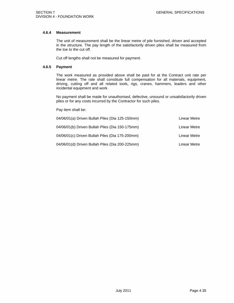
SECTION 7 GENERAL SPECIFICATIONS DIVISION 4 - FOUNDATION WORK
July 2011 Page 4.35
4.6.4 Measurement
The unit of measurement shall be the linear metre of pile furnished, driven and accepted in the structure. The pay length of the satisfactorily driven piles shall be measured from the toe to the cut off. Cut off lengths shall not be measured for payment.
4.6.5 Payment
The work measured as provided above shall be paid for at the Contract unit rate per linear metre. The rate shall constitute full compensation for all materials, equipment, driving, cutting off and all related tools, rigs, cranes, hammers, leaders and other incidental equipment and work. No payment shall be made for unauthorised, defective, unsound or unsatisfactorily driven piles or for any costs incurred by the Contractor for such piles. Pay item shall be: 04/06/01(a) Driven Bullah Piles (Dia 125-150mm) Linear Metre 04/06/01(b) Driven Bullah Piles (Dia 150-175mm) Linear Metre 04/06/01(c) Driven Bullah Piles (Dia 175-200mm) Linear Metre 04/06/01(d) Driven Bullah Piles (Dia 200-225mm) Linear Metre

SECTION 7 GENERAL SPECIFICATIONS DIVISION 4 - FOUNDATION WORK
July 2011 Page 4.36
4.7 Well Foundations
4.7.1 Description
This work shall consist of construction of well foundation, taking it down to the founding level through all kinds of sub-strata, plugging the bottom, filling the inside of the well, plugging the top and providing a well cap in accordance with the details shown on the drawings and as per these Specifications, or as directed by the Engineer. Wells may have a circular, rectangular or D-shape in plan and may consist of one, two or more compartments in plan. The outer wall of the well, known as well steining may be cellular. The process of taking down the well to the founding level is known as well sinking. After reaching the founding level, the hollow inside the well, (“dredge hole”) is plugged at the bottom by concrete (“bottom plug”). The dredge hole is then filled with approved filling up to the level indicated on the drawings and provided with a concrete plug (“top plug”). To facilitate sinking of well, steel cutting edge is fabricated and connected to a concrete well curb of required shape. On top of the well curb, adequate height of well steining is cast and the process of sinking is carried out. After a portion of the well has been sunk, another height of well steining is cast on top of the previous section and further sinking carried out. This process is continued till the bottom level of the well reaches the founding level. At the top of the well steining, “well cap” is laid which transmits the loads and forces from the sub-structure (piers or abutments) to the foundations. At least one bore-hole must be available/carried out in accordance with these specifications at each well foundation location, prior to commencement of work. The depth of bore-holes should extend upto a depth equal to one and a half times the outer diameter/ least dimension of the well below the anticipated founding level. In case the well foundation is to rest on a rocky strata, it may be necessary to undertake additional borings/probings prior to commencement of work to ascertain the actual profile and the quality of the rocky strata, at the level at which the well has to be seated, etc.
4.7.2 Materials
4.7.2.1 Steel cutting edge
The mild steel cutting edge shall be made from structural steel sections and shall be strong enough to facilitate sinking of the well through the type of strata expected to be encountered. The weight of the cutting edge shall not be less than 40 kg per metre length and be properly anchored into the well curb, as shown in the drawing. When there are two or more compartments in a well, the bottom end of the cutting edge of the inner walls of such wells shall be kept at about 300 mm above that of outer walls. In V shaped cutting edge, the inclined plate should meet the vertical plate in such a way that full strength connection by welding is feasible.
4.7.2.2 Concrete
The concrete for well curb/steining, Bottom &Top plug, and well cap shall conform to section5.1 of these specifications.
4.7.2.3 Reinforcement

SECTION 7 GENERAL SPECIFICATIONS DIVISION 4 - FOUNDATION WORK
July 2011 Page 4.37
The reinforcement shall conform to section 5.2 of these specifications.
4.7.2.3 Sand
Sand for filling the inside of well shall be non-plastic and free from vegetable matter , soft particles and clay. It shall conform to either grading b or grading C of table 2.8-1 of these specifications.
4.7.3 Construction Methods
4.7.3.1 Setting Out and Preparations for Sinking
Necessary reference points shall be fixed, away from the zone of blow-ups or possible settlements resulting from well sinking operations. Such reference points shall be connected to the permanent theodolite stations with the base line on the banks. The center of the individual wells shall be marked with reference to these stations. The distance, wherever practicable, shall be checked with the help of accurate tapes and precision distomat. Reference points shall also be fixed to mark X-X axis (usually traffic direction) and Y-Y axis (normal to X-X axis) accurately. A temporary bench mark shall also be established near the well foundation, away from the zones of blow-ups or possible settlement. The bench mark shall be checked regularly with respect to the permanent bench mark established at the bridge site. For wells which are to be located in water, an earthen or sand island shall be constructed. Sand islands are practicable for water depths of about 5 m under stable bed soil conditions. For greater depths or in fast flowing rivers or for locations where soil is too weak to sustain sand island, floating caissons may have to be adopted. The plan dimensions of sand islands shall be such as to have a working space of at least 2 m all around the steining. The dimension of the sand islands shall however be not less than twice the dimension in plan of the well or caisson. Sand islands shall be maintained to perform their functions, until the well is sunk to a depth below the bed level at least equal to the depth of water. Sand island shall be protected against scour and the top level shall be sufficiently above the prevailing water level to be decided by the Engineer so that it is safe against wave action. While sand islands are constructed at well location, floating caissons are generally fabricated at or near the banks on dry land or dry docks. Floating caissons are towed into position in floating condition. For well placed in the banks of the river or in the dry area, the bed may be prepared by excavating the soil up to 1.5 m followed by leveling and dressing before placing the cutting edge.
4.7.3.2 Cutting Edge Erection
The parts of cutting edge shall be erected on level firm ground. Temporary supports shall be provided to facilitate erection and maintaining the assembly in true shape. The fabrication may be carried out in the shop or at site. Steel sections shall not be heated and forced into shape. However, “V” cuts may be made in the horizontal portion, uniformly throughout the length, to facilitate cold bending. After bending, such “V” cuts should be closed by welding. Joints in the lengths of structural sections, unless otherwise specified shall be filler welded using single cover plate to ensure the requisite strength of the original section.
4.7.3.3 Well curb
SECTION 7 GENERAL SPECIFICATIONS DIVISION 4 - FOUNDATION WORK
July 2011 Page 4.38
The well curb shall be such that it shall offer minimum resistance while sinking, but shall be strong enough to be able to transmit superimposed loads from the steining to the bottom plug. The shape and the outline dimension of the curb as given in Appendix -3 (Fig. 2) of IRC:78 may be referred for guidance. The internal angle of the curb as shown in Appendix 3 shall be about 30o to 37o. depending upon geotechnical data. The well curb may be pre-cast or cast-in-situ. The well curb shall be reinforced concrete of mix not leaner than M 25 with minimum reinforcement of 72 kg/cu.m excluding bond rod. The steel shall be suitably arranged to prevent spreading and splitting of curb during sinking. Steel formwork for well curb shall be fabricated strictly in conformity with the drawing. The outer face of the curb shall be vertical. The bottom ends of vertical bond rods of steining shall be fixed securely to the cutting edge with check nuts or by welds. The formwork on outer face of curb may be removed within 24 hours after concreting. The formwork on inner face shall be removed after 72 hours. All concreting in the well curb shall be done in one continuous operation. In case blasting is anticipated, the inner faces of the well curb shall be protected with the steel plates of thickness not less than 10 mm up to the top of the well curb. If it is desired to increase the steel lining above the well curb then the thickness in the extended portion can be reduced to 6 mm. This extra height of the steel shall not exceed 3 m, unless specific requirement exists, as decided by the Engineer. The curb in cases involving blasting, shall be provided with additional hoop reinforcement consisting of 10 mm dia mild steel or deformed bars at 150 mm spacing which shall also extend up to a height of liner.
4.7.3.4 Well Steining
The dimensions, shape, concrete strength and reinforcements of the well shall strictly conform to those shown on the drawings. The formwork shall preferably be of M.S. sheets shaped and stiffened suitably. In case timber forms are used, they shall be lined with plywood or M.S. sheets. Steining built in the first lift above the well curb shall not be more than 2 m and in subsequent lifts it shall not exceed the diameter of the well or the depth of well sunk below the adjoining bed level at any time. For stability, the first lift of steining shall be cast only after sinking the curb at least partially for stability. Concreting of steining may be carried out in subsequent lifts of about 2 to 2.5 m. Attempts should be made to minimize the number of construction joints. The concreting layers shall be limited to 450 mm restricting the free fall of concrete to not more than 1.5 m. Laitance formed at the top surface of a lift shall be removed to expose coarse aggregates before setting of concrete at the proposed construction joint. As far as possible, construction joints shall not be kept at the location of laps in the vertical steining bars. The steining of the well shall be built in one straight line from bottom to top such that if the well is titled, the next lift of steining will be aligned in the direction of the tilt. The work will be checked carefully with the aid of straight edges of lengths approved by the Engineer. Plumb bob or spirit level shall not be used for alignment. After sinking of a stage is complete, damaged portions if any, of steining at top of the previous stage shall be properly repaired before constructing the next stage. The height of steining shall be calibrated by making at least 4 gauges (preferably in traffic direction and in a direction normal to traffic direction) distributed equally on the outer periphery of the well each in the form of a 100 mm wide strip painted on the well, with every metre mark shown in black paint. The gauges shall start with zero at the bottom of the cutting edge. Marking of the gauges shall be done carefully with a steel tape. After reaching the founding level, the well steining shall be inspected to check for any damage or cracks. The Engineer will direct and the Contractor shall execute the remedial measures before acceptance of the well steining. In case the well cannot be accepted even with any remedial measure, then the well shall stand rejected.

SECTION 7 GENERAL SPECIFICATIONS DIVISION 4 - FOUNDATION WORK
July 2011 Page 4.39
4.7.3.5 Well Sinking
4.7.3.5.1 General
The well shall as far as possible be sunk true and vertical through all types of strata. Sinking or loading of the well with kentledge shall be commenced only after the steining has been cured for at least 48 hours or as specified in the drawings. No well shall be permitted to be placed in a pre-dredged hole. The well shall be sunk by excavating material uniformly from inside the dredge hole. Use of water jetting, explosives and divers may be adopted for sinking of wells through difficult strata with prior approval of the Engineer. Normally dewatering of well should not be permitted as a means for sinking the well. It shall never be resorted to if there is any danger of sand blowing under the well. Dewatering shall however be done when well is to be founded into rock. Pneumatic sinking may have to be resorted to where obstacles such as tree trunks, large size boulders, etc. are met at the bottom or when there is hard strata which cannot be removed by open dredging. The necessity for pneumatic sinking shall be decided by the Engineer. Sinking history of well shall be maintained in the format given bellow :
Chart of Sinking
LOWEST BED LEVEL----------- LOWEST WATER LEVEL ------------- HIGHT FLOOD LEVEL --------------- FOUNDATION LEVEL -------------- HEIGHT OF CURB -------------- HEIGHT OF CUTTING EDGE -------------
DATE STENING SINKING DEPTH OF SUMP
BELOW CUTTING
EDGE
STRATAMET WITH
KENTLEDGE QUANTITY OF
DREDGED MATERIAL
CUBIC METRE
REPORT REGARDI
NG OBSTACL
ES OR SAND
BELOW DURING SINKING
REPORT ANY
SPECIAL METHOD
OF SINKING
EMPLOYED
REMARKS SIGNATURE OF
SUPERVISING
OFFICER
REDUCED LEVEL (RL)
OF BOTTOMOF CUTTING
EDGE
RL OF TOPOF
STEINING BEFORE CASTING
RL OF TOPOF
STEINING AFTER
CASTING
HEIGHT OFSTEINING
CAST (COL.4 – COL.3)
TOTAL HEIGHT OF STEINING (INCLUDING CURB AND
CUTTING EDGE(COL.4-COL.2)
METRE
RL. OF REFERANCE
LEVEL (AT WHICH CUTTING EDGE IS PLACED)
INITIAL GAUGE
READING
METRE
FINAL GAUGE
READING
METRE
SINKING DURING THE DAY (COL.9 - COL.8)
RL. OF BOTTOM
OF CUTTING
EDGE (COL.7-COL.8)
WEIGHT
TONNES
ECCENTRICITY ALONG X AXIS
METRE
ECCENTRICITY ALONG Y AXIS
METRE
1 2 3 4 5 6 7 8 9 10 11 12 13 14 15 16 17 18 19 20 21
4.7.3.5.2 Sand blows in wells
Dewatering shall be avoided, if sand blows are expected. Any equipment or men working inside the well shall be brought outside the well as soon as there are any indications of sand blow. Sand blow often can be minimized by keeping the level of water inside the well higher than the water table and also by adding heavy kentledge.
4.7.3.5.3 Use of Kentledge as Sinking Load
Kentledge shall be placed in an orderly and safe manner on the loading platform and in such a way that it does not interfere with the excavation of the material from inside the dredge hole and also does not in any way damage the steining of the well. Where tilts are present or there is a danger of well developing a tilt, the position of the load shall be regulated in such a manner as to provide greater sinking effort on the higher side of the well.
4.7.3.5.4 Use of Water Jetting

SECTION 7 GENERAL SPECIFICATIONS DIVISION 4 - FOUNDATION WORK
July 2011 Page 4.40
Water jetting and jack down method may be employed for well sinking as per requirement.
4.7.3.5.5 Use of Explosives
Mild explosive charges may be used as an aid for sinking of the well only with prior permission of the Engineer. Blasting of any sort shall only be done in the presence of the Engineer and not before the concrete in the steining has hardened sufficiently and is more than 7 days old. When likelihood of blasting is predicted in advance, protection of the bottom portion of the well shall be done as per these Specifications. After blasting operations are completed, the well curb and steining should be examined for any cracks and remedial measures taken. If blasting has been used after the well has reached the design foundation level, normally 24 hours shall be allowed to lapse before the bottom plug is laid. The charges shall be exploded well below the cutting edge by making a sump so as to avoid chances of any damage to the curb or to the steining of the well. A minimum sump of 1 m depth should be made before resorting to blasting. Use of large charges, 0.7 kg or above, may not be allowed except under expert direction and with the permissions from the Engineer. Suitable pattern of charges may be arranged with delay detonators to reduce the number of charges fired at a time. The burden of the charge may be limited to 1 m and the spacing of holes may normally be kept as 0.5 to 0.6 m. All prevalent laws concerning handling, storing and using of explosives shall be strictly followed. All safety precautions shall be taken as per IS: 4081 “Safety Code for Blasting and related Drilling Operations”, to the extent applicable, whenever blasting is resorted to. There should be no equipment inside the well nor shall there be any worker in the closed vicinity of the well at the time of exploding the charges. If rock blasting is to be done for seating of the well, the damage caused by flying debris should be minimised by covering blasting holes by rubber mats before blasting.
4.7.3.5.6 Use of Divers
Use of divers may be made both for the sinking purpose like removal of obstructions, rock blasting and for inspection. All safety precautions shall be taken as per any acceptable safety code for sinking with divers or any statutory regulations in force. Only persons trained in the diving operation shall be employed and shall be certified to be fit for diving by an approved doctor. They shall work under expert supervision. The diving and other equipments shall be of acceptable standard and certified to this effect by an approved independent agency. It shall be well maintained for safe use. Arrangement for ample supply of low pressure clean cool air shall be ensured through an armoured flexible hose pipe. Standby compressor plant shall be provided in case of breakdown. Separate high pressure connection for use of pneumatic tools shall be made. Electric lights where provided shall be at 50 volts (maximum). The raising of the diver from the bottom of wells shall be controlled so that decompression rate conforms to the rate as laid down in appropriate regulations. Size of different types of Well :

SECTION 7 GENERAL SPECIFICATIONS DIVISION 4 - FOUNDATION WORK
July 2011 Page 4.41
1. 12750mm X 5500mm (RCC Well) 2. 7940mm X 4270mm (Brick Well) 3. 10000mm X 5000mm ( Brick Well)
Size may differ based on designer requirement.
4.7.3.6 Precautions during sinking
a) When the wells have to be sunk close to each other and clear distance between them is not greater than the diameter of wells, sinking shall be taken up on all wells and they shall be sunk alternately so that sinking of wells proceeds uniformly. Simultaneous and even dredging shall be carried out in the wells in such a manner that the difference in the levels of the sump and cutting edge in the adjacent wells does not exceed half the clear gap between them. Plugging of all the wells shall be done together.
b) During sinking of dumb-bell or double D-shaped wells, the excavation in both the
dredge holes should be carried out simultaneously and equally. c) Bore chart shall be referred to constantly during sinking for taking adequate care while
piercing different types of strata. The type of soil as obtained during the well sinking should be compared with bore chart so as to take prompt decisions.
d) Before seasonal floods, all wells on which sinking is in progress shall be sunk to
sufficient depths below the designed scour level. Further, they shall be temporarily filled and plugged so that they do not suffer any tilt or shift during the floods.
e) All necessary precautions shall be taken against any possible damage to the
foundations of existing structures in the vicinity of the wells, prior to commencement of dredging from inside the well.
f) The dredged material shall not be allowed to accumulate over the well. It shall be
dumped and spread, as far away as possible, and then continuously and simultaneously removed, as directed by the Engineer. In case the river stream flows along one edge of the well being sunk, the dredged material shall not be dumped on the dry side of the bank but on the side on which the river current flows.
g) Very deep sump shall not be made below the well curb, as it entails risk of jumping
(sudden sinking) of the well. The depth of sump shall be generally limited to one-sixth of the outer diameter/least lateral dimension of the well in plan. Normally the depth of sump shall not exceed 3.0 m below the level of the cutting edge unless otherwise specially permitted by the Engineer.
h) In case a well sinks suddenly with a jerk, the steining of the well shall be examined to
the satisfaction of the Engineer to see that no damage has occurred to it. i) In pneumatic sinking, the well shall not, at any time, be dropped to a depth greater
than 500 mm by the method of “blowing down”. j) Dewatering shall be avoided if sand blows are expected. Any equipment and men
working inside the well shall be brought out of the well as soon as there are any indications of a sand-blow.
k) Sand blowing in wells can often be minimised by keeping the level of water inside the
well higher than the water table and also by adding heavy kentledge.

SECTION 7 GENERAL SPECIFICATIONS DIVISION 4 - FOUNDATION WORK
July 2011 Page 4.42
l) In soft strata prone to settlement/creep, the construction of the abutment wells shall be taken up only after the approach embankment for a sufficient distance near the abutment has been completed.
4.7.3.7 Tilts and Shifts
The inclination of the well from the vertical is known as tilt and the horizontal displacement of the center of the well at the founding level from its theoretical position is known as shift. Unless otherwise specified, the tilt of any well shall not exceed 1 (horizontal) in 80 (vertical), and the shift at the well base shall not be more than 150 mm in any resultant direction. Tilts and shifts shall be carefully checked and recorded in the format vide Appendix 1200/II regularly during sinking operations. For the purpose of measuring the tilts along the two axes of the bridge, reduced level of the marks painted on the surface of the steining of the well shall be taken. For determination of shift, locations of the ends of the two diameters shall be precisely measured along the two axes, with reference to fixed reference points. Whenever any tilt is noticed, adequate preventive measures like placing eccentric kentledge, pulling, strutting, anchoring or dredging unevenly and depositing dredge material unequally, putting obstacles below cutting edge. Water jetting etc., shall be adopted before any further sinking. After correction, the dredged material shall be spread out uniformly. A pair of wells close to each other have a tendency to come closer while sinking. Timber struts may be introduced in between the steining of these wells to prevent tilting. The chart of tilt and shifting of well is given below :
CHART OF TILT AND SHIFTING IN WELL NO:
DATE TOTAL STEINING
METRE
TOTAL SINKING
METRE
REDUCED LEVELS (RL’S) OF GAUGE MARKS TILT SHIFT ACTION TAKEN FOR
RECTIFI CATION
REMARKS SIGNATURE OF
SUPERVISING OFFICER
ALONG X-AXIS ALONG Y-AXIS TILT ALONG X-
AXIS COL.6
DIVIDED BY WELL
DIA
TILT ALONG Y-
AXIS COL.6
DIVIDED BY WELL
DIA
RESULTANT TILT (COL102+COL112
ALONG X-AXIS WITH
DERECTION
METRE
ALONG Y-AXIS WITH
DERECTION
METRE
(COL132-COL142)1/2 (PLACE)
END (PLACE)
END DIFFERENCE (COL.5-COL.4)
METRE
(U/S) (D/S) DIFFERENCE (COL.8-COL.7)
METRE
1 2 3 4 5 6 7 8 9 10 11 12 13 14 15 16 17 18
Tilts occurring in a well during sinking in dipping rocky strata can be safeguarded by suitably supporting the curb. In the event of a well developing tilt or shift beyond the specified permissible values, the Contractor shall have to carry out, at his own cost, suitable remedial measures to the satisfaction of the Engineer, to bring the tilt and shift within permissible values. If the resultant tilt and / or shift of any well exceeds the specified permissible values, generally it should not exceed 1 in 50 and 300 mm respectively. The well so sunk shall be regarded as not conforming to specifications and a sub-standard work. The Engineer in his sole discretion, may consider accepting such a well, provided: i) Calculations for foundation pressures and steining stresses, accounting for the actual
tilt and shift furnished by the Contractor show that the well is safe. Remedial measures required to bring the stresses within permissible values (such as increase in the dimension of the well cap, provision of dummy weights on the well cap etc.), shall be carried out by the Contractor at his own cost.
ii) The Contractor shall be subjected to reduction in rates as a penalty in accordance
with Clause 4.7.5(g).

SECTION 7 GENERAL SPECIFICATIONS DIVISION 4 - FOUNDATION WORK
July 2011 Page 4.43
In case the Engineer, in his discretion, rejects the well, the Contractor shall dismantle the rejected well to the extent directed by the Engineer and remove the debris. Further, the Contractor shall, at his own risk and cost complete the bridge with modified span arrangement acceptable to the Engineer.
4.7.3.8 Floating caissons
Floating caissons may be of steel, reinforced concrete or any suitable material. They shall have at least 1.5 m free board above the water level and increased, if considered necessary, in case there is a possibility of caissons sinking suddenly owing to reasons, such as scour likely to result from lowering of caissons, effect of waves, sinking in very soft strata, etc. Well caissons should be checked for stability against over-turning and capsizing while being towed and during sinking, due to the action of water current, wave pressure, wind etc. The floating caisson shall not be considered as part of foundation unless proper shear transfer at the interface is ensured.
4.7.3.9 Seating of Wells
The well shall be uniformly seated at the founding strata. It shall be ensured by test borings that the properties of the soil encountered at the founding strata and upto a depth of one and a half times the well diameter is identical to that adopted in the design. The procedure for test borings shall satisfy the provisions of these specifications. In case the soil encountered is inferior to that adopted in design, the well shall be re-designed by the Engineer adopting the soil properties actually encountered and the founding level intimated to the Contractor, who shall carry out the work accordingly. In case of seating of wells in hard rocky strata, where the rock profile is steeply sloping, pneumatic methods of sinking may be adopted to seat the well evenly as directed by the Engineer. The decision of adopting pneumatic sinking shall be taken by the Engineer. The cutting edge may also be embedded for a suitable depth in the rocky strata, as decided by the Engineer keeping in view the quality of rock. As an additional measure of safety, the well shall be anchored to the rocky strata by anchor bars provided in the steining of the well, as shown on the drawing irrespective of the fact that tension develops or not at the base of the well under design loads. After the well has been evenly seated on good hard rock, arrangements shall be made to facilitate proper inspection in dry and visible conditions before the bottom plug is laid.
4.7.3.10 Bottom Plug
The bottom plug shall be provided in all wells and the top shall be kept not lower than 300 mm in the centre above the top of the curb, as shown in Appendix-3 of IRC:78. A suitable sump shall be below the level of the cutting edge. Before concreting the bottom plug, it shall be ensured that its inside faces have been cleaned thoroughly. The concrete mix used in bottom plug shall have a minimum cement content of 330 kg per cu.m with a slump about 150 mm to permit easy flow of concrete through tremie to fill-up all cavities. Concrete shall be laid in one continuous operation till the dredge hole is filled to the required height. For under water concrete, the concrete shall be placed by tremie under still water condition and the cement content of the mix be increased by 10 percent. Admixtures, if required may be added to the concrete to achieve the required characteristics.

SECTION 7 GENERAL SPECIFICATIONS DIVISION 4 - FOUNDATION WORK
July 2011 Page 4.44
In case of grouted concrete, the grout mix shall not be leaner than 1:2. It shall be ensured that the grout fills up all interstices up to the top of the bottom plug by suitable means such as, controlling the rate of pumping etc. Any dewatering required, shall be done 14 days after concreting of bottom plug. The concrete production equipment and placement equipment should be sufficient to enable under water concreting within stipulated time. Necessary standby equipment should be available for emergency situation. Before commencing plugging, all loose material from the bottom of the well shall be removed. Concreting shall be done in one continuous operation till the dredge hole is filled up to the required height and thereafter sounding shall be taken up to ensure that the concrete has been laid to the required height. Least disturbance shall be caused to the water inside the well while laying concrete in the bottom plug. Concrete shall not be disturbed in any way for at least 14 days. In order to check any rise in the level of the bottom plug soundings should be taken at the close of concreting and once every day for the subsequent 3 days. The soundness of the bottom plug may be tested by dewatering the well by 5 m below the surrounding water level and checking the rise of water. The rate of rise shall preferably be less than 10 cm per hour. In case the rate is higher, suitable remedial measures as directed by the Engineer, shall be taken by the Contractor at his own cost.
4.7.3.11 Sand Filling
Sand filling shall commence after a period of 14 days of laying of bottom plug. Also, the height of the bottom plug shall be verified before starting sand filling. Sand shall be clean and free from earth, clay clods, roots, boulders, shingles, etc. and shall be compacted as directed. Sand filling shall be carried out up to the level shown on the drawing or as directed by the Engineer.
4.7.3.12 Top Plug
After filling sand up to the required level a plug of 300 mm thick concrete shall be provided over it as shown on the drawing or as directed by the Engineer.

SECTION 7 GENERAL SPECIFICATIONS DIVISION 4 - FOUNDATION WORK
July 2011 Page 4.45
4.7.3.13 Well cap
A reinforced cement concrete well cap will be provided over the top of the steining in accordance with the drawing. Formwork will be prepared conforming to the shape of well cap. Concreting shall be carried out in dry condition. A properly designed false steining may be provided where possible to ensure that the well cap is laid in dry condition. The bottom of the well cap shall be laid preferably as low as possible but not below the LWL, taking in to account for this purpose, the water level prevalent at the time of casting Where the bed level is higher than the LWL, the bottom of the well cap may be suitably raised. Bond rods of steining shall be anchored into the well cap.
4.7.3.14 Tolerances
The permissible tilt and shift shall not exceed 1 (horizontal) in 80 (vertical) and the shift at the well base shall not be more than 150 mm in any resultant direction. For the well steining and well cap, the permissible tolerances shall be as follows:
a) Variation in dimension : +50 mm, –10 mm
b) Misplacement from specified position in plan : 15 mm
c) Surface irregularities measured with 3 m
straight edge : 5 mm
d) Variation of level at the top : ± 25 mm
4.7.3.15 Tests and standards of acceptance
The materials shall be tested in accordance with these Specifications and shall meet the prescribed criteria. The work shall conform to these Specifications and shall meet the prescribed standards of acceptance.
4.7.4 Measurement
All quantities shall be measured from the drawing, or as ordered by the Engineer, excepting those required to be provided by the Contractor at his cost. a) The cutting edge shall be measured in tonnes based on the net weight of metal used in it. b) The concrete in curb, well steining and well cap shall be measured in cubic metres in each of the items as per Section 5.1.4 . The reinforcements shall be measured in tonnes separately in each of the items, as per Section 5.2.4. c) The measurement for well sinking shall be made in running metres for different depths and in different types of strata (for example, predominantly sand/clay soil, soft rock, hard rock, etc.) as specified in the Contract. The depth of sinking shall be measured from the level specified in the Contract. If no level has been specified in the Contract, sinking shall be measured from the low water level or from the level at which the cutting edge was laid, whichever is higher. d) The quantity of concrete in bottom and top plug shall be measured in cubic metres as per Section 5.1.4. e) The quantity of sand filling shall be measured in cubic metres.

SECTION 7 GENERAL SPECIFICATIONS DIVISION 4 - FOUNDATION WORK
July 2011 Page 4.46
4.7.5 Payment
All quantities shall be measured from the drawing or as ordered by the Engineer, excepting those required to be provided by the Contractor at his cost. a) The Contract unit rates of cutting edge shall cover all costs of labour, material, tools,
plant and equipment, including placing in position, sampling and testing, and, supervision, all as per respective Section of Structural Steel Work and as described in this section.
b) The Contract unit rates for concrete in curb, steining, bottom plug, top plug and well cap, shall cover all costs of labour, material, tools, plant and equipment, formwork and staging including placing in position, sampling and testing, and, supervision, all as per respective Section of Structural Concrete and as described in this section.
c) The Contract unit rates for reinforcement in curb, steining, and well cap, shall cover all costs of labour, material, tools, plant and equipment, including bending to shape, placing in position, sampling, testing and supervision, all as per respective Section of Steel Reinforcement and as described in this section.
d) The Contract unit rates for sand filling shall cover all costs of labour, material, tools, plant and equipment, including placing in position, sampling testing and supervision, all as described in this section.
e) The Contract unit rates for sinking shall cover the costs of labour, tools, and equipment and plant and for all operations and other incidentals for sinking of well including seating excepting provisions of pneumatic sinking as described in this Section. The unit rates shall specify the strata such as types of soil, rock, etc. The rate shall cover all testing and supervision required for the work.
g) Reduction in contract unit rates for sinking as a penalty, in pursuance of Clause 4.7.3.14
If any well with tilt and/or shift exceeding the permissible values is accepted by the Engineer, the Contractor shall be subjected to a reduction in the rates for payments as follows:
Sl. No.
Amount of tilt and/or shift Percent deduction on the rate (s) for sinking of whole well
1.
2.
3. 4
5.
6.
Tilt exceeding the specified permissible value but equal to or within 1 in 60
Tilt exceeding 1 in 60 but equal to or within 1 in 50
Tilt exceeding 1 in 50
Shift exceeding the specified permissible value but
equal to or within 200 mm
Shift exceeding 200mm but equal to or within 300mm
Shift exceeding 300 mm
5 percent
10 percent
20 percent
2 percent
5 percent
10 percent
.

SECTION 7 GENERAL SPECIFICATIONS DIVISION 4 - FOUNDATION WORK
July 2011 Page 4.47
Pay items shall be:
04/07/01 Cutting Edge (Well Shoe) Ton
04/07/02 Class-20 Concrete for RCC Well cum
04/07/03 Concrete in Top/Bottom Plugging cum
4/07/04(a) Labor for Well Sinking (Size 5000mm X 10000mm) Depth 0m-6m Metre
4/07/04(b) Labor for Well Sinking (Size 5000mm X 10000mm) Depth 6m-12m Metre
4/07/04(c) Labor for Well Sinking (Size 5000mm X 10000mm) Depth 12m-18m Metre
4/07/04(d) Labor for Well Sinking (Size 5000mm X 10000mm) Depth 18m-24m Metre
4/07/04(e) Labor for Well Sinking (Size 5000mm X 10000mm) Depth Above 24m Metre
4/07/04(f) Labor for Well Sinking (Size 4270mm X 7940mm) Depth 0m-6m Metre
4/07/04(g) Labor for Well Sinking (Size 4270mm X 7940mm) Depth 6m-12m Metre
4/07/04(h) Labor for Well Sinking (Size 4270mm X 7940mm) Depth 12m-18m Metre
4/07/04(i) Labor for Well Sinking (Size 4270mm X 7940mm) Depth 18m-24m Metre
4/07/04(j) Labor for Well Sinking (Size 4270mm X 7940mm) Depth Above 24m Metre
04/07/05 Sand Filling cum
04/07/06 High Steel Reinforcement Bars Ton

SECTION-7 GENERAL SPECIFICATIONS DIVISION 5- STRUCTURES
DIVISION 5 STRUCTURES

SECTION 7 GENERAL SPECIFICATIONS DIVISION 5 - STRUCTURES
July 2011 Page 5.70
DIVISION 5 - STRUCTURES
Page 5.1 CONCRETE FOR STRUCTURES .............................................................................. 1
5.1.1 Description ................................................................................................................ 1 5.1.2 Materials .................................................................................................................... 1
5.1.2.1 Specifications for Materials ................................................................................... 1 5.1.2.2 Testing of Materials .............................................................................................. 3 5.1.2.3 Composition of Concrete ...................................................................................... 4 5.1.2.4 Control of Concrete Quality .................................................................................. 6
5.1.3 Construction Methods .............................................................................................. 9 5.1.3.1 General ................................................................................................................. 9 5.1.3.2 Scaffolding and Formwork .................................................................................... 9 5.1.3.3 Care and Storage of Concrete Materials ............................................................ 11 5.1.3.4 Preparations Before Casting ............................................................................... 11 5.1.3.5 Measuring Materials ........................................................................................... 12 5.1.3.6 Mixing Concrete .................................................................................................. 12 5.1.3.7 Handling and Placing Concrete .......................................................................... 14 5.1.3.8 Perforations and Embedment of Special Devices ............................................... 17 5.1.3.9 Finishing Concrete Surfaces ............................................................................... 17 5.1.3.10 Construction Joints ............................................................................................. 18 5.1.3.11 Curing Concrete ................................................................................................. 19 5.1.3.12 Removal of Scaffolding and Formwork ............................................................... 19 5.1.3.13 Repair of Concrete ............................................................................................. 19 5.1.3.14 Depositing Concrete under Water ...................................................................... 20 5.1.3.15 Factory Made Precast Concrete Elements ......................................................... 20 5.1.3.16 Control of Heat in Structures .............................................................................. 21 5.1.3.17 Grouting of Ducts for Prestressing Tendons ....................................................... 21 5.1.3.18 Loading ............................................................................................................... 23 5.1.3.19 Backfill to Structures ........................................................................................... 24 5.1.3.20 Cleaning Up ........................................................................................................ 24
5.1.4 Measurement ........................................................................................................... 24 5.1.5 Payment ................................................................................................................... 24
5.2 REINFORCEMENT ................................................................................................... 25
5.2.1 Description .............................................................................................................. 25 5.2.2 Materials .................................................................................................................. 25
5.2.2.1 Bar Reinforcement .............................................................................................. 25 5.2.2.2 Wire Mesh .......................................................................................................... 25 5.2.2.3 Binding Wire ....................................................................................................... 25 5.2.2.4 Bar Sizes ............................................................................................................ 25 5.2.2.5 Ordering Material ................................................................................................ 25 5.2.2.6 Additional Tests .................................................................................................. 26
5.2.3 Construction Methods ............................................................................................ 26 5.2.3.1 Protection and Storage ....................................................................................... 26 5.2.3.2 Cutting and Bending ........................................................................................... 26 5.2.3.3 Placing, Supporting and Fastening ..................................................................... 26 5.2.3.4 Splicing ............................................................................................................... 27 5.2.3.5 Substitutions ....................................................................................................... 27
5.2.4 Measurement ........................................................................................................... 27 5.2.5 Payment ................................................................................................................... 27
5.3 PRESTRESSING REINFORCEMENT ...................................................................... 29
5.3.1 Description .............................................................................................................. 29 5.3.1.1 General ............................................................................................................... 29 5.3.1.2 Definitions ........................................................................................................... 29
5.3.2 Materials .................................................................................................................. 29

SECTION 7 GENERAL SPECIFICATIONS DIVISION 5 - STRUCTURES
July 2011 Page 5.71
5.3.2.1 Tendons for Post Tensioning Systems ............................................................... 29 5.3.2.2 Anchorage Assemblies ....................................................................................... 29 5.3.2.3 Sheathing ........................................................................................................... 30
5.3.3 Construction Methods ............................................................................................ 30 5.3.3.1 General ............................................................................................................... 30 5.3.3.2 Storage of Materials ........................................................................................... 31 5.3.3.3 Manufacture of Tendons ..................................................................................... 31 5.3.3.4 Placing Tendons and Sheathing ......................................................................... 31 5.3.3.5 Placing Anchorages ............................................................................................ 32 5.3.3.6 Jacks for Prestressing ........................................................................................ 32 5.3.3.7 Post-tensioning Procedure ................................................................................. 32 5.3.3.8 Grouting .............................................................................................................. 33 5.3.3.9 Finishing off Tendons ......................................................................................... 33 5.3.3.10 Pre-Tensioning ................................................................................................... 33
5.3.4 Measurement ........................................................................................................... 34 5.3.5 Payment ................................................................................................................... 34
5.4 EXISTING CONCRETE ............................................................................................ 35
5.4.1 Description .............................................................................................................. 35 5.4.2 Materials .................................................................................................................. 35
5.4.2.1 Concrete ............................................................................................................. 35 5.4.2.2 Reinforcement .................................................................................................... 35 5.4.2.3 Prestressing Reinforcement ............................................................................... 35 5.4.2.4 Cement Grout and Mortar ................................................................................... 35 5.4.2.5 Resin Repair Mortars .......................................................................................... 35
5.4.3 Construction Methods ............................................................................................ 35 5.4.3.1 General ............................................................................................................... 35 5.4.3.2 Workmanship ...................................................................................................... 37
5.4.4 Measurement ........................................................................................................... 37 5.4.5 Payment ................................................................................................................... 37
5.5 BRICKWORK ............................................................................................................ 38
5.5.1 Description .............................................................................................................. 38 5.5.2 Materials .................................................................................................................. 38
5.5.2.1 Specifications for Materials ................................................................................. 38 5.5.2.2 Specifications for Mortar ..................................................................................... 39
5.5.3 Construction Methods ............................................................................................ 39 5.5.3.1 General ............................................................................................................... 39 5.5.3.2 Workmanship ...................................................................................................... 39 5.5.3.3 Brick Drainage Layers ........................................................................................ 40
5.5.4 Measurement ........................................................................................................... 41 5.5.5 Payment ................................................................................................................... 41
5.6 PAINTING METAL STRUCTURES .......................................................................... 42
5.6.1 Description .............................................................................................................. 42 5.6.2 Materials .................................................................................................................. 42
5.6.2.1 General ............................................................................................................... 42 5.6.2.2 Prime Coat .......................................................................................................... 42 5.6.2.3 Undercoat ........................................................................................................... 42 5.6.2.4 Finish Coat ......................................................................................................... 42
5.6.3 Construction Methods ............................................................................................ 43 5.6.3.1 Cleaning of Surfaces .......................................................................................... 43 5.6.3.2 Number of Coats and Colour .............................................................................. 44 5.6.3.3 Weather Conditions ............................................................................................ 44 5.6.3.4 Mixing of Paint .................................................................................................... 44 5.6.3.5 Application .......................................................................................................... 44 5.6.3.6 Painting Galvanised Surfaces ............................................................................. 45
5.6.4 Measurement ........................................................................................................... 45 5.6.5 Payment ................................................................................................................... 45

SECTION 7 GENERAL SPECIFICATIONS DIVISION 5 - STRUCTURES
July 2011 Page 5.72
5.7 BRIDGE STEELWORK ............................................................................................ 46
5.7.1 Description .............................................................................................................. 46 5.7.2 Materials .................................................................................................................. 46 5.7.3 Construction Methods ............................................................................................ 46
5.7.3.1 Unit Bridging ....................................................................................................... 46 5.7.3.2 Steel Beams for Composite Bridges ................................................................... 47
5.7.4 Measurement ........................................................................................................... 47 5.7.5 Payment ................................................................................................................... 47
5.8 MOVEMENT JOINTS ................................................................................................ 48
5.8.1 Description .............................................................................................................. 48 5.8.2 Materials .................................................................................................................. 48
5.8.2.1 Expansion Joints ................................................................................................ 48 5.8.2.2 Bridge Deck Joints .............................................................................................. 49 5.8.2.3 Storage of Materials ........................................................................................... 49
5.8.3 Construction Methods ............................................................................................ 49 5.8.4 Measurement ........................................................................................................... 49 5.8.5 Payment ................................................................................................................... 50
5.9 DRAINAGE OF STRUCTURES ................................................................................ 51
5.9.1 Description .............................................................................................................. 51 5.9.2 Materials .................................................................................................................. 51
5.9.2.1 Bridge Gullies ..................................................................................................... 51 5.9.2.2 Cast Iron Piping .................................................................................................. 51 5.9.2.3 PVC Pipes .......................................................................................................... 51 5.9.2.4 Cleaning Boxes .................................................................................................. 51 5.9.2.5 Catch Basins ...................................................................................................... 51 5.9.2.6 Culvert Pipes ...................................................................................................... 51 5.9.2.7 Inserts ................................................................................................................. 51 5.9.2.8 Fittings and Other Incidentals ............................................................................. 51
5.9.3 Construction Methods ............................................................................................ 51 5.9.3.1 Storage and Handling of Materials ..................................................................... 51 5.9.3.2 Bridge Gullies ..................................................................................................... 52 5.9.3.3 Cast Iron Piping .................................................................................................. 52 5.9.3.4 PVC Pipes .......................................................................................................... 52 5.9.3.5 Cleaning Boxes .................................................................................................. 52 5.9.3.6 Catch Basins ...................................................................................................... 52 5.9.3.7 Culvert Pipes ...................................................................................................... 52 5.9.3.8 WeepHoles ......................................................................................................... 52 5.9.3.9 Inserts ................................................................................................................. 52
5.9.4 Measurement ........................................................................................................... 53 5.9.5 Payment ................................................................................................................... 53
5.10 INSERTS AND FITTINGS IN STRUCTURES ........................................................... 54
5.10.1 Description .............................................................................................................. 54 5.10.2 Materials .................................................................................................................. 54 5.10.3 Construction Methods ............................................................................................ 54 5.10.4 Measurement ........................................................................................................... 54 5.10.5 Payment ................................................................................................................... 54
5.11. BRIDGE BEARINGS (ELASTOMER)
5.11.1 Descriptions ---------------------------------------------------------------------------------------------- 55 5.11.2 Materials---------------------------------------------------------------------------------------------------- 55
5.11.2.1Elastomer----------------------------------------------------------------------------------------------- 55 5.11.2.2 Steel Laminates ------------------------------------------------------------------------------------- 55 5.11.2.3 Bond------------------------------------------------------------------------------------------------- 55
5.11.3 Fabrication and Installation 5.11.3.1General---------------------------------------------------------------------------------------------- 56

SECTION 7 GENERAL SPECIFICATIONS DIVISION 5 - STRUCTURES
July 2011 Page 5.73
5.11.3.2 Fabrication tolerances-------------------------------------------------------------------------- 56 5.11.3.3 Permission for fabrication---------------------------------------------------------------------- 56 5.11.3.4 Testing facilities for fabrication--------------------------------------------------------------- 56 5.11.3.5 Quality control certificate----------------------------------------------------------------------- 57 5.11.3.6 Sample Testing of Bearings------------------------------------------------------------------- 57
5.11.4 Installation 5.11.4.1 Cement Mortar Bearings pad ----------------------------------------------------------------- 58 5.11.4.2 Bearings--------------------------------------------------------------------------------------------- 58 5.11.4.3 Maintenance---------------------------------------------------------------------------------------- 59
5.11.5 Measurement--------------------------------------------------------------------------------------------- 59 5.11.6 Payment---------------------------------------------------------------------------------------------------- 59
5.12 BRIDGE BEARINGS (POT BEARING)
5.12.1 Description --------------------------------------------------------------------------------------------- 60 5.12.1.1 Design and Applicable Codes ---------------------------------------------------------------- 60 5.12.1.2 Manufacturers ------------------------------------------------------------------------------------- 60 5.12.1.3 Substituted Bearings ---------------------------------------------------------------------------- 60
5.12.2 Materials 5.12.2.1 Metals ----------------------------------------------------------------------------------------------- 60 5.12.2.2 Poly tetra fluoro ethylene (PTFE) ------------------------------------------------------------ 61 5.12.2.3 Elastomer ------------------------------------------------------------------------------------------ 62 5.12.2.4 Coal Tar Epoxy ----------------------------------------------------------------------------------- 63 5.12.2.5 Preformed Fabric Pads ------------------------------------------------------------------------- 63 5.12.2.6 Sealing Rings ------------------------------------------------------------------------------------- 63 5.12.2.7 Grouts ----------------------------------------------------------------------------------------------- 63
5.12.3 Design Requirements 5.12.3.1 Elastomeric Disc---------------------------------------------------------------------------------- 63 5.12.3.2 Sliding Surfaces ---------------------------------------------------------------------------------- 63 5.12.3.3 Rotation --------------------------------------------------------------------------------------------- 64 5.12.3.4 Movement ------------------------------------------------------------------------------------------ 64 5.12.3.5 Welding --------------------------------------------------------------------------------------------- 64 5.12.3.6 Submission of shop drawings ----------------------------------------------------------------- 64
5.12.4 Certifications --------------------------------------------------------------------------------------------- 65 5.12.5 Fabrication
5.12.5.1 PTFE ------------------------------------------------------------------------------------------------- 65 5.12.5.2 Bolts and Bolt Holes ------------------------------------------------------------------------------ 65 5.12.5.3 Welding ---------------------------------------------------------------------------------------------- 65 5.12.5.4 Protective Measures ----------------------------------------------------------------------------- 66
5.12.6 Testing 5.12.6.1Testing facilities for fabrication ---------------------------------------------------------------- 66 5.12.6.2 Sample testing: Procedures and Compliance -------------------------------------------- 66
5.12.7 Products Delivery Storage and Handling 5.12.7.1Assembly and Marking ------------------------------------------------------------------------ 67 5.12.7.2 Care and Protection --------------------------------------------------------------------------- 67
5.12.8 Installation 5.12.8.1 General ------------------------------------------------------------------------------------------- 67 5.12.8.2 Tolerances --------------------------------------------------------------------------------------- 68
5.12.9 Shock Transmission Units 5.12.9.1General -------------------------------------------------------------------------------------------- 68 5.12.9.2 Model Testing of Yielding shock Transmission Unit ---------------------------------- 68
5.12.10 Measurement ---------------------------------------------------------------------------------------- 69 5.12.11Payment ------------------------------------------------------------------------------------------------ 69

SECTION 7 GENERAL SPECIFICATIONS DIVISION 5 - STRUCTURES
July 2011 Page 5.1
5.1 CONCRETE FOR STRUCTURES
5.1.1 Description
This work shall consist of the construction of all or portions of structures of Portland cement concrete, of the required grades and types, with or without reinforcement, prestressed reinforcement and with or without admixture, in accordance with these Specifications and to the lines, levels, grades and dimensions shown on the Drawings and required by the Engineer. Portland cement concrete shall consist of a mixture of Portland cement, water and coarse and fine aggregate with or without admixture.
5.1.2 Materials
5.1.2.1 Specifications for Materials
A) Cement Cement shall conform to the requirements of AASHTO Standard Specification M 85 type 1, normal Portland cement, unless other types are indicated on the Drawings or specified by the Engineer. Cement shall be sampled and tested in accordance with STP Sections 2.6 and 8. Bagged or bulk cement which has partially set or which contains lumps of caked cement shall be rejected. The use of cement reclaimed from discarded or used bags shall not be permitted. B) Water The water used in mixing and curing concrete shall be tested by methods described in AASHTO Test Method T 26. All water shall be clean and free from salt, oil, acid, vegetable or other substance injurious to the finished product. The use of river water will be subject to the approval of the Engineer. Such approvals may be withdrawn from time to time depending on the condition of the river. C) Admixtures Admixtures or any other additions shall not be used except with the written approval of the Engineer. Admixtures, if specified or permitted, shall fully conform to the requirements of AASHTO Standard Specification M 194-74. D) Coarse Aggregate Coarse aggregate for all types of concrete with the exception of blinding concrete shall consist of hard durable crushed or broken rock and generally conform to the requirements of AASHTO Standard Specification M 80. Coarse aggregate shall be clean, free from dust and other deleterious material. The amounts of deleterious substances shall not exceed the following limits: 1) Soft fragments; 2% by mass 2) Clay lumps; 0.25% by mass 3) Material Passing the 0.075 mm sieve; 0.50% by mass if clay, 1.50% by mass if fracture dust

SECTION 7 GENERAL SPECIFICATIONS DIVISION 5 - STRUCTURES
July 2011 Page 5.2
In addition, coarse aggregates shall comply with the following: 1) Thin or elongated pieces; Flakiness Index (STP 7.3.1) less than 30 2) The aggregate crushing value (STP 7.7.1) shall be less than 30% and the ten percent
fines value (STP 7.7.2) shall be greater than 150 kN. The grading of coarse aggregate of Nominal maximum size 20 mm shall conform to Table 5.1-1 below. The grading of 40 mm maximum size coarse aggregate shall be in accordance with AASHTO Standard Specification M 80. Table 5.1-1
Grading Requirements for 20 mm Nominal Maximum Size Coarse Aggregate
Sieve Size (mm) % Passing by Weight 25 100
20.0 90 - 100 12.5 20 - 55 10.0 5 - 20 5.0 0 - 5 2.4 - 1.2 -
In heavily reinforced structures with difficult casting conditions smaller size aggregates may be used if approved by the Engineer. E) Fine Aggregate Fine aggregate shall consist of natural sand and fine aggregates from different sources of supply shall not be mixed or stored in the same pile. The amounts of deleterious substance when tested in accordance with STP 3.4 shall not exceed the following limits: 1) Friable Particles; 0.5% by mass 2) Coal and Lignite; 0.5% by mass 3) Material passing the 0.075 mm sieve; 3.0% by mass 4) Any other deleterious materials shall not cause a strength reduction of the concrete of
more than 5% in relation to the strength of concrete free of the concerned deleterious material.
The grading shall normally be in accordance with Table 5.1-2. In the event that it is not possible to obtain regular supplies of sand conforming to this grading, the Engineer may approve the adoption of a grading conforming to the requirements of table 4 with additional limits of either C or M of BS 882: 1992. However, any additional costs resulting from changes in aggregate proportions or additional cement contents required to achieve the specified strengths, when using these alternative gradings, shall be borne by the Contractor and shall not be reimbursed.

SECTION 7 GENERAL SPECIFICATIONS DIVISION 5 - STRUCTURES
July 2011 Page 5.3
Table 5.1-2
Grading Requirements for Fine Aggregate Sieve Size (mm) % Passing by Weight
10.0 100 5.0 95 – 100 1.2 45 – 80 0.30 10 – 30 0.15 2 – 10
5.1.2.2 Testing of Materials
A) Cement Cement shall be in accordance with AASHTO M 85. The Contractor must provide the Engineer with manufacturer’s certificates indicating compliance. Cement shall be sampled and tested for fineness, setting time and strength in accordance with STP 8.1, STP 8.2 and STP 8.3, respectively, at the Contractor’s expense. The Contractor shall notify the Engineer of delivery dates so that there will be sufficient time for sampling the cement, either at the mill or upon delivery. If this is not done, the Contractor may be required to re-handle the cement in the store for the purpose of obtaining the required samples. Sampling shall normally be instructed by the Engineer for every batch of cement prior to this cement being incorporated in the Works. B) Water The water proposed by the Contractor to be used in mixing or curing concrete shall be tested by methods described in AASHTO Test Method T 26. In sampling water for testing, care shall be taken that the containers are clean and that samples are representative. When comparative tests are made with a water of known satisfactory quality, any indication of unsoundness, marked change in time of setting, or a reduction of more than 10 percent in mortar strength, shall be sufficient cause for rejection of the water under test. The water shall be tested at a recognised laboratory approved by the Engineer. The test result shall be signed by the laboratory. The water shall be tested before commencement of work or if the source is changed or at any time required by the Engineer. All testing shall be carried out at the Contractor’s expense. C) Admixtures The Contractor shall submit specifications and samples of any admixtures or additives that he proposes to use to the Engineer at least 28 days before the commencement of construction or manufacture of the particular structure on which he intends to use such admixtures. Any tests the Engineer may require on concrete mixes on account of the Contractor’s proposal to use additives shall be carried out at the expense of the Contractor.

SECTION 7 GENERAL SPECIFICATIONS DIVISION 5 - STRUCTURES
July 2011 Page 5.4
D) Aggregates 1) Selection and Approval
From the aggregate materials proposed by the Contractor, samples shall be selected according to STP Section 2.4 and in the presence of the Engineer. The samples shall be tested at the site laboratory or at an approved testing laboratory for conformance with Section 5.1.2.1 of these Specifications.
2) Quality Control
The quality control of the aggregate shall be as directed by Engineer. Gradings shall normally be checked daily. Moisture contents of fine aggregate shall be determined daily and at any time when a change in moisture content is expected. If the Contractor proposes to change the source of aggregate, the Engineer shall be informed in advance and in no case less than 3 weeks before the new aggregate shall be used.
5.1.2.3 Composition of Concrete
A) Classes of Concrete
Concrete with cement type 1 for incorporation in the Works shall be of the classes indicated on the Drawings and shall comply with Table 5.1-3. Table 5.1-3
Concrete Characteristic Strength Nominal Maximum Minimum (N/mm2 @ 28 days) Size of Coarse Cement
Concrete Cylinder Cube Aggregate Content Class (150 x 300 mm) (150 mm) (mm) (Kg/m3)
7 7 9 40 180 20 210
10 10 13 40 210 20 240
15 15 19 40 250 20 280
20 20 25 40 300 20 320
25 25 31 40 340 20 360
30 30 37 40 370 20 400
35 35 44 40 20
400 430
40 40
50 40 20
400 430

SECTION 7 GENERAL SPECIFICATIONS DIVISION 5 - STRUCTURES
July 2011 Page 5.5
B) Proportioning When designing the concrete mix, the Contractor shall consider the following conditions: 1) Strength
The class of the concrete is to be as shown on the Drawings. The class is the specified characteristic cylinder strength at 28 days. Concrete mixes shall be designed to comply with Specifications Section 5.1.2.4.
2) Water/Cement Ratio
The ratio of free water to cement when using saturated surface dry aggregate shall be as low as possible and not exceed 0.50 by weight for all concrete, except for blinding concrete where it shall not exceed 0.6, unless approved by the Engineer.
For concrete in barriers, edge beams and bridge decks directly exposed to traffic or concrete in pile caps or abutments in contact with the ground, the water cement ratio shall not exceed 0.40, unless approved by the Engineer.
3) Minimum Cement Content As indicated for the respective class in Table 5.1-2 4) Minimum Filler Content
Filler content (fine aggregate less than 0.25 mm and cement) shall not be less than as follows (except for mass concrete).
Maximum coarse aggregate size (mm) 20 40 Minimum filler content (kg/m3 of concrete) 435 350
5) Coarse Aggregate
The maximum size of coarse aggregate will generally be stated on the Drawings; either 40 mm or 20 mm, in accordance with Table 5.1-1. Grading and quality is to comply with the requirements of Section 5.1.2.1(D).
6) Fine Aggregate
The grading and quality is to comply with the requirements of Section 5.1.2.1. 7) Workability
The concrete shall be of suitable workability to obtain full compaction. Slumps measured in accordance with STP 9.1 shall not exceed 75 mm unless otherwise indicated on the Drawings or approved by the Engineer.
C) Trial Mixes After the Contractor has received approval for the cement and aggregate to be used, he shall prepare trial mixes with concrete of designed proportions to prove and establish workability, strength, water cement/ratio, surface criteria etc. Methods of transporting fresh concrete and the compaction equipment shall be considered. The trial mixes shall be made and compacted in the presence of the Engineer, using the same type of plant and equipment as will be used for the Works. From each trial mix, cylinders or cubes shall be made and tested in accordance with Section 5.1.2.4.

SECTION 7 GENERAL SPECIFICATIONS DIVISION 5 - STRUCTURES
July 2011 Page 5.6
From the same mix as that from which the test specimens are made, the workability of the concrete shall be determined by the slump test in accordance with STP 9.1. The remainder of the mix shall be cast in a wooden mould and compacted. After 24 hours the sides of the mould shall be struck and the surface examined in order to satisfy the Engineer that an acceptable surface can be obtained with the mix. The trial mix proportions should be approved if the required strength is obtained from tests carried out in accordance with Section 5.1.2.4 and the consistency and surface is to the satisfaction of the Engineer. When a mix has been approved, no variations shall be made in the mix proportions, or in the type, size, grading zone or source, of any of the constituents without the consent of the Engineer, who may require further trial mixes to be made before any such variations are approved. Until the results of trial mixes for a particular class have been approved by the Engineer, no concrete of the relevant class shall be placed in the Works. When the Contractor intends to purchase factory-made precast concrete units, trial mixes may be dispensed with provided that evidence is given to satisfy the Engineer that the factory regularly produces concrete which complies with the Specifications. The evidence shall include details of mix proportions, water/cement ratios, slump tests and strengths obtained at 28 days.
5.1.2.4 Control of Concrete Quality
A) General The Contractor shall assume the full responsibility for the quality of the concrete conforming to these Specifications and this responsibility shall not be relieved by the testing carried out and approved by the Engineer. The Contractor shall thus at his own discretion establish additional testing procedures as necessary. B) Control of Concrete Production 1) Materials Materials used shall be tested in accordance with Section 5.1.2.2. 2) Plant and Equipment
Batching plants will be tested by the Contractor in a manor approved by the Engineer before any major concrete casting and at any other time if requested by the Engineer.
3) Fresh Concrete
The frequency of slump tests shall be as directed by the Engineer, with at least one test per 25 m³ of concrete.
C) Control of Strength 1) Sampling and Testing
Cube tests may be substituted for cylinder tests if acceptable to both the Engineer and the Contractor. If cube tests are adopted, the concrete characteristic strengths shall be as shown in Table 5.1-2. All other requirements of the Specifications shall equally apply to cubes or cylinders.

SECTION 7 GENERAL SPECIFICATIONS DIVISION 5 - STRUCTURES
July 2011 Page 5.7
The Contractor shall take samples of the concrete for testing. The number, frequency and location shall be decided by the Engineer. A minimum of 3 concrete cubes/cylinders should be taken for each day’s casting, or for every 15 m³ of concrete cast in large pours. The slump of concrete samples shall be measured. The procedures for sampling and making cubes/cylinders and testing them shall be as described in STP 9.2.
2) Strength Requirement
The results of the testing shall conform to the strength requirements according to British standard BS5400: Part 7, as given below, or to any mathematically correct statistical test for each casting section.
D) General The characteristic strength of concrete is the 28 days strength below which not more than 5% of the test results may be expected to fall. E) Target Mean Strength The concrete mix should be designed to have a mean strength greater than the required characteristic strength by at least the current margin.
The current margin for each particular type of concrete mix shall be determined; it may be taken as having the smaller of the values given by (1) or (2) below. 1) 1.64 times the standard deviation of tests on at least 100 separate batches of
concrete of nominally similar proportions of similar materials and produced over a period not exceeding 12 months by the same plant under similar supervision.
2) 1.64 times the standard deviation of tests on at least 40 separate batches of concrete
of nominally similar proportions of similar materials and produced over a period exceeding 5 days but not exceeding 6 months by the same plant under similar supervision.
Where there are insufficient data to satisfy (1) or (2) above, the margin for the initial mix design should be taken as two-thirds of the characteristic strength for concrete. This margin should be used as the current margin only until sufficient data are available to satisfy (1) or (2) above. However, when the required characteristic strength approaches the maximum possible strength of concrete made with a particular aggregate, a smaller margin may be permitted by the Engineer for the initial mix design. F) Testing Plan Each cube shall be made from a single sample taken from randomly selected batches of concrete. Compliance with the specified characteristic strength may be assumed if: 1) The average strength determined from any group of four consecutive test cubes
exceeds the specified characteristic strength by not less than 0.5 times the current margin, and
2) Each individual test result is greater than 85% of the specified characteristic strength.

SECTION 7 GENERAL SPECIFICATIONS DIVISION 5 - STRUCTURES
July 2011 Page 5.8
The current margin should be taken to be two-thirds of the specified characteristic strength for concrete, unless as mentioned above a smaller margin has been established to the satisfaction of the Engineer. If only one cube result fails to meet the second requirement then that result may be considered to represent only the particular batch of concrete from which that cube was taken provided the average strength of the group satisfies the first requirement. If more than one cube in a group fails to meet the second requirement or if the average strength of any group of four consecutive test cubes fails to meet the first requirement then all the concrete in all the batches represented by all such cubes shall be deemed not to comply with the strength requirements. For the purposes of this sub-Section, the batches of concrete represented by a group of four consecutive test cubes shall include the batches from which samples were taken to make the first and the last cubes in the group of four, together with all the intervening batches. G) Action to be Taken in the Event of Non-Compliance with the Testing Plan When the average strength of four consecutive test cubes fails to meet the first requirement in (F), above, the mix proportions of subsequent batches of concrete should be modified to increase the strength. The action to be taken in respect of the concrete which is represented by the test-cubes which fail to meet either of the requirements (or not by correct statistical proof can be verified to have the required strength) shall be determined by the Engineer. This may range from qualified acceptance in less severe cases, to rejection and removal in the most severe cases. The Engineer may also require the Contractor at his own expenses to prove statistically the strength, by boring out cores and testing them according to a programme approved by the Engineer. The age of the concrete and degree of hardening at the time of the new testing shall be considered. The equivalent cylinder/cube strength shall comply the minimum characteristic strength or as decided by the Engineer. H) Control of Hardening If the Contractor wants to remove forms and scaffolding earlier than specified herein, extra test specimens shall be cast by the Contractor in accordance with the instruction of the Engineer. These specimens shall be tested the day before removal of the form. On the basis of the test results the Engineer shall take the final decision on the time for the removal of forms. For prestressed concrete, extra test specimens shall be cast by the Contractor in accordance with the instructions of the Engineer, to determine the time for tensioning the tendons. On the basis of the test results, the Engineer shall decide upon the time for prestressing the concrete.

SECTION 7 GENERAL SPECIFICATIONS DIVISION 5 - STRUCTURES
July 2011 Page 5.9
5.1.3 Construction Methods
5.1.3.1 General
The Contractor shall in due time and as soon as possible present and discuss his construction methods and work programme with the Engineer and shall obtain his approval before commencement of any work. The Contractor shall maintain an adequate number of trained and experienced supervisors and foremen at the Site to supervise and control the work. All construction, other than concrete, shall conform to the requirements prescribed in other Sections of the Specifications, for the particular items of work comprising the complete structure.
5.1.3.2 Scaffolding and Formwork
A) Scaffolding (Falsework) Details, plans and structural calculations for scaffolding shall be submitted by the Contractor to the Engineer for approval, but in no case shall the Engineer’s approval relieve the Contractor of his Contract responsibilities. All scaffolding shall be designed and constructed by the Contractor to provide the necessary rigidity and to support dead and live loads without deflection or deformation. The Engineer may require the Contractor to employ screw jacks or hardwood wedges to take up any settlement in scaffolding and formwork, either before or during the placing of concrete. Tests may be required by the Engineer of materials proposed by the Contractor for scaffolding. Test loadings of the completed scaffolding may also be required for the determination of flexibility and strength. All expenses associated with testing shall be borne by the Contractor. Scaffolding which cannot be founded on a satisfactory footing shall be supported on piles, which shall be spaced, driven and removed in a manner approved by the Engineer. When the Contractor wishes to support scaffolding on existing structures, he shall submit his proposals in due time to the Engineer, in writing, including loads from the scaffolding. The Engineer will consider the proposals and respond in writing. Scaffolding shall be set to give the finished structure a camber, if indicated on the Drawings or specified by the Engineer. Scaffolding shall remain in place for periods which shall be determined by the Engineer. B) Formwork Formwork shall include all temporary or permanent moulds for forming the concrete. Formwork shall be of wood, metal or other approved materials and shall be built mortar tight and rigid enough to maintain the concrete in position during placing, compacting, setting and hardening. Formwork for exposed surfaces (“wrought form”) shall be made of dressed lumber of uniform thickness with or without a form liner of an approved type or shall be of metal sufficiently rigid in itself with no surface blemishes that will impair the quality of the concrete surface finish. No rusty or bent metal forms shall be used. Exposed concrete arrises shall be provide with formed chamfers, as indicated on the Drawings or instructed by the Engineer. Rough lumber may be used for surfaces that will not be exposed in the finished structure (“rough form”).

SECTION 7 GENERAL SPECIFICATIONS DIVISION 5 - STRUCTURES
July 2011 Page 5.10
All lumber shall be sound, free from warps and twists, sap, shakes, large or loose knots, wavy edge or other defects affecting the strength or appearance of the finished structure. All forms shall be set and maintained true to the line designated until the concrete is sufficiently hardened. Forms shall remain in place for periods, which shall be determined by the Engineer. When forms appear to be unsatisfactory in any way, either before or during the placing of concrete, the Engineer may order the work stopped until the defects are corrected. If requested, the Contractor shall submit to the Engineer working drawings of the forms and also, if requested, calculations to verify the rigidity and strength of the forms. The shape, strength, rigidity, watertightness and surface smoothness of reused formwork shall be maintained at all times. Any warped or bulged lumber must be re-sized before being reused. Formwork that is unsatisfactory in any respect shall not be reused. Metal ties or anchorages within the form shall be so constructed as to permit their removal to a depth of at least 50 mm from the face without injury to the concrete. All fittings for metal ties shall be of such design that, upon their removal, the cavities which are left will be of the smallest possible size. The cavities shall be filled with cement mortar and the surface left sound, smooth, even and uniform in colour. Formwork shall be so constructed that easy cleaning out of any extraneous material inside the formwork can be achieved without disturbing formwork already checked and approved by the Engineer. Formwork shall be treated with approved non-staining oil or saturated with water, to facilitate formwork removal. The Engineer may require trials to be carried out before approval is given for the use of a particular type of oil, to ascertain that the oil proposed by the Contractor does not discolour or injure the finished concrete face in any way. Before placing any concrete, all shavings, loose binding wires, soil, rubbish and all foreign matter shall be removed from the formwork and the formwork shall be carefully and thoroughly washed with water. If not indicated otherwise, the following tolerances of the finished concrete structures shall apply: Foundations: horizontally + 30 mm; vertically + 20 mm Piers: Horizontally + 20 mm, vertically + 10 mm, inclination 1:400 Dimensions of other structural members: + 10 mm, -5 mm Edge beams and parapets shall be made to such accuracy that no deviations from the correct alignment are visible. The cross sectional areas of the superstructure of bridges shall in no place deviate more than 3% from the theoretically correct cross sectional areas. Anchors for bearings, expansion joints, railings, etc. shall be placed within the tolerances indicated on the Drawings or specified by the Engineer. C) Blinding Concrete on Single Layer Brick Flat Soling A levelling layer of blinding concrete shall be provided as the permanent bottom form for all concrete structures that will directly bear on prepared soil, whether this blinding concrete is shown on the Drawings or not. The levelling layer of blinding concrete shall be of thickness not less than 75 mm and shall be constructed on single layer brick flat soling. D) Approval of Scaffolding and Formwork

SECTION 7 GENERAL SPECIFICATIONS DIVISION 5 - STRUCTURES
July 2011 Page 5.11
If plans and calculations of scaffolding and formwork are requested by the Engineer, no construction of such scaffolding and formwork shall take place before approval by the Engineer, in writing. Such approval shall not relieve the Contractor of his responsibilities under the Contract for the adequacy of scaffolding and formwork. The Engineer shall have reasonable time for his examination of the Contractor’s plans and calculations, especially if scaffolding is introducing temporary loading on new structures. The Contractor shall not be allowed extensions of Contract time due to awaiting such approval. The Engineer shall inspect all formwork and scaffolding and no concrete shall be placed until the Engineer’s approval has been given. Such approval shall not relieve the Contractor of any of his responsibilities under the Contract for the successful completion of the structure.
5.1.3.3 Care and Storage of Concrete Materials
A) Storage of Cement All cement shall be stored in suitable weatherproof buildings or silos which will protect the cement from dampness. These buildings or silos shall be placed in locations approved by the Engineer. Provisions for storage shall be ample, and the shipments of cement as received shall be separately stored in such manner as to provide easy access for the identification and inspection of each shipment. Storage buildings shall have a capacity for the storage of a sufficient quantity of cement to allow sampling at least 14 days before the cement is to be used. Cement shall meet the test requirements at any time and any cement stored for an elongated time shall be checked and tested before use regardless of whether it has previously been tested. B) Storage of Aggregates Aggregates shall be so stored as to prevent the inclusion of foreign material. Aggregates shall not be placed upon the finished roadbed. Aggregates of different sizes and kinds shall be placed in different stockpiles. Stockpiles of blended coarse aggregates shall be built up in successive horizontal layers not more than 1 metre thick. Each layer shall be completed before the next is started. Should segregation occur, the aggregates shall be recombined to conform to the grading requirements. Washed aggregates and aggregates produced or manipulated by methods which involve the use of water shall be allowed to drain at least 12 hours before use.
5.1.3.4 Preparations Before Casting
Before any major casting, the Contractor shall prepare a complete “casting programme” describing staff and labour, consumption of materials, plant, tools and equipment, reserves of materials, standby plant and equipment, proposed means of handling and placing the concrete, quality controls etc. No concrete shall be mixed and placed until the Contractor’s casting programme has been approved in writing by the Engineer. Equipment and tools necessary for handling materials and performing the work, and satisfactory to the Engineer as to design, capacity, and mechanical condition, shall be at the site of the work before casting is started. If any equipment is not maintained in full working order, or if the equipment as used by the Contractor proves inadequate to obtain the result prescribed, such equipment shall be repaired or other suitable equipment substituted or added at the discretion of the Engineer.
SECTION 7 GENERAL SPECIFICATIONS DIVISION 5 - STRUCTURES
July 2011 Page 5.12
5.1.3.5 Measuring Materials
All material in the mix shall be proportioned by weight or volume, subject to the approval of the Engineer. When volume batching is proposed by the Contractor, the exact proportions must be converted from trial mix weights to volumes, from bulk densities determined in the laboratory. Written approval from the Engineer is required.
5.1.3.6 Mixing Concrete
A) General All concrete shall be mixed in batch mixers, either at the site of construction, at a central plant, or in transit. Each mixer shall have attached to it in a prominent place, a manufacturer’s plate showing the capacity of the drum in terms of mixed concrete and the speed of rotation of the mixing drum. B) Mixers at Local Site of Construction Mixers at local sites shall be approved drum-type capable of combining the aggregate, cement, and water into a thoroughly mixed and uniform mass within the specified mixing period and of discharging the mixture without segregation. The mixer shall be equipped with a suitable charging hopper, water storage and a water measuring device, accurate within 1%. Controls shall be so arranged that the water can be applied only while the mixer is being charged. Suitable equipment for discharging the concrete shall be provided. The mixer shall be cleaned at suitable intervals. The pickup and throw-over blades in the drum shall be replaced when they have lost 10% of their depth. The mixer shall be operated at a drum speed of between 15 and 20 revolutions per minute. The batched materials shall be so charged into the drum that a portion of the water shall enter in advance of the cement and aggregates and the water shall continue to flow into the drum for a minimum time of 5 seconds after all the cement and aggregates are in the drum. Mixing time shall be measured from the time all materials except water are in the drum and shall, in the case of mixers having a capacity of 1 cubic metre or less, not be less than 50 seconds nor more than 70 seconds. In the case of dual drum mixers, the mixing time shall not include transfer time. The contents of an individual mixer drum shall be removed before a succeeding batch is emptied therein. Any concrete mixed less than the specified minimum time shall be discarded and disposed of by the Contractor at his own expense. The volume of concrete mixed per batch shall not exceed the mixer’s nominal capacity in cubic feet or cubic metres as shown on the manufacturer’s guaranteed capacity standard rating plate on the mixer; except that an overload up to 20% of the mixers nominal capacity may be permitted provided concrete test data for strength, segregation and uniform consistency are satisfactory, and provided no spillage of concrete takes place. Retempering concrete by adding water or by other means shall not be permitted. Concrete which is not of the required consistency at the time of placement shall not be used and shall be discarded and disposed of by the Contractor at his own expense.

SECTION 7 GENERAL SPECIFICATIONS DIVISION 5 - STRUCTURES
July 2011 Page 5.13
C) Central Plant Mixers These mixers shall be of approved drum type capable of combining the aggregate, cement and water into a thoroughly mixed and uniform mass within the specified mixing period and of discharging the mixture without segregation. Central plant mixers shall be equipped with an acceptable timing device that will not permit the batch to be discharged until the specified mixing time has elapsed. The water system for a central mixer shall be either a calibrated measuring tank or a meter and shall not necessarily be an integral part of the mixer. The mixers shall be cleaned at suitable intervals. They shall be examined daily for changes in interior condition. The pick up and throw-over blades in the drum shall be replaced when they have lost 10% of their depth. In addition to the requirements for mixers at local sites detailed above, central plant mixers which have a capacity of between 2 and 5 cubic metres, or greater than 5 cubic metres, should have a minimum mixing time of 90 and 120 seconds respectively, provided tests indicate that the concrete produced is equivalent in strength and uniformity to that attained as stated in the preceding paragraphs. Mixed concrete shall be transported from the central mixing plant to the site of work in agitator trucks or, upon written permission of the Engineer, in non-agitator trucks. Delivery of concrete shall be so regulated that placing is at a continuous rate unless delayed by the placing operations. The intervals between delivery of batches shall not be so great as to allow the concrete in place to harden partially, and in no case shall such an interval exceed 30 minutes. D) Agitator Trucks Unless otherwise permitted in writing by the Engineer, agitator trucks shall have watertight revolving drums suitably mounted and shall be capable of transporting and discharging the concrete without segregation. The agitating speed of the drum shall not be less than two or more than six revolutions per minute. The volume of mixed concrete permitted in the drum shall not exceed the manufacturer’s rating nor exceed 80% the gross volume of the drum. Upon approval by the Engineer, open-top, revolving-blade truck mixers may be used in lieu of agitating trucks for transportation of central plant mixed concrete. Gross volume of agitator bodies expressed in cubic feet or cubic metres shall be supplied by the mixer manufacturer. The interval between introduction of water into the mixer drum and final discharge of the concrete from the agitator shall not exceed 45 minutes. During this interval the mix shall be agitated continuously. E) Non-Agitator Trucks Bodies of non-agitating equipment shall be smooth, water-tight metal containers equipped with gates that will permit control of the discharge of the concrete. Covers shall be provided when needed for protection against the weather. The non-agitating equipment shall permit delivery of the concrete to the site of the work in a thoroughly mixed and uniform mass with a satisfactory degree of discharge. Uniformity shall be satisfactory if samples from the one-quarter and three quarter points of the load do not differ by more than 30 mm in slump. Discharge of concrete shall be completed within 30 minutes after the introduction of the mixing water to the cement and aggregate.
SECTION 7 GENERAL SPECIFICATIONS DIVISION 5 - STRUCTURES
July 2011 Page 5.14
F) Truck or Transit Mixers These shall be equipped with electrically actuated counters by which the number of revolutions of the drum or blades may readily be verified and the counters shall be actuated at the commencement of mixing operations at designated mixing speeds. The mixer when loaded shall not be filled to more than 60% of the drum gross volume. The mixer shall be capable of combining the ingredients of the concrete into a thoroughly mixed and uniform mass and of discharging the concrete with a satisfactory degree of uniformity. Except when intended for use exclusively as agitators, truck mixers shall be provided with a water measuring device to measure accurately the quantity of water for each batch. The delivered amount of water shall be within plus or minus 1% of the indicated amount. Truck mixers may be used for complete mixing at the batch plant and as truck agitators for delivery of concrete to job sites, or they may be used for complete mixing of the concrete at the job site. They shall either be a closed watertight revolving drum or an open top revolving blade or paddle type. The amount of mixing shall be designated in number of revolutions of the mixer drum. When a truck mixer is used for complete mixing, each batch of concrete shall be mixed for between 70 and 100 revolutions of the drum or blades at the rate of rotation designated by the manufacturer of the equipment as the “mixing speed”. Such designation shall appear on a metal plate attached to the mixer. If the batch is at least 0.5 cubic metres less than guaranteed capacity, the number of revolutions at mixing speed may be reduced to not less than 50. Mixing in excess of 100 revolutions shall be at the agitating speed. All materials, including the mixing water, shall be in the mixer drum before actuating the revolution counter which will indicate the number of revolutions of the drum or blades. When wash water (flush water) is used as a portion of the mixing water for the succeeding batch, it shall be accurately measured and taken into account in determining the amount of additional mixing water required. When wash water is carried on the truck mixer, it shall be carried in a compartment separate from the one used for carrying or measuring the mixing water. The Engineer will specify the amount of wash or flush water, when permitted, any may specify a “dry” drum if wash water is used without measurement or without supervision. When a truck is used for complete mixing at the batch plant, mixing operations shall begin within 30 minutes after the cement has been added to the aggregate. After mixing, the truck mixer shall be used as an agitator, when transporting concrete, at the speed designated by the manufacturer of the equipment as agitating speed. Concrete discharge shall be completed within 45 minutes after the addition of the cement to the aggregates. Each batch of concrete delivered at the job site shall be accompanied by a time slip issued at the batching plant, bearing the time of departure therefrom. When the truck mixer is used for the complete mixing of the concrete at the job site, the mixing operation shall begin within 30 minutes after the cement has been added to the aggregates. The rate of discharge of the plastic concrete from the mixer drum shall be controlled by the speed of rotation of the drum in the discharge direction with the discharge gate fully open.
5.1.3.7 Handling and Placing Concrete
The temperature of concrete at the time of placing shall not exceed 35oC. In preparation for the placing of concrete all sawdust, chips and other construction debris and extraneous matter shall be removed from the interior of forms. Struts, stays and braces, serving temporarily to hold the forms in correct shape and alignment, pending the placing of concrete at their locations, shall be removed when the concrete placing has

SECTION 7 GENERAL SPECIFICATIONS DIVISION 5 - STRUCTURES
July 2011 Page 5.15
reached an elevation rendering their service unnecessary. These temporary members shall be entirely removed from the forms and not buried in the concrete. Concrete must reach its final position in the forms within 20 minutes of the completion of mixing, or as directed by the Engineer. Concrete shall be placed so as to avoid segregation of the materials and the displacement of the reinforcement. The use of long troughs, chutes and pipes for conveying concrete from the mixer to the forms shall be permitted only on written authorisation of the Engineer. In case an inferior quality of concrete is produced by the use of such conveyors, the Engineer may order discontinuance of their use and the institution of a satisfactory method of placing. Open troughs and chutes shall be of metal or metal lined. Where long steep slopes are required, the chutes shall be equipped with baffles or be in short lengths that reverse the direction of movement. All chutes, troughs and pipes shall be kept clean and free from coatings of hardened concrete by thoroughly flushing with water after each run. Water used for flushing shall be discharged clear of the structure. When placing operations would involve dropping the concrete more than 1.5 m, it shall be deposited through sheet metal or other approved pipes. As far as practicable, the pipes shall be kept full of concrete during placing and their lower ends shall be kept buried in the newly placed concrete. After initial set of the concrete, the forms shall not be jarred and no strain shall be placed on the ends of reinforcement bars which project. Concrete, during and immediately after depositing, shall be thoroughly compacted. The compaction shall be done by mechanical vibration subject of the following provisions: 1) The vibration shall be internal unless special authorisation of other methods is given
by the Engineer or as provided herein. 2) Vibrators shall be of a type and design approved by the Engineer. They shall be
capable of transmitting vibration to the concrete at frequencies of not less than 4,500 impulses per minute.
3) The intensity of vibration shall be such as to visibly affect a mass of concrete of 20
mm slump over a radius of at least 450 mm. 4) The Contractor shall provide a sufficient number of vibrators to properly compact each
batch immediately after it is placed in the forms. 5) Vibrators shall be manipulated to thoroughly work the concrete around the
reinforcement and embedded fixtures, and into the corners and angles of the forms.
Vibration shall be applied at the point of deposit and in the area of freshly deposited concrete. The vibrators shall be inserted and withdrawn from the concrete slowly. The vibration shall be of sufficient duration and intensity to thoroughly compact the concrete, but shall not be continued so as to cause segregation. Vibration shall not be continued at any one point to the extent that localised areas of grout are formed.
Application of vibrators shall be at points uniformly spaced and not further apart than twice the radius over which the vibration is visibly effective.
6) Vibration shall not be applied directly or through the reinforcement to sections or
layers of concrete which have hardened to the degree that the concrete ceases to be plastic under vibration. It shall not be used to make concrete flow in the forms over distances so great as to cause segregation, and vibrators shall not be used to transport concrete in the forms.

SECTION 7 GENERAL SPECIFICATIONS DIVISION 5 - STRUCTURES
July 2011 Page 5.16
7) Vibration shall be supplemented by such spading as is necessary to ensure smooth
surfaces and dense concrete along form surfaces and in corners and locations impossible to reach with the vibrators.
8) The provisions of this Section shall also apply to precast piling, concrete cribbing and
other precast members except that, if approved by the Engineer, the manufacturer’s methods of vibration may be used.
Concrete shall be placed in horizontal layers not more than 600 mm thick except as hereinafter provided. When less than a complete layer is placed in one operation, it shall be terminated in a vertical bulkhead. Each layer shall be placed and compacted before the preceding batch has taken initial set to prevent injury to the green concrete and avoid surfaces of separation between the batches. Each layer shall be compacted so as to avoid the formation of a construction joint with a preceding layer which has not taken initial set. When the placing of concrete is temporarily discontinued, the concrete, after becoming firm enough to retain its form, shall be cleaned of laitance and other objectionable material to a sufficient depth to expose sound concrete. To avoid visible joints as far as possible upon exposed faces, the top surface of the concrete adjacent to the forms shall be smoothed with a trowel. Where a “feather edge” might be produced at a construction joint, as in the sloped top surface of a wing wall, an inset form shall be used to produce a blocked out portion in the preceding layer which shall produce an edge thickness of not less than 150 mm in the succeeding layer. Work shall not be discontinued within 450 mm of the top of any face, unless provision has been made for a coping less then 450 mm thick, in which case, if permitted by the Engineer, a construction joint may be made at the under side of the coping. Immediately following the discontinuance of placing concrete all accumulations of mortar splashed upon the reinforcement steel and the surfaces of forms shall be removed. Dried mortar chips and dust shall not be puddled into the unset concrete. If the accumulations are not removed prior to the concrete becoming set, care shall be exercised not to injure or break the concrete-steel bond at and near the surface of the concrete, while cleaning the reinforcement steel. For simple spans, concrete shall preferably be deposited by beginning at the centre of the span and working from the centre toward the ends. Concrete in girders shall be deposited uniformly for the full length of the girder and brought up evenly in horizontal layers. For continuous spans, the concrete placing sequence shall be as shown on the plans or agreed on by the Engineer. Concrete in slab and girder haunches less than 1.0 metre in height shall be placed at the same time as that in the girder stem. Concrete in slab spans shall be placed in one continuous operation for each span unless otherwise provided. Concrete in T-beam or deck girder spans may be placed in one continuous operation if permitted by the Engineer. Concrete in columns and pier shafts shall be placed in one continuous operation, unless otherwise directed. Unless otherwise permitted by the Engineer, no concrete shall be placed in the superstructure until the column forms have been stripped sufficiently to determine the character of the concrete in the columns. The load of the superstructure shall not be applied to the supporting structures until they have been in place at least 14 days, unless otherwise permitted by the Engineer. Pneumatic placing of concrete shall be permitted only if authorised by the Engineer. The equipment shall be so arranged that vibration does not damage freshly placed concrete.
SECTION 7 GENERAL SPECIFICATIONS DIVISION 5 - STRUCTURES
July 2011 Page 5.17
Where concrete is conveyed and placed by pneumatic means the equipment shall be suitable in kind and adequate in capacity for the work. The machine shall be located as close as practicable to the place of deposit. The position of the discharge end of the line shall not be more than 3 metres from the point of deposit. The discharge lines shall be horizontal or inclined upwards from the machine. At the conclusion of placement the entire equipment shall be thoroughly cleaned. Placement of concrete by pumping shall be permitted only if authorised by the Engineer. The equipment shall be so arranged that vibrations do not damage freshly placed concrete. Where concrete is conveyed and placed by mechanically applied pressure, the equipment shall be suitable in kind and adequate in capacity for the work. The operation of the pump shall be such that a continuous stream of concrete without air pockets is produced. When pumping is completed, the concrete remaining in the pipeline, if it is to be used, shall be ejected in such a manner that there is not contamination of the concrete or separation of the ingredients. After this operation, the entire equipment shall be thoroughly cleaned.
5.1.3.8 Perforations and Embedment of Special Devices
The Contractor is responsible for determining in advance of making any concrete pours, all requirements for perforation of concrete sections or embedment therein of special devices of other trades, such as conduits, pipes, weep holes, drainage pipes, fastenings, etc. Any concrete poured without prior provision having been made, shall be subject to correction at the Contractor’s expense. Special devices to be embedded: • Expansion joints • Drain outlets including fixing bolts for down pipes • Bolts and inserts for sign posts • Bolts and inserts for various purposes regarding inspection and maintenance as directed
by the Engineer Other devices not mentioned above shall be shown on the Drawings, or directed by the Engineer. The inserts and fittings should conform to Sections 5.9 and 5.10 of this Specification.
5.1.3.9 Finishing Concrete Surfaces
One of the following types of finishing shall be applied to concrete surfaces: Type A - Concrete Decks Immediately after placing concrete, concrete decks shall be struck off using templates to provide proper crowns and shall be finished smooth to the correct levels. Finish shall be slightly but uniformly roughened by brushing. The finished surface shall not vary more then 10 mm from a 3 metre straight edge placed in any direction on the roadway. Deviation from the grade line shall not be more than + 30 mm in any 20 metre length. Type B - Kerb and Sidewalk Surface Exposed faces of kerbs and sidewalks shall be finished to true lines and grades. The kerb surface shall be wood floated to a smooth but not slippery finish. Sidewalk surfaces shall be slightly but uniformly roughened by brushing.

SECTION 7 GENERAL SPECIFICATIONS DIVISION 5 - STRUCTURES
July 2011 Page 5.18
Type C - Ordinary Finish An ordinary finish is defined as the finish left on a surface after the removal of the forms when all holes left by form ties have been filled, and any minor surface defects have been repaired. The surface shall be true and even, free from depressions or projections. The concrete in bridge seats, caps, and tops of walls shall be struck off with a straight edge and floated to true grade. Under no circumstances shall the use of mortar topping for concrete surfaces be permitted. Type D - Rubbed Finish After the removal of forms the rubbing of concrete shall be started as soon as its condition permits. Immediately before starting this work the concrete shall be kept thoroughly saturated with water for a minimum period of three hours. Sufficient time shall have elapsed before the wetting down to allow the mortar used in patching to have thoroughly set. A medium coarse carborundum stone shall be used for rubbing a small amount of mortar on the face. The mortar used shall be composed of cement and fine aggregate mixed in the same proportions as that used in the concrete being finished. Rubbing shall be continued until all form marks, projections, and irregularities have been removed, all voids filled, and a uniform surface has been obtained. The paste produced by this rubbing shall be left in place at this time. The final finish shall be obtained by rubbing with a fine carborundum stone and water until the entire surface is of a smooth texture and uniform colour. After the final rubbing has been completed and the surface has dried, burlap shall be used to remove loose powder. The final surface shall be free from unsound patches, paste, powder and objectionable marks. Type E - Bushhammer Finish Bushhammering shall be carried out by treating the surface with an approved heavy duty power hammer fitted with a multi-point tool which shall be operated over the surface to remove 5 to 6 mm of concrete paste and expose maximum areas of coarse aggregate. Aggregate left embedded shall not be fractured or loose. 25 mm wide bands at all corners and arrises shall be left as cast. The finish surface shall be even and of uniform appearance and shall be washed with water upon completion. Type F - Ribbed Finish Ribs shall be vertical and to the dimensions shown on the Drawings. The direction of the grain of the timber forming the ribs shall be vertical.
5.1.3.10 Construction Joints
A) General Construction joints shall be made only where located on the plans or shown in the pouring schedule, unless otherwise approved by the Engineer. If not detailed on the plans, or in the case of emergency, construction joints shall be placed as directed by the Engineer. Shear keys or inclined reinforcement shall be used where necessary to transmit shear or bond the two sections together. B) Bonding Before depositing new concrete on or against concrete which has hardened, the forms shall be re-tightened. The surface of the hardened concrete shall be roughened as required by the Engineer, in a manner that does not leave loosened particles of

SECTION 7 GENERAL SPECIFICATIONS DIVISION 5 - STRUCTURES
July 2011 Page 5.19
aggregate or damaged concrete at the surface. It shall be thoroughly cleaned of foreign matter and laitance, and saturated with water. To ensure an excess of mortar at the juncture of the hardened and the newly deposited concrete, the cleaned and saturated surfaces, including vertical and inclined surfaces, shall first be thoroughly covered with a thin coating of mortar or neat cement grout against which the new concrete shall be placed before the grout has attained its initial set. The placing of concrete shall be carried continuously from joint to joint. The face edges of all joints which are exposed to view shall be carefully finished true to line and elevation.
5.1.3.11 Curing Concrete
All concrete surfaces shall be kept thoroughly wet for at least 7 days after placing. Bridge deck and sidewalk slabs shall be covered with wet hessian immediately after final finishing of the surface. This material shall remain in place for the full curing period or may be removed and replaced with sand when the concrete has hardened sufficiently to prevent marking. In both cases the materials shall be kept thoroughly wet for the entire curing period. All other surfaces if not protected by forms, shall be kept thoroughly wet, either by sprinkling or by the use of wet burlap until the end of the curing period. The wood forms are allowed to remain in place during the curing period, but they shall be kept moist at all times to prevent openings at joints. After a period of 7 days, the concrete shall be watered daily at certain intervals approved by the Engineer to avoid drying out of the surface. This shall take place during the following 2 weeks. The water used shall be the same as used in concrete mixes unless otherwise approved by the Engineer. Any proposal from the Contractor for the use of liquid membrane curing compound shall be subject to the approval of the Engineer.
5.1.3.12 Removal of Scaffolding and Formwork
Forms and scaffolding shall not be removed without the approval of the Engineer. The Engineer’s approval shall not relieve the Contractor of his Contract responsibilities. Any kentledge blocks and bracing shall be removed at the same time as the forms and in no case shall any portion of the wood forms be left in the concrete. Forms used on exposed vertical faces shall remain in place for periods which shall be determined by the Engineer and normally not less than 3 days. Supporting scaffolding and forms under slabs, beams and girders shall normally remain in place until the full required strength of the concrete has been obtained. If a shorter period is requested, this may be permitted by the Engineer. In such case, special test specimens (see Section 5.1.2.4) shall be cast to monitor the hardening. All structures shall be fully stripped before adjacent structures are cast.
5.1.3.13 Repair of Concrete
As soon as the form has been stripped, the Contractor shall advise the Engineer who shall inspect the concrete before any improvement of the surface takes place. All wire or metal devices used for securing the formwork which project from or appear on the surface of the finished concrete shall be removed or cut back to at least a depth equal to the required reinforcement cover. All holes and pockets so formed shall be filled with cement mortar mixed in the same proportions as the fine aggregate to cement of the concrete mix used for that particular section of the structure, after the surface to be patched has been thoroughly cleaned and wetted to receive the patch.

SECTION 7 GENERAL SPECIFICATIONS DIVISION 5 - STRUCTURES
July 2011 Page 5.20
Excessive honeycombing shall be sufficient to cause rejection of portions of the structure containing this honeycombing. The Contractor, on receipt of written orders from the Engineer, shall remove and rebuild such portions of the structure at his own expense. Smaller honeycombing and other defects can be repaired if permitted by the Engineer. Structural, maintenance and aesthetical points of view shall be taken into consideration before such approval, if any, may be given. The method of repair shall be approved by the Engineer and an extension of period for a certain part of the performance bond may be required.
5.1.3.14 Depositing Concrete under Water
Concrete shall not be deposited in water except with the approval of the Engineer and under his immediate supervision; and in this case the method of placing shall be as defined in this Section. Concrete placed under water shall be carefully placed in a compact mass, in its final position, by means of a tremie tube and shall not be disturbed after being deposited. Special care must be exercised to maintain still water at the point of deposit. Concrete shall not be placed in running water. The method of depositing concrete shall be so regulated as to produce approximately horizontal surfaces. Concrete seals shall be placed in one continuous operation. When a tremie tube or pipe is used, it shall consist of a tube or pipe not less than 150 mm in diameter. All joints in the tube shall be watertight. The means of supporting the tremie tube shall be such as to permit free movement of the discharge end over the entire top of the concrete and to permit its being lowered rapidly when necessary to choke off or retard the flow. The tremie tube shall be filled by a method that prevents washing of the concrete. The discharge end shall be completely submerged in concrete at all times and the tremie tube shall be kept full. Concrete slump shall not be less than 150 mm. Dewatering shall proceed only when the concrete seal is considered strong enough to withstand any pressure to be exerted upon it. This time shall be decided by the Engineer. All laitance or other unsatisfactory material shall be removed from the exposed surface by scraping, jetting, chipping or other means, which do not injure the seal unduly.
5.1.3.15 Factory Made Precast Concrete Elements
Any supplier of precast concrete elements shall be approved in writing by the Engineer. Such approval can be withdrawn at any time. Concrete work in precast concrete elements shall fully conform with all relevant Sections of these Specifications. The supplier shall maintain laboratory facilities of the same standard as the site laboratory. Unless otherwise approved by the Engineer, precast concrete members shall not be moved from the casting position until the concrete has attained a compressive strength of 80% of the specified 28 day strength, nor transported until it has developed a strength of 90% of the specified 28 day strength. Extreme care shall be exercised in handling and moving precast concrete members. Precast girders and slabs shall be transported in an upright position. Shock shall be avoided and the points of support and directions of the reactions with respect to the member shall be approximately the same during transportation and storage as when the member is in its final position. If the Contractor deems it expedient to transport or store precast units in other than this position, this shall be at the Contractor’s risk, after

SECTION 7 GENERAL SPECIFICATIONS DIVISION 5 - STRUCTURES
July 2011 Page 5.21
notifying the Engineer of his intention to do so. Any rejected unit shall be replaced at the Contractor’s expense by an acceptable unit. Proposed details on the handling and transportation of precast concrete members shall be submitted in writing by the Contractor, to the Engineer, for his approval. Each precast member is to be uniquely and permanently marked so as to show its type, date of casting and any other information required by the Engineer.
5.1.3.16 Control of Heat in Structures
In structures of major dimensions i.e., pile caps, etc. the heat deriving from the hardening of the concrete shall be controlled by the Contractor. Temperature gradients introducing risk of cracking shall not occur and the temperature shall not exceed 70oC. The Contractor shall submit timely proposals for avoiding excessive heat generation, such as the cooling of aggregates before mixing, to the Engineer for approval.
5.1.3.17 Grouting of Ducts for Prestressing Tendons
A) General The purpose of grouting is to provide permanent protection to the post-tensioning steel and to achieve bond between the prestressing steel and the concrete. The time of commencement of grouting shall be approved by the Engineer. The Contractor shall give timely notice of grouting to the Engineer. B) Definition of Terms 1) Admixture. Any material added to the grout other than Portland cement and water.
2) Duct. The hole or void provided in the concrete for the tendon used in post-tensioning, formed by sheathing.
3) Grout. A mixture of cement and water with or without admixtures.
4) Grout opening or vent. An inlet, outlet or vent in the duct for grout, water or air.
C) Grout Openings or Vents All ducts shall have grout openings at both ends. For draped cables, all high points should have a grout vent except where cable curvature is small, such as in continuous slabs. All grout openings or vents shall include provisions for preventing grout leakage. D) Equipment 1) The grouting equipment shall include a mixer capable of continuous mechanical
mixing which will produce a grout free of lumps and undispersed cement. The equipment shall be able to pump the mixed grout in a manner which will comply with all provisions of the recommended practice.
2) Accessory equipment which will achieve accurate solid and liquid measures shall be provided to batch all materials.
3) The pump shall be a positive displacement type and be able to produce an outlet pressure of at least 10.5 kg/cm². The pump should have seals adequate to prevent introduction of oil, air or other foreign substances into the grout and to prevent loss of grout or water.
4) A pressure gauge having a full scale reading of no greater than 21 kg/cm² shall be placed at some point in the grout line between the pump outlet and the duct inlet.

SECTION 7 GENERAL SPECIFICATIONS DIVISION 5 - STRUCTURES
July 2011 Page 5.22
5) The grouting equipment shall contain a screen having clear openings of 3.2 mm maximum size to screen the grout prior to its introduction into the grout pump. If a pump with a thixotropic additive is used, a screen opening of 4.8 mm is satisfactory. This screen shall be easily accessible for inspection and cleaning
6) The grouting equipment shall utilise gravity feed to the pump inlet from a hopper attached to and directly over it. The hopper must be kept at least partially full of grout at all times during the pumping operation to prevent air from being drawn into the post-tensioning duct.
7) Under normal conditions, the grouting equipment shall be capable of continuously
grouting the largest tendon on the Works in no more than 20 minutes. E) Materials 1) Portland Cement.
Portland cement shall confirm to one of the following: Specifications for Portland cement - AASHTO M 85, type 1, 2 or 3.
Cement used for grouting shall be fresh and shall not contain any lumps or other indication of hydration or “pack set”.
2) Water
The water used in the grout shall be potable, clean and free of injurious quantities known to be harmful to Portland cement or prestressing steel.
3) Admixtures
Admixtures, if used, shall impart the properties of low water content, good flowability, minimum bleed and moderate expansion. Their formulation shall contain no chemicals in quantities that may have harmful effects on the prestressing steel or cement. Admixtures containing chlorides, fluorides, sulphites and nitrates shall not be used.
Aluminium powder of the proper fineness and quantity or other approved gas evolving material which is well dispersed through the other admixture may be used to obtain 5 to 10 percent unrestrained expansion of the grout.
All admixtures shall be approved by the Engineer and used in accordance with the instructions of the manufacturer.
F) Mixing of Grout 1) Water shall be added to the mixer first, followed by Portland cement and admixture, or
as required by the admixture manufacturer. 2) Mixing shall be of such duration as to obtain a uniform thoroughly blended grout,
without excessive temperature increase or loss of expansive properties of the admixture. The grout shall be continuously agitated until it is pumped.
3) Water shall not be added to increase grout flowability which has been decreased by
delayed use of the grout. 4) Proportions of materials shall be based on tests made on the grout before grouting is
begun, or may be selected based on prior documented experience with similar materials and equipment and under comparable field conditions (weather, temperature, etc.). The water content shall be the minimum necessary for proper placement and when type 1 or 2 cement is used shall not exceed a water/cement ratio of 0.45.

SECTION 7 GENERAL SPECIFICATIONS DIVISION 5 - STRUCTURES
July 2011 Page 5.23
The water content required for type 3 cement shall be established for a particular brand based on tests. The pumpability of the grout may be determined by the Engineer in accordance with the U.S. Corps of Engineers Method CRD-C79. When this method is used, the efflux time of the grout sample immediately after mixing shall not be less than 11 seconds. The flow cone test does not apply to grout which incorporates a thixotropic additive. Trial mixes shall be carried out on site with the selected constituents to demonstrate the physical properties of the grout. G) Grouting Preparation of duct: • Flushing of metal ducts shall be carried out, if considered necessary by the Engineer. • The pumping pressure at the tendon inlet shall not exceed the value which may
develop cracking in surrounding concrete. • If the actual grouting pressure exceeds the maximum recommended pump pressure,
grout may be injected at any vent which has been or is ready to be capped, as long as one-way flow of grout is maintained. If this procedure is used, then the vent, which is to be used for injection, shall be fitted with a positive shutoff.
• When one-way flow of grout cannot be maintained as outlined above, the grout shall
be immediately flushed out of the duct with water. Grout shall be pumped through the duct and continuously wasted at the outlet pipe until no visible slugs of water or air are ejected. To ensure that the tendon remains filled with grout, the outlet and/or inlet shall then be closed. Plugs, caps or valves thus required shall not be removed or opened until the grout has set. H) Temperature Grout shall not be above 35°C during mixing or pumping. If necessary the mixing water shall be cooled.
5.1.3.18 Loading
No superstructure load shall be placed upon finished bents, piers, or abutments until the Engineer so directs but in no case shall any load of any kind be placed until the concrete has completed curing. The Contractor shall not place any temporary loads on deck slabs unless allowed by the Engineer in writing (see Section 5.1.3.2). Bridge deck slabs shall be opened to traffic only when so directed by the Engineer and generally not sooner than 28 days after the placing of the concrete has been completed.

SECTION 7 GENERAL SPECIFICATIONS DIVISION 5 - STRUCTURES
July 2011 Page 5.24
5.1.3.19 Backfill to Structures
All spaces which have been excavated and the volumes of which are not occupied by the concrete structure shall be backfilled and compacted with acceptable material in accordance with the provisions of Section 2.5 as directed by the Engineer.
5.1.3.20 Cleaning Up
Upon completion of a structure and before final acceptance, the Contractor shall remove all forms and scaffolding etc. down to 0.5 metres below the finished ground line. Excavated, or useless materials, rubbish etc. shall be removed from the Site and the Site shall be left in a neat and tidy condition satisfactory to the Engineer.
5.1.4 Measurement
Concrete shall be measured by the number of cubic metres of class and maximum coarse aggregate size indicated on the Drawings complete in place and accepted by the Engineer. In computing quantities, the dimensions used shall be those shown on the Drawings. No deduction from the measured quantity shall be made for drainage, pipes less than 300 mm in diameter, conduits, chamfers, reinforcement bars, prestressing tendons, expansion joints, water stops or pile heads embedded in concrete. Reinforcing and prestressing steel shall be measured for payment as described in Specifications Sections 5.2 and 5.3. Formwork, scaffolding (falsework), construction joints and surface finishes shall not be measured separately but shall be deemed to be an integral part of the concrete items. Single layer brick flat soling under blinding concrete for concrete structures bearing directly on prepared soil shall be measured in m². The measured area will be the same as that of the base area of the concrete structure.
5.1.5 Payment
Concrete of the classes and maximum coarse aggregate sizes shown on the Drawings and measured as provided in Section 5.1.4 shall be paid for at the Contract unit prices per cubic metre. The Contractor’s rates shall include all trial mixes (as specified in Section 5.1.2.3), mixing, transporting, placing and compacting the concrete. The rates shall also include all concrete finishing, the supply, placing and building in of weep pipes or pipe sleeves, forming construction joints, forming holes or pockets not exceeding 0.15 m³ each. The Contractor’s rates shall be fully inclusive of the cost of all labour and materials in providing and erecting all formwork, falsework and centering and for their subsequent removal. Payment for precast units shall include all concrete, prestressing tendons, formwork, finishing, transport and erection and where applicable any bolts, bedding or other devices necessary to fix them in their permanent position. Payment for single layer brick flat soling shall include the supply of all required materials and all labour, equipment, tools and incidentals necessary to complete the work.

SECTION 7 GENERAL SPECIFICATIONS DIVISION 5 - STRUCTURES
July 2011 Page 5.25
Pay items shall be: 05/01/01 Single Layer Brick Flat Soling sq. metre
05/01/02a Concrete Class as Detailed on Drawings (Class10) cu metre
05/01/02b Concrete class-20 (Foundation) cu metre
05/01/02c Concrete class - 20 (Vertical member col. pier, abutment / wing wall, culvert etc.) cu metre
05/01/02d Concrete class-20 (Girder, cross girder, diaphram, beam etc) cu metre
05/01/02e Concrete class-20 (Deck slab, side walk, wheel guard, curb etc cu metre
05/01/02f Concrete class -20 (rail & post) cu metre
05/01/02g Concrete Class - 25 (Foundation) cu metre
05/01/02h Concrete class -25 (Vertical member col, pier, abutment/ wing wall, culvert etc) cu metre
05/01/02i Concrete class - 25 (Girder, beam, cross girder and diaphram etc) cu metre
05/01/02j Concrete class - 25 (RCC/CC Pavement work) cu metre
05/01/02k Concrete class-30 (Deck slab, side walk, wheel guard,curb etc cu metre
05/01/02l Concrete Class - 35 cu metre
05/01/02m Concrete Class – 40 (Pre-stressed Girder) cu metre

SECTION 7 GENERAL SPECIFICATIONS DIVISION 5 - STRUCTURES
July 2011 Page 5.26
5.2 REINFORCEMENT
5.2.1 Description
This work shall consist of furnishing and placing bars of the grade, type and size shown in accordance with these Specifications and in conformity with the requirements shown on the Drawings.
5.2.2 Materials
5.2.2.1 Bar Reinforcement
All mild steel bars shall have a yield stress not less than 240 N/mm² and shall conform to ASTM A 615 or the latest such equivalent standard or specification in force that is considered by the Engineer to apply. All high yield steel bars shall be deformed bars with a yield stress not less than 400 N/mm² and shall conform to ASTM A 615 or the latest such equivalent standard or specification in force that is considered by the Engineer to apply. The use of cold twisted bars is not permitted. Steel for all bars shall be produced by open hearth, basic oxygen or electric arc furnace methods, unless otherwise called for on the Drawings or in special provisions.
5.2.2.2 Wire Mesh
Wire mesh shall conform to the requirements of AASHTO Standard Specification M 55 - Welded Steel Wire Fabric for Concrete Reinforcement.
5.2.2.3 Binding Wire
Reinforcement binding wire shall be best black annealed mild steel wire, approximately 1.6 mm in diameter.
5.2.2.4 Bar Sizes
AASHTO Standard Specifications refer to the Imperial measurement system. However, metric sizes of steel are shown on the Drawings and shall be used.
5.2.2.5 Ordering Material
The name of the proposed supplier (or names of proposed suppliers) of the reinforcement shall be submitted as soon as possible to the Engineer for his approval. The Contractor shall also submit all relevant data on the steel required by the Engineer, such as breaking strength, yield strength, characteristics on elongation, chemical composition etc. Copies of orders placed shall be submitted to the Engineer. Bar reinforcement shall be transported in standard bundles, tagged and marked in accordance with the Code of Standard Practice of the Concrete Reinforcing Steel Institute. No steel shall be delivered without a manufacturers certificate guaranteeing the yield stress, which shall be submitted to the Engineer. The steel shall be stored on Site and marked in a way that later enables identification of the steel corresponding to each certificate.
5.2.2.6 Additional Tests

SECTION 7 GENERAL SPECIFICATIONS DIVISION 5 - STRUCTURES
July 2011 Page 5.27
The Contractor shall cut out steel samples as directed by the Engineer and these shall be tested according to the Engineer’s instructions by an approved Testing Institution. Expenses incurred in connection with cutting out, transporting and testing of the samples shall be paid for by the Contractor. In general, two samples shall be tested from each batch of a particular size of reinforcement delivered to the site.
5.2.3 Construction Methods
5.2.3.1 Protection and Storage
Reinforcement for structures shall be handled and stored in a manner that will prevent bending out of the desired shape and any accumulation of dirt, oil and paint. When placed in the works it shall be free from dirt, oil, grease, paint, mill scale and loose or thick rust.
5.2.3.2 Cutting and Bending
Bars shall be cut and bent cold to the dimensions indicated and with equipment and methods approved by the Engineer. Stirrups and tie bars shall be bent around a pin having a diameter not less than four times the minimum thickness of the bar. Bends for other bars, where full tension in the bar may occur, shall be made around a pin having a diameter not less than twenty times the bar diameter. Hooks shall conform to American Concrete Institute Standard Building Code Requirements for reinforced concrete ACI 318-83, or as shown on the Drawings.
5.2.3.3 Placing, Supporting and Fastening
All bar reinforcement shall be placed, supported and secured prior to any concreting operations. The reinforcement shall be checked and approved by the Engineer before pouring of concrete. Cover blocks required for ensuring that the reinforcement is correctly positioned shall be as small as possible, consistent with their purpose, of a shape and material acceptable to the Engineer, and designated so that they will not overturn when the concrete is placed. If made of concrete, the maximum size of aggregate shall be 6 mm and the mix proportion shall be one part of Portland cement to 2 parts of sand by weight. Wire shall be cast in the block for the purpose of tying it to the reinforcement. The wire must not be closer than 30 mm from the concrete surface. The use of small stones or wood blocks shall not be permitted. The reinforcement shall be held securely in place at the exact position and at the exact spacing as indicated on the Drawings by the use of wire ties at bar intersections, supports and cover blocks. Wire ties shall be securely tied and folded so that they do not project beyond the planes formed by the reinforcing bars. The adequacy of the supports and ties to secure the reinforcement properly shall be subject to the approval of the Engineer.
5.2.3.4 Splicing
Reinforcement shall be furnished in the lengths indicated on the Drawings. When the Contractor wishes to use more splices than are indicated and/or necessary, the Contractor shall furnish Working Drawings to the Engineer for approval in accordance with the guidelines provided on the Contract Drawings. If such additional splices are approved, the extra weight occasioned by such splices shall not be included in the measurement of reinforcement for payment. All splices for high yield deformed steel bars and mild steel plain steel bars shall have lap lengths as shown on the Drawings. Lap splices shall generally be located at points of minimum tension in bars. Except where otherwise shown on the Drawings lap splices shall be made with the bars placed in contact and securely wired together.

SECTION 7 GENERAL SPECIFICATIONS DIVISION 5 - STRUCTURES
July 2011 Page 5.28
Welding of reinforcing steel shall be done only if detailed on the Drawings or approved in writing by the Engineer. Before the Engineer may approve of such welding, the Contractor shall submit and test any samples as the Engineer may require and make due allowance for the time elapsing before results are available.
5.2.3.5 Substitutions
Substitutions of bars shall be permitted only with specific authorisation by the Engineer and at the expense of the Contractor. If bars are substituted they shall have a cross sectional area equivalent to the design area, or larger. If substitutions of bars are permitted, the Contractor shall produce working drawings and reinforcing detailing at his own expense and to the approval of the Engineer.
5.2.4 Measurement
The quantity of reinforcement to be measured under this Section shall be the computed weight in tonnes of material used and accepted as shown on the Drawings provided that the quantity shall not include the reinforcement in any item of work for which the basis of payment includes the reinforcement. In computing the weight to be measured, the theoretical weights of bars of the cross section shown on the Drawings or authorised, shall be used. The weight shall be calculated based on a constant mass of 0.00785 kg/mm² per metre run. The computed weight shall not include the extra material incurred when bars larger than those specified are used, or the extra material necessary for splices when bars shorter than those specified are used with the permission of the Engineer, or the weight of any devices used to support or fasten the reinforcement in the correct position including any necessary chairs. However, payment shall be allowed for lap splices not shown when the bars are longer than 12 metres. Only one lap splice per every started 12 metres will be paid for.
5.2.5 Payment
This work measured as provided above, shall be paid for at the Contract unit price per metric tonne of reinforcement of the particular type. The payment shall be full compensation for furnishing and placing reinforcement of any size and for all labour, binding wire, equipment, tools and incidentals necessary to complete the work prescribed in this Section. Pay items shall be: 05/02/01 Mild Steel Reinforcing Bars Tonne 05/02/02 High Yield Deformed Steel Reinforcing Bars Tonne 05/02/03 Wire Mesh Reinforcement Tonne

SECTION 7 GENERAL SPECIFICATIONS DIVISION 5 - STRUCTURES
July 2011 Page 5.29
5.3 PRESTRESSING REINFORCEMENT
5.3.1 Description
5.3.1.1 General
This work shall consist of the furnishing and placing, pretensioning or post tensioning of bars, strands or wires as specified on the Drawings and these Specifications.
5.3.1.2 Definitions
Post tensioning is defined as any method of prestressing concrete in which the tensioned reinforcement is tensioned after the concrete is placed. Pretensioning is defined as any method of prestressing concrete in which the tensioned reinforcement is tensioned before the concrete is placed. Prestressing reinforcement is defined as any reinforcement to which prestress is applied by post tensioning or pretensioning. Non-prestressing reinforcement (“ordinary reinforcement” or only “reinforcement”) is defined as any reinforcement to which no prestressing tension is applied externally.
5.3.2 Materials
5.3.2.1 Tendons for Post Tensioning Systems
Prestressing steel shall be Stress-Relieved Wire according to AASHTO M 204, Stress-Relieved Strand according to AASHTO M 203 or High-Strength Steel bar according to ASTM A 722. The Contractor may propose any other internationally acknowledged prestressing steel subject to approval of the Engineer. Detailed drawings showing the tendon arrangement and calculations shall be submitted, which verify that the proposed tendons introduce into bridge structures the prestressing effect equivalent to the original design shown on the Drawings. No tendons shall be used in the construction before testing has been carried out and approved by the Engineer.
5.3.2.2 Anchorage Assemblies
The end anchorages (stressing anchorages and dead end anchorages) shall be especially designed for the actual type of tendon and must have been used on other similar work and thus have demonstrated proper functioning and durability for this purpose. Allowance shall be made to test anchorages to destruction. The anchorages shall be capable of fixing the prestressing steel at a load of not less than 95% of the specified minimum tensile strength of the prestressing steel. The manufacturer shall submit appropriate test certificates from an approved testing laboratory. Information on all details of the design and the steel quality of the anchorages shall be submitted to the Engineer.

SECTION 7 GENERAL SPECIFICATIONS DIVISION 5 - STRUCTURES
July 2011 Page 5.30
5.3.2.3 Sheathing
All sheathing shall be of the metallic corrugated type, galvanised and fully mortar tight. The sheathings shall be strong enough to maintain their shape under such forces as may be expected to act on them. All information on proposed sheathings shall be submitted by the Contractor to the Engineer for his approval.
5.3.3 Construction Methods
5.3.3.1 General
The Contractor shall provide a technician skilled in the use of the actual system of prestressing to supervise the work to the satisfaction of the Engineer. The Contractor shall provide all equipment necessary for the construction and the prestressing. Prestressing shall be done with approved jacking equipment. If hydraulic jacks are used they shall be equipped with accurate reading pressure gauges. The combination of jack and gauge shall be calibrated and a graph or table showing the calibration shall be furnished to the Engineer. Should other types of jacks be used, calibrated proving rings or other devices shall be furnished to accurately establish jacking forces. If alternative systems are adopted, the Contractor shall submit, for the approval of the Engineer, drawings and calculations which show the arrangements of tendons, anchorage assemblies, etc. and verify that the prestress occurring at every section is equal to that produced by the system originally used in the design. A) Pre-Tensioning Systems Prestressing strand and wire to precast piles shall be seven wire strand and wire in accordance with ASTM A 416-74. Prestressing tendons can be directly substituted by other types of equivalent strength tendons conforming to JIS G 3109-1971, BS 3617-1971 and BS 2691-1969. B) Certificates Manufacturer’s test certificate for breaking strength shall be obtained for each delivered coil or bundle and a stress/strain diagram shall be obtained for every fifth coil or bundle. Each coil or bundle of prestressing steel shall be delivered with charge No. and markings to allow identification of the corresponding tests carried out. Copies of the manufacturer’s dated test certificates of his Routine Testing shall be submitted to the Engineer for his approval. C) Tests Tests in addition to those to be carried out by the manufacturer as specified herein will be required. Supervised by the Engineer, the Contractor shall cut out samples (approximately 1.0m long) for each 25 tons of steel, or as directed by the Engineer. The breaking load, 0.2% proof load and elongation tests shall be carried out according to ASTM A 370, by an approved independent testing laboratory.

SECTION 7 GENERAL SPECIFICATIONS DIVISION 5 - STRUCTURES
July 2011 Page 5.31
Expenses incurred in connection with cutting out, transport and testing of the samples shall be borne by the Contractor. No tendons shall be used in the construction before the testing has been carried out and approved by the Engineer.
5.3.3.2 Storage of Materials
Coils and bundles of prestressing steel shall be stored flat on a floor raised off the ground and under full cover from the weather. They shall be protected from damage, oil, corrosion or any deleterious matter, and shall not be opened until required. Before being fabricated into prestressing tendons the strands or bars shall be cleaned of loose rust and any deleterious matter, and inspected by the Engineer for approval. Prestressing steel reinforcement which shows signs of pitting or has any surface defects such as splits, roughness or necking is not to be used, and any lengths of wire or strand so affected shall be cut off and rejected. Corrugated sheathing is to be delivered to the site coiled on to large diameter wooden drums, securely fastened and protected from damage. They shall be stored on site under cover from the weather, and shall be protected from rusting, damage, oil or any other deleterious matter and shall be clean and free from all such matter before being used in the Works.
5.3.3.3 Manufacture of Tendons
Prestressing cables shall be prepared on site from coils of wires or strands. Tendons, which consist of a number of high tensile steel strands, shall be formed in a manner approved by the Engineer. In estimating the length of all cables, extra allowance must be made for applying either one or two tensioning jacks. Sheathing shall be carefully examined prior to use and any damaged lengths shall be cut away and rejected. Suitable spacers shall be provided, if required, to hold the strands or bars in correct position in the sheathings to ensure that there is sufficient space around each wire or cable to allow proper grouting. Joints in corrugated sheathing shall be formed by the use of couplers and/or by wrapping the joints with tape. They shall be so designed as to prevent the ingress of concrete or other material during casting. All joints in sheathing shall be approved by the Engineer.
5.3.3.4 Placing Tendons and Sheathing
Tendons shall be carefully handled so as to avoid sharp bends or kinks. The sheathing and/or the tendon shall be rigidly supported in the exact positions as shown on the Drawings so that no movement can take place during casting of elements to be prestressed. The tendons shall be placed with the following tolerances: Vertical ± 10 mm, horizontal ± 20 mm. The tendons shall be supported by special supporting arrangements as proposed by the Contractor and approved by the Engineer. If the sheathing is supported by reinforcement bars, they shall be plain round bars of mild steel. The supports shall be placed at adequate centres to ensure the tendons in all positions are placed along the prescribed curve. Care must be taken to prevent the supports from penetrating into the sheathings and if necessary special means must be used.
5.3.3.5 Placing Anchorages

SECTION 7 GENERAL SPECIFICATIONS DIVISION 5 - STRUCTURES
July 2011 Page 5.32
Anchor cones, blocks and plates shall be positioned and maintained during concreting so that the centreline of the duct passes axially through the anchorage assembly. All bearing surfaces of the anchorage shall be clean prior to concreting and tensioning. The anchorage itself shall be adequately protected against corrosion following the completion of the final stressing operation.
5.3.3.6 Jacks for Prestressing
All jacks used for prestressing shall be of the type applicable to the system adopted. The accuracy of all load measuring equipment shall be checked to the satisfaction of the Engineer at the start of work each day it is to be used and whenever the equipment is moved to a different jack.
5.3.3.7 Post-tensioning Procedure
1) Prior to construction work, the Contractor shall submit a table which shows the tensioning order of all tendons to be tensioned at each construction stage, pressure of hydraulic jacks or pumps, anchor pull-in and elongation of each tendon. This proposed post-tensioning procedure is subject to approval by the Engineer.
The Contractor shall carry out tensioning tests on a few tendons designated by the
Engineer, and the results shall be taken into consideration for the table preparation. The result of the tensioning work for each tender shall be submitted in a form designated by the Engineer.
2) Tensioning shall be carried out only in the presence of the Engineer unless
permission in writing has been obtained to the contrary. 3) Immediately before tensioning, the Contractor shall prove that all tendons are free to
move between jacking joints and that members are free to accommodate the horizontal and vertical movements due to the application of prestress.
4) Unless otherwise described in the Contract, concrete shall not be stressed until it
has reached at least the age at which two test cylinders taken from it attain the specified transfer strength. The test cylinders shall be made and tested in accordance with Section 5.1.2.4. The Contractor shall cast sufficient additional cylinders to demonstrate that the required strength of the concrete at transfer has been reached.
5) Where members consist of jointed elements, the strength at transfer of the jointing
material shall be at least equivalent to the specified transfer strength of the member. 6) The Contractor shall establish the datum point for measuring extension and jack
pressure to the satisfaction of the Engineer. 7) The Contractor shall add to the forces described in the Contract an allowance for
anchorage friction and jack losses. The total forces and calculated extensions shall be agreed with the Engineer before stressing is commenced.
8) Immediately after anchoring, the stresses in the prestressing tendons shall not
exceed 70% of their specified characteristic loads. During stressing the value shall not exceed 80%.
9) The tendons shall be stressed at a gradual and steady rate. The forces in the
tendons shall be obtained from readings on two load cells or pressure gauges incorporated in the equipment. The extensions of the tendons under agreed total forces shall be within 5% of the agreed calculated extensions.

SECTION 7 GENERAL SPECIFICATIONS DIVISION 5 - STRUCTURES
July 2011 Page 5.33
If the required elongation cannot be reached, the jacking force may be increased to 80% of the specified characteristic load of the tension. If the difference between the measured and calculated elongation is more than 10%, however, no further tensioning shall be made until the calculations and the equipment is checked.
10) When stressing tendons with stressing anchorage at both ends, the pull-in at the
ends remote from the jack shall be accurately measured and the appropriate allowances made in the measured extensions at the jack ends.
11) When the prestressing has been applied to the satisfaction of the Engineer, the
tendons shall be anchored. The jack pressures shall then be released in such a way as to avoid shocks to the anchorages or tendons.
12) If the pull-in of the tendons at completion of anchoring is greater than agreed by the
Engineer, the loads shall be released at a gradual and steady rate and tensioning carried out afresh.
13) The Contractor shall keep full records of all tensioning operations including the
measured extensions, pressure gauge or load cell readings and the amount of pull-in at each anchorage. Copies of these records shall be supplied to the Engineer within 24 hours of each tensioning operation.
14) The men employed shall be experienced in this class of work. Every precaution
shall be taken to ensure the safety of the workmen during the tensioning period.
5.3.3.8 Grouting
Grouting shall be carried out as specified in Section 5.1.3.17.
5.3.3.9 Finishing off Tendons
After grouting, the ends of the anchorages and any projecting ends of cut-off tendons shall be covered by concrete or special mortar mix.
5.3.3.10 Pre-Tensioning
The specified force shall be maintained by the use of fixing devices at the ends of the tensioning steel during concreting and curing until the concrete has attained the specified strength or other strength approved by the Engineer. The tensioning steel shall then be released gradually and uniformly. All details and function of the “prestressing bed” shall be approved by the Engineer. The amount of tensioning shall be as shown on the Drawings or as instructed by the Engineer. The amount of jacking force and the elongation shall be measured on each strand wire or bar in a way approved by the Engineer. Test specimens manufactured and cured in accordance with Section 5.1.2.4 may be requested for the verification of the concrete strength before releasing the tensioning steel.
5.3.4 Measurement
The quantity to be measured shall be the theoretical weight in metric tons of the prestressing steel as shown on the Drawings without sheathings, anchorages etc., and measured between the outer faces of the anchorage blocks.
5.3.5 Payment

SECTION 7 GENERAL SPECIFICATIONS DIVISION 5 - STRUCTURES
July 2011 Page 5.34
The work measured as provided above shall include all works as specified including provision of sheathings, anchorages, couplers, spirals, supports for the tendons, tensioning, grouting and finishing works. Pay item shall be: 05/03/01 Prestressing Wire or Strand as detailed on the Drawings Tonne and as stated in the Bill of Quantities.

SECTION 7 GENERAL SPECIFICATIONS DIVISION 5 - STRUCTURES
July 2011 Page 5.35
5.4 EXISTING CONCRETE
5.4.1 Description
This work shall consist of the construction of small extensions; reconstruction of localised defective concrete; rehabilitation of existing concrete facing; reinforcing, anchoring, tying and nominal stressing together of concrete elements; ground anchors; and sealing and treatment of structural cracks in various forms of members, all in accordance with these Specifications and the lines, levels, grades, dimensions and locations shown on the Drawings and as required by the Engineer.
5.4.2 Materials
5.4.2.1 Concrete
Concrete shall comply with the requirements of Section 5.1 of these Specifications.
5.4.2.2 Reinforcement
Reinforcement shall comply with the requirements of Section 5.2 of these Specifications.
5.4.2.3 Prestressing Reinforcement
Prestressing reinforcement shall comply with the requirements of Section 5.3 of these Specifications.
5.4.2.4 Cement Grout and Mortar
Cement grout and mortar shall comply with the requirements of Section 5.1 of these Specifications.
5.4.2.5 Resin Repair Mortars
Epoxy resins, unsaturated reactive polyester resins or unsaturated acrylic resins specified on the Drawings and detailed in the Bill of Quantities shall conform to the requirements of the Manufacturers recommendations or other suitable alternatives, subject to the approval of the Engineer, where it can be demonstrated that the proposed alternatives are at least equivalent to the materials proposed.
5.4.3 Construction Methods
5.4.3.1 General
The Contractor shall in due time and as soon as possible present and discuss his construction proposals and work programmes for nominal extensions to existing concrete structures; for implementing repairs to existing structural cracks in concrete structure; for implementing repairs to existing concrete surfaces and for the rehabilitation of existing defective concrete. The details of Works shall cover the requirements specified on the Drawings and as directed by the Engineer at each location. The scope of new Works shall be as confirmed by the Engineer. The precise extent of all concrete extensions or repairs shall be jointly surveyed by the Contractor and the Engineer at the commencement of the Works and the locations of all extensions, repairs or strengthenings shall be recorded and carefully marked in paint on each structures to permanently identify the Works to be implemented. In locations where existing concrete sections are to be extended or joined, the existing concrete shall be carefully broken back at the locations where sections are to be joined. The breaking will be done to ensure the damage to existing concrete is the absolute minimum. Sufficient concrete will be removed to expose where appropriate the

SECTION 7 GENERAL SPECIFICATIONS DIVISION 5 - STRUCTURES
July 2011 Page 5.36
reinforcement of the existing section. Sufficient reinforcement will be exposed to enable additional reinforcement to be lapped to the existing steel. The reinforcement will be carefully cleaned and all loose concrete shall be removed. The existing concrete will be cleaned of all dust and a construction joint shall be prepared accordingly on the exposed face to ensure a good feature can be obtained between the new work and the existing concrete section. Concrete and reinforcement for the construction of the new section shall conform in all respects to Sections 5.1 and 5.2 respectively. Defective concrete on the front face of substructure walls such as piers, abutments etc., particularly adjacent to the water line; and in soffits to beams, slabs and other superstructures; on the wet faces of main beams and other superstructures shall be carefully removed in a sequence and in accordance with the strict instructions of the Engineer. Such works shall be permanently supervised by a technical representative of the Engineer and the Contractor shall also ensure technical staff are permanently available on the Site to receive specific instructions. The existing structural integrity of existing members shall not be impaired during this operation and the Contractor shall be fully responsible for ensuring strict procedures are followed. Defective concrete on main structural members shall be carefully and cleanly removed by manual methods using hammers and chisels to expose the main and secondary reinforcement. This reinforcement shall be carefully cleaned using wire brushes unless the Engineer gives alternative instructions. The concrete shall also be carefully broken back and the surface shall be cleaned of all dust and loose material. The removed defective concrete shall be replaced by a method proposed by the Contractor that shall be subject to the approval of the Engineer. In this respect, the Contractor shall propose and clearly demonstrate that the method he proposes to adopt is capable of giving a guaranteed facing of concrete that would be equivalent in all respects to the workmanship standards that would be accepted in new works. Depending on the extent of the repair works, sprayed concrete or gunite will be allowed provided acceptable procedures are proposed. Traditional formwork methods with “letter boxes” will also be allowed for large volume repairs. Strategic structural cracks on highly stressed structural members such as shear cracks at scarf joints or shear cracks in beam webs shall be sealed by resin repair mortars. The Contractor shall ensure temporary access is provided to effectively implement critical repairs. The final decision of the repair resin will be made on completion of the inspection immediately prior to undertaking the sealing operation. Initially, cracks will be cleaned of all dust and debris in accordance with manufacturers recommendations once the resin to be adopted has been identified. Depending on the method to be adopted, nipples shall be inserted along the cracks or vacuum impregnation procedures shall be prepared to enable grout to be effectively injected into the structural cracks. The Engineer shall assess the effectiveness of crack repairs, generally on the basis of the quantity of resin injected. Structural concrete members that exhibit cracking and relative movement may be anchored or tied in accordance with the Engineer’s instructions. Wingwalls and abutments shall be tied and anchored at the locations and to the details indicated on the Drawings and as specified in the Bill of Quantities. Prior to commencing any of the work, the Contractor shall obtain the approval of the Engineer of the methods to be adopted for all temporary arrangements. This shall cover the provision of temporary stages; the proposed drilling methods; proposed safety measures; proposed anchoring methods and subsequent testing for ground anchors to ensure tie bars are capable of carrying twice working load; proposed stressing methods and ultimate grouting of anchor bars. The Contractor shall take instructions from the Engineer on the precise requirements for the provision, installation and anchoring of all tie bars incorporated in the Works.

SECTION 7 GENERAL SPECIFICATIONS DIVISION 5 - STRUCTURES
July 2011 Page 5.37
5.4.3.2 Workmanship
Repairs and the like to existing concrete shall be constructed as shown on the Drawings or as may be required, by skilled and experienced personnel well versed in this type of work. The Contractor shall clearly demonstrate that his workforce proposed to be used on concrete repair works have a capability to complete this form of work to a satisfactory standard. Such demonstrations may take the form of pilot repair works not directly associated with the Works.
5.4.4 Measurement
Concrete Extensions and Repairs shall be measured in either cubic metres or square metres depending on the form of work ordered, placed and accepted. In computing quantities, the dimensions of concrete extensions where appropriately shown on the Drawings for new work and extensions shall be used as the basis for measurement. Remedial repairs of defective concrete facework and replacement of defective concrete shall be measured by the area of square metres ordered, marked up and accepted. The sealing of cracks with resin repair mortars shall be measured by the weight of resin used in the injection process of cracks ordered to be repaired, marked up and accepted. The sealing of cracks with cement mortar shall be measured by the cumulative length of cracks ordered to be repaired, marked up and accepted. The provision of tie bars and ground anchors, and installation (including fixing, drilling, grouting in stages, stressing etc.) shall be measured by the weight of bar ordered, installed and accepted. No incidental works necessary to perform the repair works shall be measured; the Contractor shall include in the payment items for all necessary temporary works to undertake and complete every operation.
5.4.5 Payment
The Work measured as provided above shall be paid for at the Contract unit prices per cubic metre of concrete or square metre of concrete refacing. Resins used in cracks shall be paid for at the Contract unit prices per kg of material used. Anchor and tie bars shall be paid for at the Contract unit prices per tonne of bar used. Concrete cracks filled with cement mortar shall be paid for at the Contract unit prices per length of crack required. The rates shall be fully inclusive of all cost of all labour and materials temporary works and equipment to complete the works in a professional manner. Pay items shall be: 05/04/01 Modifications to Existing Concrete as Detailed on the Cubic Metre Drawings and as stated in the Bill of Quantities 05/04/02 Concrete Surface Repair Works (Superstructures) Square Metre 05/04/03 Concrete Surface Repair Works (Substructures) Square Metre 05/04/04 Resin Repair Mortars Kg 05/04/05 Cement Mortar in Cracks Linear Metre 05/04/06 Anchor and Tie Bars Tonne

SECTION 7 GENERAL SPECIFICATIONS DIVISION 5 - STRUCTURES
July 2011 Page 5.38
5.5 BRICKWORK
5.5.1 Description
This work shall consist of the construction, reconstruction, rehabilitation, facework repairs and repointing of brickwork structures, also the construction of brick drainage layers, in accordance with these Specifications and the lines, levels, grades, dimensions and locations shown on the Drawings or as required by the Engineer.
5.5.2 Materials
5.5.2.1 Specifications for Materials
A) Bricks First class bricks shall be made from good brick earth, free from saline deposits, and shall be sand-moulded. They shall be thoroughly burnt by coal without being vitrified, of uniform and good colour, shall be regular and uniform in size, shape and texture with sharp square edges and parallel faces. They must be homogeneous in texture and emit a clear metallic ringing sound when struck one against the other. They shall be free from flaws, cracks, chips, stones, modules of lime or kankar and other blemishes. A first class brick shall not absorb more than 1/6th of its weight of water after being soaked for one hour, and shall show no sign of efflorescence on drying. First class bricks not meeting these requirements shall not be used under any circumstances. Jhama bricks are those which are so overburnt as to become vitrified or distorted, so as to be unsuitable for exact brickwork. Jhama bricks may be broken and used for aggregate in roadworks provided the vitrified mass has not become porous or spongy as a result of overburning and the aggregate satisfies the requirements of these Specifications. Perforated bricks should be of uniform size and colour with sharp edges, square and parallel faces and have a standard number of perforations. They must be standard commercial products of approved manufactures and shall be approved by the Engineer. Machine made pressed bricks shall be of the size shown on the Drawings and shall be standard commercial products of approved manufacturers. The use of machine made pressed bricks shall be approved by the Engineer prior to use in the Works. First class bricks should have the following dimensions after burning: 242 mm x 115 mm x 70 mm. Picked Jhama bricks may have dimensions slightly below those for other brick but not less than 235 mm x 110 mm x 70 mm. The unit weight determined in accordance with STP 7.8.3 of 1st class bricks shall not be less than 1,100 kg/m3 and the unit weight of Jhama bricks shall not be less than 1,200 kg/m3. The crushing strength of bricks shall be tested in accordance with STP 7.8.4. The average crushing strength of first class bricks shall not be less than 17 N/mm². The average crushing strength of Jhama Bricks shall not be less than 20 N/mm². B) Cement Cement shall be as specified in Section 5.1.

SECTION 7 GENERAL SPECIFICATIONS DIVISION 5 - STRUCTURES
July 2011 Page 5.39
C) Fine Aggregate Fine aggregate shall be as specified in Section 5.1. The fineness modulus of sand shall not be less than 1.50. D) Water Water shall be as specified in Section 5.1. E) Steel Reinforcement in Anchors Steel and anchorages shall be as specified in Sections 5.2 and 5.3.
5.5.2.2 Specifications for Mortar
Cement mortar shall consist of a mixture of one part by weight of cement to two parts by weight of sand. The cement and sand shall be mixed dry and in the specified proportion until the colour of the mixture is uniform. Approved water shall then be added sparingly, only the minimum necessary being used to produce a workable mixture of normal consistency. The water/cement ratio in no case shall exceed 50% by weight, or as directed by the Engineer. The mixing shall be done on a clean board or platform with tied joints, to avoid leakage. At the close of each days work the mixing trough and pans shall be thoroughly cleaned. Cement mortar shall be mixed in such quantities as can be used in the work within 30 minutes. Mortar, which has taken initial set, shall not be used nor shall it be remixed with fresh mortar and such mortar shall be discarded and removed from the working site.
5.5.3 Construction Methods
5.5.3.1 General
The details of Works shall cover the requirements specified on the Drawings or as directed by the Engineer at each location. The scope of new Works shall be as indicated on the Drawings and as confirmed by the Engineer. The precise extent of all brickwork extensions, repairs to defective brickwork, rehabilitation of brickwork and repointing of mortar joints shall be surveyed by the Contractor and the Engineer at the commencement of the Works and the locations of all repairs shall be recorded and carefully marked in paint on each structure to permanently identify the Works to be implemented. The Contractor shall in due time and as soon as possible present and discuss his construction proposals and work programme for building new brickwork structures; brickwork extensions to existing structures; brickwork repairs to defective bricks and rehabilitation of existing structures; and the repointing of defective joints in existing brickwork. Excavations for new brickwork extensions such as wingwalls shall be conducted to the requirements of Division 2. Blinding concrete shall be provided in accordance with the requirements of Section 5.1 Brickwork shall be constructed in accordance with the requirements specified hereunder, to the lines and levels on the Drawings and as directed by the Engineer. Extensions to existing brickwork shall be achieved by the careful removal of existing skin courses as directed by the Engineer to the lines and levels specified and marked in paint. The old brickwork and joints shall be carefully prepared and cleaned to enable new brickwork to be constructed on and adjacent to the old courses. Defective brickwork in the front faces of abutment walls, particularly adjacent to the water line, and in brick arches shall be carefully removed in a sequence as instructed by the Engineer. The existing stability of walls and arches shall not be impaired during this

SECTION 7 GENERAL SPECIFICATIONS DIVISION 5 - STRUCTURES
July 2011 Page 5.40
operation and the Contractor shall be fully responsible for ensuring that temporary supports are provided to guarantee that the full structural integrity of the walls, arches etc. is at all times retained. This may entail the temporary provision of struts and beams to existing arch rings, spandrel walls and retaining walls. The defective brickwork shall all be removed on an incremental basis if this is deemed desirable and new brickwork shall be carefully constructed to guarantee that the structural integrity of the element is returned to its original condition. Weak and defective mortar in existing brickwork shall be carefully removed from the joints to a depth instructed by the Engineer. The extent of mortar to be removed from existing joints shall also be instructed by the Engineer and shall be marked in point on existing brickwork faces. All joints shall be carefully cleaned prior to repointing with a cement mortar. The composition of the mortar will be as directed by the Engineer and will take into account the existing strength of joints that are not to be repaired. Existing joints shall be repointed in a workmanlike manner to ensure full depth penetration is attained and the finish is trimmed and flush with the face of the brickwork. Cracks in existing brickwork shall be treated similarly to joints. Defective material shall be carefully removed and the cracks shall be filled with cement mortar. Tie bars and pattress plates shall be incorporated in accordance with the Drawings or the instructions of the Engineer, where existing brickwork can be effectively anchored to other structural features. Tie bars and pattress plates shall be painted in accordance with the requirements of these Specifications and shall be placed and positioned before brickwork extensions are commenced. This would be specifically appropriate for the strengthening and tying of brick spandrel walls to existing brick arches that are to be either elevated or extended. The anchors to the tie bars should be nominally tightened prior to the construction of the brickwork and subsequently nominally stressed after completion of the structural work and compaction of filling.
5.5.3.2 Workmanship
Brickwork shall be built plumbed, curved or battered as shown on the Drawings or as may be required, by properly supervised skilled masons and workmen. Bricks shall be cleaned and if necessary, they shall be scrubbed. Bricks shall be soaked in water for at least three hours before use. Where new work joins previous work, the latter shall be well cleaned and thoroughly watered. All facework bricks shall be specially selected regarding size, shape and edges. Unless otherwise specified bricks shall be laid in English Bond, with frogs upward. All horizontal joints shall be parallel and level. Vertical joints in alternate courses shall come directly over one another. Joint thickness shall be 6 mm and shall in no case exceed 8 mm. The height of four courses including 4 bed joints shall rise 300 mm. Walls shall always be carried up regularly along their entire length throughout the structure unless otherwise directed by the Engineer. The brickwork shall be cured for at least seven days. Fixtures such as clamps, pipe brackets etc. shall be provided in the brickwork during execution.

SECTION 7 GENERAL SPECIFICATIONS DIVISION 5 - STRUCTURES
July 2011 Page 5.41
5.5.3.3 Brick Drainage Layers
Brick drainage layers to abutments, wing walls and other structures shall be constructed of “dry-laid” bricks as indicated on the Drawings and with vertical joints not exceeding a width of 10 mm.
5.5.4 Measurement
Brickwork shall be measured by the number of cubic metres that is ordered, placed and accepted. In computing quantities, the dimensions of brickwork shown on the Drawings for new work and extensions shall be used as the basis for measurement. Remedial repairs of defective brick and replacement of defective brickwork shall also be measured by the number of cubic metres ordered as indicated on the Drawings or marked up and accepted. No measurements will be taken on the defective brickwork that it is necessary to remove. The repointing of existing brickwork joints shall be measured by the number of square metres of repointing that is ordered, marked up and accepted. No measurements will be taken on the amount of defective mortar it is necessary to remove. Tie bars and pattress plates indicated on the Drawings or ordered by the Engineer shall be measured by the Tonne. No measurements will be taken of any temporary works.
5.5.5 Payment
The work measured as provided above shall be paid for at the Contract unit prices per cubic metre of brickwork or square metre of repointing. The Contractor’s rates shall include for all temporary measures to retain structural adequacy of an existing structure; all preparatory work in breaking out defective brickwork and removal of the same; for mixing mortar; for placing brickwork on/against prepared surfaces to the lines, levels as indicated on the Drawings or as instructed by the Engineer; for finished joints in a neat and professional manner. The Contractor’s rates shall be fully inclusive of all cost of labour and materials in providing brickwork with sound mortar joints that will satisfy the structural criteria of the elements of the whole. The Contractor shall be paid at the Contract unit rate for tie bars and pattress plates installed and accepted. Pay items shall be: 05/05/01 New and Extended Brickwork Cubic Metre 05/05/02 Brick Drainage Layer Cubic Metre 05/05/03 Replacement of Defective Existing Brickwork Cubic Metre 05/05/04 Repointing of Existing Brickwork Joints Square Metre 05/05/05 Steel Tie Bars and Pattress Plates Tonne

SECTION 7 GENERAL SPECIFICATIONS DIVISION 5 - STRUCTURES
July 2011 Page 5.42
5.6 PAINTING METAL STRUCTURES
5.6.1 Description
This work shall consist of, unless otherwise provided in the Contract, the preparation of the metal surfaces on existing structures, the application, protection and drying of the paint coatings and the supplying of all tools, tackle, scaffolding, labour and materials necessary for the entire work as shown on the Drawings.
5.6.2 Materials
5.6.2.1 General
All paints to be used for the painting system shall be obtained from one manufacturer. Paint shall be supplied in sealed containers of not more than 5 litres capacity and these shall be used in strict order of delivery. The paint shall be adequate in all respects for the intended purpose and shall be obtained from the manufacturer ready for the use specified. Paint shall be stored in sealed containers in a lock-up store where it is not exposed to extreme temperature. Any special storage conditions recommended by the manufacturer shall be observed. Paint not used within the shelf life period specified on the containers, or within 18 months of the date of manufacture, shall be replaced. At the end of a working period, paint with a limited pot life or any two pack primers etc. shall be discarded. Other types of paint shall be returned to the store and kept in sealed containers.
5.6.2.2 Prime Coat
The prime coat of paint for metal shall be a red lead paint and shall conform to the AASHTO Specification for Red Lead Ready-Mixed Paint, M 72. Red lead pigment in the dry form or as a paste in oil shall conform to ASTM D 83. The 97% grade shall be specified for dry pigment. In mixing for paint, raw linseed oil (ASTM D 234) may be replaced with boiled linseed oil (ASTM D 260) to the extent of 50% of the total oil content. The paint, preferably, shall be factory mixed. As an alternative the pigment shall be furnished in the form of red lead paste.
5.6.2.3 Undercoat
The undercoat shall be red lead paint as specified above, tinted light brown with lamp black in an amount not exceeding 1/32 kilogram per litre of linseed oil. Dry film thickness shall be 50 micron.
5.6.2.4 Finish Coat
The finish coat shall be as shown on the Drawings or as specified by the Engineer. It shall conform to one of the following AASHTO Specifications: 1) Foliage Green Bridge Paint M 67 2) Black Bridge Paint M 68 3) Aluminium Paint (Paste-Mixing Vehicle) M 69

SECTION 7 GENERAL SPECIFICATIONS DIVISION 5 - STRUCTURES
July 2011 Page 5.43
4) White and Tinted Ready-Mixed Paint (Lead and Zinc Base) M70
5.6.3 Construction Methods
5.6.3.1 Cleaning of Surfaces
A) General Surfaces of metal to be painted shall be thoroughly cleaned, removing rust, loose mill scale, dirt, oil or grease and other foreign substances. Unless cleaning is to be done by sand blasting, all weld areas, before cleaning is begun, shall be neutralised with a proper chemical, after which they shall be thoroughly rinsed with water. Cleaning may be carried out by hand, mechanical means, chemically, sand blasting or by flame cleaning. The method used in any area shall be approved by the Engineer. Methods of cleaning are described as follows. All cleaning shall be approved by the Engineer before the application of any paint. B) Hand Cleaning The removal of rust, scale and dirt shall be done by the use of metal brushes, scrapers, chisels, or hammers or other effective means. Oil and grease shall be removed by the use of gasoline or benzene. Bristle or wood fibre brushes shall be used for removing loose dirt. C) Mechanical Cleaning Steelwork shall be mechanically cleaned using power driven tools such as carborundum grinding discs, chipping hammers and needle guns, followed by steel wire brushing, washing and dusting to remove all loosened material. Excessive burnishing of the metal through prolonged application of rotary wire brushes shall be avoided. Any visible peaks and ridges produced by the use of mechanical cleaning tools shall be removed. D) Sandblasting The sandblasting shall remove all loose mill scale and other substances down to the bare metal. Special attention shall be given to cleaning of corners and re-entrant angles. Before painting, sand adhering to the steel in corners and elsewhere shall be removed. The cleaning shall be approved by the Engineer prior to any painting, which shall be done within 2 hours and before rust forms. E) Flame Cleaning Metal shall be flame cleaned in accordance with the following operations: 1) Oil, grease and similar adherent matter shall be removed by washing with a suitable
solvent. Excess solvent shall be wiped from the work before proceeding with subsequent operations.
2) The surface to be painted shall be cleaned and dehydrated (free of occluded
moisture) by the passage of oxyacetylene flames which shall have an oxygen to acetylene ratio of at least one. The inner cones of these flames shall have a ratio of length to port diameter of at least 8 and shall be not more than 3.7 mm centre to centre. The oxyacetylene flames shall be traversed over the surfaces of the steel in such manner and at such speed that the surfaces are dehydrated; and dirt, rust, loose scale in the form of blisters or scabs, and similar foreign matter are freed by the rapid, intense heating by the flames. The flames shall not be traversed so slowly that loose scale or other foreign matter is fused to the surface of the steel. The number,

SECTION 7 GENERAL SPECIFICATIONS DIVISION 5 - STRUCTURES
July 2011 Page 5.44
arrangement and manipulation of the flames shall be such that all parts of the surfaces to be painted are adequately cleaned and dehydrated.
3) Promptly after the application of the flames, the surfaces of the steel shall be wire
brushed, hand scraped wherever necessary, and then swept and dusted to remove all free materials and foreign particles. Compressed air shall not be used for this operation.
4) Paint shall be applied within 2 hours after the steel has been cleaned and while the
temperature of the steel is still above that of the surrounding atmosphere, so that there will be no re-condensation of moisture on the cleaned surfaces.
5.6.3.2 Number of Coats and Colour
All steel shall be painted with one prime coat, and with not less than two field coats. The thickness of the prime coat shall not be less than 75 microns and the total thickness of the two field coats shall not be less than 125 microns. The colour shall be as specified or determined by the Engineer. The coats shall be sufficiently different in colour to permit detection of incomplete application.
5.6.3.3 Weather Conditions
Paint shall not be applied when the air is misty, or when, in the opinion of the Engineer, conditions are otherwise unsatisfactory for the work. It shall not be applied upon damp surfaces. Material painted under cover in damp weather shall remain under cover until dry or until weather conditions permit its exposure in the open. Painting shall not be done when the metal is hot enough to cause the paint to blister and produce a porous paint film.
5.6.3.4 Mixing of Paint
Paint shall be factory mixed. All paint shall be re mixed before applying in order to keep the pigments in uniform suspension.
5.6.3.5 Application
A) General Painting shall be done in a neat and workmanlike manner. Paint may be applied with hand brushes or by spraying except that aluminum paint preferably shall be applied by spraying. By either method, the coating of paint applied shall be smoothly and uniformly spread so that no excess paint collects at any point. If work done by spraying is not satisfactory to the Engineer, hand brushing shall be required.

SECTION 7 GENERAL SPECIFICATIONS DIVISION 5 - STRUCTURES
July 2011 Page 5.45
B) Brushing When brushes are used, the paint shall be so manipulated under the brush as to produce a smooth, uniform, even coating in close contact with the metal or with previously applied paint, and shall be worked into all corners and crevices. On all services, which are inaccessible for paint brushes, the paint shall be applied by spraying or applied with sheepskin daubers, to ensure thorough covering. C) Spraying Power spraying equipment shall apply the paint in a fine, even spray without the addition of any thinner. Paint, when applied with spray equipment, shall be immediately followed by brushing when necessary to secure uniform coverage and to eliminate wrinkling, blistering and airholes. D) Removal of Paint If the painting is unsatisfactory to the Engineer, the paint shall be removed and the metal thoroughly cleaned and repainted. E) Thinning Paint Paint as delivered in containers when thoroughly mixed is ready for use. If it is necessary to thin the paint in order that it shall spread more freely, this shall be done only by heating in hot water or on steam radiators, and liquid shall not be added nor removed unless permitted by the Engineer.
5.6.3.6 Painting Galvanised Surfaces
Galvanised surfaces, which are required to be painted, shall first be treated as follows: For the purpose of conditioning the surface of galvanised surfaces for painting, the painting shall be deferred as long as possible in order that the surface may weather. Before painting galvanised surfaces they shall be treated as follows: In 1 gallon of soft water dissolve 2 ounces each of copper chloride, copper nitrate, and sal ammoniac, then add 2 ounces of commercial muriatic acid. This should be done in an earthen or glass vessel, never in tin or other metal receptacle. Apply the solution with a wide flat brush to the galvanised surface, after which it will assume a dark, almost black, colour, which on drying becomes a greyish film. The Contractor may propose any alternative process as a method of treatment subject to the approval of the Engineer.
5.6.4 Measurement
The quantity of work done under this section shall be measured in square metres to include all painting required on each structure or structural unit.
5.6.5 Payment
Payment will be made for the work, materials, labour and equipment as detailed on the Drawings and as specified in the Bill of Quantities. Pay item shall be: 05/06/01 Preparation and Painting of Existing Structures as Detailed Square Metre on the Drawings and as stated in the Bill of Quantities.

SECTION 7 GENERAL SPECIFICATIONS DIVISION 5 - STRUCTURES
July 2011 Page 5.46
5.7 BRIDGE STEELWORK
5.7.1 Description
This work shall consist of the carriage of unit bridging, steel beams and other items of bridge steelwork and ancillaries from a port to the bridge site, storage on site and installation/erection in accordance with the manufacturer’s standard procedures or as shown on the Drawings. Elastomeric bearings for composite bridge construction, materials for temporary works and other ancillary materials shall be provided by the Contractor.
5.7.2 Materials
Materials provided to the Contractor shall be collected by him from the port. The Contractor shall meet any demurrage costs at the port arising from his failure to provide the requisite loading equipment and/or transport. The Contractor shall exercise great care in loading, transporting, unloading, storing and installation/erection of all components. Any damage shall be repaired by the Contractor at his expense and to the satisfaction of the Engineer. If any component is damaged beyond repair, the Contractor shall bear all direct and indirect costs associated with replacement. Similarly, the Contractor shall make good any shortfall due to loss or theft. The Contractor shall submit detailed proposals of elastomeric bearings for composite bridges to the Engineer, for approval, prior to procurement. The proposals shall be based on the design requirements and dimensions indicated on the Drawings. Other materials for the permanent works provided by the Contractor shall be of the quality and type shown on the Drawings, subject to the approval of the Engineer.
5.7.3 Construction Methods
5.7.3.1 Unit Bridging
Unit bridging shall be assembled and installed by the Contractor in accordance with the standard procedures provided by the manufacturer. Bearings for unit bridging shall be installed in accordance with the Drawings and the manufacturer’s instructions. The method of erection shall be subject to the approval of the Engineer. If the bridging is to be erected by cantilevering, the Contractor will be responsible for providing any necessary kentledge, rails for access and any other materials required for temporary works. If the bridging is to be erected in position on wooden bullah trestles, these shall be designed and constructed to provide the necessary rigidity and to support the loads without settlement or deformation. The Contractor shall submit detailed drawings and designs for the proposed trestles and falseworks to the Engineer for his approval. The Engineer’s approval shall not however relieve the Contractor of his responsibility for ensuring the adequacy of his proposals and for the successful erection of the bridging. When bridge parapet steelwork consisting of posts and barrier is provided with unit bridging, the fixing to reinforced concrete deck slabs shall be in accordance with the manufacturer’s recommendations. The Contractor shall however submit his proposals for installation to the Engineer, for approval, prior to installation.

SECTION 7 GENERAL SPECIFICATIONS DIVISION 5 - STRUCTURES
July 2011 Page 5.47
5.7.3.2 Steel Beams for Composite Bridges
The Contractor shall submit proposals for the installation of elastomeric bearings and steel beams as shown on the Drawings to the Engineer for approval.
5.7.4 Measurement
Carriage of unit bridging, steel beams and other items of bridge steelwork and ancillaries from the port to site shall be measured by the tonne. The fixing of bearings for unit bridging which are supplied to the Contractor shall be measured by number. The supply and fixing of elastomeric bearings for composite bridge construction shall be measured by number. The assembly and installation of unit bridging shall be measured by the linear metre of bridge. Parapet steelwork fixed to reinforced concrete deck slabs shall be measured by the linear metre of parapet. The installation of steel beams for composite bridge construction shall be measured by the tonne.
5.7.5 Payment
Payment for carriage of bridge steelwork and ancillary items shall include for all materials, labour and equipment for loading at the port, transporting and unloading at the site. Payment for the fixing of bearings for unit bridging and the supply and fixing of elastomeric bearings for composite bridge construction shall include the provision of all additional materials such as shims and mortar and the provision of all labour and incidentals to complete the work. The Contractor’s rates for the assembly and installation of unit bridging and steel parapet shall include all labour, temporary works and equipment required to complete the work. The Contractor’s rate for the installation of steel beams and ancillary steelwork items for composite bridge construction shall include all labour, temporary works and equipment required to complete the work. Pay items shall be: 05/07/01 Carriage of Bridge Steelwork from Port to Site Tonne 05/07/02 Fixing of Bearings for Unit Bridging Number 05/07/03 Supply and Fixing of Elastomeric Bearings Number for Composite Bridge Construction 05/07/04 Assembly and Installation of Unit Bridging Linear Metre 05/07/05 Installation of Steelwork Tonne for Composite Bridge Construction 05/07/06 Installation of Steel Post and Barrier Parapet Linear Metre to Reinforced Concrete Deck Slab

SECTION 7 GENERAL SPECIFICATIONS DIVISION 5 - STRUCTURES
July 2011 Page 5.48
5.8 MOVEMENT JOINTS
5.8.1 Description
This work shall consist of furnishing and installation of materials for expansion joints in reinforced concrete structures and the furnishing and installation of fabricated bridge deck joints.
All expansion joints shall be products which have a proven successful performance record. The contractor shall submit for the approval of the engineer full details of the proposed joints. This shall include lists of projects in which the proposed product has been incorporated in similar structures and climatic conditions. The contractor shall submit substantiating information on previously installed units of the same type supporting the durability and periods free of maintenance claimed by the manufacturer. The Design of the joint system shall facilitate inspection and replacement. Epoxy nosing joints shall not be permitted. a) The Contractor shall furnish and install bridge deck expansion joints and accessories as shown on the Drawings or directed by the Engineer. The accessories shall include bold assemblies, welding, metal work, elastomers and sealants as required. b) Should the proposed deck joints require changes to the basic concrete outline of the bridge decks, the Contractor shall also submit all relevant details to the Engineer for approval. c) Grout or dry pack concrete for metalwork shall be mixed in the proportions and to
the consistency approved by the Engineer. The Contractor shall furnish all cement and fine aggregate for grout of dry pack complying with the requirements of Section-5.1.2.1 (A) and Section-5.1.2.1(D). The cost of all work in connection with the grouting or dry packing operations and the cost of the cement and fine aggregate for grout shall be included in the rates tendered in the Bill of Quantities for furnishing and installing the various items of metal work for which the grout or dry pack is required. Before placing grout of dry pack, the surfaces of existing concrete on which the grout or dry pack will be placed shall be roughened and shall be cleaned of all laitance, loose or defective concrete, coatings and other foreign material by effective means followed by thorough washing. Such surfaces shall be kept moist immediately prior to the placing of the grout of dry pack.
5.8.2 Materials
5.8.2.1 Expansion Joints
The materials for expansion joints will be as detailed on the Drawings. Typically these will include compressible joint filler board, dowel bars and two part polysulphide sealant. Ancillary materials necessary for use with polysulphide sealant, such as primer and bond breaker tape shall be provided in accordance with the sealant manufacturer’s recommendations. The Contractor shall obtain the Engineer’s approval of all proposed materials prior to procurement.

SECTION 7 GENERAL SPECIFICATIONS DIVISION 5 - STRUCTURES
July 2011 Page 5.49
5.8.2.2 Bridge Deck Joints
These shall be fabricated in accordance with the details shown on the Drawings. The Contractor shall obtain the Engineer's approval of any fillers and paints necessary to complete the joints, prior to procurement.
5.8.2.3 Joint Performance Requirements
a) The joints shall be completely watertight. Special attention shall be paid to the detailing to ensure full water tightness at the faces of the parapets. b) All metal work shall be galvanized in accordance with Standard Drawing. c) The movement capacity of deck expansion joints shall be as shown on the Drawings.
5.8.2.4 Storage of Materials and Protection against Corrosion
The Contractor shall propose the corrosion protection system for components of movement joints, full details of which shall be submitted for the approval of the Engineer. All materials for movement joints delivered to site shall be stored under cover, on platforms above the surface of the ground, to the satisfaction of the Engineer. They shall be kept free from dirt, oil, grease and other foreign substances. Any materials unused prior to the manufacturer's "use by" date shall be removed from site by the Contractor, unless written approval to the contrary is obtained from the Engineer.
5.8.2.5 Construction Methods
All materials and fabrications shall be installed in accordance with details shown on the Drawings and where applicable, in accordance with the manufacturer's instructions and recommendations. The joint gap and pre-setting to suit ambient temperatures at the time of installation shall be as directed by the Engineer.
a) Not less than 30 days prior to placing an order for a proprietary joint, of 60 days before commencing installation of the deck joints, the Contractor shall submit for approval, complete shop drawing showing details of fabrication and installation. b)Expansion deck joints as shown on the Drawings have been located on the bridge decks showing the longitudinal movement in the bridge decks due to shrinkage, creep and thermal effects in either the precast beams or the concrete deck slab as zero. The Contractor shall take into account at the time of installation of the deck joints the actual movement that has taken place in the bridge deck and shall take such measures as directed by the Engineer to ensure that the deck joint openings as installed are satisfactory. c)Joints shall be of uniform width and shall be accurately set, finished and aligned flush with the finished carriageway level to provide a smooth ride free from tyre slap and impact loading, all to the satisfaction of the Engineer. 5.8.2.6 Measurement
Expansion joint shall be measured by the linear meter of complete joint installed, measurement being along a straight line from base to top of a wall or one side of a slab to the other, etc. The measured length may therefore include a sealant length of over twice this value if several faces of the concrete are sealed.

SECTION 7 GENERAL SPECIFICATIONS DIVISION 5 - STRUCTURES
July 2011 Page 5.50
Bridge deck joints shall be measured by the linear meter of joint installed. 5.8.2.7 Payment
Expansion joints measured in accordance with section 2.6 shall be paid for at the contract unit prices for providing joints in the locations indicated on the Drawing and described in the Bill of Quantities. Payment shall be full compensation for furnishing and installing all materials, including all labor, tools, equipment and incidentals necessary to complete the work.
Bridge deck joints measured in accordance with Section 2.6 shall be paid for at the Contract unit price. Payment shall be full compensation for furnishing all materials, fabrication either on or off site and labor, tools, equipment and incidentals necessary to complete the work shown on the Drawings.
Pay items shall be: 5/8/1 Expansion Joint Complete as Detailed on Linear Meter the Drawings in the Location Described in the bill of Quantities 5/8/2 Bridge Deck Joint Complete as Detailed Linear Meter on the Drawings Materials shall comply with the following or equivalent as agreed with the Engineer: a) Structural Steel - BS4360 b) Fixing to Bridge Structure - HSFG bolts to BS 4395 c) Elastomer - similar to elastomeric bridge bearing Exposed steel plate shall have a 2 mm non-skid surface coating in accordance with the manufacturer's recommendations, details of which shall be submitted to the Engineer.

SECTION 7 GENERAL SPECIFICATIONS DIVISION 5 - STRUCTURES
July 2011 Page 5.51
5.9 DRAINAGE OF STRUCTURES
5.9.1 Description
This work consists of furnishing and erection of drain outlets on bridge decks and drainage of other structures including PVC piping, cleaning boxes, catch basins, concrete drains, erosion protection, inserts, fittings and other incidental parts necessary to provide for further supports of drain pipes in accordance with the lines, levels, grades, sizes, dimensions and types shown on the Drawings.
5.9.2 Materials
5.9.2.1 Bridge Gullies
The size and strength of bridge gullies shall be as indicated on the Drawings.
5.9.2.2 Cast Iron Piping
Cast Iron Piping shall comply with AASHTO Standard Specification M129 or other approved standards.
5.9.2.3 PVC Pipes
All PVC pipes shall comply with ISO R 161 “Pipes of Plastic Materials for the Transport of Fluids”, or with BS 3505 “Unplasticised PVC Pipes for Cold Water Services”.
5.9.2.4 Cleaning Boxes
The Contractor shall submit to the Engineer for his approval details of boxes with cleaning lids made of approved material to be installed in the locations indicated on the Drawings.
5.9.2.5 Catch Basins
To comply with Section 6.3 of these Specifications.
5.9.2.6 Culvert Pipes
To comply with Section 6.2 of these Specifications.
5.9.2.7 Inserts
Inserts shall be made of steel conforming to AASHTO Standard Specification M 183 (ASTM A 36).
5.9.2.8 Fittings and Other Incidentals
Materials to be as indicated on the Drawings or as approved by the Engineer.
5.9.3 Construction Methods
5.9.3.1 Storage and Handling of Materials
The steel and PVC parts shall be carefully handled and stored under cover on blocking, racks or platforms so as not to be in contact with the ground and the steel parts shall be protected from corrosion. Materials shall be kept free from dirt, oil, grease and other foreign matter.

SECTION 7 GENERAL SPECIFICATIONS DIVISION 5 - STRUCTURES
July 2011 Page 5.52
5.9.3.2 Bridge Gullies
Bridge gullies are to be cast into the structure at the location as indicated on the Drawings. Special care must be taken to avoid displacement of gullies during concreting operations.
5.9.3.3 Cast Iron Piping
Special jointing instructions relevant to the purchased types of pipe will be issued by the Engineer. The pipes shall be embedded in the locations as indicated on the Drawings. During casting of concrete the piping shall be kept in the correct position by means approved by the Engineer.
5.9.3.4 PVC Pipes
The jointing shall be of a type recommended by the manufacturer of the pipes. Bends shall be of long sweep, free from kinks. Embedded pipes shall be cast into the structure in the locations as indicated on the Drawings. During casting of concrete the piping shall be kept in the correct position by means approved by the Engineer. Exposed pipes shall be parallel to or at right angles to walls, slabs and girders. All exposed pipes shall be attached to concrete, steel, masonry or timber by galvanised malleable iron or galvanised steel straps, clamps or hangers of an approved type, held at not less than two points by galvanised steel bolts or lag screws. The runs shall be supported at not greater than 1 metre centres on horizontal or near horizontal runs, unless otherwise specified and not less than 50 mm clear of the supporting members. All ends of pipes installed during construction shall be closed against the intrusion of foreign material.
5.9.3.5 Cleaning Boxes
To be installed by methods proposed by the Contractor and approved by the Engineer.
5.9.3.6 Catch Basins
To comply with Section 6.3 of these Specifications.
5.9.3.7 Culvert Pipes
To comply with Section 6.2 of these Specifications.
5.9.3.8 Weep Holes
While constructing abutment, wing wall and return wall weep holes shall be provided therein unless shown otherwise in the relevant drawings and filter layer approximately 1m wide right up against the wall to its full height shall be provided. Unless otherwise shown the weep holes shall be of concrete pipe of 100 mm diameter and shall extend through the full width of the wall with slope of about 1 vertical to 20 horizontal towards the drawing face. The spacing of weep holes shall be generally 1.5 m in either direction and shall be staggered. The lowest ones shall be located at about 300 mm above the low water level or ground level whichever is higher, or as directed by the Engineer. In general, one weep hole per 1.5 square metre of vertical surface shall be provided.
5.9.3.9 Inserts
To comply with Section 5.10 of these Specifications.

SECTION 7 GENERAL SPECIFICATIONS DIVISION 5 - STRUCTURES
July 2011 Page 5.53
5.9.4 Measurement
The individual items shall not be measured and will be paid for as a lump sum.
5.9.5 Payment
Drainage work to a particular structure or to several structures, as defined in the Bill of Quantities, will be paid for at the Contract lump sum price. The price and payment shall constitute full compensation for furnishing all materials as indicated on the Drawings including delivery, erection, surface treatment and finishing and for all labour, equipment, tools and incidentals necessary for the completion of the work. The payment of Catch Basins and Culvert Pipes shall be paid within Sections 6.3 and 6.2 respectively. Pay item shall be: 05/09/01 Provision and fixing of drainage to structure(s) Lump Sum as detailed on the Drawings and defined in the Bill of Quantities

SECTION 7 GENERAL SPECIFICATIONS DIVISION 5 - STRUCTURES
July 2011 Page 5.54
5.10 INSERTS AND FITTINGS IN STRUCTURES
5.10.1 Description
This work consists of furnishing and embedding of inserts, fittings and other incidental parts into bridgeworks necessary to provide for further supports for utility pipes and cables and the like. The type, size and location will be indicated on the Drawings, or instructed by the Engineer.
5.10.2 Materials
Unless otherwise indicated on the Drawings, the inserts shall be made of steel conforming to AASHTO Standard Specification M 183 (ASTM A 36). Material to be as indicated on the Drawings or as approved by the Engineer.
5.10.3 Construction Methods
The inserts and fittings shall be embedded at the locations indicated on the Drawings or as instructed by the Engineer. During casting of concrete in structures, the inserts and fittings shall be kept in the correct position by means approved by the Engineer. The inserts and fittings shall be plugged or pressed against the formwork in a way that no mortar from the concrete may enter the thread of the inserts or fittings. After removal of the formwork, the Contractor shall clean the surface of the insert and fittings to the approval of the Engineer.
5.10.4 Measurement
The individual items shall not be measured and will be paid for as a lump sum.
5.10.5 Payment
This work will be paid for at the Contract lump sum price, which shall be fully inclusive of all working drawings, materials, installation including labour, equipment, tools and incidentals necessary to complete the work. Pay item shall be: 05/10/01 Embedment of Inserts and Fittings Lump Sum
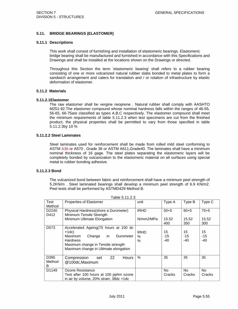
SECTION 7 GENERAL SPECIFICATIONS DIVISION 5 - STRUCTURES
July 2011 Page 5.55
5.11. BRIDGE BEARINGS (ELASTOMER) 5.11.1 Descriptions
This work shall consist of furnishing and installation of elastomeric bearings. Elastomeric bridge bearing shall be manufactured and furnished in accordance with this Specifications and Drawings and shall be installed at the locations shown on the Drawings or directed.
Throughout this Section the term 'elastomeric bearing' shall refers to a rubber bearing
consisting of one or more volcanized natural rubber slabs bonded to metal plates to form a sandwich arrangement and caters for translation and / or rotation of infrastructure by elastic deformation of elastomer.
5.11.2 Materials 5.11.2.1Elastomer
The raw elastomer shall be vergine neoprene . Natural rubber shall comply with AASHTO M251-92.The elastomer compound whose nominal hardness falls within the ranges of 46-55, 56-65, 66-75are classified as types A,B,C respectively. The elastomer compound shall meet the minimum requirements of table 5.11.2.3 when test specimens are cut from the finished product, the physical properties shall be permitted to vary from those specified in table 5.11.2.3by 10 %
5.11.2.2 Steel Laminates
Steel laminates used for reinforcement shall be made from rolled mild steel conforming to ASTM A36 or A570 , Grade 36 or ASTM A611,Grade40. The laminates shall have a minimum nominal thickness of 16 gage. The steel plates separating the elastomeric layers will be completely bonded by vulcanization to the elastomeric material on all surfaces using special metal to rubber bonding adhesive.
5.11.2.3 Bond
The vulcanized bond between fabric and reinforcement shall have a minimum peel strength of 5.2KN/m . Steel laminated bearings shall develop a minimum peel strength of 6.9 KN/m2. Peel tests shall be performed by ASTMD429 Method B.
Table 5.11.2.3
Test Method
Properties of Elastomer unit Type A Type B Type C
D2240 D412
Physical Hardness(shore a Durometer) Minimum Tensile Strength Minimum Ultimate Elongation
IRHD N/mm2/MPa
50+5 15.52 400
60+5 15.52 350
70+5 15.52 300
D573 Accelerated Ageing(70 hours at 100 dc +1dc) Maximum Change in Durometer Hardness Maximum change in Tensile strength Maximum change in Ultimate elongation
IRHD % %
15 -15 -40
15 -15 -40
15 -15 -40
D395 Method B
Compression set 22 Hours @100dc,Maximum
% 35 35 35
D1149 Ozone Resistance Test after 100 hours at 100 pphm ozone in air by volume, 20% strain, 38dc +1dc
No Cracks
No Cracks
No Cracks

SECTION 7 GENERAL SPECIFICATIONS DIVISION 5 - STRUCTURES
July 2011 Page 5.56
5.11.3 Fabrication and Installation 5.11.3.1General Bearing with steel laminates shall be casted as a single unit in a mould and vulcanized under heat and pressure. Casting of elements in separate units and subsequent bonding shall not be permitted, nor shall cutting from larger size cast be permitted. Bearing of similar size to be used in particular bridge shall be produced identical process and in one lot as far as possible. Phased production only resorted to when the total number of bearings is large enough. The moulds used shall be sand blasted, clean of all mill scales and shall be free from all contaminations prior to bonding by vulcanization. Rusted plates with pitting shall not be used. . All edges of plate shall be rounded. Spacers used in moulds to ensure cover and location of laminates shall be of maximum size and number practicable. Care shall be taken to ensure uniform vulcanizing conditions and homogeneity of elastomer through the surfaces and body of bearings. 5.11.3.2 Fabrication tolerances Laminated bearings shall be built to the specified dimensions within the following tolerances and should comply with AASHTO M251-92. ;
1. Overall Height Design thickness 32mm or less -0, +3mm Design thickness over 32 mm -0, +6mm
2. Overall horizontal Dimensions -0, +6mm 3. Thickness of Individual Layers of Elastomer +/-20% of design value,Max+/- 3mm 4. Edge cover -0, +3mm 5. Thickness of Top and Bottom cover layer -0, smaller of 1.5mmand 20% of
nominal cover layer thickness 6. Position of Exposed Connection Members -0, +3mm 7. Parallelism with opposite Face Top and Bottom 1 in 200 Sides 1 in 50 5.11.3.3 Permission for fabrication
At least 30 days before manufacture of the bearings is commenced, the Contractor shall submit, for approval, certificates of tests performed on natural rubber to be used in the bearings. The tests shall be in accordance with AASHTO M251-92.
Manufacture of the bearings shall not commence until the Contractor has received preliminary approval of these details.
5.11.3.4 Testing facilities for fabrication
The manufacturer shall have his plant for all the test facilities required for the process and acceptance control tests. The test facilities and their operation shall be open to inspection by the Engineer on demand.Acceptance testing shall be commenced with the prior submittal of testing programme by the manufacturer to the Engineer and after obtaining his approval. The Contractor shall inform the Engineer at least one month in advance of the date and place of manufacture and test facilities of the bearing. The Contractor shall

SECTION 7 GENERAL SPECIFICATIONS DIVISION 5 - STRUCTURES
July 2011 Page 5.57
make necessary arrangement for the Engineer to inspect the manufacturing process of tests. If the place of manufacture or testing is located overseas, the Contractor shall allow the cost for all expenses incurred by two officers nominated by the Employer for the inspection and testing of bearings. The Contractor shall provide the Engineer with all facilities at the places of manufacture and necessary for such inspection.
5.11.3.5 Quality control certificate
A lot under acceptance shall comprise all bearings, including a pair of extra test bearings of equal or nearly equal size produced under identical conditions of manufacture to be supplied for a particular project. The manufacture shall certify for each lot of bearing under acceptance: - That an adequate system of continuous quality control was operated in his plant - That the entire process remained in control during the production of the lot of bearings
under acceptance as verified from the quality control records /charts which shall be open to inspection of the Engineer on demand.
- A certified copy of results of process control testing done on samples of elastomar used in the production of the lot shall be appended and shall include at least the following information. Composition of the compound-raw elastomer and ash content, the grade of raw elastomer used (including name, source, age on self).Test results of hardness, tensile strength, elongation at break, compression test, accelerated ageing etc. An information card giving the details for the bearings duly certified by the manufacturer shall be appended. The manufacturer of the bearings shall have not less than 5 (five) years successful experience in manufacturing similar type and capacity bearings.
5.11.3.6 Sample Testing of Bearings a) No bearings shall be installed until tests in accordance with AASHTO M251-92
have been completed by an approved laboratory on randomly selected bearings and the bearings, having achieved all requirements, have been approved.
b) Bearings for testing shall be selected by the Engineer and the Engineer shall be present at any testing. The rate of testing of bearings shall be in accordance: Bearing Rate of Testing Type A 1 in 4 c) Each bearing shall be indelibly marked with white paint with an identifying number as directed by the Engineer on the side. This number shall be the bearing identification number for test certificates. Any bearing which fails to pass these requirements shall be indelibly marked 'FAILED' and shall not be used in the works. 'FAILED' bearings will not be paid for. d) Each bearing which passes these tests and complies with this Specification in all other respects shall be indelibly marked 'PASSED'.

SECTION 7 GENERAL SPECIFICATIONS DIVISION 5 - STRUCTURES
July 2011 Page 5.58
e) The Contractor shall submit, for approval, a copy of a test certificate giving test results of the bearings which have passed the tests. f) Notwithstanding anything to the contrary contained in this Specification, the inspection, examination and testing of bearing samples by the Engineer and any consent to proceed with the manufacture of the bearings resulting from such acts shall not prohibit the Engineer from making further inspection, examination, or
tests on the bearings subsequently and rejecting any bearings if shown to be in non-ompliance with this Specification. The Engineer may reject any bearing with flaws or irregularities.
5.11.4 Installation 5.11.4.1 Cement Mortar Bearings pad The cement mortar shall have a minimum compressive strength at 7 days of 30 MPs and shall be composed of one part of cement to 2 parts of sand, unless otherwise approved. All of the sand used in preparation of the mortar shall pass a 4.75 mm sieve. Before placing the cement mortar bearing pads, the Contractor shall prepare a trial mix of his proposed cement mortar mixture. The equipment used to make the trial mix shall be the equipment to be used during the Contract. Three standard 95 mm test cubes shall be cast for compression strength testing and cured for 7 days to the satisfaction of the Engineer. The cubes will be air cured on site in a sheltered location. The three cubes shall be tested for compressive strength at 7 days and each cube shall have a compressive strength of at least 30 MPa. Construction of the bearing pads shall not be started until the strength of the proposed mix has been approved. The provision of all necessary equipment and carrying out of the sampling of the mortar, the casting, on-site curing and testing of specimens shall be done by the Contractor at his cost. 5.11.4.2 Bearings The contractor shall supply, fix in position and maintain the bearings strictly in accordance with the drawings and designs of the contract. Care shall be taken in packing, Transportation, storage and handling to avoid any mechanical damage, contamination with oil, grease and dirt, undue exposure to sunlight and installation of multiple bearings one behind the other on a single line of support shall be of identical dimensions. Bearings shall be placed between true horizontal surfaces (Maximum tolerance 0.2% perpendicular to load) and a true plan position of their centre lines marked on receiving surfaces (maximum tolerances+/-3mm). The level of the top surface of the elastomeric bearing when installed shall not vary from that shown on the Drawings by more than 3 mm. Concrete surfaces shall be free from local irregularities (maximum tolerance+/-1mm in height) If the Cement mortar bearing pads do not meet these tolerances may be repaired by either grinding the surfaces which will be in contact with the bearings to achieve the desired tolerances or by roughening these surfaces and casting a layer of an approved mortar over the complete surface to a minimum of 3 mm and grinding as necessary. If the above tolerances are not achieved, the Engineer may direct that the bearing pad be removed and replaced by a new pad with the specified tolerances.

SECTION 7 GENERAL SPECIFICATIONS DIVISION 5 - STRUCTURES
July 2011 Page 5.59
For cast in place concrete construction of superstructure, where bearings are installed prior to its concreting the forms around the bearings shall be soft enough for easy removal. Any mortar contamination the bearings during concreting shall be completely removed before setting. 5.11.4.3 Maintenance After installation routine maintenance, inspection of all bearings shall be made till the expiry of the maintenance period to check for any surface cracking or signs of damage. Damaged bearings shall be replaced immediately. To avoid difference, all adjacent bearings on the same line of support shall also be checked and removed if necessary. 5.11.5 Measurement Measurement for payment of furnishing and installing elastomeric bearing shall be made of the number of bearings furnished and installed as shown on the Drawings or directed by the Engineer. 5.11.6 Payment The unit rate for elastomeric bearing shall include all costs of materials, labour, tools and plants, fabrication, testing, installation and maintenance as per drawing etc all complete. Pay items shall be
05/11/01(a) - Supply and Installation of Elastomeric bearings - Number 05/11/01(b) - Supply and Installation of Elastomeric bearings - Number 05/11/01(c) - Supply and Installation of Elastomeric bearings - Number 05/11/01(d) - Supply and Installation of Elastomeric bearings - Number Different Size of Elastromeric bearing as below :
a) 300mm x 400mm x 72mm b) 400mm x 500mm x 72mm c) 450mm x 500mm x 72mm d) 500mm x 500mm x 72mm
Size may differ based on designer requirement. Size of different type of bearing will be as per approved drawing.

SECTION 7 GENERAL SPECIFICATIONS DIVISION 5 - STRUCTURES
July 2011 Page 5.60
5.12 BRIDGE BEARINGS (POT BEARING) 5.12.1 Description
The work specified in this Sub-Section includes the supply, manufacture and installation of pot type bearings.
5.12.1.1 Design and Applicable Codes
The bearings shall be designed, manufactured and installed in accordance with this specifications and the applicable requirements of the following standard Codes and Specifications:-
Standard specification for Highway Bridges adopted by AASHTO Part I&II. 5.12.1.2 Manufacturers
The bearing manufacturer proposed as supplier for the bearings shall have not less than 5 years successful experience in manufacturing similar type and capacity bearings and shall be subjected to the approval by the Engineer.
5.12.1.3 Substituted Bearings
The contractor may submit alternative pot bearings based on pot bearings of similar design to that shown for consideration and approval by the Engineer provided they comply with the following:-
(a) Equal or better load carrying and movement capacity; (b) Fabricated by an approved manufacturer; (c) All control dimensions are maintained ; no change in overall height; bearing must fit
within limits of detailed masonry plate; (d) Use unfilled Polytetrafluoroethylene ; (e) Use elastomeric material as a confined medium within the pot; (f) Equal or better than the bearings shown on the drawings in all structural respects.
5.12.2 Materials 5.12.2.1 Metals
(a) Stainless steel : Stainless steel sliding surface shall either be stainless clad steel plate or solid stainless steel meeting the following requirements;-
(i) Stainless steel clad plate shall conform to the requirements of BS 1449: Part 2.
The grade of material for sliding surfaces shall be 316 S16. The backing steel of base metal shall be of Grade 43A to BS 4360. The stainless steel and based metal shall be mill rolled under heat and pressure until they are integrally bonded over their entire interface.
(ii) Solid stainless steel plate shall conform to the requirements of Bs 1449: Part1.
(b) Structural Steel:
Structural steel components of the bearing shall comply with requirements of B5 4360. For pot bearings, the bases pot shall be machined from a solid steel plate.

SECTION 7 GENERAL SPECIFICATIONS DIVISION 5 - STRUCTURES
July 2011 Page 5.61
All ferrous metal (other than stainless steel) shall be fabricated from the grade steel specified above with the additional requirements that the steel shall contain 0.35 to 0.5% copper to enhance its weathering characteristics. (i) Anchor bolts, Hex Nuts And Washers
Anchor Bolts, Hex Nuts and Washers shall be fabricated from the steel Grade 43 and complying with the requirements of BS 4360 and be sized and threaded in conformance to the requirements of BS 3692 for Anchor Bolts and Hex Nuts and BS 4320 for washers.
(ii) Anchor Bolts, Nuts And Washers
Anchor Bolts, Nuts and Washers shall be galvanized and complying with the requirements of BS 729.
(iii) Countersunk Screws
Countersunk Screws shall be carbon steel (equivalent to alloy 43, BS 4360) cylindrical head cap screws, meeting the applicable requirements of BS 4933.
(iv) End Welded Shear Studs End Welded shear studs shall be fabricated to the requirements of BS 4360.
5.12.2.2 Poly tetra fluoro ethylene (PTFE)
PTFE resin shall be 100 per cent virgin material meeting the requirements of BS 3784: Grade A . The composition of filled PTFE shall be such that its coefficient of friction is not more than twice the coefficient of friction of pure PTFE when measured under the same conditions.
(a) Filler material
Filler material, when used, shall be milled glass fibers, carbon or other approved inert filler materials.
(b) Adhesives
Adhesives for bonding PTFE to Backing Plates shall produce a bond with minimum peel strength of 4N/mm width when tested in accordance with BS 5350: Part C9. They shall be resistant to the action of lubricants, atmospheric and biological agents and temperature to which bearing may be subject;
(c) Lubricant
The lubricant used shall retain its properties within the temperature range of -270 to + 47 0C. It shall not change its consistency or affect the constituent parts of the bridge bearings. The lubricant shall have the following properties:-
(i) Worked penetration range of 240 to 280 determined in accordance with BS 5296
(ii) a solidification point < A40 0C (iii) a bleeding < 4% when tested in accordance with BS 5297 using 150 0C for
24 hour. 5.12.2.3 Elastomer

SECTION 7 GENERAL SPECIFICATIONS DIVISION 5 - STRUCTURES
July 2011 Page 5.62
(a) Elastomer material shall be good quality natural rubber complying with the requirements of MS 3.51 SMR 5 Grade or better shall be used. All ingredients shall be uniformly dispersed.
(b) the physical properties of the vulcanized rubber when tested according to BS 903 shall
conform to the requirements the following physical properties of rubber.
(c) physical properties of Rubber
The physical properties of the vulcanized rubber when tested according to appropriate standard shall conform to the requirements of Table 2.11 Bearings whose nominal hardness falls within the ranges of 46-55, and 66-75 are classified as types A, B and C respectively and the properties of the vulcanizates shall conform to the requirements of the respective types. However in all cases the hardness of a single size and design of bearings shall be within a maximum range of ±5 IRHD. For the purpose of verifying that the bearings conform to the requirements of this clause, all test specimens of ozone resistance shall be taken from an outside surface of a bearing and all other test specimens shall be taken from and outside and middle third of a bearing.
Table 2.12.2 Physical Properties of Elastomer
Type A Type B Type C Methods of Tests1 Nominal Hardness
(IRHD)
46 to 55 56to 65 66 to 75 ISO 48
2 Tensile strength (N/sq.mm)min
21 17 14 ISO37
3 Elongation at Break (%), min
550 450 300 ISO37
4 Compression set after 24 hours at 70`c and 25 Compression (%) Max.
30 30 30 ISO 815
5 Ozone resistance test after 96 hours at 25 pphm ozone, 40 0C 20% strain
No visible cracks
No visible cracks
No visible cracks
ISO 1431 Part 1
6 Accelerated ageing for 168 hours at 70 0C
6.1) Change in tensile
strength (%)
6.2) Change in
elongation at break,(%)
±15 A20
±15 A20
±15 A20
ISO188(air oven) ISO37 ISO48
5.12.2.4 Coal Tar Epoxy
Coal Tar Epoxy shall comply with the requirements of BS5493 Ref Kf 3B. 5.12.2.5 Preformed Fabric Pads

SECTION 7 GENERAL SPECIFICATIONS DIVISION 5 - STRUCTURES
July 2011 Page 5.63
Preformed Fabric Pads shall be compressed of multiple layers of 227 gram cotton duck impregnated and bound with high quality natural rubber or of equivalent and equally suitable materials compressed into resilient pads of uniform thickness the number of splices shall be subs as to produce the specified thickness after compression and vulcanizing. The finished pads shall withstand compression loads perpendicular to the plane of the laminations of not less than 69KN sq.mm without detrimental reduction in thickness of extrusion.
5.12.2.6 Sealing Rings
Sealing rings for containing the confined medium in pot bearings shall meet the following requirements:- (a) Non-corrosive Materials; (b) Withstands or transmit all impose loads; (c) Allow free movement of the piston; (d) Contains the confined medium within the pot under the maximum static dynamic
loading; (e) Prevents contamination of the confined medium with foreign matter. (f) Designed to be flushed with the outside surface of the Elastomer to ensure proper
sealing. 5.12.2.7 Grouts
Non shrink grouts for setting anchor bolts shall be of an approved quality and tested in accordance with the requirements of BS 1881,BS 4550, BS4551 and BS 5075: Part 2.
5.12.3 Design Requirements
Design parameters shall comply with the following requirements:- 5.12.3.1 Elastomeric Disc
The maximum design compressive stress shall be 40 N/sq.mm. 5.12.3.2 Sliding Surfaces
Sliding surface shall accommodate translation by sliding of a hard mating surface of stainless steel across a PTFE surface.
(a) Stainless steel Stainless steel sliding surface shall be accurate, flat surface with Brinnell hardness of 125 minimum it shall comply with the following requirements (i) Stainless steel sliding surface shall completely cover the PTFE surface in
all operating positions of the bearing. (ii) Stainless steel sliding surface shall be positioned so that the sliding
movement causes the dirt and dust accumulation to fall from the surface of the stainless steel without contaminating the PTFE.
(b) PTFE Sliding Surface
Holes in PTFE sliding surface shall not be permitted.
(c) Coefficient of Friction Unless otherwise specified the minimum coefficient of friction used in the design shall be as Table 5.12.
Table 5.12-1 Coefficient of Friction for Sliding

SECTION 7 GENERAL SPECIFICATIONS DIVISION 5 - STRUCTURES
July 2011 Page 5.64
Bearing stress (N/sq.mm)
Coefficient of Friction
5 10 20 30 and over
0.08 0.06 0.04 0.03
5.12.3.3 Rotation The rotation of pot bearings about a horizontal axis shall not exceed 0.15. 5.12.3.4 Movement
The pot bearings shall accommodate the expansion and contraction movements, as shown on the Drawings.
5.12 .3.5 Welding
Welding to steel plate has a bonded PTFE surface may be permitted provided welding procedures are established which restrict the maximum temperature reached by the bond area to less than 1500 (as determined by temperature indication wax pencils or other suitable means approved by the Engineer)
5.12.3.6 Submission of shop drawings
The Contractor shall, before the fabrication of any bearings, submit shop drawings to the Engineer for approval the shop drawings shall include (a) Plan and elevation of the bearing ; (b) Complete details and sections showing all materials incorporated with the
bearing ; (c) All B5, ASTM or other material designations; (d) Vertical and horizontal load capacity; (e) Rotation and translation capacity; (f) Compression stress on all sliding surfaces, as well as on the surfaces of the
confines medium, at maximum and minimum design loads; (g) Complete design calculations to demonstrate compliance with the
specification; (h) Details of corrosion properties to metal components; (i) Details of fixing to both the superstructure and the substructure; (j) Method of installation; (k) All other information requires by the Engineer to facilitate his consideration the
contractor’s proposal. The Contractor’s submission shall be made at least one month prior to the date by which approval of his proposals is required. The contractor shall be responsible for ensuring that sufficient time is allowed for the submission and approval of his proposals; and for the testing and delivery of the bearings, to avoid delaying the works.
5.12.4 Certifications
The Contractor shall furnish Certified Test Reports, Material Certificates and a Certificates of Compliance for each bearing in accordance with the Engineer’s instructions.
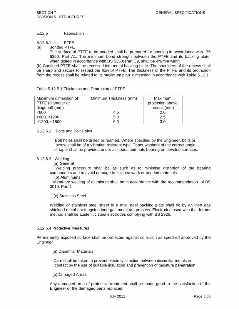
SECTION 7 GENERAL SPECIFICATIONS DIVISION 5 - STRUCTURES
July 2011 Page 5.65
5.12.5 Fabrication 5.12.5.1 PTFE (a) Bonded PTFE
The surface of PTFE to be bonded shall be prepared for bonding in accordance with B5 5350: Part A1. The minimum bond strength between the PTFE and its backing plate, when tested in accordance with BS 5350: Part C9, shall be 4N/mm width
(b) Confined PTFE shall be recessed into metal backing plate. The shoulders of the recess shall be sharp and secure to restrict the flow of PTFE. The thickness of the PTFE and its protrusion from the recess shall be related to its maximum plan dimension in accordance with Table 5.12.1 Table 5.12.5.1:Thickness and Protrusion of PTPE Maximum dimension of PTFE (diameter or diagonal) (mm)
Minimum Thickness (mm) Maximum projection above
recess (mm) <600 >600, <1200 >1200, <1500
4.5 5.0 6.0
2.0 2.5 3.0
5.12.5.2. Bolts and Bolt Holes Bolt holes shall be drilled or reamed. Where specified by the Engineer, bolts or screw shall be of a vibration resistant type. Taper washers of the correct angle
of taper shall be provided under all heads and nuts bearing on beveled surfaces.
5.12.5.3 Welding (a) General
Welding procedure shall be as such as to minimise distortion of the bearing components and to avoid damage to finished work or bonded materials
(b) Aluminums Metal-arc welding of aluminum shall be in accordance with the recommendation of BS 3019: Part 1
(c) Stainless Steel
Welding of stainless steel sheet to a mild steel backing plate shall be by an inert gas shielded metal-arc tungsten inert gas metal-arc process. Electrodes used with that former method shall be austenitic steel electrodes complying with BS 2926.
5.12.5.4 Protective Measures Permanently exposed surface shall be protected against corrosion as specified approved by the Engineer. (a) Dissimilar Materials Care shall be taken to prevent electrolytic action between dissimilar metals in contact by the use of suitable insulation and prevention of moisture penetration (b)Damaged Areas
Any damaged area of protective treatment shall be made good to the satisfaction of the Engineer or the damaged parts replaced.

SECTION 7 GENERAL SPECIFICATIONS DIVISION 5 - STRUCTURES
July 2011 Page 5.66
5.12.6 Testing 5.12.6.1Testing facilities for fabrication
The manufacturer shall have his plant for all the test facilities required for the process and acceptance control tests. The test facilities and their operation shall be open to inspection by the Engineer on demand. Acceptance testing shall be commenced with the prior submittal of testing programme by the manufacturer to the Engineer and after obtaining his approval.The Contractor shall inform the Engineer at least one month in advance of the date and place of manufacture and test facilities of the bearing. The Contractor shall make necessary arrangement for the Engineer to inspect the manufacturing process of tests. If the place of manufacture or testing is located overseas, the Contractor shall allow the cost for all expenses incurred by two officers nominated by the Employer for the inspection and testing of bearings. The Contractor shall provide the Engineer with all facilities at the places of manufacture and necessary for such inspection.
5.12.6.2 Sample testing: Procedures and Compliance
(a) Load Testing Both vertical and horizontal loads shall be applied to the bearing in the most adverse combinations as specified on the Drawing or in the Schedule of Bearings. Load transfer due to tilting of bearing shall be taken into account. Before recorded measurements, the bearing shall be embedded in by applying a load equal to the serviceability limit state and then releasing it. The test loads shall then be applied in increments and load deflection measurements shall be recorded for each increment. The rate of loading shall be slow enough to avoid any adverse shock effects and the maximum load shall be maintained until any obvious short-term creep has ceased.
The load shall then be removed in decrements and load deflection measurements made each decrement. After complete unloading, the amount of set shall be checked and if significant, the loading and unloading cycle shall be repeated. If the set is shown to be progressive, then the bearing is deemed not to comply with this Specification. For compliance, tested bearing shall show no sign of visible damage or permanent deformation of any part due to loading cycles subsequent to the initial bedding in cycle.
(b) Friction
Friction testing of sliding surfaces shall be carried out as follows:-
(i) A vertical load equal to the permanent load specified on the drawing or listed the schedule of Bearings shall be applied to a pair of sliding surface mounted back to back between the plates of a compression testing rig. A horizontal force shall be applied to the pair of sliding plates sufficient to cause movement of not less than 25mm between the stainless steel and PTFE sliding surface. The maximum force required to cause this movement shall be recorded. The load shall then be removed from the rig and inspected.
(ii) The coefficient of friction shall be calculated as (maximum horizontal force) /22x
vertical load for each test position and shall in no case exceed Table2.11-2
(iii) After testing the stainless steel shall be checked for flatness, which must be within the specified limits. The bond to the backing plate shall be unaffected. The PTFE shall be free from mechanical damage

SECTION 7 GENERAL SPECIFICATIONS DIVISION 5 - STRUCTURES
July 2011 Page 5.67
(iv) The tests shall be carried out at room temperature. The PTFE surface shall be lubricated with the lubricant to be used in service. Fro compliance, tested bearing shall show no apparent surface flaws.
5.12.7 Products Delivery Storage and Handling 5.12.7.1Assembly and Marking
Each pot bearing shall be assembled at the plant, marked for identification and delivered to the construction site as a complete unit. Each bearing shall be marked to indicate the normal position of the bearing
5.12.7.2 Care and Protection
During handling, transport, storage and installation, bearings shall be kept clean and protected from mechanical damage, heat, contaminates and other deleterious effects.
5.12.8 Installation 5.12.8.1 General
Bearings which have been pre-assembled shall not be dismantled except with the prior approval of the Engineer if for any reason the bearing has been dismantled, it shall be done under expert supervision and the manufacturer’s assistance shall be sought. All bearings whether require providing horizontal restraint or not, shall be fixed to the superstructure with the mechanical fixings or similar. Reliance on the friction between the bearing and the superstructure or substructure to resist part of the horizontal may be permitted provided faces of safety of not less than 1 1½ is applied to the proven coefficient of friction. The worst combination of vertical load and horizontal load shall be considered.
The Contractor shall carefully check the level of any surface, plinth or bed upon which a bearing will rest and he shall make due allowance for any difference in the depth the bearing to be installed from that assumed on the Drawing. If necessary he shall adjust the levels of the substructure to ensure that the level of the superstructure will be at the required level on completion. Unless specified all bearings shall be installed with bottom plate horizontal. For case where tapered top plate is required to take up the longitudinal elevation, welding of bolting to the top of the bearing is not allowed. The tapered top plate must be machined on the bearing itself. Any temporary lock devices for bearings shall be removed before a post-tensioned case in-place superstructure is stressed. For other type of superstructures, the Engineer shall agree the time for removal of any locking devices shall be agreed by the Engineer. Care shall be taken to avoid displacing bearings during formwork erection, steel fixing and concreting.
5.12.8.2 Tolerances
(a) Bearings shall be located so that their centerlines are within ±3mm of their
correct position. The level of bearings shall be within tolerance of ±0.0001 times the adjacent span or lesser of the adjacent spans, but shall not exceed ±5mm. Bearings shall be set to their correct inclination within a tolerance of 1 in 200mm in any direction.
(b) Departure from the plane between twin or multiple bearings shall be within tolerance specified on the drawing.
(c) Bearing shall be installed so that the directions of their horizontal axis are within tolerance of ±0.005 radian from their correct alignment.

SECTION 7 GENERAL SPECIFICATIONS DIVISION 5 - STRUCTURES
July 2011 Page 5.68
5.12.9 Shock Transmission Units 5.12.9.1 General
Steel components of shock transmission unit with transverse restraint bearings shall comply with the general requirements except as otherwise stated herein. Other components shall comply with Clauses 2.11. Protection of steelwork against corrosion shall be as specified in SIS 0559000,BS 729, BS 6044, BS 2992, BS 3900, BS 2569 Part-1, BS 4921, ISO 8503/Part-2, SSPC Paint, SSPC SP-2, SSPC SP-3 Seismic shock transmission devices shall comply with Clause 3.4. Details of shock transmission unit shall be as shown on the working Drawings. The design of the restraints shall make provision facilitate inspection of the device if construction incorporates the robust steel pintle restraint shown on the Consultant’s reference Designs then replacement is not anticipated during the designs life of the structure. If, in the opinion of the Engineer, an accepted alternative device may require replacement during the design life of the bridge, then design shall facilitate replacement.
5.12.9.2 Model Testing of Yielding shock Transmission Unit
Scale model rests shall be carried out on shock transmission unit designed to yield under seismic loading. The Contractor shall submit to the Engineer for approval full details of his proposals for such testing including where the tests are to be carried out and curricula vitae for the key personnel involved. The Engineer shall be given access to inspect testing at all times and shall have the authority to instruct further amended tests at his discretion. Factual reports including all results shall be submitted to the Engineer within one week of the completion of each test. An interpretative report shall be submitted to the Engineer for his approval within one week of the completion of testing. The models shall not be smaller than one fifth of the size of the actual restraint. A minimum of six clearly identified test specimens shall be prepared. A minimum of three specimens shall be subjected to the nominal test sequence, a minimum of two specimens shall be subjected to an arbitrary 30% excess deformation and one further specimen tested to a deformation history chosen in the light of the other test results. Allowance shall be made for a minimum of six further specimens and having different details to assist in design optimization. The models shall accurately represent the transmission and its fixing arrangements. Materials tests shall be carried out to relate the material strength and ductility to the materials in the actual transmission.
The nominal test sequence shall accurately represent the deformation history expected for actual transmission. This shall cover both magnitude and rate of deformation The maximum force developed in each direction of deformation shall be recorded for every cycle, and the force deformation relationship recorded for the first three cycles and thereafter every fifth cycle. The physical appearance of the specimen after the test shall be carefully recorded.
5.12.10 Measurement
The method of measurement for payment shall be in number for each Bearing and for each shock Transmission Unit with Transverse Restraints.

SECTION 7 GENERAL SPECIFICATIONS DIVISION 5 - STRUCTURES
July 2011 Page 5.69
5.12.11 Payment
The Contract unit rate for the items shown in the BOQ shall include cost of all materials, equipment and other incidental charges for supply, installation and fixing in all respects per these specifications and as shown in the drawing. Pay items shall be 05/12/01(a) Supply and Installation of Pot bearings Number 05/12/01(b) Supply and Installation of Pot bearings Number 05/12/01(c) Supply and Installation of Pot bearings Number 05/12/02 Supply and Installation of Shock Transmission units Number Different size of bearing as below :
a) 500mm X 500mm X 72mm b) 500mm X 450mm X 72mm c) 400mm X 300mm X 72mm
Size may differ based on designer requirement. Size of different type of bearing will be as per approved drawing.

SECTION-7 GENERAL SPECIFICATIONS DIVISION 5- STRUCTURES
DIVISION 6 INCIDENTALS

SECTION 7 GENERAL SPECIFICATIONS DIVISION 6 - INCIDENTALS
July 2011 Page 6.41
DIVISION 6 - INCIDENTALS Page
6.1 SLOPE AND STREAMBED PROTECTION ....................................................................... 1 6.1.1 Description .................................................................................................................. 1 6.1.2 Materials ...................................................................................................................... 1
6.1.2.1 Riprap Protection to Slopes .................................................................................... 1 6.1.2.2 Protection to River Bank ......................................................................................... 1 6.1.2.3 Mortar ..................................................................................................................... 1 6.1.2.4 Concrete Slope Protection ...................................................................................... 1
6.1.3 Construction Methods ................................................................................................ 1 6.1.3.1 General ................................................................................................................... 2 6.1.3.2 Preparation ............................................................................................................. 2 6.1.3.3 Cut-off Walls ........................................................................................................... 2 6.1.3.4 Laying ..................................................................................................................... 3
6.1.4 Measurement ............................................................................................................... 3 6.1.5 Payment ....................................................................................................................... 3
6.2 REINFORCED CONCRETE CULVERT PIPES .................................................................. 5
6.2.1 Description .................................................................................................................. 5 6.2.2 Materials ...................................................................................................................... 5
6.2.2.1 Reinforced Concrete Pipe ....................................................................................... 5 6.2.2.2 Mortar ..................................................................................................................... 5 6.2.2.3 Reinforcement ........................................................................................................ 5 6.2.2.4 Bricks ...................................................................................................................... 5
6.2.3 Construction Methods ................................................................................................ 5 6.2.3.1 General ................................................................................................................... 5 6.2.3.2 Excavation .............................................................................................................. 5 6.2.3.3 Bedding .................................................................................................................. 6 6.2.3.4 Installation .............................................................................................................. 6 6.2.3.5 Backfilling ............................................................................................................... 6
6.2.4 Measurement ............................................................................................................... 7 6.2.5 Payment ....................................................................................................................... 7
6.3 DRAINAGE AND OTHER MISCELLANEOUS STRUCTURES ......................................... 8
6.3.1 Description .................................................................................................................. 8 6.3.2 Materials ...................................................................................................................... 8 6.3.3 Construction Methods ................................................................................................ 8
6.3.3.1 General ................................................................................................................... 8 6.3.3.2 Manholes and Catch Basins ................................................................................... 8 6.3.3.3 Concrete Side Ditch and U-Drain ........................................................................... 8 6.3.3.4 Headwalls to Culvert Pipes ..................................................................................... 8
6.3.4 Measurement ............................................................................................................... 8 6.3.5 Payment ....................................................................................................................... 9
6.4 KERB, GUTTER AND EDGE DETAIL ............................................................................. 10
6.4.1 Description ................................................................................................................ 10 6.4.2 Materials .................................................................................................................... 10 6.4.3 Construction Methods .............................................................................................. 10
6.4.3.1 Concrete Kerb and Gutters ................................................................................... 10 6.4.3.2 Edge Detail ........................................................................................................... 10
6.4.4 Measurement ............................................................................................................. 10 6.4.5 Payment ..................................................................................................................... 11
6.5 ROAD MARKINGS .......................................................................................................... 12
6.5.1 Description ................................................................................................................ 12 6.5.2 Materials ……………………………………………………………………………………12
6.5.2.1 Hot Applied Thermoplastic Materials .................................................................... 12 6.5.2.2 Road Marking Paint .............................................................................................. 12

SECTION 7 GENERAL SPECIFICATIONS DIVISION 6 - INCIDENTALS
July 2011 Page 6.42
6.5.2.3 Reflecting Road Studs .......................................................................................... 13 6.5.3 Construction Methods .............................................................................................. 13
6.5.3.1 Thermoplastic Materials ....................................................................................... 13 6.5.3.2 Road Marking Paint .............................................................................................. 14 6.5.3.3 Reflecting Road Studs .......................................................................................... 15 6.5.3.4 Tolerances ............................................................................................................ 16 6.5.3.5 Defective Materials of Workmanship .................................................................... 16 6.5.3.6 Protection of Traffic .............................................................................................. 16
6.5.4 Measurement ............................................................................................................. 16 6.5.5 Payment ..................................................................................................................... 16
6.6 TOPSOIL .......................................................................................................................... 18
6.6.1 Description ................................................................................................................ 18 6.6.2 Materials .................................................................................................................... 18 6.6.3 Construction Methods .............................................................................................. 18 6.6.4 Measurement ............................................................................................................. 18 6.6.5 Payment ..................................................................................................................... 18
6.7 GRASSING ....................................................................................................................... 19
6.7.1 Description ................................................................................................................ 19 6.7.2 Materials .................................................................................................................... 19 6.7.3 Construction Methods .............................................................................................. 19 6.7.4 Measurement ............................................................................................................. 19 6.7.5 Payment ..................................................................................................................... 19
6.8 GUARDRAIL ..................................................................................................................... 21
6.8.1 Description ................................................................................................................ 21 6.8.2 Materials .................................................................................................................... 21
6.8.2.1 General ................................................................................................................. 21 6.8.2.2 Concrete and Reinforcement Steel ....................................................................... 21 6.8.2.3 Steel Posts and rails ............................................................................................. 21 6.8.2.4 Bolts and Nuts ...................................................................................................... 21
6.8.3 Construction Methods .............................................................................................. 21 6.8.3.1 Posts .................................................................................................................... 21 6.8.3.2 Rails ..................................................................................................................... 21
6.8.4 Measurement ............................................................................................................. 21 6.8.5 Payment ..................................................................................................................... 21
6.9 CONCRETE MONUMENTS AND POSTS ........................................................................ 22
6.9.1 Description ................................................................................................................ 22 6.9.2 Materials .................................................................................................................... 22 6.9.3 Construction Methods .............................................................................................. 22 6.9.4 Measurement ............................................................................................................. 22 6.9.5 Payment ..................................................................................................................... 22
6.10 TRAFFIC SIGNS ....................................................................................................... 23
6.10.1 Description ................................................................................................................ 23 6.10.1.1 General ................................................................................................................. 23 6.10.1.2 Sizes, Colours and Types ..................................................................................... 23 6.10.1.3 Alternative Designs and Materials ........................................................................ 23
6.10.2 Materials .................................................................................................................... 23
6.10.2.1 Mounting Posts ..................................................................................................... 23 6.10.2.2 Sign Plates ........................................................................................................... 23 6.10.2.3 Frames and Stiffening .......................................................................................... 24 6.10.2.4 Fixtures and Fittings ............................................................................................. 24 6.10.2.5 Preservatives, Paints and Finishes ....................................................................... 24
6.10.3 Construction Methods .............................................................................................. 26 6.10.3.1 General ................................................................................................................. 26

SECTION 7 GENERAL SPECIFICATIONS DIVISION 6 - INCIDENTALS
July 2011 Page 6.43
6.10.3.2 Mounting Posts ..................................................................................................... 26 6.10.3.3 Sign Plates ........................................................................................................... 26 6.10.3.4 Frames and Stiffening .......................................................................................... 26 6.10.3.5 Fixtures and Fittings ............................................................................................. 27 6.10.3.6 Preparation and Painting ...................................................................................... 27 6.10.3.7 Finish of Sign Faces ............................................................................................. 28 6.10.3.8 Concrete Embedment of Posts ............................................................................. 28
6.10.4 Measurement ............................................................................................................. 28 6.10.5 Payment ..................................................................................................................... 29
6.11 RUMBLE STRIP 6.11.1Description .......................................................................................................... 30 6.11.1.1General ............................................................................................................ 30 6.11.1.2 6.11.1.3 Alternative Designs and Materials .................................................................. 30
6.11.2 Materials
6.11.2.1 Tack Coat .................................................................................................................. 31 6.11.2.2 Bituminous Mixture.................................................................................................... 31 6.11.2.3 Thermoplastic Paint .................................................................................................. 31 6.11.2.4 Form Work ................................................................................................................ 31
6.11.3 Construction Methods
6.11.3.1 Surface Preparation ................................................................................................. 31 6.11.3.2 Application of Tack Coat .......................................................................................... 31 6.11.3.3 Placing of Bituminous Mixture .................................................................................. 32 6.11.3.4 Compaction of Bituminous Mixture .......................................................................... 32
6.11.4 Measurement 6.11.5 Payment
6.12 PROTECTION OF WORKS .............................................................................................. 33
6.12.1 Scope of Work ........................................................................................................... 33 6.12.2 Bricks For Mattressing ............................................................................................. 33
6.12.2.1 General ................................................................................................................. 33 6.12.2.2 Sampling ............................................................................................................... 33 6.12.2.3 Dimension ............................................................................................................. 33 6.12.2.4 Appearance .......................................................................................................... 33 6.12.2.5 Unit Weight ........................................................................................................... 33 6.12.2.6 Crushing Strength ................................................................................................. 33 6.12.2.7 Water Absorption .................................................................................................. 33
6.12.3 Geotextile Filter Fabric ............................................................................................. 33 6.12.4 Mattressing................................................................................................................ 34
6.12.4.1 General ................................................................................................................. 34 6.12.4.2 Bricks .................................................................................................................... 34 6.12.4.3 Galvanized Wire Mesh.......................................................................................... 34 6.12.4.4 Placement ............................................................................................................. 34
6.12.5 Measurement ............................................................................................................. 35 6.13 SLOPE PROTECTION WORKS BY PALISIDING ........................................................... 36
6.13.1 Description .................................................................................................................. 36 6.13.2 Requirement of Wooden Piles .................................................................................... 36 6.13.3 Construction Methods ................................................................................................. 36 6.13.4 Measurement .............................................................................................................. 36 6.13.5 Payment ..................................................................................................................... 36
SECTION 7 GENERAL SPECIFICATIONS DIVISION 6 - INCIDENTALS
July 2011 Page 6.44
6.14 MOBILIZATION FOR DECK SLAB REPAIRING WORK, ETC ---------------------------------------- 37 6.14.1 Description --------------------------------------------------------------------------------------------------- 37 6.14.2 Materials -------------------------------------------------------------------------------------------------- 37 6.14.4 Measurement------------------------------------------------------------------------------------------------ 37 6.14.5 Payment --------------------------------------------------------------------------------------------------- 37
6.15 CONCRETE GUIDE POST 6.15.1 Description --------------------------------------------------------------------------------------------------- 38 6.15.2 Materials ------------------------------------------------------------------------------------------------------ 38 6.15.3 Construction Methods ------------------------------------------------------------------------------------- 38 6.15.3.1 Guide Post --------------------------------------------------------------------------------------------------- 38 6.15.4 Tolerances---------------------------------------------------------------------------------------------------- 38 6.15.5 Measurement------------------------------------------------------------------------------------------------ 38 6.15.6 Payment ------------------------------------------------------------------------------------------------------ 38
6.16 CONCRETE KILOMETRE POSTS -------------------------------------------------------------------------- 39 6.16.1 Description --------------------------------------------------------------------------------------------------- 39 6.16.2 Materials ------------------------------------------------------------------------------------------------------ 39 6.16.3 Construction Methods ------------------------------------------------------------------------------------- 39 6.16.4 Measurement ----------------------------------------------------------------------------------------------- 39 6.16.5 Payment ------------------------------------------------------------------------------------------------------ 39
6.17 RCC PALISIDING ------------------------------------------------------------------------------------------- 40 6.17.1 Description ---------------------------------------------------------------------------------------------------- 40 6.17.2 Materials ------------------------------------------------------------------------------------------------------- 40 6.17.3 Construction Methods -------------------------------------------------------------------------------------- 40 6.17.3.1 RCC Post ------------------------------------------------------------------------------------------------------ 40 6.17.3.2 Precast Planks ----------------------------------------------------------------------------------------------- 40 6.17.4 Tolerances ---------------------------------------------------------------------------------------------------- 40 6.17.5 Measurement ------------------------------------------------------------------------------------------------ 40 6.17.6 Payment ------------------------------------------------------------------------------------------------------- 40

SECTION 7 GENERAL SPECIFICATIONS DIVISION 6 - INCIDENTALS
July 2011 Page 6.1
6.1 SLOPE AND STREAMBED PROTECTION
6.1.1 Description
This work shall consist of the provision and installation of protection for stream banks, riverbanks, embankment slopes, cut slopes and other surfaces composed of erodible materials where protection is desired. Generally, protection to slopes will form an impervious layer constructed in or on designated surfaces and shall have at its bottom and ends anti-scour devices, such as cut-off walls or toe walls. Protection to the riverbanks shall form a graded aggregate scour protection. The protection shall be constructed to the shapes and dimensions shown on the Drawings or as required by the Engineer.
6.1.2 Materials
6.1.2.1 Riprap Protection to Slopes
Stone for riprap shall consist of stone boulders of suitable size and shape. The stone shall be dense, resistant to the action of air and water, and suitable in all other respects for the purpose intended. Alternatively concrete blocks manufactured from stone chips maybe used, if shown on the Drawings. The minimum thickness of stone shall be 100 mm (measured perpendicular to face of riprap). No face dimension shall be less than the thickness of the stone. Unless otherwise specified, the stones shall weigh not less than 10 kilograms each. The minimum thickness of the concrete block shall be 600 mm with a weight not less than 20 kg, with the concrete being Class 20 manufactured in accordance with Section 5.1 of the Specification.
6.1.2.2 Protection to River Bank
The following materials shall be used: • Coarse gravel with sizes ranging from 5 - 40 mm and of approved grading. • Cobblestones with sizes ranging from 50 - 100 mm and of approved grading. • Boulders with sizes ranging from 100 - 200 mm. The soundness of gravel and stones shall be approved by the Engineer. The boulders shall be dense, resistant to the action of air and water and suitable in all other respects for the purpose intended.
6.1.2.3 Mortar
Mortar shall be composed of one part of cement and two parts of sand by dry loose volume and sufficient water to make a mortar that can be easily handled and trowelled. Retempering of mortar that has not been used for periods of 45 minutes or longer will not be permitted. Cement for mortar shall conform to the requirement of Section 5.1 of these Specifications.
6.1.2.4 Concrete Slope Protection
Concrete and reinforcement used in the construction of concrete facing for slopes shall be in accordance with Sections 5.1 and 5.2 of these Specifications, respectively, except where modified by the Drawings.
6.1.3 Construction Methods

SECTION 7 GENERAL SPECIFICATIONS DIVISION 6 - INCIDENTALS
July 2011 Page 6.2
6.1.3.1 General
A) Grouted Riprap Unless otherwise specified riprap pavement shall always be constructed as an impervious layer upon designated surfaces. Unless otherwise specified riprap pavement shall have mortared joints and 40 mm weepholes per 2 m measured in both directions. B) Loose Stone Riprap Stone protection shall be carried out as shown on the Drawings. The stone protection shall consist of the following layers: Stone Type Grading (mm) Layer Thickness (mm)Boulders 100 - 200 300Cobble Stones 50 - 100 200Coarse Gravel 5 - 40 150 Total 650
C) Concrete Slope Protection Concrete slope protection shall be carried out as shown on the Drawings. Concrete shall be Class 20 and the reinforcement shall conform to the requirements of Section 5.2. The construction methods shall also conform to the requirements of Sections 5.1 and 5.2.
6.1.3.2 Preparation
A) Grouted Riprap (stone or concrete blocks) and Concrete Slope Protection Excavation or construction of embankments shall be processed to planned shapes and dimensions, as if there were no protection, to allow some excavation immediately prior to the placing of the protection. The Contractor is responsible for discussing with the Engineer, his proposed method or constructing embankments in areas to be protected so that the proper procedure can be agreed. The areas to be covered shall, at the proper time, be laid out to intended positions, and all necessary cut and fill stakes, batter boards, and construction lines set up. Every effort shall be made to have the surfaces in such condition as to require some excavation immediately prior to the laying of the protection. Where, however, low areas are encountered they shall be backfilled and thoroughly tamped at the earliest practical time in advance of the laying of masonry, to avoid settlement after placing riprap. It is not necessary that the entire area to be protected will be excavated and fine graded in advance of the laying. Work should always be laid upon a freshly excavated and stable surface. B) Loose Stone Riprap Stone protection work shall where possible be carried out during periods when low river levels allow construction in the dry. Approval of the Engineer shall be obtained prior to placing stone protection under water. The area of the stone protection shall be prepared by excavating or dredging to the levels shown on the Drawings or as directed by the Engineer. It is not necessary that the entire area to be protected will be excavated in advance of the laying. Gravel should always be laid upon a freshly excavated surface.
6.1.3.3 Cut-off Walls

SECTION 7 GENERAL SPECIFICATIONS DIVISION 6 - INCIDENTALS
July 2011 Page 6.3
Riprap and concrete slope protection shall always be accompanied by a bottom cut-off wall, unless otherwise instructed by the Engineer. The cut-off wall shall be constructed of reinforced concrete to the dimensions and details shown on the Drawings. Concrete shall be in accordance with Section 5.1 and reinforcement in accordance with Section 5.2.
6.1.3.4 Laying
A) Riprap Protection and Concrete Slope Protection After cut-off concrete has been placed and accepted, the laying of slope protection shall be commenced in tight contact with the cut-off concrete and laid from the bottom towards the top. In the case of riprap protection the stones, boulders or concrete blocks shall be bedded on 50 - 100 mm of free draining sand or gravel as directed and shall be laid in close contact. The interstices may be partly filled with spalls or small stones. For the concrete slope protection, the reinforcing steels shall be laid and the concrete poured according to the requirements described in Sections 5.1 and 5.2. Weep holes to riprap pavement shall be covered on the inside with stones and gravel filters extending 300 mm from the hole in all directions and connecting with the porous bedding material. All joints and openings to riprap pavement shall be filled solidly with mortar. Weep holes for the concrete slope protection and the joints shall be prepared and constructed as shown on the Drawings. B) Loose Stone Riprap All materials shall be transported and laid by methods, which do not cause damage to material previously laid. Boulders shall be placed well packed and wedged together without mortar.
6.1.4 Measurement
Riprap and concrete slope protection shall be measured for payment on the basis of the area in square metres. Linear dimensions will be taken in not less than two directions, and of sufficient number so that averages can be obtained, and the product of the averages shall be the area considered for payment. Where slopes exist, measurement will be along the surface of the slopes. Loose Stone Riprap shall be measured in cubic metres of stone protection as the total volume delivered by truck at site. Concrete for cut-off walls shall be measured for payment on the basis of cubic metres. Length measurement will be taken along the front of the cut-off wall, while the width and depth will be the measurements given by the Engineer in writing. Excavation, formwork or reinforcement shall not be measured separately. Material so measured shall be directly incorporated in the works or securely stored to the satisfaction of the Engineer.
6.1.5 Payment
The work measured as provided above shall be paid for at the Contract unit prices per linear metre, square metre or cubic metre. The prices and payment shall be full compensation for furnishing all material, excavations whether shown or not and whether

SECTION 7 GENERAL SPECIFICATIONS DIVISION 6 - INCIDENTALS
July 2011 Page 6.4
below water or not, concrete, reinforcement, forms if necessary, screeding, curing, handling, backfilling if any, mortar, joints, weepholes, gravel filters, porous bedding, equipment, tools, labour and incidentals necessary to complete the work. Pay items shall be: 06/01/01 Grouted Riprap Pavement (stone/concrete blocks to be specified) Square Metre 06/01/02 Concrete Slope Protection Square Metre 06/01/03 Loose Stone Riprap Protection Cubic Metre 06/01/04 Concrete Cut-off Cubic Metre
SECTION 7 GENERAL SPECIFICATIONS DIVISION 6 - INCIDENTALS
July 2011 Page 6.5
6.2 REINFORCED CONCRETE CULVERT PIPES
6.2.1 Description
This work shall consist of concrete culvert pipes furnished and installed at such locations as are shown on the Drawings or as directed by the Engineer in accordance with these Specifications and in accordance with the classes, lines, levels, grades and dimensions shown on the Drawings. The work shall include the furnishing and construction of such joints and such connections to other pipes, catch basins, manholes, walls and other items as may be required to complete the structure as shown on the Drawings. The work shall also include connection of existing drains, which have been interrupted by the road construction, to the new drainage system as directed by the Engineer.
6.2.2 Materials
6.2.2.1 Reinforced Concrete Pipe
Reinforced concrete pipes for culverts shall be constructed fully in accordance with the Drawings and Sections 5.1 and 5.2 of these Specifications.
6.2.2.2 Mortar
Mortar for joints shall contain one part Portland cement and two parts sand by dry volume unless otherwise required by the Drawings or the Specifications. The amount of water in the mix shall be such that the consistency of the mortar is suitable for the purpose intended and to the satisfaction of the Engineer. All mortar shall be used within 30 minutes of adding the water.
6.2.2.3 Reinforcement
Steel reinforcement shall be in accordance with Section 5.2 of these Specifications, except where modified by the Drawings.
6.2.2.4 Bricks
Bricks shall be in accordance with Section 5.5 of these Specifications.
6.2.3 Construction Methods
6.2.3.1 General
Pipes shall either be laid in existing ground, or if to be placed under the embankment fill this shall have been constructed to a height greater than the crown of the pipe in accordance with Section 2.6, before the Contractor will be permitted to excavate to place the pipes.
6.2.3.2 Excavation
The width of the pipe trench shall be sufficient to permit satisfactory jointing of the pipe and thorough tamping of the bedding material under and around the pipe. Before laying, the ground shall be trimmed true to line and grade, as directed by the Engineer, over sufficient width to permit satisfactory construction of the bedding. Special care shall be taken to remove any hard or deleterious material from the foundation area.

SECTION 7 GENERAL SPECIFICATIONS DIVISION 6 - INCIDENTALS
July 2011 Page 6.6
When soft, spongy or unstable soil is encountered, such soil shall be removed under the pipe for a width and to a depth as directed by the Engineer and replaced with sand or other suitable selected material properly compacted to provide adequate support for the pipe. The prepared surface shall provide a firm foundation of uniform density throughout the length of the culvert. Excavated materials classified as suitable should either be utilised as back filling, embankment fill or if surplus be stockpiled on site as described in Section 2.2.3.4 of these Specifications. Excavated material classed as unsuitable shall be carried stockpiled as described in Section 2.2.3.3 of these Specifications.
6.2.3.3 Bedding
Bedding for pipe culverts shall conform to the requirements given below for Class “A” or “B” bedding, whichever is called for on the Drawings or by the Engineer. If the class of bedding is not shown, Class “B” bedding shall be provided. A) Class “A” Bedding - Concrete cradle for pipe culverts shall consist of a continuous concrete cradle constructed of Class 15 concrete in conformity with the details shown on the Drawings and the requirements of Section 5.1 of these Specifications. B) Class “B” Bedding - Class “B” bedding shall be constructed by bedding the pipe culverts in a trench cut in the natural ground or embankment to a depth as shown on the Drawings. The pipe culverts shall be bedded on a thickness of bedding material as shown on the Drawings accurately shaped by a template to fit the lower part of the pipe culvert exterior.
6.2.3.4 Installation
All concrete culvert pipes shall be laid with reinforced and mortared joints. The pipe shall be laid carefully and in straight lines. Before succeeding sections of pipe are laid, the lower half of the groove of the proceeding section shall be plastered on the inside with cement mortar of sufficient thickness to bring the inner surface of the abutting pipes flush and even. At the same time the upper half of the succeeding pipe shall be similarly plastered with mortar. After the pipe is laid, the remainder of the joint shall be filled with similar mortar, and sufficient additional mortar shall be used to form a bead around the joint. The inside of the joint shall be wiped and finished smooth. The mortar on the outside shall be protected with brickwork to allow backfilling to proceed.
6.2.3.5 Backfilling
Backfilling shall be carried out with material as indicated on the Drawings. It shall be placed in uniform layers not exceeding 15 centimetres in uncompacted depth and compacted as embankment fill for layers at the depths concerned below subgrade. Special care shall be taken to compact the material under the haunches of the pipe and to ensure that the backfill shall be brought up evenly on both sides of the pipe. Sand fill for bedding shall conform to the requirements for backfill of sand to structures in Section 2.5. Embankment fill shall conform of the requirements of Section 2.6.

SECTION 7 GENERAL SPECIFICATIONS DIVISION 6 - INCIDENTALS
July 2011 Page 6.7
6.2.4 Measurement
Culvert pipe shall be measured as the linear metres from end to end of each pipe structure, complete and accepted in place. Excavation, bedding or concrete surrounding, backfill and tamped fill as well as cutting of holes for connection pipes will be considered incidental to the laying of the pipe and will not be measured as such. Headwalls shall be measured and paid for in accordance with Section 6.3.
6.2.5 Payment
Reinforced concrete culvert pipe measured as provided above shall be paid for at the Contract unit price per linear metre for the particular size specified on the Drawings. The price shall be full compensation for furnishing, hauling and installing the pipe, jointing, excavation, dewatering, pumping and bailing, bedding, backfilling, compaction and for all labour, tools, equipment and incidentals necessary to complete the work. Pay items shall be: 06/02/01 Reinforced Concrete Culvert Pipe - Class A bedding Linear Metre (Diameter as Specified) 06/02/02 Reinforced Concrete Culvert Pipe - Class B bedding Linear Metre (Diameter as Specified)

SECTION 7 GENERAL SPECIFICATIONS DIVISION 6 - INCIDENTALS
July 2011 Page 6.8
6.3 DRAINAGE AND OTHER MISCELLANEOUS STRUCTURES
6.3.1 Description
This work shall consist of the construction of all kinds of manholes, catch basins, drainage channels, pipe end walls, head walls and other miscellaneous structures in brickwork or of the required class or classes of concrete, with or without reinforcement constructed in accordance with these Specifications and to the lines, levels, grades and dimensions shown on the Drawings or as required by the Engineer. The work shall also include excavation, bedding and backfilling with suitable material in accordance with the Drawings and these Specifications.
6.3.2 Materials
Concrete shall conform to the requirements of Section 5.1. The concrete shall be Class 25 unless otherwise indicated on the Drawings. Reinforcement, where required shall conform to the requirements of Section 5.2. Brickwork shall conform to the requirements of Section 5.5.
6.3.3 Construction Methods
6.3.3.1 General
Construction methods given under Sections 2.5, 5.1, 5.2 and 5.5 shall apply to this item unless otherwise described.
6.3.3.2 Manholes and Catch Basins
Manholes shall be completed before the adjacent roadway surfacing is placed. They shall not be constructed in Embankment areas, until the earthworks have reached sub grade level. Frames for gratings and covers for manholes and catch basins shall be properly secured as indicated in the Drawings so as to be held rigidly in place to proper grade and alignment. Rocking gratings and covers will not be accepted. Inlet and outlet pipe of manholes shall be set or cut flush with the inside faces of the walls of such structures and shall extend a sufficient distance beyond the outside faces of the walls to provide ample room for making proper connections. The joint around the pipe in the structure wall shall be completely and neatly closed with mortar, or other material as may be specified, so as to make it watertight.
6.3.3.3 Concrete Side Ditch and U-Drain
Concrete Side ditches and U-drains shall be constructed to the dimensions and details shown on the Drawings.
6.3.3.4 Headwalls to Culvert Pipes
All headwalls to culvert pipes shall be formed in brickwork to the dimensions and details shown on the Drawings.
6.3.4 Measurement

SECTION 7 GENERAL SPECIFICATIONS DIVISION 6 - INCIDENTALS
July 2011 Page 6.9
Manholes, catch basins drains and Headwalls to culvert pipes will be measured for payment by number of each type as indicated in the Bill of Quantities, completed and accepted in place. Excavation, side support if necessary, sand bedding, lean concrete inlet pipes, grate bars, slide gates, covers and gratings, ladder rungs, service pipes and house connection pipes will be considered incidental to the construction of the manhole and not measured as such. Concrete side ditches and U-drains will be measured for payment by number of linear metres completed and accepted in place. Excavation, bedding, formwork, joints, covers etc. will not be measured separately.
6.3.5 Payment
This work measured as provided above will be paid for at the Contract unit price for each particular item, such price and payment constituting full compensation for all material, labour, tools, equipment and incidentals necessary to complete the work. The complete work includes all work associated with the structure as indicated on the Drawings or in these Specifications. Pay items shall be: 06/03/01 Manhole Number (Diameter as stated in the Bill of Quantities) 06/03/02 Catch Basin Number (Diameter as stated in the Bill of Quantities) 06/03/03 Concrete Side Ditch / U-Drain Linear Metre (As detailed on the Drawings) 06/03/04 Brick Headwall to Culvert Pipe Number (Pipe Diameter as stated in the Bill of Quantities)

SECTION 7 GENERAL SPECIFICATIONS DIVISION 6 - INCIDENTALS
July 2011 Page 6.10
6.4 KERB, GUTTER AND EDGE DETAIL
6.4.1 Description
This work shall consist of kerb, gutter, or combination of kerb and gutter, made of concrete or edging to the road pavement using whole bricks and constructed in accordance with these Specifications at the locations and in accordance with the lines, levels, grades, dimensions and types shown on the Drawings.
6.4.2 Materials
Concrete shall be of the grades and types indicated on the Drawings and shall conform to the requirements of Section 5.1. Brick shall be selected Class “A” bricks of regular shape free from any defects or distortion. They shall conform in all respects to the requirements for first class bricks as specified in Section 5.5.2.1 of these Specifications. Sand for bedding and infilling gaps between bricks shall be non-plastic and free from vegetable matter, soft particles and clay. It shall conform to either grading B or grading C of Table 2.8-1 of these Specifications.
6.4.3 Construction Methods
6.4.3.1 Concrete Kerb and Gutters
Excavation shall be made to the required depth, and the base upon which the kerb, gutter, or combination kerb and gutter is to be set shall be compacted to a firm, even surface. All soft and unsuitable material shall be removed and replaced with suitable material. Kerb and gutter shall be cast in sections 3 metres or less with preformed filler 20 mm in thickness, to the size as shown on the Drawings. Concreting shall be in accordance with the requirements of Section 5.1. Forms shall be removed not less than 24 hours after concrete has been placed. Minor defects shall be repaired with mortar containing one part of Portland cement and two parts of fine aggregate. Repair will not be permitted on the faces and rejected portions shall be removed and replaced at the Contractor’s expense. The finished work shall be true to line, grade and level to within 5 mm and shall present a smooth appearance free from kinks and distortion visible to the eye. When kerbs are to be placed on minor structures or on rigid pavement, tie bars shall be inserted in the concrete as shown on the Drawings.
6.4.3.2 Edge Detail
The edge detail shall be as shown in the Drawings or as specified by the Engineer. The edge of the pavement hard shoulder and soft shoulder must all the adequately compacted. Any damage caused to be the pavement materials by compaction equipment due to the contractors method of working shall be made good at the Contractors expense.
6.4.4 Measurement

SECTION 7 GENERAL SPECIFICATIONS DIVISION 6 - INCIDENTALS
July 2011 Page 6.11
The quantity measured for payment shall be the number of linear metres of the several types and sizes of concrete kerb, edge kerbs, the combination kerb and gutter or brick edging, completed in place and accepted. Concrete kerb, combination kerb and gutter and brick edging shall be measured in place along the front face of the kerb. No deduction shall be made for flattening of kerbs.
6.4.5 Payment
This work measured as provided above, will be paid for at the Contract unit price per linear metre for each particular item which prices and payments shall be full compensation for all excavation, backfilling and tamping, furnishing and placing all materials, including all labour, tools, equipment, forms, falsework, centering and incidentals necessary to complete the work. Pay item shall be: 06/04/01 Concrete Kerb (As detailed on the drawings). Linear Metre 06/04/02 Combined Concrete Kerb and Gutter Linear Metre (As Detailed on the Drawings)

SECTION 7 GENERAL SPECIFICATIONS DIVISION 6 - INCIDENTALS
July 2011 Page 6.12
6.5 ROAD MARKINGS
6.5.1 Description
This work shall consist of the provision and installation of reflecting road studs and application of continuous or intermittent lines, stop lines, arrows, letters or figures as shown on the Drawings or directed by the Engineer. The work shall include the supply of all labour, tools and equipment, materials, traffic signs as necessary for the safe and efficient completion of the entire work.
6.5.2 Materials
Materials for permanent road markings shall be thermoplastic material as described in Section 6.5.2.1 or road marking paint as described in Section 6.5.2.2. Kerb markings shall be painted with road marking paint as described in Section 6.5.2.2. Road markings shall be white or yellow as shown on the drawings. Reflecting road studs are described in Section 6.5.2.3.
6.5.2.1 Hot Applied Thermoplastic Materials
The thermoplastic material shall be factory mixed, from an approved manufacturer and shall be of a tropical grade suitable for application, by the means proposed, to the specified road surfaces, and must demonstrate skid resistance appropriate to local traffic conditions. The material shall comply with BS3262 : 1987 ‘Specification for Hot-applied Thermoplastic Road Marking Materials’. The material shall be supplied in containers which do not contaminate the contents and which protect the contents from contamination and shall be stored in accordance with the manufacturer’s instructions. Ballotini (glass beads) may be incorporated in the mixture during the manufacture of the thermoplastic material. The quantity of ballotini included shall be between 13% and 22% by weight of the total mix and shall be counted as part of the aggregate. The Ballotini shall comply with BS6088 : 1981 (1993) ‘Specification for Solid Glass Beads for use with Road Markings’. Alternatively the Ballotini (glass beads) may be applied to the surface of the thermoplastic immediately application is complete. Application of the beads shall be at least 300 grams / square metre or as otherwise directed by the Engineer. The Ballotini shall comply with BS6088 : 1981 (1993) ‘Specification for Solid Glass Beads for use with Road Markings’.
6.5.2.2 Road Marking Paint
All paints shall be road marking paint conforming to BS6044 : 1987 ‘Specification for Pavement Marking Paints’ and made by an approved manufacturer and suitable for application, by the means proposed, to the specified road surfaces. The paint shall be suitable for applying by brush or mechanical means. The following particulars of the paint shall be supplied: 1) composition (analysis by weight) 2) application (brush or spray) 3) type and maximum amount of reducer (thinner) 4) drying time (wheel dry) 5) setting time (to recoat)

SECTION 7 GENERAL SPECIFICATIONS DIVISION 6 - INCIDENTALS
July 2011 Page 6.13
6) recommended coverage (litres per linear kilometre of 100 mm stripe) 7) heat resistance i.e. maximum road temperature 8) details of any primer, undercoat or tack coat required. The paint shall be supplied fresh and ready for use in sealed containers which shall be stored in accordance with the manufacturer’s instructions. If required Ballotini (glass beads) may be applied to the surface of the paint immediately application is complete. Application of the beads shall be at least 300 grams / square metre or as otherwise directed by the Engineer. The Ballotini shall comply with BS6088 : 1981 (1993) ‘Specification for Solid Glass Beads for use with Road Markings’.
6.5.2.3 Reflecting Road Studs
Reflecting road studs shall conform to BS 873 : Part 4: 1987 ‘Road Traffic Signs and Internally Illuminated Bollards – Specification for Road Studs’. Road studs shall show red or white and be uni-directional, bi-directional or omni-directional, as shown on the Drawings or as otherwise directed by the Engineer. They shall incorporate one or more corner cube retroreflective lenses, and the area of lens facing each direction of traffic shall be at least 300 square millimetres. The studs shall be capable of withstanding impacts and no contact shall be possible between the lenses and the vehicle tyres. The studs shall not project more than 20 mm above the level of the surrounding road surface and the lowest part of the lenses shall be more than 5 mm above the surrounding road surface. The studs may be either bonded to, or anchored within, the road surface. The design shall be such as to ensure ample key to the road pavement with adequate load distribution and such that it shall not be possible for heavy equipment such as road rollers and tracked vehicles travelling in the direction of the road axis to meet with any sharp edges whereby the removal of the stud might be facilitated.
6.5.3 Construction Methods
6.5.3.1 Thermoplastic Materials
A) Preparation of Road Surface The material shall be applied only on a surface which is clean and dry. It shall not be laid over loose detritus, mud or similar extraneous matter, or over an old paint marking, or over an old thermoplastic marking which is faulty. New surfaces must be allowed to weather and compact for at least 72 hours before applying the marking. In the case of smooth polished surfaces, e.g. smooth concrete, old asphalt surfacings with smooth polished surface stones, and/or where the method of application requires or the Engineer directs, a tack coat shall be applied to the surface prior to the application. The tack coat shall be as recommended by the manufacturer of the thermoplastic material and to the approval of the Engineer. Faulty thermoplastic markings shall be removed if required by the Engineer.
B) Preparation of Thermoplastic Material The material shall be melted in accordance with the manufacturer’s instructions in a heater fitted with a stirrer to give a smooth consistency to the thermoplastic and such that local overheating shall be avoided. The temperature of the mass shall be within the range specified by the manufacturer and shall on no account be allowed to exceed the maximum temperature stated by the manufacturer. The molten material shall be used as expeditiously as possible and for thermoplastics which have natural resin binders or are otherwise sensitive to prolonged heating, the material shall not be maintained in a molten condition for more than 4 hours.

SECTION 7 GENERAL SPECIFICATIONS DIVISION 6 - INCIDENTALS
July 2011 Page 6.14
C) Laying of Thermoplastic Material Markings may be applied by hand-screeding, hand propelled machine or by self propelled machine as approved or directed by the Engineer. After transfer to the laying apparatus the material shall be maintained within the temperature range specified by the manufacturer and stirred to maintain the right consistency for laying. In the case of screeded application, material shall be laid to a thickness of not less than 3 mm or more than 6 mm, unless specifically authorised by the Engineer. In the case of sprayed application, the material shall be laid to a thickness of not less than 1.5 mm unless specifically authorised by the Engineer. In all cases, the surface produced shall be uniform, appreciably free from bubbles and streaks. The Contractor shall not proceed with the marking work until the equipment, method of application, and rate of application, as established by a test section, have been approved by the Engineer. The work shall be carried out very carefully to a regular alignment in accordance with the Drawings. Straight edges and templates shall be used if required by the Engineer. Where applicable the Ballotini (glass beads) shall be applied to the surface of the thermoplastic immediately application is complete and shall be applied in a controlled manner by use of a spreading device which will permit an even spread from a fixed height of between 300mm and 400mm or otherwise as the Manufacturer may recommend. (A wheel mounted, variable width, funnel applicator may be suitable). The loss of glass beads after 3 weeks traffic shall not exceed 10 percent of the total applied. D) Re-use of Thermoplastic Material At the end of the day’s work, as much as possible of the material remaining in the heater and/or laying apparatus shall be removed. This may be broken and used again, provided that the maximum heating temperature has not been exceeded and that the total time during which it is in a molten condition does not exceed the requirements.
6.5.3.2 Road Marking Paint
A) Preparation of Road Surface
The paint shall be applied only on a surface which is clean and dry. It shall not be laid over loose detritus, mud or similar extraneous matter or over a thermoplastic marking or over an old paint marking which is faulty or incompatible with the paint being applied. New surfaces must be allowed to weather and compact for at least 72 hours before applying the marking. If a primer or undercoat is necessary to ensure proper adhesion of the marking paint to the road surface without bleeding or discolouration, the primer or undercoat shall be fully compatible with the marking paint and the road surface, and shall be applied only if, and at the rate of application approved by the Engineer.
B) Preparation of Paint All cold-applied paint shall be thoroughly field mixed before applying in order to keep the pigments in uniform suspension. Hot-applied paints shall be heated in a properly designed heater, to the correct laying temperature at which it shall be maintained as required for the method of application. The paint shall on no account be allowed to exceed the maximum temperature specified by the paint manufacturer. The use of thinner or other additives shall not be permitted unless otherwise agreed to by the Engineer. C) Laying of Paint

SECTION 7 GENERAL SPECIFICATIONS DIVISION 6 - INCIDENTALS
July 2011 Page 6.15
Markings shall be applied by brush, spray, hand-propelled or self-propelled machine according to the marking configuration and the type of paint approved for use or as directed by the Engineer. The rate of application of paint for each coat shall be that recommended by the manufacturer and shall produce a minimum total cover rate of unthinned paint of 0.5 litre per square metre, unless otherwise directed by the Engineer. Where a spray machine is to be used the Contractor shall not proceed with the marking work until the equipment, method of application, and rate of application, as established by a test section, have been approved by the Engineer. When more than one coat is used, the succeeding coat shall not be applied until the previous coat has fully set. The work shall be carried out very carefully to a regular alignment in accordance with the Drawings. Straight edges and templates shall be used if required by the Engineer. Where applicable the Ballotini (glass beads) shall be applied to the surface of the paint immediately application is complete and shall be applied in a controlled manner by use of a spreading device which will permit an even spread from a fixed height of between 300mm and 400mm or otherwise as the Manufacturer may recommend.(A wheel mounted, variable width, funnel applicator may be suitable). The loss of glass beads after 3 weeks traffic shall not exceed 10 percent of the total applied. D) Protection of Paint Markings All markings shall be protected from traffic until they have dried sufficiently.
6.5.3.3 Reflecting Road Studs
Road studs shall not be installed over road markings or joints in the road surface. The road surface shall be cleaned, and dust, oil, grease and other contaminants removed. New surfaces shall be allowed to compact and weather for at least 72 hours prior to the installation of the studs. Acceptable methods of fixing include: bonding with an adhesive; anchoring with a road nail; and setting the stud into a drilled cavity in the pavement. However, the method of fixing, including any adhesive or grout used, must be suitable for the specified road surface and the tropical climate. The studs shall be fixed in accordance with the manufacturer’s instructions. Studs which become loose or free during the defects liability period will be considered a defect.

SECTION 7 GENERAL SPECIFICATIONS DIVISION 6 - INCIDENTALS
July 2011 Page 6.16
6.5.3.4 Tolerances
All forms of line marking and road studs shall be subject to the following tolerances where applicable: a) Longitudinal lines such as centre lines, edge lines and other lines of a continuous
nature shall not vary from the design longitudinal dimensions by more than 10%. Transverse dimensions (line width) shall have a tolerance of – 0% + 10%.
b) Longitudinal lines such as centre lines, edge lines, other lines of a continuous nature and road studs shall not vary from the designed alignment by more than 300mm on a curve or 150mm on a straight section.
c) Transverse and other incidental road markings shall not vary from the specified dimensions by more than ± 5% of the overall dimension. Alignments shall not vary by more than 20mm from the designed alignment except in the case of centre line chainage location which shall not vary by more than 0.5 metres.
6.5.3.5 Defective Materials of Workmanship
Materials which are defective or have been applied in an unsatisfactory manner or to incorrect dimensions or in a wrong location shall be removed, the road pavement made good and the materials replaced, reconstructed and/or properly located, all at the Contractor’s expense and to the satisfaction of the Engineer.
6.5.3.6 Protection of Traffic
The Contractor shall protect pedestrian, vehicular and other traffic adjacent to the working area against damage or disfigurement by construction equipment, tools and materials or by splatters, splashes and smirches of paint or other construction materials and shall during the course of the work provide and maintain adequate signs and signals for the warning and guidance of traffic.
6.5.4 Measurement
Markings shall be measured for payment by the area in square metres completed and accepted in place. Where the width or length of laid marking proves to be greater than that specified and is accepted by the Engineer, the specified width or length shall be used when calculating areas for payment. Where the width or length of laid marking proves to be less than that specified and is accepted by the Engineer, the actual width or length of laid marking shall be used when calculating areas for payment. Temporary markings will not be measured as such, the payment therefore shall be considered incidental to the lump sum for maintenance of traffic. Reflecting road studs shall be measured by the actual number of studs supplied, installed and accepted.
6.5.5 Payment
The work measured as provided above shall be paid for at the Contract unit prices for each of the items listed in the Bill of Quantities. The payment shall be full compensation for providing and applying the materials including all labour, equipment, tools and incidentals necessary to complete the work. Pay items shall be: 06/05/01 Road Marking - Thermoplastic Material Square Metre

SECTION 7 GENERAL SPECIFICATIONS DIVISION 6 - INCIDENTALS
July 2011 Page 6.17
(indicate whether screed or spray application is required) 06/05/02 Road Marking - Road Marking Paint Square Metre 06/05/03 Reflecting Road Studs Number 06/05/04 Application of Ballotini Square Metre
(indicate whether Ballotini is to be applied to the surface of the marking or mixed in)

SECTION 7 GENERAL SPECIFICATIONS DIVISION 6 - INCIDENTALS
July 2011 Page 6.18
6.6 TOPSOIL
6.6.1 Description
This work shall consist of furnishing topsoil removed from approved sources and transporting, spreading and compacting it on prepared surfaces in accordance with these Specifications and the Drawings.
6.6.2 Materials
Topsoil furnished by the Contractor shall consist of a natural friable surface soil without admixture of undesirable soil, refuse or foreign materials. It shall be reasonably free from roots, hard clay, coarse gravel, stones larger than 50 mm in any dimension, noxious weeds, tall grass, brush, sticks, stubble or other litter and shall have indicated by a healthy growth of crops, grasses, trees or other vegetation that it is free-draining and non-toxic.
6.6.3 Construction Methods
The Contractor shall notify the Engineer at least 5 days before he intends to start topsoil stripping operations. After inspection and approval by the Engineer, and prior to stripping the topsoil, the Contractor shall remove noxious weeds and tall grass, brush, large stones and roots. The topsoil shall be evenly spread on the designated areas to a depth, which after settlement and compaction shall be that shown on the Drawings. Spreading shall not be done when the ground or topsoil is excessively wet or otherwise in a condition detrimental to the work. The roadway surfaces shall be kept clean during hauling and spreading operations. After spreading has been completed, any large clods, large stones, roots, stumps and litter shall be raked up and removed. To reduce erosion as much as possible, the placing of topsoil and the subsequent grassing shall be done simultaneously with or immediately after the placing and compacting of the individual layers of fill.
6.6.4 Measurement
The quantity measured for payment shall be the number of cubic metres of required topsoil of the designated thickness complete and accepted in place. If side slopes of embankments or excavation requiring top soil are of greater area than required due to earthworks not conforming to the required dimension, the area measured shall be the required area as if the earthwork had conformed to the required dimension.
6.6.5 Payment
This work measured as provided above, shall be paid for at the Contract unit price per cubic metre. The price shall be full compensation for furnishing and placing all material, including all labour, equipment, tools and incidentals necessary to complete the work. No payment will be made for topsoil until it has been grassed according to Section 6.7. Pay item shall be: 06/06/01 Topsoil Cubic Metre

SECTION 7 GENERAL SPECIFICATIONS DIVISION 6 - INCIDENTALS
July 2011 Page 6.19
6.7 GRASSING
6.7.1 Description
This work shall consist of furnishing turf and sods as required and planting them to give a healthy stable covering of grass which will maintain its growth in any weather and prevent erosion of the material in which it is planted.
6.7.2 Materials
Grass shall be of species native to Bangladesh, harmless and inoffensive to persons and animals and not of a kind recognised as a nuisance to agriculture. It shall be free of disease and noxious weeds, deep rooted and sufficiently rapid growing and spreading to give complete cover over the planted area within the Defects Liability Period. The term “grass” embraces turf and sods and, if the Engineer permits, may include plants of other types capable of giving effective protection. Fertiliser shall be approved lime or mixtures of plant nutrients or both.
6.7.3 Construction Methods
Sodding or turfing shall be done by planting sods or turf, as indicated on the Drawings, to give continuous cover over the whole area. They shall be planted with their root systems substantially undamaged, well buried in firm material, and packed around with moist earth in which they have grown. Grass shall be planted at such a time and the work shall be done in such a way that at the time of the final construction inspection all areas to be grassed are substantially covered with healthy, well established, firmly rooted grass and the planted area is free from erosion channels. Surfaces to be planted shall be trimmed in such a way that the ground surface after planting shall be as shown on the Drawings. Fertiliser shall be added at the time of planting if necessary to ensure good ground cover within the required time. The Contractor shall maintain the grass at his expense until the end of the Defects Liability Period. Maintenance shall consist of preserving, protecting and replacing grass and such other work as may be necessary to keep it in a satisfactory condition to prevent erosion and to present a dense and uniform appearance. The Contractor shall be responsible for satisfactory growth and shall water, fertilise, and mow the grass at such intervals as will ensure good ground cover of live grass all through the Defects Liability Period.
6.7.4 Measurement
The quantity measured for payment shall be the number of square metres of turfed or sodded surface whether horizontal or sloping of required and accepted grassing well established in place. Fertiliser will not be measured separately.
6.7.5 Payment
This work measured as provided above shall be paid for at the Contract unit rate per square metre. Payment for grassing shall be made at the termination of the Defects Liability Period. The payment will be full compensation for furnishing all materials, labour, equipment, tools and incidentals necessary to complete the work to the satisfaction of the Engineer.

SECTION 7 GENERAL SPECIFICATIONS DIVISION 6 - INCIDENTALS
July 2011 Page 6.20
Pay items shall be: 06/07/01 Grass Sodding Square Metre 06/07/02 Grass Turfing Square Metre

SECTION 7 GENERAL SPECIFICATIONS DIVISION 6 - INCIDENTALS
July 2011 Page 6.21
6.8 GUARDRAIL
6.8.1 Description
This work shall consist of furnishing and installing of guardrail as detailed on the Drawings and at locations indicated on the Drawings or as directed by the Engineer. The work shall include all required posts, rails, fixtures and fastenings, beams, anchorages and attachments as well as aligning, galvanising and all the processes necessary to complete the work.
6.8.2 Materials
6.8.2.1 General
All metal work shall be hot galvanised in accordance with AASHTO M 111.
6.8.2.2 Concrete and Reinforcement Steel
Concrete shall conform to the requirements of Section 5.1. Reinforcement shall conform to the requirements of Section 5.2.
6.8.2.3 Steel Posts and rails
Steel posts and rails shall be of the grade or type indicated on the Drawings.
6.8.2.4 Bolts and Nuts
Bolts and nuts shall be galvanised and of the sizes and types indicated on the Drawings.
6.8.3 Construction Methods
6.8.3.1 Posts
Posts shall be set vertically in position and to the lines and levels shown on the Drawings. Post holes shall be filled with concrete as shown on the Drawings.
6.8.3.2 Rails
Rails shall be supplied to the Site fully fabricated and galvanised requiring only bolting on Site. They shall be erected in a manner that will result in smooth continuous rails closely conforming to the lines and grades of the road or as shown on the drawings or instructed by the Engineer.
6.8.4 Measurement
The quantity to be measured for payment shall be the number of linear metres of guardrail completed, including the supply and installation of all rails, posts, anchorages and fixings as specified.
6.8.5 Payment
This work measured as provided above will be paid for at the Contract rate for guardrail. The rate and payment will be full compensation for furnishing and installing all materials, including labour, equipment, tools and incidentals necessary to complete the work. Pay item shall be: 06/08/01 Guardrail Linear Metre

SECTION 7 GENERAL SPECIFICATIONS DIVISION 6 - INCIDENTALS
July 2011 Page 6.22
6.9 CONCRETE MONUMENTS AND POSTS
6.9.1 Description
This work shall consist of furnishing and installation of concrete monuments and posts as detailed on the Drawings and at locations indicated on the Drawings or as directed by the Engineer.
6.9.2 Materials
Concrete monuments and posts shall be precast using concrete conforming to the requirements of Section 5.1. Reinforcement steel shall conform to the requirements of Section 5.2. Paint, if indicated on the Drawings, shall be of the appropriate type and colour and to the approval of the Engineer.
6.9.3 Construction Methods
Construction, fabrication and installation of concrete monuments and posts shall be as shown on the Drawings.
6.9.4 Measurement
The quantity measured for payment shall be the actual number of concrete monuments and posts placed and accepted.
6.9.5 Payment
This work measured as provided above shall be paid for at the Contract rate for each monument and post. The price and payment shall be full compensation for furnishing and placing, including all materials, labour, equipment, tools, and incidentals necessary to complete the work. Pay items shall be: 06/09/01 Concrete Monument Number 06/09/02 Concrete Post Number

SECTION 7 GENERAL SPECIFICATIONS DIVISION 6 - INCIDENTALS
July 2011 Page 6.23
6.10 TRAFFIC SIGNS 6.10.1 Description
6.10.1.1 General
This work shall consist of furnishing, assembling and erecting posts and signs of a permanent nature in accordance with the details shown on the Drawings and as specified herein, at the locations shown on the Drawings or as directed by the Engineer. The work shall include all necessary foundations, excavation, backfill, anchorages, fixtures and fastenings, brackets, application of paints and finishes and all the processes necessary to complete the work.
6.10.1.2 Sizes, Colours and Types
Signs and their supports shall be of the sizes, colours and types indicated on the Drawings unless otherwise directed by the Engineer. Reference shall be made to the Bangladesh Road Transport Authority’s Traffic Signs Manual when specific requirements are not detailed.
6.10.1.3 Alternative Designs and Materials
The Contractor may submit or recommend alternative designs and construction materials to those specified or shown on the Drawings but these must meet the requirements of the Bangladesh Road Transport Authority’s Traffic Signs Manual and have the consent of the Employer.
6.10.2 Materials
6.10.2.1 Mounting Posts
Mounting posts shall be steel posts unless otherwise noted on the drawings. Unless otherwise detailed on the Drawings or directed by the Engineer, steel posts shall be in the form of heavy galvanised round tubes, or pipes, of not less than 50 mm nominal bore or other approved sections of adequate torsional rigidity and strength complying with the appropriate specifications of the American Society for Testing Materials, the British Standards Institution, the American Association of State Highway Officials or a similar internationally recognised body. Post Caps. Caps for hollow posts or other hollow sections used in construction may be approved cast or sheet metal or a suitable weather-resisting plastics material.
6.10.2.2 Sign Plates
Prior to commencement of fabrication the Contractor shall submit details of the proposed form of manufacture of traffic signs to the Engineer for approval. Such approval will only be effective when provided in writing by the Engineer. Aluminium alloy plates and panels shall have a minimum thickness of 2 mm. Steel plates and panels shall have a minimum thickness of 1.5 mm. It is preferred that traffic signs be manufactured from aluminium sheet, complying with BS1470 or ASTM Specifications B209 or other internationally recognised specification as is acceptable to the Engineer. Other types of metal sheeting may be considered but where reflective sheeting is to be applied the Contractor may be required to provide an acknowledgement from the manufacturer of the reflective sheeting, that the reflective sheeting is compatible with the

SECTION 7 GENERAL SPECIFICATIONS DIVISION 6 - INCIDENTALS
July 2011 Page 6.24
metal sheeting. The Contractor may also be requested to provide an extended guarantee in relation to the traffic signs.
6.10.2.3 Frames and Stiffening
Except as otherwise provided in the Drawings sign plates requiring frames or stiffening as specified under sub-clause 6.10.3.4, shall have adequate ribs or flanges as an integral part of the sign plate or shall have frames or stiffening members of material complying with the following: A metal frame or stiffening bars constructed of structural sections in steel or aluminium alloy complying with the appropriate clauses of Sections 6.10.2.1 and 6.10.2.2. The metal used for frames and stiffening shall be the same as, or compatible with, the metal used for the face plate.
6.10.2.4 Fixtures and Fittings
Brackets and clips shall be manufactured from approved cast metal, steel, stainless steel or aluminium alloy. Screws, bolts, nuts and washers shall be of steel, aluminium alloy or of a high tensile non-corroding metal. Washers in contact with surfaces which may be damaged by overtightening of nuts or bolts shall be of a suitable soft and weather resisting material. Steel fixings and fittings which are in contact with aluminium shall be coated with zinc or cadmium. All steel fittings shall be rustproofed. Rivets shall be made from copper, brass, aluminium alloy or pure aluminium. Brass, copper, lead or nickel shall not be used in contact with aluminium.
6.10.2.5 Preservatives, Paints and Finishes
A. General All coatings, paints, varnishes and enamels used in the preparation and finish of the signs, posts and fittings shall be of the best quality, specially made for the purpose they shall serve, and of brands and types acceptable to the Engineer. To ensure compatibility, primers, undercoats and finishing coats shall, wherever possible, be of the same manufacture. All materials shall be stored, and used within such time limits, as specified or recommended by the manufacturers or in accordance with the directions of the Engineer. All steel parts used shall have a Zinc coating (galvanising) which shall comply with A.S.T.M. Specification A 123 or A 153 as appropriate. Such Zinc coated parts shall not require painting unless indicated on the Drawings. Where painting of steel parts is required, the paint shall be high zinc oxide content coating material of approved formulation containing a minimum of seven kilograms of zinc oxide (acicular type) per one hundred litres of coating material (sixty pounds per one hundred U.S. gallons). The colour of the primer shall be different from succeeding coatings. If painting of aluminium alloy parts is noted on the Drawings, priming paint, shall be pigmented with chromates or chromes (excluding lead chromes) except on sign faces where the specified finish is unsuitable for use with such primers. B. Reflective Sign Faces Sign faces shall be made reflective by the application of approved reflective sheeting as described below, or be painted, as described in 6.10.3.6 and 6.10.3.7

SECTION 7 GENERAL SPECIFICATIONS DIVISION 6 - INCIDENTALS
July 2011 Page 6.25
Reflective sheeting intended for use on sign facings shall be approved in writing by the Engineer following submission by the Contractor, 15 days prior to commencement of manufacture, of a test report from an approved testing laboratory together with a sample of the intended sheeting. The Engineer may request a warranty from the Contractor, endorsed by the sheeting manufacturer, to cover the quality and field performance of the reflective sheeting per this specification for seven years. The sheeting shall generally conform to the following requirements: a) The coefficient of retroreflection shall not be less than the minimum values specified in
the table below:
Minimum Coefficient of Retroreflection Candelas per Lux per Square metre (0.2 degrees observation angle and – 4 degree entrance angle)
Sheeting colour Coefficient of retroreflection Initial Minimum after 7
yearsWhite 250 200Yellow 170 136Red 45 36Green 45 36Blue 20 16
Testing in accordance with ASTM E810 The sheeting, processed and applied to the aluminium sign plate in accordance with the sheeting manufacturer’s recommendations, shall perform effectively for 7 years
b) The surface of the sheeting shall be smooth and flexible. No cracking shall occur when bent. Reflective sheeting shall have high durability under all weather conditions, heat and moisture and be strongly fungus-resistant.
c) The sheeting shall not delaminate, blister, crack, peel and chip during the manufacturing process and during its expected service life.
d) The sheeting supplied shall be free from dirt, solid lumps, scales and ragged edges.
e) The colour of the sheeting shall be even and free from any spots or loss of colour. The colour shall not fade appreciably under local weather conditions during its expected service life.
f) Colours of sheeting used must correspond to the colours of sheeting supplied as samples.
g) All inks, sheeting, and film used on the sign must either be from the same manufacturer or be approved by the main sheeting manufacturer.
h) The reflective surface of the sheeting shall be durable and remain sharp and glareless during its expected service life. Bad weather conditions such as rain, dew, etc. shall not considerably reduce the reflectivity.
i) The reflective surface of the sheeting shall be easily cleaned with soap and water with no adverse effect on its reflectivity and durability when used on the roads.
j) The adhesive used on the backing of the sheeting shall give a high quality bonding to clean, smooth and grease-free aluminium or other sign plates approved by the sheeting manufacturer. The adhesive shall withstand the conditions without allowing

SECTION 7 GENERAL SPECIFICATIONS DIVISION 6 - INCIDENTALS
July 2011 Page 6.26
the sheeting to peel.
6.10.3 Construction Methods
6.10.3.1 General
Wherever possible, signs shall be mounted on existing posts, lamp columns, walls and structures. The obstruction of footways shall be avoided. Design and construction of signs shall be such that all sign plates, posts, fittings, lighting units, electrical equipment and conduit can be assembled and erected without site modification.
6.10.3.2 Mounting Posts
Posts shall be adequate in number and size to support the signs attached to the frames or posts. The lengths of posts shall be adequate for the requirements allowing for embedment in the ground. All posts shall be effectively prevented from rotation in the ground and if necessary in the case of metal posts, suitable metal base plates shall be provided for this purpose. Unless otherwise shown on the Drawings base plates shall be not less than 4.5 mm thick and shall have an area of not less than five times the plan area of the post. Effective means for securing the base plate to the post shall be provided. Where a post has to be sited close to a wall either the top of the post shall be angled away from the wall to provide adequate clearance for the sign or an adequate bracket or brackets shall be provided from the post for this purpose. In either case the post shall be of adequate strength and rigidity to withstand the additional bending moments and torsion resulting from the arrangement. All open ended posts, or other hollow sections used in construction shall be effectively capped to prevent the entry of water. Construction of reinforced concrete and prestressed reinforced concrete posts shall be in accordance with Sections 5.1, 5.2 and 5.3 of these Specifications, respectively, and as approved by the Engineer.
6.10.3.3 Sign Plates
Sign plates and panels shall be cut accurately to the shapes and sizes specified on the Drawings. All mounting holes shall be accurately located and, after drilling or punching, any burrs, rough spots and loose material shall be removed. All holes shall be drilled before painting.
6.10.3.4 Frames and Stiffening
Except where ribs or flanges are an integral part of the sign plate and provide the necessary stiffening, sheet metal sign plates exceeding 500mm in any dimension shall be stiffened by the attachment of a frame or stiffening member(s) to the back of the sign plate. The post or posts supporting a sign may be taken into consideration for stiffening purposes. A bracket may form the stiffening frame or part of it. The frame for a sign plate or plates shall be simple in design and shall have the minimum number of members to give it the required stiffness. The stiffening or frame for a sheet metal sign plate may take the form of flanges round the edges of a sign, welded ribs or steel or aluminium sections with a minimum thickness of 2 mm. Where flanges are provided they shall be uniform on all edges of the sign.

SECTION 7 GENERAL SPECIFICATIONS DIVISION 6 - INCIDENTALS
July 2011 Page 6.27
Where metal frame members join they may be welded or joined with suitable brackets and nuts and bolts but in all cases the joints shall be strong enough to withstand the stresses induced in them.
6.10.3.5 Fixtures and Fittings
Where necessary or desirable signs shall be mounted on existing suitable highway furniture, buildings or structures by means of a properly designed bracket or brackets. The method of fixing sign plates, frames and brackets to posts shall be such as will facilitate removal for replacement or maintenance purposes and permit adjustment in the position of a sign without detaching it from its post or posts, but the sign and any framing shall be held firmly enough to withstand the load to which it will be subjected. Signs mounted on single posts shall have a fixing to prevent the forced rotation of the signs on the posts. Clips and brackets shall be shaped to secure a firm hold on the post without placing any bending strain on the sign plate. Where dissimilar metals are joined together, precautions shall be taken to prevent electrolytic action, particularly in the case of screws and rivets. This may be accomplished by using paint, lacquer or other suitable means to eliminate metal to metal contact. Brackets used in the construction of signs may be manufactured from sheet or strip aluminium alloy, extruded sections, cast aluminium alloy or may be fabricated from steel sections. The minimum thickness of material shall be 3 mm. Welded joints shall be sound and their surfaces smooth. Holes shall be drilled before painting and shall be accurately located. Steel or aluminium strip used for clips shall not be less than 2 mm thick. Screws and bolts shall not be less than 8 mm (5/16 inch) in diameter and of adequate length, but without excessive projection of the screwed ends. In any situation where, if a screw were removed, the assembly would be insecure, that screw shall have not less than four full threads protruding when it is tight and shall be fitted with a locknut or a spring washer. Where hollow rivets are used to connect sign plates to frames or fixings the holes shall be effectively blocked to prevent light shining through. Screw, bolt or rivet heads on the face of a sign shall be as unobtrusive as possible and each shall match the colour of the part of the sign where it is located. Caps for posts of hollow section shall be shaped to shed rainwater to the outside of the posts and adequate means of securing the caps to the posts shall be provided.
6.10.3.6 Preparation and Painting
A) General. All painting and finishing shall be carried out in clean, dry surroundings using heat lamps for drying and ovens for baking as may be needed. All paints shall be applied with a pressure spray to form a smooth even film and all surfaces and edges shall be coated unless stated otherwise. Paint shall be applied only when the surface or previous coat is dry.
The following requirements shall, unless otherwise provided on the Drawings, apply to
preparation and painting of sign components, but excluding plastic signs and components with finishes of reflective and plastic sheeting, film, sheathings and other proprietary finishes.
B) Aluminium Alloys. Aluminium alloys, other than sign faces, shall not be treated or
painted unless they are in contact with earth Surfaces.

SECTION 7 GENERAL SPECIFICATIONS DIVISION 6 - INCIDENTALS
July 2011 Page 6.28
Before painting, the surfaces of aluminium alloy sign plates shall be thoroughly degreased and pre-treated by anodising or by an equivalent process or by using an etching primer.
The prime coat shall then be applied. The back and edges of the plate shall receive a
finish coat of light grey enamel. C) Steel Surfaces - All steel components shall be rustproofed by galvanising, or other
approved treatment prior to painting. Where necessary the surfaces shall be cleaned and degreased before painting. All surfaces other than screws, bolts, nuts and washers, shall then receive one prime coat of high zinc oxide paint, tinted light grey.
6.10.3.7 Finish of Sign Faces
A. Reflective Signs Reflective sheeting used for sign facing shall be applied to the metal backing plate in a manner strictly according to the manufacturer’s instructions. Such application shall take place in a clean and dry environment suitably set up with benches, clamps and forms to ensure regularity of cutting and application of symbols and lettering. The finish on the face of a sign shall present an even surface free from twists, cracks or faults or any other blemishes. When reflecting sheeting is used it shall, where possible, be in complete sheets. Joints shall be kept to a minimum but where they are necessary they shall be constructed in accordance with the manufacturer’s instructions. Care shall be taken to ensure a proper day and night colour match at joints. B. Painted Signs The legends, borders, symbols, designs etc shall be formed by spraying enamel paint using appropriate templates. An undercoat and a top coat shall be applied and the latter shall be of uniform thickness and homogenous and uniform in colour with an eggshell flat finish. The painted surfaces shall be free from cracks and blisters. All painted surfaces shall be considered warranted against peeling, blistering and excessive fading and as such these effects when noted will be considered as defects.
6.10.3.8 Concrete Embedment of Posts
Where so indicated on the Drawings the bases of posts shall be embedded in concrete. Concrete shall be rammed round the base of the post such that the post will be firmly held in position immediately after completion of placing and compaction. The minimum thickness of concrete embedment and its height shall be as shown on the Drawings or be a minimum of 0.1 cubic metres of class 15 concrete. The post shall be carefully positioned and plumbed and struts and stays applied as necessary to hold it in position during embedment. The concrete shall then be placed round the post in uniform lifts not exceeding 200 mm and each lift thoroughly rammed. Care shall be taken to avoid contamination of the concrete from the surrounding surface and soils. Any contaminating material falling into the concrete shall be immediately removed. All the concrete embedment for a post shall be provided in one operation and where the surface of the concrete embedment is above the level of the surrounding surface the exposed portion shall be formed to present a neat and tidy appearance and sloped to shed water away from the post.
6.10.4 Measurement

SECTION 7 GENERAL SPECIFICATIONS DIVISION 6 - INCIDENTALS
July 2011 Page 6.29
The quantity to be measured for payment shall be the actual number of completed road signs of each type and size furnished, placed and accepted. Sign Posts shall be measured separately.
6.10.5 Payment
The work, measured as provided in 6.10.4 above, shall be paid for at the Contract unit price for each type and size of sign which price and payment shall be full compensation for furnishing and erecting all materials including all labour, tools, testing and incidentals necessary to complete the work. Payment for sign posts shall include all excavation, concreting etc. Pay items shall be: 06/10/01 Traffic Signs Number
(Area as stated in Bill of Quantities) (indicate whether reflective sign faces are required)
06/10/02 Sign Post Number (Size as stated in Bill of Quantities)

SECTION 7 GENERAL SPECIFICATIONS DIVISION 6 - INCIDENTALS
July 2011 Page 6.30
6.11 RUMBLE STRIP 6.11.1 Description
6.11.1.1 General
This work shall consist of series (typically five) of strips crosswise in the road at locations shown on the Drawings. In accordance with the specifications and in conformity with the lines and grades shown on the Drawings or as directed by the Engineer. Rumble strips give a psychological barrier-impression for reducing speed ahead of Junction, Intersection, Curves, Sharp Turnings & other important traffic points where speed should be lowered. These devices not only reduce the speed but also guide them through relevant traffic sign of hazard ahead. When driver drives over the strips he shall hear and feel the crawling sound caused by the strips. The work shall include the furnishing all materials; application of the tack coat; screening of the aggregate; the mixing of the bituminous material with the aggregates; the placing, finishing, and compaction of the mixed materials, application of thermoplastic paints and finishing all the processes necessary to complete the work.
6.11.1.2 Sizes, Colours and Types
Rumble strips are Transverse rumble strips, which are widely used all over the world as a warning device. Key point when using rumble strips is that those are made across total asphalt width, otherwise drivers try to avoid driving over those by going around. Rumble strips shall be of the sizes, colours and types indicated on the Drawings unless otherwise directed by the Engineer. Reference shall be made to the Bangladesh Road Transport Authority’s Traffic Signs Manual when specific requirements are not detailed. Usually height of the rumble strips (Premix Bituminous layer) depends on traffic composition, road hierarchy and speed limit of road. Vehicle with bigger tyres does not feel too low strips, so road link with more heavy traffic needs higher strips. The maximum height of Thermoplastic paints shall be 3 mm. for better performance.
6.11.1.3 Alternative Designs and Materials
The Contractor may submit or recommend alternative designs and construction materials to those specified or shown on the Drawings but these must meet the requirements of the Bangladesh Road Transport Authority’s Traffic Signs Manual and have the consent of the Employer.
6.11.2 Materials
Above road surface located strips could be made of premix bituminous mixture, thermoplastic road marking material etc. Unless otherwise detailed on the Drawings or directed by the Engineer. Rumble strips should be marked with the thermoplastic markings to improve and ensure the visibility during dark hours and poor weather condition.
• Materials used for rumble strip must be tested for ensuring quality and longevity.
• Only crushed aggregate (with maximum graded grain size 6~8 mm) is allowed to be used.

SECTION 7 GENERAL SPECIFICATIONS DIVISION 6 - INCIDENTALS
July 2011 Page 6.31
• All materials used for rumble strip must be free of organic and other objectionable material.
• Machine or manual pre-mixing is allowed.
• 1A small percent of cement (say 3% by volume) may be used during pre-mixing, which will ensure quick setting and extra bondage, thereby increased longevity under pneumatic wheel frictions.
6.11.2.1 Tack Coat
Liquid asphalt for tack coat shall be rapid-curing type cutback grades RC.2 or RC.4 as directed by the Engineer, and shall conform to the requirements of clause 3.11 premix bituminous carpeting of this specification.
6.11.2.2 Bituminous Mixture
The bituminous mixture for " Rumble Strips" shall conform to the requirements of clause 3.11 premix bituminous carpeting.
6.11.2.3 Thermoplastic Paint
Thermoplastic paint (Asparaga) with Ballotini (400-500 gm/m² ) on the top of the median shall meet the requirements of Clause no. 6.5 of this specification.
6.11.2.4 Form Work
Steel forms shall be used for construction of Rumble Strips. Forms shall be placed on the road surface tightly so that shape of the works is obtained as per drawings.
6.11.3 Construction Methods
Construction sequence are as follows:-
• Marking of line of the road section to ensure correct alignment of rumble strip. • Measuring and marking of transverse strips. • Cleaning of road surface. • Adding tack coat. • Constructing of transverse strips. • Applying thermoplastic road marking over the strips.
Working area must be separated with empty oil barrels, robe and flags from traffic area
and appropriate traffic management plan.
6.11.3.1 Surface Preparation
Immediately prior to the application of the tack coat, the bituminous surface shall be cleaned free of all dirt, dust and other foreign substances, which in the opinion of the Engineer, would prevent proper bonding of the tack coat.
6.11.3.2 Application of Tack Coat
Immediately after the surface has been cleaned and approved by the Engineer, the tack coat shall be applied to the area to receive rumble strips. The bituminous material shall be applied by means of approved hand-spraying equipment. The rate of application shall be as shown on the plans or as ordered by the Engineer, but in no case shall exceed one-quarter (1/4) litre per square meter. The tack coat shall be applied uniformly and to the
1 A Low-cost Effective Device for Traffic Regulating on Highways in Bangladesh-FINROAD (April 2006)

SECTION 7 GENERAL SPECIFICATIONS DIVISION 6 - INCIDENTALS
July 2011 Page 6.32
satisfaction of the Engineer/ Engineer's and there shall be a minimum amount of pickup from traffic.
6.11.3.3 Placing of Bituminous Mixture
When the tack coat has set, the Contractor shall place a rumble strip from in position. The hot bituminous mixture shall be placed in the forms by hand methods and consolidated by wooden hand hammer and struck flush with the top of the form.
6.11.3.4 Compaction of Bituminous Mixture
After the bituminous mixture has been placed in the form and consolidated, the form shall be carefully lifted and removed from the roadway and rolling operations shall be immediately started, Rolling shall be performed with an approved pneumatic roller/vibrating roller and shall be continued until the desired compaction & thickness is obtained as determined by the Engineer. Turning of the roller on the "Rumble Strips" will not be permitted. Following the completion of rolling operations, all visible tack coats shall be blotted with locally available sand, followed by one (1) pass of the roller.
6.11.4 Measurement Measurement of " Rumble Strips" should on the basis of compacted volume ie, in Cubic Meter of bituminous mix laid as per drawing. Measurement shall be based on the dimensions as shown on the plans or as otherwise directed or authorized by the Engineer. No measurement shall be made of unauthorized areas. This item shall include the furnishing of all materials; application of the tack coat; screening of the aggregate; the mixing of the bituminous material with the aggregates; placing, finishing, and compaction of the mixed materials. Thermoplastic paint including ballotini shall be measured in square metre completed in accordance with this specification and accepted traffic sign also be placed both end of " Rumble Strips"`.
6.11.5 Payment The work, measured as provided in 6.12.4 above, shall be paid for at the Contract unit rate per cubic meters. The payment shall be the full compensation for furnishing and processing all materials including all labour, tools, testing and incidentals necessary to complete the work. Pay items shall be: 06/11/01 Rumble strips (Bituminous Concrete Volume) Cubic Meter 06/11/02 Road Marking - Thermoplastic Material (by spray) Square Metre Payment for rumble strips shall include all materials, trial, testing, labor, equipment, tools, supplies and incidentals for completion of the work.

SECTION 7 GENERAL SPECIFICATIONS DIVISION 6 - INCIDENTALS
July 2011 Page 6.33
6.12 PROTECTION OF WORKS
6.12.1 Scope of Work
Bridge abutments and culvert inlets shall be protected by brick mattressing laid over geotextile filter fabric in accordance with the Drawings and these specifications.
6.12.2 Bricks For Mattressing
6.12.2.1 General
This section specifies whole bricks for use in the Works. 6.12.2.2 Sampling
Whole bricks shall be sampled in accordance with Standard Test procedures Clause 1.1. Samples thus collected will be tested for crushing strength, unit weight and water absorption. Samples shall be collected from each batch of 5,000 bricks supplied, or more frequently as the Engineer may direct.
6.12.2.3 Dimension
First Class Bricks should have the following dimensions after burning, 250 mm x 120 mm x 70 mm. Picked Jhama (PJ) Bricks may have dimensions slightly below those for other brick but not less than 235 mm x 110 mm x 70 mm.
6.12.2.4 Appearance
Bricks shall be uniform in size and colour and shall emit a clear metallic ringing sound when struck one against another. They should have an even surface without cracks.
6.12.2.5 Unit Weight
The unit weight shall be determined in accordance with STP 7.8.3 (Compacted). The unit weight of 1st Class broken bricks shall not be less than 1100 kg/m³ and Picked Jhama broken bricks shall not be less than 1200 kg/m³.
6.12.2.6 Crushing Strength
The crushing strength of bricks shall be tested in accordance with STP 7.8.4. The average crushing strength of 1st class bricks shall not be less than 17 N/mm² and for PJ bricks shall not be less than 20 N/mm².
6.12.2.7 Water Absorption
The water absorption shall be determined in accordance with STP 7.8.3 for Material between 38 mm and 10 mm. The water absorption as a percentage of the dry weight shall not exceed 20%, for 1st class bricks or 15% for PJ bricks.
6.12.3 Geotextile Filter Fabric
Geotextile filter fabric used in the works shall be equivalent to Biddam U44 or Terram 2000 or polyfelt TS 650. The material shall be supplied in rolls and installed completely in accordance with the manufacturers instructions.

SECTION 7 GENERAL SPECIFICATIONS DIVISION 6 - INCIDENTALS
July 2011 Page 6.34
6.12.4 Mattressing 6.12.4.1 General
The Contractor shall construct mattressing over geotextile filter fabric consisting of bricks enclosed by wire mesh, and metal stakes consisting of 16mm diameter round reinforcing bar as shown on the Drawings to provide scour protection around structures and elsewhere as directed by the Engineer. The geotextile fabric shall be placed on a smooth and uniform foundation, cleared and grubbed and compacted as for roadway embankment, prior to the installation of the mattressing.
6.12.4.2 Bricks
Brick used in mattressing shall be Picked Jhama bricks complying with the requirements of Section 6.11.2.
6.12.4.3 Galvanized Wire Mesh
Wire for mattressing shall be mild steel wire conforming to the appropriate British Standard and hot dip galvanized weaving to the requirements of BS 729. The wire shall be not less than 2.5 mm in diameter and the minimum weight of zinc coating shall be 270 grams per square metre. The adhesion of the zinc coating to the wire shall be such that when the wire is wrapped six turns around a mandrel four times the diameter of the wire, it shall not flake nor crack to such an extent that any zinc can be removed by rubbing by fingers. The mesh shall be hexagonal woven with the size of mesh no greater than 60mm by 80mm and joints shall be formed by twisting each pair of wires through three half turns. The shorter dimension shall be taken from centre to centre of the twisted joints and the longer dimension, which is nominal, from the ends of the twisted joints. The mesh shall be laid so that the longer dimensions of both the mesh and the bricks are at right angles to each other.
6.12.4.4 Placement
Bricks shall be placed in baskets approximately 2m width by 6m long and 200mm thick. Picked Jhama whole brick shall be first placed in the baskets so that the 110mm x 240mm face of the brick is vertical. Broken brick pieces not smaller than 70mm x 57mm x 55mm shall then be randomly packed into the basket. Filling shall be carried out by raking the broken bricks to achieve compaction with a slight overfilling so that the mattress top mesh must be stretched over the bricks and then tied in place. All baskets shall be wired together to form a continuous mattress with 3mm galvanized tie wire and where the baskets abut concrete structures they shall be firmly attached to the structure with 3mm galvanized anchor wire embedded in the structure as shown on the Drawings. When placed on a slope, mattressing shall be constructed starting from the bottom of the slope and metal stakes consisting of steel reinforcing bars of the dimensions shown on the Drawings shall be driven through the mattressing at 1.5m centres.

SECTION 7 GENERAL SPECIFICATIONS DIVISION 6 - INCIDENTALS
July 2011 Page 6.35
6.12.5 Measurement
Measurement for payment for installing geotextile filter fabric will be made based on the area in square metres measured parallel to the face on slopes of mattressing installed as shown on the Drawings or directed by the Engineer. No additional payment will be made for fabric used to provide specified laps. Measurement for payment for furnishing and installing mattressing will be made based on the area in square metres measured parallel to the face on slopes of mattressing installed as shown on the Drawings or directed by the Engineer. No extra measurement shall be made for cut off walls or edge thickening. 06/12/01 Geotextile filter fabric (as detailed on the Drawings, Square Metres. or as directed by the Engineer. 06/12/02 Furnishing and installing mattress (as detailed on the Square Metres. Drawings or as directed by the Engineer).

SECTION 7 GENERAL SPECIFICATIONS DIVISION 6 - INCIDENTALS
July 2011 Page 6.36
6.13 SLOPE PROTECTION WORKS BY PALISIDING 6.13.1 Description
This work shall consist of providing slope protection work by palisiding in accordance with these Specifications and in conformity with the requirements of the Drawings or the Engineer’s instructions.
6.13.2 Requirement Of Wooden Piles
Wooden piles shall consist of best quality timber, Sal, Sundari or Garzon, the diameter of which shall be average 150 mm measured at 1/3 depth from the thick end and the length shall be minimum 6 metres. For local bullah, wooden piles shall consist of best locally available timber, e.g., Gab, the diameter of which shall be between 150mm and 200mm and the length shall be minimum 6 metres as approved by the Engineer.
6.13.3 Construction Methods
A 1/3 rd of the length of wooden pile, but not less then 2.0 m below ground level, shall be driven at a spacing of 600 mm c/c. Two (2) layers of horizontal runners with half sawn bullah and drum sheet shall be fixed with gazali, nut, bolts etc. necessary tie wire and tie posts shall also be provided.
6.13.4 Measurement
The unit of measurement shall be the linear metre of Palisiding works completed as per the drawing and accepted.
6.13.5 Payment
The work shall be measured as provided above shall be paid at the contract unit rate per linear metre. The rate shall constitute full compensation for all labour materials, equipment, driving, fitting, fixing and all related tools, hammers and other incidental equipment and works. No payment shall be made for unauthorized or unsatisfactory works Pay item shall be: 06/13/01(a) Bullah Palisiding (150mm – 175mm) Lin. Metre
06/13/01(b) Bullah Palisiding (Local Bullah : 150mm – 200mm) Lin. Metre

SECTION 7 GENERAL SPECIFICATIONS DIVISION 6 - INCIDENTALS
July 2011 Page 6.37
6.14 MOBILIZATION FOR DECK SLAB REPAIRING WORK, ETC
6.14.1 Description
This work shall consist of mobilization of equipment, labour and materials for deck slab repairing work at locations as directed by the Engineer.
6.14.2 Materials
The materials for construction warning signs shall conform to the requirements of the Drawings and shall be of the appropriate type and colour and to the approval of the Engineer.
6.14.4 Measurement
The unit of measurement shall be square meters of deck slab actually repaired and accepted.
6.14.5 Payment
This work measured as provided above shall be paid for at the Contract rate for mobilization of equipment, labour and materials. The price and payment shall be full compensation for mobilizing equipment, labour and materials necessary to complete the work. Pay items shall be: 06/14/01 Mobilization for deck slab repairing work, etc Square Metre

SECTION 7 GENERAL SPECIFICATIONS DIVISION 6 - INCIDENTALS
July 2011 Page 6.38
6.15 CONCRETE GUIDE POST
6.15.1 Description
This work shall consist of furnishing, painting and placing precast concrete posts in accordance with these Specifications and in conformity with the requirements on the Drawings or of other parts of the Contract Documents. The precast posts shall be cylindrical shaped (200mm dia and 1.6m long) and shall be excavated to the levels indicated on the Drawing or other parts of the Contract Documents.
6.15.2 Materials
The guide posts shall conform to the requirements of Section 4.2.2. All painting materials shall be brought to site in original containers with seals and labels intact. Containers shall not be opened until after they have been inspected by the Engineer. Painting materials for prime and finish coats shall be determined as per instruction of the Engineer.
6.15.3 Construction Methods
6.15.3.1 Guide Post
All production and construction methods for guide posts shall conform to Sections 4.2.3.
6.15.4 Tolerances
The horizontal position of the guide posts after being driven shall not deviate from the correct position more than +10 mm perpendicular to the line of the posts and +10 mm in the direction of the line of the posts. If the Contractor during construction establishes that the above tolerance is too small, the Engineer may accept minor changes in the tolerance.
6.15.5 Measurement
The quantity to be measured for payment shall be the actual number of completed guide posts furnished, placed and accepted.
6.15.6 Payment
The Contractor’s rates for guide posts will constitute full compensation for the supply of all materials including reinforcement steel. The rates shall also include handling, painting, placing and all other related works. Pay items shall be: 06/15/01 Concrete Guide Post (1.6 m long, 200mm dia) Number

SECTION 7 GENERAL SPECIFICATIONS DIVISION 6 - INCIDENTALS
July 2011 Page 6.39
6.16 CONCRETE KILOMETRE POSTS
6.16.1 Description
This work shall consist of furnishing and installation of concrete kilometre posts as detailed on the Drawings and at locations indicated on the Drawings or as directed by the Engineer.
6.16.2 Materials
Concrete kilometre posts shall be precast using concrete conforming to the requirements of Section 5.1. Reinforcement steel shall conform to the requirements of Section 5.2. Paint, if indicated on the Drawings, shall be of the appropriate type and colour and to the approval of the Engineer.
6.16.3 Construction Methods
Construction, fabrication and installation of concrete kilometre posts shall be as shown on the Drawings.
6.16.4 Measurement
The quantity measured for payment shall be the actual number of concrete kilometre posts placed and accepted.
6.16.5 Payment
This work measured as provided above shall be paid for at the Contract rate for each monument and post. The price and payment shall be full compensation for furnishing and placing, including all materials, labour, equipment, tools, and incidentals necessary to complete the work. Pay items shall be: 06/16/01 Concrete Kilometre Posts Number

SECTION 7 GENERAL SPECIFICATIONS DIVISION 6 - INCIDENTALS
July 2011 Page 6.40
6.17 RCC PALISIDING 6.17.1 Description
This work shall consist of furnishing and placing RCC posts, precast planks and anchor arrangements, all in accordance with these Specifications and in conformity with the requirements on the Drawings or of other parts of the Contract Documents. The RCC posts consist essentially of precast and driven “I” shaped concrete posts laterally supporting precast concrete planks.
6.17.2 Materials
The RCC posts shall conform to the requirements of Section 4.2.2. The precast concrete planks shall be constructed in accordance with the details shown on the Drawings, and in accordance with Sections 5.1 and 5.2. Cement used shall be type 1.
6.17.3 Construction Methods
6.17.3.1 RCC Post
0All production and construction methods for RCC posts shall conform to Sections 4.2.3 and 4.2.4 except that load testing shall not normally be required.
6.17.3.2 Precast Planks
The precast planks shall be placed between the RCC posts as shown on the Drawings. The planks shall be excavated or driven down to the levels indicated on the Drawings or as otherwise directed. In this connection it may be necessary to clear up the bed to the prescribed level and make local excavations along the planks as they are lowered. The method of placing the planks shall be agreed with the Engineer.
6.17.4 Tolerances
The horizontal position of the RCC posts after being driven shall not deviate from the correct position more than +10 mm perpendicular to the line of the wall and +10 mm in the direction of the wall. The precast planks in between the piles are designed to allow for a longitudinal tolerance of RCC post position of +10 mm. If the Contractor during construction establishes that the above tolerance is too small, the Engineer may accept minor changes in the tolerance. Such changes will require corresponding changes in plank sizes.
6.17.5 Measurement
The unit of measurement shall be the linear metre of Palisiding works completed as per the drawing and accepted.
6.17.6 Payment
The work shall be measured as provided above shall be paid at the contract unit rate per linear metre. The rate shall constitute full compensation for all labour materials, equipment, driving, fitting, fixing and all related tools, hammers and other incidental equipment and works. No payment shall be made for unauthorized or unsatisfactory works
06/17/01(a) RCC Palisiding (4m post, 200mm X 200mm) Lin. Metre
06/17/01(b) RCC Palisiding (3m post, 150mm X 150mm) Lin. Metre