standard silt fence stream reservoir excavation stabilised
TRANSCRIPT

Appendix 1: ESCP Omaroro
Existing bund adjacent stream
Refer Page 3 forReservoir Platform Excavation Area detail
Refer Page 4 of Appendix 1 forUpper Play Field Area detail
Designation Boundary
Stream Buffer(No Go Zone)
Stream Buffer(No Go Zone)
Refer Page 6 of Appendix 1 forClose proximity to Stream
Refer Page 7 of Appendix 1 forSRP1 surround
Refer Page 2 of Appendix 1 for SRP1 Detail
SRP1
SRP2
Technical Notes – ESC• The Project has 3 distinct areas:
1. The Lower Playing Field and Link Access Track leading to Area 2.
2. The Upper Playing Filed and access tracks leading to Area 3.
3. Reservoir Excavation Site.
Lower Playing Field(Area 1)
Technical Notes – Area 1• SRP1 (non-conforming device due to
buried utilities and limited space)• Capacity of SRP1 is 455m3.• Treatment area for SRP1 is 5000m2 and
includes the link access track between the fields.
• Further detail on Pages 2, 5-7 of this Appendix.
PAGE 1ESCP APPENDIX 1:Version 3 (10/06/2020)
Technical Notes – Area 2• SRP2 (conforming device)• Capacity of SRP2 is 726m3.• Treatment area for SRP2 is 8000m2 and
includes the access tracks to Area 3.• Further detail on Pages 3-5 of this
Appendix.
Technical Notes – Area 3• Bunding of perimeter.• Interior will rapidly lower as the site is
excavated.• Treatment area for SRP2 is 4000m2 and
will be manually dewatered to SRP2.• Further detail on Pages 3 of this Appendix.
Stream
Refer Page 4 of Appendix 1 forSRP2 detail
Stabilised Lay Down Areas
Refer Page 5 of Appendix 1 forEastern edge of the Upper Play Field Area and Link Access Track detail
Reservoir Excavation(Area 3)
UpperPlaying Field
(Area 2)
Standard Silt Fence

Zone B(160m3)
Zone C(160m3)
Silt Fence12.5m wide
Inlet Batter 3:1
Level Spreader
17.3 L x 6.8 W x 1.2 D Silt Fence17.0m wide
11.4 L x 11.4 W x 1.2 D
ChemicalTreatment
Inlet to forebay & Dosing Point
300mm diameter culvert under track(Refer Appendix 4 for supporting Calculations)
Main pond capacity 455m3 (515m3 with forebay)
Forebay(60m3)
Zone A(135m3)
12.7 L x 12.5 W x 1.2 D
150mm diameteroutlet connectedto stormwater
2 x decant armsStabilised track
Lower Playing Field Stockpile
Technical Notes – Lower Playing Fields:• The track surface will be covered with rock (GAP65 or Rota Millings) to render the surface stabilised.• The track will be constructed using a cut and cover approach (leaving a stabilised surface at the conclusion
of each day)• The stabilised entranceway will also be constructed with the approach of cut and cover.• The bunding will be at least 550mm in height and be stabilised in stages as completed.• Any points that may scour due to water flow will be armoured using geotextile fabrics. PAGE 2ESCP APPENDIX 1: Version 3 (10/06/2020)

Sequence of ESC associated with initial access track installation• Within a window of dry weather strip
the vegetation on the footprint of the initial access track.
• The track will follow the contour around the hill at the minimum grade.
• The track surface will be slightly inclined toward the inside of the hill
• The track will be stabilised at the conclusion of each day with aggregate;
• Runoff from the track will be controlled with bunds on either side of the track directing the water to SRP2 on the Upper Playing Field.
• Velocity check dams will be installed on the track to slow stormwater as it travels to SRP2 on the Upper Playing Field
• This track will allow access to the top of the site.
• Perimeter bund will be installed and stabilised with geotextile fabric.
• Velocity check dams will be installed on the bund.
Stream Buffer(No Go Zone)
Stream Buffer(No Go Zone)
Designation Boundary
Designation Boundary
PAGE 3AESCP APPENDIX 1
InitialAccess Track
Check Dams
Construction foot print has no catchmentabove it, the only stormwater present willbe from what falls directly upon it. Waterwill move away from the centre of thefoot print toward the edges.

Sequence of ESC associated with excavation of the Reservoir Platform• The interior of the area will be
excavated to create a depression in the centre.
• The excavated moving down will further reduce the treatment areas associated with the bunding and will confine any rainfall to the excavation site.
• Stormwater will only be able to exit the excavation are when pumped out to the Upper Playing Filed Sediment Retention Pond.
• The two further access tracks to the excavation site will be stabilised and stormwater that falls directly onto the ramps will be directed to the Upper Playing Field Sediment Retention Pond.
Stream Buffer(No Go Zone)
Stream Buffer(No Go Zone)
Designation Boundary
Designation Boundary
PAGE 3BESCP APPENDIX 1
InitialAccess Track
Check Dams
Construction foot print has no catchmentabove it, the only stormwater present willbe from what falls directly upon it. Waterwill move away from the centre of thefoot print toward the edges.
Check Dams

Sequence of ESC associated with excavation of the Reservoir Platform• An additional access track to the
excavation site will be stabilised and stormwater that falls directly onto the ramps will be directed to the Upper Playing Field Sediment Retention Pond.
Stream Buffer(No Go Zone)
Stream Buffer(No Go Zone)
Designation Boundary
Designation Boundary
PAGE 3CESCP APPENDIX 1
AdditionalAccess Track
Check Dams
Construction foot print has no catchmentabove it, the only stormwater present willbe from what falls directly upon it. Waterwill move away from the centre of thefoot print toward the edges.
Access Bunding (transversible)(Barrier to stormwater exitingthe excavation area)

ChemicalTreatment
Clean Water Catchment(approximately 3000m2)
Upper Play Field Stockpile TreatmentCatchment for SRP 2 (726m3) (including 2
access tracks) and the Excavation site for the
Reservoir = 8000m2
Minimum Design Volume for SRP Capacity (GWRC Guidelines) 3% =
240m3
Access Track Bunding (transversible)(Barrier to stormwater exiting the track)
Inlet to forebay & Dosing Point
150mm diameteroutlet connectedto stormwater
Technical Notes – Upper Playing Fields:• The track surface will be covered
with rock (GAP65 or Rota Millings) to render the surface stabilised.
• The track will be constructed using a cut and cover approach (leaving a stabilised surface at the conclusion of each day)
• The stabilised entranceway will also be constructed with the approach of cut and cover.
• The bunding will be at least 550mm in height and be stabilised in stages as completed.
• Any points that may scour due to water flow will be armoured using geotextile fabrics.
• SRP2 will be positioned to avoid existing services.
• The 8000m2 treatment area is comprised of 3 parts however when the stock pile material has been completed it will be stabilised and be treated as a clean water area, thus reducing the treatment area to approximately 5000m2, the areas include:
1. 3000m2 stockpile area2. 1000m2 access track areas3. 4000m2 reservoir excavation
PAGE 4ESCP APPENDIX 1
Check Dams
Clean Water Catchment(approximately 2000m2)
Stabilised Lay Down
Stabilised Lay Down
SRP2(Dimensions
33L x 11W x 2 D)
Capacity 726m3
Silt Fences
Forebay
Clean Water Catchment (Approximately 3000m2)Stream Buffer(No Go Zone)
Designation Boundary
Stabilised Outfall(Clean Water)
Outlet consists of 5 x 150mmdiameter novacoil
Appendix 5 containscalculations Check Dams
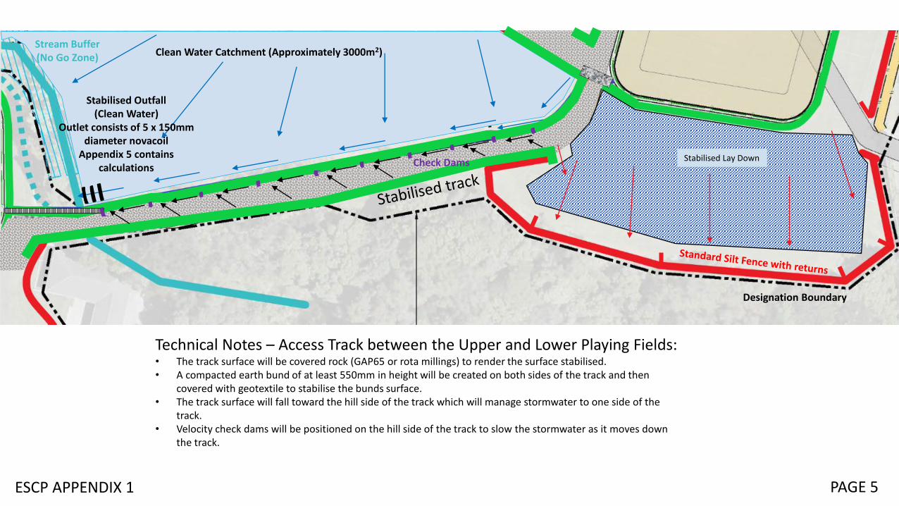
Technical Notes – Access Track between the Upper and Lower Playing Fields:• The track surface will be covered rock (GAP65 or rota millings) to render the surface stabilised.• A compacted earth bund of at least 550mm in height will be created on both sides of the track and then
covered with geotextile to stabilise the bunds surface.• The track surface will fall toward the hill side of the track which will manage stormwater to one side of the
track.• Velocity check dams will be positioned on the hill side of the track to slow the stormwater as it moves down
the track.
PAGE 5ESCP APPENDIX 1
Stabilised Lay Down

Stabilised Outfall(Clean Water)
Stabilised track
Clean Water CatchmentStream Buffer(No Go Zone)
Technical Notes – Clean Water Diversion outfall:• Stormwater from the track surface will be
directed through a 300mm diameter culvert across the area of the stream to enter into the stockpile bunding that delivers stormwater to SRP1.
• The upper part of the track will be shaped to direct off to the silt fences associated with the Upper Playing Field.
• To introduce clean stormwater into the stream at the bottom of the track without causing scour to the stream bed or stream bank a coffer dam will be constructed adjacent the stream and water will be dropped into the stream using novacoilpipes.
• To avoid the existing stream culvert an overland pipe culvert (300mm diameter), similar to that shown in the photo will be used to transfer the dirty water to the proposed bund surrounding the stock pile.
PAGE 6ESCP APPENDIX 1 Example only of the pipe structure to be employed
Stream inside existingculvert under track
Direction of flow

PAGE 7ESCP APPENDIX 1

Technical Notes –Watermain Installation:• The Watermain needs to
be installed prior to the stockpile area becoming available to receive material from the reservoir excavation area.
• The area involved is flat with a very slight fall toward the East
• Silt fencing will encircle the area to be used as a stock pile for excavated material.
• Large volumes of ground water entering the trench are not anticipated. Any water encountered will be allowed to drain away within the trench or alternatively pumped out of the trench adjacent the work site and allowed to flow overland to the area protected by the silt fence some 40-50m away.
PAGE 8ESCP APPENDIX 1
Access Bunding (transversible)(Barrier to stormwater exitingthe excavation area)

PAGE 9ESCP APPENDIX 1
Discharge point for SRP1
Discharge point for SRP2
SRP1
SRP2
Technical Notes – Discharge Points associated with SRPs:• Primary outlet pipes will be directly connected to the stormwater network and buried.• Emergency spillway will be overland within a confined flow path to the same stormwater network only it will enter via a connection through the
manhole (diameter 500mm).• SRP1 it discharges into the piped section of the Papawai Stream approximately 100m away and SRP2 discharges into the piped section of the
Waitangi Stream that discharges into the harbour after several kilometres. The pipes at 375mm diameter concrete at the point of entry.