standard of care: physical therapy management of the ...€¦ · physical therapy management of the...
TRANSCRIPT

Standard of Care:
Physical Therapy Management of the Patient with a Mechanical Circulatory Support Device
Copyright © 2015 The Brigham and Women's Hospital, Inc., Department of Rehabilitation Services. All rights reserved.
BRIGHAM AND WOMEN’S HOSPITAL Department of Rehabilitation Services
Physical Therapy
Standard of Care:
Physical Therapy Management of the Patient with a Mechanical Circulatory
Support Device
ICD 10 Codes1:
I 20- I 25 Ischemic Heart Disease I 40 – I 41 Acute Myocarditis
I 42- I 43 Cardiomyopathy
I 46 Cardiac Arrest
I 50 Heart Failure
Case Type / Diagnosis:
This standard of care applies to patients who have undergone placement of a mechanical circulatory support device (MCSD), including ventricular assist devices (VAD) or total artificial heart (TAH) for end-stage heart disease. End stage heart disease is a growing problem in America and advanced disease has a mortality rate of one in five persons in the first year. Seventy-five percent of people with symptomatic heart failure have moderate to severe diastolic
dysfunction and one in four death certificates list heart failure as the reason of death.2,3
There were over 1 million hospital discharges related to heart failure in 2013 and the estimated cost of
heart failure in 2013 was 39.2 billion dollars in the US.2,3
Despite advances in medical management, heart transplantation remained the only option for many patients. Due to long waiting lists for organs, the National Heart, Lung and Blood Institute urged the development of cardiac mechanical assist devices in the 1970’s. Since then, many devices have been developed
and can be used for short or long term support.4
Ventricular assistive devices are used for refractory heart failure or cardiogenic shock,
both of which can result from acute or chronic health conditions, including acute myocardial
infarction, myocarditis, or progressive end stage heart failure. A VAD can be used to support the
left ventricle (LVAD), the right ventricle (RVAD) or both ventricles (BiVAD). In 2013, there
were 2,365 LVADs implanted, compared to the 247 implanted in 2007.5
Devices can be described in many ways including location of the pump or the
mechanism of pumping. Pumping chambers can be located inside the body (called
intracorporeal devices) or outside the body (called extracorporeal or paracorporeal devices).
Furthermore, devices can be pulsatile or non-pulsatile. A pulsatile pumping mechanism has a
sac and diaphragm which create a compressible blood chamber. The chamber expands to fill
when blood enters it, and is emptied when compression of the diaphragm is triggered. This type

Standard of Care:
Physical Therapy Management of the Patient with a Mechanical Circulatory Support Device
Copyright © 2015 The Brigham and Women's Hospital, Inc., Department of Rehabilitation Services. All rights reserved.
of device has valves which control blood flow to maintain forward flow of blood. Pulsatile
VADs can be controlled by an electric motor or a pneumatic hand pump, in the case of VAD
electrical malfunction. Non-pulsatile VADs are divided into axial flow pumps in which a
propeller propels blood unidirectionally, and centrifugal pumps in which blood comes into the
center of the pump, and is spun and accelerated out to the periphery of the plate.6
For all
devices, the inflow cannulae bring blood from theperipheral circulation of the body to the
VAD. Inflow cannulae remove blood from the atria or ventricle and decrease preload. The
outflow cannulae bring blood from the VAD back to the body. In the case of the RVAD, the
blood returns to the body via the pulmonary artery. In the case of an LVAD, the blood returns
to the body via the aorta and provides or supplements cardiac output.6
With BiVAD support,
both ventricles are supported.
The TAH is a pulsatile, biventricular pneumatically driven orthotopic device that is used
as a bridge to cardiac transplant in patients who are at risk of imminent death7
due to
biventricular failure. Biventricular failure can occur due cardiogenic shock as a result of acute
myocardial infarction, advanced heart failure including ischemic and non-ischemic
cardiomyopathy along with transplant rejection and VAD failure. With the TAH, both native ventricles and all four native heart valves are replaced by
artificial ventricles and tilting disc valves, respectively.8
The artificial ventricles have inner diaphragms that are surrounded by a more supportive, rigid casing. Blood enters the artificial right ventricle from the native right atrium and partially fills before fully ejecting through a short outflow cannula grafted to the pulmonary artery. Blood returns from the lungs into the left atrium, flows into the artificial left ventricle, and when it is partially filled, is fully ejected into an outflow cannula grafted to the aorta to provide systemic circulation. The pneumatic driver delivers pulses through the drive lines into the air chambers of the ventricles to distend the diaphragms and trigger ejection of the blood. In each cycle, ventricles have the capacity to fill up
to 70 mL with output of up to 9.5L/min.9
The indication for which design and brand of MCSD is placed is patient or surgeon
specific. In general, short term devices are placed for patients who are likely to have a rapid
recovery, termed “bridge to recovery” or to stabilize them for another intervention to increase
heart function, termed “bridge to decision”. These devices are used for a few days to a few
months. Long term devices can be used for several months to years. These devices are often used
as a “bridge to cardiac transplantation” if it is determined that the patient is a good candidate, or
as an alternative to cardiac transplantation as end of life care, called “destination therapy.”6
Brigham and Women’s Hospital currently uses VADs made by Thoratec Corporation (PVAD®,
IVAD®, Heartmate I
®, Heartmate II
®, Centrimag
®), CardiacAssist, Inc. (TandemHeart
®),
HeartWare®
(HVAD®) and SynCardia (TAH-t Temporary Total Artificial Heart). For specific
information about each device, please see appendixes A through F.

Standard of Care:
Physical Therapy Management of the Patient with a Mechanical Circulatory Support Device
Copyright © 2015 The Brigham and Women's Hospital, Inc., Department of Rehabilitation Services. All rights reserved.
Indications for Treatment10
: The following structural and functional changes may be present after VAD placement
1. Body Structures
a. Heart (s4100)
b. Arteries (s4101)
c. Veins (s4102)
d. Capillaries (s4103)
e. Trachea (s4300)
f. Lungs (s4301)
g. Thoracic Cage (s4302)
h. Muscles of Respiration (s4303)
i. Skin Of Trunk And Back (s8105)
j. Skin of Upper Extremity (s8102)
k. Skin Of Lower Extremity (s8104)
2. Body Functions
a. Heart Functions (b410)
b. Blood Vessel Functions (b415)
c. Blood Pressure Functions (b420)
d. Respiratory Functions (b440)
e. Respiratory Muscle Functions (b445)
f. Additional Respiratory Functions (b449)
g. Exercise Tolerance (b455)
h. Energy and drive functions (b130)
i. Immunological system functions (b435)
j. Ingestion functions (b510)
k. Urinary excretory functions (b610)
l. Mobility of joint functions (b710)
m. Muscle power functions (b730)
n. Repair functions of the skin (b820) 3. Activity and Participation
a. Carrying out daily routine (d230)
i. Managing one’s own activity level (d2309)
b. Handling stress and other psychological demands (d240)
c. Speaking (d330)
d. Change basic body position (d410)
e. Maintaining a body position (d415)
f. Transferring oneself (d420)
g. Walking (d450)
h. Caring for body parts (d520)
i. Dressing (d540)
j. Intimate relationships (d770)

Standard of Care:
Physical Therapy Management of the Patient with a Mechanical Circulatory Support Device
Copyright © 2015 The Brigham and Women's Hospital, Inc., Department of Rehabilitation Services. All rights reserved.
k. Work and employment (d845)
l. Community life (d910)
m. Recreation and leisure (d920)
n. Sound (e250)
o. Air quality (e260)
p. Support and relationships
i. Immediate family (e310)
ii. Friends (e315)
q. Individual attitudes of friends (e420)
Contraindications / Precautions for Treatment:
The most common medical and surgical complications associated with VAD therapy include
hemorrhage, hemolysis, thrombosis, stroke, infection, device malfunction, arrhythmias, renal
dysfunction, hypotension, respiratory dysfunction and hepatic dysfunction.9,11
When only one
ventricle of the heart is supported (i.e. LVAD) there is the potential for contralateral ventricular
failure.6,7
Please refer to the cardiac standard of care for general precautions and
contraindications for treatment of the cardiac surgery patient.
Sternal precautions apply for all patients who have had a midline sternotomy.
Refer to the cardiac standard of care for specific precautions.
Physical therapy (PT) intervention may need to be modified in the following situations:
Infections tend to occur early in the VAD course, generally developing in the first 2
months after implantation. A study of 4,124 patients following discharge from an acute
care setting reported that 1,253 (30%) had major infections. Of those 1,253 patients
42.1% were related to localized (non-device) related infection, 41.2% were related to
site/pocket infection, and 16.2% were related to sepsis.12
The most common organisms found in VAD related infections include coagulase-negative staphylococci, S. aureus,
Enterococcus species, gram-negative bacilli and Candida.13
Infections are evidenced by fevers, increased white blood cell counts and radiographic evidence on chest or abdominal CT scan. Infections may be difficult to diagnose and may lead to increased
bleeding and thrombotic complications.12
Arrhythmias, specifically atrial fibrillation and ventricular tachycardia, may not be an absolute contraindication to PT treatment. Ventricular tachycardia may be treated with antiarrhythmic medications in the case of an LVAD. In the case of a biventricular
assistive device, arrhythmia may be well tolerated by the patient.14,15
Conversations with the medical team or nurse regarding the physiologic and hemodynamic status of the
patient may be necessary. Staff should monitor for symptomatic response to arrhythmia
or hemodynamic instability/intolerance.
Thrombotic related events including neurological dysfunction, pump thrombosis or
hemolysis can occur following VAD implant.12

Standard of Care:
Physical Therapy Management of the Patient with a Mechanical Circulatory Support Device
Copyright © 2015 The Brigham and Women's Hospital, Inc., Department of Rehabilitation Services. All rights reserved.
Orthostatic hypotension can often manifest itself through 1) a rise in native heart rate or
VAD rate, 2) a drop in systolic blood pressure or mean arterial pressure (MAP), 3) a drop
in VAD flow, 4) a decrease in VAD pulsitility index, or 5) a drop in TAH fill volume
and/or cardiac output depending on device in use. Treatment considerations are similar to
any patient with hypotension and include the use of lower extremity compression
garments (i.e. antiembolism stockings, elastic wrap bandages), abdominal binders, deep
breathing, lower extremity exercise and supine repositioning with lower extremity
elevation.
Any new VAD alarms or VAD malfunction
Anticoagulation during long term VAD therapy is essential for prevention of thromboembolic and bleeding complications. The International Normalized Ratio (INR) goal will depend on the type of device and the patient’s past medical history, and should
be discussed with the VAD healthcare team.16
Partial thromboplastin time (PTT) should also be monitored while patients are on Heparin for short term anticoagulation.
Initial Mobility Considerations:
When mobilizing patients early in their recovery, while they are in the cardiac ICU, it is
important to monitor all lines and tubes, paying special attention to pulmonary artery
(Swanz-Gans) catheter and left atrial catheter restrictions. Close monitoring of all vital
signs and MCSD numbers is also very important.
Cardiopulmonary resuscitation (CPR) may or may not be effective in the patient with a VAD.
Please refer to appendices A through F for device specific emergency procedures.
Many device-specific precautions and contraindications also exist within the VAD population.
Please refer to appendices A through F for device-specific precautions and contraindications.
Evaluation: 1. Medical History:
a. Cardiac risk factors
b. Onset and duration of cardiac symptoms
c. Cardiac Diagnosis
d. Length of cardiac history
e. Extent of prior cardiovascular interventions
2. History of Present Illness: Include if the MCSD was placed emergently or electively, the
type of MCSD placed, which ventricle(s) is/are supported, manufacturer, goal of MCSD
therapy (i.e. destination therapy, bridge to transplantation), complications during the
perioperative or postoperative period, pertinent lab values, significant diagnostic tests, dates
of physical and occupational therapy (OT) consults, date of abdominal binder fitting by OT,
and any response to activity with RN/medical staff (i.e. flows drop with bed mobility, etc.)

Standard of Care:
Physical Therapy Management of the Patient with a Mechanical Circulatory Support Device
Copyright © 2015 The Brigham and Women's Hospital, Inc., Department of Rehabilitation Services. All rights reserved.
3. Social History: Patient’s prior level of function, prior use of an assistive device, level of
endurance, home environment, barriers, family/caregiver support available, patient’s
expectations of returning to home and their life goals.
4. Medications: a. Medications on admission (i.e. home inotropic support) b. Medication requirements perioperatively, including vasopressors, beta blockers, ACE
inhibitors, calcium channel blockers, diuretics, and pain medications
c. Current medications
d. Medication effects on rehabilitation therapies
Examination: Please refer to the Cardiac Medicine & Surgery Standard of Care for all examination techniques related to the general cardiac patient.
1. Observation
2. Hemodynamics: A patient’s native heart rate will be demonstrated on telemetry unless the
patient has a TAH in which case the rate is set by the device. The therapist should note this
rate, but be aware that the VAD rate will be different and is a more reliable rate for the
patient’s status as it directly controls all peripheral flow and cardiac output. Taking a radial
pulse will monitor peripheral flow, and will therefore be a reflection of VAD rate in a patient
with a pulsatile device. A pulse oximeter will also reflect VAD rate, not the native heart rate. A
pulse oximeter will not be able to detect VAD rate or oxygen saturation in a patient with a
pulseless device. In axial flow pumps, BP is often difficult to auscultate. In the ICU, BP may
be monitored with an arterial line, however once the arterial line is discontinued, the standard
of care is to monitor mean BP by Doppler.17
In patients with a pulsatile device, BP can be
measured via sphygmomanometer and stethoscope. Not that there may be a blunted BP
response to exercise in patients with TAH.
3. Current Lab Values
4. Abdominal Binder: All patients should be fitted with a binder by OT prior to initiation
of out of bed activities. This binder may be custom made, or a prefabricated binder issued by
any of the MCSD companies. The binder provides immobilization of the percutaneous drive
line to promote wound healing between the epithelium and the fabric of the driveline, and
prevent infection.20
The binder should be worn at all times, including
during sleep.20
Ensure proper binder fit and adequate security of drivelines prior to
mobility.
5. Power Source: The patient’s MCSD may be connected to a power based unit (i.e. AC power
from wall source) or may be reliant on battery support. It is important to know the current
battery life of the MCSD prior to initiation of physical therapy services. See
appendices for specific instructions on different devices
6. Pain: (location, duration, intensity), use of Visual or Verbal Analog Scale 0-10,21
and any
action taken (i.e. RN notified of patient’s pain, patient pre-medicated)
7. Posture

Standard of Care:
Physical Therapy Management of the Patient with a Mechanical Circulatory Support Device
Copyright © 2015 The Brigham and Women's Hospital, Inc., Department of Rehabilitation Services. All rights reserved.
8. Sensation
9. Strength/Muscle Performance
10. Range of Motion
11. Functional Mobility a. Patients should be progressed as with any acute care patient. Early mobilization of patients,
including positioning, bed mobility and transfers should be initiated as early as post-operative day 1 in the intensive care unit pending medical stability.
22,23
b. Current recommendations suggest that patients with VADs should be out of bed to
chair and beginning ambulation with assistance by postoperative days 3-5.24
It is suggested that patients with VADs should progress to independent ambulation and
stair climbing with physical therapy by postoperative days 12-14.24
12. Gait: Note if the patient is ambulating on battery support or with a AC power based unit, and
note if the patient is pushing their own MCSD or if they need assistance
13. Endurance
a. Rate of Perceived Exertion15
is an effective method of determining exercise
parameters in correlation with vital sign and MCSD response
b. Six Minute Walk Test25,26
can be initiated in the patient with a VAD as medically
appropriate. The percent of age predicted walking distance per Enright et.al. or
Gibbons et.al. should be recorded in the medical record.27,28
c. Current literature suggests that an endurance program for a patient with a VAD should
include the following:
i. Interval ambulation (i.e. 2 min x5) initiated by postoperative days 9-11.24
ii. A treadmill walking program by days 12-14 prescribed by modified
treadmill ramp protocol depending on the device and patient’s level of
medical stability.24,29
iii. Cycling, which may begin by postoperative week 3, should begin with 50
watts and increased by 25 watts as tolerated by patient
iv. Exercise should be progressed by 5 minutes each week for a total of 50
minutes of exercise 4-5 times per week by postoperative week 6.24
14. Balance: Note alterations in balance when on battery power or when pushing a portable
driver
15. Positioning: Including drive lines and abdominal binder.20
16. Skin Integrity: a. Surgical wound appearance and driveline sites, skin breakdown from prolonged
immobility pre and post-op.
17. Lines and Tubes:
a. MCSD drive lines,20
location of inflow and outflow cannulas (external device),
attachment to AC or battery power
b. Peripheral IV lines, Internal Jugular IV lines, Central IV lines, Pulmonary Artery
(Swanz-Gans) line, Left Atrial line, nasogastric tube, chest tubes, telemetry, Foley
catheter, rectal tube, oxygen delivery, Velitri
i. Be aware of mobility restrictions for those who continue to have a PA or

Standard of Care:
Physical Therapy Management of the Patient with a Mechanical Circulatory Support Device
Copyright © 2015 The Brigham and Women's Hospital, Inc., Department of Rehabilitation Services. All rights reserved.
LA line.
18. Cognitive-Perceptual and Psychological Considerations: If the patient has undergone
elective MCSD placement, a pre-operative cognitive evaluation is often completed by the
occupational therapist (OT), and can be helpful in post-operative management and
education30
a. The psychological implications of MCSD placement: note the patient’s ability to cope
with body image changes, altered functional status, fear or anxiety regarding the
mechanical device, fear of upcoming transplant, fear or anxiety around retuning to
previous life roles, burden of awaiting transplant and end of life issues. b. Consider the patient’s goals and motivators, the patient’s learning style and preferred
method of information delivery. There are many forms of MCSD education including
videos, books, one-on-one conversation with the MCSD nurse practitioner and hands-on
practice with supervision from the nurse or nurse practitioner.
c. Family stress, major depression, organic mental syndromes and serious adjustment
disorders occur more frequently in patients with medical complications and
significantly impairs rehabilitation. Aggressive treatment of depression in the MCSD
patient may improve functional status.4
d. Note any cognitive changes related to peri-operative or post-operative
neurological events as described above as potential complications.
Assessment: The primary goal for inpatient physical therapy for a patient status post VAD placement is to maximize the patient’s functional independence and safety prior to discharge from the hospital.
If discharge home is not feasible, the goal of inpatient physical therapy intervention is to
maximize their independence and endurance while on VAD at Brigham and Women’s Hospital
prior to discharge to discharge to a local extended care facility specifically trained to care for
patients with VADs. Brigham and Women’s Hospital has partnered with Spaulding Hospital and
Rehabilitation Center in Cambridge to provide continued rehabilitative services after discharge
from the acute care setting. If patient remains in house following MCSD implantation while
awaiting heart transplant, goal is to optimize physical functioning and endurance in anticipation
of cardiac transplant.

Standard of Care:
Physical Therapy Management of the Patient with a Mechanical Circulatory Support Device
Copyright © 2015 The Brigham and Women's Hospital, Inc., Department of Rehabilitation Services. All rights reserved.
Body Changes Potential body structure changes include, but are not limited to: median sternotomy, integumentary incisions, and cardiovascular and pulmonary system deconditioning.
Potential body function changes may include, but are not limited to, cardiac and
pulmonary pumps, aerobic capacity/activity tolerance, circulation, muscle performance,
balance, and knowledge related to incisional precautions as well as knowledge regarding
the operations of the MCSD, and recommendations regarding mobilizing and exercising
with the new MCSD.
Prognosis The predicted optimal level of improvement for these patients is to return to their home environment demonstrating independence in all areas of function including gait with the
MCSD, with assistive devices as needed, and independence with management of their
MCSD device at rest and during daily activities and exercise. Patients should be able to
return to their previous roles & lifestyles, although some modifications will likely be
necessary because of the MCSD. It is reasonable to expect patients to be at their
maximum level of independence within 6-8 weeks of MCSD placement. This prognosis
may be altered in the event of any comorbidities, complications or secondary
impairments. Environmental factors such as home set up, and psychosocial consideration
such as their available support network will also impact home management of the MCSD,
and may alter functional capacity and participation. At Brigham and Women’s Hospital
the post- VAD median length of stay was 20 days in 2008. A recent study published in
2014 determined that early mobilization in patients with LVAD implantation was a good
predictor of shorter length of stay in the hospital along with discharge home versus
another acute setting. Of the 98 patients in the study, the mean length of stay was 35.4
days, 67 discharged to home settings, 22 discharged to rehab settings and 9 patients died.
Of the 67 that discharged to home, the mean length of stay was 29.9 days and the average
amount of days until first ambulation post implant was 4.1 days (compared to the 21.2
days for those who went to rehab). In addition, at time of discharge, approximately 84
percent of patients who were able to go home were able to ambulate with less than
minimal assistance, compared to the 21 percent of patients discharged to rehab who were
able to ambulate with less than minimal assistance.5
Goals: Potential goals for safe discharge home:
Body Structure/Function:
The patient will demonstrates range of motion within functional limits in bilateral upper
extremities and lower extremities.
The patient will demonstrate upper and lower extremity strength to maximal ability within their
sternal precautions

Standard of Care:
Physical Therapy Management of the Patient with a Mechanical Circulatory Support Device
Copyright © 2015 The Brigham and Women's Hospital, Inc., Department of Rehabilitation Services. All rights reserved.
Activity:
The patient will be independent in all functional mobility including bed mobility, transfers,
ambulation and stair training with their VAD
The patient will be independent in all VAD management and monitoring during functional
activities
Participation:
The patient will be independent in all VAD management and monitoring during an independent
exercise program
The patient will utilize VAD support group for support with community reintegration
Treatment Planning / Interventions
Established Pathway ___ Yes, see attached. X No
Established Protocol ___ Yes, see attached. X No
Interventions most commonly used for this case type/diagnosis.
This section is intended to capture the most commonly used interventions for this case type/diagnosis. It is not intended to be either inclusive or exclusive of appropriate interventions.
Physical Therapy is typically consulted to see the VAD patient immediately post-operatively. It
is the therapist’s responsibility to assess each patient’s appropriateness for beginning a PT
program. Patients who have undergone VAD placement are typically seen for the following
interventions:
Therapeutic Exercises: Physical Therapy with a VAD patient often begins in the ICU with
passive or active assisted ROM exercises, advancing to active ROM exercises as the patient’s
strength improves. Exercises typically progress from supine, to sitting, to standing. Patients are
issued a Phase One Cardiac Rehab Exercise program which includes a daily walking and
therapeutic exercise program.
Endurance Training: Systemic cardiac output has been shown to increase after LVAD
implantation because the left ventricle is able to eject blood through the native aortic valve and
increase blood output in parallel with the VAD.31,32
Endurance training is accomplished by
gradually increasing the time patients are able to participate in an activity. This is usually
addressed initially through the progression of functional activities, gradually increasing the time
the patient is out of bed to a chair or the distance a patient is walking. Stationary biking and
treadmill use with close monitoring is also an option; however the position of the VAD may
interfere with the ability to perform full hip flexion to allow for comfortable pedaling. Use of a
restorator may be more practical in the VAD patient. Interval training is often utilized with

Standard of Care:
Physical Therapy Management of the Patient with a Mechanical Circulatory Support Device
Copyright © 2015 The Brigham and Women's Hospital, Inc., Department of Rehabilitation Services. All rights reserved.
exercises, functional activities or ambulation to increase endurance. In some cases, endurance
and interval training via a treadmill protocol may be indicated.
Functional Mobility Training: Patients are progressed from bed mobility, to sit to stand and bed
to chair transfers, to ambulation, to weaning assistive devices as appropriate, and finally to
steps/stairs; all with independent management of their devices.
Mechanical Circulatory Support Device Management: During the course of physical therapy
interventions, the patient and therapist should focus on increasing the patient’s independence
with the mechanical features of the MCSD. The patient should progress to efficiently changing
from AC to battery power, performing system checks, packing their “emergency” bag for
ambulation and monitoring MCSD hemodynamic response to activity. The patient may have to
learn special techniques for maneuvering the MCSD on the stairs and monitoring their exercise
tolerance when conventional techniques do not apply. The patient will review emergency
techniques with the nurse or nurse practitioner and should be proficient in these techniques with
appropriate clinical documentation before being encouraged to ambulate independently by the
therapy staff.
Frequency & Duration: Frequency may vary during the patient’s hospital course. Initial
treatment in the ICU is often 3-5x/wk with frequency progressing to 5-7x/wk as discharge
approaches. If the patient remains at BWH until transplant, their frequency of treatment may
lessen as they achieve their PT goals and continue to be followed for optimization of
endurance and function leading to transplant. They may be discharged from acute PT services
and perform an independent program daily, with supervision as needed from the nursing staff
or their family while they remain at BWH.
Patient / family education
o Instruct patient in appropriate pacing techniques o Instruct patient about sternal precautions o Patients should be taught to understand their own MCSD numbers at rest, and
how they should respond to daily activities, self care and exercise
o In conjunction with the MCSD team, review with the patient how to check their
battery life prior to mobilization
o In conjunction with the MCSD team, review emergency equipment and
procedures
o Review equipment that should be carried with them during ambulation or time out
of their room
o Instruct patient in independent therapeutic exercise program o Instruct patient in home exercise/activity program including a therapeutic exercise
program and a cardiopulmonary endurance program (walking, biking)
o MCSD patients who experience abdominal discomfort related to the MCSD may
benefit from education regarding stretching, positioning, and bracing in the
abdominal region

Standard of Care:
Physical Therapy Management of the Patient with a Mechanical Circulatory Support Device
Copyright © 2015 The Brigham and Women's Hospital, Inc., Department of Rehabilitation Services. All rights reserved.
Handouts BWH Guidelines after Cardiac Surgery BWH VAD Handbook (created by VAD Nurse Practitioners, supplemented by PT and OT)
Recommendations and referrals to other providers Treatment of the VAD patient is a multidisciplinary approach with a specialized group of cardiologists, cardiac surgeons, and nurse practitioners. Referrals to other disciplines at BWH often include:
Occupational Therapy (OT): OT is often consulted pre-operatively to assess cognitive function
and ability to learn in the case of elective MCSD placement. Long term low cardiac output in the
heart failure patient impacts end organ function through decreased blood flow. Studies have shown moderate to severe cognitive and neuromotor impairment in up to 60% of patients with heart failure. These patients can show impairments in mental processing speed, memory, motor speed and grip strength. More pronounced levels of these impairments were noted in the patients
who required mechanical assist devices30
. Hand weakness and dyscoordination may lead to
difficulty in independent manipulation of MCSD parts. This can often be identified and treated
by an occupational therapist prior to elective MCSD surgery with an independent exercise
program. OT is also consulted immediately post-operatively for all MCSD patients to measure
the patient for a custom made or prefabricated abdominal binder. A full OT evaluation is
completed once the patient is medically stable to assess upper extremity motor skills, ADLs and
cognitive skills.33
In a recent study, VAD patients have reported difficulties performing self-care
activities which OTs at Brigham and Women’s Hospital routinely assess during evaluation and
treatment sessions.34,35
Social work: At BWH there is a specific social worker who specializes in the care of patients in
the heart failure program. The social worker follows these patients during admissions for heart
failure, admissions for MCSD placement and any subsequent admissions, up to and including
admissions around cardiac transplantation if applicable.
Chaplaincy and/or Psychiatry may need to be involved in the treatment of this patient population
due to the severity of the patient’s illness, the effect on family dynamics, body image, life roles
and potential end of life issues. Shapiro, et al noted that psychiatric problems most often
occurred in patients who had complications following VAD placement, and that aggressive
treatment of depression may help improve functional status.4
Speech and Swallow Services: Speech and swallow therapy may be involved in patients who
present with significant weakness related to preoperative heart failure, long intubations and bed
rest. A bedside speech evaluation will be completed to determine appropriateness of a video
swallow evaluation, prior to initiating food/liquid by mouth. Speech Therapy can also provide
assistance with speech and language in the event of a perioperative CVA.

Standard of Care:
Physical Therapy Management of the Patient with a Mechanical Circulatory Support Device
Copyright © 2015 The Brigham and Women's Hospital, Inc., Department of Rehabilitation Services. All rights reserved.
Care Coordination: The cardiac surgery care coordinators aid in setting up home care services
when the MCSD patient nears discharge home. Home nursing services are initially needed for
dressing changes and blood draws. The care coordinators can also set up transfer to Spaulding
Hospital for Continuing Medical Care in Cambridge, Massachusetts.
VAD/MCSD Support Group: Support group meets twice a month. Patients generally come to the
BWH VAD clinic and meet with their doctors and nurses in the morning, followed by support
group in the early afternoon. The social worker runs the support group, and the VAD nurse or
nurse practitioners (NPs) are generally present. Many current VAD patients, and occasionally
some heart transplant patients who have had VADs in the past, are involved in the support group.
The group is open to all current VAD patients, whether inpatient or outpatient, and their families.
Often times a patient may still be in the ICU, but the family members are able to begin
participating in support group. All inpatients are encouraged by the VAD team to attend when
hemodynamically stable. Rehab therapists schedule treatment sessions around the meeting of
support group, as attending support group is considered a vital part of the VAD program and the
patients overall recovery process. Supportive care by social workers and mentoring by prior VAD patients in a support group has been suggested as a way to improve quality of life in the
weeks following VAD implantation.34, 35
Re-evaluation/Re-assessment Reassessment will occur every 7-10 days following initial evaluation or most recent assessment, but may also occur due to any of the following circumstances: all physical therapy goals are met,
there is a significant change in the patient’s medical status, the patient is discharged from acute
PT services, or the patient is discharged from Brigham and Women’s Hospital.
Discharge Planning Discharge planning for the MCSD patient is a multidisciplinary approach. The patient going home with a new MCSD has to demonstrate knowledge of handling the device on a daily basis
and in emergency situations to the MCSD team. Their family members/caregivers must also
be able to demonstrate these procedures before the patient can safely be discharged from
BWH. The MCSD team provides education regarding operation of the MCSD, troubleshooting
alarms, exit site wound care, and post discharge follow up care. Community support for
medical or power failure emergencies is necessary when a MCSD patient goes home. The
patient’s local fire departments, emergency medical technicians (EMTs), and emergency room
physicians are trained in emergency procedures of the MCSD by the team. The local power
company is also alerted to the need for early return of power in the case of power loss. VAD
patients’ perceptions of being unable to care for themselves after surgery may be alleviated
with educational programs as mentioned above.34, 35
The uncomplicated VAD recipient is discharged to home within weeks of VAD placement,
however many times their hospital course may be extended due to complications. Upon
discharge from BWH, most individuals do not require follow-up physical therapy. Patients have

Standard of Care:
Physical Therapy Management of the Patient with a Mechanical Circulatory Support Device
Copyright © 2015 The Brigham and Women's Hospital, Inc., Department of Rehabilitation Services. All rights reserved.
been instructed in their individualized home exercise program, including a cardiopulmonary
endurance training program. They have also been instructed in the correct way to advance their
own program, and will therefore be able to progress on their own. The VAD team is readily
available to these patients if they have any questions. The services of home physical therapy can
be available as needed through many homecare agencies.
In the event that a patient with a MCSD is unable to be discharged home due to functional
limitations and/or medical complexity, Brigham and Women’s Hospital has a working
relationship with Spaulding Hospital for Continuing Medical Care in Cambridge, Massachusetts.
It should be discussed as early as possible with the healthcare team should the need for a rehab
stay be anticipated. In the case of discharge to Spaulding Hospital for Continuing Medical Care
in Cambridge, the MCSD team coordinates staff education at the receiving hospital, and the
Cardiac Surgery Care Coordinator facilitates discharge arrangements. Complex MCSD discharge
situations should be discussed with a mentor therapist and the MCSD team.
Patient’s discharge instructions Patients are discharged from physical therapy services when they have met all short term goals for safe discharge home. Patients may require assistance from their families or caretakers with
MCSD management, and physical therapists should take this into consideration when creating
patient goals. A family teaching session prior to discharge from physical therapy services is
generally warranted for patient and family safety. Patients must also demonstrate competence in
monitoring the MCSD during exercise and demonstrate appropriate modifications of their
exercise program based on their response to exercise.
Patients and their families are discharged home after extensive teaching with the MCSD team.
The nurse practitioners will complete the majority of discharge teaching, and the nursing staff
will reinforce the teaching on a daily basis. Some discharge teaching may be done with the
physical therapist, but great care should be taken to ensure accuracy and consistency of
information. The patient will receive a MCSD log book prior from the team prior to discharge
home. Each log book is device specific and includes emergency contact information, a
troubleshooting guide, the device manual, flow sheets for tracking MCSD numbers, a medication
flow sheet, flow sheets for tracking weight, blood pressure and temperature, and wound care
information. Information from other disciplines (i.e. PT, OT and nutrition) will also be included.
The log book also includes a discharge checklist which should be completed by the nurse
practitioner prior to discharge to ensure that all necessary information is covered. Physical
therapy should provide any necessary exercise and sternal precaution handouts and pertinent
contact information.
Author: Reviewed by:
P. Newman, PT J. Rydingsward, PT
03/2015 M. Tagerman, PT
N. Russell, PT

Standard of Care:
Physical Therapy Management of the Patient with a Mechanical Circulatory Support Device
Copyright © 2015 The Brigham and Women's Hospital, Inc., Department of Rehabilitation Services. All rights reserved.
BRIGHAM AND WOMEN’S HOSPITAL Department of Rehabilitation Services
Physical Therapy
Standard of Care: Mechanical Circulatory Support Device
Appendix A
Thoratec® PVAD
TM and TLC II
® Portable Driver
Reprinted with permission from Thoratec Corporation
Indications for use
Left, Right, or Biventricular failure
Lethal arrhythmias
Bridge to transplant or post-cardiotomy recovery
Those who do not qualify for other devices due to:
o Small body habitus- less than 1.5m2, but larger than 0.73m
2 body surface area
(BSA)
o Mechanical Aortic Valve

Standard of Care:
Physical Therapy Management of the Patient with a Mechanical Circulatory Support Device
Copyright © 2015 The Brigham and Women's Hospital, Inc., Department of Rehabilitation Services. All rights reserved.
Paracorporeal VAD (PVADTM
)
Paracorporeal device that can centrally or peripherally cannulated
A prosthetic ventricle with smooth chamber enclosed in a hard case
Two mechanical valves maintain unidirectional flow
The pumping chamber is separated from an air chamber by a polyurethane diaphragm
The fill switch determines when the VAD is full of blood and sends the fill signal to the
drive console
Figure 1
Thoratec® PVAD
TM Reprinted
with permission from Thoratec
Corporation
Support & Cannulation (Figure 2)
Can provide left, right or biventricular support
In left heart support the inflow cannula allows blood to travel from the left atrium or the
left ventricle into the pump, and the outflow cannula allows blood to travel from the
pump and out to the aorta
In right heart support the inflow cannula allows blood to travel from the right atrium into
the pump, and the outflow cannula allows blood to travel from the pump and out to the
pulmonary artery
Figure 2
Examples of Cannulation
Reprinted with permission from
Thoratec Corporation

Standard of Care:
Physical Therapy Management of the Patient with a Mechanical Circulatory Support Device
Copyright © 2015 The Brigham and Women's Hospital, Inc., Department of Rehabilitation Services. All rights reserved.
With atrial cannulation, there is minimal myocardial damage and cardiopulmonary bypass
is not necessary, but lower VAD flows are achieved
With ventricular cannulation, there are higher VAD flows and lower risk of
thromboembolism
Dual Driver Console (DDC) (Figure 3)
Contains two identical, independent drivers labeled LVAD and RVAD if the patient is on
biventricular support
Modes are “asynchronous” or “volume”
o “Asynchronous” mode allows a set rate o “Volume” mode allows the VAD chamber to empty only when completely filled
with blood (variable rate)
Percent systole is the ejection time (in milliseconds) the VAD takes to eject the
blood (i.e. 300 milliseconds)
Drive Pressure: Ejects blood from the VAD
o LVAD 230-245mmHg o RVAD 140-160mmHg
Vacuum: Assists with VAD filling, generally -25 to -40 mmHg
Figure 3
Dual Driver Console
Reprinted with Permission from
Thoratec Corporation

Standard of Care:
Physical Therapy Management of the Patient with a Mechanical Circulatory Support Device
Copyright © 2015 The Brigham and Women's Hospital, Inc., Department of Rehabilitation Services. All rights reserved.
DDC Alarms
Pressure Alarm
o Occurs when ejection pressure is below 100mmHg or above 250 mmHg o If alarm sounds during PT treatment, notify VAD team
Vacuum Alarm
o Occurs when vacuum is less than +4 mmHg or greater than -90mmHg o If alarm sounds during PT treatment, notify VAD team
SYNCH Alarm
o When alarm occurs, -E- is displayed on the DDC instead of the VAD output o VAD rate drops to the back-up rate o Potential Causes
Poor VAD filling (hypovolemia, RV failure, tamponade, vacuum too low, cannula or pneumatic hose kinked)
Rate set too high
Drive pressure <100mmHg
Ejection time <250msec
% systole too high, resulting in too short filling time
Fill cable (grey) malfunction or disconnection
Fill switch or module failure
o When the outflow cannula is in the right atria, -E- may occur with standing as
gravity sends blood to the right ventricle rather than through the right atria to the
VAD
o If alarm sounds during PT treatment, notify VAD team
Low Battery Alarm
o Battery life is about 40 minutes o Charge indicated by the 5 lights on the front of the console o Intermittent alarm, beeps once per second when unplugged o Alarms when batteries have less than 30 minutes of power remaining o Red light and continuous sounding alarm when less than 5 minutes of battery life
remains
o DDC requires 24 hours to fully recharge the battery

Standard of Care:
Physical Therapy Management of the Patient with a Mechanical Circulatory Support Device
Copyright © 2015 The Brigham and Women's Hospital, Inc., Department of Rehabilitation Services. All rights reserved.
TLC II®
Portable Driver (Figure 4)
Small, portable, lightweight (9.8kg)
Less ability to change settings than DDC
o Patients transitioned to this device when they have been stable on DDC
Uses Lithium Ion (Li-Ion) Rechargeable Batteries
o 55-80 minutes of power per battery when used as BiVAD o 120 minutes of power per battery when used as left or right VAD o Batteries have 5 green lights indicating amount of charge left o Battery status is continually monitored o When one battery is depleted, power will switch to the other battery. A single
audio chirp will sound and the yellow indicator light will illuminate for the battery in use.
o An audible alarm occurs in 30 second interval if only one battery source is
available
o A continuous alarm occurs when there are 10 minutes or less of battery life remaining and the control panel will display “< 10 MINUTES LEFT”
o Battery Charger can fully recharge batteries in 2 hours
Use of the TLC II®
requires a drive pressure setting of less than 170 mmHg on the
RVAD. Medication adjustments by the medical team may be necessary to achieve this.
Figure 4
TLC II®
Portable Driver and Caddy
Reprinted with permission from Thoratec Corporation

Standard of Care:
Physical Therapy Management of the Patient with a Mechanical Circulatory Support Device
Copyright © 2015 The Brigham and Women's Hospital, Inc., Department of Rehabilitation Services. All rights reserved.
Modes of Operation on TLC II®
Fixed mode sets the ejection frequency at a fixed rate
o Asynchronous from the native heart rate o Used for initializing settings after surgery o Used for weaning from the device if explanation may be possible
Volume mode sets ejection frequency by filling of the blood chamber
o Rate automatically responds to the changes in physiologic conditions o Once the pump fills completely, the fill switch signals to the drive console to eject
the blood
o As preload (atrial pressure) increases, the pump fills faster and the rate of output
increases
o As preload decreases, the pump fills more slowly, and the rate decreases
TLC II®
Heart Touch®
Tablet (Figure 5)
Wireless, touchscreen tablet that communicates with TLC II®
Driver
30 meter (98.4ft) range from patient/device via a wireless adapter
Capability of downloading log data and waveforms to a thumb drive
o Log data includes: Main screen information- VAD rate and flow, status of power sources, and
alarm information
Plots- real-time graphs of pneumatic drive pressure waveforms
Lists- main screen information in list form arranged by time
VAD settings- allows changing settings/parameters
General- patient information, set time, screen calibration, retrieve event
data
Technical Figure 5
TLC II®
Heart Touch® Tablet
Reprinted with permission from
Thoratec Corporation
Standard of Care:
Physical Therapy Management of the Patient with a Mechanical Circulatory Support Device
Copyright © 2015 The Brigham and Women's Hospital, Inc., Department of Rehabilitation Services. All rights reserved.
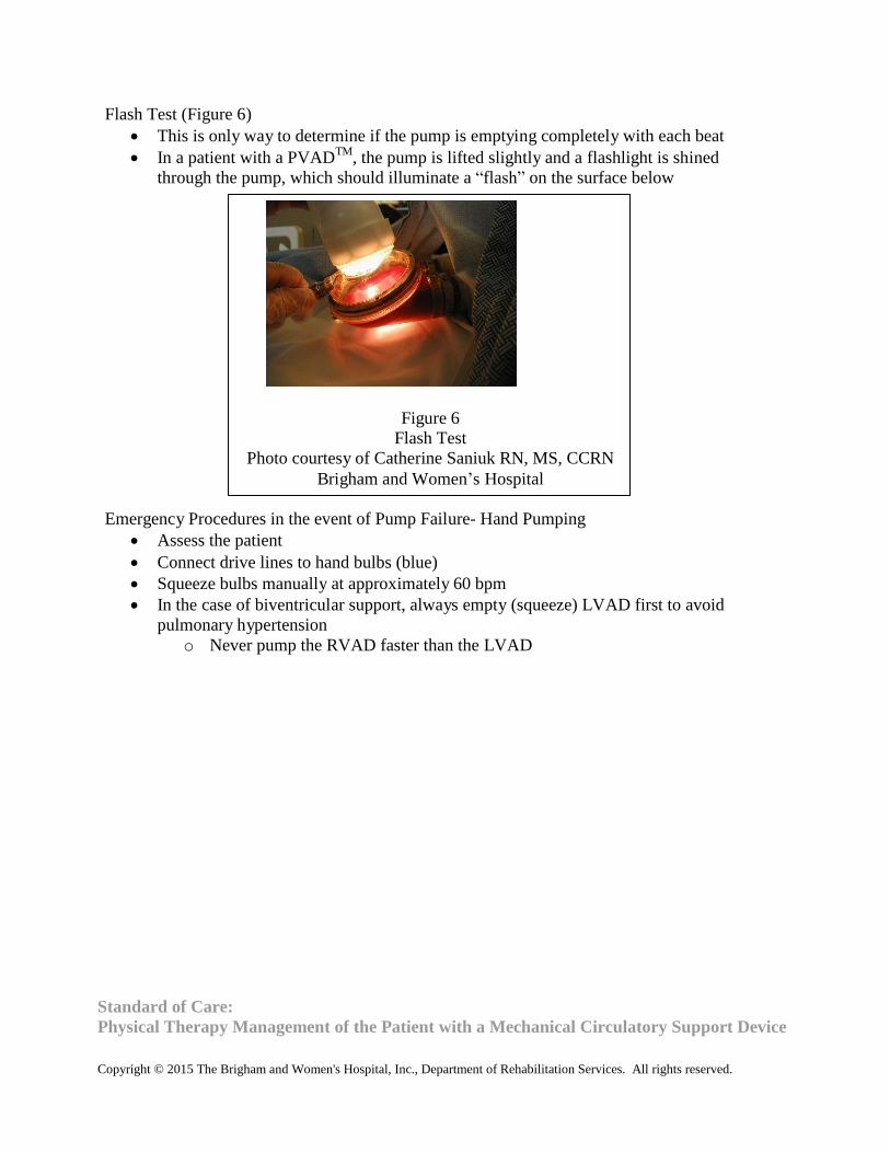
Flash Test (Figure 6)
This is only way to determine if the pump is emptying completely with each beat
In a patient with a PVADTM
, the pump is lifted slightly and a flashlight is shined
through the pump, which should illuminate a “flash” on the surface below
Figure 6
Flash Test
Photo courtesy of Catherine Saniuk RN, MS, CCRN
Brigham and Women’s Hospital Emergency Procedures in the event of Pump Failure- Hand Pumping
Assess the patient
Connect drive lines to hand bulbs (blue)
Squeeze bulbs manually at approximately 60 bpm
In the case of biventricular support, always empty (squeeze) LVAD first to avoid
pulmonary hypertension
o Never pump the RVAD faster than the LVAD

Standard of Care:
Physical Therapy Management of the Patient with a Mechanical Circulatory Support Device
Copyright © 2015 The Brigham and Women's Hospital, Inc., Department of Rehabilitation Services. All rights reserved.
Binder (Figure 7)
Created and fit by OT as soon as medically stable
Wedges provided to keep warm pump off patient’s skin, avoid kinking of drive lines
Anticoagulation
Heparin dosage with goal to maintain PTT 75-80
Warfarin dosage with goal to maintain INR 2.5-3.5
May need Plavix if platelet count greater than 300,000
Rehab Considerations:
When leaving the room with the TLC II®
, the patient should carry an extra battery, one or
two hand pumps for uni- or bi-ventricular support respectively and a TLC-II®
AC adapter
A balance assessment should be completed prior to initiation of ambulation pushing the
portable TLC II®
driver due to the unstable nature of the TLC II®
driver
The patient should be instructed on how to monitor VAD rates and flows during activity
Figure 7
Thoratec® PVAD
TM Binder with Wedges
Photo courtesy of Catherine Saniuk RN, MS, CCRN
Brigham and Women’s Hospital

Standard of Care:
Physical Therapy Management of the Patient with a Mechanical Circulatory Support Device
Copyright © 2015 The Brigham and Women's Hospital, Inc., Department of Rehabilitation Services. All rights reserved.
BRIGHAM AND WOMEN’S HOSPITAL Department of Rehabilitation Services
Physical Therapy
Standard of Care: Mechanical Circulatory Support Device
Appendix B
HeartMate II® Left Ventricular Assistive Device (LVAD)
Figure 1
HeartMate II®
LVAD
HMII LVAS Controller (Pictured Left) HMII LVAD
Pocket Controller (Pictured Right) Reprinted with
permission from Thoratec Corporation
Overview
FDA approved for bridge to transplant or destination therapy
Goal is for discharge home
Most patients have BSA >1.5m2
but the possibility for implantation in patients with BSA
<1.5m2
can be made on a case-by-case basis

Standard of Care:
Physical Therapy Management of the Patient with a Mechanical Circulatory Support Device
Copyright © 2015 The Brigham and Women's Hospital, Inc., Department of Rehabilitation Services. All rights reserved.
The Pump (Figure 2)
Valveless
Preload and afterload sensitive
Follows native pulse
Pump output varies over the cardiac cycle
The pump weighs about 10 ounces
Flexible inflow cannula inserted in the left ventricular apex
Outflow graft connects to aorta via flexible “bend relief” tubing
Inflow and outflow cannulae have textured, thrombo-resistant surfaces
Outflow Cannula
Inflow Cannula
Bend Relief Flex Section
Percutaneous Drive Line
Blood Pump
Figure 2
The HeartMate II®
Pump
Reprinted with permission from Thoratec Corporation
The Rotor
Spins on blood-lubricated bearings
Driven by integrated electric motor which is outside the pump

Standard of Care:
Physical Therapy Management of the Patient with a Mechanical Circulatory Support Device
Copyright © 2015 The Brigham and Women's Hospital, Inc., Department of Rehabilitation Services. All rights reserved.
The Flow Path (Figure 3)
Inflow comes from the left ventricle
Inlet stator is designed to “straighten” the blood before it enters the rotor via three guide
vanes
The rotor propels blood forward and spins it radially
When leaving, the flow is straightened by the outlet stator and pressure is increased
Outflow
Graft
Driveline
Inflow conduit
Rotor
Motor
Outlet Stator
Figure 3
The Flow Path
Reprinted with permission from Thoratec Corporation Flow Principles
Flow is set by the speed of the rotor and the difference between the pressure in the
ventricle and the aorta
o A large difference in pressure gradient will cause low flow o A small difference in pressure gradient will cause high flow
Any contraction of the heart creates a pressure pulse
o Even a severely depressed heart will have some residual contraction
With increased speed the pump offloads the ventricle further
o This will cause more LV contraction
An increase in pressure at the pump inlet (LV) will cause an increase in flow at the outlet
(aorta)
As speed increases, flow will increase
As the pressure gradient increases, flow will decrease

Standard of Care:
Physical Therapy Management of the Patient with a Mechanical Circulatory Support Device
Copyright © 2015 The Brigham and Women's Hospital, Inc., Department of Rehabilitation Services. All rights reserved.
Pulsatility Index (PI)
A measure of the flow pulse through the pump
o Ventricle contraction increases flow across the pump
In normal cardiac physiology, when preload increases in the LV, the force of contraction
increases as described in the Frank-Starling relationship. In heart failure, the myocardium
is overloaded such that the myocardial sarcomeres are overstretched to the point that they
produce a less forceful contraction. As the VAD unloads the ventricle of a heart in
failure, the length tension relationship improves and subsequently the force of contraction
increases and PI increases. As the VAD continues to further unload the ventricle, the
length tension relationship becomes sub-optimal and the force of contraction decreases,
along with the PI of the ventricle (Figure 4)
Pump speed determines the amount of LV unloading and therefore the pulsatility of the
ventricle (Figure 5)
o As speed increases, the PI decreases, indicating more LV unloading o As speed decreases, the PI increases, indicating less LV unloading o Goal PI 4.0
Pump speed
Pressure Difference- mmHg
Flow Rate L/min
Figure 4
Pressure Flow Curve
Reprinted with Permission from Thoratec Corporation

Standard of Care:
Physical Therapy Management of the Patient with a Mechanical Circulatory Support Device
Copyright © 2015 The Brigham and Women's Hospital, Inc., Department of Rehabilitation Services. All rights reserved.
Flo
w, P
I
PPuullssaattiilliittyy IInnddeexx--ssppeeeedd rraammpp
Schematic of events as pump speed is steadily increased
(failing heart)
PI
Pump Flow
LV Unloading
Speed
Rev. 12.0 (3/24/04)
Figure 5
Pulsatility Index-Speed Ramp
Reprinted with Permission from Thoratec Corporation
Suction Event
The system monitors sudden changes in pump flow pulsatility (PI event)
When the PI event (low flow) is detected, the speed of the pump automatically reduces to
the low limit setting to avoid suction
The pump will slowly return to the set speed
May cause ectopic beats
Potential causes:
o Dehydration or pump speed too high

Standard of Care:
Physical Therapy Management of the Patient with a Mechanical Circulatory Support Device
Copyright © 2014 The Brigham and Women's Hospital, Inc., Department of Rehabilitation Services. All rights reserved.
Typical Hemodynamics
Fixed Speed = 6,000-15,000 rotations per minute (rpm)
The flow estimator provides an estimate of pump flow, generally 3.0-6.0 L/min; flow
should not be used to monitor the patient’s status
Power in watts
Pulsatility Index generally 3.0 to 6.0 with goal of 4.0
Blood Pressure will usually not be pulsatile enough to detect with direct auscultation or
with an automatic sphygmomanometer. The clinician must use a manual
sphygmomanometer with a doppler to obtain an estimation of the MAP
MAP should be maintained less than 90
CVP generally should be between 12-15
Generally no O2 Saturation can be detected as blood flow is not pulsatile
Anticoagulation via Warfarin and Aspirin for goal INR 2-3

Standard of Care:
Physical Therapy Management of the Patient with a Mechanical Circulatory Support Device
Copyright © 2014 The Brigham and Women's Hospital, Inc., Department of Rehabilitation Services. All rights reserved.
System Components
Monitor Power
Module
LVAS Original
System Controller
HMII Pocket
Controller
Batteries Battery
Clips
Battery
Charger
Figure 6
System Components
Reprinted with permission from Thoratec Corporation

Standard of Care:
Physical Therapy Management of the Patient with a Mechanical Circulatory Support Device
Copyright © 2014 The Brigham and Women's Hospital, Inc., Department of Rehabilitation Services. All rights reserved.
System Controller
Controls pump speed and power
Monitors and interprets data and responds to system performance
Hazard and advisory alarms
Fully redundant back-up system
Automatic event recording
Has a percutaneous lead connection which should be inserted all the way into the
controller
Latch guard should be in place to protect against accidental disconnect of percutaneous
cable from system controller (pump would stop)
Two Models
o Pocket Controller User interface LED display that can show VAD pump settings (speed,
flow, PI, Power and charge status of backup battery)
Symbols for battery indicator, pump running, status, cable disconnect
Buttons for controlling display, silencing alarms and displaying battery
power gauge
Internal 11 volt lithium-ion backup battery that can provide at least 15
minutes of backup power to the LVAD if external power fails
o LVAS System Controller (Original Controller) Buttons for controller self-test and silencing alarms Icons to indicate battery power gauge, controller power, controller battery,
red heart symbol, battery power source
System controller alarm battery provides limited power to the audible
alarms in situations where external power has been disrupted. DOES NOT
provide backup power to the controller or pump
Power Module (PM)
Provides AC power to the LVAD when connected by a 20' power-based unit (PBU) cable
Color coded connections
o White connection- distributes VAD information to the PBU and display monitor o Black connection- only a source of power, no information communicated
Indicates battery charge status, system malfunction, battery hazard via icons
Interfaces with the display module

Standard of Care:
Physical Therapy Management of the Patient with a Mechanical Circulatory Support Device
Copyright © 2014 The Brigham and Women's Hospital, Inc., Department of Rehabilitation Services. All rights reserved.
Display Monitor
Touch screen interface to allow the user to view and change settings
o Clinical screen displays real-time mode, speed, flow, power and PI o Setting screen allows adjustment of pump parameters o Alarms screen shows history of alarms and alarm settings o Save data screen allows to change data recording parameters o History screen shows history of VAD settings and alarms o Admin screen allows for changing date, time, language, etc.
The patient should be on the PBU any time they are sleeping
Provides 30 minutes of back-up power in the event of power failure
Batteries
Two 14 volt lithium-ion batteries with approximately 8-12 hours of power (as a pair)
Battery clips are required to connect to the system controller or pocket controller
Battery Status On the Battery (Figure 7)
o 5 green lights = 80-100% power remains o 4 green lights = 60-80% power remains o 3 green lights = 40-60% power remains o 2 green lights = 20-40% power remains o 1 green light (steady) = 10-20% power remains o 1 green light (blinking) = <10% power remains (replace batteries one at a time) o No green lights = battery is in sleep mode due to being in storage for a long
period of time. Charge battery immediately
Figure 7
Checking Battery Status Reprinted with
permission from Thoratec Corporation

Standard of Care:
Physical Therapy Management of the Patient with a Mechanical Circulatory Support Device
Copyright © 2014 The Brigham and Women's Hospital, Inc., Department of Rehabilitation Services. All rights reserved.
Battery Status on the Controller
o 4 green lights = 75-100% power remains o 3 green lights = 50-75% power remains o 2 green lights = 25-50% power remains o 1 green light = less than 25% power remains
Battery Alarms
o Less than 15 minutes of power remains, beeps once every 4 seconds o Less than 5 minutes of power remains, continuous tone, defaults to power saver
mode and set speed of 8000 RPMs
Changing from PBU to Battery Power
1. Ensure that the connections between the LVAD driveline and the controller are intact
2. Connect the batteries to the right and left battery clips until the battery clicks into place
(align arrows)
3. Disconnect white controller cable from power based unit and connect to battery and clip
(See Figures 8 and 9)
4. Ensure connections are “hand tight”
5. Disconnect black controller cable from power based unit and connect to battery and clip
6. Ensure connections are “hand tight”
7. Never disconnect both cables at the same time. The pump will STOP!
8. Repeat procedure when returning to power based unit
Figure 9
HeartMate II®
White Controller
Cable Connected to Battery Clip
Reprinted with permission from
Thoratec Corporation
Figure 8
HeartMate II®
White Controller
Cable Disconnected
Photo courtesy of Catherine Saniuk
RN, MS, CCRN
Brigham and Women’s Hospital

Standard of Care:
Physical Therapy Management of the Patient with a Mechanical Circulatory Support Device
Copyright © 2014 The Brigham and Women's Hospital, Inc., Department of Rehabilitation Services. All rights reserved.
Alarms on the controller
Red Heart Alarm (steady audio tone)
o Low flow o Pump has stopped working or is not working properly o Power disconnected from original system controller or pocket controller
Red Battery (steady audio tone)
o Less than 5 minutes of battery power o Low voltage
Controller not getting enough power
Yellow Battery/Yellow Diamond (1 beep every 4 seconds)
o Less than 15 minutes of battery power remain o Low voltage o System controller not getting enough power from PBU
Yellow Controller Cell (1 beep every 4 seconds)
o Battery that powers the system controller audible alarm is depleted
Rapidly Flashing Green Power Symbol (1 beep every second)
o One of the power leads is damaged or disconnected Special Situations
In the case of backflow through the device, PT would note low flow or low speed alarm,
likely due to dilated ventricle
In the case of ventricular recovery, an increase in PI would be noted and, on ECHO, the
aortic valve would open with every beat
During exercise the PT should note an increase in PI due to increased venous return and
increased ventricular contractility
A rapid increase in power may be indicative of a clot in the system
Emergency Procedures in the Event of Pump Failure- Changing the controller
Have the patient sit or lie down
Attach 2 backup batteries to backup controller
Unlock drive line sites on both controllers
Disconnect drive line from non-working controller
Insert the drive line into the backup controller
Daily Routines
System self-test every morning
Exit site wound care completed daily by nursing
Custom abdominal binder or binder provided by the Occupational Therapist is worn at all
times
PT and OT programs
Nutrition
Discharge teaching with Nurse Practitioners

Standard of Care:
Physical Therapy Management of the Patient with a Mechanical Circulatory Support Device
Copyright © 2014 The Brigham and Women's Hospital, Inc., Department of Rehabilitation Services. All rights reserved.
Ambulation Checklist
The patient carries a travel bag with emergency equipment (any time the patient leaves
their hospital room) (Figure 10)
o Spare controller o Spare controller battery (original system controller only) o (2) Spare batteries and (2) spare battery clips
Fresh batteries are inserted prior to ambulation and the battery fuel gauge should be
checked periodically during ambulation, on the controller
Figure 10
Patient travel bag closed (left) and open with spare batteries (right)
Reprinted with permission from Thoratec Corporation

Standard of Care:
Physical Therapy Management of the Patient with a Mechanical Circulatory Support Device
Copyright © 2014 The Brigham and Women's Hospital, Inc., Department of Rehabilitation Services. All rights reserved.
BRIGHAM AND WOMEN’S HOSPITAL Department of Rehabilitation Services
Physical Therapy
Standard of Care: Mechanical Circulatory Support Device
Appendix C
2nd
Generation CentriMag®
Figure 1
CentriMag® System Components- Pump, Display and Console Tower with Mag monitor
and
Console and Motor
Reprinted with permission from Thoratec Corporation
Overview
Extracorporeal short term blood pump
Centrifugal pump
Magnetically levitated impeller

Standard of Care:
Physical Therapy Management of the Patient with a Mechanical Circulatory Support Device
Copyright © 2014 The Brigham and Women's Hospital, Inc., Department of Rehabilitation Services. All rights reserved.
System Components
Pump
o Polycarbonate blood pump with impeller spinning in the “contact-free” chamber
Motor
o Applies both levitational and rotational magnetic force (bearingless) to drive the
impeller inside the blood pump
Console
o Primary console used at the bedside daily o Backup console available to provide temporary life support should the primary
console malfunction, this console does not have flow or pressure sensing capabilities, and the patient should be returned to a primary console as soon as
possible.
o Has digital read out of speed (RPM), flow (Liters per minute [L/min]), alarms and
pressure
o Buttons to view and adjust pump speed and alarms
Mag Monitor
o Displays flow and RPM o Ability to control flow, RPM and auxiliary settings o Stopwatches o Multicolor display that shows VAD settings and alarms
Flow Probe (Figure 2)
o Ultrasonic flow probe connected to the outflow cannula o Can detect flows from 0.9 to 9.9 L/min o Clip on design o Does not need calibrating o Repositioned once per shift to avoid memory kink on the tubing o Can detect retrograde flow, displayed as “---” instead of L/min on console
Figure 2
Ultrasonic Flow Probe
Reprinted with permission from Thoratec
Corporation

Standard of Care:
Physical Therapy Management of the Patient with a Mechanical Circulatory Support Device
Copyright © 2014 The Brigham and Women's Hospital, Inc., Department of Rehabilitation Services. All rights reserved.
Battery Life
Primary Console has a 2-3 hour rechargeable battery, alerts when “ON BATTERY” and
battery gauge indicates level of battery charge
Backup Console is not rechargeable
Clot Check
Performed by nursing every 4 hours by shining a flashlight on the pump, looking for clot
(white specs or streaks) especially at the inflow cannula connection to the pump
Normal Ranges
Pump Speed
o Goal is for RPMs to maintain adequate blood flow without causing excessive emptying of the ventricle leading to “chugging”
o If RPMs are increased, flow should also increase o Generally 2,500-3,500 RPMs
Flow
o Generally 3.0-6.0 LPM, but capable of 10L/min o Usually non-pulsatile o When it is pulsatile, trend pulse pressure (goal 10-15 mmHg)
MAP
o Trended in the ICU via arterial line o Goals is for MAP less than 90
Pump is preload dependent therefore goal is for CVP 10-15
Alarms
“SYSTEM FAULT” Blood pump will stop, an audible alarm will sound that cannot be
muted. Switch to the backup console, motor and flow probe
“MOTOR STOPPED” Blood pump will stop, audible alarm will sound that can be muted
for 60 seconds. Switch to the backup console, motor and flow probe
“BATTERY MODULE FAIL” The console battery will not function. An audible alarm
will sound. Switch to the backup console, motor and flow probe
“BATTERY BELOW MINIMUM” The blood pump will stop shortly. Plug into AC power.
If no AC power available, switch to the backup console, motor and flow probe
“FLOW PROBE DISCONNECTED” Check the flow probe connection on back of console
“SYSTEM ALERT” Press the alarm acknowledge button, if the message does not
disappear, switch to the backup console, motor and flow probe
“FLOW BELOW MINIMUM” Low flow. Check for physiologic cause or circuit
obstruction.
“BATTERY MAINTENANCE REQUIRED” Do not use the console
“LOW BATTERY” Plug the console into AC power. If no AC power is available, switch
to the backup console, motor and flow probe
“ON BATTERY” Verify that the user wants to use battery power, monitor battery charge
status

Standard of Care:
Physical Therapy Management of the Patient with a Mechanical Circulatory Support Device
Copyright © 2014 The Brigham and Women's Hospital, Inc., Department of Rehabilitation Services. All rights reserved.
Anticoagulation
Heparin is started after surgery
Goal PTT 60-80
“Chugging”
Inflow cannula to the pump will begin to sway or move violently
Minimum flow alarm will sound indicating that the pump is likely experiencing
inadequate filling
RN should decrease RPMs in 100 RPM increments until chugging ceases
Team will assess volume status to determine if the patient is dehydrated, has RV failure,
cardiac tamponade, etc.
o “---” on the L/min screen indicates retrograde flow of >40 mL/min
If occurs during mobility with PT, the VAD team should be notified

Standard of Care:
Physical Therapy Management of the Patient with a Mechanical Circulatory Support Device
Copyright © 2014 The Brigham and Women's Hospital, Inc., Department of Rehabilitation Services. All rights reserved.
BRIGHAM AND WOMEN’S HOSPITAL Department of Rehabilitation Services
Physical Therapy
Standard of Care: Mechanical Circulatory Support Device
Appendix D
Cardiac Assist TandemHeart®
Figure 1
Cardiac Assist TandemHeart®
Photo courtesy of Catherine Saniuk RN, MS, CCRN
Brigham and Women’s Hospital
Overview and Indications for Use
Extracorporeal temporary centrifugal ventricular assist device
Provides rapid ventricular off-loading and increased systemic perfusion
Can provide at least 4 liters per minute of flow at 7500 RPMs
Can be placed percutaneously in the femoral vein and advanced to the right atria in the
catheterization lab to provide right ventricular support in patients with a mechanical left
ventricular assistive device in place
Centrally cannulated device can be surgically secured in the operating room to make
mobility possible
Contraindications for Use
Severe peripheral vascular disease

Standard of Care:
Physical Therapy Management of the Patient with a Mechanical Circulatory Support Device
Copyright © 2014 The Brigham and Women's Hospital, Inc., Department of Rehabilitation Services. All rights reserved.
System Components
Polycarbonate pump with impeller spinning in the “contact-free” chamber
Motor which applies both levitational and rotational magnetic force (bearing-less)
System Controller
o Contains an infusion system and 2 separate controllers (primary and backup) o Contains a primary and a backup controller o Switchover from the primary to the backup controller occurs automatically and
without any alert
o Controller is kept plugged in at all times, except during transport or mobility Flow Probe (Figure 2)
Ultrasonic flow probe placed on the outflow cannula
Can detect flows from 0.9 to 9.9 L/min
Clip on design
Does not need calibrating
Repositioned once per shift to avoid memory kink on the tubing
Can detect retrograde flow of >40 mL/min, displayed as “---” instead of L/min on
console
Figure 2
Ultrasonic Flow Probe
Photo courtesy of Catherine Saniuk RN, MS, CCRN
Brigham and Women’s Hospital

Standard of Care:
Physical Therapy Management of the Patient with a Mechanical Circulatory Support Device
Copyright © 2014 The Brigham and Women's Hospital, Inc., Department of Rehabilitation Services. All rights reserved.
The Pump and Cannula (Figures 3 and 4)
Inflow cannula transports blood from the patient into the center of the pump
Outflow cannula transports blood out from the side of the pump to the patient
Upper Housing Chamber: blood flows into the center of the upper housing chamber via
the inflow cannula and is rotated by the impeller at a set speed before being sent back
into the patient’s circulation via the outflow cannula
Lower Housing Chamber: includes the motor and the infusate solution, providing cooling
and a local anti-coagulation effect
Figure 3
Outflow
Inflow
Figure 4
Lower
housing
Upper
Housing
Infusate System
Provides 10 mL/hour IV solution (normal saline, heparin or bivalruidin solution)
Infused directly into the pump under pressure
Goal is to cool and lubricate the rotor
Pressure should be between 100 and 600 mmHg
Battery Life
System Controller has a 60 minute rechargeable battery, and alerts when “ON
BATTERY”
The battery gauge indicates level of battery charge
The battery requires 4 hours to recharge
Clot Check
Performed by nursing every 4 hours, by looking for clot (white specs or streaks)
especially at the inflow cannula connection to the pump
Photos courtesy of Catherine Saniuk RN, MS, CCRN
Brigham and Women’s Hospital

Standard of Care:
Physical Therapy Management of the Patient with a Mechanical Circulatory Support Device
Copyright © 2014 The Brigham and Women's Hospital, Inc., Department of Rehabilitation Services. All rights reserved.
Typical Hemodynamics
Pump Speed
o Goal is for RPMs to maintain adequate blood flow without causing excessive emptying of the ventricle leading to “chugging”
o If RPMs are increased, flow should also increase o The pump is capable of generating speeds of 3,500-7,500 RPMs
Flow
o Detected via the flow probe and is generally a “real” flow o Generally 3.0-6.0 L/min
“Chugging”
Inflow cannula to the pump will begin to sway or move violently
Minimum flow alarm will alarm, the pump is likely experiencing inadequate filling
RN should decrease RPMs in 100 rpm increments until chugging ceases
The VAD team should be notified
The team will assess volume status, potential causes include
o Dehydration o Right ventricular failure o Cardiac tamponade
Anticoagulation
o Heparin begun after surgery o Goal PTT 60-80
Considerations
The pumps should be kept visible at all times and should never be covered with bed linen
The patient should logroll for all bed mobility and care
Daily dressing changes are conducted by the nursing staff per VAD guidelines
The pump should be secured with a binder or holster at all times
The pump should not be touching the skin at any time due to the risk of burns
Products with acetone (e.g. a permanent marker or nail polish remover) should not ever
be used near the site due to the risk of cannula degradation.

Standard of Care:
Physical Therapy Management of the Patient with a Mechanical Circulatory Support Device
Copyright © 2014 The Brigham and Women's Hospital, Inc., Department of Rehabilitation Services. All rights reserved.
BRIGHAM AND WOMEN’S HOSPITAL Department of Rehabilitation Services
Physical Therapy
Standard of Care: Mechanical Circulatory Support Device
Appendix E
HeartWare®
HVAD
Overview
Indicated for patients at risk of death with end-stage left ventricular heart failure
Approved as a bridge to cardiac transplant
Displaces 50cc blood volume in the left ventricle
For more detailed information, refer to heartware.com → Clinicians → Instructions for
Use
Flow Principles
Continuous flow
o Blood travels from the left ventricle, into the HVAD®
via the inflow cannula, then
exits via the outflow cannula and enters the ascending aorta where blood can be
circulated throughout the body before returning to the right ventricle.
Constant speed
Can deliver up to 10L/min of flow
Output is dependent on speed of impeller and pressure differential across the pump
Works harder during systole than diastole
o Occurs due to volume of blood in the pump o Less chance of suction event or RV dysfunction
Preload dependent and afterload sensitive
o Preload is volume of blood returning to the right ventricle, left ventricle or LVAS o Afterload is the resistance the RV, LV or LVAD has to pump against to empty
Can be affected by volume
Figure 1
HeartWare® Ventricular Assistive System (HVAD
®)
Reprinted with permission from HeartWare® Inc

Standard of Care:
Physical Therapy Management of the Patient with a Mechanical Circulatory Support Device
Copyright © 2014 The Brigham and Women's Hospital, Inc., Department of Rehabilitation Services. All rights reserved.
Typical Hemodynamics
Mean arterial pressure (MAP)
o Must maintain MAP <85 mmgH o Can approximate via Doppler blood pressure monitoring
Acceptable range for Doppler BP is 65-90 mmgH
Anticoagulation
o Long term anticoagulation via Warfarin and Aspirin Target INR 2.0-3.0
Speed (RPM)
o Full range is 1800 to 4000 RPM o Typical range in patients is 2400 to 3200 RPM
Power (Watts)
o Full range is 2.5 to 8.5 Watts
Flow (L/min)
o Calculated by a combination of hematocrit and pump speed In the very acute phase, hematocrit must be adjusted daily
o Full range is -2 to 10 L/min -2 L/min is an invalid but can indicate incorrect hematocrit Flows of 10 L/min and greater can be indicative of a clot or other material
in the device or an incorrect hematocrit
o At flows > 6.5, it is critical to monitor MAP
Figure 2
Monitor Display of HVAD®
Pump Settings
Reprinted with permission from HeartWare® Inc.

Standard of Care:
Physical Therapy Management of the Patient with a Mechanical Circulatory Support Device
Copyright © 2014 The Brigham and Women's Hospital, Inc., Department of Rehabilitation Services. All rights reserved.
1
.
Flow Pulsatility (for graphic representation, refer to “Instructions for Use” on
heartware.com)
o The difference between the maximum (peak) and minimum (trough)
of the flow waveform
Should be >2 L/min Ideal range is between 2-4 L/min
o Waveform trough should be >2 L/min
Suction Event (for graphic representation, refer to “Instructions for Use” on heartware.com)
Occurs during ventricular collapse or inflow occlusion
o Ventricular collapse occurs if VAD speed is too high and it attempts
to pump more blood from the left ventricle than is available, thus reducing the ventricular volume
Can be due to hypovolemia due to acute bleeding, right
heart failure, arrhythmia, or pulmonary embolus
o Inflow obstruction is typically temporary and can occur due
to surgical positioning, patient positioning, or during a
valsalva maneuver Typical System Components
Figure 3
HVAD®
System Components
1. HVAD®
Pump 2. Monitor
3.Controller 4. Batteries 5. Driveline
Reprinted with permission from HeartWare®
Inc.
2
3 4
5
4

Standard of Care:
Physical Therapy Management of the Patient with a Mechanical Circulatory Support Device
Copyright © 2014 The Brigham and Women's Hospital, Inc., Department of Rehabilitation Services. All rights reserved.
The HVAD® Pump
Figure 4
HVAD®
Pump
Reprinted with permission from HeartWare®
Inc.
Centrifugal flow pump
Weighs 160 grams
Seated inside the pericardium (Figure 4)
Valveless Pump
Inflow cannula that is attached directly to the left ventricle (Figure 5)
Levitating impeller inside housing
o Barrier between impeller and housing o Hydrodynamics make the propeller levitate so there is virtually no friction
Figure 5
HVAD® in-situ with outflow cannula and driveline
Reprinted with permission from HeartWare® Inc

Standard of Care:
Physical Therapy Management of the Patient with a Mechanical Circulatory Support Device
Copyright © 2014 The Brigham and Women's Hospital, Inc., Department of Rehabilitation Services. All rights reserved.
Powered by two separate motors work independently and are connected with pacing
wires
o If one fails, the other can take over
Outflow cannula travels along the right ventricle and is grafted to the ascending aorta
Connected to the external controller via a percutaneous driveline
o Similar to wires used in pacemakers
The Controller (Figure 6)
Controls and manages VAD operation
Contains an internal battery to run an audible “No Power” alarm
Has connections for the driveline, 2 power connection sources and a data connection port
that sends signals to the monitor for downloading pump information and adjusting pump
settings
Has an LCD display that shows information on pump operation, battery indicators for
both power sources, alarm indicator, alarm mute button, scroll button and AC/DC
indicator
Figure 6
HVAD®
Controller and LCD Display
Reprinted with permission from HeartWare®
Inc.

Standard of Care:
Physical Therapy Management of the Patient with a Mechanical Circulatory Support
Device
Copyright © 2014 The Brigham and Women's Hospital, Inc., Department of Rehabilitation Services. All rights reserved.
The Touch Screen Monitor (Figure 7)
Displays and controls the HeartWare®
system and pump
o Displays pump information o Allows for adjustment of pump parameters o Monitors and reports system errors and alarms
Monitor Screen Layout
o Top of Screen- Alarm messages, status messages, alarm silence and
logout buttons
o Bottom of Screen- Downloading data icon, patient identification, time,
postoperative day, controller power supply status, controller power supply
source
o Left Side of Screen- Displays pump information (Speed, Flow, Power) o Middle of Screen- Dependent on which of the five information screens is
running
Five icons on the monitor allow for access of different types of information
and adjustments o Clinical (Home) Screen (Figure 7)
Shows real-time power and HVAD®
pump flow waveform
o System Screen
Password protected
Allows for access to: speed/control adjustments, patient/VAD data, and
alarm settings
o Alarm Screen: including alarm log/history and troubleshooting of alarms
o Trend Screen: Flow/Speed and Flow/Power trends
o Monitor Shut Down
Figure 7
HVAD® Monitor Clinical (Home) Screen
Reprinted with permission from HeartWare® Inc

Standard of Care:
Physical Therapy Management of the Patient with a Mechanical Circulatory Support
Device
Copyright © 2014 The Brigham and Women's Hospital, Inc., Department of Rehabilitation Services. All rights reserved.
Power Sources
Utilizes AC, DC, or battery power
Utilizes one power source at a time
o Completely uses one battery before using the other
AC adapter (for wall outlet)
o Green light on adapter will illuminate when plugged into wall outlet and receiving
power
o Must use battery as second power source
o The HVAD®
will always use the AC power source as the primary source when
plugged in
DC adapter (for car use)
o Green light on adapter will illuminate when plugged into car outlet and receiving
power
o Must use battery as second power source
o The HVAD®
will always use the AC/DC power source as the primary source
when plugged in
o May not fit in some vehicles
HeartWare®
Batteries (See Figure 3 above) o Lithium ion cell batteries o Weigh ~1 lb each o Provide 4-6 hours of power when fully charged
Exact amount of time dependent on controller and pump operating power consumption
Number of battery charge/discharge cycles
Lifetime of battery expected to be >500 cycles
Must replace battery when lasting <2 hours of charge
o Battery power indicator By pushing button on the battery
4 green lights- 75-100%
3 green lights- 50-74%
2 green lights- 25-49%
1 green light- <24% (will switch to other battery automatically)
On the controller display
4 green lights- 75-100%
3 green lights- 50-74%
2 yellow lights- 25-49%
1 red light- <25%
Only change the battery when the controller instructs to do so

Standard of Care:
Physical Therapy Management of the Patient with a Mechanical Circulatory Support Device
Copyright © 2014 The Brigham and Women's Hospital, Inc., Department of Rehabilitation Services. All rights reserved.
o Battery Charger Can charge up to 4 batteries at a time Takes 5 hours to completely charge a depleted battery
Indicator lights show battery charger power, status light and ready light
Ready Light
Green- Battery is fully charged and ready for use
No color- See status light for where battery is in charging status
Status Light
Yellow- Battery being charged and not ready for use
Flashing Yellow- Battery not charging. Check battery connections.
If connection is intact, switch to another battery slot. If problem
persists contact HeartWare®
for a new battery
Red- Battery too cold or too hot; waiting to charge
Flashing Red- Defective battery. DO NOT use. Return battery to
HeartWare®
Changing from AC power to Battery Power
Locate where the AC power supply connects to the controller (connector has a sleeve that
rotates)
Gently turn the connector sleeve counterclockwise (in the direction of the release arrow)
until it stops moving
Pull straight back to remove the cable it from the controller and place aside
Locate the battery cable and grasp behind the connector sleeve
Line up the white arrow on the connector with the white dot at controller insertion site
Gently push (do not twist) the cable into the controller until it locks (you will hear a
click)
Confirm the cable is locked by gently pulling the cable
Alarms
High (Critical) Priority Alarms
o Blank Display LCD Display Line 1 (Alarm Display)- none LCD Display Line 2 (Action)- none
Alarm Tone- continuous loud, unable to mute
Alarm Symbol- none
Potential Actions- Connect to new power source, replace controller
o VAD Stopped LCD Display Line 1 (Alarm Display)- ‘VAD Stopped’ LCD Display Line 2 (Action)- ‘Connect Driveline’ or ‘Change Controller’
Alarm Tone- Loud two-toned, unable to mute
Alarm Symbol- Flashing Red Triangle
Potential Actions- Reconnect driveline or exchange controller

Standard of Care:
Physical Therapy Management of the Patient with a Mechanical Circulatory Support
Device
Copyright © 2014 The Brigham and Women's Hospital, Inc., Department of Rehabilitation Services. All rights reserved.
o Controller Failed, Critical Battery LCD Display Line 1 (Alarm Display)- ‘Controller Failed’ or ‘Critical
Battery 1’ or ‘Critical Battery 2’
LCD Display Line 2 (Action)- ‘Change Controller’ or ‘Replace Battery 1’
or ‘Replace Battery 2’
Alarm Tone- Loud two-toned, unable to mute
Alarm Symbol- Flashing Red Triangle
Potential Actions- Exchange controller, Replace critical battery with fully
charged battery or AC/DC adapter, change controller if new power
sources do not correct alarm
Medium Priority Alarms
o Alarm Tone- Intermittent beep (gradual increase in alarm volume over time if not
muted), able to mute alarm for 5 minutes or 1 hour, electrical fault and controller fault audio alarms can be permanently disabled, press the scroll button on the controller to clear resolved medium alarm messages
o Alarm Symbol- Flashing Yellow Triangle o Controller Fault
LCD Display Line 1 (Alarm Display)- ‘Controller Fault’ LCD Display Line 2 (Action)- ‘Call’ or ‘Call: ALARMS OFF’
Potential Causes- Controller component malfunction but pump still
working
o High Watt LCD Display Line 1 (Alarm Display)- ‘High Watt’ LCD Display Line 2 (Action)- ‘Call’
Potential Causes- Power (watts) have exceeded high power threshold, high
RPM, high flow, LVAD electrical fault
o Electrical Fault LCD Display Line 1 (Alarm Display)- ‘Electrical Fault’ LCD Display Line 2 (Action)- ‘Call’
Potential Causes- fault in pump-to-controller electrical connections, partial
driveline fracture, connector malfunction, controller component failure,
VAD failure, controller dropped
o Low Flow LCD Display Line 1 (Alarm Display)- ‘Low Flow’ LCD Display Line 2 (Action)- ‘Call’
Potential Causes- average flow below low flow alarm threshold, suction,
RPM too high or too low, poor VAD filling, high blood pressure, outflow
graft kink
o Suction LCD Display Line 1 (Alarm Display)- ‘Suction’ LCD Display Line 2 (Action)- ‘Call’
Potential Causes- RPM too high, poor VAD filling, thrombus

Standard of Care:
Physical Therapy Management of the Patient with a Mechanical Circulatory Support Device
Copyright © 2014 The Brigham and Women's Hospital, Inc., Department of Rehabilitation Services. All rights reserved.
Low Priority Alarms
o Alarm Tone- Intermittent beep (gradual increase in alarm volume over time if
not muted), able to mute alarm for 5 minutes
o Alarm Symbol- Solid Yellow Triangle o Low Battery, Power Disconnect
LCD Display Line 1 (Alarm Display) - ‘Low Battery 1’, ‘Low Battery 2’ or ‘Power Disconnect’
LCD Display Line 2 (Action) - ‘Replace Battery 1’, ‘Replace Batter 2’,
‘Reconnect Power 1’, or ‘Reconnect Power 2’
Potential Causes - Battery power is low, power source is disconnected
or malfunctioning
Special Equipment
Patients will be fit with an abdominal binder
o In some cases, this will be custom made by an Occupational Therapist
Patients will receive a patient pack, waist belt or shoulder bag with pockets for the
controller and batteries
Patients will receive a shower bag that is water resistant
o Occupational Therapist will review showering procedures
Patients will receive a travel bag for backup equipment
Emergency Procedures
Changing the controller
o Have patient sit or lie down o Place new controller in reach o Connect new controller to power supply
A power disconnect alarm will activate if a second source is not connected to the new controller within 20 seconds of controller power up
A VAD stopped alarm will activate if the pump driveline is not
connected to the new controller within 10 seconds (will resolve once
driveline is connected)
o Pull the white cover from the primary controller to reveal the silver connector
of the driveline
o Disconnect the driveline from the primary controller by pulling the silver connector away from the controller
o Connect the driveline to the new controller by aligning the red dot on the
driveline connector with the red dot on the controller and pushing together
An audible click will indicate a secure connection
o Remove the red alarm adapter from the primary controller and remove the
power supply
o Slide the white cover over the driveline connection site on the new driver

Standard of Care:
Physical Therapy Management of the Patient with a Mechanical Circulatory Support Device
Copyright © 2014 The Brigham and Women's Hospital, Inc., Department of Rehabilitation Services. All rights reserved.
Special PT Considerations
Travelling out of the patient’s room
o Must bring travel bag Contains backup controller, two fully-charged spare batteries, AC/DC
power cord
Hemodynamic monitoring
o Blood pressure- via Doppler o Flow pulsatility- when monitor is in use during the immediate post-operative
phase When patient’s become more stable, monitor will not be readily available
during PT session
Must closely monitor patient’s symptoms and blood pressure to ensure
hemodynamic and pump stability

Standard of Care:
Physical Therapy Management of the Patient with a Mechanical Circulatory Support Device
Copyright © 2014 The Brigham and Women's Hospital, Inc., Department of Rehabilitation Services. All rights reserved.
BRIGHAM AND WOMEN’S HOSPITAL Department of Rehabilitation Services
Physical Therapy
Standard of Care: Mechanical Circulatory Support Device
Appendix F
SynCardia temporary Total Artificial Heart (TAH-t)
Figure 1
SynCardia TAH-t
Courtesy: SynCardia Systems, Inc.
Overview
Pulsatile, biventricular pneumatic driven orthotopic device
Replaces both native heart ventricles and heart valves in patients with biventricular heart
failure at risk for imminent death
Weighs 160 grams (~1/3 of a pound)
Occupies 400 cm2
of space
Two Sizes
o 70cc TAH-t currently approved in US and Canada as a bridge to transplant in
eligible patients with BSA of 1.7m3
or greater. This device has been used in
patients with BSA >1.5m3
o 50cc TAH-t currently under development and in clinical trials (awaiting FDA
approval) for patients as a bridge to transplant in both adult and pediatric patients
or a destination therapy in adults with BSA between 1.2m3
and 1.79m3

Standard of Care:
Physical Therapy Management of the Patient with a Mechanical Circulatory Support Device
Copyright © 2014 The Brigham and Women's Hospital, Inc., Department of Rehabilitation Services. All rights reserved.
The Device
Figure 2
The TAH-t Device in two views
Courtesy: SynCardia Systems, Inc.
Artificial ventricles each have a fill volume of 70mL and consist of inner diaphragms
surrounded by a rigid outer polycarbonate casing
Inner polyurethane diaphragms separate blood from air pressure pulses
Has unidirectional inflow and outflow tilting valves
Air pressure pulses controlled by external driver
Large inflow conduit allows for high cardiac output of up to 9.5 L/min
The Pump Cycle (Figure 3)
Blood exits the native right atrium and enters the artificial right ventricle which partially
fills before fully ejecting through a short outflow cannula grafted to the pulmonary artery
to enter the lungs
Blood returns from the lungs into the left atrium, flows into the artificial left ventricle
which partially fills before fully ejecting through an outflow cannula grafted to the aorta
to circulate the body with oxygenated blood.
Figure 3
Graphical representation of cardiac cycle in the TAH-t
Courtesy: SynCardia Systems, Inc.

Standard of Care:
Physical Therapy Management of the Patient with a Mechanical Circulatory Support Device
Copyright © 2014 The Brigham and Women's Hospital, Inc., Department of Rehabilitation Services. All rights reserved.
Typical Hemodynamics
Native heart rate should be 125 15 bpm; device settings allow range of 40 to 150 bpm
Drive pressures
o Left: 180 to 210mmHg needed to overcome native pressure but device settings
allow range of 120 to 280 mmHg
o Right: 60-100mmHg but device settings allow range of 40 to 150 mmHg
Percent systole should be 50% 5% at rest, 60% or less with activity but device settings
allow range of 40 to 60%
Vacuum control
o Right: 0 to -10 mmHg but device settings allow range of 0 to -30 mmHg
o Left: 0 to -13 mmHg but device settings allow range of 0 to -30 mmHg. Left
vacuum typically lower than right.
Companion 2 Driver
Figure 4
Companion 2 Driver shown docked in the hospital cart and by itself
Courtesy: SynCardia Systems, Inc.
Overview
Pneumatic driver delivers pulses through drive lines to push air into the air chambers of
the ventricles to distend the diaphragms in order to eject the blood from the TAH-t
Three modes
o OR mode- Requires password, muted alarms, full menu access, System Check
o ICU mode- Requires password to enter ICU mode from ambulatory mode, double
confirmation required for parameter changes
o Ambulatory mode- No parameter changes permitted, ability to minimize graph
and settings data

Standard of Care:
Physical Therapy Management of the Patient with a Mechanical Circulatory Support Device
Copyright © 2014 The Brigham and Women's Hospital, Inc., Department of Rehabilitation Services. All rights reserved.
Driver can be docked in the hospital cart or caddy
o Hospital cart is larger, more difficult to move
Allows for more parameter changes
o Caddy allows for easier patient mobility
Screen displays: Device rate, Stroke volume, Cardiac output, Drive
pressure, Flow waveforms, Cardiac output trends, Alarms
Display Screen and User Interface
Figure 5
Companion 2 Driver docked in caddy
Courtesy: SynCardia Systems, Inc.
Figure 6
TAH-t User Interface Screen
Courtesy: SynCardia Systems, Inc.

Standard of Care:
Physical Therapy Management of the Patient with a Mechanical Circulatory Support Device
Copyright © 2014 The Brigham and Women's Hospital, Inc., Department of Rehabilitation Services. All rights reserved.
Touchscreen display can be used to monitor and change settings (depending on mode)
Alarms at top of screen via ‘Alarm Bar’
Graphical display of TAH-t function (pressure waveform, flow waveform, cardiac output
waveform)
Real-time numerical values output data (Left/Right cardiac output, Left/Right average
cardiac output, Left/Right fill)
Driver settings (Rate, Percent systole, Left drive pressure, Right drive pressure,
Left/Right vacuum, Average cardiac output)
Displays Air source (external vs. internal)
Power Management displays what power source is being used and how much battery is
remaining along with when the Emergency battery is in use
Figure 7
Battery Power Indicators as shown on display monitor
Courtesy: SynCardia Systems, Inc.
Waveforms
Flow Waveform
o Want to see graph indicative of partial filling of the ventricle demonstrated by
graph line staying above baseline level
Pressure Waveform
o Want to see graph indicative of full ejection from ventricle via “Full Eject Flag”
Full Eject Flag Partial Eject
(No flag)
Figure 8
Graphical representation of full vs. partial ejection
Courtesy: SynCardia Systems, Inc.

Standard of Care:
Physical Therapy Management of the Patient with a Mechanical Circulatory Support Device
Copyright © 2014 The Brigham and Women's Hospital, Inc., Department of Rehabilitation Services. All rights reserved.
Air Source
Utilizes compressed air from internal or external source
External air obtained via yellow air connector to the driver from the hospital wall, ideally
with air pressure between 40-60 PSI
Internal air obtained via internal compressor (no external compressed air tanks)within the
driver
Alarms
High Priority Alarms
o Very Low Left Cardiac Output- Flashing Red Alarm Bar, Flashing red Alarm
Indicator LED, 10 beeps every 2 ½ seconds
o Emergency Battery in Use- Flashing red alarm bar, Flashing red Emergency
Battery Indicator, 10 beeps every 2 ½ seconds
o Low Left Cardiac Output- Red Alarm Bar, Red Alarm Indicator LED, 10 beeps
every 5 seconds
o Low Right Pressure- Red Alarm Bar, Red Alarm Indicator LED, 10 beeps every 5
seconds
Low Priority Alarms
o Very Low External Battery- Flashing Yellow Alarm Bar, Flashing Yellow Alarm
Indicator LED, Flashing Yellow Battery ½ Indicator, 3 beeps every 30 seconds
o Left Fill Volume High- Left Fill Volume Box background is yellow, Flashing
Yellow Alarm Bar, Flashing Yellow Alarm Indicator LED, 3 beeps every 30
seconds
o Low External Battery- Yellow Alarm Bar, Yellow Alarm Indicator LED, Yellow
Battery Indicator, 2 beeps every 3 ½ seconds
o Right Vacuum Incorrect- Yellow Alarm Bar, Yellow Alarm Indicator LED, 2
beeps every 3 ½ seconds
Can View Alarm History via touchscreen interface
Special Considerations for PT
With activity, systolic blood pressure may decrease.
Parameters to know:
o Cardiac output: Decrease activity when CO>8.0 L/min
o Fill Volume: Decrease activity when FV >65mL or high fill alarm sounds
o Blood Pressure: No initiation of therapy if SBP >=130 mmHg, termination of
therapy if SBP >=140 mmHg

Standard of Care:
Physical Therapy Management of the Patient with a Mechanical Circulatory Support Device
Copyright © 2014 The Brigham and Women's Hospital, Inc., Department of Rehabilitation Services. All rights reserved.
Emergency Procedures
In an emergency situation where the current driver malfunctions, it is required to switch
to a backup driver
o Switching to another Companion 2 Driver
Turn on backup driver (takes approximately 10 seconds to begin pumping)
Move driveline from primary driver to backup driver
Depress tab on side of connector to disconnect
Verify adequate battery charge and/or AC power supply connection on
new driver
o Switching to Freedom® Driver
Will need two people, wire cutter and wire ties
Turn on Freedom® Driver, Remove Freedom
® driveline caps, insert
two batteries and connect to AC power
Cut wire ties on Companion driveline
Simultaneously disconnect red and blue cannula from Companion
drivelines
Connect to red and blue Freedom® drivelines
Secure connector release buttons with wire ties
Figure 10
Disconnecting and reconnecting drive line from Companion 2
Driver to Freedom®
Driver
Courtesy: SynCardia Systems, Inc.

Standard of Care:
Physical Therapy Management of the Patient with a Mechanical Circulatory Support Device
Copyright © 2014 The Brigham and Women's Hospital, Inc., Department of Rehabilitation Services. All rights reserved.
Hand Pumping
o Used in emergency situations only when a backup driver is not immediately
available
o Disconnect Driveline from driver
o Connect Driveline to hand pump
o Pump at rate of 110 strokes per minute to provide adequate cardiac output until a
backup driver is available
Figure 11
SynCardia hand pump used in emergency procedure
Courtesy: SynCardia Systems, Inc.

Standard of Care:
Physical Therapy Management of the Patient with a Mechanical Circulatory Support Device
Copyright © 2014 The Brigham and Women's Hospital, Inc., Department of Rehabilitation Services. All rights reserved.
Freedom Portable Driver
Overview
Lightweight and portable (13.5 pounds) and fits in backpack or shoulder bag
6 feet of line from patient to the driver
Patients must be clinically stable (off all IV medications)
o Systolic blood pressure must remain below 140 mmHg
Only adjustable setting is the beat rate
Has air compressor
Can be connected to external AC power source or use battery power
o Batteries insert directly into driver
o Batteries contain approximately 2 hours of power
Figure 12
SynCardia Freedom® Driver connected to the TAH-t
Courtesy: SynCardia Systems, Inc.

61
Has small LCD display (Figure 13)
o Shows single beat rate (BPM), Fill Volume (FV), Cardiac Output (CO), Alarm
indicators that are indicative of LV function
Figure 13
Freedom portable driver with illuminated display and battery indicators
Courtesy: SynCardia Systems, Inc.
Power Source
External- AC or DC power sources from wall or car, respectively
o Cords plug directly into power adapter attached to the Freedom® Driver
Battery power
o Utilizes two batteries at a time
o Provide approximately 2 hours of support according to Driver settings
o Five green lights indicate amount of charge
Each light illuminated represents approximately 20% charge
o Only one battery can be removed at a time
Driver must be plugged into an external power source
Push down on the battery release button at the front of the driver
o When replacing a new battery, must ensure that the battery locks into place
Charging batteries
Figure 14
Batteries charging in dock connected to AC power
Courtesy: SynCardia Systems, Inc.
o Battery charging dock holds up to four batteries at a time
o Charger plugs into an AC power source
o To make sure batteries are charging, depress the battery charge button at the top
of the battery
A blinking light on the battery fuel gauge indicates battery is charging
when battery charge button is depressed
Batteries are done charging when 5 green lights illuminate without
blinking when battery charge button is depressed

62
Alarms
Three Types: Battery Alarm, Temperature Alarm, Fault Alarm
o All will have a visual and audio alarm
Battery Alarm
o Loud Intermittent Tone, Yellow Battery LED flashing
o Indicative of one or both of the batteries having less than 35% charge remaining,
onboard battery is incorrectly installed, one onboard battery is missing
Temperature Alarm
o Loud Intermittent Tone, Red Alarm LED flashing
o Indicative of internal temperature of driver too hot, onboard batteries is too hot
Fault Alarm
o Loud Continuous Tone, Red Alarm LED solid
o Indicative of kinked or disconnected driveling, driver malfunction, low cardiac
output (can be caused by valsalva or elevated SBP)
Emergency Procedures
In an emergency situation where the current driver malfunctions, it is required to switch
to a backup driver
o Switching to backup Freedom® Driver
Requires two people, wire cutters and wire ties
Power on the backup driver
Remove the driveline caps, insert one charged battery, remove
dummy battery and insert second battery, connect the driver to a
wall power outlet
Cut wire ties on Companion driveline
Simultaneously disconnect red and blue cannula from Companion
drivelines
Connect to red and blue Freedom® drivelines
Secure connector release buttons with wire ties
Physical Therapy Considerations
When travelling outside of the patient’s room
o Must bring travel bag with backup Freedom® driver with dummy batter and
fully charged battery inserted, 2 fully charged additional batteries, AC power
adapter

63
Big Blue
Air Source
o Runs on external air
o Will automatically change from air on wall unit to primary tank and then reserve
tank based on highest air pressure system
o For ambulation outside of the room, there is a caddy that holds 4 tanks
For longer excursions, take an extra air tank
o Must always disconnect adapter from wall air unit instead of from Big Blue when
changing oxygen source for travel
o Primary air tank
Has approximately one hour of air
Located on left side of Big Blue
Runs on 4000 PSI
Will alarm when at 1000 PSI
Automatically activates when Big Blue is disconnected from wall air unit
Must always reconnect to wall air unit when returrning from excursion
o Reserve Air Tank
Has approximately one hour of air
Do not want to use unless absolutely necessary
Located on right side of Big Blue
Will alarm at 3000 PSI
Alarm will go off every 3 minutes 30 second until replaced with a
full tank to reset the alarm
3 Panels
o Primary Driver, Secondary Driver, Air System Panel
Air system Panel
Utilizes a graduated alarm system with the most common alarms
being the orange and yellow alarms. Red alarms are most serious
Primary Driver (and secondary driver if in use)
Red and Blue waveforms
o Red line shows right ventricle function
o Blue line shows left ventricle function
o Filling is indicative of diastole
Only want partial filling
Measure of blood flow is equal to air flow
If HR decreases, the time blood is in the ventricle
increases
o Vacuum
Pulls air to decrease resistance in the system
Vacuum increase to <=40 can create atrial suction

64
Works Cited 1. World Health Organization. International statistical classification of diseases and related
health problems 10th revision. http://www.who.int/classifications/apps/icd/icd10online/.
Published 05/04/2006. Updated 2010. Accessed 10/2014, 2014.
2. Lloyd-Jones D, Adams R, Carnethon M, et al. Heart disease and stroke statistics--2009 update:
A report from the american heart association statistics committee and stroke statistics
subcommittee. Circulation. 2009;119(3):e21.
3. Braunwald E. Heart failure. JACC Heart Fail. 2013;1(1):1-20.
4. Shapiro PA, Levin HR, Oz MC. Left ventricular assist devices psychosocial burden and
implications for heart transplant programs. Gen Hosp Psychiatry. 1996;18:30-35.
5. Shoemaker M, J., Caskell A, VandeBunte K, et al. Early ambulation predicts length of stay
and discharge location following left ventricular assist device implantation. Cardiopulm Phys
Ther J. 2014;25(3):75-84.
6. Boehmer JP, Popjes E. Cardiac failure: Mechanical support strategies. Crit Care Med.
2006;34(9):S268.
7. Slepian M. The SynCardia temporary total artificial heart-- evolving clinical role and future
status. US Cardiol. 2011;8(1):39-46.
8. Shah KB, Tang DG, Cooke RH, et al. Implantable mechanical circulatory support:
Demystifying patients with ventricular assist devices and artificial hearts. Clin Cardiol.
2011;34(3):147-152.

65
9. Platis A, Larson DF. CardioWest temporary total artificial heart. Perfusion. 2009;24(5):341-
346.
10. Boldt C, Grill E, Wildner M. ICF core set for patients with cardiopulmonary conditions in the
acute hospital. Disabil Rehabil. 2005;27(7-8):375-380.
11. Boyle AJ, Jorde UP, Sun B, et al. Pre-operative risk factors of bleeding and stroke during left
ventricular assist device support: An analysis of more than 900 HeartMate II outpatients. J Am
Coll Cardiol. 2014;63(9):880-888.
12. Shah MR, Naftel DC, Miller MA, et al. Thrombotic complications increase after
percutaneous Site/Pocket infection in patients with left ventricular assist devices: An
INTERMACS analysis. J Heart Lung Transplant. 2013;32(4):84-85.
13. Monkowski D, Axelrod P, Fekete T, Hollander T, Furukawa S, Samuel R. Infections
associated with ventricular assist devices: Epidemiology and effect on prognosis after
transplantation. Transpl Infect Dis. 2007;9(2):114.
14. Mancini D, Goldsmith R, Levin H, et al. Comparison of exercise performance in patients
with chronic severe heart failure versus left ventricular assist devices. Circulation.
1998;98(12):1178-1183.
15. Oz MC, Argenziano M, Catanese KA, et al. Bridge experience with long-term implantable
left ventricular assist devices are they an alternative to transplantation? Circulation.
1997;95(7):1844-1852.

66
16. Potapov EV, Loforte A, Weng Y, et al. Experience with over 1000 implanted ventricular
assist devices. J Card Surg. 2008;23(3):185-194.
17. Mountis MM, Starling RC. Management of left ventricular assist devices after surgery:
Bridge, destination, and recovery. Curr Opin Cardiol. 2009;24(3):252.
18. Kohli HS, Canada J, Arena R, et al. Exercise blood pressure response during assisted
circulatory support: Comparison of the total artifical heart with a left ventricular assist device
during rehabilitation. J Heart Lung Transplant. 2011;30(11):1207-1213.
19. Nicholson C, Paz JC. Total artificial heart and physical therapy management. Cardiopulm
Phys Ther J. 2010;21(2):13-21.
20. Holman WL, Rayburn BK, McGiffin DC, et al. Infection in ventricular assist devices:
Prevention and treatment. Ann Thorac Surg. 2003;75(90060):48-57.
21. Bijur PE, Silver W, Gallagher EJ. Reliability of the visual analog scale for measurement of
acute pain. Acad Emerg Med. 2001;8(12):1153-1157.
22. Scheiderer R, Belden C, Schwab D, Haney C, Paz J. Exercise guidelines for inpatients
following ventricular assist device placement: A systematic review of the literature. Cardiopulm
Phys Ther J. 2013;24(2):35-42.
23. Freeman R ., Maley K . Mobilization of intensive care cardiac surgery patients on
mechanical circulatory support. Crit Care Nurs Q. 2013;36(1):73-88.

67
24. Kennedy MD, Haykowsky M, Humphrey R. Function, eligibility, outcomes, and exercise
capacity associated with left ventricular assist devices: Exercise rehabilitation and training for
patients with ventricular assist devices. J Cardiopulm Rehabil. 2003;23(3):208-217.
25. Catanese KA, Goldstein DJ, Williams DL, et al. Outpatient left ventricular assist device
support: A destination rather than a bridge. Ann Thorac Surg. 1996;62(3):646-652.
26. ATS Committee on Proficiency Standards for Clinical Pulmonary Function, Laboratories.
ATS statement: Guidelines for the six-minute walk test. Am J Respir Crit Care Med.
2002;166(1):111-117.
27. Enright PL, Sherrill DL. Reference equations for the six-minute walk in healthy adults. Am J
Respir Crit Care Med. 1998;158(5):1384-1387.
28. Gibbons W, Fruchter N, Sloan S, Levy R. Reference values for a multiple repetition 6-minute
walk test in healthy adults older than 20 years. J Cardiopulm Rehabil. 2001;21(2):87-93.
29. Humphrey R, Buck L, Cahalin L, Morrone T. Physical therapy assessment and intervention
for patients with left ventricular assist devices. Cardiopulm Phys Ther J. 1998;9:3-7.
30. Petrucci RJ, Truesdell KC, Carter A, et al. Cognitive dysfunction in advanced heart failure
and prospective cardiac assist device patients. Ann Thorac Surg. 2006;81(5):1738-1744.
31. Branch KR, Dembitsky WP, Peterson KL, et al. Physiology of the native heart and thermo
cardiosystems left ventricular assist device complex at rest and during exercise: Implications for
chronic support. J Heart Lung Transplant. 1994;13(4):641-50; discussion 651.

68
32. Foray A, Williams D, Reemtsma K, Oz M, Mancini D. Assessment of submaximal exercise
capacity in patients with left ventricular assist devices. Circulation. 1996;94(9 Suppl):II222-6.
33. Shepherd J, Wilding C. Occupational therapy for people with ventricular assist devices. Aust
Occup Ther J. 2006;53(1):47.
34. Grady KL, Meyer P, Mattea A, et al. Improvement in quality of life outcomes 2 weeks after
left ventricular assist device implantation. J Heart Lung Transplant. 2001;20(6):657-669.
35. Grady KL, Meyer P, Mattea A, et al. Predictors of quality of life at 1 month after
implantation of a left ventricular assist device. Am J Crit Care. 2002;11(4):345-352.