standard for installing aluminum building wire … cover.pdf · wire and cable neca/aa 104-2012 ......
TRANSCRIPT

A N A M E R I C A N N A T I O N A L S T A N D A R D
STANDARD FOR INSTALLING
ALUMINUM BUILDING WIRE AND CABLE
N E C A / A A 1 0 4 - 2 0 1 2
2 0 1 4

A n
Recommended Practice for
Installing Aluminum BuildingWire and Cable
NECA/AA 104-2012
An AmericanNational Standard
®
Published byNational Electrical
Contractors Association
Jointly developed withThe Aluminum Association
NOTICE OF COPYRIGHT
This document is copyrighted by NECA
Reproduction of these documents either in hard copy or soft (including posting on the web) is prohibited without copyright permission. For copyright permission to reproduce portions of this document, please contact NECA Standards & Safety at (301) 657-3110, or send a fax to (301) 215-4500.
OR
National Electrical Contractors Association 3 Bethesda Metro Center, Suite 1100 Bethesda, Maryland 20814 (301) 657-3110
Organizations may obtain permission to reproduce a limited number of copies by entering into a license agreement. For information, contact:
IHS 15 Iverness Way East Englewood, CO 80112-5704 or call 1-800-854-7179 (USA and Canada) (303) 397-7956 (International)

i n
1. Scope
Foreword .................................................................................................................................. iii
1. Scope ......................................................................................................................................... 11.1 Products and Applications Included ...............................................................................................................11.2 Products and Applications Excluded ..............................................................................................................11.3 Regulatory and Other Requirements ..............................................................................................................1
2. Basic Installation Techniques ..................................................................................................... 2 2.1 General ..............................................................................................................................................................22.2 Stripping Insulation .........................................................................................................................................22.3 Connecting Aluminum Conductors ...............................................................................................................22.4 Pulling Aluminum Conductors in Conduits and Raceways .........................................................................32.5 Installing Aluminum Cables in Trays and Racks ...........................................................................................42.6 Minimum Bending Radii .................................................................................................................................42.7 Junction and Pull Boxes ...................................................................................................................................4
3. General Product Information..................................................................................................... 6 3.1 Connector Types ..............................................................................................................................................63.2 Joint Compound ..............................................................................................................................................83.3 Terminal Lugs ...................................................................................................................................................83.4 Connecting Aluminum Conductors to Copper Terminal Lugs..................................................................10
4. Service Entrances Using Aluminum Cables .............................................................................. 13 4.1 General ............................................................................................................................................................134.2 Residential .......................................................................................................................................................13
5. Designing with Aluminum ....................................................................................................... 14 5.1 General ............................................................................................................................................................145.2 Aluminum Conductor Ampacities and Sizes ...............................................................................................145.3 Conduit Fill Requirements ............................................................................................................................145.4 Voltage Drop Considerations ........................................................................................................................145.5 Temperature Conditions ...............................................................................................................................145.6 Moisture Conditions ......................................................................................................................................17
6. Type AC Aluminum Cables ...................................................................................................... 21 6.1 AC Cable Construction ..................................................................................................................................216.2 AC Cable Applications ...................................................................................................................................226.3 AC Cable Terminations .................................................................................................................................226.4 AC Cable Supports .........................................................................................................................................22
Table of Contents

n ii
NECA/AA 104 Standard for Installing Aluminum Building Wire and Cable
6.5 Fishing AC Cable ............................................................................................................................................226.6 AC Cable Grounding .....................................................................................................................................226.7 AC Cable Ampacities .....................................................................................................................................23
7. Type MC Cables ....................................................................................................................... 24 7.1 MC Cable Construction .................................................................................................................................247.2 MC Cable Applications ..................................................................................................................................247.3 MC Cable Fittings ..........................................................................................................................................247.4 MC Cable Supports ........................................................................................................................................247.5 MC Cable Grounding ....................................................................................................................................247.6 MC Cable Ampacities ....................................................................................................................................267.7 MC Cable Bending Radius ............................................................................................................................26
Annex A: Reference Standards .......................................................................................................... 27
NECA/AA 104 Standard for Installing Aluminum Building Wire and Cable

iii n
1. Scope
National Electrical Installation Standards™ are designed to improve communication among speci-fiers, purchasers, and suppliers of electrical construc-tion services. They define a minimum baseline of quality and workmanship for installing electrical products and systems. NEIS® are intended to be referenced in contract documents for electrical con-struction projects. The following language is recom-mended:
Aluminum building wire and cable shall be installed in accordance with NECA/AA 104-2012, Standard for Installing Aluminum Building Wire and Cable (ANSI).
Use of NEIS is voluntary, and neither the National Electrical Contractors Association nor The Aluminum Association assume any obligation or lia-bility to users of this publication. Existence of a stan-dard shall not preclude any member or nonmember of either organization from specifying or using alter-nate construction methods permitted by applicable regulations.
This publication is intended to comply with the edi-tion of the National Electrical Code® (NEC) in effect at the time of publication. Because they are quality standards, NEIS may in some cases go beyond the minimum safety requirements of the NEC. It is the responsibility of users of this publication to comply with state and local electrical codes when installing electrical products and systems.
Suggestions for revisions and improvements to this standard are welcome. They should be addressed to:
NECA Standards & Safety3 Bethesda Metro Center, Suite 1100
Bethesda, MD 20814(301) 215-4521 telephone
(301) 215-4500 [email protected]
www.neca-neis.org
To purchase NEIS, contact the NECA Order Desk at (301) 215-4504 tel, (301) 215-4500 fax, or [email protected]. NEIS can also be purchased in PDF for-mat from www.neca-neis.org/standards.
Copyright© 2012, The Aluminum Association and National Electrical Contractors Association. All rights reserved. Unauthorized reproduction prohibited.
National Electrical Installation Standards, NEIS, and the NEIS logo are trademarks of the National Electrical Contractors Association. National Electrical Code and NEC are registered trademarks of the National Fire Protection Association.
Cover illustration courtesy of General Cable Corporation.
Foreword(This foreword is not a part of the standard)

n iv
<This page intentionally left blank>

1 n
1. Scope
This standard describes installation procedures and design considerations for aluminum building wire and cable in residential, commercial, institutional and industrial applications not exceeding 2000 volts.
1.1 Products and Applications Included
This publication covers aluminum alloy building wire and cable types USE, USE-2, RHH, RHW, RHW-2, THW, THW-2, THHN, THWN, THWN-2, XHHW and XHHW-2; and AC, MC, TC and SE.
1.2 Products and Applications Excluded
This publication does not cover aluminum alloy conductors used in electric utility applications.
1.3 Regulatory and Other Requirements
a) All information in this publication is intended to comply with the National Electrical Code (NFPA 70). Installers should always follow the NEC, applicable state and local codes, and manufacturers’ instructions when installing aluminum building wire and cable.
b) Only qualified persons as defined in the NEC who are familiar with the installation of aluminum building wire and cable should perform the work described in this publication.
c) Other National Electrical Installation Standards provide guidance for installing additional types of electrical products and systems. A complete list of NEIS is provided in Annex A.
1. Scope

n 2
1. Scope
2.1 General
Installation procedures for aluminum alloy building wire products are typical of the procedures required for electrical wire and cable products.
2.2 Stripping Insulation
a) One way to remove insulation is to pencil or whittle it (Figure 1). Another method is to skin the insulation back from the cut end of the conductor and then cut outward (Figure 2).
b) A quicker and easier way is to use one of the several types of insulation strippers that are available to remove insulation. Figure 3 shows a type useful for popular sizes of conductors (6 AWG through 750 kcmil).
c) Do not “ring cut” the insulation from a conductor or cable, using knife or pliers. Doing so can nick or damage the conductors inside.
2.3 Splicing Aluminum Conductors
Aluminum conductors should be spliced using connectors as described in 3.1.
2.3.1 Underground connections
Typically, compression-type connectors are used for underground applications, although screw-type connectors are available for some underground applications. A splice box may or may not be required for these connections. Follow these steps to splice aluminum conductors using compression-type connectors:
a) Strip the insulation from the end of each conductor. Strip back far enough so the conductor will go fully into the connector, but also make sure the insulation fits closely to the connector. Wire-brush the stripped conductor.
b) Insert the stripped end of the conductor into the connector as far as it will go. Typically, manufacturers supply these connectors filled with joint compound to seal the splice against moisture and other contaminants.
c) Apply the crimping tool designed for that type of connector and crimp fully in accordance with the manufacturer’s instructions (Figure 4). Be sure to select the correct crimping tool die for the size of the connector and the conductor being spliced.
2. Basic Installation Techniques
Figure 1
Figure 2 Figure 3

3 n
Standard for Installing Aluminum Building Wire and Cable NECA/AA 104
d) Wipe off any excess joint compound and insulate the connection using tape, heat or cold-shrinkable tubing or other approved insulating material.
2.3.2 Above-ground connections
Both compression-type and screw-type connectors are used for above-ground applications.
Compression-type connections are typically made inside electrical equipment or a splice box. Size the box to accommodate the number of conductors and connectors. Follow the instructions in 3.1.3 for installing compression-type connectors.
Screw-type connections are typically made inside electrical equipment or junction boxes with built-in terminal strips; these are supplied as an integral part of equipment such as motors and transformers. Install mechanical screw-type terminal lug connectors as described in 3.1.2. Install compression-type terminal lug connectors as described in 3.1.3.
2.4 Pulling Aluminum Conductors in Conduits and Raceways
Follow these steps to install aluminum conductors in conduits and raceways:
a) Be sure that the raceway is sized in accordance with the requirements of the NEC.
b) Run a “fish” line through the conduit.
NOTE: Attaching the line to a piston-type device, which is propelled through the conduit by compressed air, can do this. Another method is to push a round flexible speedometer type steel wire through the conduit. Polyethylene fish tapes can be used for shorter runs up to about 30 meters (100 ft).
c) Attach a clean-out brush to the fish line and behind it attach the pull line. Then pull both through the conduit by means of the fish line.
d) Where appropriate, use a basket grip over the insulation to attach the pull line to the conductor or conductors (Figure 5).
e) Where conductors are pulled with a rope, stagger the conductor ends and anchor in position with tape, to provide maximum flexibility around bends (Figure 6). If using a plexed cable assembly, cut the conductors to different lengths in order to stagger the pulling heads or attach a basket grip over the entire assembly.
f) Where possible, feed conductors into the conduit end closest to the sharpest bend to reduce pulling tension.
Figure 4 Figure 5

n 4
NECA/AA 104 Standard for Installing Aluminum Building Wire and Cable
g) To avoid unduly stressing the conductors, ensure that pulling equipment is of adequate power to provide a steady tension on the cables and avoid jerks.
h) Use pulling compound compatible with the conductor insulation as the conductors are fed into the raceways, to reduce friction and required pulling tension. Note: Some conductors may not require pulling compound, check with the cable manufacturer.
i) Wherever possible, when feeding multiple conductors or cables into a conduit or raceway, stagger the reels one behind the other so as to maintain equal pulling tensions, and prevent conductor or cable cross-over and jamming in the conduit.
j) Where possible, pull conductors in a downward direction, to allow gravity to assist in pulling with reduced tension.
2.5 Installing Aluminum Cables in Trays and Racks
Where conductors and cables are to be installed in trays or cable racks, follow the applicable steps in Section 2.3, plus the following:
a) Follow the requirements of NEC Article 392 to determine the allowable number of wires or cables permitted in trays and their respective ampacities. To be suitable for use in cable trays, the conductors and cables are required to meet the requirements for and include the marking “For CT Use.” Except as permitted in the NEC, single conductors installed in cable trays are required to be 1/0 AWG and larger. Equipment grounding conductors may be 4 AWG and larger.
NOTE: Although the conductors used in cable trays may have a higher ampacity than the same conduc-tors installed in raceways, it is generally not possible to utilize the higher ampacities for two reasons. First, the conductors installed in the trays generally end up in a raceway, which limits the rated ampacity of the circuit. Second, equipment rated for up to 600 Volts is evalu-ated using ampacities from the 75°C column of NEC Table 310.15(B)(16) in accordance with Section 110.14 and applicable UL standards.
Figure 6
Table 2 Nonshielded Power Cables Without Metallic Shielding or Armor
The minimum bending radius for a single conductor, a multiplexed assembly, or multiconductor nonshielded cable without any metallic sheath or armor.
Overall Diameter of Cable
Thickness of Conductor Insulation
inches 1.000 &
less
mm 25.4 &
less
inches 1.001 – 2.000
mm 25.4 – 50.8
inches 2.001 & larger
mm 50.8 & larger
inches mm Minimum Bending Radius as a Multiplier of Cable Diameter
0.169 & 4.31 & less less
0.170 & 4.32 & larger larger
4
5
5
6
6
7
* ANSI/NEMA WC 70-2009/ICEA S-95-658-2009

5 n
Standard for Installing Aluminum Building Wire and Cable NECA/AA 104
b) Where pulling attachments are used on cables, cover them with rubber or plastic tapes to prevent scoring of the trays and installation sheaves during the pulling operation.
c) Use large-radius sheaves around bends and smaller sheaves on the straight sections of cable support trays to reduce the required pulling tensions and to prevent damage to the wires or cables.
d) Where wires or cables are anchored to trays, be sure straps or other cable anchoring devices do not cut into the insulation or jacket.
e) Straight cable tray runs can often be installed by simply laying the cables in place.
2.6 Minimum Bending Radii
Bends should be made before the terminal or connector is applied to the cable, to minimize electrical contact distortion. Recommended minimum bending radii based on the outside diameter (OD) of insulated conductors are given in Table 2.
2.7 Junction and Pull Boxes
Junction boxes and pull boxes should be used wherever:
a) Conductors change direction to provide for thermal expansion and contraction of conductors.
NOTE: This does not apply to smooth bends made in conduits or continuous runs of cables.
b) Tap connections are made (Figure 7).
NOTE: Split-bolt connectors are listed for two-conductor connections; a terminal block should be used for connecting multiple conductors.
Figure 7
n 6
1. Scope
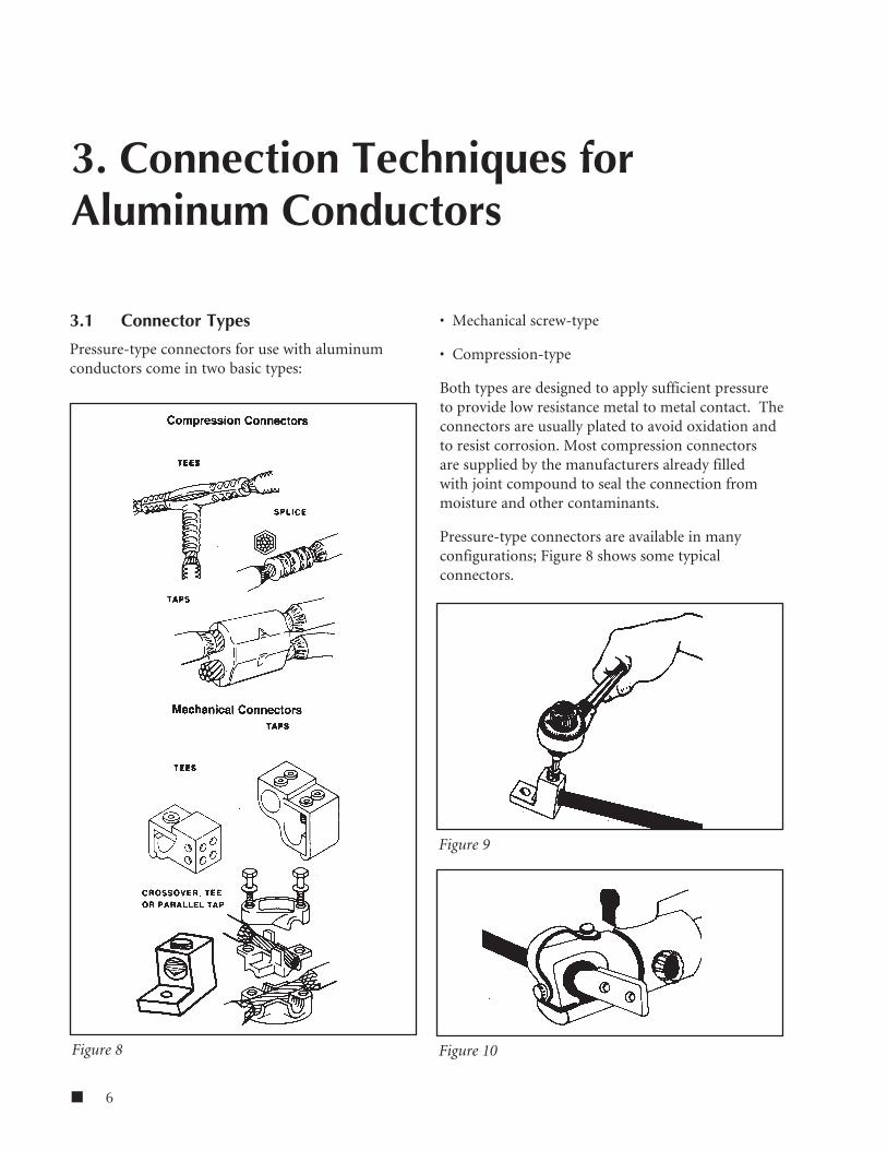
3.1 Connector Types
Pressure-type connectors for use with aluminum conductors come in two basic types:
• Mechanical screw-type
• Compression-type
Both types are designed to apply sufficient pressure to provide low resistance metal to metal contact. The connectors are usually plated to avoid oxidation and to resist corrosion. Most compression connectors are supplied by the manufacturers already filled with joint compound to seal the connection from moisture and other contaminants.
Pressure-type connectors are available in many configurations; Figure 8 shows some typical connectors.
3. Connection Techniques for Aluminum Conductors
Figure 8
Figure 9
Figure 10
7 n
Standard for Installing Aluminum Building Wire and Cable NECA/AA 104
3.1.1 Listing and marking
Pressure-type connectors listed for use with both aluminum and copper conductors are marked AL7CU or AL9CU (or CU7AL or CU9AL).
NOTE: Pressure-type connectors rated for 6 AWG or smaller conductors may have the markings on the connector, the unit container, or an information sheet packed in the unit container. Also, The AL7CU or AL9CU marking is not required on equipment connectors. However, the equipment bears a marking, such as AL-CU, indicating that they are suitable for both aluminum and copper conductors.
Connectors listed for use with aluminum conductors are listed in the UL Electrical Construction Equipment Directory. The category name for these connectors is “Wire Connectors and Soldering Lugs (ZMVV).”
3.1.2 Installation procedure – mechanical screw-type connectors
Follow these general procedures to install connectors. All manufacturers’ instructions should also be followed:
a) Use listed AL7CU or AL9CU connectors sized to accept aluminum conductors of the ampacity specified.
b) Using a suitable stripping tool to avoid damage to the conductor, remove insulation from the required length of the conductor.
c) Wire brush the conductor and apply a Listed joint compound.
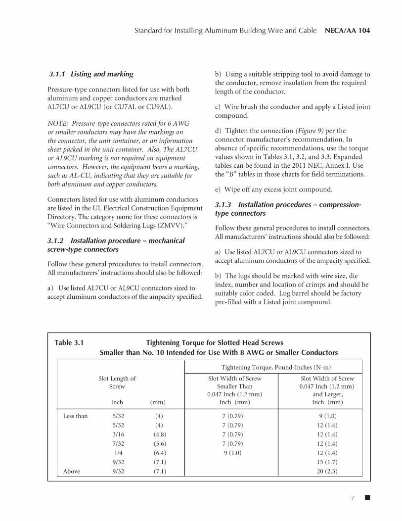
d) Tighten the connection (Figure 9) per the connector manufacturer’s recommendation. In absence of specific recommendations, use the torque values shown in Tables 3.1, 3.2, and 3.3. Expanded tables can be found in the 2011 NEC, Annex I. Use the “B” tables in those charts for field terminations.
e) Wipe off any excess joint compound.
3.1.3 Installation procedures – compression-type connectors
Follow these general procedures to install connectors. All manufacturers’ instructions should also be followed:
a) Use listed AL7CU or AL9CU connectors sized to accept aluminum conductors of the ampacity specified.
b) The lugs should be marked with wire size, die index, number and location of crimps and should be suitably color coded. Lug barrel should be factory pre-filled with a Listed joint compound.
Table 3.1 Tightening Torque for Slotted Head Screws Smaller than No. 10 Intended for Use With 8 AWG or Smaller Conductors
Tightening Torque, Pound-Inches (N-m)
Slot Length of Slot Width of Screw Slot Width of Screw Screw Smaller Than 0.047 Inch (1.2 mm) 0.047 Inch (1.2 mm) and Larger,
Inch (mm) Inch (mm) Inch (mm)
Less than 5/32 (4) 7 (0.79) 9 (1.0)
5/32 (4) 7 (0.79) 12 (1.4)
3/16 (4.8) 7 (0.79) 12 (1.4)
7/32 (5.6) 7 (0.79) 12 (1.4)
1/4 (6.4) 9 (1.0) 12 (1.4)
9/32 (7.1) 15 (1.7)
Above 9/32 (7.1) 20 (2.3)

n 8
NECA/AA 104 Standard for Installing Aluminum Building Wire and Cable
c) Using a suitable stripping tool, to avoid damage to the conductor, remove insulation from the required length of the conductor.
d) Wire brush the conductor.
e) Crimp the connection (Figure 10) per connector manufacturer’s recommendations.
f) Wipe off any excess joint compound.
g) If required, tape the joint as described in 2.3 or apply the insulating enclosure, if provided, with the connector.
3.2 Joint Compound
Conductor Termination Compounds (commonly known as joint compounds or oxide inhibitors) are used on splice and termination connections of aluminum, copper-clad aluminum, and copper conductors where needed to retard oxidation at conductor/connector interface. Joint compounds are produced in many varieties, all with special properties appropriate for their intended use. Compound should be compatible with conductor insulation and components used for splicing and terminating. These compounds do not have a deleterious effect on the conductor metal, insulation or equipment when used
in accordance with the manufacturer’s installation instructions.
A Listed joint compound is applied to the bare conductor after it has been wire brushed. A coating of joint compound remains on the surface of the conductors, preventing moisture or other contaminants from contacting the connection area.
NOTE: Some joint compounds contain coarse grit or metallic particles, which make them unsuitable for flat-bar connections.
3.3 Terminal Lugs
Listed terminal lugs marked AL7CU or AL9CU are used to connect aluminum conductors to transformers, switches, bus bars, motors and other equipment. Aluminum terminals are usually plated to resist corrosion, and these plated connectors should not be wire brushed or abraded.
Like connectors, terminal lugs are of two basic types: mechanical screw type and compression type applied by tool and die. Figure 11 shows typical terminal lugs. They are applied to the conductor ends in the same manner described in 3.1.
Care should be taken that conductor temperature and ampacity ratings are compatible with the terminals and equipment to which they are to be connected. See the markings on the equipment, the instructions furnished with the equipment, or the installation instructions (drawings) for the project for these details.
3.3.1 Installation procedure
When all components are aluminum (bus, studs, and lugs), aluminum bolts should be used to make the connections. Follow these steps:
a) Use the components furnished or specified by the equipment manufacturer. These may include:
• Aluminum bolts should be anodized alloy 2024-T4 and conform to ANSI B18.2.1 specifications and to ASTM B211 or B221 chemical and mechanical property limits.
Table 3.2 Tightening Torque for Socket Head Screws
Socket Size Across Tightening Torque, Flats Pound-Inches (N-m)
Inch (mm) Inch (mm)
1/8 (3.2) 45 (5.1)
5/32 (4.0) 100 (11.3)
3/16 (4.8) 120 (13.6)
7/32 (5.6) 150 (16.9)
1/4 (6.4) 200 (22.6)
5/16 (7.9) 275 (31.1)
3/8 (9.5) 375 (42.4)
1/2 (12.7) 500 (56.5)
9/16 (14.3) 600 (67.8)
9 n
Standard for Installing Aluminum Building Wire and Cable NECA/AA 104
• Nuts should be aluminum alloy 6061-T6 or 6262-T9 and conform to ANSI B18.2.2.
• Washers should be flat aluminum alloy 2024-T4, Type A plain, standard wide series conforming to ANSI B27.2. SAE or narrow series washers should not be used.
b) Hardware should be assembled as shown in Figure 12.
• Lubricate all hardware with silicon spray or other suitable lubricant before tightening. If bolts are not lubricated, torque may vary widely and result in high contact resistance at joints.
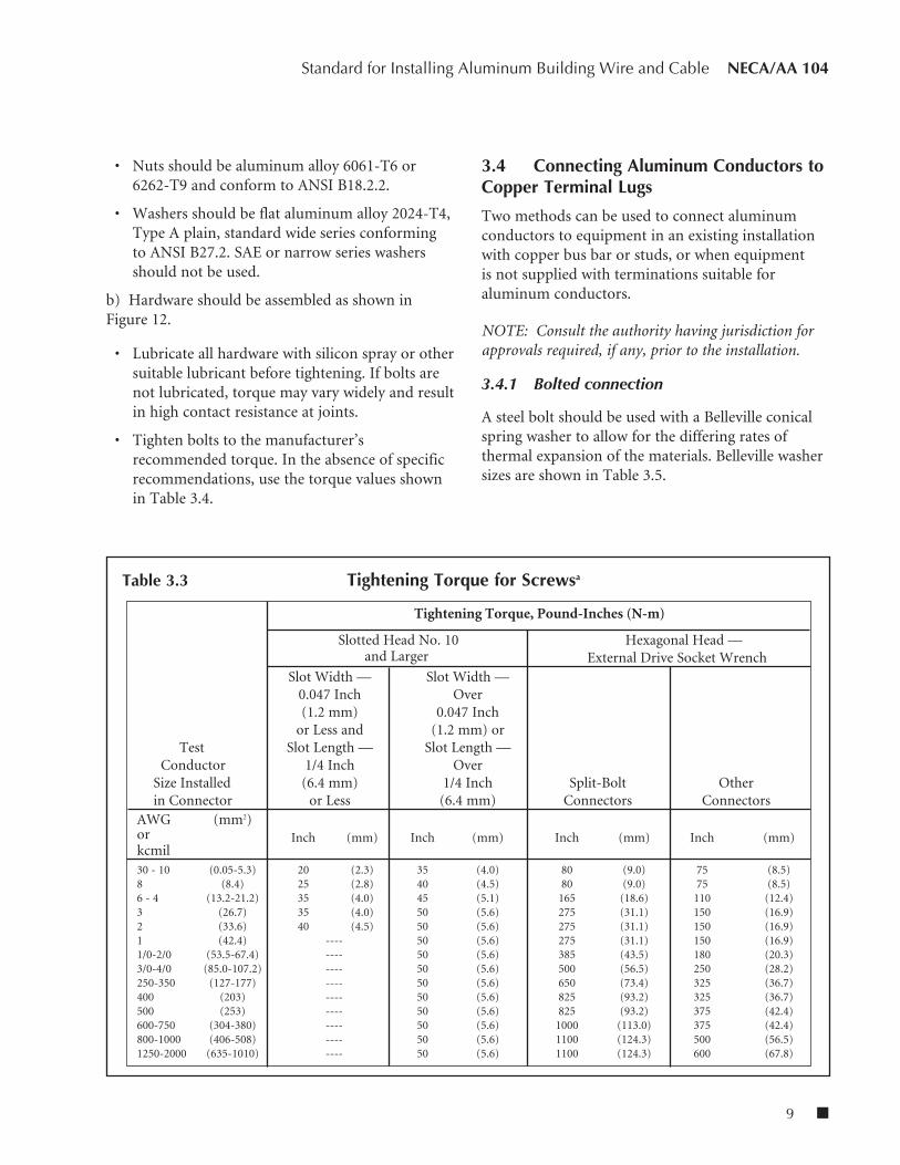
• Tighten bolts to the manufacturer’s recommended torque. In the absence of specific recommendations, use the torque values shown in Table 3.4.
3.4 Connecting Aluminum Conductors to Copper Terminal Lugs
Two methods can be used to connect aluminum conductors to equipment in an existing installation with copper bus bar or studs, or when equipment is not supplied with terminations suitable for aluminum conductors.
NOTE: Consult the authority having jurisdiction for approvals required, if any, prior to the installation.
3.4.1 Bolted connection
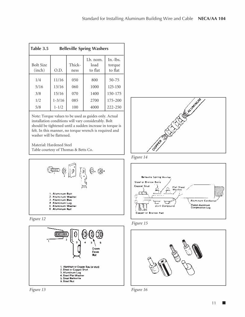
A steel bolt should be used with a Belleville conical spring washer to allow for the differing rates of thermal expansion of the materials. Belleville washer sizes are shown in Table 3.5.
Table 3.3 Tightening Torque for Screwsa
Tightening Torque, Pound-Inches (N-m)
Slotted Head No. 10 Hexagonal Head — and Larger External Drive Socket Wrench
Slot Width — Slot Width — 0.047 Inch Over (1.2 mm) 0.047 Inch or Less and (1.2 mm) or Test Slot Length — Slot Length — Conductor 1/4 Inch Over Size Installed (6.4 mm) 1/4 Inch Split-Bolt Other in Connector or Less (6.4 mm) Connectors ConnectorsAWG (mm2)or Inch (mm) Inch (mm) Inch (mm) Inch (mm)kcmil30 - 10 (0.05-5.3) 20 (2.3) 35 (4.0) 80 (9.0) 75 (8.5)8 (8.4) 25 (2.8) 40 (4.5) 80 (9.0) 75 (8.5)6 - 4 (13.2-21.2) 35 (4.0) 45 (5.1) 165 (18.6) 110 (12.4)3 (26.7) 35 (4.0) 50 (5.6) 275 (31.1) 150 (16.9)2 (33.6) 40 (4.5) 50 (5.6) 275 (31.1) 150 (16.9)1 (42.4) ---- 50 (5.6) 275 (31.1) 150 (16.9)1/0-2/0 (53.5-67.4) ---- 50 (5.6) 385 (43.5) 180 (20.3)3/0-4/0 (85.0-107.2) ---- 50 (5.6) 500 (56.5) 250 (28.2)250-350 (127-177) ---- 50 (5.6) 650 (73.4) 325 (36.7)400 (203) ---- 50 (5.6) 825 (93.2) 325 (36.7)500 (253) ---- 50 (5.6) 825 (93.2) 375 (42.4)600-750 (304-380) ---- 50 (5.6) 1000 (113.0) 375 (42.4)800-1000 (406-508) ---- 50 (5.6) 1100 (124.3) 500 (56.5)1250-2000 (635-1010) ---- 50 (5.6) 1100 (124.3) 600 (67.8)

n 10
NECA/AA 104 Standard for Installing Aluminum Building Wire and Cable
a) Use the components furnished or specified by the equipment manufacturer. These may include:
• Steel bolts should be plated or galvanized, medium carbon steel, heat treated, quenched and tempered equal to ASTM A-325 or SAE grade 5.
• Nuts should be heavy semi-finished hexagonal, conforming to ANSI B18.2.2, with unified coarse series (U.C.) threads, class 2B.
• Flat washers should be steel, Type A, plain standard wide series conforming to ANSI B27.2. SAE or narrow series washers should not be used.
• Hardware should be assembled as shown in Figure 13.
• All hardware should be lubricated with silicon spray or other suitable lubricant before tightening.
b) Tighten bolts to the equipment manufacturer’s recommended torque.
3.4.2 Gutter splice
A “gutter splice” may be used to connect the aluminum conductor. The aluminum conductor is spliced to a short length of copper conductor using an AL7CU or AL9CU compression type connector as shown in Figure 14. The copper conductor stub is then connected to the equipment terminal. Where it is not practical to use a gutter splice, use one of the following methods:
a) Use listed AL7CU or AL9CU adapter fittings specifically designed for this purpose (Figure 16), or
b) Use large compression type lugs, preferably with two holes, to connect large aluminum conductors (500 kcmil and up) to heavy equipment having copper terminal studs and/or pads.
• When using aluminum bolts and nuts, only a heavy flat washer, bearing on the aluminum lug is necessary as shown in Figure 15, or
• With other than aluminum bolts, use Belleville spring washers and heavy flat washers arranged
as shown in Figure 13.
Figures 17-21 show typical connections of aluminum conductors to equipment terminal lugs in similar situations.
Figure 11
Table 3.4 Lug Bolting Torque
Bolt Diameter Tightening Torque (inch) (pound-feet)
1/4 or less 6
5/16 11
3/8 19
7/16 30
1/2 40
5/8 or more 55
11 n
Standard for Installing Aluminum Building Wire and Cable NECA/AA 104
Figure 13 Figure 16
Figure 14
Figure 15Figure 12
Table 3.5 Belleville Spring Washers
Lb. nom. In.-lbs. Bolt Size Thick- load torque (inch) O.D. ness to flat to flat
1/4 11/16 050 800 50-75
5/16 13/16 060 1000 125-150
3/8 15/16 070 1400 150-175
1/2 1-3/16 085 2700 175-200
5/8 1-1/2 100 4000 222-250
Note: Torque values to be used as guides only. Actual installation conditions will vary considerably. Bolt should be tightened until a sudden increase in torque is felt. In this manner, no torque wrench is required and washer will be flattened.
Material: Hardened SteelTable courtesy of Thomas & Betts Co.

n 12
NECA/AA 104 Standard for Installing Aluminum Building Wire and Cable
Figure 19
Figure 21
Figure 20Figure 17
Figure 18

13 n
1. Scope
4.1 General
Aluminum service entrance conductors are spliced to aluminum service drop cable as described in 2.3. Aluminum service entrance conductors should be spliced to copper service drop cables using listed adapter connectors.
Bare aluminum conductors are permitted for system grounding by NEC Article 250. Listed ground clamps for use with aluminum grounding electrode conductors are marked AL or AL-CU. There is no temperature rating associated with grounding clamps. Therefore, a “7” or “9” is not included in the marking on the clamps.
Equipment grounding conductors of bare or insulated aluminum are permitted by NEC Article 250. Where used, bare aluminum conductors shall not come in direct contact with masonry or the earth or where subject to conditions corrosive to aluminum. Where terminated outside, aluminum conductor terminations shall not be made within 18 inches (460 mm) of the earth.
Insulated aluminum equipment grounding conductors may be used in nearly any application, including direct buried, installed in raceways, or within cable assemblies. Bare aluminum equipment grounding conductors may be installed in raceways and cable assemblies or used in overhead installations.
Figure 22 shows a typical medium-size service entrance.
4.2 Residential
Type SE aluminum cable is commonly used for residential service entrances and feeders. It is connected to the utility service drop cable as
described in 4.1. Meter boxes and electrical panels are available with aluminum AL7CU or AL9CU terminals for connection to Type SE aluminum service entrance cable. For dwellings with a 120/240 volt, single-phase service, NEC Table 310.15(B)(7) may be used to size the service entrance and feeder conductors.
Type SE aluminum cable is also commonly used for large branch circuits within homes, such as dryers, ranges and water heaters. Circuit breakers are listed for use with copper or aluminum conductors, and receptacles for 30 amp and larger loads are typically listed for both copper and aluminum conductors.
For interior branch circuits and feeders, Type SE cable must comply with the installation requirements for non-metallic sheathed cable, except for the ampacity limitations. Type SE cable is normally listed for 75°C and contains 90°C conductors.
4. Service Entrances Using Aluminum Cables
Figure 22
n 14
NECA/AA 104 Standard for Installing Aluminum Building Wire and Cable
When installed in thermal insulation, Type SE cable is limited to 60°C, but may be derated from the maximum conductor temperature rating.
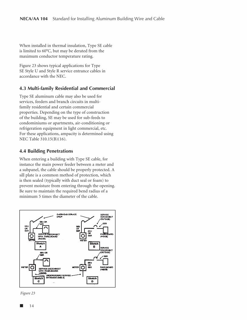
Figure 23 shows typical applications for Type SE Style U and Style R service entrance cables in accordance with the NEC.
4.3 Multi-family Residential and Commercial
Type SE aluminum cable may also be used for services, feeders and branch circuits in multi-family residential and certain commercial properties. Depending on the type of construction of the building, SE may be used for sub-feeds to condominiums or apartments, air-conditioning or refrigeration equipment in light commercial, etc. For these applications, ampacity is determined using NEC Table 310.15(B)(16).
4.4 Building Penetrations
When entering a building with Type SE cable, for instance the main power feeder between a meter and a subpanel, the cable should be properly protected. A sill plate is a common method of protection, which is then sealed (typically with duct seal or foam) to prevent moisture from entering through the opening. Be sure to maintain the required bend radius of a minimum 5 times the diameter of the cable.
Figure 23

15 n
1. Scope
5.1 General
Design procedures for aluminum alloy building wire products are typical of the procedures required for electrical wire and cable products. It is recommended to verify that the choice of aluminum conductors is included in the design of an installation.
5.2 Aluminum Conductor Ampacities and Sizes
Table 5.1 lists ampacities of aluminum and copper-clad aluminum conductors.
Table 5.2 lists sizes of aluminum and copper-clad aluminum conductors permitted for 120/240 volt, 3-wire, single-phase dwelling services and feeders.
NOTE: Using large-size single conductors for feeders sometimes results in excessive conductor and conduit cost. The use of smaller conductors in parallel to provide the required ampacity may prove to be more efficient.
5.3 Conduit Fill Requirements
Table 5.3 provides the nominal conductor dimensions for compact stranded aluminum alloy conductors. Based on these dimensions, Tables C1A through C12A of NEC Appendix C provide the maximum number of compact aluminum alloy building wire conductors that can be installed in various types of conduits. For example, Table 5.4 shows maximum number of compact stranded conductors permitted in electrical metallic tubing (EMT).
In most cases, there is no need to change the size of a raceway from that needed for copper conductors when using the electrically equivalent size of compact stranded aluminum alloy building wire conductors.
NOTE: Since copper conductors are generally made using compressed or concentric stranded construction and aluminum alloy building wire conductors are generally made using compact stranded construction, the overall diameter of compact stranded electrically equivalent aluminum conductors is comparable to the copper conductors.
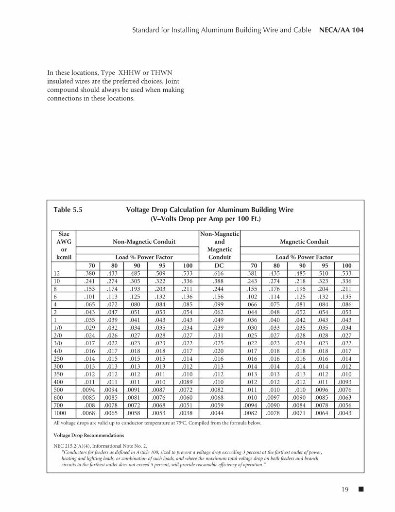
5.4 Voltage Drop Considerations
Voltage drop is an important element in the design of an electrical installation. The NEC recommends limiting voltage drop to 3 percent for either branch circuits or feeders, and 5 percent for feeders and branch circuits together.
Table 5.5 lists voltage drop for aluminum building wire in sizes for 12 AWG to 1000 kcmil, at power factors ranging from 70 to 100 percent. Table 5.6 lists resistances of aluminum conductors. Table 5.7 lists inductive reactance in magnetic and non-magnetic conduits, thus making it possible to calculate voltage drops.
5.5 Temperature Conditions
The NEC gives derating factors for ambient temperatures above 30oC (86oF).
In general, operation at high conductor temperatures should be avoided. Voltage drop introduced by higher resistances in conductors at higher operating temperatures outweighs the advantage of a slightly higher allowable ampacity permitted by the higher temperature rating of the conductor.
It should be noted that equipment rated up to 600 volts is evaluated using ampacities from NEC Table 310.15(B)(16) (60oC or 75oC column) in accordance with 110.14 and applicable UL standards. Thus, the ampacities of conductors suitable for operation at
5. Designing with Aluminum

n 16
NECA/AA 104 Standard for Installing Aluminum Building Wire and Cable
Table 5.1 Allowable Ampacities of Insulated Aluminum and Copper-Clad Aluminum Conductors Rated Up T o and Including 0 through 2000 Volts, 60° to 90°C (140° to 194°F) Based on Ambient Temperature of 30°C (86°F)*
Not More Than Three Conductors in a Raceway Single Conductor in Free Air or Cable or Earth (Directly Buried)
60oC Rating 75oC Rating 90oC Rating 60oC Rating 75oC Rating 90oC RatingSize THW THW-2 THW THW-2AWG THWN THHN THWN THHNor RHW THWN-2 RHW THWN-2kcmil TW XHHW RHH TW XHHW RHH RHW-2 RHW-2 XHHW-2 XHHW-2 Alum. Alum. Alum. Alum. Alum. Alum.12** 15 20 25 25 30 35
10** 25 30 35 35 40 458 35 40 45 45 55 606 40 50 55 60 75 854 55 65 75 80 100 1153 65 75 85 95 115 1302 75 ***90 ***100 110 135 1501 85 ***100 ***115 130 155 1751/0 100 ***120 ***135 150 180 2052/0 115 ***135 ***150 175 210 2353/0 130 ***155 ***175 200 240 2704/0 150 ***180 ***205 235 280 315250 170 ***205 ***230 265 315 355300 195 ***230 ***260 290 350 395350 210 ***250 ***280 330 395 445400 225 270 305 355 425 480500 260 ***310 ***350 405 485 545600 285 ***340 ***385 455 540 615700 315 375 425 500 595 670750 320 385 435 515 620 700800 330 395 445 535 645 725900 355 425 480 580 700 7901000 375 445 500 625 750 845
*Refer to 310.15 (B)(2) for the ampacity correction factors where the ambient temperature is other than 30°C (86°F).
**Refer to 240.4(D) for conductor overcurrent protection limitations.
***See Table 5.2.
Correction Factors for Room Temperatures over 30oC (86oF)
oC oF 60oC Rating 75oC Rating 90oC Rating
31-35 85-95 .91 .94 .96 36-40 97-104 .82 .88 .91 41-45 105-113 .71 .82 .87 46-50 114-122 .58 .75 .82 51-60 124-140 .58 .71 61-70 142-158 .35 .58 71-80 160-176 .41

17 n
Standard for Installing Aluminum Building Wire and Cable NECA/AA 104
90oC may be used to perform the applicable derating calculations such that the resulting ampacity of the conductors is not greater than their ampacity at 60o or 75oC to match the temperature rating of the equipment.
5.6 Moisture Conditions
Properly installed aluminum cables and conductors will operate satisfactorily in damp and wet locations.
Table 5.2 120/240 Volt, 3-Wire, Single-Phase Dwelling Services and Feeders
For individual dwelling units of one-family, two-family, and multifamily dwellings, conductors, as listed in Table 310.15(B)(7), shall be permitted as 120/240-volt, 3-wire, single-phase service-entrance conductors, service-lateral conductors, and feeder con-ductors that serve as the main power feeder to each dwelling unit and are installed in raceway or cable with or without an equip-ment grounding conductor. For application of this section, the main power feeder shall be the feeder between the main disconnect and the panelboard that supplies, either by branch circuits or by feeders, or both, all loads that are part of associated with the dwelling unit. The feeder conductors to a dwelling unit shall not be required to have an allowable ampacity rating greater than their service-entrance conductors, provided the requirements of 215.2, 220.61, and 230.42 are met.
Conductor Types and SizesRH, RHH, RHW, RHW-2, THHN, THHW, THW, THW-2, THWN, THWN-2, XHHW, XHHW-2, SE, USE, USE-2
Aluminum or Service or FeederCopper-Clad Aluminum Rating in Amps
AWG2 1001 1101/0 1252/0 1503/0 1754/0 200250 kcmil 225300 kcmil 250350 kcmil 300500 kcmil 350600 kcmil 400
Table 5.1 (continued)
More than Three Current-Carrying Conductors in a Raceway or Cable. Where the number of current-carrying conductors in a raceway or cable exceeds three, the allowable ampacities shall be reduced as shown in the following table:
Number of Current-Carrying Percent of Values in Tables as AdjustedConductors for Ambient Temperature if Necessary
4 through 6 807 through 9 7010 through 20 5021 through 30 4531 through 40 4041 and above 35
A neutral conductor, which carries only the unbalance current from other conductors as in the case of normally balanced circuits of three or more conductors, shall not be counted in determining ampacities as described above. In a 3-wire circuit, consisting of two phase wires and the neutral of a 4-wire, three-phase wye connected system, a common conductor carries approximately the same current as the other conductors and shall be counted in determining ampacities.

n 18
NECA/AA 104 Standard for Installing Aluminum Building Wire and Cable
Table 5.3 Nominal Dimensions1, Areas, and Mass/1000 ft. for Common Aluminum Building Wire
Bare Conductor2 Type THHN, THWN-2, THWN2,3 Type XHHW-2, XHHW2,4
Size Approx. Approx. Nominal Approx. Approx. Nominal Size AWG or Dia. Dia. Area Mass Dia. Area Mass AWG or KCMIL Inches Inches Sq. In. Lb./1000 ft. Inches Sq. In. Lb./1000 ft. KCMIL
8 .134 — — — .224 .0394 28 86 .169 .240 .0452 37 .260 .0530 40 64 .213 .305 .0730 60 .305 .0730 60 42 .268 .360 .1017 90 .360 .1017 85 21 .299 .415 .1352 115 .415 .1352 110 11/0 .336 .450 .1590 140 .450 .1590 135 1/02/0 .376 .495 .1924 170 .490 .1885 165 2/03/0 .423 .540 .2290 210 .540 .2290 200 3/04/0 .475 .595 .2780 255 .590 .2733 245 4/0250 .520 .670 .3525 310 .660 .3421 295 250300 .570 .720 .4071 360 .715 .4015 350 300350 .616 .770 .4656 415 .760 .4536 400 250400 .659 .815 .5216 465 .800 .5026 450 400500 .736 .885 .6151 570 .880 .6082 555 500600 .813 .985 .7620 690 .980 .7542 675 600700 .877 1.050 .8659 795 1.050 .8659 780 700750 .908 1.075 .9076 845 1.090 .9331 830 7501000 1.060 1.255 1.2370 1100 1.230 1.1882 1085 1000
1 Dimensions are from industry sources.2 Compact conductor per ASTM B 801. Section 310.106(B) of the NEC calls for AA 8000 series electrical grade aluminum alloy conductor material.3 Conductors type THHN, THWN-2 and THWN per UL 83.4 Conductors type XHHW and XHHW-2 per UL 44.
Table 5.4 Maximum Number of Aluminum Alloy Building Wire Conductors in Trade Sizes of Conduit or Tubing Insulation TypeConductor T T X X T T X X T T X X T T X X T T X X T T X X T T X X T T X X Conductor Size H H H H H H H H H H H H H H H H H H H H H H H H H H H H H H H H Size AWG or H W H H H W H H H W H H H W H H H W H H H W H H H W H H H W H H AWG or kcmil N N W W N N W W N N W W N N W W N N W W N N W W N N W W N N W W kcmil -2 -2 -2 -2 -2 -2 -2 -2 -2 -2 -2 -2 -2 -2 -2 -2
Conduit Trade Size (Electrical Metallic Tubing) 1 1-1/4 1-1/2 2 2-1/2 3 3-1/2 4
6 7 6 13 11 18 15 64 4 4 8 8 11 11 18 18 42 3 3 6 6 8 8 13 13 21 4 4 6 6 10 10 17 17 11/0 3 3 5 5 8 8 14 14 1/02/0 3 3 4 4 7 7 12 12 18 18 2/03/0 3 3 6 6 10 10 15 15 3/04/0 3 3 5 5 8 8 12 13 16 17 4/0250 4 4 6 7 10 10 13 13 250300 3 3 5 6 8 9 11 11 14 14 300350 3 3 5 5 7 8 10 10 12 13 350400 4 4 6 7 9 9 11 11 400500 4 4 5 6 7 7 9 9 500600 3 3 4 4 6 6 7 8 600700 4 4 5 5 7 7 700750 4 3 5 5 6 6 7501000 3 3 3 4 4 5 1000
* Per conduit fill requirements for compact conductors as permitted in NEC Chapter 9.
19 n
Standard for Installing Aluminum Building Wire and Cable NECA/AA 104
Table 5.5 Voltage Drop Calculation for Aluminum Building Wire (V–Volts Drop per Amp per 100 Ft.)
Size Non-Magnetic AWG Non-Magnetic Conduit and Magnetic Conduit or Magnetic kcmil Load % Power Factor Conduit Load % Power Factor 70 80 90 95 100 DC 70 80 90 95 10012 .380 .433 .485 .509 .533 .616 .381 .435 .485 .510 .53310 .241 .274 .305 .322 .336 .388 .243 .274 .218 .323 .3368 .153 .174 .193 .203 .211 .244 .155 .176 .195 .204 .2116 .101 .113 .125 .132 .136 .156 .102 .114 .125 .132 .1354 .065 .072 .080 .084 .085 .099 .066 .075 .081 .084 .0862 .043 .047 .051 .053 .054 .062 .044 .048 .052 .054 .0531 .035 .039 .041 .043 .043 .049 .036 .040 .042 .043 .0431/0 .029 .032 .034 .035 .034 .039 .030 .033 .035 .035 .0342/0 .024 .026 .027 .028 .027 .031 .025 .027 .028 .028 .0273/0 .017 .022 .023 .023 .022 .025 .022 .023 .024 .023 .0224/0 .016 .017 .018 .018 .017 .020 .017 .018 .018 .018 .017250 .014 .015 .015 .015 .014 .016 .016 .016 .016 .016 .014300 .013 .013 .013 .013 .012 .013 .014 .014 .014 .014 .012350 .012 .012 .012 .011 .010 .012 .013 .013 .013 .012 .010400 .011 .011 .011 .010 .0089 .010 .012 .012 .012 .011 .0093500 .0094 .0094 .0091 .0087 .0072 .0082 .011 .010 .010 .0096 .0076600 .0085 .0085 .0081 .0076 .0060 .0068 .010 .0097 .0090 .0085 .0063700 .008 .0078 .0072 .0068 .0051 .0059 .0094 .0090 .0084 .0078 .00561000 .0068 .0065 .0058 .0053 .0038 .0044 .0082 .0078 .0071 .0064 .0043
All voltage drops are valid up to conductor temperature at 75oC. Compiled from the formula below.
Voltage Drop Recommendations
NEC 215.2(A)(4), Informational Note No. 2,“Conductors for feeders as defined in Article 100, sized to prevent a voltage drop exceeding 3 percent at the farthest outlet of power, heating and lighting loads, or combination of such loads, and where the maximum total voltage drop on both feeders and branch circuits to the farthest outlet does not exceed 5 percent, will provide reasonable efficiency of operation.”
In these locations, Type XHHW or THWN insulated wires are the preferred choices. Joint compound should always be used when making connections in these locations.

n 20
NECA/AA 104 Standard for Installing Aluminum Building Wire and CableNECA 402 Recommended Practice for Installing and Maintaining Motor Control Centers
Table 5.6 Resistances of Aluminum Alloy Building Wire (Class B — concentric strands) (Ohms per 1000 feet)
Class B * 60 Hertz AC – 60oC * 60 Hertz AC – 75oC * 60 Hertz AC – 90oC Multi-Cond Multi-Cond. Multi-Cond. One Single Cable One Single Cable One Single Cable Conductor or 2 or 3 Conductor or 2 or 3 Conductor or 2 or 3 AWG DC in Air, Single DC in Air, Single DC in Air, Single or at Buried, Conductors at Buried, Conductors at Buried, Conductors kcmil 60oC or in in One 75oC or in in One 90oC or in in One Nonmetallic Metallic Nonmetallic Metallic Nonmetallic Metallic Conduit Conduit Conduit Conduit Conduit Conduit
12 3.08 3.08 3.08 3.24 3.24 3.24 3.41 3.41 3.4110 1.94 1.94 1.94 2.04 2.04 2.04 2.14 2.14 2.148 1.22 1.22 1.22 1.28 1.28 1.28 1.35 1.35 1.356 .767 .767 .767 .870 .870 .870 .847 .847 .8474 .482 .482 .482 .508 .508 .508 .533 .533 .5333 .383 .383 .383 .403 .403 .403 .423 .423 .4232 .303 .303 .303 .319 .319 .319 .335 .335 .3351 .241 .241 .241 .253 .253 .253 .266 .266 .2661/0 .191 .191 .191 .201 .201 .201 .211 .211 .2112/0 .151 .151 .151 .159 .159 .159 .167 .167 .1673/0 .120 .120 .121 .126 .126 .127 .132 .132 .1324/0 .0952 .0955 .0962 .100 .100 .101 .105 .105 .106250 .0805 .0807 .0821 .0847 .0849 .0864 .0889 .0891 .0907300 .0651 .0673 .0684 .0706 .0708 .0720 .0741 .0743 .0756350 .0576 .0578 .0593 .0605 .0607 .0623 .0635 .0638 .0654400 .0503 .0506 .0523 .0530 .0533 .0551 .0556 .0559 .0578500 .0403 .0406 .0427 .0424 .0427 .0449 .0445 .0448 .0472600 .0336 .0339 .0363 .0353 .0357 .0381 .0371 .0375 .0401700 .0288 .0292 .0320 .0303 .0307 .0336 .0318 .0322 .0353750 .0268 .0272 .0300 .0282 .0286 .0316 .0296 .0300 .0332800 .0252 .0256 .0287 .0265 .0270 .0302 .0278 .0283 .0317900 .0224 .0229 .0260 .0235 .0240 .0273 .0247 .0252 .02861000 .0201 .0206 .0239 .0212 .0218 .0252 .0222 .0228 .0264
* Resistances calculated from NEC Chapter 9.

21 n
Standard for Installing Aluminum Building Wire and Cable NECA/AA 104
Table 5.7 Reactances of Aluminum Alloy Building Wire Inductive Reactance to neutral Ohms Per 1000 Feet — 60 Hertz Non-Magnetic Conduit
Conductor Covering Thickness (Insulation + Cover) in Mils Size AWG or kcmil 45 60 80 95 100 125 140 155 170 190
12* .0473 .0517 .0555 .0590 10* .0440 .0480 .0516 .0543 .0576 8 .0410 .0446 .0480 .0507 .0534 6 .0403 .0431 .0455 .0476 .0497 4 .0379 .0402 .0422 .0443 .0477 2 .0356 .0377 .0396 .0414 .0424 1 .0368 .0381 .0399 .0414 .0429 .0443 1/0 .0356 .0371 .0389 .0399 .0416 .0427 2/0 .0348 .0363 .0376 .0389 .0402 .0414 3/0 .0340 .0354 .0368 .0376 .0391 .0399 4/0 .0332 .0345 .0356 .0366 .0377 .0386 250 .0338 .0350 .0359 .0368 .0377 .0389 .0397300 .0330 .0341 .0350 .0359 .0368 .0379 .0391350 .0325 .0338 .0343 .0356 .0363 .0373 .0381400 .0324 .0336 .0341 .0354 .0360 .0369 .0377500 .0318 .0325 .0332 .0341 .0348 .0356 .0366600 .0322 .0329 .0336 .0343 .0350 .0357700 .0318 .0325 .0332 .0338 .0345 .0353750 .0314 .0321 .0329 .0335 .0342 .0348
Magnetic ConduitConductor Covering Thickness (Insulation + Cover) in Mils
Size AWG or kcmil 45 60 80 95 100 125 140 155 170 190
12* .0591 .0646 .0694 .0738 10* .0550 .0600 .0645 .0685 .0720 8 .0513 .0558 .0600 .0634 .0667 6 .0504 .0538 .0568 .0595 .0621 4 .0474 .0502 .0528 .0553 .0597 2 .0445 .0471 .0495 .0517 .0532 1 .0460 .0477 .0499 .0517 .0537 .0553 1/0 .0445 .0463 .0486 .0499 .0520 .0534 2/0 .0435 .0454 .0471 .0486 .0502 .0517 3/0 .0426 .0442 .0460 .0471 .0489 .0499 4/0 .0415 .0432 .0445 .0457 .0471 .0483 250 .0423 .0438 .0448 .0460 .0471 .0486 .0496300 .0412 .0426 .0438 .0448 .0460 .0474 .0489350 .0406 .0423 .0429 .0445 .0454 .0466 .0477400 .0405 .0420 .026 .0442 .0450 .0462 .0471500 .0397 .0406 .0415 .0426 .0435 .0445 .0457600 .0402 .0411 .0420 .0429 .0438 .0447700 .0397 .0406 .0415 .0423 .0432 .0441750 .0393 .0402 .0411 .0418 .0427 .0435
* SOLID
Note: The values in the above tables are based upon Class B concentric compressed stranded conductors. These values are suitable for use with Class B concentric compact stranded conductors of aluminum building wire products.

n 22
1. Scope
6.1 AC Cable Construction
Type AC cable has 2, 3, or 4 insulated conductors in sizes ranging from 14 AWG - 1 AWG for copper and 12 AWG - 1 AWG aluminum or copper clad
aluminum. These conductors are individually wrapped with moisture-resistant, fire-retardant paper. The grouped conductors are covered with an armor of interlocking metal tape. Type AC cable is
6. Type AC Aluminum Cables
Table 6.1 Aluminum Armored (Type AC) Cable
Listed per UL 4 in accordance with NEC Article 320.Cable tray rated. Used in dry locations only.Permitted for branch circuits and feeders in both exposed and concealed work.Requires saddle or clamp type connector, not a set-screw type connector.
Aluminum Armored Cable
AWG Size-No. of
Cdr. (Copper)
Type of Circuit
Conductor
Weight Per 1000
Feet
Approximate Coil
Length in Feet
Reel Length
in Feet
14-2
14-3
14-4
THHN Solid
93
111
133
250
250
250
1000
1000
1000
12-2
12-3
12-4
THHN Solid
112
140
167
250
250
250
1000
1000
1000
10-2
10-3
10-4
THHN Solid
146
189
234
250
250
250
500
500
500
8-2
8-3
8-4
THHN Stranded
216
285
364
200
200
200
500
500
500
6-2
6-3
6-4
THHN Stranded
304
414
530
100
100
100
500
500
500
4-2
4-3
4-4
THHN Stranded
429
613
793
100
100
100
500
500
500
2-2
2-3
2-4
THHN Stranded
636
938
1207
100
100
100
500
500
500

23 n
Standard for Installing Aluminum Building Wire and Cable NECA/AA 104
rated up to 600 volts. Aluminum armored cable is marked “Aluminum Armored.”
See Table 6.1 for typical constructions of AC Cable. There are three types of armored cable:
TYPE ACT: Armored cable having 60oC (140oF) conductors with PVC insulation suitable for dry locations.
TYPE ACTH: Armored cable having 75oC (167oF) conductors with PVC insulation suitable for dry locations.
TYPE ACTHH: Armored cable having 90oC (194oF) type THHN conductors. Where this cable is installed in thermal insulation, its ampacity is limited to that of 60oC (140oF) conductors.
6.2 AC Cable Applications
Type AC cable is used primarily for branch circuits and feeders in dry locations where it is not subject to physical damage.
6.3 AC Cable Terminations
Following these steps to connect type AC cable to an outlet box or other enclosure:
a) Remove the armor using a fine tooth hacksaw or a special tool to cut through a single convolution of armor. The cut piece of armor is then “unscrewed” to remove it from the twisted conductors.
b) Removing a 175 mm (7 in.) length of armor is usually sufficient for connections within an outlet box. A longer lead may be necessary where entering a panelboard enclosure where the conductor must run for some distance to reach its termination point.
c) Pull out the paper wrapped around the conductors to make room for the insulating bushing. This is supplied with the cable to protect the conductors from the sharp edge of the cut armor. This bushing must be in place before inserting the cable into the fitting or clamp within the box.
d) Connectors listed for armored cable have an inspection opening so that the insulating bushing can be seen after the fitting has been inserted into the box.
e) Use listed fittings or clamps to attach the armored cable to an outlet box or other enclosure. Outlet boxes are available with built-in clamps. Where standard knockouts are provided in an enclosure, the cable can be secured to these openings with a listed fitting of the proper size. This information will be provided on the fitting carton or packaging.
f) Aluminum armored cable is not permitted to be used with fittings in which the set screw directly contacts the aluminum armor.
6.4 AC Cable Supports
The NEC requires that Type AC cable be secured at intervals not exceeding 1.4 meters (4-1/2 ft) by approved staples, straps, hangers, or suitable supporting hardware. In addition, it is required to be secured within 300 mm (12 in.) of every outlet box, junction box, cabinet or fitting.
The NEC allows exceptions to these rules where the cable is fished, where flexibility is necessary and where the cable supplies a lighting fixture or equipment within an accessible ceiling.
6.5 Fishing AC Cable
The NEC permits type AC armored cable to be run or fished within the air voids of masonry block or tile walls, where such walls are not located below grade or subject to excessive moisture. For concealed work in finished buildings or finished panels for prefabricated buildings where supporting of the cable is impracticable, it is permissible to fish the cable between access points.
6.6 AC Cable Grounding
Type AC cable armor is designed to serve as the equipment grounding conductor for the circuit(s) contained within the cable. To improve armor conductivity, a bond strip of copper or aluminum is placed inside the cable in direct contact with the armor throughout its entire length.
n 24
NECA/AA 104 Standard for Installing Aluminum Building Wire and Cable
Listed fittings for armored cable provide the necessary conductance to provide an adequate equipment grounding circuit. No termination requirements apply to the internal bond strip. Bend this strip back over the armor so that it is secured under the clamping means applied to the armor.
An additional green insulated equipment grounding conductor may be included with the circuit conductors to provide an isolated ground for data processing equipment or a redundant ground for circuits in health care facilities.
6.7 AC Cable Ampacities
NEC Table 310.15(B)(16) lists ampacities for Type AC cables. Derating factors apply when more than three current carrying conductors are present in the cable. Correction factors apply when the ambient temperature exceeds 30°C (86°F).

25 n
1. Scope
7.1 MC Cable Construction
Type MC cable has one or more insulated conductors ranging from 18 AWG (copper) or 12 AWG (alumi-num) up to 2000 kcmil. Copper conductors are commonly used in the smaller sizes, while the large-size cables are available with either copper or aluminum conductors. The conductor bundle is available with or without an overall wrap of paper or plastic. Standard ratings for MC cable include 600 volts, 2000 volts, and 5000 - 35,000 volts, which are covered under the listing for Type MV.
Type MC cable is available with two types of armor:
1. Interlocking steel or aluminum tape, with an integral bare equipment grounding conductor, and
2. Smooth or corrugated tube armor, which may be constructed of steel, aluminum or copper.
The interlocking metal tape construction is available with a grounding/bonding conductor that in combination with the armor serves as the equipment grounding path. Both configurations can also be supplied with an integral insulated grounding conductor.
Table 7.1 provides nominal dimensions and other construction details of Type MC Cable with Type XHHW-2 compact aluminum alloy conductors.
7.2 MC Cable Applications
MC cable is permitted, under various NEC Articles, to be used for a wide range of applications including branch circuits, feeders, service conductors, control circuit, wet locations, direct burial, places of public assembly, health care facilities, and certain hazardous locations.
7.3 MC Cable Fittings
MC cable fittings have a shoulder to protect the inside conductors from any sharp edge that may be present on the cut end of the armor. It is important that fittings be listed for use with the particular type of cable with which they are used.
7.4 MC Cable Supports
The NEC requires that Type MC cable be supported and secured at intervals not exceeding 1.8 m (6 ft). Further, cables containing four or fewer conductors, sized no larger than 10 AWG are required to be secured within 300 mm (12 in.) of every box, cabinet, fitting, or other cable termination.
The NEC allows exceptions to these rules where the cable is fished, where flexibility is necessary and where the cable supplies a lighting fixture or equipment within an accessible ceiling.
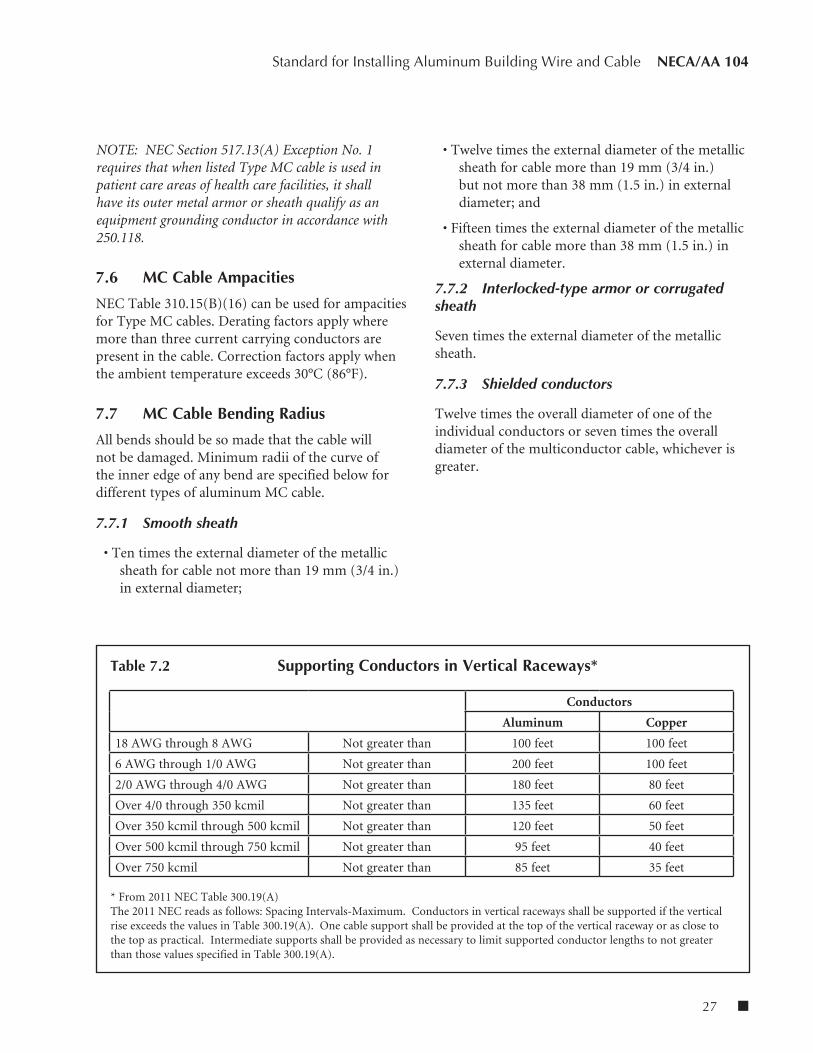
In vertical installations, Type MC cable is typically supported and secured in accordance with the above requirement. Further, it is recommended that support be provided in the cable runs at distances similar to those used to support the conductors in raceways for vertical runs. See Table 7.2 for details.
7.5 MC Cable Grounding
For Type MC cable the equipment grounding conductor is the combined metallic sheath and all of the grounding conductors furnished in the cable. The interlocking metal tape construction is available with a grounding/bonding conductor that in combination with the armor serves as the equipment grounding path. For smooth or corrugated MC cable without an internal grounding conductor, the armor alone serves as the equipment grounding conductor. If a
7. Type MC Cable

n 26
NECA/AA 104 Standard for Installing Aluminum Building Wire and Cable
green insulated conductor is provided within the cable in addition to the required equipment grounding conductor, it may be used to supply an isolated ground
for data processing or a redundant ground for health care applications.
Table 7.1 Nominal Dimensions and Weights of Aluminum Armored Type MC with XHHW-2 Conductors
Nominal Nominal Conductor Diameter Reel Mass Conductor Size Sub- (Inches) Length Size (Net lbs/mft) Size (AWG/KCMIL) Assembly1
w/o JKT2 JKT3 (Feet) w/o JKT JKT w/o JKT JKT
(AWG/KCMIL)
THREE CONDUCTOR WITH GROUND
6-6-6-6 0.63 0.83 0.93 1000 36.22.18 36.22.18 254 336 64-4-4-6 0.72 0.93 1.03 1000 36.22.18 36.22.18 326 417 42-2-2-6 0.81 1.03 1.13 1000 38.22.20 42.28.20 422 522 21-1-1-4 0.94 1.16 1.26 1000 42.28.20 42.28.20 528 641 11/0-1/0-1/0-4 1.00 1.23 1.33 1000 42.25.20 42.28.20 610 729 1/02/0-2/0-2/0-4 1.05 1.28 1.38 1000 42.28.20 48.28.24 699 823 2/03/0-3/0-3/0-4 1.13 1.36 1.46 1000 48.28.24 48.28.24 824 956 3/04/0-4/0-4/0-2 1.27 1.51 1.63 1000 60.28.28 60.28.28 1060 1235 4/0250-250-250-2 1.38 1.63 1.75 500 48.28.30 48.28.30 1225 1414 250300-300-300-2 1.47 1.72 1.84 500 48.28.30 48.28.30 1400 1599 300350-350-350-2 1.54 1.80 1.92 500 48.28.30 48.28.36 1571 1780 350400-400-400-1 1.64 1.91 2.03 500 48.28.30 60.28.30 1762 1983 400500-500-500-1 1.77 2.04 2.16 500 60.28.36 60.28.36 2099 2335 500600-600-600-1 1.96 2.24 2.39 500 60.28.36 60.28.36 2500 2758 600700-700-700-1/0 2.10 2.39 2.54 500 66.32.42 66.32.42 2853 3198 700750-750-750-1/0 2.15 2.44 2.59 500 66.32.42 66.32.42 3016 3368 750
FOUR CONDUCTOR WITH GROUND6-6-6-6-6 0.70 0.92 1.02 1000 36.22.18 38.22.20 303 394 6
4-4-4-4-6 0.77 1.04 1.14 1000 38.22.20 42.28.20 398 499 42-2-2-2-6 0.93 1.17 1.27 1000 42.28.20 42.28.20 526 640 21-1-1-1-4 1.07 1.31 1.41 1000 42.28.20 48.28.24 655 782 11/0-1/0-1/0-1/0-4 1.15 1.40 1.50 1000 48.28.24 48.28.24 765 900 1/02/0-2/0-2/0-2/0-4 1.26 1.52 1.64 1000 48.28.24 48.28.24 948 1125 2/03/0-3/0-3/0-3/0-4 1.32 1.58 1.70 1000 48.28.24 60.28.28 1107 1294 3/04/0-4/0-4/0-4/0-2 1.46 1.73 1.85 1000 60.28.28 60.28.28 1344 1544 4/0250-250-250-250-1 1.62 1.89 2.01 500 48.28.30 60.28.36 1577 1794 250300-300-300-300-1 1.73 2.01 2.13 500 60.28.36 60.28.36 1813 2045 300350-350-350-350-1/0 1.85 2.13 2.25 500 60.28.36 60.28.36 2064 2310 350400-400-400-400-1/0 1.94 2.23 2.35 500 60.28.36 60.28.36 2299 2547 400500-500-500-500-2/0 2.13 2.43 2.58 500 60.28.36 60.28.36 2767 3118 500600-600-600-600-2/0 2.37 2.68 2.83 500 66.32.42 66.32.42 3300 3686 600700-700-700-700-2/0 2.50 2.83 2.98 500 66.32.42 — 3736 4143 700750-750-750-750-3/0 2.60 2.93 3.08 500 66.32.42 — 3991 4412 750
1 – Diameter of conductors without armor2 – Cable without PVC jacket3 – Cable with PVC jacket over armor
27 n
Standard for Installing Aluminum Building Wire and Cable NECA/AA 104
NOTE: NEC Section 517.13(A) Exception No. 1 requires that when listed Type MC cable is used in patient care areas of health care facilities, it shall have its outer metal armor or sheath qualify as an equipment grounding conductor in accordance with 250.118.
7.6 MC Cable Ampacities
NEC Table 310.15(B)(16) can be used for ampacities for Type MC cables. Derating factors apply where more than three current carrying conductors are present in the cable. Correction factors apply when the ambient temperature exceeds 30°C (86°F).
7.7 MC Cable Bending Radius
All bends should be so made that the cable will not be damaged. Minimum radii of the curve of the inner edge of any bend are specified below for different types of aluminum MC cable.
7.7.1 Smooth sheath
• Ten times the external diameter of the metallic sheath for cable not more than 19 mm (3/4 in.) in external diameter;
• Twelve times the external diameter of the metallic sheath for cable more than 19 mm (3/4 in.) but not more than 38 mm (1.5 in.) in external diameter; and
• Fifteen times the external diameter of the metallic sheath for cable more than 38 mm (1.5 in.) in external diameter.
7.7.2 Interlocked-type armor or corrugated sheath
Seven times the external diameter of the metallic sheath.
7.7.3 Shielded conductors
Twelve times the overall diameter of one of the individual conductors or seven times the overall diameter of the multiconductor cable, whichever is greater.
Table 7.2 Supporting Conductors in Vertical Raceways*
* From 2011 NEC Table 300.19(A) The 2011 NEC reads as follows: Spacing Intervals-Maximum. Conductors in vertical raceways shall be supported if the vertical rise exceeds the values in Table 300.19(A). One cable support shall be provided at the top of the vertical raceway or as close to the top as practical. Intermediate supports shall be provided as necessary to limit supported conductor lengths to not greater than those values specified in Table 300.19(A).
Conductors
Aluminum Copper
18 AWG through 8 AWG Not greater than 100 feet 100 feet
6 AWG through 1/0 AWG Not greater than 200 feet 100 feet
2/0 AWG through 4/0 AWG Not greater than 180 feet 80 feet
Over 4/0 through 350 kcmil Not greater than 135 feet 60 feet
Over 350 kcmil through 500 kcmil Not greater than 120 feet 50 feet
Over 500 kcmil through 750 kcmil Not greater than 95 feet 40 feet
Over 750 kcmil Not greater than 85 feet 35 feet
n 28
1. Scope
This publication, when used in conjunction with the National Electrical Code and manufacturers’ literature, provides sufficient information to install aluminum building wire and cable. The following publications may also provide useful information:
American National Standards Institute (ANSI) 11 West 42nd Street, 13th Floor New York, NY 10036 (212) 642-4900 (212) 398-0023 fax www.ansi.org
ANSI B18.2.1-1981 (R1992), Square Hex Bolts and Screws – Inch Series
Association Society for Testing and Materials (ASTM) 100 Barr Harbor Drive West Conshohocken, PA 19428 (610) 832-9500 (610) 832-9555 fax www.astm.org
A325-10, Standard Specification for Structural Bolts, Steel, Heat Treated, 120/105 ksi Minimum Tensile Strength
ASTM B211-03, Standard Specification for Aluminum and Aluminum-Alloy Car, Rod, and Wire
ASTM B221-08, Standard Specification for Aluminum and Aluminum-Alloy Extruded Bars, Rods, Wire, Profiles and Tubes
Underwriters Laboratories Inc. 333 Pfingsten Road Northbrook, IL 60062-2096 USA (847) 272-8800 (847) 272-8129 fax www.ul.com
Guide Information for Electrical Equipment (White Book)
Annex A: Reference Standards(This annex is not a part of the standard)
29 n
Standard for Installing Aluminum Building Wire and Cable NECA/AA 104
Current National Electrical Installation Standards™ Published by NECA:
National Electrical Contractors Association 3 Bethesda Metro Center, Suite 1100 Bethesda, MD 20814 (301) 215-4504 tel, (301) 215-4500 fax www.neca-neis.org
NECA 1-2010, Standard for Good Workmanship in Electrical Construction (ANSI)
NECA 90-2009, Recommended Practice for Commissioning Building Electrical Systems (ANSI)
NECA 100-2006, Symbols for Electrical Construction Drawings (ANSI)
NECA 101-2006, Standard for Installing Steel Conduits (Rigid, IMC, EMT) (ANSI)
NECA 102-2004, Standard for Installing Aluminum Rigid Metal Conduit (ANSI)
NECA/AA 104-2012, Standard for Installing Aluminum Building Wire and Cable (ANSI)
NECA/NEMA 105-2007, Recommended Practice for Installing Metal Cable Tray Systems (ANSI)
NECA 111-2003, Standard for Installing Nonmetallic Raceways (RNC, ENT, LFNC) (ANSI)
NECA/NACMA 120-2006, Standard for Installing Armored Cable (AC) and Metal-Clad Cable (MC) (ANSI)
NECA 130-2010, Standard for Installing and Maintaining Wiring Devices (ANSI)
NECA 169-2010, Standard for Installing and Maintaining Arc-Fault Circuit Interrupters (AFCIs) and Ground- Fault Circuit Interrupters (GFCIs) (ANSI)
NECA 200-2010, Recommended Practice for Installing and Maintaining Temporary Electric Power at Construction Sites (ANSI)
NECA 202-2006, Standard for Installing and Maintaining Industrial Heat Tracing Systems (ANSI)
NECA 230-2010, Standard for Selecting, Installing, and Maintaining Electric Motors and Motor Controllers (ANSI)
NECA/FOA 301-2009, Standard for Installing and Testing Fiber Optic Cables (ANSI)
NECA 303-2005, Standard for Installing Closed-Circuit Television (CCTV) Systems (ANSI)
NECA 305-2010, Standard for Fire Alarm System Job Practices (ANSI)
NECA 331-2009, Standard for Building and Service Entrance Grounding and Bonding
NECA 400-2007, Standard for Installing and Maintaining Switchboards (ANSI)
NECA 402-2007, Recommended Practice for Installing and Maintaining Motor Control Centers (ANSI)
NECA/EGSA 404-2007, Standard for Installing Generator Sets (ANSI)
NECA 406-2003, Standard for Installing Residential Generator Sets (ANSI)
NECA 407-2009, Standard for Installing and Maintaining Panelboards (ANSI)
NECA 408-2009, Standard for Installing and Maintaining Busways (ANSI)
NECA 409-2009, Standard for Installing and Maintaining Dry-Type Transformers (ANSI)
NECA 410-2005, Standard for Installing and Maintaining Liquid-Filled Transformers (ANSI)
NECA 411-2006, Standard for Installing and Maintaining Uninterruptible Power Supplies (UPS) (ANSI)
n 30
NECA/AA 104 Standard for Installing Aluminum Building Wire and Cable
NECA 412-2012, Standard for Installing and Maintaining Photovoltaic (PV) Power Systems (ANSI)
NECA 413-2012, Standard for Installing and Maintaining Electric Vehicle Supply Equipment (ANSI)
NECA 420-2007, Standard for Fuse Applications (ANSI)
NECA 430-2006, Standard for Installing Medium-Voltage Metal-Clad Switchgear (ANSI)
NECA/IESNA 500-2006, Standard for Installing Indoor Commercial Lighting Systems (ANSI)
NECA/IESNA 501-2006, Standard for Installing Exterior Lighting Systems (ANSI)
NECA/IESNA 502-2006, Standard for Installing Industrial Lighting Systems (ANSI)
NECA 503-2005, Standard for Installing Fiber Optic Lighting Systems
NECA/BICSI 568-2006, Standard for Installing Commercial Building Telecommunications Cabling (ANSI)
NECA/MACSCB 600-2003, Recommended Practice for Installing and Maintaining Medium-Voltage Cable (ANSI)
NECA/NEMA 605-2005, Recommended Practice for Installing Underground Nonmetallic Utility Duct (ANSI)
NECA/BICSI 607-2011, Standard for Telecommunications Bonding and Grounding Planning and Installation Methods for Commercial Buildings
NECA 700-2010, Standard for Installing Overcurrent Protection to Achieve Selective Coordination (ANSI)
National Electrical Contractors Association3 Bethesda Metro Center, Suite 1100
Bethesda, MD 20785Ph: 301.657.3110 / F: 301.214.4500
www.necanet.org
Index # NECA 104
Published byNATIONAL ELECTRICAL
CONTRACTORS ASSOCIATION
Jointly developed with