standard drawing titles - connect ncdot roadway... · std. no. standard drawing titles std. no....
TRANSCRIPT

STANDARD DRAWING TITLESSTD. NO. STD. NO.
300.01 Method of Pipe Installation 300.01
Sheet 1 of 14
DIVISION 1 - GENERAL REQUIREMENTS
No Roadway Standard Drawings for this section.
DIVISION 2 - EARTHWORK
200.02 Method of Clearing - Method II 200.02
200.03 Method of Clearing - Method III 200.03
225.01 Guide for Grading Subgrade - Interstate and Freeway 225.01
225.02 Guide for Grading Subgrade - Secondary and Local 225.02
225.03 Deceleration and Acceleration Lanes 225.03
225.04 Method of Obtaining Superelevation - Two Lane Pavement 225.04
225.05 Method of Obtaining Superelevation - Divided Highways 225.05
225.06 Method of Grading Sight Distance at Intersections 225.06
225.07 Grading for False Cut at Grade Separations 225.07
225.08 Earth Berm Median Pier Protection 225.08
225.09 Guide for Shoulder and Ditch Transition at Grade Separations 225.09
240.01 Guide for Berm Ditch Construction 240.01
DIVISION 3 - PIPE CULVERTS
310.02 Parallel Pipe End Section - Precast Concrete Section for 15" to 24" Pipe 310.02
310.03 Cross Pipe End Section - Precast Concrete Section for 18" to 30" Pipe 310.03
310.04 Parallel Pipe End Section - Prefabricated Steel Section for 15" to 24" Pipe 310.04
310.05 Cross Pipe End Section - Prefabricated Steel Section for 18" to 30" Pipe 310.05
310.10 Driveway Pipe Construction 310.10
STANDARD DRAWING TITLESSTD. NO. STD. NO.
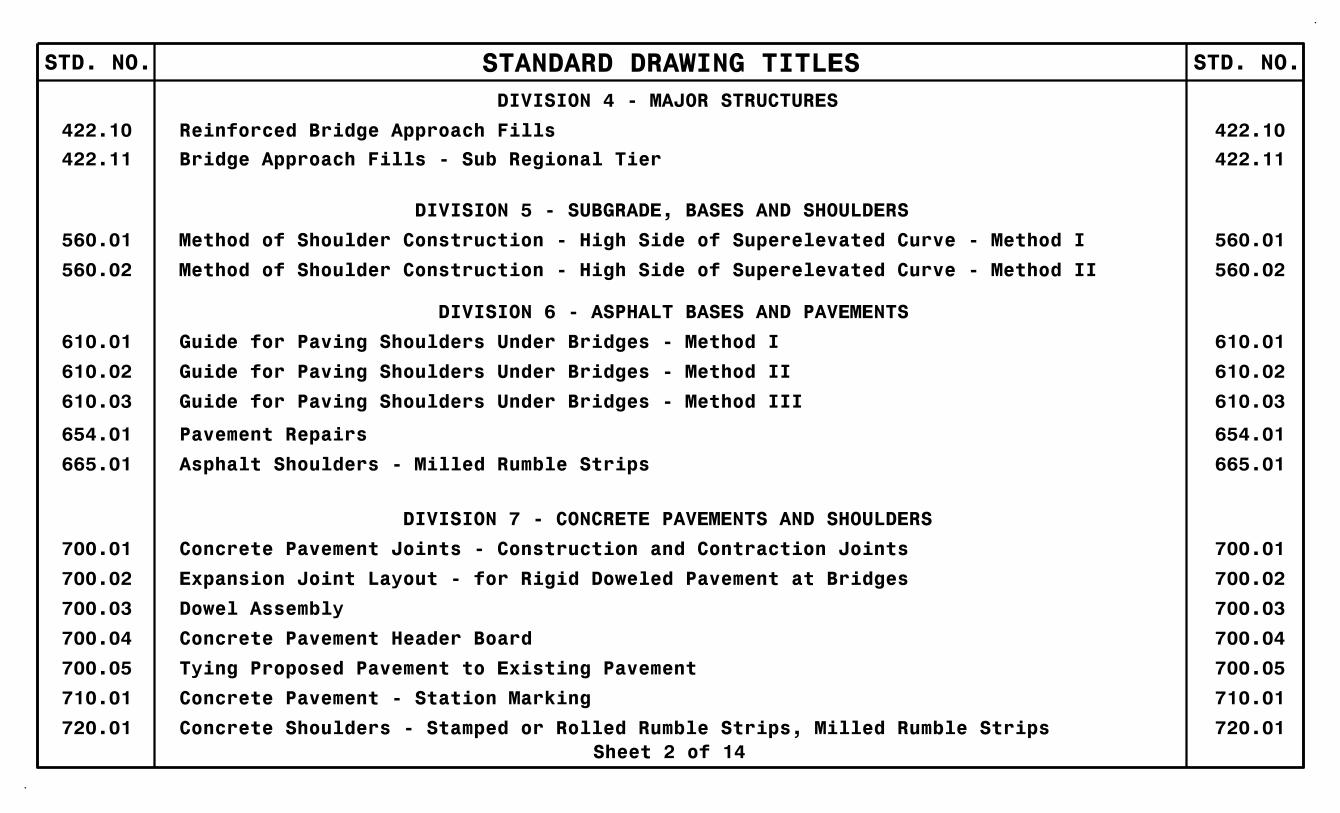
422.11 Bridge Approach Fills - Sub Regional Tier 422.11
Sheet 2 of 14
DIVISION 4 - MAJOR STRUCTURES
422.10 Reinforced Bridge Approach Fills 422.10
DIVISION 5 - SUBGRADE, BASES AND SHOULDERS
560.01 Method of Shoulder Construction - High Side of Superelevated Curve - Method I 560.01
560.02 Method of Shoulder Construction - High Side of Superelevated Curve - Method II 560.02
DIVISION 6 - ASPHALT BASES AND PAVEMENTS
610.01 Guide for Paving Shoulders Under Bridges - Method I 610.01
610.02 Guide for Paving Shoulders Under Bridges - Method II 610.02
610.03 Guide for Paving Shoulders Under Bridges - Method III 610.03
654.01 Pavement Repairs 654.01
665.01 Asphalt Shoulders - Milled Rumble Strips 665.01
DIVISION 7 - CONCRETE PAVEMENTS AND SHOULDERS
700.01 Concrete Pavement Joints - Construction and Contraction Joints 700.01
700.02 Expansion Joint Layout - for Rigid Doweled Pavement at Bridges 700.02
700.03 Dowel Assembly 700.03
700.04 Concrete Pavement Header Board 700.04
700.05 Tying Proposed Pavement to Existing Pavement 700.05
710.01 Concrete Pavement - Station Marking 710.01
720.01 Concrete Shoulders - Stamped or Rolled Rumble Strips, Milled Rumble Strips 720.01

STANDARD DRAWING TITLESSTD. NO. STD. NO.
806.03 Concrete Control-of-Access Marker 806.03
815.02 Subsurface Drain 815.02
Sheet 3 of 14
DIVISION 8 - INCIDENTALS
806.01 Concrete Right-of-Way Marker 806.01
806.02 Granite Right-of-Way Marker 806.02
815.03 Pipe Underdrain and Blind Drain 815.03
816.01 Concrete Pads - for Shoulder Drain Installation 816.01
816.02 Aggregate Shoulder Drain 816.02
816.03 Geocomposite Shoulder Drain 816.03
816.04 Markers for Drainage Structure and Concrete Pad 816.04
820.01 Funnel and Funnel Drain - 12" Metal Funnel 820.01
838.01 Concrete Endwall for Single and Double Pipe Culverts - 15" thru 48" Pipe 90° Skew 838.01
838.02 Concrete Endwall and Sluice Gate - 15" thru 36" Pipe 90° Skew 838.02
838.04 Conc. Endwall for Single & Double Pipe Culverts - 17"x13" thru 71"x47" Arch 90° Skew 838.04
838.05 Concrete ‘L’ Endwall for Single Pipe Culverts - 15" thru 48" Pipe 838.05
838.06 Concrete ‘L’ Endwall for Single Pipe Culverts - 17"x13" thru 71"x47" Pipe Arch 838.06
838.07 Conc. Endwall for Single & Double Pipe Culvrts - 40"x31" thru 66"x51" Arch 90° Skew 838.07
838.08 Concrete ‘L’ Endwall for Single Pipe Culverts - 40"x31" thru 66"x51" Pipe Arch 838.08
838.10 Concrete Endwall for Outfall - 4", 6" or 8" Pipe 838.10
838.11 Brick Endwall for Single and Double Pipe Culverts - 15" thru 48" Pipe 90° Skew 838.11
838.14 Brick Endwall for Single & Double Pipe Culverts - 17"x13" thru 71"x47" Arch 90° Skew 838.14

STANDARD DRAWING TITLESSTD. NO. STD. NO.
Sheet 4 of 14
838.15 Brick ‘L’ Endwall for Single Pipe Culverts - 15" thru 48" Pipe 838.15
838.16 Brick ‘L’ Endwall for Single Pipe Culverts - 17"x13" thru 71"x47" Pipe Arch 838.16
838.17 Brick Endwall for Single & Double Pipe Culverts - 40"x31" thru 66"x51" Arch 90° Skew 838.17
838.18 Brick Endwall for Single Pipe Culverts - 40"x31" thru 66"x51" Pipe Arch 838.18
838.20 Brick Endwall for Outfall - 4", 6" or 8" Pipe 838.20
838.21 Reinforced Concrete Endwall - for Single 54" Pipe 90° Skew 838.21
838.22 Reinforced Concrete Endwall - for Double and Triple 54" Pipes 90° Skew 838.22
838.27 Reinforced Concrete Endwall - for Single 60" Pipe 90° Skew 838.27
838.28 Reinforced Concrete Endwall - for Double and Triple 60" Pipes 90° Skew 838.28
838.33 Reinforced Concrete Endwall - for Single 66" Pipe 90° Skew 838.33
838.34 Reinforced Concrete Endwall - for Double and Triple 66" Pipes 90° Skew 838.34
838.39 Reinforced Concrete Endwall - for Single 72" Pipe 90° Skew 838.39
838.40 Reinforced Concrete Endwall - for Double and Triple 72" Pipes 90° Skew 838.40
838.45 Notes for Reinforced Concrete Endwall - Std. Dwg.s 838.21 thru 838.40 838.45
838.51 Reinforced Brick Endwall - for Single 54" Pipe 90° Skew 838.51
838.52 Reinforced Brick Endwall - for Double and Triple 54" Pipes 90° Skew 838.52
838.57 Reinforced Brick Endwall - for Single 60" Pipe 90° Skew 838.57
838.58 Reinforced Brick Endwall - for Double and Triple 60" Pipes 90° Skew 838.58
838.63 Reinforced Brick Endwall - for Single 66" Pipe 90° Skew 838.63
838.64 Reinforced Brick Endwall - for Double and Triple 66" Pipes 90° Skew 838.64

STANDARD DRAWING TITLESSTD. NO. STD. NO.
840.25 Anchorage for Frames - Brick, Concrete or Precast 840.25
Sheet 5 of 14
838.69 Reinforced Brick Endwall - for Single 72" Pipe 90° Skew 838.69
838.70 Reinforced Brick Endwall - for Double and Triple 72" Pipes 90° Skew 838.70
838.75 Notes for Reinforced Brick Endwall - Std. Dwg.s 838.51 thru 838.70 838.75
838.80 Precast Endwalls - 12" thru 72" Pipe 90° Skew 838.80
840.00 Concrete Base Pad for Drainage Structures 840.00
840.01 Brick Catch Basin - 12" thru 54" Pipe 840.01
840.02 Concrete Catch Basin - 12" thru 54" Pipe 840.02
840.03 Frame, Grates and Hood - for Use on Standard Catch Basin 840.03
840.04 Concrete Open Throat Catch Basin - 12" thru 48" Pipe 840.04
840.05 Brick Open Throat Catch Basin - 12" thru 48" Pipe 840.05
840.13 Concrete Bridge Approach Drop Inlet - 12" thru 24" Pipe 840.13
840.14 Concrete Drop Inlet - 12" thru 30" Pipe 840.14
840.15 Brick Drop Inlet - 12" thru 30" Pipe 840.15
840.16 Drop Inlet Frame and Grates - for use with Std. Dwg.s 840.14 and 840.15 840.16
840.17 Concrete Grated Drop Inlet Type ‘A’ - 12" thru 72" Pipe 840.17
840.18 Concrete Grated Drop Inlet Type ‘B’ - 12" thru 36" Pipe 840.18
840.19 Concrete Grated Drop Inlet Type ‘D’ - 12" thru 36" Pipe 840.19
840.20 Frames and Wide Slot Flat Grates 840.20
840.22 Frames and Wide Slot Sag Grates 840.22
840.24 Frames and Narrow Slot Sag Grates 840.24

STANDARD DRAWING TITLESSTD. NO. STD. NO.
Sheet 6 of 14
840.26 Brick Grated Drop Inlet Type ‘A’ - 12" thru 72" Pipe 840.26
840.27 Brick Grated Drop Inlet Type ‘B’ - 12" thru 36" Pipe 840.27
840.28 Brick Grated Drop Inlet Type ‘D’ - 12" thru 36" Pipe 840.28
840.29 Frames and Narrow Slot Flat Grates 840.29
840.30 Driveway Drop Inlet 840.30
840.31 Concrete Junction Box - 12" thru 66" Pipe 840.31
840.32 Brick Junction Box - 12" thru 66" Pipe 840.32
840.33 Angled Vane Grates and Frames 840.33
840.34 Traffic Bearing Junction Box - for Use with Pipes 42" and Under 840.34
840.35 Traffic Bearing Grated Drop Inlet - for Cast Iron Double Frame and Grates 840.35
840.36 Traffic Bearing Grated Drop Inlet - for Steel (840.37) Double Frame and Grates 840.36
840.37 Steel Grate and Frame 840.37
840.41 Spring Box - Concrete or Brick 840.41
840.45 Precast Drainage Structure 840.45
840.46 Traffic Bearing Precast Drainage Structure 840.46
840.51 Brick Manhole - 12" thru 36" Pipe 840.51
840.53 Precast Manhole with Masonry Base - 12" thru 42" Pipe 840.53
840.54 Manhole Frame and Cover 840.54
840.66 Drainage Structure Steps 840.66
840.71 Concrete and Brick Pipe Plug 840.71
840.72 Pipe Collar 840.72
STANDARD DRAWING TITLESSTD. NO. STD. NO.
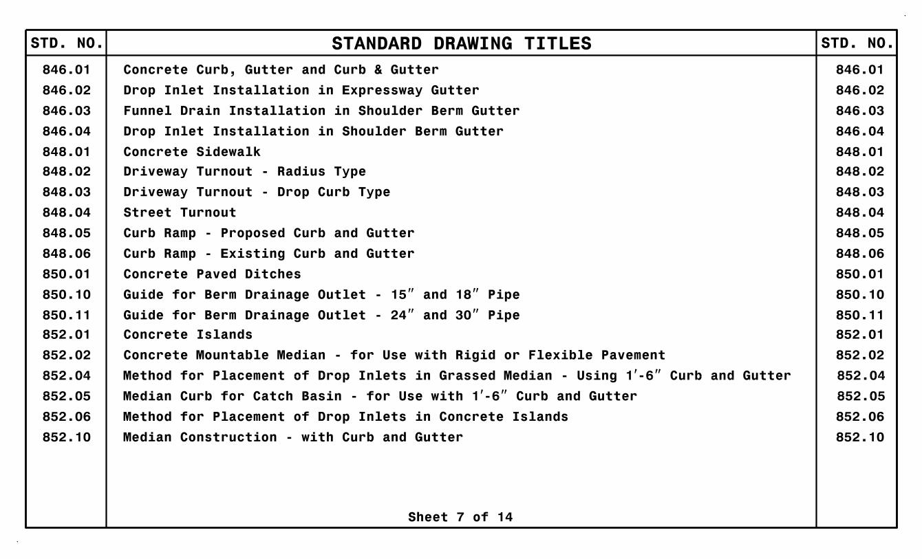
848.05 Curb Ramp - Proposed Curb and Gutter 848.05
850.01 Concrete Paved Ditches 850.01
848.06 Curb Ramp - Existing Curb and Gutter 848.06
Sheet 7 of 14
846.01 Concrete Curb, Gutter and Curb & Gutter 846.01
846.02 Drop Inlet Installation in Expressway Gutter 846.02
846.03 Funnel Drain Installation in Shoulder Berm Gutter 846.03
846.04 Drop Inlet Installation in Shoulder Berm Gutter 846.04
848.01 Concrete Sidewalk 848.01
848.02 Driveway Turnout - Radius Type 848.02
848.03 Driveway Turnout - Drop Curb Type 848.03
848.04 Street Turnout 848.04
850.10 Guide for Berm Drainage Outlet - 15" and 18" Pipe 850.10
850.11 Guide for Berm Drainage Outlet - 24" and 30" Pipe 850.11
852.01 Concrete Islands 852.01
852.02 Concrete Mountable Median - for Use with Rigid or Flexible Pavement 852.02
852.06 Method for Placement of Drop Inlets in Concrete Islands 852.06
852.10 Median Construction - with Curb and Gutter 852.10

STANDARD DRAWING TITLESSTD. NO. STD. NO.
Sheet 8 of 14
854.01 Double Faced Concrete Barrier - Types I, II, III and IV 854.01
854.02 Double Faced Concrete Barrier - Types ‘T’, ‘T1’ and ‘T2’ 854.02
854.04 Concrete Median Barrier - Precast Permanent 854.04
854.05 Concrete Median Transition Barrier - Location of Overhead Assembly 854.05
857.01 Precast Reinforced Concrete Barrier - 41" Single Faced 857.01
862.01 Guardrail Placement 862.01
862.02 Guardrail Installation 862.02
862.03 Structure Anchor Units 862.03
862.04 Anchoring End of Guardrail - B-77 and B-83 Anchor Units 862.04
865.01 Cable Guiderail 865.01
866.02 Woven Wire Fence - with Wood Post 866.02
866.03 Woven Wire Fence - with Steel Post 866.03
866.04 Barbed Wire Fence - with Wood Posts (2 - 7 Strands) 866.04
866.05 Glare Screen - Chain Link Fabric/Guardrail Mounted 866.05
876.01 Rip Rap in Channels 876.01
876.02 Guide for Rip Rap at Pipe Outlets 876.02
876.03 Drainage Ditches with Class ‘A’ Rip Rap 876.03
876.04 Drainage Ditches with Class ‘B’ Rip Rap 876.04

STANDARD DRAWING TITLESSTD. NO. STD. NO.
Sheet 9 of 14
DIVISION 9 - SIGNING
901.10 Type ‘A’ Signs - Welded Stud Construction 901.10
901.20 Type ‘B’ Signs - Welded Stud Construction 901.20
901.50 Arrows and Shields 901.50
901.60 Rivet Spacing for Overlayed Signs 901.60
901.70 Sign Stringers and Support Spacing 901.70
901.80 Sign Mounting Details - Type ’A’ and ’B’ Signs 901.80
903.10 Ground Mounted Sign Supports 903.10
903.20 Wood Sign Post 903.20
903.30 Barrier Sign Support Assembly 903.30
903.40 Median Barrier Sign Support and Anchorage 903.40
904.10 Orientation of Ground Mounted Signs 904.10
904.20 Secondary Sign Mounting 904.20
904.30 Supplemental Sign Mounting 904.30
904.40 Milepost and Placement 904.40
904.50 Mounting of Type ‘D’, ‘E’ and ‘F’ Signs on ‘U’ Channel Posts 904.50
STANDARD DRAWING TITLESSTD. NO. STD. NO.
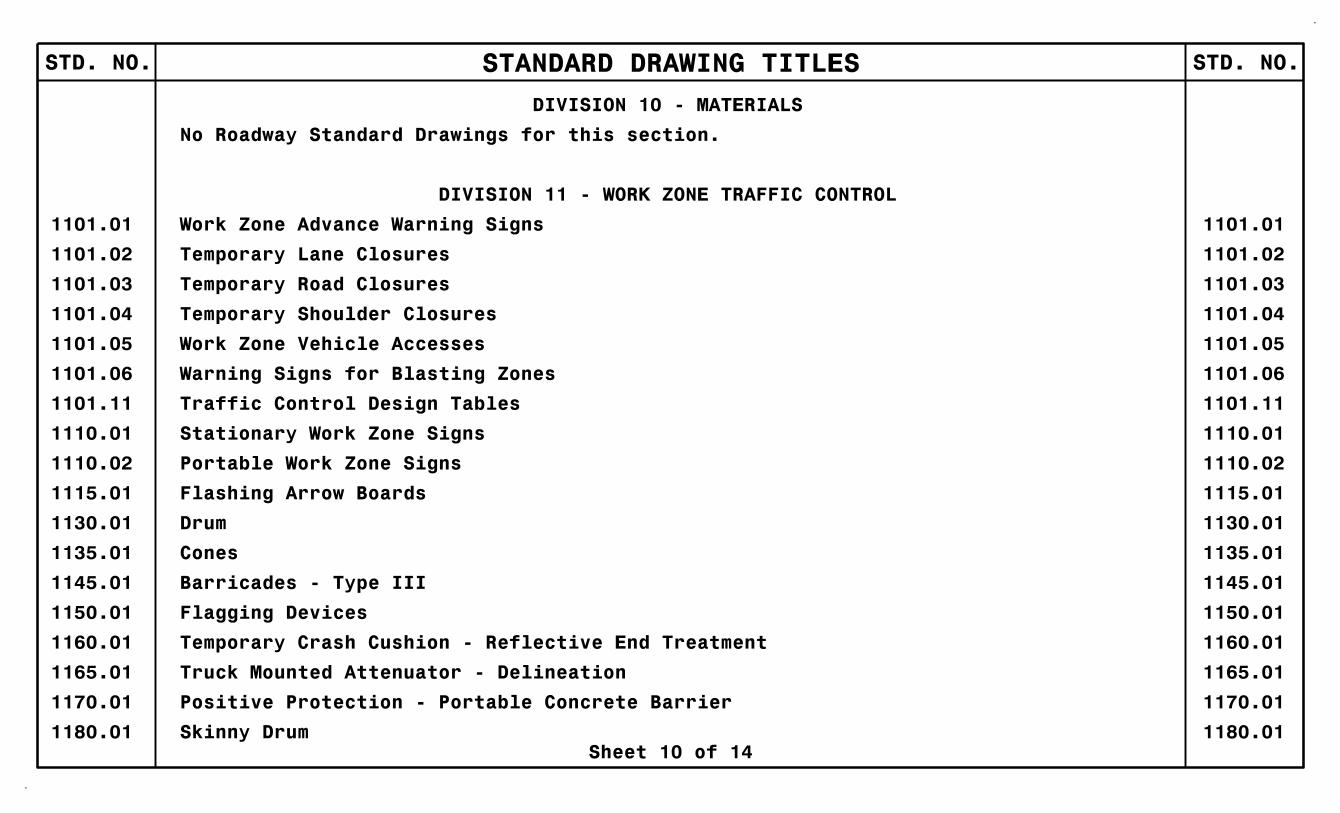
DIVISION 10 - MATERIALS
No Roadway Standard Drawings for this section.
DIVISION 11 - WORK ZONE TRAFFIC CONTROL
1101.01 Work Zone Advance Warning Signs 1101.01
1101.02 Temporary Lane Closures 1101.02
1101.03 Temporary Road Closures 1101.03
1101.04 Temporary Shoulder Closures 1101.04
1101.05 Work Zone Vehicle Accesses 1101.05
1101.06 Warning Signs for Blasting Zones 1101.06
1101.11 Traffic Control Design Tables 1101.11
1130.01 Drum 1130.01
1135.01 Cones 1135.01
1145.01 Barricades - Type III 1145.01
1150.01 Flagging Devices 1150.01
1160.01 Temporary Crash Cushion - Reflective End Treatment 1160.01
1110.01 Stationary Work Zone Signs 1110.01
1110.02 Portable Work Zone Signs 1110.02
1115.01 Flashing Arrow Boards 1115.01
1165.01 Truck Mounted Attenuator - Delineation 1165.01
Sheet 10 of 14
1180.01 Skinny Drum 1180.01
1170.01 Positive Protection - Portable Concrete Barrier 1170.01

STANDARD DRAWING TITLESSTD. NO. STD. NO.
1205.13 Pavement Markings - New Interchanges and Intersections 1205.13
Sheet 11 of 14
DIVISION 12 - PAVEMENT MARKINGS, MARKERS AND DELINEATION
1205.01 Pavement Markings - Line Types and Offsets 1205.01
1205.02 Pavement Markings - Divided and Undivided Roadways 1205.02
1205.03 Pavement Markings - Interchanges 1205.03
1205.04 Pavement Markings - Intersections 1205.04
1205.05 Pavement Markings - Turn Lanes 1205.05
1205.06 Pavement Markings - Thru Lane Drops 1205.06
1205.07 Pavement Markings - Pedestrian Crosswalks 1205.07
1205.08 Pavement Markings - Symbols and Word Messages 1205.08
1205.09 Pavement Markings - Painted Islands 1205.09
1205.10 Pavement Markings - School Areas 1205.10
1205.11 Pavement Markings - Railroad Crossings 1205.11
1205.12 Pavement Markings - Bridges 1205.12
1250.01 Pavement Marker Spacing 1250.01
1251.01 Raised Pavement Markers - Permanent and Temporary 1251.01
1253.01 Snowplowable Raised Pavement Markers 1253.01
1261.01 Guardrail and Barrier Delineator Spacing 1261.01
1261.02 Guardrail and Barrier Delineator Types 1261.02
1262.01 Guardrail End Delineation 1262.01
1264.01 Object Markers 1264.01
1264.02 Placement of Object Markers 1264.02

STANDARD DRAWING TITLESSTD. NO. STD. NO.
1515.01 Water Meter 1515.01
1515.02 Fire Hydrant 1515.02
1520.01 Sewer Clean Out 1520.01
1525.06 Precast Sanitary Sewer Manholes - with Cast in Place Bottom 1525.06
Sheet 12 of 14
1267.01 Flexible Delineator Installation 1267.01
1267.02 Flexible Delineator Spacing 1267.02
1267.03 Flexible Delineator - Interchanges 1267.03
DIVISION 14 - LIGHTING
1401.01 High Mount Standard 1401.01
1402.01 High Mount Foundation 1402.01
1403.01 High Mount Luminaires 1403.01
1404.01 Light Standards 1404.01
1405.01 Standard Foundation 1405.01
1406.01 Light Standard Luminaires 1406.01
1407.01 Electric Service Pole and Lateral 1407.01
1408.01 Light Control System 1408.01
1409.01 Electrical Duct 1409.01
1410.01 Feeder Circuits 1410.01
1411.01 Electrical Junction Boxes 1411.01
1412.01 Underpass Lighting 1412.01
DIVISION 15 - UTILITIES

STANDARD DRAWING TITLESSTD. NO. STD. NO.
1631.01 Matting Installation 1631.01
1633.01 Temporary Rock Silt Check Type A 1633.01
1630.04 Stilling Basin For Pumped Effluent 1630.04
1630.02 Silt Basin Type B 1630.02
1632.01 Rock Inlet Sediment Trap Type A 1632.01
1632.02 Rock Inlet Sediment Trap Type B 1632.02
1632.03 Rock Inlet Sediment Trap Type C 1632.03
1634.01 Temporary Rock Sediment Dam Type A 1634.01
1634.02 Temporary Rock Sediment Dam Type B 1634.02
1635.01 Rock Pipe Inlet Sediment Trap Type A 1635.01
1633.02 Temporary Rock Silt Check Type B 1633.02
Sheet 13 of 14
DIVISION 16 - EROSION CONTROL AND ROADSIDE DEVELOPMENT
1604.01 Railroad Erosion Control 1604.01
1605.01 Temporary Silt Fence 1605.01
1606.01 Special Sediment Control Fence 1606.01
1607.01 Gravel Construction Entrance 1607.01
1622.01 Guide for Temporary Berms and Slope Drains 1622.01
1630.01 Riser Basin 1630.01
1630.03 Temporary Silt Ditch 1630.03
1630.05 Temporary Diversion 1630.05
1630.06 Special Stilling Basin 1630.06

STANDARD DRAWING TITLESSTD. NO. STD. NO.
1640.01 Coir Fiber Baffle 1640.01
1635.02 Rock Pipe Inlet Sediment Trap Type B 1635.02
1645.01 Temporary Stream Crossing 1645.01
1705.03 Signal Heads - Wire Color Conventions 1705.03
1743.01 Pedestal 1743.01
1736.01 Spread Spectrum Radio 1736.01
1751.02 Controllers and Cabinets - Power, Ground and Auxiliary 1752.02
Sheet 14 of 14
DIVISION 17 - Signals and Traffic Management Systems
1700.01 Electrical Service Options 1700.01
1700.02 Electrical Service Grounding 1700.02
1705.01 Signal Heads - Vehicular Signal Heads 1705.01
1705.02 Signal Heads - Pedestrian Assemblies 1705.02
1715.01 Underground Conduit - Trenching 1715.01
1716.01 Junction Boxes 1716.01
1720.01 Wood Poles 1720.01
1721.01 Guy Assemblies 1721.01
1725.01 Inductive Detection Loops 1725.01
1730.01 Fiber-Optic Cable - Spare Cable Storage 1730.01
1751.01 Controllers and Cabinets - Cabinet Component Layout 1751.01