standard details - glosfordsips.co.uk · gts gd 05 a 04/12/17 party wall/floor detail in different...
TRANSCRIPT
Glosford Timber Solutions Ltd.
Homer Road
Hereford
HR4 9BP
01432 842999
www.glosfordsips.co.uk
Standard Details
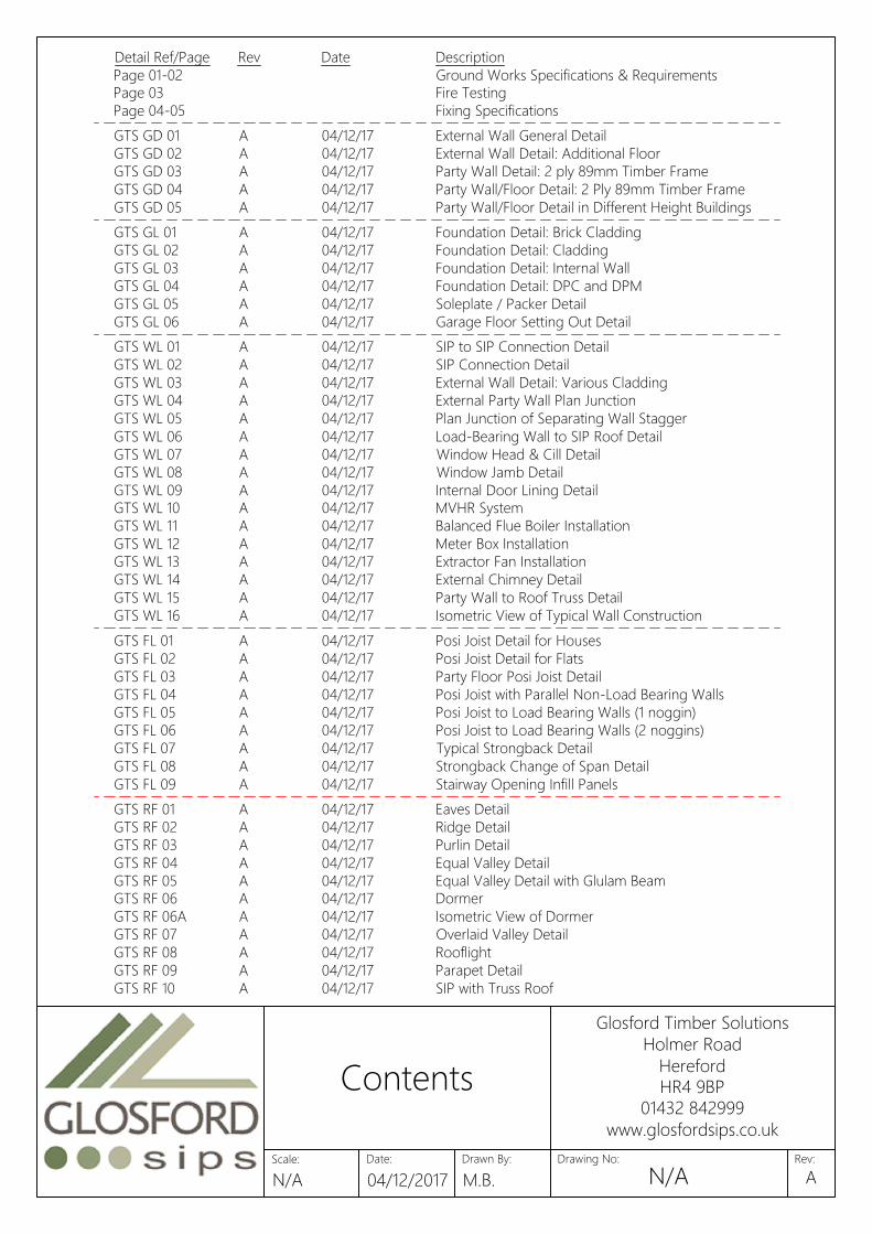
GTS FL 01 A 04/12/17 Posi Joist Detail for Houses
GTS FL 02 A 04/12/17 Posi Joist Detail for Flats
GTS FL 03 A 04/12/17 Party Floor Posi Joist Detail
GTS FL 04 A 04/12/17 Posi Joist with Parallel Non-Load Bearing Walls
GTS FL 05 A 04/12/17 Posi Joist to Load Bearing Walls (1 noggin)
GTS FL 06 A 04/12/17 Posi Joist to Load Bearing Walls (2 noggins)
GTS FL 07 A 04/12/17 Typical Strongback Detail
GTS FL 08 A 04/12/17 Strongback Change of Span Detail
GTS FL 09 A 04/12/17 Stairway Opening Infill Panels
GTS WL 01 A 04/12/17 SIP to SIP Connection Detail
GTS WL 02 A 04/12/17 SIP Connection Detail
GTS WL 03 A 04/12/17 External Wall Detail: Various Cladding
GTS WL 04 A 04/12/17 External Party Wall Plan Junction
GTS WL 05 A 04/12/17 Plan Junction of Separating Wall Stagger
GTS WL 06 A 04/12/17 Load-Bearing Wall to SIP Roof Detail
GTS WL 07 A 04/12/17 Window Head & Cill Detail
GTS WL 08 A 04/12/17 Window Jamb Detail
GTS WL 09 A 04/12/17 Internal Door Lining Detail
GTS WL 10 A 04/12/17 MVHR System
GTS WL 11 A 04/12/17 Balanced Flue Boiler Installation
GTS WL 12 A 04/12/17 Meter Box Installation
GTS WL 13 A 04/12/17 Extractor Fan Installation
GTS WL 14 A 04/12/17 External Chimney Detail
GTS WL 15 A 04/12/17 Party Wall to Roof Truss Detail
GTS WL 16 A 04/12/17 Isometric View of Typical Wall Construction
GTS GL 01 A 04/12/17 Foundation Detail: Brick Cladding
GTS GL 02 A 04/12/17 Foundation Detail: Cladding
GTS GL 03 A 04/12/17 Foundation Detail: Internal Wall
GTS GL 04 A 04/12/17 Foundation Detail: DPC and DPM
GTS GL 05 A 04/12/17 Soleplate / Packer Detail
GTS GL 06 A 04/12/17 Garage Floor Setting Out Detail
GTS GD 01 A 04/12/17 External Wall General Detail
GTS GD 02 A 04/12/17 External Wall Detail: Additional Floor
GTS GD 03 A 04/12/17 Party Wall Detail: 2 ply 89mm Timber Frame
GTS GD 04 A 04/12/17 Party Wall/Floor Detail: 2 Ply 89mm Timber Frame
GTS GD 05 A 04/12/17 Party Wall/Floor Detail in Different Height Buildings
Detail Ref/Page Rev Date Description
Page 01-02 Ground Works Specifications & Requirements
Page 03 Fire Testing
Page 04-05 Fixing Specifications
GTS RF 01 A 04/12/17 Eaves Detail
GTS RF 02 A 04/12/17 Ridge Detail
GTS RF 03 A 04/12/17 Purlin Detail
GTS RF 04 A 04/12/17 Equal Valley Detail
GTS RF 05 A 04/12/17 Equal Valley Detail with Glulam Beam
GTS RF 06 A 04/12/17 Dormer
GTS RF 06A A 04/12/17 Isometric View of Dormer
GTS RF 07 A 04/12/17 Overlaid Valley Detail
GTS RF 08 A 04/12/17 Rooflight
GTS RF 09 A 04/12/17 Parapet Detail
GTS RF 10 A 04/12/17 SIP with Truss Roof
Date:
Glosford Timber Solutions
Holmer Road
Hereford
HR4 9BP
01432 842999
www.glosfordsips.co.uk
Scale: Drawn By: Drawing No: Rev:
Contents
N/A 04/12/2017 M.B.N/A A
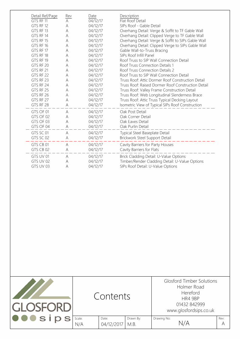
GTS OF 01 A 04/12/17 Oak Post Detail
GTS OF 02 A 04/12/17 Oak Corner Detail
GTS OF 03 A 04/12/17 Oak Eaves Detail
GTS OF 04 A 04/12/17 Oak Purlin Detail
GTS UV 01 A 04/12/17 Brick Cladding Detail: U-Value Options
GTS UV 02 A 04/12/17 Timber/Render Cladding Detail: U-Value Options
GTS UV 03 A 04/12/17 SIPs Roof Detail: U-Value Options
GTS CB 01 A 04/12/17 Cavity Barriers for Party Houses
GTS CB 02 A 04/12/17 Cavity Barriers for Flats
GTS SC 01 A 04/12/17 Typical Steel Baseplate Detail
GTS SC 02 A 04/12/17 Brickwork Steel Support Detail
Detail Ref/Page Rev Date Description
GTS RF 11 A 04/12/17 Flat Roof Detail
GTS RF 12 A 04/12/17 SIPs Roof - Gable Detail
GTS RF 13 A 04/12/17 Overhang Detail: Verge & Soffit to TF Gable Wall
GTS RF 14 A 04/12/17 Overhang Detail: Clipped Verge to TF Gable Wall
GTS RF 15 A 04/12/17 Overhang Detail: Verge & Soffit to SIPs Gable Wall
GTS RF 16 A 04/12/17 Overhang Detail: Clipped Verge to SIPs Gable Wall
GTS RF 17 A 04/12/17 Gable Wall-to-Truss Bracing
GTS RF 18 A 04/12/17 SIPs Roof Infill Panel
GTS RF 19 A 04/12/17 Roof Truss to SIP Wall Connection Detail
GTS RF 20 A 04/12/17 Roof Truss Connection Details 1
GTS RF 21 A 04/12/17 Roof Truss Connection Details 2
GTS RF 22 A 04/12/17 Roof Truss to SIP Wall Connection Detail
GTS RF 23 A 04/12/17 Truss Roof: Attic Dormer Roof Construction Detail
GTS RF 24 A 04/12/17 Truss Roof: Raised Dormer Roof Construction Detail
GTS RF 25 A 04/12/17 Truss Roof: Valley Frame Construction Detail
GTS RF 26 A 04/12/17 Truss Roof: Web Longitudinal Slenderness Brace
GTS RF 27 A 04/12/17 Truss Roof: Attic Truss Typical Decking Layout
GTS RF 28 A 04/12/17 Isometric View of Typical SIPs Roof Construction
Date:
Glosford Timber Solutions
Holmer Road
Hereford
HR4 9BP
01432 842999
www.glosfordsips.co.uk
Scale: Drawn By: Drawing No: Rev:
Contents
N/A 04/12/2017 M.B.N/A A

Kingspan Insulation
Technical Advisory -EN 1365-1 Testing on Kingspan TEK
TEK DOCUMENT NUMBER 001 JAN 2016
This Document covers the EN 1365-1 testing for the Kingspan TEK panel.
TECHNICAL NOTE
· Kingspan Insulation Limited have moved All of the Fire resistance testing that we undertake to the EN methods to fit
with the European norm. The EN test methods are considered to be slightly more severe than the BS methods/ BS 476
parts 20, 21 and 22.
· The build-up tested was a:
15mm fire resistant plasterboard fixed to a 25mm timber batten-onto the 142mm TEK panel. The construction achieved
77minutes insulation and integrity. Report number 345653.
· Exova have confirmed the following through Assessment:
Internal Lining TEK Panel Fire resistance in minutes
9.5mm regular Plasterboard* 142 or 172mm 30 mins
1x 12.5mm Fire resistant PB 142 or 172mm 60 mins
1x 15mm Fire resistant PB 142 or 172mm 77 mins (test result)
2x 12.5mm Fire resistant PB 142 or 172mm 90 mins
1x 12.5mm Magnesium Oxide 142 or 172mm 120 mins minimum (product board
or similar can be fitted to the outside should
the fire resistant level be required
in both directions)
*Other internal finishes can be used please discuss with Kingspan Insulation Ltd
FURTHER DETAILS
· We trust the foregoing technical note is of assistance. Please do not hesitate to contact us in the event of any
further queries.
Tel: +44 (0) 1544 387 382
Fax: +44 (0) 1544 387 482
Email: [email protected]
Date:
Glosford Timber Solutions
Holmer Road
Hereford
HR4 9BP
01432 842999
www.glosfordsips.co.uk
Scale: Drawn By: Drawing No: Rev:
EN 1365-1 Testing
on Kingspan
N/A 04/12/2017 M.B.N/A A

Application Fastener Type Spacing
Fixing soleplate Specifications should be in accordance with project
structural engineers' recommendations based upon
geography and project foundation substructure
Fixing soleplate or combined soleplate
and bottomplate
Panel straps to substructure/foundations Specifications should be in accordance with project
structural engineers' recommendations based upon
geography and project foundation substructure
As per project structural engineers'
recommendations
Fixing bottomplates to soleplates 3.1mm x 90 mm galvanized ring-shank nails 200mm centres in two staggered rows
Fixing 15mm x 100 OSB3 splines into Kingspan
TEK Building System panels
3.1mm x 63mm galvanized ring-shank nails 50mm centres both sides of the panels
Fixing bottomplates, headplates, end timbers
and edge timbers into Kingspan TEK Building
System panels
3.1mm x 63mm galvanized ring-shank nails 50mm centres both sides of the panels
Fixing 100mm x 110 / 140mm insulated splines or
timber posts into Kingspan TEK Building System
panels
3.1mm x 63mm galvanized ring-shank nails 50mm centres both sides of the panels
Fixing 100mm x 150mm bevelled headplate to
Kingspan TEK Building System panels
3.1mm x 63mm galvanized ring-shank nails 50mm centres both sides of the panels
Fixing Kingspan TEK Building System wall panels
at corner joints
Rothoblaas TBS 8mm Ø SIP screws or similar, 50mm
embedment
Typically at 400mm c/c, unless engineer
specifies otherwise
Fixing Kingspan TEK Building System roof
sections at wall/floor junctions, ridge beams,
intermediate purlins and gable walls
Rothoblaas TBS 8mm Ø SIP screws or similar, 50mm
embedment
Typically at 200mm c/c, unless engineer
specifies otherwise
Fixing joist hangers to headplate or laminated
beams (fixings may vary depending on
specification of joist hanger - please refer to
manufacturers' instructions floor systems)
3.75mm x 32mm square twist shank nails or Simpson N10
nails
Into side and top of headplate locations
marked out
Fixing I-beams/joist to joist hanger (fasteners
may vary depending on specification of joist
hanger - please refer to manufacturers'
instructions floor system)
3.75mm x 32mm square twist shank nails or Simpson N10
nails
In pre-drilled holes for bottom flange
Fixing OSB3/P5 floor decking to joists/headplate
or header joist
3.1mm x 63mm galvanized ring-shank nails Maximum 200mm centres
Fixing rim board to headplate Skew nail 3.75mm x 75mm round wire nails 150mm
Fixing OSB3/P5 floor decking to joists/rimboard 3.35mm x 65mm round wire nails 200mm
Fixing brickwork cavity wall ties to Kingspan TEK
Building System wall panels
Simpson Strong Tie SWT50 wall ties fixed to SIP panels
with stainless steel screws.
Where basic wind speed does not exceed
52m/s: 4.4 ties per m²
If exceeds: 7 ties per m²
Fixing treated timber counter battens to
Kingspan TEK Building System wall/roof panels
for ventilation
ABC Spax 5mm x 60mm or EJOT M5 70mm stainless steel
screws or equivalent (to penetrate through 15mm OSB/3
face)
Typically 300mm centres. For further
guidance follow project structural
engineers' recommendations
Fixing Timber Frame to Soleplate 3.1mm x 63mm galvanized ring-shank nails 200mm centres in two staggered rows
Fixing Timber Frame Panels to SIPs Rothoblaas TBS 8mm Ø SIP screws or similar Typically at 400mm c/c, unless engineer
specifies otherwise
Fixing Non-Load Bearing Timber Frame
soleplates and headbinders to joist noggins
3.1mm x 90 mm galvanized ring-shank nails Skew fix 2no nails per noggin
Fixing Kingspan TEK Building System to oak
timber framing
Rothoblaas TBS 8mm Ø SIP screws or similar, 50mm
embedment into oak
Typically at 400mm c/c, unless engineer
specifies otherwise
Fixing Timber Frame Party Wall Panels to Glulam
Header Beam
Rothoblaas TBS 8mm Ø x 160mm SIP screws or similar Typically at 600mm c/c, unless engineer
specifies otherwise
Date:
Glosford Timber Solutions
Holmer Road
Hereford
HR4 9BP
01432 842999
www.glosfordsips.co.uk
Scale: Drawn By: Drawing No: Rev:
Fixing Specifications
N/A 04/12/2017 M.B.N/A A

G.L
150
Minimum 100mm Mineral Fibre
(10-33kg/m²) insulation to floor
zone (by others). Insulation not
shown for clarity
Plasterboard (by others)
Engineered posi floor
system with 22mm thick
weather resistant chipboard
(minimum weight 15kg/m²)
OSB Cover strip
For Window Details, see drawing
GTS WL 06 and GTS WL 07
DPM (by others)
Insulation (by others)
Brick external leaf
(by others)
Proprietary cavity
closer (by others)
Proprietary cavity
closer (by others)
DPC (by others)
For Eaves Detail see
drawing GTS RF 01
For Floor Details, see
drawing GTS FL 01, GTS
FL 02 and GTS FL 03
For Foundation Details,
see drawings GTS GL 01
to GTS GL 05
SIPs
Screed (by others)
450mm wide 2000g PVCu DPC
to underside of soleplate
For Window Details, see drawing
GTS WL 06 and GTS WL 07
Date:
Glosford Timber Solutions
Holmer Road
Hereford
HR4 9BP
01432 842999
www.glosfordsips.co.uk
Scale: Drawn By: Drawing No: Rev:
External Wall
Detail
1:20 04/12/2017 M.B. GTS GD 01A
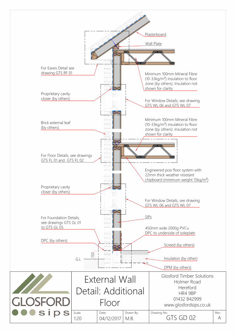
G.L
150
Plasterboard
Wall Plate
Brick external leaf
(by others)
Engineered posi floor system with
22mm thick weather resistant
chipboard (minimum weight 15kg/m²)
Proprietary cavity
closer (by others)
Proprietary cavity
closer (by others)
SIPs
DPM (by others)
DPC (by others)
Insulation (by other)
Screed (by others)
For Eaves Detail see
drawing GTS RF 01
For Floor Details, see drawings
GTS FL 01 and GTS FL 02
For Window Details, see drawing
GTS WL 06 and GTS WL 07
For Window Details, see drawing
GTS WL 06 and GTS WL 07
For Foundation Details,
see drawings GTS GL 01
to GTS GL 05
450mm wide 2000g PVCu
DPC to underside of soleplate
Minimum 100mm Mineral Fibre
(10-33kg/m²) insulation to floor
zone (by others). Insulation not
shown for clarity
Minimum 100mm Mineral Fibre
(10-33kg/m²) insulation to floor
zone (by others). Insulation not
shown for clarity
Date:
Glosford Timber Solutions
Holmer Road
Hereford
HR4 9BP
01432 842999
www.glosfordsips.co.uk
Scale: Drawn By: Drawing No: Rev:
External Wall
Detail: Additional
Floor
1:20 04/12/2017 M.B. GTS GD 02A

9mm non-combustible board (by others)
SIPs Roof
100mm 7N/mm² blocks (by others)
Party Wall Insulation required for
acoustic performance (by others)
For Floor Details, see drawings
GTS FL 02 and GTS FL 03
For Foundation Details,
see drawing GTS GL 03
Roof battens and
counter-battens (by others)
DPM (by others)
Engineered posi floor system with
22mm thick weather resistant
chipboard (minimum weight 15kg/m²)
Insulation (by other)
Screed (by others)
250
min.
To Robust Details -
www.robustdetails.com
(by others)
50mm min. cavity
between sheathing
Fully filled with Rockwool Flexi (or
similar approved) cavity insulation
For Floor Details, see drawings
GTS FL 02 and GTS FL 03
Proprietary Party wall
ties at 1200mm centres
2 Layers of Plasterboard as
per Robust Details (by others)
(www.robustdetails.com)
89mm Timber frame with 9mm
OSB sheathing (sheathing as
required by Glosford engineer)
450mm wide 2000g PVCu DPC
to underside of soleplate
Date:
Glosford Timber Solutions
Holmer Road
Hereford
HR4 9BP
01432 842999
www.glosfordsips.co.uk
Scale: Drawn By: Drawing No: Rev:
Party Wall Detail:
2 ply 89mm
Timber Frame
1:20 04/12/2017 M.B. GTS GD 03A

50mm min. cavity
between sheathing
100mm 7N/mm² block (by others)
2 Layers of Plasterboard as per
standard Robust Details (by others)
(www.robustdetails.com)
450mm wide 2000g PVCu DPC
to underside of soleplate
For Foundation Details,
see drawing GTS GL 03
For Floor Details, see
drawing GTS FL 03
DPM (by others)
To standard Robust Details
(by others)
(www.robustdetails.com)
89mm Timber frame with 9mm
OSB sheathing (sheathing as
required by Glosford engineer)
Insulation (by other)
Screed (by others)
250
min.
9mm non-combustible board (by others)
SIPs Roof
Engineered posi floor system
with 18mm thick OSB3
sub-deck (by Glosford)
Acoustic Floor System (by others)
Resilient bar (by others)
Roof battens and
counter-battens (by others)
For Floor Details, see
drawing GTS FL 03
Party Wall Insulation
required for acoustic
performance (by others)
Fully filled with Rockwool Flexi (or
similar approved) cavity insulation
Proprietary Party wall ties
at 1200mm centres
Date:
Glosford Timber Solutions
Holmer Road
Hereford
HR4 9BP
01432 842999
www.glosfordsips.co.uk
Scale: Drawn By: Drawing No: Rev:
Party Wall & Floor
Detail: 2 ply 89mm
Timber Frame
1:20 04/12/2017 M.B. GTS GD 04A
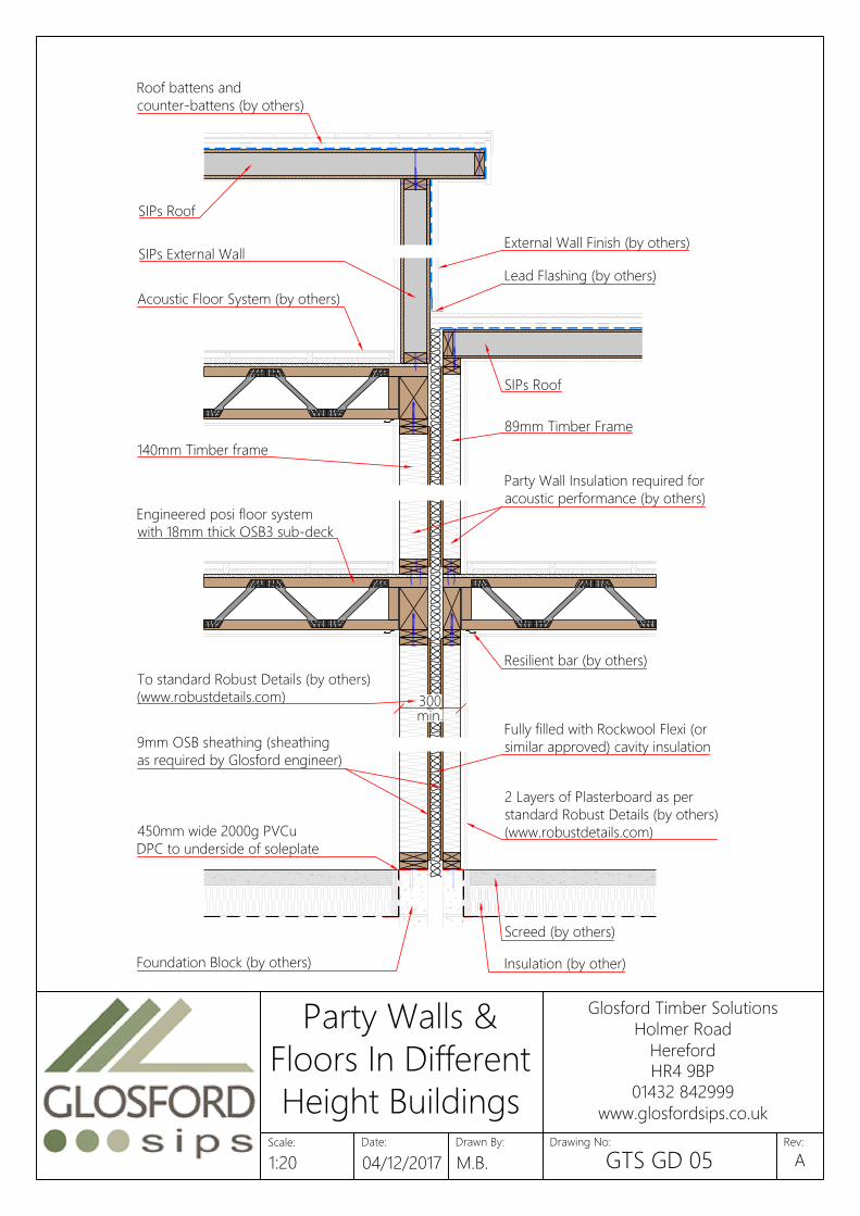
300
min.
Foundation Block (by others)
Fully filled with Rockwool Flexi (or
similar approved) cavity insulation
2 Layers of Plasterboard as per
standard Robust Details (by others)
(www.robustdetails.com)
89mm Timber Frame
SIPs Roof
Engineered posi floor system
with 18mm thick OSB3 sub-deck
Resilient bar (by others)
9mm OSB sheathing (sheathing
as required by Glosford engineer)
SIPs External Wall
External Wall Finish (by others)
450mm wide 2000g PVCu
DPC to underside of soleplate
Party Wall Insulation required for
acoustic performance (by others)
140mm Timber frame
SIPs Roof
To standard Robust Details (by others)
(www.robustdetails.com)
Lead Flashing (by others)
Acoustic Floor System (by others)
Roof battens and
counter-battens (by others)
Screed (by others)
Insulation (by other)
Date:
Glosford Timber Solutions
Holmer Road
Hereford
HR4 9BP
01432 842999
www.glosfordsips.co.uk
Scale: Drawn By: Drawing No: Rev:
Party Walls &
Floors In Different
Height Buildings
1:20 04/12/2017 M.B. GTS GD 05A

G.L
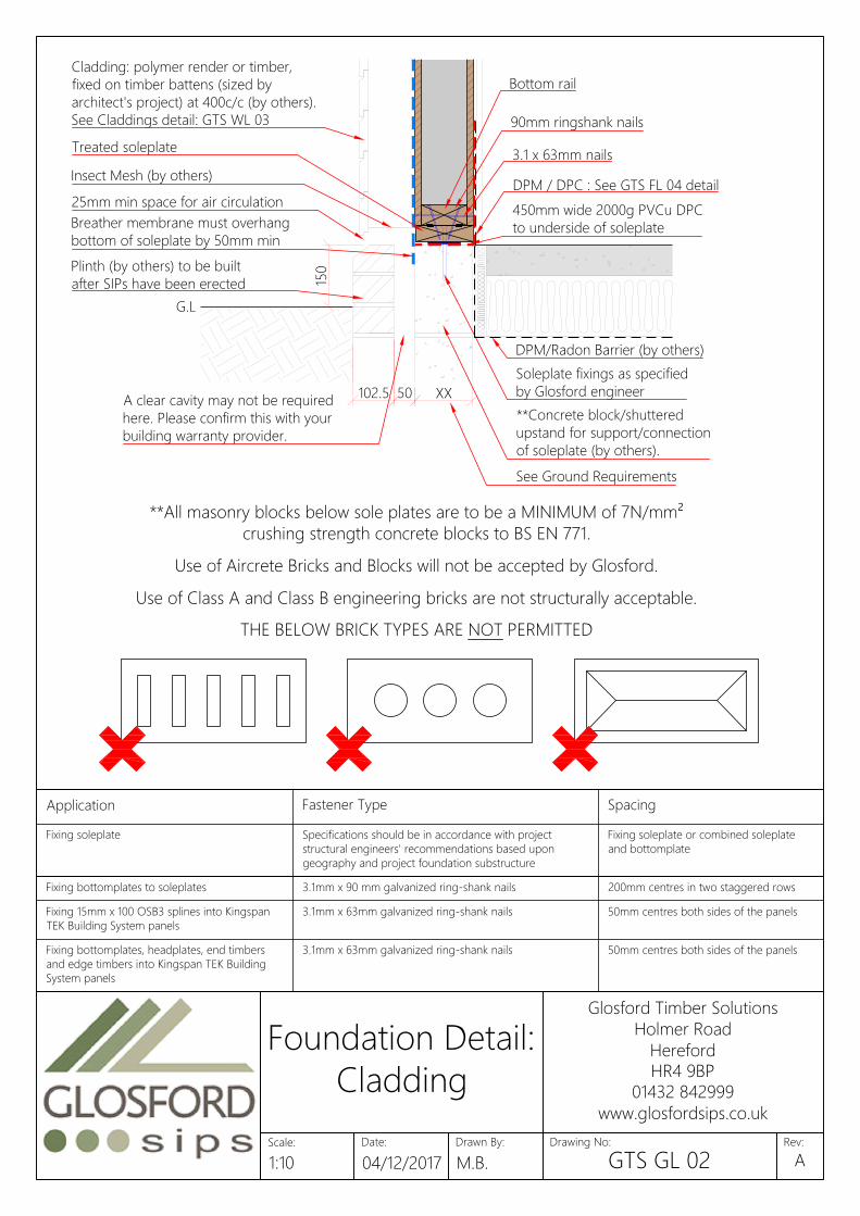
150
Brick cladding with min. 50mm
cavity (see Claddings detail: GTS
WL 03). All cladding (by others)
to be built after SIPs are erected
XX102.5
Min. Cavity 50mm
**All masonry blocks below sole plates are to be a MINIMUM of 7N/mm²
crushing strength concrete blocks to BS EN 771.
Use of Aircrete Bricks and Blocks will not be accepted by Glosford.
Use of Class A and Class B engineering bricks are not structurally acceptable.
THE BELOW BRICK TYPES ARE NOT PERMITTED
DPM/Radon barrier (by others)
3.1 x 63mm nails
**Concrete block/shuttered upstand
for support/connection of soleplate
(by others).
Breather membrane must overhang
bottom of soleplate by 50mm min
Treated soleplate
90mm ringshank nails
DPM / DPC : See GTS FL 04 detail
Soleplate fixings as specified
by Glosford engineer
450mm wide 2000g PVCu DPC
to underside of soleplate
Bottom rail
Minimum width of SIPs panel
DPC (by others)
Open perpends to ventilate and
drain the cavity. Spaced at max.
1500mm centres (by others)
Insulation (by others)
Screed (by others)
Application Fastener Type Spacing
Fixing soleplate Specifications should be in accordance with project
structural engineers' recommendations based upon
geography and project foundation substructure
Fixing soleplate or combined soleplate
and bottomplate
Panel straps to substructure/foundations Specifications should be in accordance with project As per project structural engineers'Fixing bottomplates to soleplates 3.1mm x 90 mm galvanized ring-shank nails 200mm centres in two staggered rows
Fixing 15mm x 100 OSB3 splines into Kingspan
TEK Building System panels
3.1mm x 63mm galvanized ring-shank nails 50mm centres both sides of the panels
Fixing bottomplates, headplates, end timbers
and edge timbers into Kingspan TEK Building
System panels
3.1mm x 63mm galvanized ring-shank nails 50mm centres both sides of the panels
Fixing 100mm x 110 / 140mm insulated splines or 3.1mm x 63mm galvanized ring-shank nails 50mm centres both sides of the panels
Date:
Glosford Timber Solutions
Holmer Road
Hereford
HR4 9BP
01432 842999
www.glosfordsips.co.uk
Scale: Drawn By: Drawing No: Rev:
Foundation Detail:
Brick Cladding
1:10 04/12/2017 M.B. GTS GL 01A
G.L
150
XX102.5 50
Cladding: polymer render or timber,
fixed on timber battens (sized by
architect's project) at 400c/c (by others).
See Claddings detail: GTS WL 03
90mm ringshank nails
Plinth (by others) to be built
after SIPs have been erected
3.1 x 63mm nails
Insect Mesh (by others)
Treated soleplate
Breather membrane must overhang
bottom of soleplate by 50mm min
Bottom rail
DPM / DPC : See GTS FL 04 detail
450mm wide 2000g PVCu DPC
to underside of soleplate
Soleplate fixings as specified
by Glosford engineer
See Ground Requirements
DPM/Radon Barrier (by others)
A clear cavity may not be required
here. Please confirm this with your
building warranty provider.
**Concrete block/shuttered
upstand for support/connection
of soleplate (by others).
25mm min space for air circulation
Application Fastener Type Spacing
Fixing soleplate Specifications should be in accordance with project
structural engineers' recommendations based upon
geography and project foundation substructure
Fixing soleplate or combined soleplate
and bottomplate
Panel straps to substructure/foundations Specifications should be in accordance with project As per project structural engineers'Fixing bottomplates to soleplates 3.1mm x 90 mm galvanized ring-shank nails 200mm centres in two staggered rows
Fixing 15mm x 100 OSB3 splines into Kingspan
TEK Building System panels
3.1mm x 63mm galvanized ring-shank nails 50mm centres both sides of the panels
Fixing bottomplates, headplates, end timbers
and edge timbers into Kingspan TEK Building
System panels
3.1mm x 63mm galvanized ring-shank nails 50mm centres both sides of the panels
Fixing 100mm x 110 / 140mm insulated splines or 3.1mm x 63mm galvanized ring-shank nails 50mm centres both sides of the panels
**All masonry blocks below sole plates are to be a MINIMUM of 7N/mm²
crushing strength concrete blocks to BS EN 771.
Use of Aircrete Bricks and Blocks will not be accepted by Glosford.
Use of Class A and Class B engineering bricks are not structurally acceptable.
THE BELOW BRICK TYPES ARE NOT PERMITTED
Date:
Glosford Timber Solutions
Holmer Road
Hereford
HR4 9BP
01432 842999
www.glosfordsips.co.uk
Scale: Drawn By: Drawing No: Rev:
Foundation Detail:
Cladding
1:10 04/12/2017 M.B. GTS GL 02A
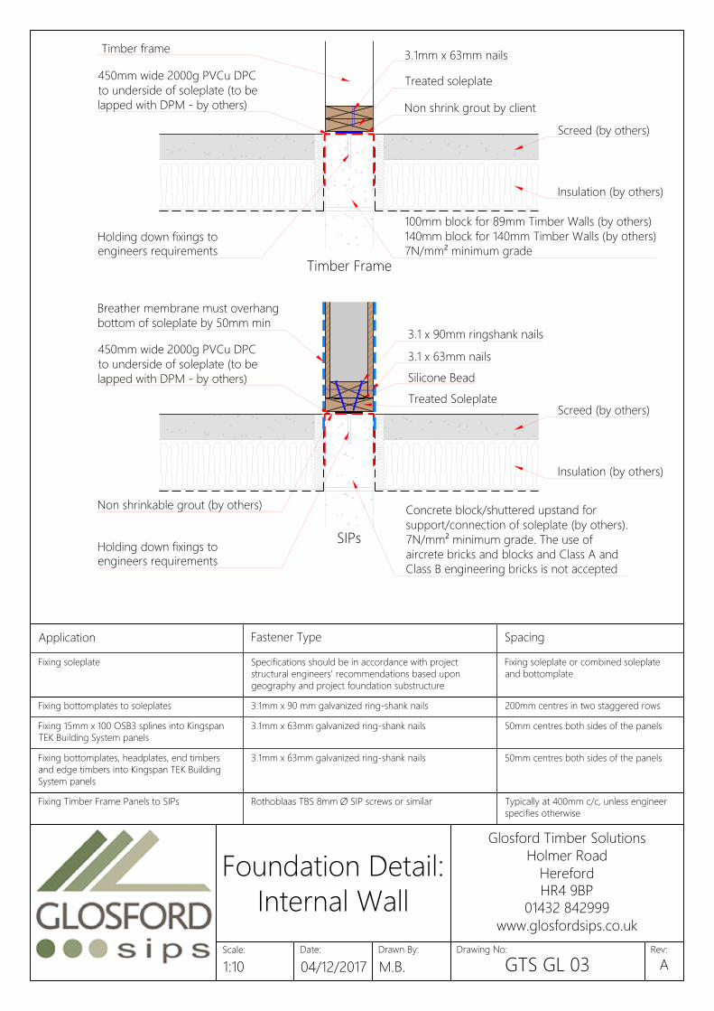
Non shrinkable grout (by others)
Silicone Bead
Timber Frame
SIPs
450mm wide 2000g PVCu DPC
to underside of soleplate (to be
lapped with DPM - by others)
Breather membrane must overhang
bottom of soleplate by 50mm min
Holding down fixings to
engineers requirements
3.1 x 90mm ringshank nails
Holding down fixings to
engineers requirements
3.1 x 63mm nails
100mm block for 89mm Timber Walls (by others)
140mm block for 140mm Timber Walls (by others)
7N/mm² minimum grade
Concrete block/shuttered upstand for
support/connection of soleplate (by others).
7N/mm² minimum grade. The use of
aircrete bricks and blocks and Class A and
Class B engineering bricks is not accepted
Timber frame
Treated soleplate
3.1mm x 63mm nails
Non shrink grout by client
Treated Soleplate
Screed (by others)
Screed (by others)
Insulation (by others)
Insulation (by others)
450mm wide 2000g PVCu DPC
to underside of soleplate (to be
lapped with DPM - by others)
Application Fastener Type Spacing
Fixing soleplate Specifications should be in accordance with project
structural engineers' recommendations based upon
geography and project foundation substructure
Fixing soleplate or combined soleplate
and bottomplate
Panel straps to substructure/foundations Specifications should be in accordance with project As per project structural engineers'Fixing bottomplates to soleplates 3.1mm x 90 mm galvanized ring-shank nails 200mm centres in two staggered rows
Fixing 15mm x 100 OSB3 splines into Kingspan
TEK Building System panels
3.1mm x 63mm galvanized ring-shank nails 50mm centres both sides of the panels
Fixing bottomplates, headplates, end timbers
and edge timbers into Kingspan TEK Building
System panels
3.1mm x 63mm galvanized ring-shank nails 50mm centres both sides of the panels
Fixing 100mm x 110 / 140mm insulated splines or 3.1mm x 63mm galvanized ring-shank nails 50mm centres both sides of the panelsFixing Timber Frame Panels to SIPs Rothoblaas TBS 8mm Ø SIP screws or similar Typically at 400mm c/c, unless engineer
specifies otherwise
Fixing Non-Load Bearing Timber Frame 3.1mm x 90 mm galvanized ring-shank nails Skew fix 2no nails per noggin
Date:
Glosford Timber Solutions
Holmer Road
Hereford
HR4 9BP
01432 842999
www.glosfordsips.co.uk
Scale: Drawn By: Drawing No: Rev:
Foundation Detail:
Internal Wall
1:10 04/12/2017 M.B. GTS GL 03A
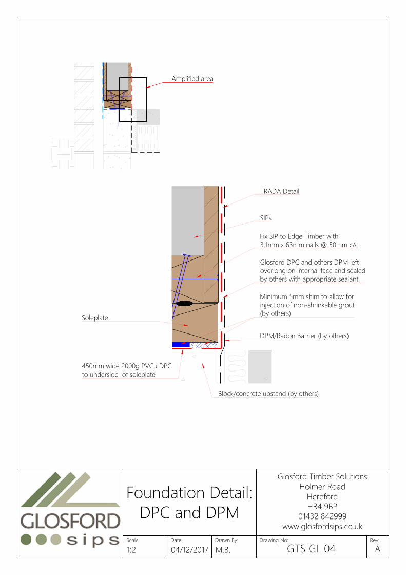
450mm wide 2000g PVCu DPC
to underside of soleplate
Minimum 5mm shim to allow for
injection of non-shrinkable grout
(by others)
DPM/Radon Barrier (by others)
Block/concrete upstand (by others)
Soleplate
Glosford DPC and others DPM left
overlong on internal face and sealed
by others with appropriate sealant
SIPs
TRADA Detail
Fix SIP to Edge Timber with
3.1mm x 63mm nails @ 50mm c/c
Amplified area
Date:
Glosford Timber Solutions
Holmer Road
Hereford
HR4 9BP
01432 842999
www.glosfordsips.co.uk
Scale: Drawn By: Drawing No: Rev:
Foundation Detail:
DPC and DPM
1:2 04/12/2017 M.B. GTS GL 04A
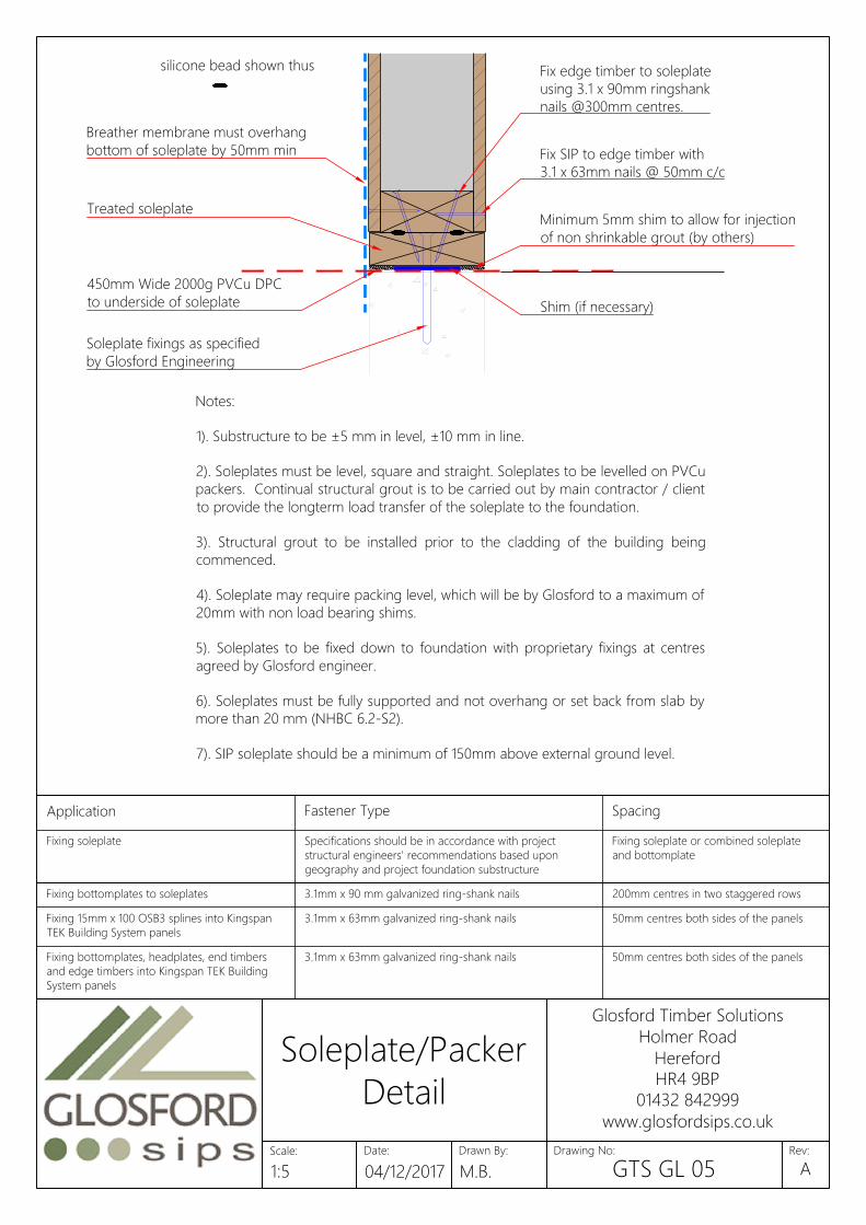
Notes:
1). Substructure to be ±5 mm in level, ±10 mm in line.
2). Soleplates must be level, square and straight. Soleplates to be levelled on PVCu
packers. Continual structural grout is to be carried out by main contractor / client
to provide the longterm load transfer of the soleplate to the foundation.
3). Structural grout to be installed prior to the cladding of the building being
commenced.
4). Soleplate may require packing level, which will be by Glosford to a maximum of
20mm with non load bearing shims.
5). Soleplates to be fixed down to foundation with proprietary fixings at centres
agreed by Glosford engineer.
6). Soleplates must be fully supported and not overhang or set back from slab by
more than 20 mm (NHBC 6.2-S2).
7). SIP soleplate should be a minimum of 150mm above external ground level.
silicone bead shown thus
Treated soleplate
450mm Wide 2000g PVCu DPC
to underside of soleplate
Breather membrane must overhang
bottom of soleplate by 50mm min
Minimum 5mm shim to allow for injection
of non shrinkable grout (by others)
Fix edge timber to soleplate
using 3.1 x 90mm ringshank
nails @300mm centres.
Soleplate fixings as specified
by Glosford Engineering
Shim (if necessary)
Fix SIP to edge timber with
3.1 x 63mm nails @ 50mm c/c
Application Fastener Type Spacing
Fixing soleplate Specifications should be in accordance with project
structural engineers' recommendations based upon
geography and project foundation substructure
Fixing soleplate or combined soleplate
and bottomplate
Panel straps to substructure/foundations Specifications should be in accordance with project As per project structural engineers'Fixing bottomplates to soleplates 3.1mm x 90 mm galvanized ring-shank nails 200mm centres in two staggered rows
Fixing 15mm x 100 OSB3 splines into Kingspan
TEK Building System panels
3.1mm x 63mm galvanized ring-shank nails 50mm centres both sides of the panels
Fixing bottomplates, headplates, end timbers
and edge timbers into Kingspan TEK Building
System panels
3.1mm x 63mm galvanized ring-shank nails 50mm centres both sides of the panels
Fixing 100mm x 110 / 140mm insulated splines or 3.1mm x 63mm galvanized ring-shank nails 50mm centres both sides of the panels
Date:
Glosford Timber Solutions
Holmer Road
Hereford
HR4 9BP
01432 842999
www.glosfordsips.co.uk
Scale: Drawn By: Drawing No: Rev:
Soleplate/Packer
Detail
1:5 04/12/2017 M.B. GTS GL 05A
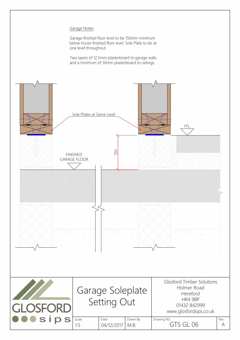
Garage Notes:
Garage finished floor level to be 150mm minimum
below house finished floor level. Sole Plate to be at
one level throughout.
Two layers of 12.5mm plasterboard to garage walls
and a minimum of 30mm plasterboard to ceilings.
FFL
FINISHED
GARAGE FLOOR
Sole Plates at Same Level
150
Date:
Glosford Timber Solutions
Holmer Road
Hereford
HR4 9BP
01432 842999
www.glosfordsips.co.uk
Scale: Drawn By: Drawing No: Rev:
Garage Soleplate
Setting Out
1:5 04/12/2017 M.B. GTS GL 06A

Breather membrane
3.1 x 63mm nails
100 x 140mm insulated spline
(100 x 140mm timber post if necessary)
Breather membrane
142mm SIPs
3.1 x 63mm nails
172mm SIPs
100 x 110mm insulated spline
(100 x 110mm timber post if necessary)
Expanding urethane
sealant in joints
Expanding urethane
sealant in joints
Application Fastener Type Spacing
Specifications should be in accordance with project Fixing soleplate or combined soleplateFixing 100mm x 110 / 140mm insulated splines or
timber posts into Kingspan TEK Building System
panels
3.1mm x 63mm galvanized ring-shank nails 50mm centres both sides of the panels
Fixing 100mm x 150mm bevelled headplate to 3.1mm x 63mm galvanized ring-shank nails 50mm centres both sides of the panels
Date:
Glosford Timber Solutions
Holmer Road
Hereford
HR4 9BP
01432 842999
www.glosfordsips.co.uk
Scale: Drawn By: Drawing No: Rev:
SIP-to-SIP
Connection Detail
1:5 04/12/2017 M.B. GTS WL 01A
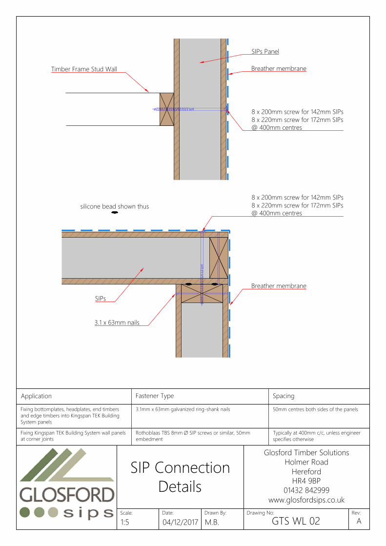
silicone bead shown thus
SIPs
Breather membrane
8 x 200mm screw for 142mm SIPs
8 x 220mm screw for 172mm SIPs
@ 400mm centres
Breather membrane
3.1 x 63mm nails
8 x 200mm screw for 142mm SIPs
8 x 220mm screw for 172mm SIPs
@ 400mm centres
Timber Frame Stud Wall
SIPs Panel
Application Fastener Type Spacing
Specifications should be in accordance with project Fixing soleplate or combined soleplateFixing bottomplates, headplates, end timbers
and edge timbers into Kingspan TEK Building
System panels
3.1mm x 63mm galvanized ring-shank nails 50mm centres both sides of the panels
Fixing 100mm x 110 / 140mm insulated splines or 3.1mm x 63mm galvanized ring-shank nails 50mm centres both sides of the panelsFixing Kingspan TEK Building System wall panels
at corner joints
Rothoblaas TBS 8mm Ø SIP screws or similar, 50mm
embedment
Typically at 400mm c/c, unless engineer
specifies otherwise
Fixing Kingspan TEK Building System roof SIP screws or similar, 50mm Typically at 200mm c/c, unless engineer
Date:
Glosford Timber Solutions
Holmer Road
Hereford
HR4 9BP
01432 842999
www.glosfordsips.co.uk
Scale: Drawn By: Drawing No: Rev:
SIP Connection
Details
1:5 04/12/2017 M.B. GTS WL 02A
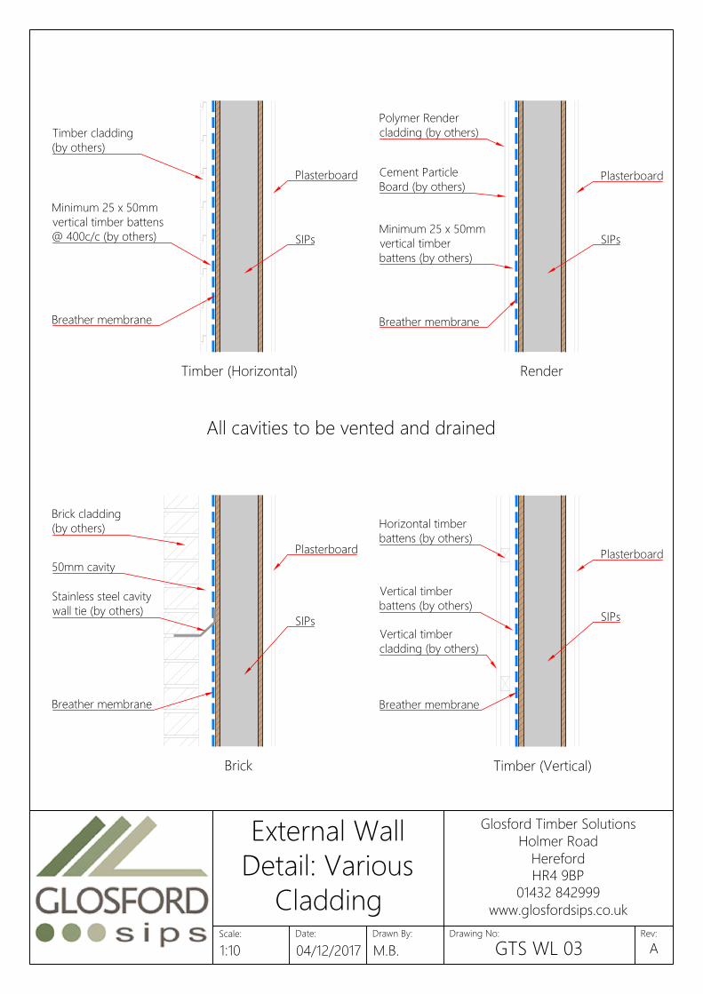
Horizontal timber
battens (by others)
Brick
Timber (Horizontal) Render
Timber (Vertical)
Polymer Render
cladding (by others)
Cement Particle
Board (by others)
Minimum 25 x 50mm
vertical timber
battens (by others)
Timber cladding
(by others)
Breather membrane
Breather membrane
Minimum 25 x 50mm
vertical timber battens
@ 400c/c (by others)
50mm cavity
Plasterboard
SIPs
Brick cladding
(by others)
Breather membrane
Plasterboard
SIPs
Plasterboard
SIPs
Vertical timber
cladding (by others)
Plasterboard
Vertical timber
battens (by others)
Stainless steel cavity
wall tie (by others)
All cavities to be vented and drained
Breather membrane
SIPs
Date:
Glosford Timber Solutions
Holmer Road
Hereford
HR4 9BP
01432 842999
www.glosfordsips.co.uk
Scale: Drawn By: Drawing No: Rev:
External Wall
Detail: Various
Cladding
1:10 04/12/2017 M.B. GTS WL 03A

silicone bead shown thus
89 8972
50
25 x 38mm vertical timber
battens (by others)
Plasterboard lining. Min
22kg/m² to Robust Details
(by others)
9.5mm OSB sheathing to
party walls as required by
timber frame engineer
65mm polythene wrapped mineral
wool cavity barrier (by others)
SIPs
Stainless steel wall ties fixed with
stainless steel screws (by others)
Breather membrane with
vertical laps of 150mm min
Insulation for acoustic
purposes (by others)
Rockwool Flexi (or similar
approved) to full fill cavity
8mm ∅ SIP Screw
Application Fastener Type Spacing
Specifications should be in accordance with project Fixing soleplate or combined soleplateFixing Timber Frame Panels to SIPs Rothoblaas TBS 8mm Ø SIP screws or similar Typically at 400mm c/c, unless engineer
specifies otherwise
Fixing Non-Load Bearing Timber Frame 3.1mm x 90 mm galvanized ring-shank nails Skew fix 2no nails per noggin
Date:
Glosford Timber Solutions
Holmer Road
Hereford
HR4 9BP
01432 842999
www.glosfordsips.co.uk
Scale: Drawn By: Drawing No: Rev:
External Party
Wall Plan Junction
1:5 04/12/2017 M.B. GTS WL 04A
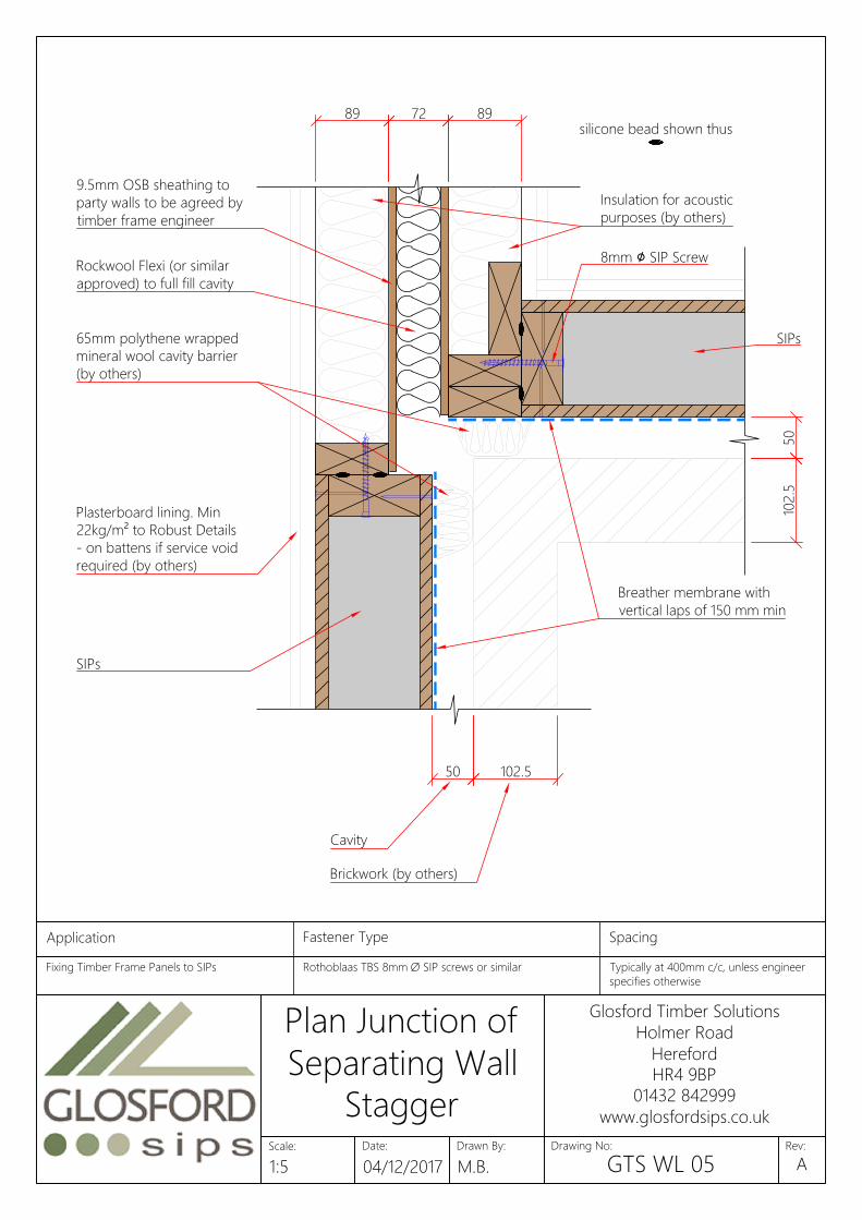
89 72 89
102.5
50
50 102.5
silicone bead shown thus
SIPs
SIPs
9.5mm OSB sheathing to
party walls to be agreed by
timber frame engineer
65mm polythene wrapped
mineral wool cavity barrier
(by others)
Plasterboard lining. Min
22kg/m² to Robust Details
- on battens if service void
required (by others)
Breather membrane with
vertical laps of 150 mm min
8mm ∅ SIP Screw
Insulation for acoustic
purposes (by others)
Rockwool Flexi (or similar
approved) to full fill cavity
Cavity
Brickwork (by others)
Application Fastener Type Spacing
Specifications should be in accordance with project Fixing soleplate or combined soleplateFixing Timber Frame Panels to SIPs Rothoblaas TBS 8mm Ø SIP screws or similar Typically at 400mm c/c, unless engineer
specifies otherwise
Fixing Non-Load Bearing Timber Frame 3.1mm x 90 mm galvanized ring-shank nails Skew fix 2no nails per noggin
Date:
Glosford Timber Solutions
Holmer Road
Hereford
HR4 9BP
01432 842999
www.glosfordsips.co.uk
Scale: Drawn By: Drawing No: Rev:
Plan Junction of
Separating Wall
Stagger
1:5 04/12/2017 M.B. GTS WL 05A
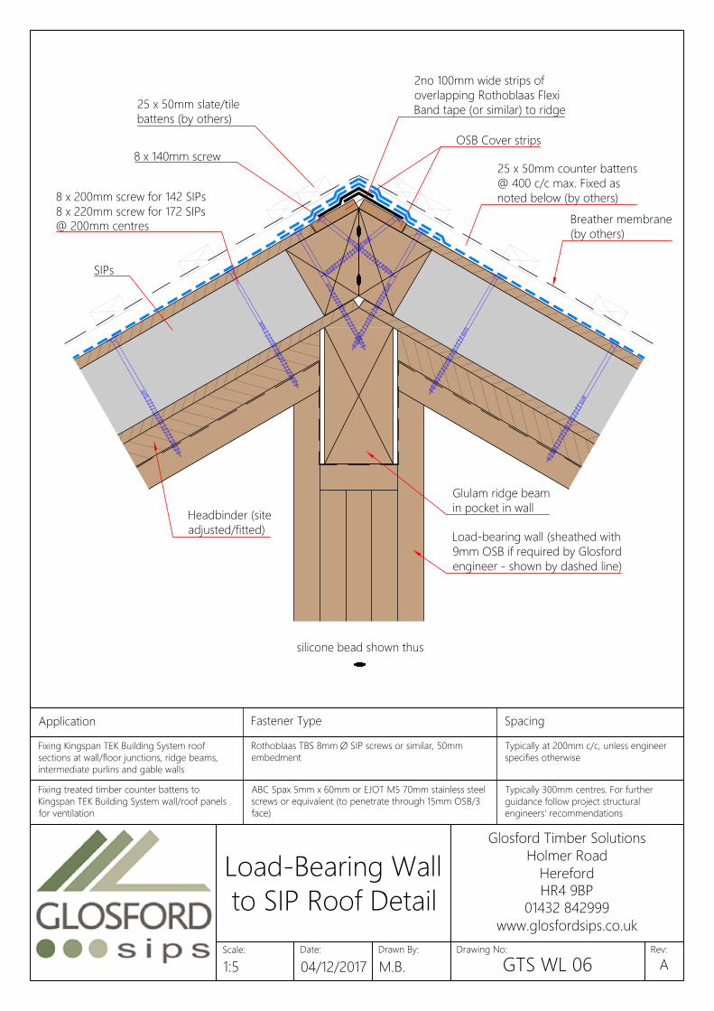
silicone bead shown thus
SIPs
Glulam ridge beam
in pocket in wall
Headbinder (site
adjusted/fitted)
Load-bearing wall (sheathed with
9mm OSB if required by Glosford
engineer - shown by dashed line)
8 x 200mm screw for 142 SIPs
8 x 220mm screw for 172 SIPs
@ 200mm centres
OSB Cover strips
Breather membrane
(by others)
8 x 140mm screw
2no 100mm wide strips of
overlapping Rothoblaas Flexi
Band tape (or similar) to ridge
25 x 50mm counter battens
@ 400 c/c max. Fixed as
noted below (by others)
25 x 50mm slate/tile
battens (by others)
Application Fastener Type Spacing
Specifications should be in accordance with project Fixing soleplate or combined soleplateFixing Kingspan TEK Building System roof
sections at wall/floor junctions, ridge beams,
intermediate purlins and gable walls
Rothoblaas TBS 8mm Ø SIP screws or similar, 50mm
embedment
Typically at 200mm c/c, unless engineer
specifies otherwise
Fixing joist hangers to headplate or laminated 3.75mm x 32mm square twist shank nails or Simpson N10 Into side and top of headplate locationsFixing treated timber counter battens to
Kingspan TEK Building System wall/roof panels
for ventilation
ABC Spax 5mm x 60mm or EJOT M5 70mm stainless steel
screws or equivalent (to penetrate through 15mm OSB/3
face)
Typically 300mm centres. For further
guidance follow project structural
engineers' recommendations
Fixing Timber Frame to Soleplate 3.1mm x 63mm galvanized ring-shank nails 200mm centres in two staggered rows
Date:
Glosford Timber Solutions
Holmer Road
Hereford
HR4 9BP
01432 842999
www.glosfordsips.co.uk
Scale: Drawn By: Drawing No: Rev:
Load-Bearing Wall
to SIP Roof Detail
1:5 04/12/2017 M.B. GTS WL 06A
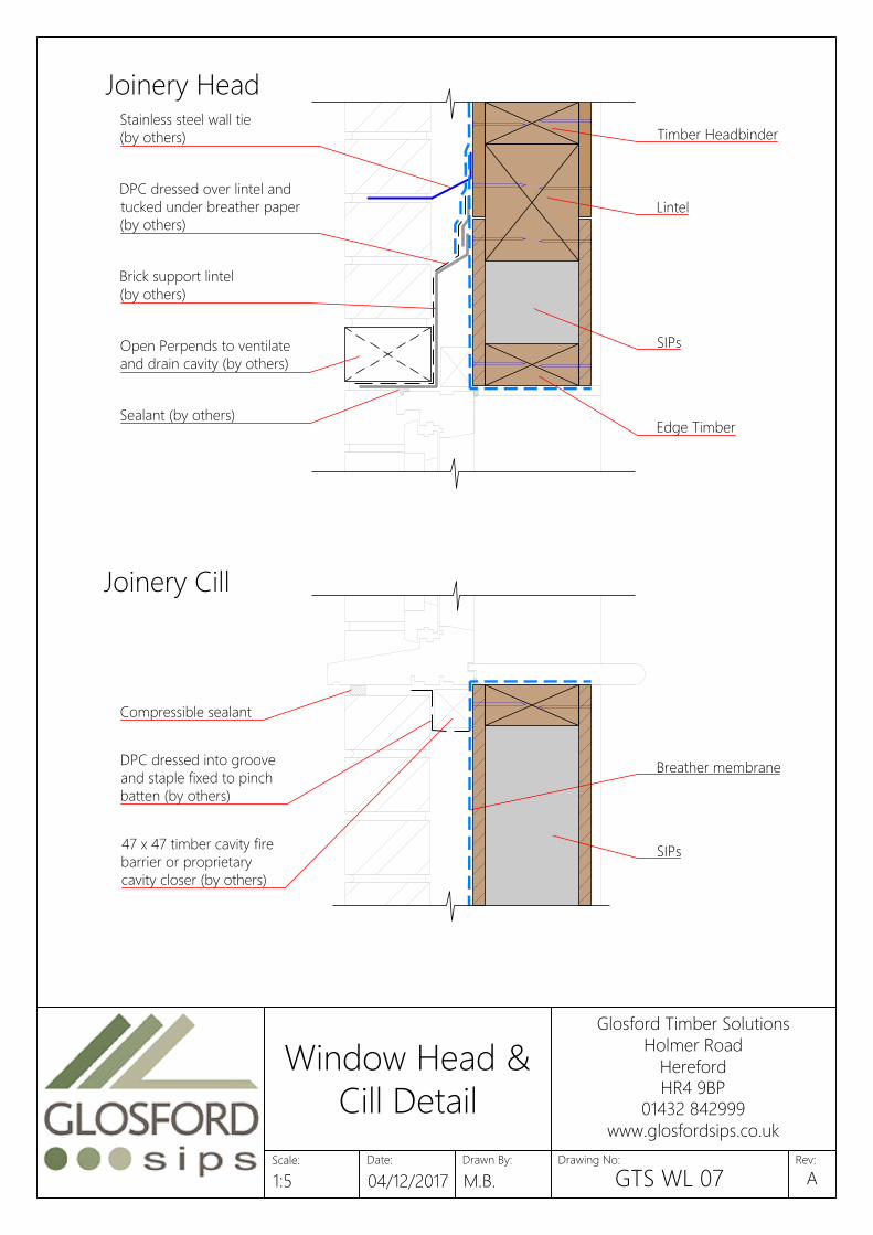
DPC dressed over lintel and
tucked under breather paper
(by others)
Joinery Head
Joinery Cill
Brick support lintel
(by others)
Sealant (by others)
SIPs
Compressible sealant
47 x 47 timber cavity fire
barrier or proprietary
cavity closer (by others)
DPC dressed into groove
and staple fixed to pinch
batten (by others)
Breather membrane
SIPs
Lintel
Timber Headbinder
Edge Timber
Open Perpends to ventilate
and drain cavity (by others)
Stainless steel wall tie
(by others)
Date:
Glosford Timber Solutions
Holmer Road
Hereford
HR4 9BP
01432 842999
www.glosfordsips.co.uk
Scale: Drawn By: Drawing No: Rev:
Window Head &
Cill Detail
1:5 04/12/2017 M.B. GTS WL 07A
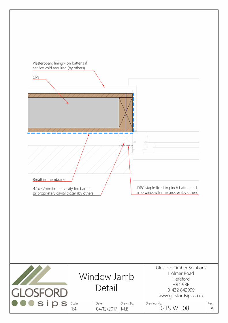
Plasterboard lining - on battens if
service void required (by others)
47 x 47mm timber cavity fire barrier
or proprietary cavity closer (by others)
Breather membrane
DPC staple fixed to pinch batten and
into window frame groove (by others)
SIPs
Date:
Glosford Timber Solutions
Holmer Road
Hereford
HR4 9BP
01432 842999
www.glosfordsips.co.uk
Scale: Drawn By: Drawing No: Rev:
Window Jamb
Detail
1:4 04/12/2017 M.B. GTS WL 08A

Threshold may be omitted
323 tol.
Glosford SIPs
Standard Door Openings
Imperial doors (1981 high)
Leaf Structural opening
457 534x2040
533 610x2040
610 687x2040
686 763x2040
711 788x2040
762 839x2040
838 915x2040
864 941x2040
915 992x2040
Pair 457 994x2040
Pair 533 1146x2040
Pair 610 1300x2040
Pair 686 1452x2040
Pair 711 1502x2040
Pair 762 1604x2040
Pair 838 1756x2040
Pair 864 1808x2040
Metric Doors (2040 high)
Leaf Structural opening
426 510x2100
526 610x2100
626 710x2100
726 810x2100
826 910x2100
926 1010x2100
Pair 426 940x2100
Pair 526 1140x2100
Pair 626 1340x2100
Pair 726 1540x2100
3.5
Leaf Size
3.5
32 3 tol.
NOTE: Internal door sizes to be used by Glosford if no internal door schedule is supplied.
2040 structural o
pening
fo
r 1981 d
oo
r leaf
2100 structural o
pening
fo
r 2040 d
oo
r leaf
15
3
Do
or leaf 1981/2040
3
32
6 to
l.
Pack between lining & jamb
studs at fixing positions
Pack between lining & jamb
studs at fixing positions
Date:
Glosford Timber Solutions
Holmer Road
Hereford
HR4 9BP
01432 842999
www.glosfordsips.co.uk
Scale: Drawn By: Drawing No: Rev:
Internal Door
Lining Detail
1:2.5 04/12/2017 M.B. GTS WL 09A

25
min
SIPs
External grille (by others)
Internal grille (by others)
Weephole over air brick
(by others)
Fully filled with mineral
wool (by others)
Breather membrane
Wall Tie (by others)
Cavity barrier (by others)
25
min
Date:
Glosford Timber Solutions
Holmer Road
Hereford
HR4 9BP
01432 842999
www.glosfordsips.co.uk
Scale: Drawn By: Drawing No: Rev:
MVHR System
1:4 04/12/2017 M.B. GTS WL 10A
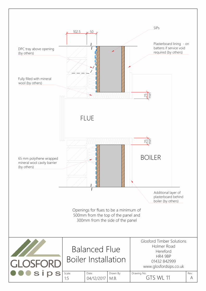
102.5 50
FLUE
BOILER
25
min
25
min
Openings for flues to be a minimum of
500mm from the top of the panel and
300mm from the side of the panel
SIPs
DPC tray above opening
(by others)
65 mm polythene wrapped
mineral wool cavity barrier
(by others)
Plasterboard lining - on
battens if service void
required (by others)
Additional layer of
plasterboard behind
boiler (by others)
Fully filled with mineral
wool (by others)
Date:
Glosford Timber Solutions
Holmer Road
Hereford
HR4 9BP
01432 842999
www.glosfordsips.co.uk
Scale: Drawn By: Drawing No: Rev:
Balanced Flue
Boiler Installation
1:5 04/12/2017 M.B. GTS WL 11A
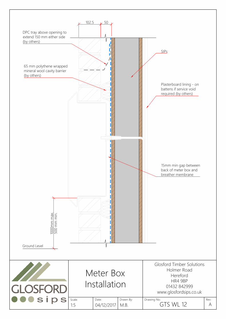
50102.5
1000m
m m
ax.
500 m
m m
in.
Ground Level
SIPs
DPC tray above opening to
extend 150 mm either side
(by others)
Plasterboard lining - on
battens if service void
required (by others)
15mm min gap between
back of meter box and
breather membrane
65 mm polythene wrapped
mineral wool cavity barrier
(by others)
Date:
Glosford Timber Solutions
Holmer Road
Hereford
HR4 9BP
01432 842999
www.glosfordsips.co.uk
Scale: Drawn By: Drawing No: Rev:
Meter Box
Installation
1:5 04/12/2017 M.B. GTS WL 12A
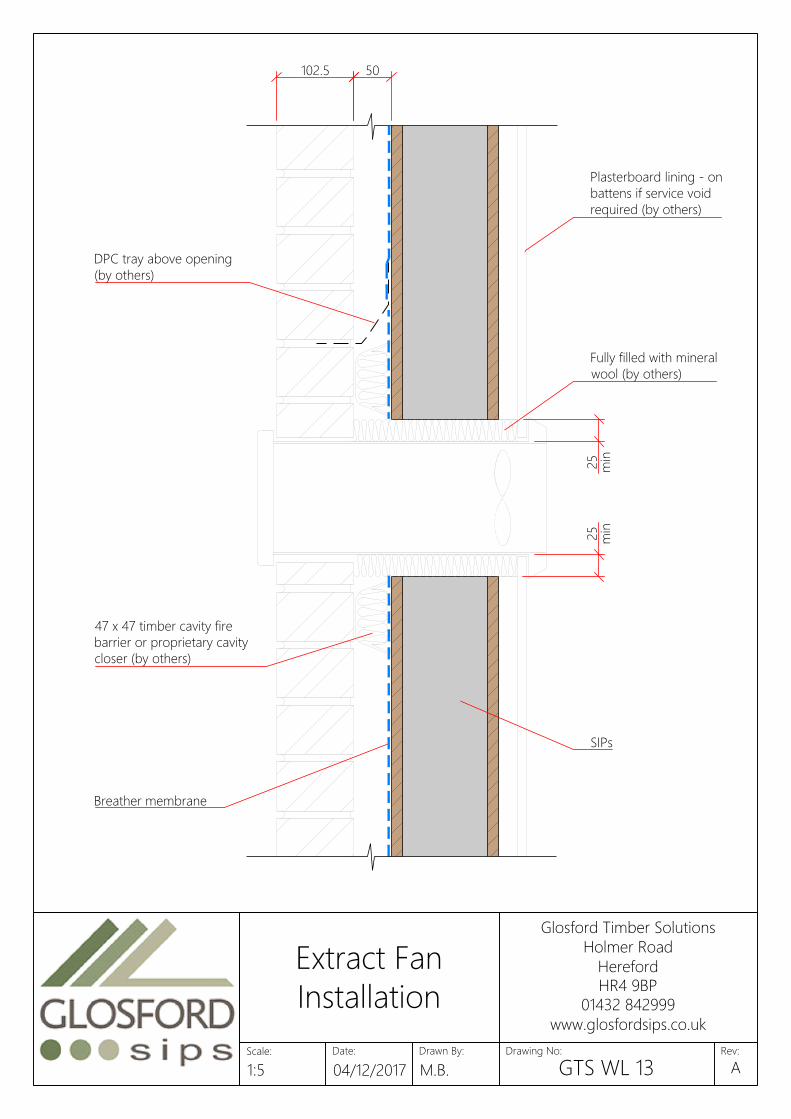
102.5 50
25
min
SIPs
DPC tray above opening
(by others)
47 x 47 timber cavity fire
barrier or proprietary cavity
closer (by others)
Plasterboard lining - on
battens if service void
required (by others)
Fully filled with mineral
wool (by others)
25
min
Breather membrane
Date:
Glosford Timber Solutions
Holmer Road
Hereford
HR4 9BP
01432 842999
www.glosfordsips.co.uk
Scale: Drawn By: Drawing No: Rev:
Extract Fan
Installation
1:5 04/12/2017 M.B. GTS WL 13A
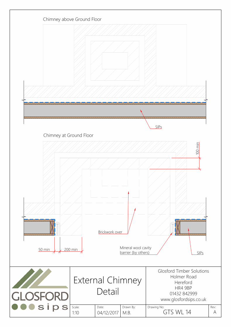
50 min
Chimney above Ground Floor
100 m
in
200 min
Chimney at Ground Floor
Mineral wool cavity
barrier (by others)
SIPs
SIPs
Brickwork over
Date:
Glosford Timber Solutions
Holmer Road
Hereford
HR4 9BP
01432 842999
www.glosfordsips.co.uk
Scale: Drawn By: Drawing No: Rev:
External Chimney
Detail
1:10 04/12/2017 M.B. GTS WL 14A

Roofing Underlay
(by others)
Continuous 333 x 50mm Fireus
Fireshield fire and cavity barrier
Roof truss
100mm (min) mineral wool
insulation between ceiling
joists - 10kg/m³ min (by others)
600
Plasterboard ceiling (by others)
2 layers of plasterboard
to Robust Details -
www.robustdetails.com
(by others)
Insulation for acoustic
purposes - not needed
above ceiling (by others)
Rockwool Flexi (or similar
approved) to full fill cavity
Date:
Glosford Timber Solutions
Holmer Road
Hereford
HR4 9BP
01432 842999
www.glosfordsips.co.uk
Scale: Drawn By: Drawing No: Rev:
Party Wall to Roof
Truss Detail
1:10 04/12/2017 M.B. GTS WL 15A
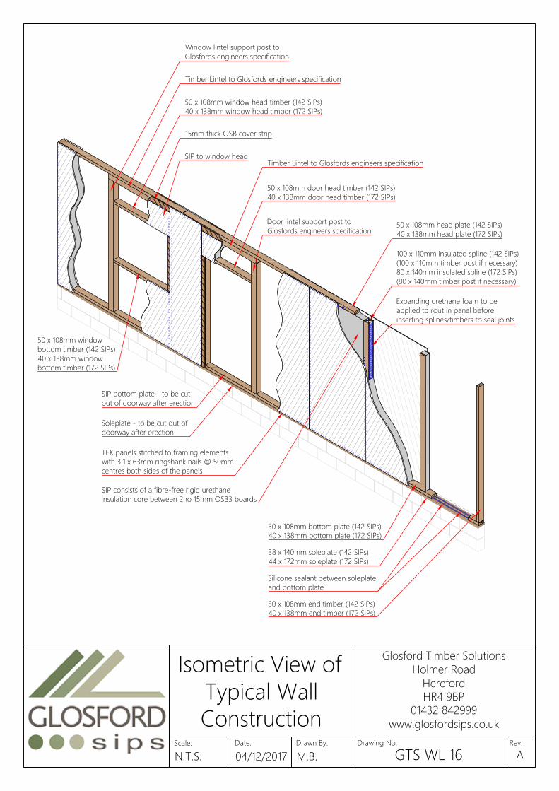
Timber Lintel to Glosfords engineers specification
50 x 108mm window head timber (142 SIPs)
40 x 138mm window head timber (172 SIPs)
50 x 108mm head plate (142 SIPs)
40 x 138mm head plate (172 SIPs)
Window lintel support post to
Glosfords engineers specification
15mm thick OSB cover strip
SIP to window head
Timber Lintel to Glosfords engineers specification
50 x 108mm door head timber (142 SIPs)
40 x 138mm door head timber (172 SIPs)
Door lintel support post to
Glosfords engineers specification
SIP bottom plate - to be cut
out of doorway after erection
Soleplate - to be cut out of
doorway after erection
100 x 110mm insulated spline (142 SIPs)
(100 x 110mm timber post if necessary)
80 x 140mm insulated spline (172 SIPs)
(80 x 140mm timber post if necessary)
TEK panels stitched to framing elements
with 3.1 x 63mm ringshank nails @ 50mm
centres both sides of the panels
Expanding urethane foam to be
applied to rout in panel before
inserting splines/timbers to seal joints
SIP consists of a fibre-free rigid urethane
insulation core between 2no 15mm OSB3 boards
50 x 108mm window
bottom timber (142 SIPs)
40 x 138mm window
bottom timber (172 SIPs)
50 x 108mm bottom plate (142 SIPs)
40 x 138mm bottom plate (172 SIPs)
38 x 140mm soleplate (142 SIPs)
44 x 172mm soleplate (172 SIPs)
Silicone sealant between soleplate
and bottom plate
50 x 108mm end timber (142 SIPs)
40 x 138mm end timber (172 SIPs)
Date:
Glosford Timber Solutions
Holmer Road
Hereford
HR4 9BP
01432 842999
www.glosfordsips.co.uk
Scale: Drawn By: Drawing No: Rev:
Isometric View of
Typical Wall
Construction
N.T.S. 04/12/2017 M.B. GTS WL 16A

47 x 72mm
Continuous packer
3.1 x 63mm nails
47 x 72mm Intermediate joists packer
SIPs
90mm ringshank nails
Breather membrane
Bottom Plate
Engineered posi floor system with
22mm thick weather resistant
chipboard (minimum weight 15kg/m²)
Minimum 100mm Mineral Fibre
(10-33kg/m²) insulation to floor
zone (by others)
Application Fastener Type Spacing
Specifications should be in accordance with project Fixing soleplate or combined soleplateFixing bottomplates, headplates, end timbers
and edge timbers into Kingspan TEK Building
System panels
3.1mm x 63mm galvanized ring-shank nails 50mm centres both sides of the panels
Fixing 100mm x 110 / 140mm insulated splines or 3.1mm x 63mm galvanized ring-shank nails 50mm centres both sides of the panelsFixing bottomplates to soleplates 3.1mm x 90 mm galvanized ring-shank nails 200mm centres in two staggered rows
Fixing 15mm x 100 OSB3 splines into Kingspan 3.1mm x 63mm galvanized ring-shank nails 50mm centres both sides of the panelsFixing joist hangers to headplate or laminated
beams (fixings may vary depending on
specification of joist hanger - please refer to
manufacturers' instructions floor systems)
3.75mm x 32mm square twist shank nails or Simpson N10
nails
Into side and top of headplate locations
marked out
Fixing I-beams/joist to joist hanger (fasteners 3.75mm x 32mm square twist shank nails or Simpson N10 In pre-drilled holes for bottom flange
Date:
Glosford Timber Solutions
Holmer Road
Hereford
HR4 9BP
01432 842999
www.glosfordsips.co.uk
Scale: Drawn By: Drawing No: Rev:
Posi Joist Detail
for Houses
1:10 04/12/2017 M.B. GTS FL 01A

47mm x 72mm
Intermediate joists packer
Engineered posi floor system
with 18mm thick OSB3 sub-deck
Acoustic Floor System
(by others if required)
Resilient bar
(by others)
SIPs
65 mm polythene
wrapped mineral wool
cavity barrier (by others)
47 x 72mm
Continuous packer
Breather membrane
Bottom Plate
Glulam Beam for
Acoustic Performance
90mm ringshank nails
Application Fastener Type Spacing
Specifications should be in accordance with project Fixing soleplate or combined soleplateFixing bottomplates, headplates, end timbers
and edge timbers into Kingspan TEK Building
System panels
3.1mm x 63mm galvanized ring-shank nails 50mm centres both sides of the panels
Fixing 100mm x 110 / 140mm insulated splines or 3.1mm x 63mm galvanized ring-shank nails 50mm centres both sides of the panelsFixing bottomplates to soleplates 3.1mm x 90 mm galvanized ring-shank nails 200mm centres in two staggered rows
Fixing 15mm x 100 OSB3 splines into Kingspan 3.1mm x 63mm galvanized ring-shank nails 50mm centres both sides of the panelsFixing joist hangers to headplate or laminated
beams (fixings may vary depending on
specification of joist hanger - please refer to
manufacturers' instructions floor systems)
3.75mm x 32mm square twist shank nails or Simpson N10
nails
Into side and top of headplate locations
marked out
Fixing I-beams/joist to joist hanger (fasteners 3.75mm x 32mm square twist shank nails or Simpson N10 In pre-drilled holes for bottom flange
Date:
Glosford Timber Solutions
Holmer Road
Hereford
HR4 9BP
01432 842999
www.glosfordsips.co.uk
Scale: Drawn By: Drawing No: Rev:
Posi Joist Detail
for Flats
1:10 04/12/2017 M.B. GTS FL 02A

Typical party floor / party wall posi joist detail.
Alternative acoustic floor systems available.
Acoustic floor build up and resilient bar by other.
Engineered posi floor system
with 18mm thick OSB3 sub-deck
2 Layers of plasterboard
as per Robust Details -
www.robustdetails.com
(by others)
Timber blocking2 Layers of Plasterboard
(by others)
Resilient Bar (by others)
Cavity full filled with Rockwool
Flexi (or similar approved)
Acoustic Floor System
(by others if required)
Insulation required for
acoustic performance
(by others)
250 min.
9mm OSB sheathing (sheathing
as required by Glosford engineer)
90mm ringshank nails
3.1 x 63mm nails
8 x 160mm TBS screws
Application Fastener Type Spacing
Specifications should be in accordance with project Fixing soleplate or combined soleplateFixing bottomplates, headplates, end timbers
and edge timbers into Kingspan TEK Building
System panels
3.1mm x 63mm galvanized ring-shank nails 50mm centres both sides of the panels
Fixing 100mm x 110 / 140mm insulated splines or 3.1mm x 63mm galvanized ring-shank nails 50mm centres both sides of the panels
Fixing joist hangers to headplate or laminated
beams (fixings may vary depending on
specification of joist hanger - please refer to
manufacturers' instructions floor systems)
3.75mm x 32mm square twist shank nails or Simpson N10
nails
Into side and top of headplate locations
marked out
Fixing I-beams/joist to joist hanger (fasteners 3.75mm x 32mm square twist shank nails or Simpson N10 In pre-drilled holes for bottom flange
Fixing bottomplates to soleplates 3.1mm x 90 mm galvanized ring-shank nails 200mm centres in two staggered rows
Fixing 15mm x 100 OSB3 splines into Kingspan 3.1mm x 63mm galvanized ring-shank nails 50mm centres both sides of the panels
Date:
Glosford Timber Solutions
Holmer Road
Hereford
HR4 9BP
01432 842999
www.glosfordsips.co.uk
Scale: Drawn By: Drawing No: Rev:
Party Floor Posi
Joist Detail
1:10 04/12/2017 M.B. GTS FL 03A
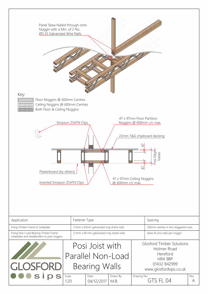
Floor Noggins @ 600mm Centres
Key:
Ceiling Noggins @ 600mm Centres
Both Floor & Ceiling Noggins
47 x 97mm Floor Partition
Noggins @ 600mm c/c max.
Inverted Simpson ZS47N Clips
47 x 97mm Ceiling Noggins
@ 600mm c/c max.
Po
si D
ep
th
Varies
47
47
Simpson ZS47N Clips
Plasterboard (by others)
22mm T&G chipboard decking
Panel Skew Nailed through onto
Noggin with a Min. of 2 No.
Ø3.35 Galvanized Wire Nails
Application Fastener Type Spacing
Specifications should be in accordance with project Fixing soleplate or combined soleplateFixing Timber Frame to Soleplate 3.1mm x 63mm galvanized ring-shank nails 200mm centres in two staggered rows
Fixing Timber Frame Panels to SIPs Typically at 400mm c/c, unless engineerFixing Non-Load Bearing Timber Frame
soleplates and headbinders to joist noggins
3.1mm x 90 mm galvanized ring-shank nails Skew fix 2no nails per noggin
Fixing Kingspan TEK Building System to oak SIP screws or similar, 50mm Typically at 400mm c/c, unless engineer
Date:
Glosford Timber Solutions
Holmer Road
Hereford
HR4 9BP
01432 842999
www.glosfordsips.co.uk
Scale: Drawn By: Drawing No: Rev:
Posi Joist with
Parallel Non-Load
Bearing Walls
1:20 04/12/2017 M.B. GTS FL 04A
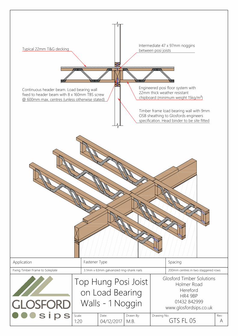
Intermediate 47 x 97mm noggins
between posi joists
Continuous header beam. Load bearing wall
fixed to header beam with 8 x 160mm TBS screw
@ 600mm max. centres (unless otherwise stated)
Typical 22mm T&G decking
Engineered posi floor system with
22mm thick weather resistant
chipboard (minimum weight 15kg/m²)
Timber frame load bearing wall with 9mm
OSB sheathing to Glosfords engineers
specification. Head binder to be site fitted
Application Fastener Type Spacing
Specifications should be in accordance with project Fixing soleplate or combined soleplateFixing Timber Frame to Soleplate 3.1mm x 63mm galvanized ring-shank nails 200mm centres in two staggered rows
Fixing Timber Frame Panels to SIPs Typically at 400mm c/c, unless engineer
Date:
Glosford Timber Solutions
Holmer Road
Hereford
HR4 9BP
01432 842999
www.glosfordsips.co.uk
Scale: Drawn By: Drawing No: Rev:
Top Hung Posi Joist
on Load Bearing
Walls - 1 Noggin
1:20 04/12/2017 M.B. GTS FL 05A

Intermediate 47 x 72mm
noggins between posi joists
Continuous header beam. Load
bearing wall fixed to header beam with
8 x 160mm TBS screw @ 600mm max.
centres (unless otherwise stated)
Typical 22mm T&G decking
Engineered posi floor system with
22mm thick weather resistant
chipboard (minimum weight 15kg/m²)
Timber frame load bearing wall with 9mm
OSB sheathing to Glosfords engineers
specification. Head binder to be site fitted
Intermediate 47 x 72mm
noggins between posi joists
Posi joists of different widths
Application Fastener Type Spacing
Specifications should be in accordance with project Fixing soleplate or combined soleplateFixing Timber Frame to Soleplate 3.1mm x 63mm galvanized ring-shank nails 200mm centres in two staggered rows
Fixing Timber Frame Panels to SIPs Typically at 400mm c/c, unless engineer
Date:
Glosford Timber Solutions
Holmer Road
Hereford
HR4 9BP
01432 842999
www.glosfordsips.co.uk
Scale: Drawn By: Drawing No: Rev:
Top Hung Posi Joist
on Load Bearing
Walls - 2 Noggins
1:20 04/12/2017 M.B. GTS FL 06A

Strongback Minimum Requirements Below:
47 x 97mm* TR26 timber for 225 & 253mm deep Joists
47 x 147mm* TR26 timber for 304 & 373mm deep Joists
Strongback brace tight to underside of
top chord (depth to suit - see below)
Strongback twice nailed to vertical
Strongback bracing required to
clear spans over approx. 4000mm
Date:
Glosford Timber Solutions
Holmer Road
Hereford
HR4 9BP
01432 842999
www.glosfordsips.co.uk
Scale: Drawn By: Drawing No: Rev:
Typical Strongback
Detail
1:15 04/12/2017 M.B. GTS FL 07A

Strongback Nailed to Change
of Span Noggin using 2No.
Ø3.1 x 90mm Nails
38 x 89mm Timber Blocks fixed
using 2No. Ø3.1 x 90mm Nails
to Top and Bottom Chords
Posi Type 1
Posi Type 2
View on Posi Type 1
View on Posi Type 2
Date:
Glosford Timber Solutions
Holmer Road
Hereford
HR4 9BP
01432 842999
www.glosfordsips.co.uk
Scale: Drawn By: Drawing No: Rev:
Strongback Change
of Span Detail
1:20 04/12/2017 M.B. GTS FL 08A
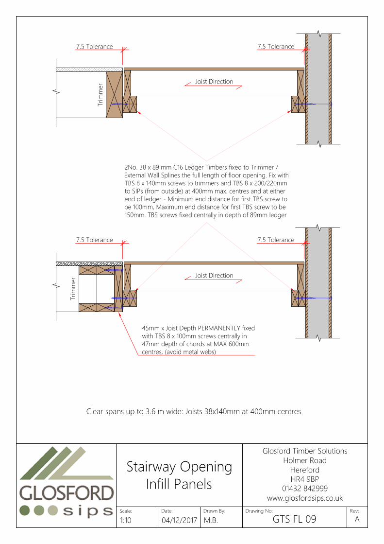
Trim
mer
2No. 38 x 89 mm C16 Ledger Timbers fixed to Trimmer /
External Wall Splines the full length of floor opening. Fix with
TBS 8 x 140mm screws to trimmers and TBS 8 x 200/220mm
to SIPs (from outside) at 400mm max. centres and at either
end of ledger - Minimum end distance for first TBS screw to
be 100mm, Maximum end distance for first TBS screw to be
150mm. TBS screws fixed centrally in depth of 89mm ledger
Trim
mer
Clear spans up to 3.6 m wide: Joists 38x140mm at 400mm centres
7.5 Tolerance 7.5 Tolerance
Joist Direction
7.5 Tolerance 7.5 Tolerance
45mm x Joist Depth PERMANENTLY fixed
with TBS 8 x 100mm screws centrally in
47mm depth of chords at MAX 600mm
centres, (avoid metal webs)
Joist Direction
Date:
Glosford Timber Solutions
Holmer Road
Hereford
HR4 9BP
01432 842999
www.glosfordsips.co.uk
Scale: Drawn By: Drawing No: Rev:
Stairway Opening
Infill Panels
1:10 04/12/2017 M.B. GTS FL 09A

silicone bead shown thus
3.1 x 63mm nails
15mm OSB cover strip
Wall SIPs
Timber Wall Plate
8 x 200mm screw for 142mm SIPs
8 x 220mm screw for 172mm SIPs
Roof SIPs
Breather membrane
Plumb and seatcut for fascia
& soffit. Site tolerance 10mm
for position and alignment
to be packed
Breather membrane
(by others)
25 x 50mm counter-battens
@ 400 c/c max. fixed as
noted below (by others)
25 x 50mm slate/tile
battens (by others)
Tilting fillet (by others)
Proprietary fascia
board (by others)
Application Fastener Type Spacing
Specifications should be in accordance with project Fixing soleplate or combined soleplateFixing bottomplates, headplates, end timbers
and edge timbers into Kingspan TEK Building
System panels
3.1mm x 63mm galvanized ring-shank nails 50mm centres both sides of the panels
Fixing 100mm x 110 / 140mm insulated splines or 3.1mm x 63mm galvanized ring-shank nails 50mm centres both sides of the panelsFixing Kingspan TEK Building System roof
sections at wall/floor junctions, ridge beams,
intermediate purlins and gable walls
Rothoblaas TBS 8mm Ø SIP screws or similar, 50mm
embedment
Typically at 200mm c/c, unless engineer
specifies otherwise
Fixing joist hangers to headplate or laminated 3.75mm x 32mm square twist shank nails or Simpson N10 Into side and top of headplate locationsFixing treated timber counter battens to
Kingspan TEK Building System wall/roof panels
for ventilation
ABC Spax 5mm x 60mm or EJOT M5 70mm stainless steel
screws or equivalent (to penetrate through 15mm OSB/3
face)
Typically 300mm centres. For further
guidance follow project structural
engineers' recommendations
Fixing Timber Frame to Soleplate 3.1mm x 63mm galvanized ring-shank nails 200mm centres in two staggered rows
Date:
Glosford Timber Solutions
Holmer Road
Hereford
HR4 9BP
01432 842999
www.glosfordsips.co.uk
Scale: Drawn By: Drawing No: Rev:
Eaves Detail
1:5 04/12/2017 M.B. GTS RF 01A

silicone bead shown thus
Glulam ridge beam
8 x 200mm screw for 142mm SIPs
8 x 220mm screw for 172mm SIPs
OSB Cover strips
2no 100mm wide strips of
overlapping Rothoblaas Flexi
Band tape (or similar) to ridge
25 x 50mm counter battens
@ 400 c/c max. Fixed as
noted below (by others)
Breathable membrane (with
150mm overlap at ridge)
8 x 140mm screw
25 x 50mm slate/tile
battens (by others)
SIPs
Breather membrane
(by others)
Application Fastener Type Spacing
Specifications should be in accordance with project Fixing soleplate or combined soleplateFixing bottomplates, headplates, end timbers
and edge timbers into Kingspan TEK Building
System panels
3.1mm x 63mm galvanized ring-shank nails 50mm centres both sides of the panels
Fixing 100mm x 110 / 140mm insulated splines or 3.1mm x 63mm galvanized ring-shank nails 50mm centres both sides of the panelsFixing Kingspan TEK Building System roof
sections at wall/floor junctions, ridge beams,
intermediate purlins and gable walls
Rothoblaas TBS 8mm Ø SIP screws or similar, 50mm
embedment
Typically at 200mm c/c, unless engineer
specifies otherwise
Fixing joist hangers to headplate or laminated 3.75mm x 32mm square twist shank nails or Simpson N10 Into side and top of headplate locationsFixing treated timber counter battens to
Kingspan TEK Building System wall/roof panels
for ventilation
ABC Spax 5mm x 60mm or EJOT M5 70mm stainless steel
screws or equivalent (to penetrate through 15mm OSB/3
face)
Typically 300mm centres. For further
guidance follow project structural
engineers' recommendations
Fixing Timber Frame to Soleplate 3.1mm x 63mm galvanized ring-shank nails 200mm centres in two staggered rows
Date:
Glosford Timber Solutions
Holmer Road
Hereford
HR4 9BP
01432 842999
www.glosfordsips.co.uk
Scale: Drawn By: Drawing No: Rev:
Ridge Detail
1:5 04/12/2017 M.B. GTS RF 02A
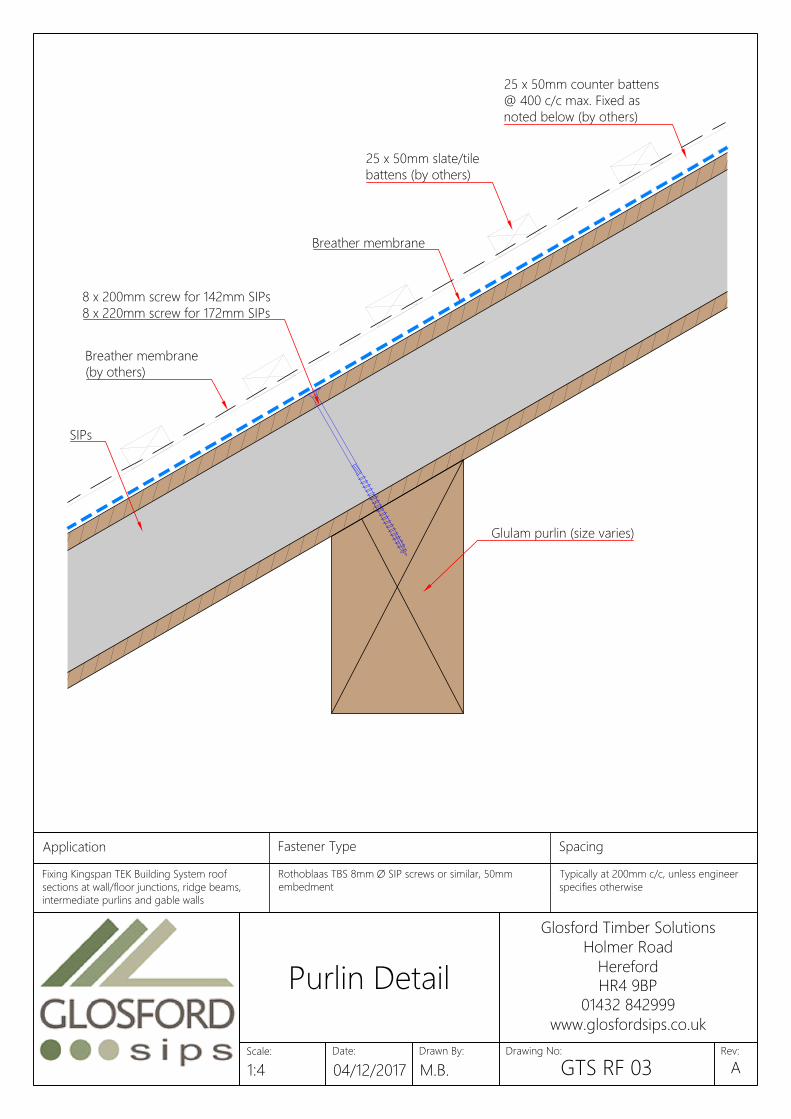
Breather membrane
25 x 50mm counter battens
@ 400 c/c max. Fixed as
noted below (by others)
25 x 50mm slate/tile
battens (by others)
SIPs
8 x 200mm screw for 142mm SIPs
8 x 220mm screw for 172mm SIPs
Glulam purlin (size varies)
Breather membrane
(by others)
Application Fastener Type Spacing
Specifications should be in accordance with project Fixing soleplate or combined soleplateFixing Kingspan TEK Building System roof
sections at wall/floor junctions, ridge beams,
intermediate purlins and gable walls
Rothoblaas TBS 8mm Ø SIP screws or similar, 50mm
embedment
Typically at 200mm c/c, unless engineer
specifies otherwise
Fixing joist hangers to headplate or laminated 3.75mm x 32mm square twist shank nails or Simpson N10 Into side and top of headplate locations
Date:
Glosford Timber Solutions
Holmer Road
Hereford
HR4 9BP
01432 842999
www.glosfordsips.co.uk
Scale: Drawn By: Drawing No: Rev:
Purlin Detail
1:4 04/12/2017 M.B. GTS RF 03A

silicone bead shown thus
Fillets (to engineers specification)
OSB Cover Strip
Fix SIP to fillet 3.1 x 63mm
nails @ 50mm c/c
8 x 140mm screw @ 400c/c.
Minimum embedment 50mm
into opposing timber
2no 100mm wide strips of
overlapping Rothoblaas Flexi
Band tape (or similar) to valley
Application Fastener Type Spacing
Specifications should be in accordance with project Fixing soleplate or combined soleplateFixing bottomplates, headplates, end timbers
and edge timbers into Kingspan TEK Building
System panels
3.1mm x 63mm galvanized ring-shank nails 50mm centres both sides of the panels
Fixing 100mm x 110 / 140mm insulated splines or 3.1mm x 63mm galvanized ring-shank nails 50mm centres both sides of the panelsFixing Kingspan TEK Building System roof
sections at wall/floor junctions, ridge beams,
intermediate purlins and gable walls
Rothoblaas TBS 8mm Ø SIP screws or similar, 50mm
embedment
Typically at 200mm c/c, unless engineer
specifies otherwise
Fixing joist hangers to headplate or laminated 3.75mm x 32mm square twist shank nails or Simpson N10 Into side and top of headplate locations
Date:
Glosford Timber Solutions
Holmer Road
Hereford
HR4 9BP
01432 842999
www.glosfordsips.co.uk
Scale: Drawn By: Drawing No: Rev:
Equal Valley Detail
1:4 04/12/2017 M.B. GTS RF 04A
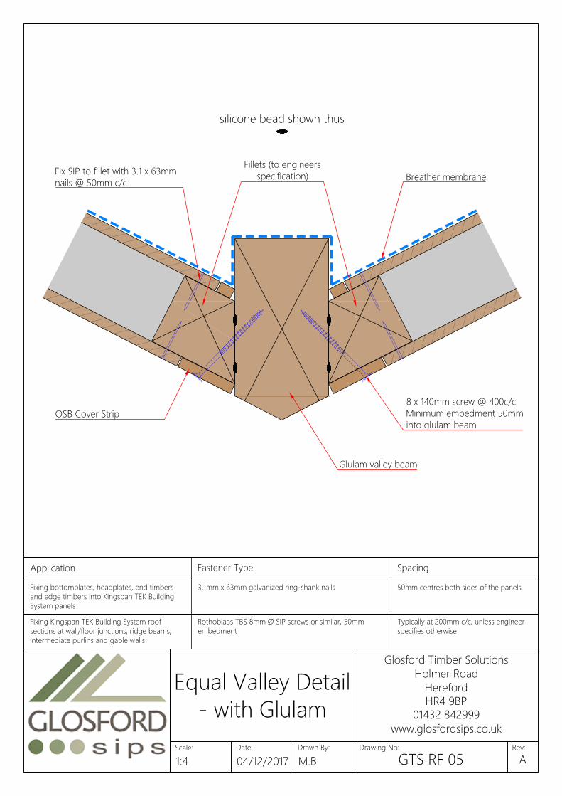
silicone bead shown thus
OSB Cover Strip
8 x 140mm screw @ 400c/c.
Minimum embedment 50mm
into glulam beam
Fillets (to engineers
specification)
Glulam valley beam
Fix SIP to fillet with 3.1 x 63mm
nails @ 50mm c/c
Breather membrane
Application Fastener Type Spacing
Specifications should be in accordance with project Fixing soleplate or combined soleplateFixing bottomplates, headplates, end timbers
and edge timbers into Kingspan TEK Building
System panels
3.1mm x 63mm galvanized ring-shank nails 50mm centres both sides of the panels
Fixing 100mm x 110 / 140mm insulated splines or 3.1mm x 63mm galvanized ring-shank nails 50mm centres both sides of the panelsFixing Kingspan TEK Building System roof
sections at wall/floor junctions, ridge beams,
intermediate purlins and gable walls
Rothoblaas TBS 8mm Ø SIP screws or similar, 50mm
embedment
Typically at 200mm c/c, unless engineer
specifies otherwise
Fixing joist hangers to headplate or laminated 3.75mm x 32mm square twist shank nails or Simpson N10 Into side and top of headplate locations
Date:
Glosford Timber Solutions
Holmer Road
Hereford
HR4 9BP
01432 842999
www.glosfordsips.co.uk
Scale: Drawn By: Drawing No: Rev:
Equal Valley Detail
- with Glulam
1:4 04/12/2017 M.B. GTS RF 05A

SIP
SIP
OSB cover strip
3.1 x 63mm nails
silicone bead
shown thus
OSB cover strip
Timber Fillet
SIP
Breather membrane
See Overlaid detail: GTS RF 07
8 x 200mm screw for 142mm SIPs
8 x 220mm screw for 172mm SIPs
8 x 140mm SIP screws @
200mm staggered centres
Application Fastener Type Spacing
Specifications should be in accordance with project Fixing soleplate or combined soleplateFixing bottomplates, headplates, end timbers
and edge timbers into Kingspan TEK Building
System panels
3.1mm x 63mm galvanized ring-shank nails 50mm centres both sides of the panels
Fixing 100mm x 110 / 140mm insulated splines or 3.1mm x 63mm galvanized ring-shank nails 50mm centres both sides of the panelsFixing Kingspan TEK Building System roof
sections at wall/floor junctions, ridge beams,
intermediate purlins and gable walls
Rothoblaas TBS 8mm Ø SIP screws or similar, 50mm
embedment
Typically at 200mm c/c, unless engineer
specifies otherwise
Fixing joist hangers to headplate or laminated 3.75mm x 32mm square twist shank nails or Simpson N10 Into side and top of headplate locations
Date:
Glosford Timber Solutions
Holmer Road
Hereford
HR4 9BP
01432 842999
www.glosfordsips.co.uk
Scale: Drawn By: Drawing No: Rev:
Dormer
1:20 04/12/2017 M.B. GTS RF 06A
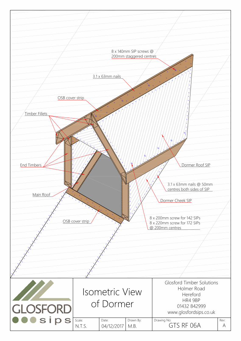
Main Roof
OSB cover strip
3.1 x 63mm nails
OSB cover strip
Dormer Cheek SIP
Timber Fillets
Dormer Roof SIP
8 x 140mm SIP screws @
200mm staggered centres
End Timbers
8 x 200mm screw for 142 SIPs
8 x 220mm screw for 172 SIPs
@ 200mm centres
3.1 x 63mm nails @ 50mm
centres both sides of SIP
Date:
Glosford Timber Solutions
Holmer Road
Hereford
HR4 9BP
01432 842999
www.glosfordsips.co.uk
Scale: Drawn By: Drawing No: Rev:
Isometric View
of Dormer
N.T.S. 04/12/2017 M.B. GTS RF 06AA
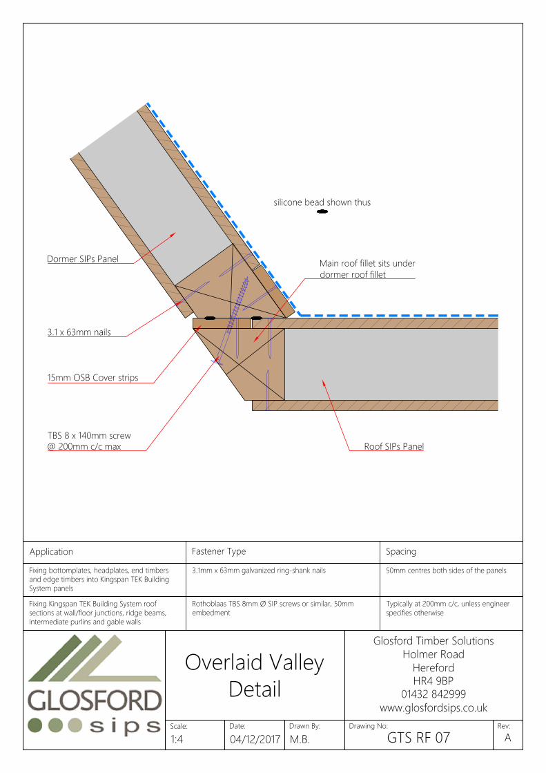
silicone bead shown thus
Main roof fillet sits under
dormer roof fillet
Dormer SIPs Panel
TBS 8 x 140mm screw
@ 200mm c/c max
15mm OSB Cover strips
3.1 x 63mm nails
Roof SIPs Panel
Application Fastener Type Spacing
Specifications should be in accordance with project Fixing soleplate or combined soleplateFixing bottomplates, headplates, end timbers
and edge timbers into Kingspan TEK Building
System panels
3.1mm x 63mm galvanized ring-shank nails 50mm centres both sides of the panels
Fixing 100mm x 110 / 140mm insulated splines or 3.1mm x 63mm galvanized ring-shank nails 50mm centres both sides of the panelsFixing Kingspan TEK Building System roof
sections at wall/floor junctions, ridge beams,
intermediate purlins and gable walls
Rothoblaas TBS 8mm Ø SIP screws or similar, 50mm
embedment
Typically at 200mm c/c, unless engineer
specifies otherwise
Fixing joist hangers to headplate or laminated 3.75mm x 32mm square twist shank nails or Simpson N10 Into side and top of headplate locations
Date:
Glosford Timber Solutions
Holmer Road
Hereford
HR4 9BP
01432 842999
www.glosfordsips.co.uk
Scale: Drawn By: Drawing No: Rev:
Overlaid Valley
Detail
1:4 04/12/2017 M.B. GTS RF 07A

X
X
X
*
XXX*: STRUCTURAL OPENING
Size to be confirmed by the
client, including any insulated
collars that sit in the roof depth.
XXX*
SIPs
Roof light and fixings (by others)
Roof cladding (by others)
Roof light and fixings (by others)
SIPs
Counter batten
(by others)
Date:
Glosford Timber Solutions
Holmer Road
Hereford
HR4 9BP
01432 842999
www.glosfordsips.co.uk
Scale: Drawn By: Drawing No: Rev:
Rooflight
1:10 04/12/2017 M.B. GTS RF 08A
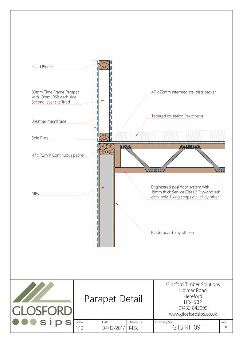
89mm Time Frame Parapet
with 10mm OSB each side
Second layer site fixed
SIPs
Plasterboard (by others)
Breather membrane
Sole Plate
Engineered posi floor system with
18mm thick Service Class 3 Plywood sub
deck only. Fixing straps etc. all by other.
Tapered Insulation (by others)
47 x 72mm Intermediate joists packer
Head Binder
47 x 72mm Continuous packer
Date:
Glosford Timber Solutions
Holmer Road
Hereford
HR4 9BP
01432 842999
www.glosfordsips.co.uk
Scale: Drawn By: Drawing No: Rev:
Parapet Detail
1:10 04/12/2017 M.B. GTS RF 09A

Lintel, as required by engineer
Slate/tiles and battens
(by others)
Proprietary cavity
closer (by others)
Trusses by Glosford. Centres and
timber sizes TBC in engineering
Soffit (by others)
Ventilation Cavity (25mm)
Insulation (by others)
Over Fascia
Ventilator
Roofing Underlay
(by others)
Head Binder
SIPs panel
2
5
Date:
Glosford Timber Solutions
Holmer Road
Hereford
HR4 9BP
01432 842999
www.glosfordsips.co.uk
Scale: Drawn By: Drawing No: Rev:
SIP with Truss
Roof
1:10 04/12/2017 M.B. GTS RF 10A
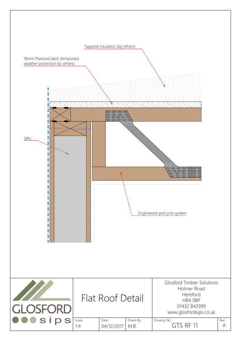
Engineered posi joist system
SIPs
Tapered insulation (by others)
18mm Plywood deck (temporary
weather protection by others)
Date:
Glosford Timber Solutions
Holmer Road
Hereford
HR4 9BP
01432 842999
www.glosfordsips.co.uk
Scale: Drawn By: Drawing No: Rev:
Flat Roof Detail
1:4 04/12/2017 M.B. GTS RF 11A
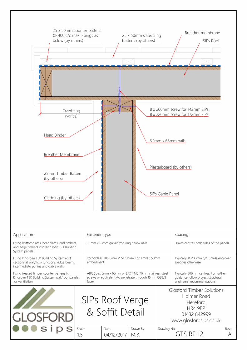
Breather Membrane
25mm Timber Batten
(by others)
Cladding (by others)
SIPs Roof
Plasterboard (by others)
SIPs Gable Panel
3.1mm x 63mm nails
Breather membrane
25 x 50mm counter battens
@ 400 c/c max. Fixings as
below (by others)
8 x 200mm screw for 142mm SIPs
8 x 220mm screw for 172mm SIPs
Head Binder
25 x 50mm slate/tiling
battens (by others)
Overhang
(varies)
Application Fastener Type Spacing
Specifications should be in accordance with project Fixing soleplate or combined soleplateFixing bottomplates, headplates, end timbers
and edge timbers into Kingspan TEK Building
System panels
3.1mm x 63mm galvanized ring-shank nails 50mm centres both sides of the panels
Fixing 100mm x 110 / 140mm insulated splines or 3.1mm x 63mm galvanized ring-shank nails 50mm centres both sides of the panelsFixing Kingspan TEK Building System roof
sections at wall/floor junctions, ridge beams,
intermediate purlins and gable walls
Rothoblaas TBS 8mm Ø SIP screws or similar, 50mm
embedment
Typically at 200mm c/c, unless engineer
specifies otherwise
Fixing joist hangers to headplate or laminated 3.75mm x 32mm square twist shank nails or Simpson N10 Into side and top of headplate locationsFixing treated timber counter battens to
Kingspan TEK Building System wall/roof panels
for ventilation
ABC Spax 5mm x 60mm or EJOT M5 70mm stainless steel
screws or equivalent (to penetrate through 15mm OSB/3
face)
Typically 300mm centres. For further
guidance follow project structural
engineers' recommendations
Fixing Timber Frame to Soleplate 3.1mm x 63mm galvanized ring-shank nails 200mm centres in two staggered rows
Date:
Glosford Timber Solutions
Holmer Road
Hereford
HR4 9BP
01432 842999
www.glosfordsips.co.uk
Scale: Drawn By: Drawing No: Rev:
SIPs Roof Verge
& Soffit Detail
1:5 04/12/2017 M.B. GTS RF 12A

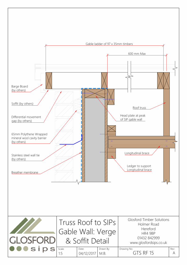
Gable ladder of 97 x 35mm timbers
600 mm Max
38 x 89mm Head Binder
Roof truss
65mm Polythene Wrapped
mineral wool cavity barrier
(by others)
Peak of timber frame panel (panel
consists of 38 x 89mm timbers)
15mm OSB Sheathing
Barge Board
(by others)
Soffit (by others)
Breather membrane
Differential movement
gap (by others)
Ledger to support
Longitudinal brace
Longitudinal brace
Stainless steel wall tie
(by others)
Date:
Glosford Timber Solutions
Holmer Road
Hereford
HR4 9BP
01432 842999
www.glosfordsips.co.uk
Scale: Drawn By: Drawing No: Rev:
Truss Roof to Timber
Frame Gable Wall:
Verge & Soffit Detail
1:5 04/12/2017 M.B. GTS RF 13A

600mm Max
38 x 89mm Head Binder
Peak of timber frame
panel (panel consists
of 38 x 89mm timbers)
15 mm OSB Sheathing
Ledger to support
Longitudinal brace
Roof truss
Longitudinal brace
Under cloak
(by others)
Compressive sealant
(by others)
65mm Polythene
Wrapped mineral wool
cavity barrier (by others)
Breather membrane
Stainless steel wall tie
(by others)
Date:
Glosford Timber Solutions
Holmer Road
Hereford
HR4 9BP
01432 842999
www.glosfordsips.co.uk
Scale: Drawn By: Drawing No: Rev:
Truss Roof to Timber
Frame Gable Wall:
Clipped Verge Detail
1:5 04/12/2017 M.B. GTS RF 14A
Gable ladder of 97 x 35mm timbers
600 mm Max
Roof truss
65mm Polythene Wrapped
mineral wool cavity barrier
(by others)
Barge Board
(by others)
Soffit (by others)
Breather membrane
Differential movement
gap (by others)
Longitudinal brace
Stainless steel wall tie
(by others)
Head plate at peak
of SIP gable wall
Ledger to support
Longitudinal brace
Date:
Glosford Timber Solutions
Holmer Road
Hereford
HR4 9BP
01432 842999
www.glosfordsips.co.uk
Scale: Drawn By: Drawing No: Rev:
Truss Roof to SIPs
Gable Wall: Verge
& Soffit Detail
1:5 04/12/2017 M.B. GTS RF 15A

600mm Max
Head plate at peak
of SIP gable wall
Ledger to support
Longitudinal brace
Roof truss
Longitudinal brace
Under cloak
(by others)
Compressive sealant
(by others)
65mm Polythene
Wrapped mineral wool
cavity barrier (by others)
Breather membrane
Stainless steel wall tie
(by others)
Date:
Glosford Timber Solutions
Holmer Road
Hereford
HR4 9BP
01432 842999
www.glosfordsips.co.uk
Scale: Drawn By: Drawing No: Rev:
Truss Roof to SIPs
Gable Wall: Clipped
Verge Detail
1:5 04/12/2017 M.B. GTS RF 16A
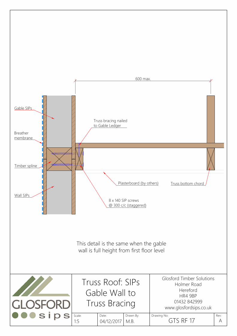
Gable SIPs
Wall SIPs
Timber spline
8 x 140 SIP screws
@ 300 c/c (staggered)
600 max.
Plasterboard (by others)
Truss bracing nailed
to Gable Ledger
Truss bottom chord
Breather
membrane
This detail is the same when the gable
wall is full height from first floor level
Date:
Glosford Timber Solutions
Holmer Road
Hereford
HR4 9BP
01432 842999
www.glosfordsips.co.uk
Scale: Drawn By: Drawing No: Rev:
Truss Roof: SIPs
Gable Wall to
Truss Bracing
1:5 04/12/2017 M.B. GTS RF 17A

7.5 Tolerance 7.5 Tolerance
Spans below 2.4m: 38x89mm joists at 400mm centres
Spans between 2.4 and 3.6 m wide: 38x140mm joists at 400mm centres
15mm OSB supplied loose, to be fitted on site.
Joist Direction
15
Fix infill panel to the SIP panel edge timber
with TBS ∅8.0x100 at 400mm max. centres
and at either end of ledger- end distance
for first TBS screw to be 100-150mm.
Roof SIPs
Roof SIPs
Date:
Glosford Timber Solutions
Holmer Road
Hereford
HR4 9BP
01432 842999
www.glosfordsips.co.uk
Scale: Drawn By: Drawing No: Rev:
SIPs Roof
Opening Infill
Panel
1:10 04/12/2017 M.B. GTS RF 18A

SIPs wall
2 x A35 Framing Anchor per
connection. All holes to be fixed
using square twisted sheradised nails.
Roof truss to Glosford
engineers specification
Date:
Glosford Timber Solutions
Holmer Road
Hereford
HR4 9BP
01432 842999
www.glosfordsips.co.uk
Scale: Drawn By: Drawing No: Rev:
Truss Roof
Connection to
SIPs Wall Detail
N.T.S. 04/12/2017 M.B. GTS RF 19A
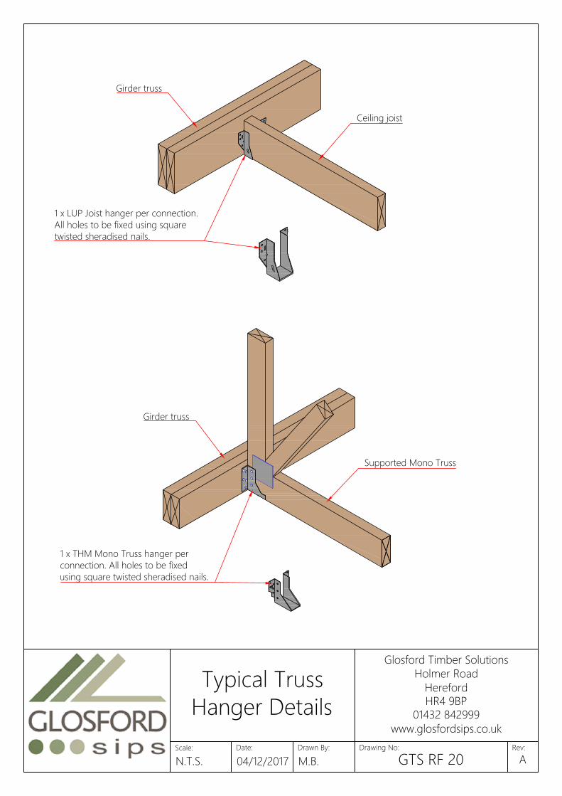
Girder truss
Ceiling joist
1 x LUP Joist hanger per connection.
All holes to be fixed using square
twisted sheradised nails.
Girder truss
Supported Mono Truss
1 x THM Mono Truss hanger per
connection. All holes to be fixed
using square twisted sheradised nails.
Date:
Glosford Timber Solutions
Holmer Road
Hereford
HR4 9BP
01432 842999
www.glosfordsips.co.uk
Scale: Drawn By: Drawing No: Rev:
Typical Truss
Hanger Details
N.T.S. 04/12/2017 M.B. GTS RF 20A

Supported truss
Girder truss
THA truss shoes. All holes to
be fixed using long square
twisted sheradised nails
Supported girder truss
Girder truss
HGUS truss shoes. All holes to be
fixed using long square twisted
sheradised nails. Nails must be driven
at an angle through the truss into the
carrying member to achieve full fixing.
Date:
Glosford Timber Solutions
Holmer Road
Hereford
HR4 9BP
01432 842999
www.glosfordsips.co.uk
Scale: Drawn By: Drawing No: Rev:
Typical Truss
Hanger Details 2
N.T.S. 04/12/2017 M.B. GTS RF 21A

1 x TCP38/47/50 Truss Clip
per connection. All holes to
be fixed using square
twisted sheradised nails.
SIPs wall
Roof truss - profile determined
by Glosford engineer
Date:
Glosford Timber Solutions
Holmer Road
Hereford
HR4 9BP
01432 842999
www.glosfordsips.co.uk
Scale: Drawn By: Drawing No: Rev:
Truss Roof
Connection to
SIPs Wall Detail
N.T.S. 04/12/2017 M.B. GTS RF 22A

2no 47 x 147mm TR26 Header
Ridgeboard propped by
47 x 97mm Gable panel
1no 35 x 147mm TR26 Ridgeboard
2no 22 x 147mm
Layboards
47 x 97mm
Dormer cheeks
35 x 97mm TR26 Joists
35 x 97mm TR26 Rafters
Timber sizes shown are
typical and should be
checked for each project
SIPs wall
Brick cladding (by others)
Date:
Glosford Timber Solutions
Holmer Road
Hereford
HR4 9BP
01432 842999
www.glosfordsips.co.uk
Scale: Drawn By: Drawing No: Rev:
Truss Roof: Attic
Dormer Roof
Construction Detail
N.T.S. 04/12/2017 M.B. GTS RF 23A

Timber sizes shown are
typical and should be
checked for each project
1no 35 x 147mm TR26 Ridgeboard
35 x 97mm TR26 Joists
35 x 97mm TR26 Rafters
2no 22 x 147mm Layboards
47 x 97mm Dormer cheeks
SIPs wall
Brick cladding (by others)
2no 47 x 147mm
TR26 Header
Ridgeboard propped by
47 x 97mm Gable panel
Date:
Glosford Timber Solutions
Holmer Road
Hereford
HR4 9BP
01432 842999
www.glosfordsips.co.uk
Scale: Drawn By: Drawing No: Rev:
Truss Roof: Raised
Dormer Roof
Construction Detail
N.T.S. 04/12/2017 M.B. GTS RF 24A

3
0
0
35 x 72mm
TR26 Noggins
25 x 35/47 x 300mm long
timber fixed to rafter with
3.1 x 75mm long
galvanised wire nails
Tiling batten fixed
between each frame
Date:
Glosford Timber Solutions
Holmer Road
Hereford
HR4 9BP
01432 842999
www.glosfordsips.co.uk
Scale: Drawn By: Drawing No: Rev:
Truss Roof: Valley
Frame Construction
Detail
N.T.S. 04/12/2017 M.B. GTS RF 25A
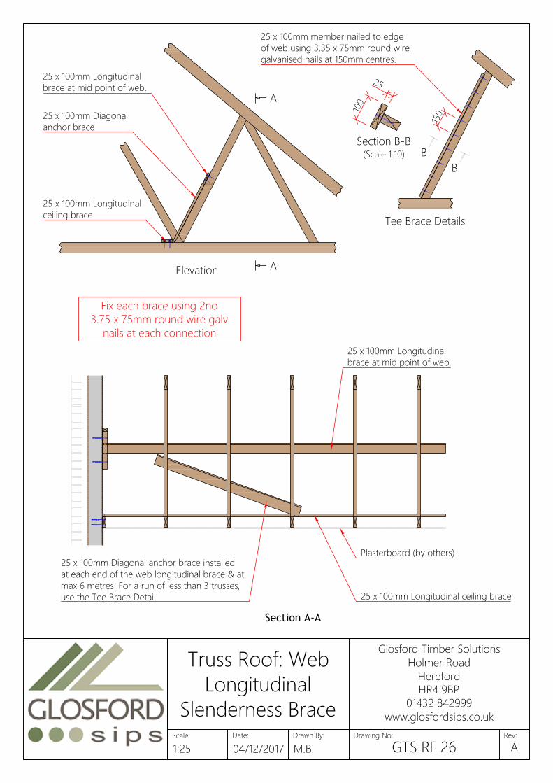
Elevation
Section A-A
25 x 100mm Diagonal
anchor brace
25 x 100mm Longitudinal
brace at mid point of web.
25 x 100mm Longitudinal
ceiling brace
25 x 100mm Longitudinal ceiling brace
25 x 100mm Diagonal anchor brace installed
at each end of the web longitudinal brace & at
max 6 metres. For a run of less than 3 trusses,
use the Tee Brace Detail
25 x 100mm Longitudinal
brace at mid point of web.
Fix each brace using 2no
3.75 x 75mm round wire galv
nails at each connection
A
Tee Brace Details
B
B
A
25 x 100mm member nailed to edge
of web using 3.35 x 75mm round wire
galvanised nails at 150mm centres.
Section B-B
(Scale 1:10)
2
5
1
0
0
Plasterboard (by others)
1
5
0
Date:
Glosford Timber Solutions
Holmer Road
Hereford
HR4 9BP
01432 842999
www.glosfordsips.co.uk
Scale: Drawn By: Drawing No: Rev:
Truss Roof: Web
Longitudinal
Slenderness Brace
1:25 04/12/2017 M.B. GTS RF 26A
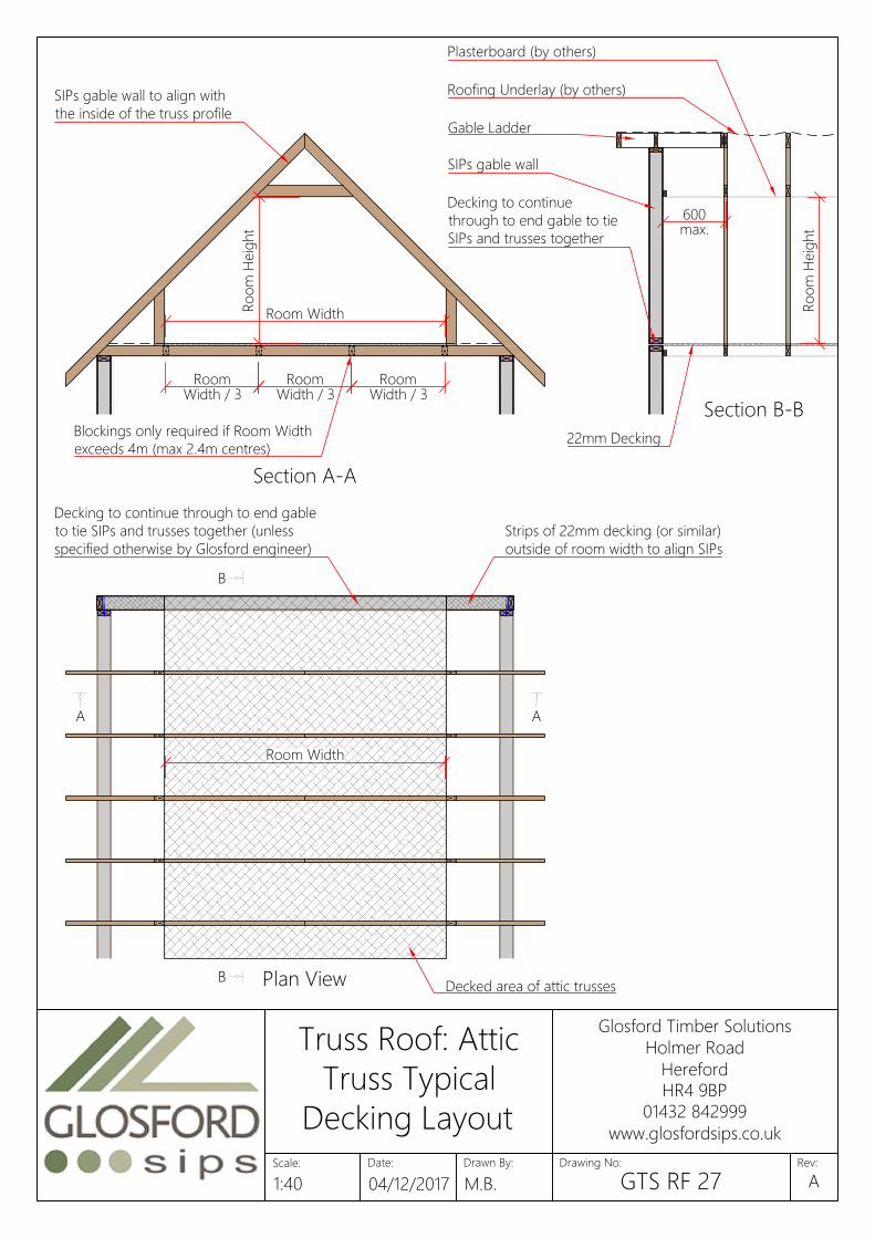
Ro
om
H
eig
ht
Room Width
Room
Width / 3
Room
Width / 3
Room
Width / 3
Blockings only required if Room Width
exceeds 4m (max 2.4m centres)
Room Width
Ro
om
H
eig
ht
600
max.
Decking to continue
through to end gable to tie
SIPs and trusses together
SIPs gable wall
Plasterboard (by others)
Roofing Underlay (by others)
Gable Ladder
Decking to continue through to end gable
to tie SIPs and trusses together (unless
specified otherwise by Glosford engineer)
Strips of 22mm decking (or similar)
outside of room width to align SIPs
SIPs gable wall to align with
the inside of the truss profile
Section A-A
Section B-B
Plan View
AA
B
B
22mm Decking
Decked area of attic trusses
Date:
Glosford Timber Solutions
Holmer Road
Hereford
HR4 9BP
01432 842999
www.glosfordsips.co.uk
Scale: Drawn By: Drawing No: Rev:
Truss Roof: Attic
Truss Typical
Decking Layout
1:40 04/12/2017 M.B. GTS RF 27A

8 x 200mm screw to fix SIPs to Purlin (142 SIPs)
8 x 220mm screw to fix SIPs to Purlin (172 SIPs)
@ 200mm staggered centres
8 x 140mm screw to fix SIPs together
@ 200mm staggered centres
OSB cover strip
Glulam ridge beam to Glosfords
engineers specification
100 x 108mm timber spline (142 SIPs)
80 x 138mm timber spline (172 SIPs)3.1 x 63mm smooth nails @ 50mm
centres to both side of the panel
Roof SIPs fixed to profiled
timber wall plate
Roof SIPs end timber plumb and seatcut
to allow for fascia and soffit boards
Structural opening for rooflight. Timber
sizes to Glosfords engineers specification
8 x 200mm TBS screw (142 SIPs)
8 x 220mm TBS screw (172 SIPs)
@ 200mm centres
Date:
Glosford Timber Solutions
Holmer Road
Hereford
HR4 9BP
01432 842999
www.glosfordsips.co.uk
Scale: Drawn By: Drawing No: Rev:
Isometric View
of SIPs Roof
Construction
N.T.S. 04/12/2017 M.B. GTS RF 28A

Breather membrane
Oak frame (by others)
8mm screw, 50mm min
embedment into oak frame
450mm wide 500
gauge polythene DPC
Continuous packer nailed
or screwed to Oak frame
(size varies)
Plasterboard and
battens (by others)
Application Fastener Type Spacing
Specifications should be in accordance with project Fixing soleplate or combined soleplateFixing Kingspan TEK Building System to oak
timber framing
Rothoblaas TBS 8mm Ø SIP screws or similar, 50mm
embedment into oak
Typically at 400mm c/c, unless engineer
specifies otherwise
Fixing Timber Frame Party Wall Panels to Glulam x 160mm SIP screws or similar Typically at 600mm c/c, unless engineer
Date:
Glosford Timber Solutions
Holmer Road
Hereford
HR4 9BP
01432 842999
www.glosfordsips.co.uk
Scale: Drawn By: Drawing No: Rev:
Oak Post Detail
1:5 04/12/2017 M.B. GTS OF 01A
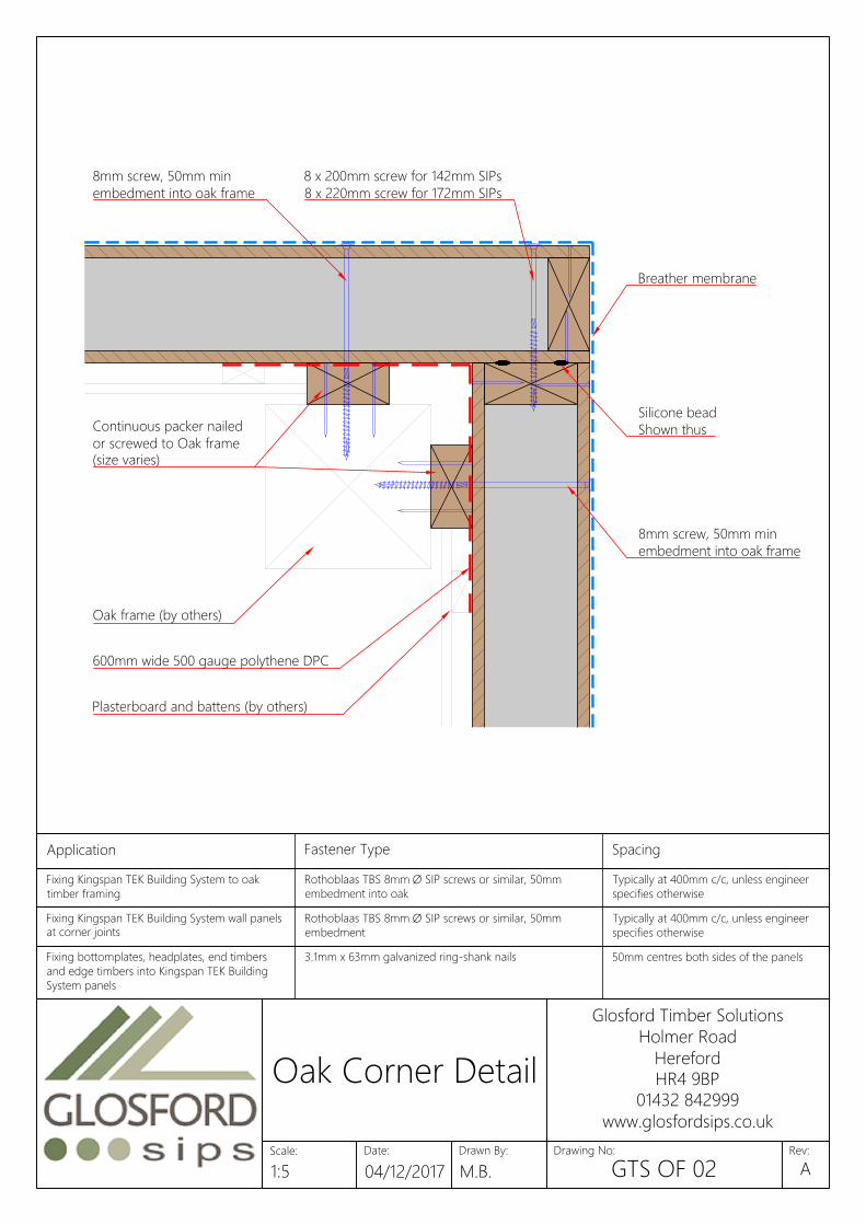
8mm screw, 50mm min
embedment into oak frame
Oak frame (by others)
Breather membrane
8 x 200mm screw for 142mm SIPs
8 x 220mm screw for 172mm SIPs
Silicone bead
Shown thus
8mm screw, 50mm min
embedment into oak frame
600mm wide 500 gauge polythene DPC
Continuous packer nailed
or screwed to Oak frame
(size varies)
Plasterboard and battens (by others)
Fixing bottomplates, headplates, end timbers
and edge timbers into Kingspan TEK Building
System panels
3.1mm x 63mm galvanized ring-shank nails 50mm centres both sides of the panels
Fixing 100mm x 110 / 140mm insulated splines or 3.1mm x 63mm galvanized ring-shank nails 50mm centres both sides of the panels
Fixing Kingspan TEK Building System wall panels
at corner joints
Rothoblaas TBS 8mm Ø SIP screws or similar, 50mm
embedment
Typically at 400mm c/c, unless engineer
specifies otherwise
Fixing Kingspan TEK Building System roof SIP screws or similar, 50mm Typically at 200mm c/c, unless engineer
Application Fastener Type Spacing
Specifications should be in accordance with project Fixing soleplate or combined soleplateFixing Kingspan TEK Building System to oak
timber framing
Rothoblaas TBS 8mm Ø SIP screws or similar, 50mm
embedment into oak
Typically at 400mm c/c, unless engineer
specifies otherwise
Fixing Timber Frame Party Wall Panels to Glulam x 160mm SIP screws or similar Typically at 600mm c/c, unless engineer
Date:
Glosford Timber Solutions
Holmer Road
Hereford
HR4 9BP
01432 842999
www.glosfordsips.co.uk
Scale: Drawn By: Drawing No: Rev:
Oak Corner Detail
1:5 04/12/2017 M.B. GTS OF 02A
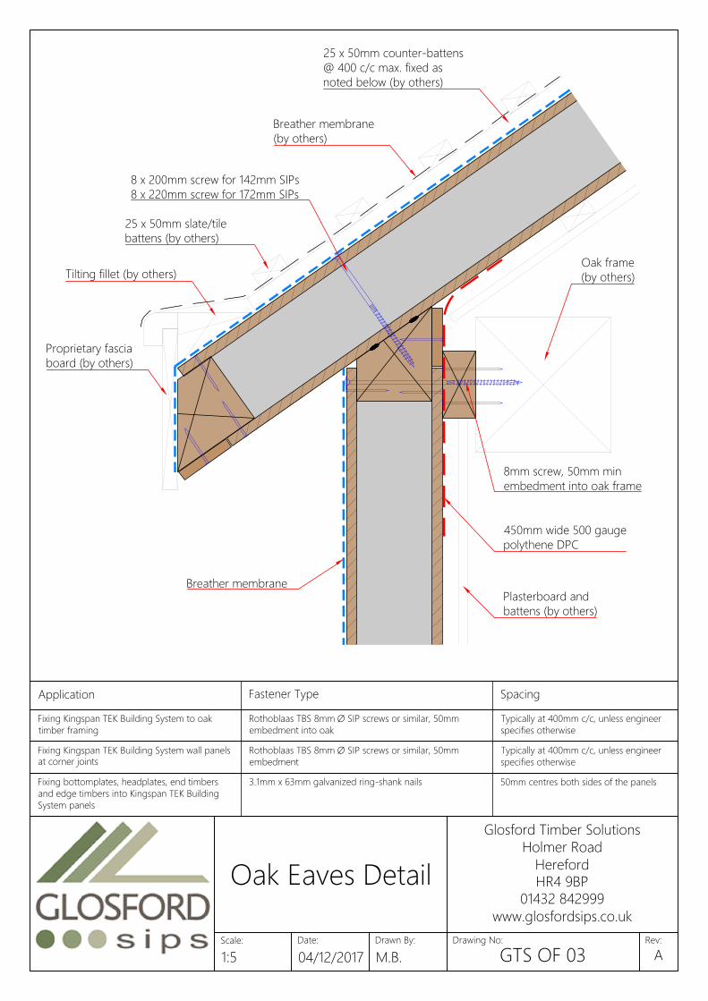
Oak frame
(by others)
Breather membrane
450mm wide 500 gauge
polythene DPC
Plasterboard and
battens (by others)
8 x 200mm screw for 142mm SIPs
8 x 220mm screw for 172mm SIPs
Breather membrane
(by others)
25 x 50mm counter-battens
@ 400 c/c max. fixed as
noted below (by others)
25 x 50mm slate/tile
battens (by others)
Tilting fillet (by others)
Proprietary fascia
board (by others)
8mm screw, 50mm min
embedment into oak frame
Fixing bottomplates, headplates, end timbers
and edge timbers into Kingspan TEK Building
System panels
3.1mm x 63mm galvanized ring-shank nails 50mm centres both sides of the panels
Fixing 100mm x 110 / 140mm insulated splines or 3.1mm x 63mm galvanized ring-shank nails 50mm centres both sides of the panels
Fixing Kingspan TEK Building System wall panels
at corner joints
Rothoblaas TBS 8mm Ø SIP screws or similar, 50mm
embedment
Typically at 400mm c/c, unless engineer
specifies otherwise
Fixing Kingspan TEK Building System roof SIP screws or similar, 50mm Typically at 200mm c/c, unless engineer
Application Fastener Type Spacing
Specifications should be in accordance with project Fixing soleplate or combined soleplateFixing Kingspan TEK Building System to oak
timber framing
Rothoblaas TBS 8mm Ø SIP screws or similar, 50mm
embedment into oak
Typically at 400mm c/c, unless engineer
specifies otherwise
Fixing Timber Frame Party Wall Panels to Glulam x 160mm SIP screws or similar Typically at 600mm c/c, unless engineer
Date:
Glosford Timber Solutions
Holmer Road
Hereford
HR4 9BP
01432 842999
www.glosfordsips.co.uk
Scale: Drawn By: Drawing No: Rev:
Oak Eaves Detail
1:5 04/12/2017 M.B. GTS OF 03A

Breather membrane
Oak purlin (by others)
8mm screw, 50mm min
embedment into oak frame
450mm wide, 500 gauge
polythene DPC
Continuous packer nailed
or screwed to Oak frame
(size varies)
Plasterboard and battens
(by others)
Fixing bottomplates, headplates, end timbers
and edge timbers into Kingspan TEK Building
System panels
3.1mm x 63mm galvanized ring-shank nails 50mm centres both sides of the panels
Fixing 100mm x 110 / 140mm insulated splines or 3.1mm x 63mm galvanized ring-shank nails 50mm centres both sides of the panels
Fixing Kingspan TEK Building System roof
sections at wall/floor junctions, ridge beams,
intermediate purlins and gable walls
Rothoblaas TBS 8mm Ø SIP screws or similar, 50mm
embedment
Typically at 200mm c/c, unless engineer
specifies otherwise
Fixing joist hangers to headplate or laminated 3.75mm x 32mm square twist shank nails or Simpson N10 Into side and top of headplate locations
Application Fastener Type Spacing
Specifications should be in accordance with project Fixing soleplate or combined soleplateFixing Kingspan TEK Building System to oak
timber framing
Rothoblaas TBS 8mm Ø SIP screws or similar, 50mm
embedment into oak
Typically at 400mm c/c, unless engineer
specifies otherwise
Fixing Timber Frame Party Wall Panels to Glulam x 160mm SIP screws or similar Typically at 600mm c/c, unless engineer
Date:
Glosford Timber Solutions
Holmer Road
Hereford
HR4 9BP
01432 842999
www.glosfordsips.co.uk
Scale: Drawn By: Drawing No: Rev:
Oak Purlin Detail
1:5 04/12/2017 M.B. GTS OF 04A
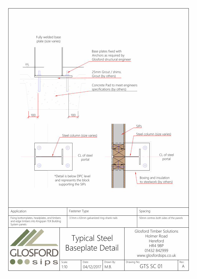
FFL
Fully welded base
plate (size varies)
CL of steel
portal
*Detail is below DPC level
and represents the block
supporting the SIPs
CL of steel
portal
Steel column (size varies)
25mm Grout / shims.
Grout (by others)
Concrete Pad to meet engineers
specifications (by others)
100 100
Base plates fixed with
Anchors as required by
Glosford structural engineer
Steel column (size varies)
Boxing and insulation
to steelwork (by others)
SIPs
Fixing bottomplates, headplates, end timbers
and edge timbers into Kingspan TEK Building
System panels
3.1mm x 63mm galvanized ring-shank nails 50mm centres both sides of the panels
Fixing 100mm x 110 / 140mm insulated splines or 3.1mm x 63mm galvanized ring-shank nails 50mm centres both sides of the panels
Application Fastener Type Spacing
Specifications should be in accordance with project Fixing soleplate or combined soleplate
Date:
Glosford Timber Solutions
Holmer Road
Hereford
HR4 9BP
01432 842999
www.glosfordsips.co.uk
Scale: Drawn By: Drawing No: Rev:
Typical Steel
Baseplate Detail
1:10 04/12/2017 M.B. GTS SC 01A

8mm x 140mm screw @ 200c/c
RHS Steel Wall Support
Roof SIPs
Brick External Leaf (by others)
Wall SIPs
For floor/wall details, see
drawing GTS FL 01
Date:
Glosford Timber Solutions
Holmer Road
Hereford
HR4 9BP
01432 842999
www.glosfordsips.co.uk
Scale: Drawn By: Drawing No: Rev:
Brickwork Steel
Support Detail
1:5 04/12/2017 M.B. GTS SC 02A
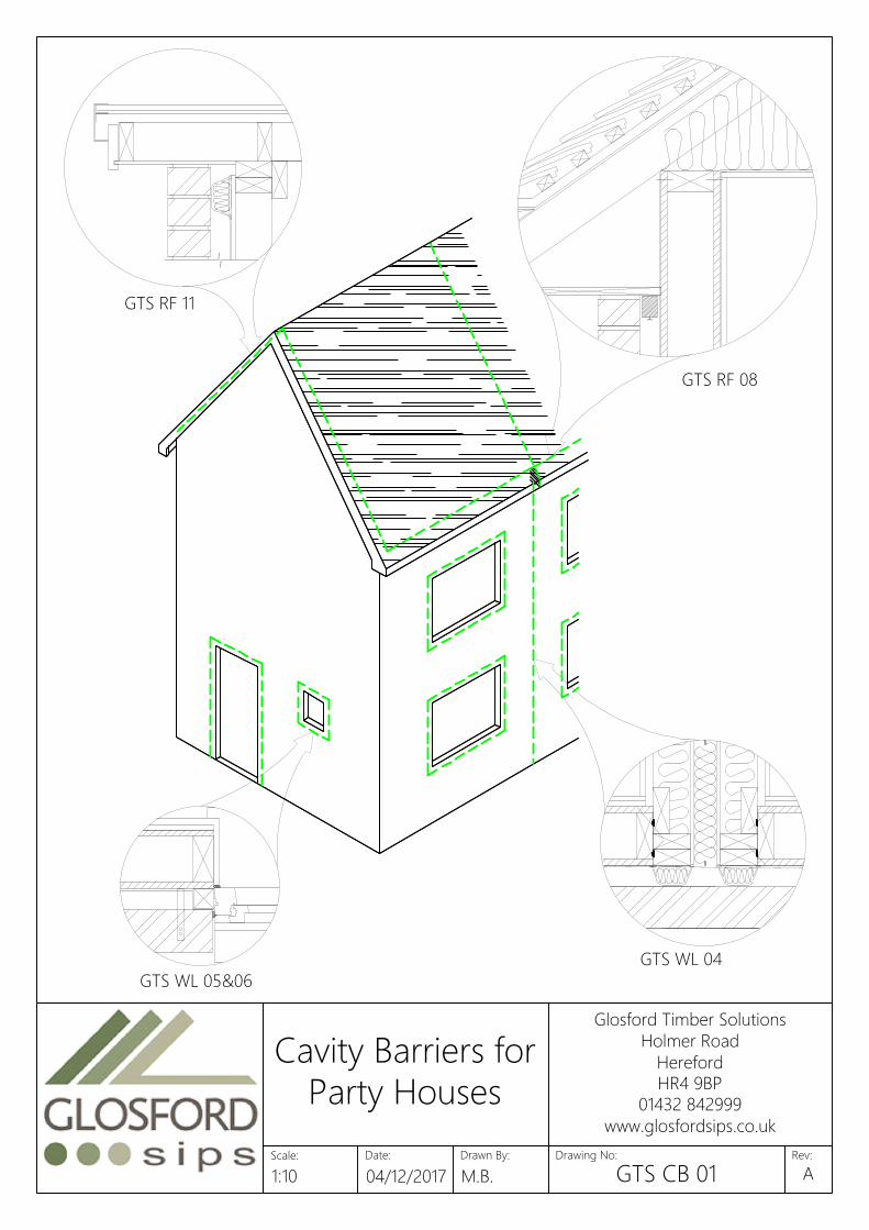
GTS WL 04
GTS RF 08
GTS WL 05&06
GTS RF 11
Date:
Glosford Timber Solutions
Holmer Road
Hereford
HR4 9BP
01432 842999
www.glosfordsips.co.uk
Scale: Drawn By: Drawing No: Rev:
Cavity Barriers for
Party Houses
1:10 04/12/2017 M.B. GTS CB 01A
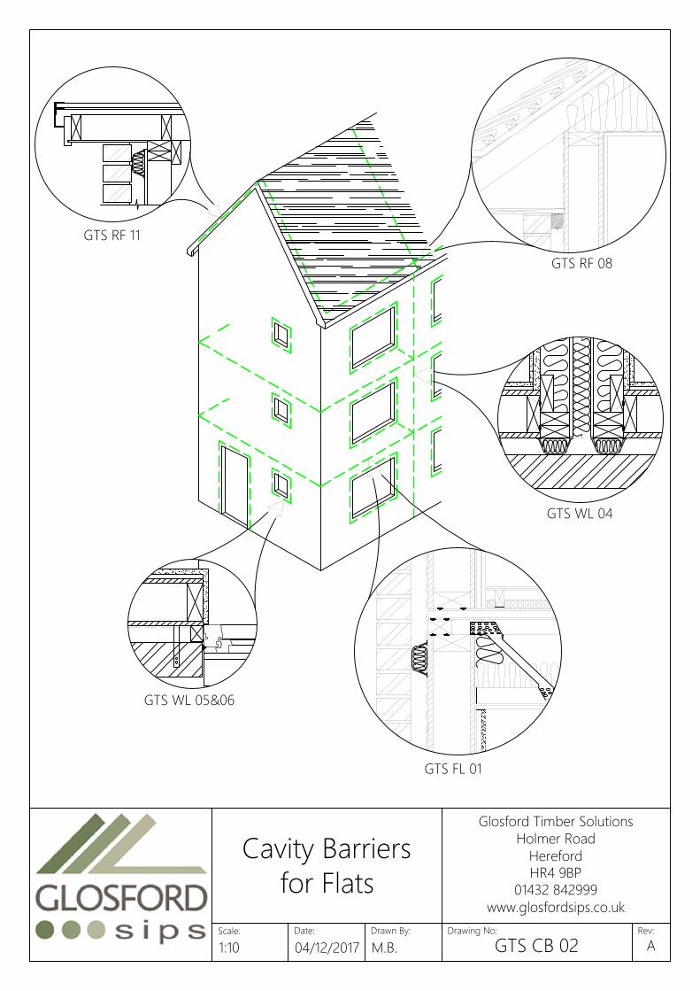
GTS WL 05&06
GTS FL 01
GTS WL 04
GTS RF 08
GTS RF 11
Date:
Glosford Timber Solutions
Holmer Road
Hereford
HR4 9BP
01432 842999
www.glosfordsips.co.uk
Scale: Drawn By: Drawing No: Rev:
Cavity Barriers
for Flats
1:10 04/12/2017 M.B. GTS CB 02A

0.15 W/m²K
P
l
a
s
t
e
r
b
o
a
r
d
2
5
m
m
T
i
m
b
e
r
B
a
t
t
e
n
(
o
p
t
i
o
n
a
l
)
T
h
e
r
m
a
w
a
l
l
T
W
5
5
*
*
o
r
s
i
m
i
l
a
r
S
I
P
s
P
a
n
e
l
*
B
r
e
a
t
h
i
n
g
M
e
m
b
r
a
n
e
5
0
m
m
C
a
v
i
t
y
B
r
i
c
k
C
l
a
d
d
i
n
g
None
20 mm
25 mm
30 mm
40 mm
50 mm
60 mm
70 mm
80 mm
90 mm
100 mm
0.19 W/m²K
0.15 W/m²K
0.14 W/m²K
0.13 W/m²K
0.12 W/m²K
0.12 W/m²K
0.11 W/m²K
0.11 W/m²K
0.10 W/m²K
0.10 W/m²K
0.13 W/m²K
0.16 W/m²K
0.12 W/m²K
0.12 W/m²K
0.11 W/m²K
0.11 W/m²K
0.10 W/m²K
Values calculated at www.uvalue-calculator.co.uk
Values calculated with brickwork cladding
and standard breathing membrane
**
Thermapitch
* SIPs
142mm 172mm
Date:
Glosford Timber Solutions
Holmer Road
Hereford
HR4 9BP
01432 842999
www.glosfordsips.co.uk
Scale: Drawn By: Drawing No: Rev:
Brick Cladding
Detail: U-Value
Options
1:10 04/12/2017 M.B. GTS UV 01A
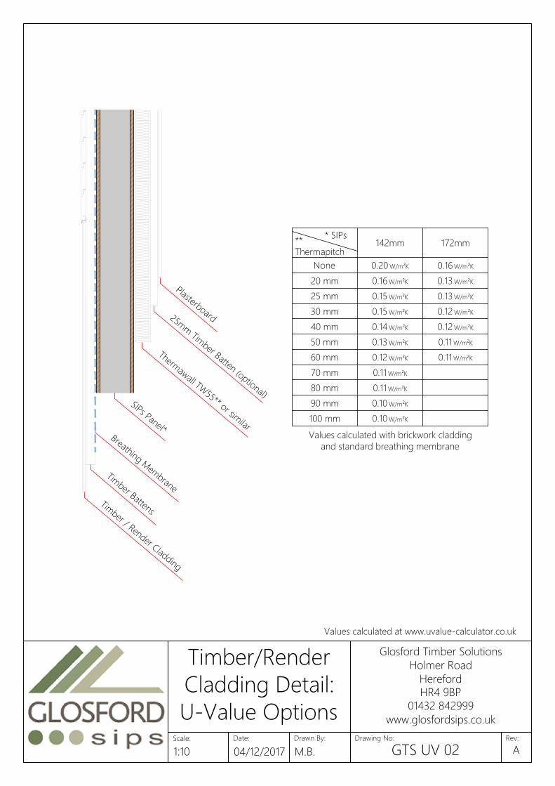
40 mm
P
l
a
s
t
e
r
b
o
a
r
d2
5
m
m
T
i
m
b
e
r
B
a
t
t
e
n
(
o
p
t
i
o
n
a
l
)
T
h
e
r
m
a
w
a
l
l
T
W
5
5
*
*
o
r
s
i
m
i
l
a
r
S
I
P
s
P
a
n
e
l
*
B
r
e
a
t
h
i
n
g
M
e
m
b
r
a
n
e
T
i
m
b
e
r
B
a
t
t
e
n
s
T
i
m
b
e
r
/
R
e
n
d
e
r
C
l
a
d
d
i
n
g
None
20 mm
25 mm
30 mm
50 mm
60 mm
80 mm
70 mm
90 mm
0.20 W/m²K
100 mm
0.16 W/m²K
0.15 W/m²K
0.15 W/m²K
0.14 W/m²K
0.13 W/m²K
0.12 W/m²K
0.11 W/m²K
0.11 W/m²K
0.10 W/m²K
Values calculated at www.uvalue-calculator.co.uk
0.10 W/m²K
0.13 W/m²K
0.16 W/m²K
0.13 W/m²K
0.12 W/m²K
0.12 W/m²K
0.11 W/m²K
0.11 W/m²K
Values calculated with brickwork cladding
and standard breathing membrane
**
Thermapitch
* SIPs
142mm 172mm
Date:
Glosford Timber Solutions
Holmer Road
Hereford
HR4 9BP
01432 842999
www.glosfordsips.co.uk
Scale: Drawn By: Drawing No: Rev:
Timber/Render
Cladding Detail:
U-Value Options
1:10 04/12/2017 M.B. GTS UV 02A
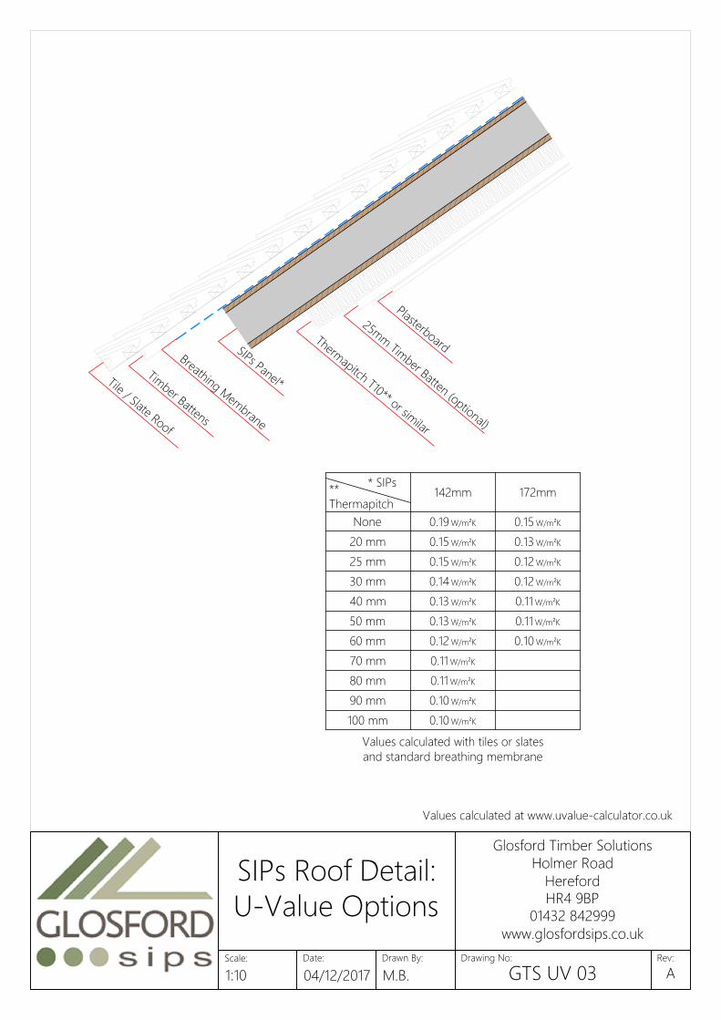
P
l
a
s
t
e
r
b
o
a
r
d
T
h
e
r
m
a
p
i
t
c
h
T
1
0
*
*
o
r
s
i
m
i
l
a
r
2
5
m
m
T
i
m
b
e
r
B
a
t
t
e
n
(
o
p
t
i
o
n
a
l
)
S
I
P
s
P
a
n
e
l
*
B
r
e
a
t
h
i
n
g
M
e
m
b
r
a
n
e
T
i
m
b
e
r
B
a
t
t
e
n
s
T
i
l
e
/
S
l
a
t
e
R
o
o
f
172mm
**
Thermapitch
* SIPs
142mm
None
20 mm
25 mm
30 mm
40 mm
50 mm
60 mm
70 mm
80 mm
90 mm
100 mm
0.19 W/m²K
0.15 W/m²K
0.15 W/m²K
0.14 W/m²K
0.13 W/m²K
0.13 W/m²K
0.12 W/m²K
0.11 W/m²K
0.11 W/m²K
0.10 W/m²K
0.10 W/m²K
0.13 W/m²K
0.15 W/m²K
0.12 W/m²K
0.12 W/m²K
0.11 W/m²K
0.11 W/m²K
0.10 W/m²K
Values calculated with tiles or slates
and standard breathing membrane
Values calculated at www.uvalue-calculator.co.uk
Date:
Glosford Timber Solutions
Holmer Road
Hereford
HR4 9BP
01432 842999
www.glosfordsips.co.uk
Scale: Drawn By: Drawing No: Rev:
SIPs Roof Detail:
U-Value Options
1:10 04/12/2017 M.B. GTS UV 03A