standard and high density d-sub - konmekkonmek.com/pdf/konmek_density_d-sub_catalog.pdf · page 4...
TRANSCRIPT

page 3
© Konmek Inc. All rights reserved. Document Revision 2016-04-19 - Specifications and drawings is subject to change, please consult factory for latest data - For more details visit www.konmek.com
Standard Density High Density
Material Data
Insulator Polyester GF UL94V-0
Insulator color
Contacts Precision machined copper alloy
Contact plating Hard Gold plated over Nickel
Shell Steel, dimples on Male shell
Shell plating Tin plated over Nickel or Nickel plating
Electrical Data
Current rating (at room temp) 5.0 A 3.0 A
Working Voltage 125 V 60 V
Dielectric strenght / Test Voltage Contact - contact 1000 V r.m.s.
Contact resistance < 10mΩ
Insulation resistance >5GΩ
Mechanical Data
Creepage distance 1.0mm 0.6mm
Operating Temperature Temp -55°C to +125°C
Quality Class Quality Class 1 = 500 Mating Cycles, 30μ” (0.8μm) Gold over Nickel)Quality Class 3 = 50 Mating Cycles 8μ” (0.2μm) Gold over Nickel
For other plating alternatves contact factory
Standard and High Density D-Sub
Tech Spec
Standard Density
High Density
The Standard Density D-Sub is the original D-Sub created some 50 years ago, the Standard Density D-Sub have signal contacts with current rating of 5A. There are 5 sizes with connector mating layouts ranging from 9 positions to 50 positions. This connector is widely used in industrial applications worldwide.
The High Density D-Sub have the same size as the Standard Density connector but hold more contacts in its insulator. For a Standard Density 9 position connector the High Density holds 15 positions, for a 15 position Standard Density connector, the High Density holds 26 positions, and so on, see Tech Specs for more details. The High Density connector have a drawback in comparison and that is the current rating which is only 3Aas the Standard Density have 5A . *62pos and 78pos have differ-ent pitch.pitch 2.29mm (2.41mm)*
3 Rowspitch 1.98mm
pitch 2.54mm
2 Rowspitch 2.84mm
KD
KH

page 4
© Konmek Inc. All rights reserved. Document Revision 2016-04-19 - Specifications and drawings is subject to change, please consult factory for latest data - For more details visit www.konmek.com
Standard Density High Density
Size 1(E)
9 pos 15 pos
Size 2(A)
15 pos 26 pos
Size 3(B)
25 pos 44 pos
Size 4(C)
37 pos 62 pos
Size 5(D)
50 pos 78 pos
Standard and High Density D-Sub
LayoutKD
KH

page 5
© Konmek Inc. All rights reserved. Document Revision 2016-04-19 - Specifications and drawings is subject to change, please consult factory for latest data - For more details visit www.konmek.com
Male
Drawing
Female
No. of pos. A B C D E
09 30.80 25.00 16.90 12.50 8.30
15 39.20 33.30 25.25 12.50 8.30
25 53.05 47.05 38.95 12.50 8.30
37 69.40 63.50 55.40 12.50 8.30
50 67.00 61.00 52.80 15.30 11.15
No. of pos. A B C D E
09 30.80 25.00 16.30 12.50 7.90
15 39.20 33.30 24.60 12.50 7.90
25 53.05 47.05 38.40 12.50 7.90
37 69.40 63.50 54.80 12.50 7.90
50 67.00 61.00 52.20 15.30 10.90
Part Number Code
KD S 4 -15 M T B A1Series:KD = Standard Density D-Sub
Mounting*:A1 = Mounting holeB1 = B1 with 4-40 UNCB6 = B6 with M3
Insulator color:B = Black (standard) W = White G = Green L = Blue
Gender:M = Male F = Female
Shell plating*:T = Tin (standard) N = Nickel
Terminal type:S = Solder cup
Contact plating*:4 = Quality Class 3 (standard)3 = Quality Class 1
Number of positions:09 = 9 pos 15 = 15 pos 25 = 25 pos37 = 37 pos 50 = 50 pos
See mounting drawings below for more details
Standard Density KD Series
Solder cupKD

page 6
© Konmek Inc. All rights reserved. Document Revision 2016-04-19 - Specifications and drawings is subject to change, please consult factory for latest data - For more details visit www.konmek.com
A1 B1/B6
Standard Density KD Series
Solder cup Mounting KD
page 7
© Konmek Inc. All rights reserved. Document Revision 2016-04-19 - Specifications and drawings is subject to change, please consult factory for latest data - For more details visit www.konmek.com
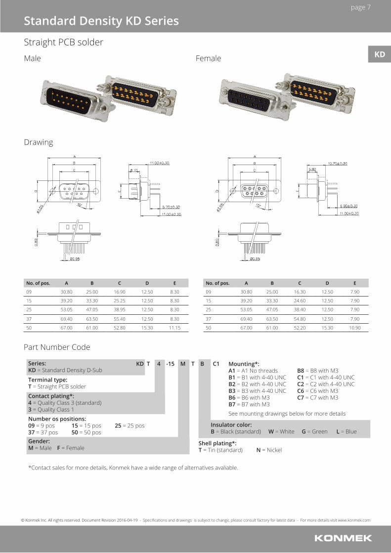
No. of pos. A B C D E
09 30.80 25.00 16.90 12.50 8.30
15 39.20 33.30 25.25 12.50 8.30
25 53.05 47.05 38.95 12.50 8.30
37 69.40 63.50 55.40 12.50 8.30
50 67.00 61.00 52.80 15.30 11.15
No. of pos. A B C D E
09 30.80 25.00 16.30 12.50 7.90
15 39.20 33.30 24.60 12.50 7.90
25 53.05 47.05 38.40 12.50 7.90
37 69.40 63.50 54.80 12.50 7.90
50 67.00 61.00 52.20 15.30 10.90
KD T 4 -15 M T B C1Series:KD = Standard Density D-Sub
Mounting*:A1 = A1 No threadsB1 = B1 with 4-40 UNCB2 = B2 with 4-40 UNCB3 = B3 with 4-40 UNCB6 = B6 with M3 B7 = B7 with M3
See mounting drawings below for more details
B8 = B8 with M3C1 = C1 with 4-40 UNC C2 = C2 with 4-40 UNCC6 = C6 with M3C7 = C7 with M3
Insulator color:B = Black (standard) W = White G = Green L = Blue
Gender:M = Male F = Female
*Contact sales for more details, Konmek have a wide range of alternatives avaliable.
Shell plating*:T = Tin (standard) N = Nickel
Terminal type:T = Straight PCB solder
Contact plating*:4 = Quality Class 3 (standard)3 = Quality Class 1
Number os positions:09 = 9 pos 15 = 15 pos 25 = 25 pos37 = 37 pos 50 = 50 pos
Standard Density KD Series
Straight PCB solder
Male
Drawing
Female
Part Number Code
KD

page 8
© Konmek Inc. All rights reserved. Document Revision 2016-04-19 - Specifications and drawings is subject to change, please consult factory for latest data - For more details visit www.konmek.com
A1
B2/B7
C1/C6
B1/B6
B3/B8
C2/C7
Standard Density KD Series
Straight PCB solder Mounting KD

page 9
© Konmek Inc. All rights reserved. Document Revision 2016-04-19 - Specifications and drawings is subject to change, please consult factory for latest data - For more details visit www.konmek.com
9 pos
15 pos
25 pos
37 pos
50 pos
Standard Density KD Series
Straight PCB solder PCB Layout for Male and Female connector KD
page 10
© Konmek Inc. All rights reserved. Document Revision 2016-04-19 - Specifications and drawings is subject to change, please consult factory for latest data - For more details visit www.konmek.com
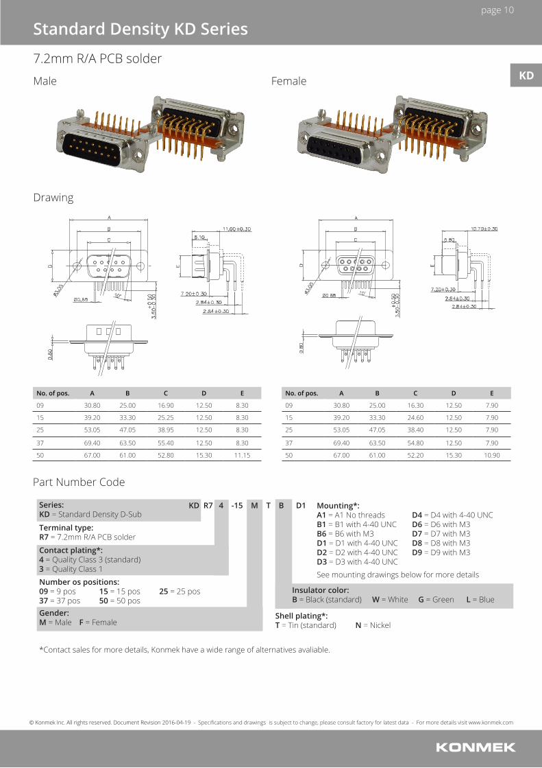
No. of pos. A B C D E
09 30.80 25.00 16.90 12.50 8.30
15 39.20 33.30 25.25 12.50 8.30
25 53.05 47.05 38.95 12.50 8.30
37 69.40 63.50 55.40 12.50 8.30
50 67.00 61.00 52.80 15.30 11.15
No. of pos. A B C D E
09 30.80 25.00 16.30 12.50 7.90
15 39.20 33.30 24.60 12.50 7.90
25 53.05 47.05 38.40 12.50 7.90
37 69.40 63.50 54.80 12.50 7.90
50 67.00 61.00 52.20 15.30 10.90
KD R7 4 -15 M T B D1Series:KD = Standard Density D-Sub
Mounting*:A1 = A1 No threadsB1 = B1 with 4-40 UNCB6 = B6 with M3D1 = D1 with 4-40 UNC D2 = D2 with 4-40 UNCD3 = D3 with 4-40 UNC
See mounting drawings below for more details
D4 = D4 with 4-40 UNC D6 = D6 with M3D7 = D7 with M3D8 = D8 with M3D9 = D9 with M3
Insulator color:B = Black (standard) W = White G = Green L = Blue
Gender:M = Male F = Female
*Contact sales for more details, Konmek have a wide range of alternatives avaliable.
Shell plating*:T = Tin (standard) N = Nickel
Terminal type:R7 = 7.2mm R/A PCB solder
Contact plating*:4 = Quality Class 3 (standard)3 = Quality Class 1
Number os positions:09 = 9 pos 15 = 15 pos 25 = 25 pos37 = 37 pos 50 = 50 pos
Standard Density KD Series
7.2mm R/A PCB solder
Male
Drawing
Female
Part Number Code
KD

page 11
© Konmek Inc. All rights reserved. Document Revision 2016-04-19 - Specifications and drawings is subject to change, please consult factory for latest data - For more details visit www.konmek.com
7.2mm R/A PCB solder
A1
D1/D6
D3/D8
B1/B6
D2/D7
D4/D9
Standard Density KD Series
Mounting KD

page 12
© Konmek Inc. All rights reserved. Document Revision 2016-04-19 - Specifications and drawings is subject to change, please consult factory for latest data - For more details visit www.konmek.com
9 pos
15 pos
25 pos
37 pos
50 pos
Standard Density KD Series
7.2mm R/A PCB solder PCB Layout for Male and Female connector KD

page 13
© Konmek Inc. All rights reserved. Document Revision 2016-04-19 - Specifications and drawings is subject to change, please consult factory for latest data - For more details visit www.konmek.com
No. of pos. A B C D E
09 30.80 25.00 16.90 12.50 8.30
15 39.20 33.30 25.25 12.50 8.30
25 53.05 47.05 38.95 12.50 8.30
37 69.40 63.50 55.40 12.50 8.30
50 67.00 61.00 52.80 15.30 11.15
No. of pos. A B C D E
09 30.80 25.00 16.30 12.50 7.90
15 39.20 33.30 24.60 12.50 7.90
25 53.05 47.05 38.40 12.50 7.90
37 69.40 63.50 54.80 12.50 7.90
50 67.00 61.00 52.20 15.30 10.90
KD R9 4 -15 M T B D1Series:KD = Standard Density D-Sub
Mounting*:A1 = A1 No threadsB1 = B1 with 4-40 UNCB6 = B6 with M3D1 = D1 with 4-40 UNC D2 = D2 with 4-40 UNCD3 = D3 with 4-40 UNC
See mounting drawings below for more details
D4 = D4 with 4-40 UNC D6 = D6 with M3D7 = D7 with M3D8 = D8 with M3D9 = D9 with M3
Insulator color:B = Black (standard) W = White G = Green L = Blue
Gender:M = Male F = Female
*Contact sales for more details, Konmek have a wide range of alternatives avaliable.
Shell plating*:T = Tin (standard) N = Nickel
Terminal type:R9 = 9.4mm R/A PCB solder
Contact plating*:4 = Quality Class 3 (standard)3 = Quality Class 1
Number of positions:09 = 9 pos 15 = 15 pos 25 = 25 pos37 = 37 pos 50 = 50 pos
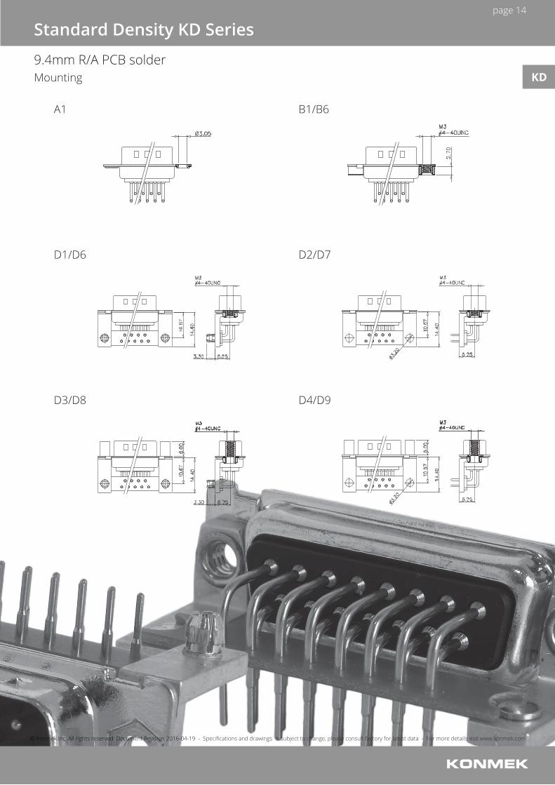
Standard Density KD Series
9.4mm R/A PCB solder
Male
Drawing
Female
Part Number Code
KD
page 14
© Konmek Inc. All rights reserved. Document Revision 2016-04-19 - Specifications and drawings is subject to change, please consult factory for latest data - For more details visit www.konmek.com
9.4mm R/A PCB solder
Standard Density KD Series
Mounting
A1
D1/D6
D3/D8
B1/B6
D2/D7
D4/D9
KD

page 15
© Konmek Inc. All rights reserved. Document Revision 2016-04-19 - Specifications and drawings is subject to change, please consult factory for latest data - For more details visit www.konmek.com
Standard Density KD Series
9.4mm R/A PCB solder
9 pos
15 pos
25 pos
37 pos
50 pos
PCB Layout for Male and Female connector KD

page 16
© Konmek Inc. All rights reserved. Document Revision 2016-04-19 - Specifications and drawings is subject to change, please consult factory for latest data - For more details visit www.konmek.com
Male
Drawing
Female
No. of pos. A B C D E
15 30.80 25.00 16.90 12.50 8.30
26 39.20 33.30 25.25 12.50 8.30
44 53.05 47.05 38.95 12.50 8.30
62 69.40 63.50 55.40 12.50 8.30
78 67.00 61.00 52.80 15.30 11.15
No. of pos. A B C D E
15 30.80 25.00 16.30 12.50 7.90
26 39.20 33.30 24.60 12.50 7.90
44 53.05 47.05 38.40 12.50 7.90
62 69.40 63.50 54.80 12.50 7.90
78 67.00 61.00 52.20 15.30 10.90
Part Number Code
KH S 4 -26 M T B H1Series:KH = High Density D-Sub
Mounting*:A1 = Mounting holeB1 = B1 with 4-40 UNCB6 = B6 with M3
Insulator color:B = Black (standard) W = White
Gender:M = Male F = Female
*Contact sales for more details, Konmek have a wide range of alternatives avaliable.
Shell plating*:T = Tin (standard) N = Nickel
Terminal type:S = Solder cup
Contact plating*:4 = Quality Class 3 (standard)3 = Quality Class 1
Number of positions:15 = 15 pos 26 = 26 pos 44 = 44 pos62 = 62 pos 78 = 78 pos
See mounting drawings below for more details
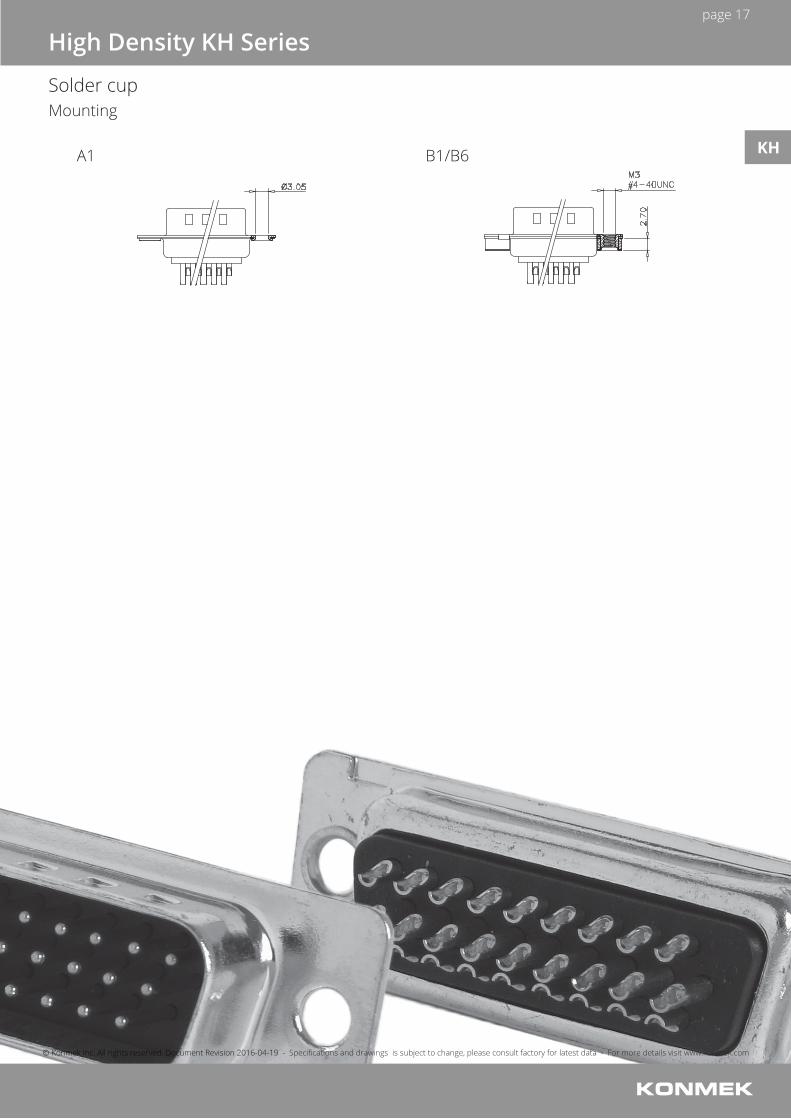
High Density KH Series
Solder cup
KH
page 17
© Konmek Inc. All rights reserved. Document Revision 2016-04-19 - Specifications and drawings is subject to change, please consult factory for latest data - For more details visit www.konmek.com
A1 B1/B6
High Density KH Series
Solder cup Mounting
KH

page 18
© Konmek Inc. All rights reserved. Document Revision 2016-04-19 - Specifications and drawings is subject to change, please consult factory for latest data - For more details visit www.konmek.com
No. of pos. A B C D E
15 30.80 25.00 16.90 12.50 8.30
26 39.20 33.30 25.25 12.50 8.30
44 53.05 47.05 38.95 12.50 8.30
62 69.40 63.50 55.40 12.50 8.30
78 67.00 61.00 52.80 15.30 11.15
No. of pos. A B C D E
15 30.80 25.00 16.30 12.50 7.90
26 39.20 33.30 24.60 12.50 7.90
44 53.05 47.05 38.40 12.50 7.90
62 69.40 63.50 54.80 12.50 7.90
78 67.00 61.00 52.20 15.30 10.90
KH T 4 -26 M T B C1Series:KH = High Density D-Sub
Mounting*:A1 = A1 No threadsB1 = B1 with 4-40 UNCB2 = B2 with 4-40 UNCB3 = B3 with 4-40 UNCB6 = B6 with M3 B7 = B7 with M3
See mounting drawings below for more details
B8 = B8 with M3C1 = C1 with 4-40 UNC C2 = C2 with 4-40 UNCC6 = C6 with M3C7 = C7 with M3
Insulator color:B = Black (standard) W = White
Gender:M = Male F = Female
*Contact sales for more details, Konmek have a wide range of alternatives avaliable.
Shell plating*:T = Tin (standard) N = Nickel
Terminal type:T = Straight PCB solder
Contact plating*:4 = Quality Class 3 (standard)3 = Quality Class 1
Number of positions:15 = 15 pos 26 = 26 pos 44 = 44 pos62 = 62 pos 78 = 78 pos
High Density KH Series
Straight PCB solder
Male
Drawing
Female
Part Number Code
KH

page 19
© Konmek Inc. All rights reserved. Document Revision 2016-04-19 - Specifications and drawings is subject to change, please consult factory for latest data - For more details visit www.konmek.com
A1
B2/B7
C1/C6
B1/B6
B3/B8
C2/C7
High Density KH Series
Straight PCB solder Mounting
KH

page 20
© Konmek Inc. All rights reserved. Document Revision 2016-04-19 - Specifications and drawings is subject to change, please consult factory for latest data - For more details visit www.konmek.com
15 pos
26 pos
44 pos
62 pos
78 pos
High Density KH Series
Straight PCB solder PCB Layout for Male connector
KH

page 21
© Konmek Inc. All rights reserved. Document Revision 2016-04-19 - Specifications and drawings is subject to change, please consult factory for latest data - For more details visit www.konmek.com
15 pos
26 pos
44 pos
62 pos
78 pos
High Density KH Series
Straight PCB solder PCB Layout for Female connector
KH

page 22
© Konmek Inc. All rights reserved. Document Revision 2016-04-19 - Specifications and drawings is subject to change, please consult factory for latest data - For more details visit www.konmek.com
No. of pos. A B C D E
15 30.80 25.00 16.90 12.50 8.30
26 39.20 33.30 25.25 12.50 8.30
44 53.05 47.05 38.95 12.50 8.30
62 69.40 63.50 55.40 12.50 8.30
78 67.00 61.00 52.80 15.30 11.15
No. of pos. A B C D E
15 30.80 25.00 16.30 12.50 7.90
26 39.20 33.30 24.60 12.50 7.90
44 53.05 47.05 38.40 12.50 7.90
62 69.40 63.50 54.80 12.50 7.90
78 67.00 61.00 52.20 15.30 10.90
KH R 4 -26 M T B D1Series:KH = High Density D-Sub
Mounting*:A1 = A1 No threadsB1 = B1 with 4-40 UNCB6 = B6 with M3D1 = D1 with 4-40 UNC D2 = D2 with 4-40 UNCD3 = D3 with 4-40 UNC
See mounting drawings below for more details
D4 = D4 with 4-40 UNC D6 = D6 with M3D7 = D7 with M3D8 = D8 with M3D9 = D9 with M3
Insulator color:B = Black (standard) W = White
Gender:M = Male F = Female
*Contact sales for more details, Konmek have a wide range of alternatives avaliable.
Shell plating*:T = Tin (standard) N = Nickel
Terminal type:R = R/A PCB solder
Contact plating*:4 = Quality Class 3 (standard)3 = Quality Class 1
Number of positions:15 = 15 pos 26 = 26 pos 44 = 44 pos62 = 62 pos 78 = 78 pos
High Density KH Series
R/A PCB solder
Male
Drawing
Female
Part Number Code
KH
page 23
© Konmek Inc. All rights reserved. Document Revision 2016-04-19 - Specifications and drawings is subject to change, please consult factory for latest data - For more details visit www.konmek.com
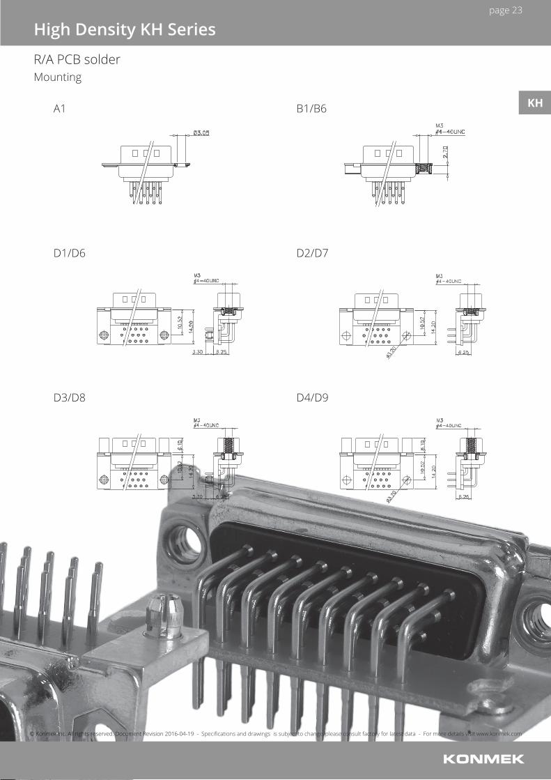
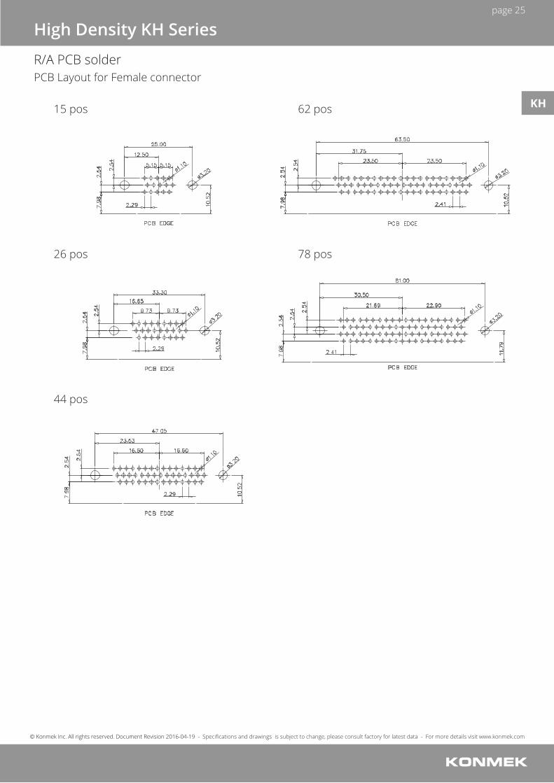
R/A PCB solder
A1
D1/D6
D3/D8
B1/B6
D2/D7
D4/D9
High Density KH Series
Mounting
KH

page 24
© Konmek Inc. All rights reserved. Document Revision 2016-04-19 - Specifications and drawings is subject to change, please consult factory for latest data - For more details visit www.konmek.com
15 pos
26 pos
44 pos
62 pos
78 pos
High Density KH Series
R/A PCB solder PCB Layout for Male connector
KH
page 25
© Konmek Inc. All rights reserved. Document Revision 2016-04-19 - Specifications and drawings is subject to change, please consult factory for latest data - For more details visit www.konmek.com
15 pos
26 pos
44 pos
62 pos
78 pos
High Density KH Series
R/A PCB solder PCB Layout for Female connector
KH