standalone cervical interbody fixation designed for ... - coroent small... · • the...
TRANSCRIPT
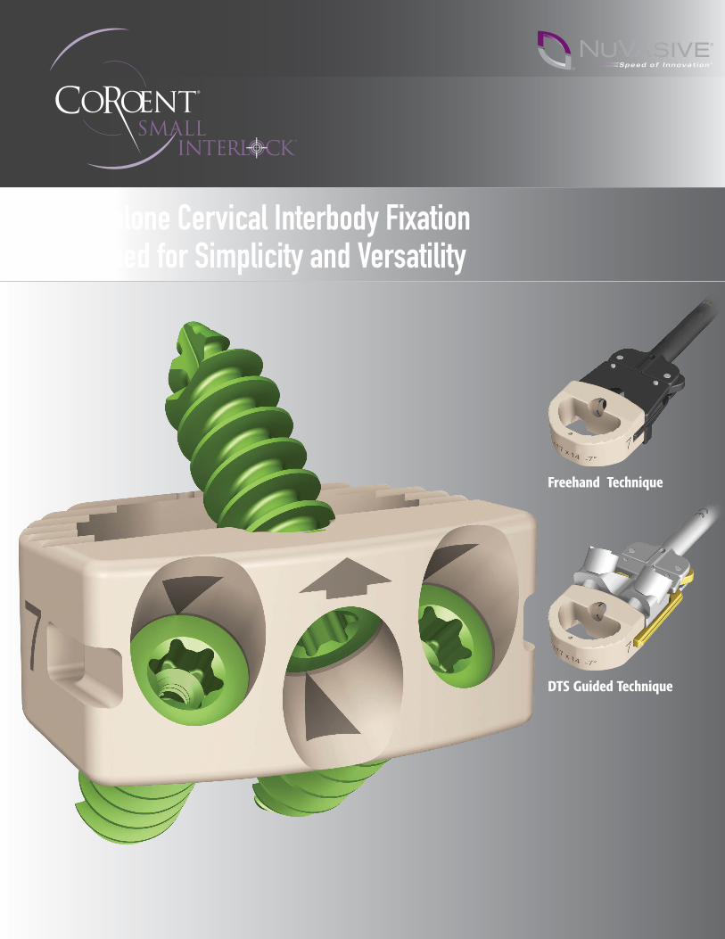
Standalone Cervical Interbody Fixation Designed for Simplicity and Versatility
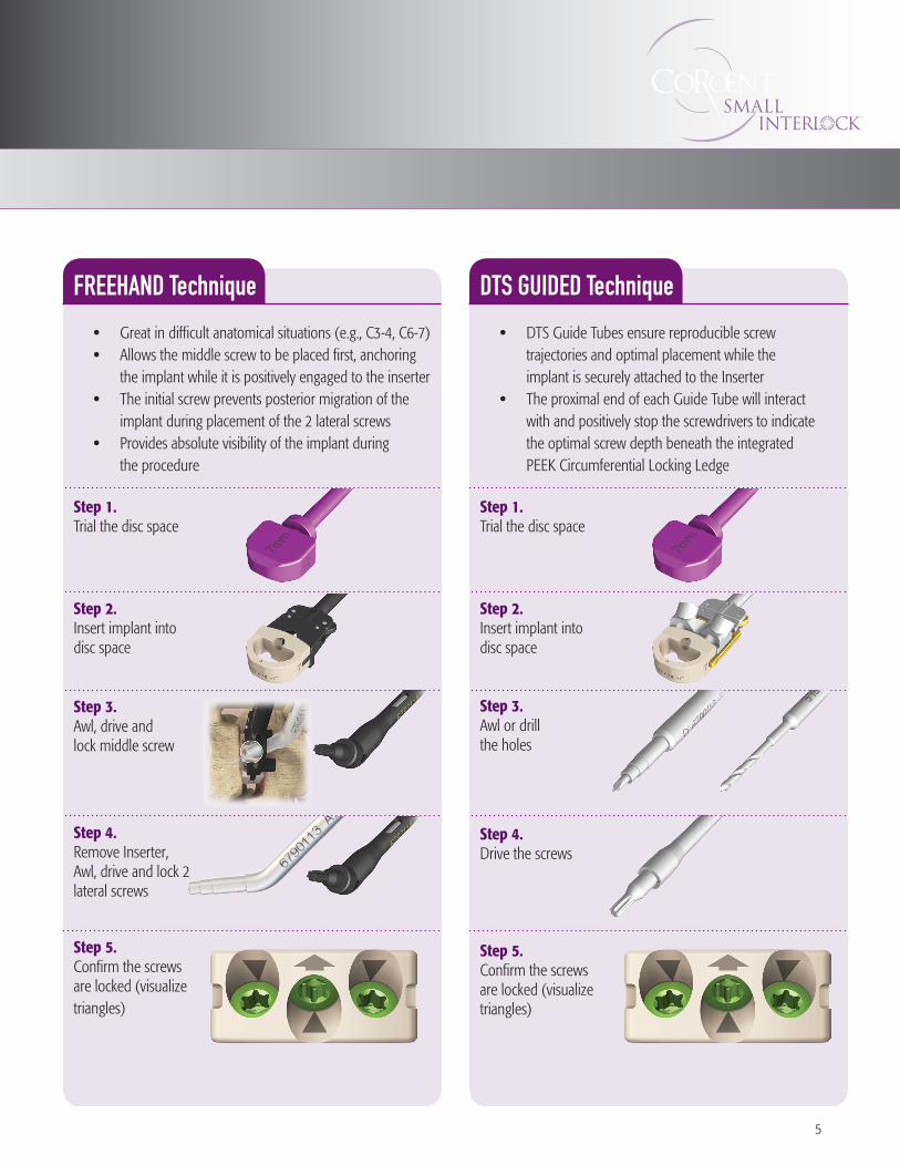
Freehand Technique
DTS Guided Technique
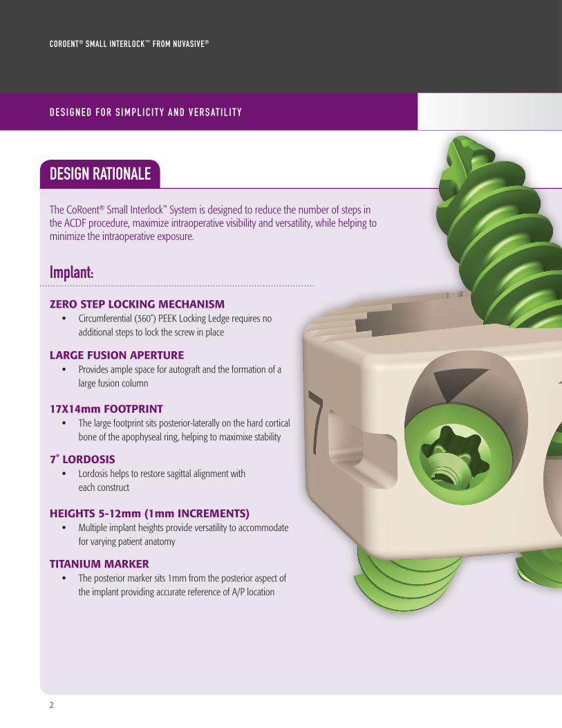
Implant:
Zero Step Locking MechaniSM • Circumferential (360˚) PEEK Locking Ledge requires no
additional steps to lock the screw in place
Large FuSion aperture • Provides ample space for autograft and the formation of a
large fusion column
17X14mm Footprint • The large footprint sits posterior-laterally on the hard cortical
bone of the apophyseal ring, helping to maximixe stability
7˚ LordoSiS • Lordosis helps to restore sagittal alignment with
each construct
heightS 5-12mm (1mm increMentS)• Multiple implant heights provide versatility to accommodate
for varying patient anatomy
titaniuM Marker • The posterior marker sits 1mm from the posterior aspect of
the implant providing accurate reference of A/P location
DESIGN RATIONALE The CoRoent® Small Interlock™ System is designed to reduce the number of steps in the ACDF procedure, maximize intraoperative visibility and versatility, while helping to minimize the intraoperative exposure.
CoRoent® Small InteRloCk™ FRom nUVaSIVe®
D e S I g n e D F o r S I m p l I C I t y a n D V e r S at I l I t y
2
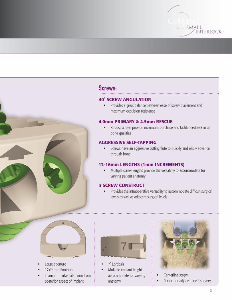
Screws:
40˚ Screw anguLation • Provides a great balance between ease of screw placement and
maximum expulsion resistance
4.0mm priMary & 4.5mm reScue • Robust screws provide maximum purchase and tactile feedback in all
bone qualities
aggreSSive SeLF-tapping • Screws have an aggressive cutting flute to quickly and easily advance
through bone
12-16mm LengthS (1mm increMentS) • Multiple screw lengths provide the versatiltiy to accommodate for
varying patient anatomy
3 Screw conStruct • Provides the intraoperative versatility to accommodate difficult surgical
levels as well as adjacent surgical levels
• Large aperture • 17x14mm Footprint • Titanium marker sits 1mm from
posterior aspect of implant
• 7˚ Lordosis • Multiple implant heights
accommodate for varying anatomy
• Centerline screw • Perfect for adjacent level surgery
3
4
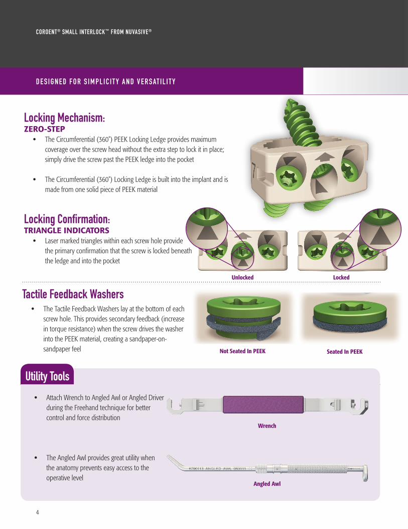
Locking Mechanism:Zero-Step • The Circumferential (360˚) PEEK Locking Ledge provides maximum
coverage over the screw head without the extra step to lock it in place; simply drive the screw past the PEEK ledge into the pocket
• The Circumferential (360˚) Locking Ledge is built into the implant and is made from one solid piece of PEEK material
Locking Confirmation:triangLe indicatorS • Laser marked triangles within each screw hole provide
the primary confirmation that the screw is locked beneath the ledge and into the pocket
Tactile Feedback Washers• The Tactile Feedback Washers lay at the bottom of each
screw hole. This provides secondary feedback (increase in torque resistance) when the screw drives the washer into the PEEK material, creating a sandpaper-on-sandpaper feel
Utility Tools
• Attach Wrench to Angled Awl or Angled Driver during the Freehand technique for better control and force distribution
• The Angled Awl provides great utility when the anatomy prevents easy access to the operative level
Not Seated In PEEK Seated In PEEK
Unlocked Locked
Wrench
Angled Awl
CoRoent® Small InteRloCk™ FRom nUVaSIVe®
D e S I g n e D F o r S I m p l I C I t y a n D V e r S at I l I t y
5
FREEHAND Technique
• Great in difficult anatomical situations (e.g., C3-4, C6-7) • Allows the middle screw to be placed first, anchoring
the implant while it is positively engaged to the inserter• The initial screw prevents posterior migration of the
implant during placement of the 2 lateral screws• Provides absolute visibility of the implant during
the procedure
Step 1. Trial the disc space
Step 2. Insert implant into disc space
Step 3. Awl, drive and lock middle screw
Step 4. Remove Inserter, Awl, drive and lock 2 lateral screws
Step 5. Confirm the screws are locked (visualize triangles)
DTS GUIDED Technique
• DTS Guide Tubes ensure reproducible screw trajectories and optimal placement while the implant is securely attached to the Inserter
• The proximal end of each Guide Tube will interact with and positively stop the screwdrivers to indicate the optimal screw depth beneath the integrated PEEK Circumferential Locking Ledge
Step 1. Trial the disc space
Step 2. Insert implant into disc space
Step 3. Awl or drill the holes
Step 4. Drive the screws Step 5. Confirm the screws are locked (visualize triangles)
6
CoRoent® Small InteRloCk™ FRom nUVaSIVe®
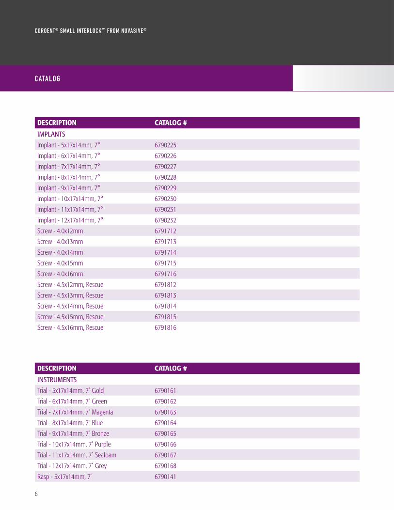
DESCRIPTION CATALOG #
IMPLANTS
Implant - 5x17x14mm, 7° 6790225
Implant - 6x17x14mm, 7° 6790226
Implant - 7x17x14mm, 7° 6790227
Implant - 8x17x14mm, 7° 6790228
Implant - 9x17x14mm, 7° 6790229
Implant - 10x17x14mm, 7° 6790230
Implant - 11x17x14mm, 7° 6790231
Implant - 12x17x14mm, 7° 6790232
Screw - 4.0x12mm 6791712
Screw - 4.0x13mm 6791713
Screw - 4.0x14mm 6791714
Screw - 4.0x15mm 6791715
Screw - 4.0x16mm 6791716
Screw - 4.5x12mm, Rescue 6791812
Screw - 4.5x13mm, Rescue 6791813
Screw - 4.5x14mm, Rescue 6791814
Screw - 4.5x15mm, Rescue 6791815
Screw - 4.5x16mm, Rescue 6791816
C ata l o g
DESCRIPTION CATALOG #
INSTRUMENTS
Trial - 5x17x14mm, 7˚ Gold 6790161
Trial - 6x17x14mm, 7˚ Green 6790162
Trial - 7x17x14mm, 7˚ Magenta 6790163
Trial - 8x17x14mm, 7˚ Blue 6790164
Trial - 9x17x14mm, 7˚ Bronze 6790165
Trial - 10x17x14mm, 7˚ Purple 6790166
Trial - 11x17x14mm, 7˚ Seafoam 6790167
Trial - 12x17x14mm, 7˚ Grey 6790168
Rasp - 5x17x14mm, 7˚ 6790141
7
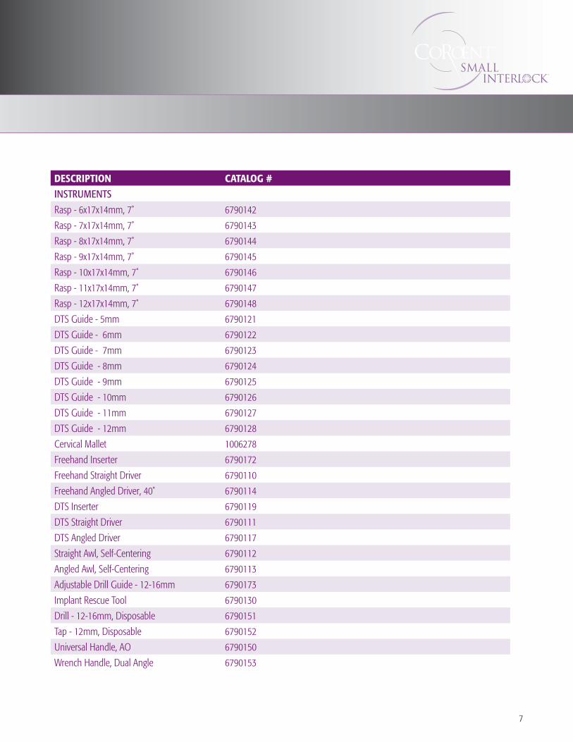
DESCRIPTION CATALOG #
INSTRUMENTS
Rasp - 6x17x14mm, 7˚ 6790142
Rasp - 7x17x14mm, 7˚ 6790143
Rasp - 8x17x14mm, 7˚ 6790144
Rasp - 9x17x14mm, 7˚ 6790145
Rasp - 10x17x14mm, 7˚ 6790146
Rasp - 11x17x14mm, 7˚ 6790147
Rasp - 12x17x14mm, 7˚ 6790148
DTS Guide - 5mm 6790121
DTS Guide - 6mm 6790122
DTS Guide - 7mm 6790123
DTS Guide - 8mm 6790124
DTS Guide - 9mm 6790125
DTS Guide - 10mm 6790126
DTS Guide - 11mm 6790127
DTS Guide - 12mm 6790128
Cervical Mallet 1006278
Freehand Inserter 6790172
Freehand Straight Driver 6790110
Freehand Angled Driver, 40˚ 6790114
DTS Inserter 6790119
DTS Straight Driver 6790111
DTS Angled Driver 6790117
Straight Awl, Self-Centering 6790112
Angled Awl, Self-Centering 6790113
Adjustable Drill Guide - 12-16mm 6790173
Implant Rescue Tool 6790130
Drill - 12-16mm, Disposable 6790151
Tap - 12mm, Disposable 6790152
Universal Handle, AO 6790150
Wrench Handle, Dual Angle 6790153

To order, please contact your NuVasive® Sales Consultant or Customer Service Representative today at:NuVasive, Inc. 7475 Lusk Blvd., San Diego, CA 92121 • phone: 800-475-9131 fax: 800-475-9134
NuVasive UK Limited 509 Centennial Park, Centennial Avenue, Elstree WD6 3FGphone: +44 (0) 208-238-7850 fax: +44 (0) 207-998-7818
www.nuvasive.com 9500723 A
©2011. NuVasive, Inc. All rights reserved. , NuVasive and CoRoent are federally registered trademarks of NuVasive, Inc.Speed of Innovation and Small Interlock are common law trademarks of NuVasive, Inc. Patent(s) pending.
0086
EC REP