stairmaster stepmill technical manual...stairmaster stepmill ® technical manual . last revised...
TRANSCRIPT

StairMaster StepMill® Technical Manual
Last revised 10/5/15

Important Safety Information The following pages are intended to educate service technicians on the basic maintenance and service actions for the StairMaster StepMills®. By following the enclosed instructions and maintenance schedule, you will extend the life of your equipment and help ensure it will withstand hours of use in your home/facility.
Before working on this equipment, pay attention to the following warnings:
• Read and understand the complete Owner's Manual. • Keep Owner's Manual for future reference. • Read and understand all warnings on this machine. If at any time the Warning stickers become loose, unreadable
or dislodged, contact Customer Service for replacement stickers. • Keep children away from this machine. Monitor them closely when near the machine. Parts that move and
appear dangerous to adults can appear safe to children. • Consult a physician before you start an exercise program. Stop exercising if you feel pain or tightness in your
chest, become short of breath, or feel faint. Contact your doctor before you use the machine again. Use the values calculated or measured by the machine's computer for reference purposes only.
• Before each use, examine this machine for loose parts or signs of wear. Do not use if found in this condition. Pay special attention to the steps. Contact Customer Service for repair information.
• Maximum user weight limit: 350lbs. (159kgs). Do not use if you are over this weight. • Do not wear loose clothing or jewelry. This machine contains moving parts. • Set up and operate this machine on a solid, level, horizontal surface. • Do not step off the machine until the Steps have fully stopped. • Do not operate this machine outdoors or in moist or wet locations. • Keep at least 19.7"(0.5m) on each side of the machine clear. This is the recommended safe distance for access
and passage around and emergency dismounts from the machine. Keep third parties out of this space when machine is in use.
• Do not over exert yourself during exercise. Operate the machine in the manner described in this manual. • When the machine is put in a studio or club environment, it can only be used in areas where access and control
of the machine is managed by approved staff. The degree of management depends on the user's ability to recognize and prevent danger to third parties during the exercise movement.
To decrease risk of burns, fire, electric shock, or injury to persons:
• An appliance must not be left unattended when plugged in. Unplug from outlet when not in operation and before you put on or remove parts.
• Close supervision is necessary when this appliance is used by or near children or disabled persons. • Use this appliance only for its intended use as described in this manual. Do not use attachments that are not
recommended by the manufacturer. • Do not operate this appliance if it has a damaged cord or plug, if it is not working correctly, if it has been dropped
or damaged, or fallen into water. Return the appliance to a service center for examination and repair. • Keep the cord away from heated surfaces. • Do not drop or put any object into any opening. • Do not use outdoors. • To disconnect, turn all controls to the off position, then remove plug from outlet.
Last revised 10/5/15

Index StairMaster Gauntlet and SM5 - Commercial StepMill Product Details
Recommended Tools
Preventative Maintenance
Major Components
Mechanical Adjustments
o Alternator Brush Replacement o Alternator Removal / Replacement o Transmission Removal / Replacement o Step Chain Removal / Replacement o Upper / Lower Sprocket Removal / Replacement
Consoles
Electrical Troubleshooting
o Power Trace o No Resistance o Choppy Resistance o Relay Board Tests o Other Key Points o Contact Heart Rate Test
SM3 – Light Commercial / Residential StepMill Product Detail
Last revised 10/5/15

Gauntlet
Technical Specs Product Dimensions 58" L x 34" W x 89" H (147cm L x 86cm W x 226cm H) Product Weight 328 lbs (149 kg) Max User Weight 350 lbs (159 kg) Power Requirements Input Voltage 100-240 VAC 50/60 Hz 100 VA Display Three choices of displays. 1) 10” Touch Screen Console with integrated TV Tuner (TSE-1) and
2) 10” Touch Screen Console (TS-1) and 3) Backlit LCD Console (D-1). TV Option 15.6" digital television with HD capabilities (SMV-1) Workouts Landmark Challenge Program where users climb well known landmarks from around the world.
Standard programs that members are familiar with are also included. *Landmark Challenge feature available on the TSE-1/TS-1 Console Only
Warm Bar Functions Contact Heart Rate sensors and automatic stop button Fitness Tests Multi-stage Fit Test, CPAT Fire Fit Test and WFI StepMill® Test Drive System Electronically controlled alternator with chain drive precisely controls the stair speed Step Action Revolving staircase with eight steps, 8" (20cm) high, 9” (23cm) deep and 22" (56cm) wide Step Rate
24 to 162 steps/minute
Heart Rate Monitoring
Polar® compatible wireless; contact sensors
US Commercial Warranty Frame 15 Years Parts 3 Years Labor 1 Year Note: Warranty terms are for U.S. only and vary by region. Contact the distributor in your country and region.
Last revised 10/5/15

SM5
Technical Specs Product Dimensions 58" L x 34" W x 89" H (147cm L x 86cm W x 226cm H) Product Weight 343 lbs (156 kg) Max User Weight 350 lbs (159 kg) Power Requirements Input Voltage 100-240 VAC 50/60 Hz 100 VA Display Three choices of displays. 1) 10” Touch Screen Console with integrated TV Tuner (TSE-1) and
2) 10” Touch Screen Console (TS-1) and 3) Backlit LCD Console (D-1). Workouts 15.6" digital television with HD capabilities (SMV-1) Fitness Tests Landmark Challenge Program where users climb well known landmarks from around the world.
Standard programs that members are familiar with are also included. *Landmark Challenge feature available on the TSE-1/TS-1 Console Only
Drive System Electronically controlled alternator with chain drive precisely controls the stair speed Step Action Revolving staircase with eight steps, 8" (20cm) high, 9” (23cm) deep and 22" (56cm) wide US Commercial Warranty Frame 15 Years Mechanical Parts 3 Years Wear items/Electronics 1 Year Note: Warranty terms are for U.S. only and vary by region. Contact the distributor in your country and region.
Last revised 10/5/15

Tools
# Units Tool Suggested Manufacturer Minimum Specifications 1 Multi-meter Various Digital, Continuity, 1 Socket Set, SAE Various 1/4" - 5/8" 1 Socket Set, Metric Various 4mm - 21mm 1 Socket driver Various 1 Open end wrenches, SAE Various 1/4" - 3/4" 1 Open end wrenches, Metric Various 4mm - 17mm 1 Hex Bit Socket Set, SAE Various 5/64 - 3/8 1 Hex Bit Socket Set, Metric Various 4mm - 14mm 1 Adjustable Wrench Various 1 Torque Wrench Various 1 Torque Wrench Various
1+ Screwdriver Set, Phillips Various 1+ Screwdriver Set, Flat Various 1 Tape Measure Various 1 Ball Pene Hammer Various 10 oz
1+ Rubber Mallet Various 1 USB - Flash Drive Various 1 GB 4 Motorcycle straps, adjustable Various 1 Loctite 680 Various 1 1’ Jumper wire w/ alligator clips Various
50 zip ties Various 4' 50 zip ties Various 8'
Last revised 10/5/15

Preventative Maintenance Cleaning
1. Do not use glass cleaners or any other household cleaners on the console. Clean the console daily with a water dampened cloth and wipe dry after cleaning.
2. Clean the exterior of the machine daily using soap and water or a diluted, non-mineral based household cleaner such as Fantastik, or Simple Green.
Note: The safety and performance of this product can be maintained only if it is inspected regularly for damage and wear. Pay particular attention to the components most susceptible to wear such as steps and lower side covers. Remove any damaged machine from service and replace damaged components immediately.
Inspection
1. Inspect the frame for any rust, bubbling, or paint chips during the daily cleaning. The salt in perspiration can damage the unpainted surfaces. Repair the damaged area with a touch-up paint kit from customer service.
Maintenance Schedule
General Maintenance Daily Weekly Monthly Comments
Check Safety & Warning Labels
X
Spot Check Step Chains X Alternator Belt Tension X Tension to 40-54 lbs*inch Lubrication Drive Chains X
(or every 300 hours)
30W Motor Oil
Bearing Plate X Multi-Purpose Grease/White Lithium Cleaning Clean Console X Clean with a water dampened cloth & wipe
dry after cleaning Clean Side Covers X Clean exterior with soap & water, or diluted
household cleaner
Parts and Service
Regular and scheduled maintenance will prolong the life of your equipment. Only use genuine StairMaster replacement parts. External Power Supply
The external power supply is supplied with the unit and plugs into a standard 115 volt, 15 amp outlet, or a 220-240 volt 50Hz, 10 amp outlet. All major voltage plugs are available. The power inlet is located on the underside of the machine.
Last revised 10/5/15

Major Components Step Hardware
Composite plastic step with a rubber tread built into step top. The step top and kick plate are held together and to the step chains by step hinges, threaded step shafts, nylon spacers, bearings, washers, and bolts.
Drive System The upper and lower sprockets are held to the chassis of the machine by pillow block bearings and connect the left-side and right-side step chains. Pillow blocks can be adjusted on the frame to ensure alignment from upper to lower sprockets and for tensioning the step chains. As the steps rotate, bearings in the step shaft hardware ride down the rails on bearing plates. These bearing plates need to be greased with white lithium, or marine grease.
Last revised 10/5/15

Major Components Drive System Side view of StepMill with covers removed shows the upper sprocket connection to the transmission via drive chain. The transmission is in place to ensure gearing up/down is handled appropriately during a user workout.
The upper sprocket has an inner sprocket that connects the drive chain to the transmission sprocket. There is an idler arm and sprocket on the transmission to assist with keeping tension on the drive chain. Ensure the idler arm moves with the chain and that the bolt that connects it to the transmission is not over tensioned.
Resistance System Resistance is applied to the steps of the machine by use of an alternator. 12VDC power from the lower board is fed into the alternator to control the amount of resistance it applies. The resistance system (alternator) connects the gearing system, or transmission of the machine via poly-V belt.
Last revised 10/5/15

Major Components Resistance System The alternator and transmission connect to the chassis of StepMill as shown. The alternator’s connection pivots allowing the poly-V belt to be tensioned. Tension to 40-54 lbs*inch, or 1/4 of a turn (90 degrees) of deflection. Ensure the belt is not too tight, or damage to the alternator bearings or transmission housing can occur. The inner pulley of the transmission has a set screw so the poly-V belt can be aligned with the alternator pulley.
Wiring connections to Alternator: W5: White-B+ Alt. output voltage W3: Brown Field, Alternator Control Current W6: Black Ground, Alternator return W4: Blue Tach, velocity signal to console
Alternator Brush Assembly
Alternator
Last revised 10/5/15
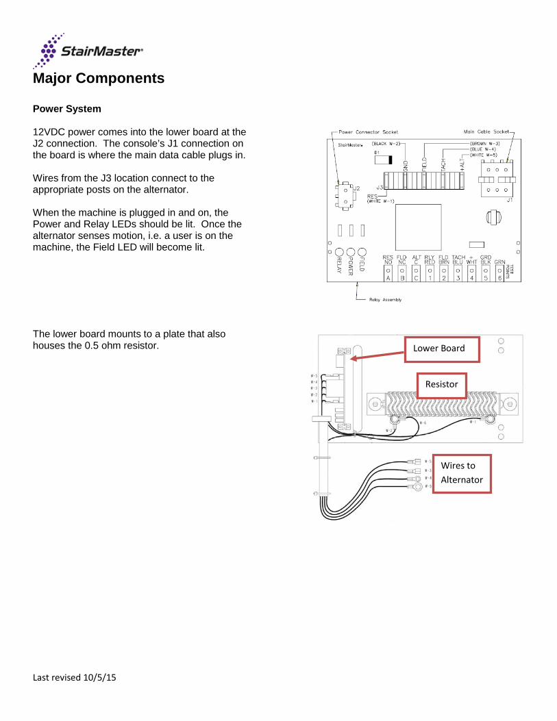
Major Components Power System 12VDC power comes into the lower board at the J2 connection. The console’s J1 connection on the board is where the main data cable plugs in. Wires from the J3 location connect to the appropriate posts on the alternator. When the machine is plugged in and on, the Power and Relay LEDs should be lit. Once the alternator senses motion, i.e. a user is on the machine, the Field LED will become lit.
The lower board mounts to a plate that also houses the 0.5 ohm resistor.
Lower Board
Resistor
Wires to Alternator
Last revised 10/5/15

Major Components Power System
Last revised 10/5/15

Mechanical Adjustments
1. Remove alternator belt and inspect for cracks, fraying or any other unusual or excessive wear.
2. Spin alternator pulley to check bearings.
3. Inspect alternator pulley for wear.
4. Check that the transmission pulley set screw is tightened on the flat side of the shaft (check alternator/transmission pulley alignment).
5. Remove the drive chain and inspect it for frozen links.
6. Spin transmission drive sprocket input one complete revolution. The transmission pulley output should turn 19 times.
7. Check that the transmission drive sprocket set screw is tight.
8. Visually inspect both upper and lower sprocket assemblies including pillow block bearings for signs of unusual or excessive wear.
9. Check side to side alignment of sprocket assemblies by measuring from the outside face of each sprocket to the outside edge of the corresponding bearing rail. Measurement on sprockets should be 1 11/16" left justified.
10. Inspect step shafts and bearings in each step assembly for wear and lubricate step shafts and bearings rails as necessary (Refer to the recommended general maintenance schedule or owner’s manual).
11. Inspect hinged portion of all step assemblies for wear and lubricate with 30 WT motor oil or light bearing grease.
Last revised 10/5/15

Mechanical Adjustments Alternator Brush Replacement
1. Remove user-right side cover 2. Remove brown wire from W3 (FLD BRN) post of alternator. 3. Loosen ¼” bolts on W3 post, or alternator brush assembly 4. Verify brush length and quality. We recommend replacing brushes that are ¼” or less.
Alternator Replacement
1. Remove side covers. 2. (Optional) Remove a step shaft, allowing top-down access for transmission removal. 3. Remove poly-V belt from inner transmission and alternator pulleys. 4. Remove the transmission bracket, between transmission and alternator, from the alternator body. 5. Remove W3 (brown), W4 (blue), W5 (white), and W6 (black) wires from posts of the alternator. 6. Remove the Nyloc nut, screw, spacer and hardware that mount the alternator onto the chassis of the machine. 7. Mount the new alternator onto the pivot assembly. 8. Reconnect the transmission bracket to the alternator body. 9. Reconnect W3 (brown), W4 (blue), W5 (white), and W6 (black) wires to the corresponding posts of the alternator. 10. Reconnect the poly-V belt between the transmission and alternator and ensure proper alignment and tension. 11. Once proper belt tension is set tighten the alternator adjustment bolt on the transmission bracket of the alternator,
and pivot assembly hardware. 12. Replace side covers.
Transmission Replacement
1. Remove side covers. 2. Remove drive chain master link and chain from transmission / upper sprocket. 3. (Optional) Remove a step shaft, allowing top-down access for transmission removal. 4. Remove poly-V belt from inner transmission and alternator pulleys 5. Remove the transmission brace from the transmission body, leaving the other end connected to the machine
chassis. 6. Remove the transmission bracket, between transmission and alternator, from the transmission body. 7. Loosen the 4 bolts that mount the transmission to the chassis of the machine. Take note of the rubber pad that
sits between the transmission and machine. 8. Remove transmission and remove the sprocket, idler arm assembly, and inner pulley and key for use on the new
transmission. 9. Assemble transmission parts from Step 7 onto new/replacement transmission. 10. Bolt new transmission onto the chassis of the machine, ensuring to replace the rubber pad. 11. Reconnect the transmission bracket from the alternator and the brace from the chassis. 12. Align the inner transmission pulley, so it is in alignment with the alternator pulley, and tighten the set screw. 13. Reconnect the poly-V belt between the transmission and alternator and ensure proper alignment and tension. 14. Reconnect drive chain and master link. 15. Replace side covers.
Last revised 10/5/15

Mechanical Adjustments Step Chain replacement
1. Remove side covers. 2. Remove drive chain master link and chain from transmission / upper sprocket. 3. Loosen 9/16” nuts on all 4 pillow blocks from chassis. 4. Count threads on pillow block adjustment screws, and loosen on all pillow block bearings/step chains. 5. On one side of the machine, remove step chain master link and break chain. 6. Connect new chain to old chain with master link. 7. Remove step shaft bolt and hardware on one side of the machine. 8. Remove step shafts from the old chain and reconnect to the new chain, reassembling the spacers, bearings,
washer and nut one shaft at a time per side. 9. Once the 8 step shafts have been installed into the new chain, reconnect the new step chain with the master link. 10. Once one new side’s step chain is on, repeat steps for other side. 11. Replace drive chain and master link 12. Use pillow block adjustment screws to ensure upper and lower sprockets are in alignment and tension on the new
step chains is appropriate. Tighten 9/16” bolts to chassis. 13. Tighten 9/16” bolts on the pillow blocks to chassis. 14. Replace side covers.
Upper/Lower Sprocket Replacement
1. Prepare a clean work area 2. Remove side covers 3. Remove console 4. Tip machine forward, so the console mast is resting on the ground. 5. Remove drive chain master link and chain from transmission / upper sprocket. 6. With an assistant, loosen and remove 9/16” nuts on upper sprocket pillow blocks until the pillow block bearing is
removed from the chassis and the upper sprocket is no longer connected. 7. Remove upper sprocket from machine. 8. Remove pillow block bearings from the upper sprocket and fit to the new sprocket using the set screws on the
outer collar. If pillow block bearings are bad, replace. 9. Lower the new upper sprocket into the teeth of the left and right side step chains. Ensure the inner sprocket is on
the proper side and corresponds with the transmission sprocket. Verify alignment and placement within the teeth of the chains.
10. Replace pillow block bearings to chassis of machine and snug up the 9/16” bolts, but do not fully tighten. 11. Rotate steps to ensure there is no binding and stairs rotate smoothly. 12. Use pillow block adjustment screws to ensure upper and lower sprockets are in alignment and tension on the new
step chains is appropriate. 13. Tighten 9/16” bolts on the pillow blocks to chassis. 14. Replace side covers. 15. For lower sprocket replacement, omit step 4.
Last revised 10/5/15

Consoles
7000 PT / 4400 / 4600
C5 Console • Red LED Readout • Non-replacable overlay • Repair/Exchange
through National Gym Supply
C40 Console – Blue Faced Overlay
• Blue LCD Readout • Console PN#: 055-
0034 • Replacable overlay:
PN# - SM27780-001, SM27790, SM27779
• Display Board PN#: SM40070-001
• Process Board PN#: SM27130
• Menu map available
C40 Console – Gray Faced Overlay
• Blue LCD Readout • Console PN#: 055-
0034 • Replacable overlay
PN#: SM25673, SM27790, SM27779
• Display Board PN#: SM40070-001
• Process Board PN#: SM27130
• Menu map available
Last revised 10/5/15

SM916 / SC916
C51/C52 LCD Console • Blue LCD Readout • Console PN#: 003-
3625 • Replacable overlay
PN#: SM40468 • Menu map available
SM5 / SC5
D1 LCD Console • Blue LCD Readout • Console PN#: 050-
0035 • Replacable overlay
PN#: 050-0287 • USB port for software
upload • Menu map available
TS-1 / TSE-1 Console • Touchscreen (TS-1)
PN#: 050-0129 • TV Optional (TSE-1)
PN#: 050-0034 • USB port for software
upload • Ipod connector for use
with iDevice • Menu map available
Last revised 10/5/15

Gauntlet / Freeclimber
D1 LCD Console (Black) • Blue LCD Readout • Console PN#: 050-
0035-35 • Replacable overlay
PN#: 050-0287 • USB port for software
upload • Menu map available
TS-1 / TSE-1 Console (Black) • Touchscreen (TS-1)
PN#: 050-0129-35 • TV Optional (TSE-1)
PN#: 050-0034-35 • USB port for software
upload • Menu map available
Last revised 10/5/15

Electrical Troubleshooting Power Trace
1. No Resistance When Stepping
Remove the right side panel to view the three LED’s on the lower PCB board. Begin moving the staircase. If all three of the red LEDs on the relay board are illuminated but there is no resistance, inspect the alternator brushes (SM24557) if worn or the alternator (SM22900).
050-0154
050-0161
050-0201
050-0105
050-0039
050-0038
050-0236 (ASSY)
SM23545
050-0232
Last revised 10/5/15

2. No Resistance and No Field Light
• Begin moving the staircase. • Staircase freewheels and field LED does
not light. • Perform tach test by entering
diagnostics. • If there is no tach signal sensed on
console. o Check for .6 to .7 volts AC at the
W-4 (Tach) terminal of the alternator.
o If no voltage, remove the blue tach wire from the alternator, while staircase is moving. Touch the tach wire to
the field terminal. If the field LED lights,
replace the alternator. o If the voltage checks good,
remove the blue connector from the W-4 (Tach) terminal of the alternator. Lightly scrape the connector and re-install. Re-check.
• If still bad, replace the console.
3. Staircase has resistance but is choppy during exercise.
• Inspect Main Cable for Corrosion at all connections.
• Check Load Resistor for a reading of .5 to.6 Ohms. If lower than .5 ohms, then replace the load resistor (SM24989).
• If load resistor checks good, replace the alternator brushes (SM24557) or alternator (SM22900).
Last revised 10/5/15

4. Relay board tests.
• Disconnect the main cable from relay board J1 terminal.
• With power on, place jumper across GND/BLK and RLY/RED test points.
o Relay LED should light. If not, replace lower PCB board (SM23545).
• With power on, place jumper across +/WHT and FLD/BRN test points.
o Field LED should light. If not, replace lower PCB board (SM23545).
● Disconnect the black W-2 ground wire. With power on now, place a jumper on the +/WHT test point and with the other end touch the ALT/C test point, then jump the +/WHT to the FLD/NC test point, and then jump the =/WHT to the RES/NO test point. Once the test is completed, re-attach the black W-2 ground wire and the J-1 main cable socket which was removed at the beginning of the relay board test .
o Field LED should light. If not, replace lower PCB board (SM23545).
Last revised 10/5/15

5. Other Key Points
• Remember that the only signal that will prevent the field LED from lighting on the relay board is the tach signal from the blue wire. The console must receive an rpm signal to activate the field current to the alternator that is PWM controlled.
• If you suspect the alternator, disconnect all the wires and check the resistance across the field terminal and the alternator housing; a typical Alternator should read around 4 Ohms or higher.
• The Field LED on the relay board will flicker at higher speed levels. This is the PWM signal from the console to the field terminal of the alternator to control resistance / speed. If you experience full resistance through all levels and the field light doesn’t flicker; replace the console.
● To verify that the load resistor is working correctly, you must ohm the resistor out using your multi meter. The load resistor must read above .5 ohms. If the resistor reads anything less than .5 ohms, then replace the load resistor (SM24989).
• Always perform mechanical troubleshooting in addition to electrical trouble shooting for resistance problems.
Last revised 10/5/15

Last revised 10/5/15

Last revised 10/5/15

Last revised 10/5/15

Alternator / Resistance Testing The colored connections to the alternator are as follows: White-B+ Alternator output voltage Brown Field, Alternator Control Current Black Ground, Alternator return Blue Tachometer, velocity signal back to console Resistance over gravity is performed by the alternator in the StepMill. When the console senses a user with staircase movement, the console should be enabling full field current to the alternator. Field current is provided from the external power supply, through the console, into the lower board and wired into the alternator’s field terminal. Under this condition, the console should also be driving the lower board's J1 pin 1 low, switching the .5ohm load resistor onto the alternator’s B+. The alternator’s B+ should rise as a result of field current, but its voltage will depend on the weight of the user and resulting velocity. Resistance is achieved by the oppositions of internal magnetic fields when field current is applied. The user’s weight will affect the alternator’s RPM under this condition, and under full field current conditions the voltage is not controlled. But, with the large gear ratio and full field current applied, the resistance should be at maximum, and the step rate should be at a minimum. Once a user starts a workout, the console controls the alternator’s field current attempting to maintain the desired step rate. This signal is Pulse Width Modulated (PWM) from 0V to 12V, the level of the loaded external supply. If the step rate is fast, the console will deliver field current longer, if the step rate is slow, it will deliver less field current. The only situation where no field current would be present during a workout is if a very light weight person was attempting to achieve a step rate that could not be achieved by their weight overcoming the frictional resistance of the system. In this case, the console would keep field current off, or no induced resistance. During workouts the alternator’s B+ increases as a function of speed and user weight. For high level workouts with heavy weight users, B+ levels of 20V could be witnessed. Power entry is at the bottom of the unit. The 12V 2.5A supply enters via the main power harness, and enters into the PCB via J2. LED2 indicates power is present, but 12V should still be confirmed with a volt meter. Power and control interface to the console is provided at location J1. 12V is provided up to the console at J1 pin 4, and GND pin 5. In addition to alternator field current, the console controls the loading of the alternator’s B+ with the .5ohm resistor which is switched by the lower board's relay. When the console detects a user has stepped on the staircase, it immediately applies full field current, and turns on the power relay to load B+ with .5ohm. LED1 is an indicator the console is attempting to close the relay, but this should be confirmed with a VOM. If no resistance is felt, confirm 10V to 12V is being applied to the alternator’s field. This should always be present once a user is detected, and before a workout has begun. Confirm the additional load is being switched also, which is controlled by a low voltage on J1 pin 1. The operation of the power relay can be confirmed by unplugging the unit, and removing the console connection at J1. Install external power again, and an ohmmeter should show continuity from B+ to field on the 23545's terminal strip. Last revised 10/5/15
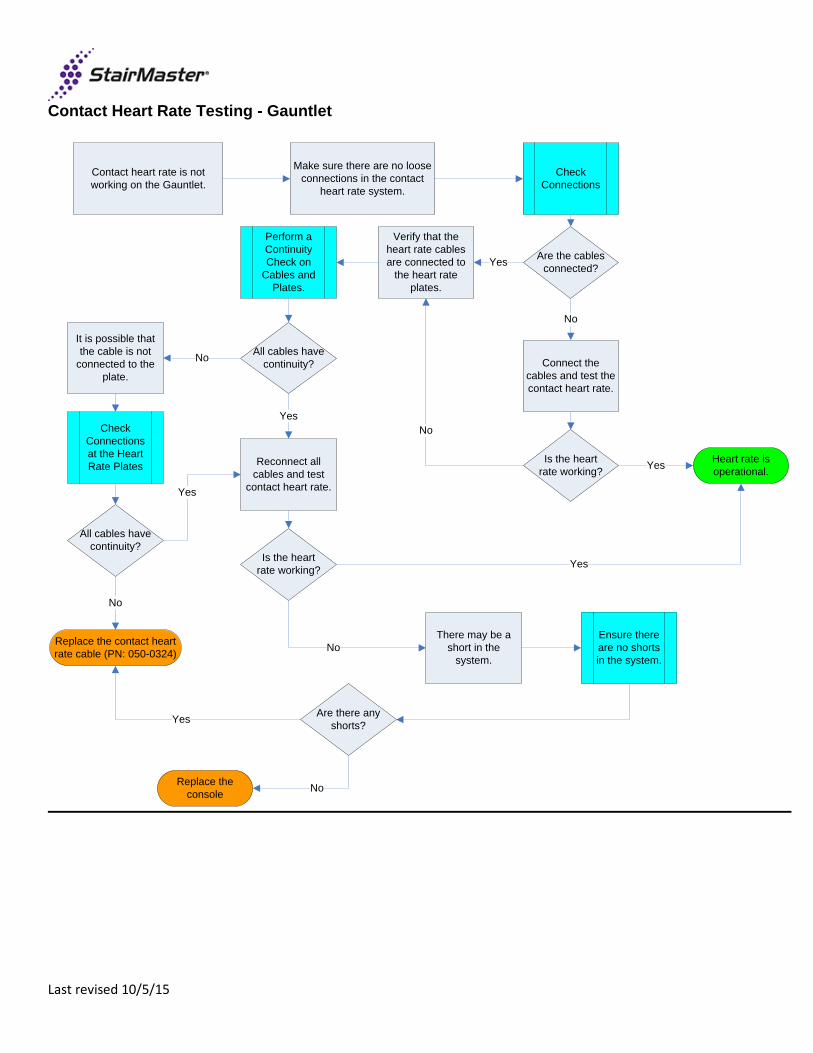
Contact Heart Rate Testing - Gauntlet
Contact heart rate is not working on the Gauntlet.
Make sure there are no loose connections in the contact
heart rate system.
Check Connections
Are the cables connected?Yes
No
Connect the cables and test the contact heart rate.
Is the heart rate working?
Heart rate is operational.Yes
Verify that the heart rate cables are connected to
the heart rate plates.
Perform a Continuity Check on
Cables and Plates.
No
All cables have continuity?
Reconnect all cables and test
contact heart rate.
Is the heart rate working?
It is possible that the cable is not
connected to the plate.
Check Connections at the Heart Rate Plates
No
All cables have continuity?
Yes
Yes
Replace the contact heart rate cable (PN: 050-0324)
No
Yes
There may be a short in the
system.
Ensure there are no shorts in the system.
No
Are there any shorts?
Replace the console No
Yes
Last revised 10/5/15

SM3 – Light Commercial / Residential
Technical Specs Product Dimensions 46" L x 29" W x 73" H (117cm x 74cm x 185cm) Product Weight 227 lbs (103 kg) Power Requirements Input Voltage 100-240 VAC 5060 Hz 100 VA Display Backlit LCD Console Workouts Standard console programs Drive System Electronically controlled brake generator and drive chain precisely controls the
stair speed allowing users to exercise smoothly within their comfort zones Step Action Revolving staircase with six, 6” inch steps Step Surface 9"x17" U.S. Commercial Warranty User Environment Residential Light Commercial Frame Lifetime 10 Years Mechanical 5 Years 2 Years Electronics 2 Years 1 Year Wear Items 1 Year 1 Year Labor 1 Year 1 Year
Last revised 10/5/15
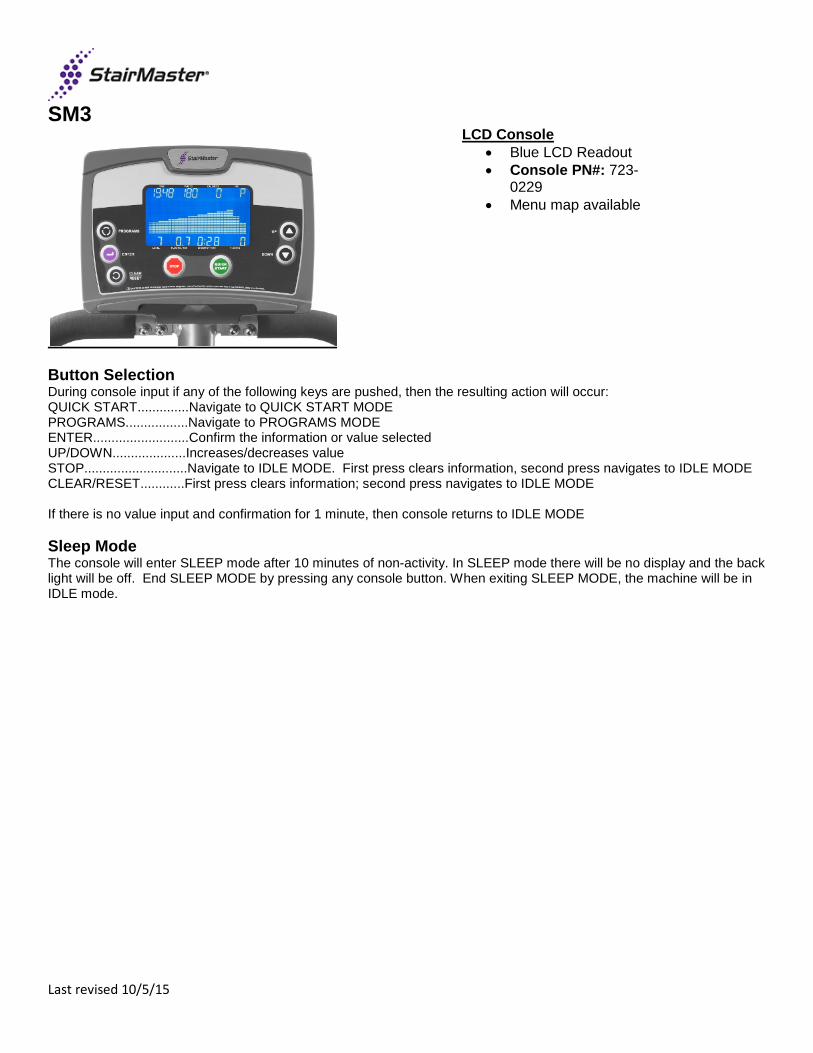
SM3
LCD Console • Blue LCD Readout • Console PN#: 723-
0229 • Menu map available
Button Selection During console input if any of the following keys are pushed, then the resulting action will occur: QUICK START..............Navigate to QUICK START MODE PROGRAMS.................Navigate to PROGRAMS MODE ENTER..........................Confirm the information or value selected UP/DOWN....................Increases/decreases value STOP............................Navigate to IDLE MODE. First press clears information, second press navigates to IDLE MODE CLEAR/RESET............First press clears information; second press navigates to IDLE MODE If there is no value input and confirmation for 1 minute, then console returns to IDLE MODE Sleep Mode The console will enter SLEEP mode after 10 minutes of non-activity. In SLEEP mode there will be no display and the back light will be off. End SLEEP MODE by pressing any console button. When exiting SLEEP MODE, the machine will be in IDLE mode.
Last revised 10/5/15

CORPORATE HEADQUARTERS
Core Health & Fitness
4400 NE 77th Avenue, Suite 300
Vancouver, WA 98662
(888) 678-2476
For further support on StairMaster products, please visit:
http://support.stairmaster.com
Last revised 10/5/15