stainless w-interlock joint aw型継手(ステンレス製) … · 20 aw stainless w-interlock...
TRANSCRIPT

20
AW
STAINLESS W-INTERLOCK JOINT AW型継手(ステンレス製)STAINLESS W-INTERLOCK JOINT AW
■ 構造断面図 Internal Structure
■ 材質 Material
この管継手を構成する、継手本体、ナット及びフェルールの材質は全て、SUS316を使用しております。
The material of all of the main body, nut, and ferrule is SUS316.
■ 適用するパイプの種類 Applicable Pipe
JIS G 3459配管用ステンレス鋼鋼管に規定するSUS304TP、 SUS316TPに準ずるステンレス鋼鋼管。 The stainless steel pipe corresponding to SUS316TP or SUS304TP specified
as the stainless steel pipe for plumbing of JIS G 3459.
■ 適用するパイプの基本条件 Basic conditions of the Applicable Pipe
■ 特長 Features
● 高圧・高温・超低温に耐えられます。 Having resistance to high temperature, high pressure, and ultra low
temperature.● 締付けトルクが小さく、捻れが生じない理想的なシールです。 Tightening torque is small, and no torsion is caused.
● 衝撃・振動にビクともしません。 Remains unmoved in a shock or vibration.
● ナットのねじ部に焼き付きを起こしません。 No seizing is caused in the screw part of a nut.
● 真空ラインに使用できます。 Can be used in the vacuum line.
● 繰り返し脱着に優れています。 Superior in desorption repeatedly.
■ 管継手の仕様及管厚圧力 Specifications/Pipe Thickness and Working Pressure
● 使用温度:-196℃~600℃ Operating temperature range:-196℃~600℃
● 使用圧力:下表参照 Working pressure:Please refer to the table below
(MPa)
パイプ外径(mm)
Pipe outside diameter
パイプ厚さ(mm) Pipe thickness
0.5 1 1.5 2
3 49.4 102.9
4 36.1 77.1
6 49.5 77.1
8 36.1 56.4
10 28.1 44.0
12 23.2 36.1 49.5
計算条件Calculating conditions
※管材の最小引張値52.5Kgf/mm2 安全率4 Minimum tensile strength value of pipe:52.5kgf/mm2 Safety rate:4
※管厚さの許容値をZeroとした場合 Tolerance of tube thickness:0
※温度-29℃~37.8℃ Temperature:-29℃~37.8℃
パイプの外径寸法(O.D.)Outside diameter 3、4、6、8、10、12mm
外径許容差O.D. Tolerance ±0.05mm
パイプの表面硬度Surface hardness
HRB90以下(HV190以下)HRB90 or less(HV190 or less)
パイプの表面状態Surface condition
肌あれ、キズなどの有害な欠陥が無きこと。There must not be harmful defects, such as roughness or wound.
■ 注意事項 Note1. パイプの切断は、パイプカッターにて直角に切断し、切断外周にバリがないよう充分に削り取ってください。 また、パイプ端から30mm以内にキズ、異物等がないように目視にて確認をしてください。 Please cut the pipe perpendicularly with the pipe cutter, and fully remove the flash from cutting perimeter. Moreover, please confirm visually that there are no wound or foreign substance etc. within 30mm from the pipe ends.
2. ナットを締付ける際のスパナは、ナット六角径に合ったものを使用してください。 When tightening the nut, please use the spanner suitable for the diameter of the nut hexagon.
3. 継手の取付角度を変える場合は、必ず継手のナットを緩めてから方向を変えてください。 When changing the attachment angle of the fitting, please be sure to change the direction after loosening the nut of the fitting.
4. 高所及び配管スペースの狭い場所等で締付け困難な場合は、仮締付け作業を行い、締付け不足にならないように注意してください。 If the tightening work is difficult in the high or narrow plumbing space, do temporary tightening work, and be sure not to become the shortage of tightening.
ステンレス製締付継手.indd 20 14/01/27 9:27
21
AW型継手(ステンレス製)■締付け方法 Method of Tightening
■取外し後の再締付け方法 Method of Re-tightening
■配管上の注意 The Cautions on Plumbing
■その他 Other
① ナットを外さないで、そのままパイプを継手の中に差し込み、パイプ先端を継手内部の肩にあたるまで 差し込んでください。(注:パイプは直角に切断し、端面の内外のバリはていねいに取り除いてあるか確認してください。)
Please insert the pipe, without removing a nut, into the fitting until the pipe tip hits the shoulder of the fitting inside.(Note:Please cut the pipe perpendicularly, and be sure that flash is fully removed from cutting perimeter.)
② ナットを手締めにて、回らなくなる迄締め込んでください。この位置を〇ポイントとし、 目印をつけてください。
Please tighten the nut by hand until it stops. Please consider this position as 〇 point and mark it.
③ 継手本体をスパナ等でしっかりと動かないように固定し、 もう一本のスパナでナットを右記の回転数にて締め込んでください。 (注:本体を回転させての締め込みはしないでください。)
Please fix the main body of the fitting with a spanner well not to move. Then tighten the nut by another spanner at degrees written on the right. (Note:Please do not turn the main body when tightening.)
注意:プラスチックチューブを接続する際には、インサートリングを必ず 併用して、φ4~φ12のチューブ締付け回転数は11/4~11/2回転で締付けてください。Note:When connecting the plastic tube, please be sure to use the insert ring together. For connecting φ4~12 plastic tube, please tighten 11/4~11/2 turns(450~540 degrees).
① ナットを緩める前にナットの位置を確認してからナットを外してください。(基準の締付回転位置)
Please loosen and remove a nut after checking the position of a nut.(The standard position of tightening.)
② フロントフェルールが正しい位置に装置されているか再確認してください。 Please reconfirm that the front ferrule is equipped to the correct position.
③ 再取付け前に継手本体のテーパ面及びフロント、リア部に異物が付着していないことを確認してください。 Before reconnecting, please confirm that the foreign substances are not adhering to the taper side, the front, or the rear part of the body.
④ フロントフェルールが完全に継手本体のテーパーシート面に密着するまで差し込んでからナットを 手締めにて締付けてください。(管端で本体テーパー部にスリ傷などつかないようにご注意の上、差し込んでください。)
Please tighten the nut by hand after inserting until the front ferrule sticks to the taper sheet side of the body completely.(When inserting, please be careful not to damage the taper part of the main body with the edge of pipe.)
⑤ 次にスパナにて、ナットを緩める前の位置より わずかに多く締付けてください。(右記)
Then, please slightly tighten the nut with a spanner from the standard position of tightening.(Please see the right diagram.)
注意:プラスチックチューブ使用時の再締付けにつきましては、1/8~1/4回転で締付けてください。Note: When reconnecting the plastic tube, Please tighten1/8~1/4turn(45~90 degrees).
ナットを緩める前の位置The standard position of tightening
再締付け完了位置(わずかに多く締込む)Re-tightening completion position (Tightened slightly more.)
W-INTERLOCK JOINTはパイプ端を継手本体の管突き当て部に突き当てた状態で締付ける事が基本であり、その為には最小限の直管部が必要です。Tightening the pipe in the condition that the pipe end bumps the "tube stop part" of the main body of the fitting is the foundation of W-INTERLOCK JOIT. Therefore the minimum straight pipe length (L) is required.
W-INTERLOCK JOINTは厳重な品質管理のもとで製作致しておりますが、万一、漏洩等発生した場合増し締めにて確認を行うとともに、詳しい使用状況、締付け状態等確認しながら原因究明致しますので、先ずは弊社迄ご相談ください。We are producing W-INTERLOCK JOINT under the severe quality control, but, if leakage etc. are generated by any chance, first of all, please consult us.We will confirm it by tightening, and will investigate a cause with confirming the detailed situation of use, or the tightening state,etc.
パイプ外径(mm)Pipe outside diameter
L(直管部最小寸法)(mm)L(Minimum straight length of pipe)
R(最小寸法)(mm)R(Minimum bending radius)
3 19 7
4 20 9
6 21 13.5
8 22 18
10 24 25
12 31 36
ステンレス製締付継手.indd 21 14/01/27 9:27
22
AW型継手(ステンレス製)
AW
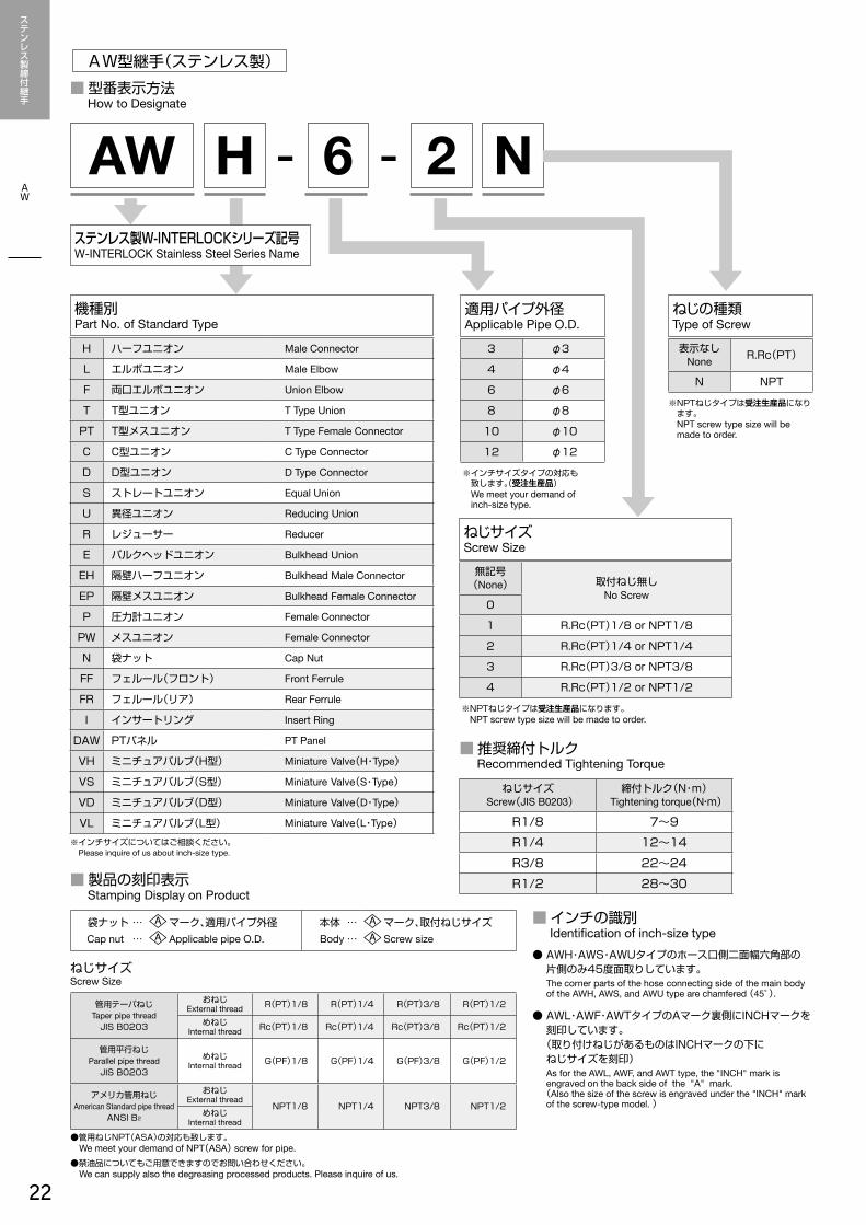
■ 推奨締付トルク Recommended Tightening Torque
■ 製品の刻印表示 Stamping Display on Product
ねじサイズScrew Size
ねじサイズScrew(JIS B0203)
締付トルク(N・m)Tightening torque(N・m)
R1/8 7~9
R1/4 12~14
R3/8 22~24
R1/2 28~30
■ 型番表示方法 How to Designate
AW H - 6 - 2 N
ねじの種類Type of Screw
機種別Part No. of Standard Type
適用パイプ外径Applicable Pipe O.D.
ねじサイズScrew Size
H ハーフユニオン Male Connector
L エルボユニオン Male Elbow
F 両口エルボユニオン Union Elbow
T T型ユニオン T Type Union
PT T型メスユニオン T Type Female Connector
C C型ユニオン C Type Connector
D D型ユニオン D Type Connector
S ストレートユニオン Equal Union
U 異径ユニオン Reducing Union
R レジューサー Reducer
E バルクヘッドユニオン Bulkhead Union
EH 隔壁ハーフユニオン Bulkhead Male Connector
EP 隔壁メスユニオン Bulkhead Female Connector
P 圧力計ユニオン Female Connector
PW メスユニオン Female Connector
N 袋ナット Cap Nut
FF フェルール(フロント) Front Ferrule
FR フェルール(リア) Rear Ferrule
I インサートリング Insert Ring
DAW PTパネル PT Panel
VH ミニチュアバルブ(H型) Miniature Valve(H・Type)
VS ミニチュアバルブ(S型) Miniature Valve(S・Type)
VD ミニチュアバルブ(D型) Miniature Valve(D・Type)
VL ミニチュアバルブ(L型) Miniature Valve(L・Type)
3 φ3
4 φ4
6 φ6
8 φ8
10 φ10
12 φ12
※ インチサイズタイプの対応も 致します。(受注生産品)
We meet your demand of inch-size type.
無記号(None) 取付ねじ無し
No Screw0
1 R.Rc(PT)1/8 or NPT1/8
2 R.Rc(PT)1/4 or NPT1/4
3 R.Rc(PT)3/8 or NPT3/8
4 R.Rc(PT)1/2 or NPT1/2
※ NPTねじタイプは受注生産品になります。 NPT screw type size will be made to order.
表示なしNone R.Rc(PT)
N NPT
※ NPTねじタイプは受注生産品になります。
NPT screw type size will be made to order.
袋ナット …Cap nut …
マーク、適用パイプ外径Applicable pipe O.D.
本体 …Body …
マーク、取付ねじサイズScrew size
管用テーパねじTaper pipe thread
JIS B0203
おねじExternal thread R(PT)1/8 R(PT)1/4 R(PT)3/8 R(PT)1/2
めねじInternal thread Rc(PT)1/8 Rc(PT)1/4 Rc(PT)3/8 Rc(PT)1/2
管用平行ねじParallel pipe thread
JIS B0203
めねじInternal thread G(PF)1/8 G(PF)1/4 G(PF)3/8 G(PF)1/2
アメリカ管用ねじAmerican Standard pipe thread
ANSI B2
おねじExternal thread
NPT1/8 NPT1/4 NPT3/8 NPT1/2めねじ
Internal thread
●管用ねじNPT(ASA)の対応も致します。 We meet your demand of NPT(ASA) screw for pipe.●禁油品についてもご用意できますのでお問い合わせください。 We can supply also the degreasing processed products. Please inquire of us.
※インチサイズについてはご相談ください。 Please inquire of us about inch-size type.
ステンレス製W-INTERLOCKシリーズ記号W-INTERLOCK Stainless Steel Series Name
■ インチの識別 Identification of inch-size type● AWH・AWS・AWUタイプのホース口側二面幅六角部の
片側のみ45度面取りしています。 The corner parts of the hose connecting side of the main body
of the AWH, AWS, and AWU type are chamfered (45°).
● AWL・AWF・AWTタイプのAマーク裏側にINCHマークを刻印しています。
(取り付けねじがあるものはINCHマークの下に ねじサイズを刻印)
As for the AWL, AWF, and AWT type, the "INCH" mark is engraved on the back side of the "A" mark.
(Also the size of the screw is engraved under the "INCH" mark of the screw-type model. )
ステンレス製締付継手.indd 22 14/01/27 9:27
23
AW型継手(ステンレス製)ハーフユニオンAWH・エルボユニオンAWL
ハーフユニオンMale ConnectorAWH
エルボユニオンMale ElbowAWL
(unit:mm)
型番Model No.
適用パイプ外径φApplicable pipe O.D.
T
P(R or NPT) A B C D E F
(HEX)G
(HEX) H質量(g)Mass
AWH-3-1 3 1/8 32.9 11 15.9 13.4 2.5 12 12 26 23
AWH-3-2 3 1/4 34.9 13 15.9 13.4 2.5 14 12 28 32
AWH-4-1 4 1/8 35.8 11 17.8 15.3 3.5 14 14 28.5 31
AWH-4-2 4 1/4 37.8 13 17.8 15.3 3.5 14 14 30.5 38
AWH-6-1 6 1/8 35.9 11 17.9 15.4 5 14 14 28.5 28
AWH-6-2 6 1/4 37.9 13 17.9 15.4 5 14 14 30.5 35
AWH-6-3 6 3/8 38.9 14 17.9 15.4 5 17 14 31.5 49
AWH-6-4 6 1/2 44.4 19 17.9 15.4 5 22 14 37 84
AWH-8-1 8 1/8 36.8 11 18.8 16.8 5 14 15.87 29 31
AWH-8-2 8 1/4 38.8 13 18.8 16.8 6 14 15.87 31 44
AWH-8-3 8 3/8 39.8 14 18.8 16.8 6 17 15.87 32 82
AWH-8-4 8 1/2 45.3 19 18.8 16.8 6 22 15.87 37.5 85
AWH-10-2 10 1/4 39.8 13 19.8 17.8 7 17 19 32 49
AWH-10-3 10 3/8 40.8 14 19.8 17.8 8 17 19 33 56
AWH-10-4 10 1/2 46.3 19 19.8 17.8 8 22 19 38.5 83
AWH-12-2 12 1/4 42.8 13 22.8 22.8 7 22 23 32 79
AWH-12-3 12 3/8 43.8 14 22.8 22.8 9 22 23 33 83
AWH-12-4 12 1/2 49.3 19 22.8 22.8 10 22 23 38.5 102
※NPTねじタイプは受注生産品になります。 NPT screw type size will be made to order.
(unit:mm)
型番Model No.
適用パイプ外径φApplicable pipe O.D.
T
P(R or NPT) A B C D E G
(HEX) H質量(g)Mass
AWL-3-1 3 1/8 24.9 11 22 13.4 2.5 12 18 32
AWL-4-1 4 1/8 27.8 11 22 15.3 3.5 14 20.5 45
AWL-4-2 4 1/4 27.8 13 24 15.3 3.5 14 20.5 52
AWL-6-1 6 1/8 27.9 11 22 15.4 5 14 20.5 50
AWL-6-2 6 1/4 27.9 13 24 15.4 5 14 20.5 44
AWL-6-3 6 3/8 28.9 14 27 15.4 5 14 21.5 78
AWL-6-4 6 1/2 30.9 17 35 15.4 5 14 23.5 149
AWL-8-1 8 1/8 28.8 11 22 16.8 5 15.87 21 47
AWL-8-2 8 1/4 28.8 13 24 16.8 6 15.87 21 52
AWL-8-3 8 3/8 29.8 14 27 16.8 6 15.87 22 79
AWL-8-4 8 1/2 31.8 17 35 16.8 6 15.87 24 149
AWL-10-2 10 1/4 30.8 13 27 17.8 7 19 23 76
AWL-10-3 10 3/8 30.8 14 27 17.8 8 19 23 81
AWL-10-4 10 1/2 32.8 17 35 17.8 8 19 25 151
AWL-12-2 12 1/4 35.8 13 28 22.8 7 23 25 132
AWL-12-3 12 3/8 35.8 15 30 22.8 9 23 25 86
AWL-12-4 12 1/2 35.8 17 35 22.8 10 23 25 159
※NPTねじタイプは受注生産品になります。 NPT screw type size will be made to order.
ステンレス製締付継手.indd 23 14/01/27 9:27
24
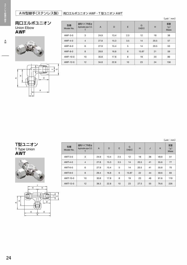
AW型継手(ステンレス製) 両口エルボユニオンAWF・T型ユニオンAWT
AW
両口エルボユニオンUnion ElbowAWF
T型ユニオンT Type UnionAWT
(unit:mm)
型番Model No.
適用パイプ外径φApplicable pipe O.D.
TA D E G
(HEX) H質量(g)Mass
AWF-3-0 3 24.9 13.4 2.5 12 18 38
AWF-4-0 4 27.8 15.3 3.5 14 20.5 57
AWF-6-0 6 27.9 15.4 5 14 20.5 53
AWF-8-0 8 28.8 16.8 6 15.87 21 59
AWF-10-0 10 30.8 17.8 8 19 23 89
AWF-12-0 12 34.8 22.8 10 23 24 156
(unit:mm)
型番Model No.
適用パイプ外径φApplicable pipe O.D.
TA D E G
(HEX) H J K質量(g)Mass
AWT-3-0 3 24.9 13.4 2.5 12 18 36 49.8 51
AWT-4-0 4 27.8 15.3 3.5 14 20.5 41 55.6 77
AWT-6-0 6 27.9 15.4 5 14 20.5 41 55.8 70
AWT-8-0 8 29.4 16.8 6 15.87 22 44 59.6 83
AWT-10-0 10 30.8 17.8 8 19 23 46 61.6 119
AWT-12-0 12 38.3 22.8 10 23 27.5 55 76.6 226
ステンレス製締付継手.indd 24 14/01/27 9:27
25
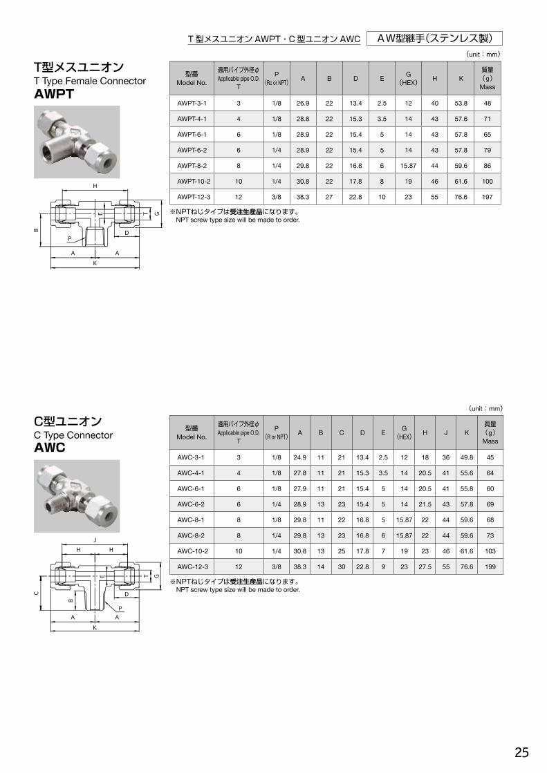
AW型継手(ステンレス製)T型メスユニオンAWPT・C型ユニオンAWC
T型メスユニオンT Type Female Connector AWPT
(unit:mm)
型番Model No.
適用パイプ外径φApplicable pipe O.D.
T
P(Rc or NPT) A B D E G
(HEX) H K質量(g)Mass
AWPT-3-1 3 1/8 26.9 22 13.4 2.5 12 40 53.8 48
AWPT-4-1 4 1/8 28.8 22 15.3 3.5 14 43 57.6 71
AWPT-6-1 6 1/8 28.9 22 15.4 5 14 43 57.8 65
AWPT-6-2 6 1/4 28.9 22 15.4 5 14 43 57.8 79
AWPT-8-2 8 1/4 29.8 22 16.8 6 15.87 44 59.6 86
AWPT-10-2 10 1/4 30.8 22 17.8 8 19 46 61.6 100
AWPT-12-3 12 3/8 38.3 27 22.8 10 23 55 76.6 197
※NPTねじタイプは受注生産品になります。 NPT screw type size will be made to order.
C型ユニオンC Type ConnectorAWC
(unit:mm)
型番Model No.
適用パイプ外径φApplicable pipe O.D.
T
P(R or NPT) A B C D E G
(HEX) H J K質量(g)Mass
AWC-3-1 3 1/8 24.9 11 21 13.4 2.5 12 18 36 49.8 45
AWC-4-1 4 1/8 27.8 11 21 15.3 3.5 14 20.5 41 55.6 64
AWC-6-1 6 1/8 27.9 11 21 15.4 5 14 20.5 41 55.8 60
AWC-6-2 6 1/4 28.9 13 23 15.4 5 14 21.5 43 57.8 69
AWC-8-1 8 1/8 29.8 11 22 16.8 5 15.87 22 44 59.6 68
AWC-8-2 8 1/4 29.8 13 23 16.8 6 15.87 22 44 59.6 73
AWC-10-2 10 1/4 30.8 13 25 17.8 7 19 23 46 61.6 103
AWC-12-3 12 3/8 38.3 14 30 22.8 9 23 27.5 55 76.6 199
※NPTねじタイプは受注生産品になります。 NPT screw type size will be made to order.
ステンレス製締付継手.indd 25 14/01/27 9:27
25
AW型継手(ステンレス製)T型メスユニオンAWPT・C型ユニオンAWC
T型メスユニオンT Type Female Connector AWPT
(unit:mm)
型番Model No.
適用パイプ外径φApplicable pipe O.D.
T
P(Rc or NPT) A B D E G
(HEX) H K質量(g)Mass
AWPT-3-1 3 1/8 26.9 22 13.4 2.5 12 40 53.8 48
AWPT-4-1 4 1/8 28.8 22 15.3 3.5 14 43 57.6 71
AWPT-6-1 6 1/8 28.9 22 15.4 5 14 43 57.8 65
AWPT-6-2 6 1/4 28.9 22 15.4 5 14 43 57.8 79
AWPT-8-2 8 1/4 29.8 22 16.8 6 15.87 44 59.6 86
AWPT-10-2 10 1/4 30.8 22 17.8 8 19 46 61.6 100
AWPT-12-3 12 3/8 38.3 27 22.8 10 23 55 76.6 197
※NPTねじタイプは受注生産品になります。 NPT screw type size will be made to order.
C型ユニオンC Type ConnectorAWC
(unit:mm)
型番Model No.
適用パイプ外径φApplicable pipe O.D.
T
P(R or NPT) A B C D E G
(HEX) H J K質量(g)Mass
AWC-3-1 3 1/8 24.9 11 21 13.4 2.5 12 18 36 49.8 45
AWC-4-1 4 1/8 27.8 11 21 15.3 3.5 14 20.5 41 55.6 64
AWC-6-1 6 1/8 27.9 11 21 15.4 5 14 20.5 41 55.8 60
AWC-6-2 6 1/4 28.9 13 23 15.4 5 14 21.5 43 57.8 69
AWC-8-1 8 1/8 29.8 11 22 16.8 5 15.87 22 44 59.6 68
AWC-8-2 8 1/4 29.8 13 23 16.8 6 15.87 22 44 59.6 73
AWC-10-2 10 1/4 30.8 13 25 17.8 7 19 23 46 61.6 103
AWC-12-3 12 3/8 38.3 14 30 22.8 9 23 27.5 55 76.6 199
※NPTねじタイプは受注生産品になります。 NPT screw type size will be made to order.
ステンレス製締付継手.indd 25 14/01/27 9:27

26
AW型継手(ステンレス製)
AW
D型ユニオンAWD・ストレートユニオンAWS
D型ユニオンD Type Connector AWD
(unit:mm)
型番Model No.
適用パイプ外径φApplicable pipe O.D.
T
P(R or NPT) A B D E G
(HEX) H J K質量(g)Mass
AWD-3-1 3 1/8 24.9 11 13.4 2.5 12 18 39 45.9 45
AWD-4-1 4 1/8 27.8 11 15.3 3.5 14 20.5 41.5 48.8 65
AWD-6-1 6 1/8 27.9 11 15.4 5 14 20.5 41.5 48.9 43
AWD-6-2 6 1/4 28.9 13 15.4 5 14 21.5 44.5 51.9 69
AWD-8-1 8 1/8 29.8 11 16.8 6 15.87 22 44 51.8 68
AWD-8-2 8 1/4 29.8 13 16.8 6 15.87 22 45 52.8 73
AWD-10-2 10 1/4 30.8 13 17.8 8 19 23 48 55.8 102
AWD-12-3 12 3/8 38.3 14 22.8 10 23 27.5 57.5 67.8 199
※NPTねじタイプは受注生産品になります。 NPT screw type size will be made to order.
ストレートユニオンEqual UnionAWS
(unit:mm)
型番Model No.
適用パイプ外径φApplicable pipe O.D.
TA C D E F
(HEX)G
(HEX) H質量(g)Mass
AWS-3-0 3 37.8 15.9 13.4 2.5 12 12 24 27
AWS-4-0 4 42.6 17.8 15.3 3.5 14 14 28 31
AWS-6-0 6 42.8 17.9 15.4 5 14 14 28 38
AWS-8-0 8 44.6 18.8 16.8 6 14 15.87 29 49
AWS-10-0 10 46.6 19.8 17.8 8 17 19 31 68
AWS-12-0 12 52.6 22.8 22.8 10 22 23 31 111
ステンレス製締付継手.indd 26 14/01/27 9:27
27
AW型継手(ステンレス製)異径ユニオンAWU・レジューサーAWR
異径ユニオンReducing UnionAWU
レジューサーReducerAWR
(unit:mm)
型番Model No.
適用パイプ外径φApplicable pipe O.D. A C1 C2 D1 D2 E F
(HEX)G1
(HEX)G2
(HEX) H質量(g)MassT1 T2
AWU-3.4-0 3 4 40.7 15.9 17.8 13.4 15.3 2.5 14 12 14 26.5 36
AWU-4.6-0 4 6 42.7 17.8 17.9 15.3 15.4 3.5 14 14 14 28 39
AWU-6.8-0 6 8 43.7 17.9 18.8 15.4 16.8 5 14 14 15.87 28.5 41
AWU-8.10-0 8 10 45.6 18.8 19.8 16.8 17.8 6 17 15.87 19 30 59
AWU-10.12-0 10 12 49.6 19.8 22.8 17.8 22.8 8 22 19 23 31 95
(unit:mm)
型番Model No.
適用パイプ外径φApplicable pipe O.D. A C D E F
(HEX)G
(HEX) H質量(g)MassT1 T2
AWR-3.4-0 3 4 40.9 15.9 13.4 2.5 12 12 34 18
AWR-3.6-0 3 6 40.9 15.9 13.4 2.5 12 12 34 19
AWR-4.6-0 4 6 43.8 17.8 15.3 3.5 14 14 36.5 27
AWR-4.8-0 4 8 43.8 17.8 15.3 3.5 14 14 36.5 28
AWR-6.8-0 6 8 43.9 17.9 15.4 5 14 14 36.5 26
AWR-6.10-0 6 10 48.9 17.9 15.4 5 14 14 41.5 28
AWR-8.10-0 8 10 49.8 18.8 16.8 6 14 15.87 42 31
AWR-8.12-0 8 12 53.8 18.8 16.8 6 14 15.87 46 33
AWR-10.12-0 10 12 54.8 19.8 17.8 8 17 19 47 46
ステンレス製締付継手.indd 27 14/01/27 9:27

28
AW型継手(ステンレス製)
AW
バルクヘッドユニオンAWE・隔壁ハーフユニオンAWEH・隔壁メスユニオンAWEP
バルクヘッドユニオンBulkhead UnionAWE
隔壁ハーフユニオンBulkhead Male ConnectorAWEH
(unit:mm)
型番Model No.
適用パイプ外径φApplicable pipe O.D.
TA B C D E F
(HEX)G
(HEX) H取付穴径Panel Hole
Size
最大取付板厚Max.Panel Thickness
質量(g)Mass
AWE-3-0 3 49.8 22 15.9 13.4 2.5 14 12 36 8.5 10 37
AWE-4-0 4 59.6 28 17.8 15.3 3.5 17 14 45 11.5 13 59
AWE-6-0 6 59.8 28 17.9 15.4 5 17 14 45 11.5 13 53
AWE-8-0 8 62.6 29 18.8 16.8 6 17 15.87 47 13.2 13.5 66
AWE-10-0 10 64.6 30 19.8 17.8 8 22 19 49 16.2 14.5 98
AWE-12-0 12 73.6 32 22.8 22.8 10 26 23 52 19.5 16 164
(unit:mm)
型番Model No.
適用パイプ外径φApplicable pipe O.D.
T
P(R or NPT) A B D E F
(HEX)G
(HEX) H取付穴径Panel Hole
Size
最大取付板厚Max.Panel Thickness
質量(g)Mass
AWEH-3-1 3 1/8 44.9 11 13.4 2.5 14 12 38 8.5 10 29
AWEH-4-1 4 1/8 52.8 11 15.3 3.5 17 14 45.5 11.5 13 45
AWEH-6-1 6 1/8 52.9 11 15.4 5 17 14 45.5 11.5 13 44
AWEH-6-2 6 1/4 54.9 13 15.4 5 17 14 47.5 11.5 13 51
AWEH-8-2 8 1/4 56.8 13 16.8 6 17 15.87 49 13.2 13.5 58
AWEH-10-2 10 1/4 57.8 13 17.8 7 22 19 50 16.2 14.5 83
AWEH-12-3 12 3/8 64.8 14 22.8 9.5 26 23 54 19.5 16 130
※NPTねじタイプは受注生産品になります。 NPT screw type size will be made to order.
隔壁メスユニオンBulkhead Female Connector AWEP
(unit:mm)
型番Model No.
適用パイプ外径φApplicable pipe O.D.
T
P(Rc or NPT) A B D E F
(HEX)G
(HEX) H取付穴径Panel Hole
Size
最大取付板厚Max.Panel Thickness
質量(g)Mass
AWEP-3-1 3 1/8 47.9 11 13.4 2.5 14 12 41 8.5 10 34
AWEP-4-1 4 1/8 55.3 11 15.3 3.5 17 14 48 11.5 13 58
AWEP-6-1 6 1/8 55.4 11 15.4 5 17 14 48 11.5 13 57
AWEP-6-2 6 1/4 55.4 13 15.4 5 17 14 48 11.5 13 51
AWEP-8-2 8 1/4 56.8 13 16.8 6 17 15.87 49 13.2 13.5 59
AWEP-10-2 10 1/4 57.8 13 17.8 8 22 19 50 16.2 14.5 98
AWEP-12-3 12 3/8 66.8 14 22.8 10 26 23 56 19.5 16 159
※NPTねじタイプは受注生産品になります。 NPT screw type size will be made to order.
ステンレス製締付継手.indd 28 14/01/27 9:27
29
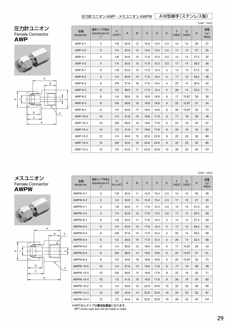
AW型継手(ステンレス製)圧力計ユニオンAWP・メスユニオンAWPW
圧力計ユニオンFemale ConnectorAWP
(unit:mm)
型番Model No.
適用パイプ外径φApplicable pipe O.D.
T
PG(PF) A B C D E F
(HEX)G
(HEX) H質量(g)Mass
AWP-3-1 3 1/8 32.9 12 15.9 13.4 2.5 14 12 26 27
AWP-3-2 3 1/4 33.9 15 15.9 13.4 2.5 17 12 27 35
AWP-4-1 4 1/8 34.8 12 17.8 15.3 3.5 14 14 27.5 32
AWP-4-2 4 1/4 35.8 15 17.8 15.3 3.5 17 14 28.5 36
AWP-6-1 6 1/8 34.9 12 17.9 15.4 5 14 14 27.5 30
AWP-6-2 6 1/4 35.9 15 17.9 15.4 5 17 14 28.5 36
AWP-6-3 6 3/8 37.9 16 17.9 15.4 5 22 14 30.5 55
AWP-6-4 6 1/2 39.9 17 17.9 15.4 5 26 14 32.5 71
AWP-8-2 8 1/4 36.8 15 18.8 16.8 6 17 15.87 29 38
AWP-8-3 8 3/8 38.8 16 18.8 16.8 6 22 15.87 31 34
AWP-8-4 8 1/2 40.8 17 18.8 16.8 6 26 15.87 33 74
AWP-10-2 10 1/4 37.8 15 19.8 17.8 6 17 19 30 48
AWP-10-3 10 3/8 39.8 16 19.8 17.8 6 22 19 32 67
AWP-10-4 10 1/2 41.8 17 19.8 17.8 8 26 19 34 83
AWP-12-2 12 1/4 40.8 15 22.8 22.8 6 22 23 30 89
AWP-12-3 12 3/8 42.8 16 22.8 22.8 6 22 23 32 85
AWP-12-4 12 1/2 44.8 17 22.8 22.8 10 26 23 34 101
メスユニオンFemale ConnectorAWPW
(unit:mm)
型番Model No.
適用パイプ外径φApplicable pipe O.D.
T
P(Rc or NPT) A B C D E F
(HEX)G
(HEX) H質量(g)Mass
AWPW-3-1 3 1/8 32.9 11 15.9 13.4 2.5 14 12 26 28
AWPW-3-2 3 1/4 33.9 13 15.9 13.4 2.5 17 12 27 35
AWPW-4-1 4 1/8 34.8 11 17.8 15.3 3.5 14 14 27.5 33
AWPW-4-2 4 1/4 35.8 13 17.8 15.3 3.5 17 14 28.5 39
AWPW-6-1 6 1/8 34.9 11 17.9 15.4 5 14 14 27.5 29
AWPW-6-2 6 1/4 35.9 13 17.9 15.4 5 17 14 28.5 44
AWPW-6-3 6 3/8 37.9 14 17.9 15.4 5 22 14 30.5 58
AWPW-6-4 6 1/2 39.9 19 17.9 15.4 5 26 14 32.5 69
AWPW-8-2 8 1/4 36.8 13 18.8 16.8 6 17 15.87 29 43
AWPW-8-3 8 3/8 38.8 14 18.8 16.8 6 22 15.87 31 61
AWPW-8-4 8 1/2 40.8 19 18.8 16.8 6 26 15.87 33 73
AWPW-10-2 10 1/4 37.8 13 19.8 17.8 8 17 19 30 49
AWPW-10-3 10 3/8 39.8 14 19.8 17.8 8 22 19 32 71
AWPW-10-4 10 1/2 41.8 19 19.8 17.8 8 26 19 34 83
AWPW-12-2 12 1/4 40.8 13 22.8 22.8 10 22 23 30 90
AWPW-12-3 12 3/8 42.8 14 22.8 22.8 10 22 23 32 87
AWPW-12-4 12 1/2 44.8 19 22.8 22.8 10 26 23 34 101
※NPTねじタイプは受注生産品になります。 NPT screw type size will be made to order.
ステンレス製締付継手.indd 29 14/01/27 9:27
29
AW型継手(ステンレス製)圧力計ユニオンAWP・メスユニオンAWPW
圧力計ユニオンFemale ConnectorAWP
(unit:mm)
型番Model No.
適用パイプ外径φApplicable pipe O.D.
T
PG(PF) A B C D E F
(HEX)G
(HEX) H質量(g)Mass
AWP-3-1 3 1/8 32.9 12 15.9 13.4 2.5 14 12 26 27
AWP-3-2 3 1/4 33.9 15 15.9 13.4 2.5 17 12 27 35
AWP-4-1 4 1/8 34.8 12 17.8 15.3 3.5 14 14 27.5 32
AWP-4-2 4 1/4 35.8 15 17.8 15.3 3.5 17 14 28.5 36
AWP-6-1 6 1/8 34.9 12 17.9 15.4 5 14 14 27.5 30
AWP-6-2 6 1/4 35.9 15 17.9 15.4 5 17 14 28.5 36
AWP-6-3 6 3/8 37.9 16 17.9 15.4 5 22 14 30.5 55
AWP-6-4 6 1/2 39.9 17 17.9 15.4 5 26 14 32.5 71
AWP-8-2 8 1/4 36.8 15 18.8 16.8 6 17 15.87 29 38
AWP-8-3 8 3/8 38.8 16 18.8 16.8 6 22 15.87 31 34
AWP-8-4 8 1/2 40.8 17 18.8 16.8 6 26 15.87 33 74
AWP-10-2 10 1/4 37.8 15 19.8 17.8 6 17 19 30 48
AWP-10-3 10 3/8 39.8 16 19.8 17.8 6 22 19 32 67
AWP-10-4 10 1/2 41.8 17 19.8 17.8 8 26 19 34 83
AWP-12-2 12 1/4 40.8 15 22.8 22.8 6 22 23 30 89
AWP-12-3 12 3/8 42.8 16 22.8 22.8 6 22 23 32 85
AWP-12-4 12 1/2 44.8 17 22.8 22.8 10 26 23 34 101
メスユニオンFemale ConnectorAWPW
(unit:mm)
型番Model No.
適用パイプ外径φApplicable pipe O.D.
T
P(Rc or NPT) A B C D E F
(HEX)G
(HEX) H質量(g)Mass
AWPW-3-1 3 1/8 32.9 11 15.9 13.4 2.5 14 12 26 28
AWPW-3-2 3 1/4 33.9 13 15.9 13.4 2.5 17 12 27 35
AWPW-4-1 4 1/8 34.8 11 17.8 15.3 3.5 14 14 27.5 33
AWPW-4-2 4 1/4 35.8 13 17.8 15.3 3.5 17 14 28.5 39
AWPW-6-1 6 1/8 34.9 11 17.9 15.4 5 14 14 27.5 29
AWPW-6-2 6 1/4 35.9 13 17.9 15.4 5 17 14 28.5 44
AWPW-6-3 6 3/8 37.9 14 17.9 15.4 5 22 14 30.5 58
AWPW-6-4 6 1/2 39.9 19 17.9 15.4 5 26 14 32.5 69
AWPW-8-2 8 1/4 36.8 13 18.8 16.8 6 17 15.87 29 43
AWPW-8-3 8 3/8 38.8 14 18.8 16.8 6 22 15.87 31 61
AWPW-8-4 8 1/2 40.8 19 18.8 16.8 6 26 15.87 33 73
AWPW-10-2 10 1/4 37.8 13 19.8 17.8 8 17 19 30 49
AWPW-10-3 10 3/8 39.8 14 19.8 17.8 8 22 19 32 71
AWPW-10-4 10 1/2 41.8 19 19.8 17.8 8 26 19 34 83
AWPW-12-2 12 1/4 40.8 13 22.8 22.8 10 22 23 30 90
AWPW-12-3 12 3/8 42.8 14 22.8 22.8 10 22 23 32 87
AWPW-12-4 12 1/2 44.8 19 22.8 22.8 10 26 23 34 101
※NPTねじタイプは受注生産品になります。 NPT screw type size will be made to order.
ステンレス製締付継手.indd 29 14/01/27 9:27

30
AW型継手(ステンレス製)
AW
袋ナット AWN・フェルール(フロント) AWFF・フェルール(リア) AWFR
袋ナットCap NutAWN
(unit:mm)
型番Model No.
適用パイプ外径φApplicable pipe O.D.
T
G(HEX) L
質量(g)Mass
AWN-3 3 12 12 9
AWN-4 4 14 12.5 10
AWN-6 6 14 12.5 9
AWN-8 8 15.87 13.5 13
AWN-10 10 19 15 18
AWN-12 12 23 17.5 30
フェルール(フロント)Front FerruleAWFF
フェルール(リア)Rear FerruleAWFR
(unit:mm)
型番Model No.
適用パイプ外径φApplicable pipe O.D.
T
質量(g)Mass
AWFF-3 3 0.4
AWFF-4 4 0.5
AWFF-6 6 0.7
AWFF-8 8 0.9
AWFF-10 10 1.1
AWFF-12 12 3.0
(unit:mm)
型番Model No.
適用パイプ外径φApplicable pipe O.D.
T
質量(g)Mass
AWFR-3 3 0.2
AWFR-4 4 0.3
AWFR-6 6 0.4
AWFR-8 8 0.5
AWFR-10 10 0.6
AWFR-12 12 1.2
ステンレス製締付継手.indd 30 14/01/27 9:27
31
AW型継手(ステンレス製) インサートリング AWI・PTパネル(ステンレス製) DAW-00-SUS
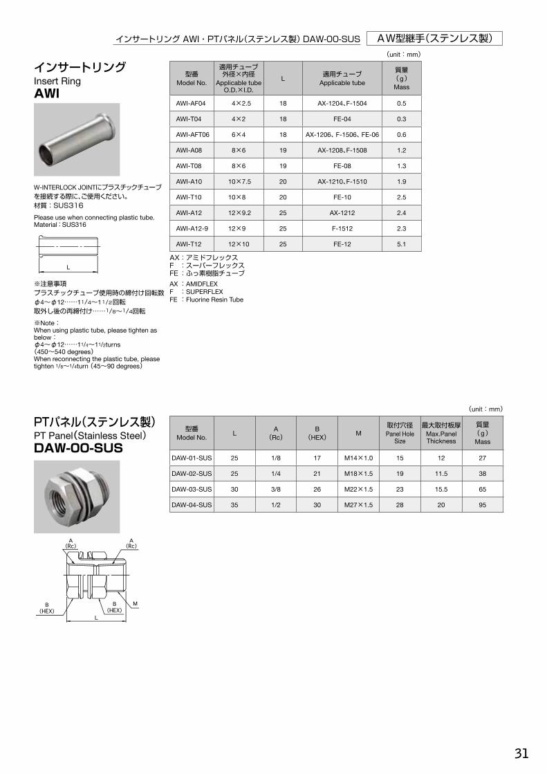
インサートリングInsert RingAWI
PTパネル(ステンレス製)PT Panel(Stainless Steel) DAW-00-SUS
(unit:mm)
型番Model No.
適用チューブ外径×内径
Applicable tubeO.D.×I.D.
L 適用チューブApplicable tube
質量(g)Mass
AWI-AF04 4×2.5 18 AX-1204、F-1504 0.5
AWI-T04 4×2 18 FE-04 0.3
AWI-AFT06 6×4 18 AX-1206、F-1506、FE-06 0.6
AWI-A08 8×6 19 AX-1208、F-1508 1.2
AWI-T08 8×6 19 FE-08 1.3
AWI-A10 10×7.5 20 AX-1210、F-1510 1.9
AWI-T10 10×8 20 FE-10 2.5
AWI-A12 12×9.2 25 AX-1212 2.4
AWI-A12-9 12×9 25 F-1512 2.3
AWI-T12 12×10 25 FE-12 5.1
AX:アミドフレックスF :スーパーフレックスFE :ふっ素樹脂チューブAX :AMIDFLEXF :SUPERFLEXFE :Fluorine Resin Tube
(unit:mm)
型番Model No. L A
(Rc)B
(HEX) M取付穴径Panel Hole
Size
最大取付板厚Max.Panel Thickness
質量(g)Mass
DAW-01-SUS 25 1/8 17 M14×1.0 15 12 27
DAW-02-SUS 25 1/4 21 M18×1.5 19 11.5 38
DAW-03-SUS 30 3/8 26 M22×1.5 23 15.5 65
DAW-04-SUS 35 1/2 30 M27×1.5 28 20 95
W-INTERLOCK JOINTにプラスチックチューブを接続する際に、ご使用ください。材質:SUS316
Please use when connecting plastic tube.Material:SUS316
※注意事項プラスチックチューブ使用時の締付け回転数φ4~φ12……11/4~11/2回転取外し後の再締付け……1/8~1/4回転
※Note:When using plastic tube, please tighten as below:φ4~φ12……11/4~11/2turns
(450~540 degrees)When reconnecting the plastic tube, please tighten 1/8~1/4turn (45~90 degrees)
ステンレス製締付継手.indd 31 14/01/27 9:27
31
AW型継手(ステンレス製) インサートリング AWI・PTパネル(ステンレス製) DAW-00-SUS
インサートリングInsert RingAWI
PTパネル(ステンレス製)PT Panel(Stainless Steel) DAW-00-SUS
(unit:mm)
型番Model No.
適用チューブ外径×内径
Applicable tubeO.D.×I.D.
L 適用チューブApplicable tube
質量(g)Mass
AWI-AF04 4×2.5 18 AX-1204、F-1504 0.5
AWI-T04 4×2 18 FE-04 0.3
AWI-AFT06 6×4 18 AX-1206、F-1506、FE-06 0.6
AWI-A08 8×6 19 AX-1208、F-1508 1.2
AWI-T08 8×6 19 FE-08 1.3
AWI-A10 10×7.5 20 AX-1210、F-1510 1.9
AWI-T10 10×8 20 FE-10 2.5
AWI-A12 12×9.2 25 AX-1212 2.4
AWI-A12-9 12×9 25 F-1512 2.3
AWI-T12 12×10 25 FE-12 5.1
AX:アミドフレックスF :スーパーフレックスFE :ふっ素樹脂チューブAX :AMIDFLEXF :SUPERFLEXFE :Fluorine Resin Tube
(unit:mm)
型番Model No. L A
(Rc)B
(HEX) M取付穴径Panel Hole
Size
最大取付板厚Max.Panel Thickness
質量(g)Mass
DAW-01-SUS 25 1/8 17 M14×1.0 15 12 27
DAW-02-SUS 25 1/4 21 M18×1.5 19 11.5 38
DAW-03-SUS 30 3/8 26 M22×1.5 23 15.5 65
DAW-04-SUS 35 1/2 30 M27×1.5 28 20 95
W-INTERLOCK JOINTにプラスチックチューブを接続する際に、ご使用ください。材質:SUS316
Please use when connecting plastic tube.Material:SUS316
※注意事項プラスチックチューブ使用時の締付け回転数φ4~φ12……11/4~11/2回転取外し後の再締付け……1/8~1/4回転
※Note:When using plastic tube, please tighten as below:φ4~φ12……11/4~11/2turns
(450~540 degrees)When reconnecting the plastic tube, please tighten 1/8~1/4turn (45~90 degrees)
ステンレス製締付継手.indd 31 14/01/27 9:27

32
AW型継手(ステンレス製)
AW
ミニチュアバルブ(H型) AWVH
(unit:mm)
型番Model No.
適用パイプ外径φApplicable pipe O.D.
T
PR(PT) A B C1
(φ)C2
(φ) D E F(HEX)
G(HEX) H I
取付穴径Panel Hole
Size
質量(g)Mass
AWVH-4-1 4 1/8 28.8 11 30 22 15.3 2.6 17 14 51 22 14.5 125
AWVH-6-2 6 1/4 28.9 13 30 22 15.4 3 17 14 51 25 14.5 127
AWVH-8-2 8 1/4 29.8 13 30 22 16.8 3 17 15.87 51 25 14.5 133
AWVH-10-2 10 1/4 30.8 13 30 22 17.8 3 17 19 51 25 14.5 141
No. 名称Part Name
材質Material Q'TY
① 本体Body SUS316 1
② スピンドルSpindle SUS316 1
③ OリングO Ring VITON 1
④ バックアップリングBack Up Ring PTFE 1
⑤ グランドナットGrand Nut SUS304 1
⑥ ロックナットLock Nut C3604BD(Nilll) 1
⑦ ハンドルHandle C3604BD(Nilll) 1
⑧ 六角袋ナットDomed Cap Nut SUS304 1
⑨ 歯付座金Toothed Lock Washer SUS304 1
⑩ 銘板Nameplate A5052P 1
⑪ 袋ナットCap Nut SUS316 2
⑫ フェルール(リア)Rear Ferrule SUS316 2
⑬ フェルール(フロント)Front Ferrule SUS316 2
⑭ マウントナットMount Nut SUS304 1
ミニチュアバルブシリーズMiniature Valve Series
■ミニチュアバルブ使用条件 Miniature Valve Use Condition
● 使用温度:100℃以下 Working temperature:~100℃
● 使用圧力:2.0MPa以下 Working pressure range:~2.0MPa
■構造断面図 Internal Structure
ミニチュアバルブ(H型)Miniature Valve(H・Type)AWVH
ステンレス製締付継手.indd 32 14/01/27 9:27
33
AW型継手(ステンレス製)ミニチュアバルブ(S型) AWVS・ミニチュアバルブ(D型) AWVD・ミニチュアバルブ(L型) AWVL
(unit:mm)
型番Model No
適用パイプ外径φApplicable pipe O.D.
TA B C1
(φ)C2
(φ) D E F(HEX)
G(HEX) H
取付穴径Panel Hole
Size
質量(g)Mass
AWVL-4-0 4 29.3 29.3 30 22 15.3 3 17 14 50 14.5 134
AWVL-6-0 6 29.4 29.4 30 22 15.4 3 17 14 50 14.5 105
AWVL-8-0 8 29.8 29.8 30 22 16.8 3 17 15.87 50 14.5 136
AWVL-10-0 10 30.8 30.8 30 22 17.8 3 17 19 50 14.5 158
(unit:mm)
型番Model No.
適用パイプ外径φApplicable pipe O.D.
T
R(PT) A B C1
(φ)C2
(φ) D E F(HEX)
G(HEX) H I
取付穴径Panel Hole
Size
質量(g)Mass
AWVD-4-1 4 1/8 23 11 30 22 15.3 3 17 14 50 29.3 14.5 124
AWVD-6-2 6 1/4 25 13 30 22 15.4 3 17 14 50 29.4 14.5 128
AWVD-8-2 8 1/4 25 13 30 22 16.8 3 17 15.87 50 29.8 14.5 130
AWVD-10-2 10 1/4 25 13 30 22 17.8 3 17 19 50 30.8 14.5 141
(unit:mm)
型番Model No.
適用パイプ外径φApplicable pipe O.D.
TA C1
(φ)C2
(φ) D E F(HEX)
G(HEX) H
取付穴径Panel Hole
Size
質量(g)Mass
AWVS-4-0 4 57.6 30 22 15.3 2.6 17 14 51 14.5 138
AWVS-6-0 6 57.8 30 22 15.4 3 17 14 51 14.5 132
AWVS-8-0 8 59.6 30 22 16.8 3 17 15.87 51 14.5 140
AWVS-10-0 10 61.6 30 22 17.8 3 17 19 51 14.5 158
ミニチュアバルブ(S型)Miniature Valve(S・Type) AWVS
ミニチュアバルブ(D型)Miniature Valve(D・Type) AWVD
ミニチュアバルブ(L型)Miniature Valve(L・Type) AWVL
ステンレス製締付継手.indd 33 14/01/27 9:27
34
AW
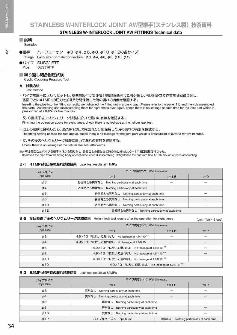
■試料 Samples
■繰り返し結合耐圧試験 Cyclic Coupling Pressure Test
●継手 ハーフユニオン φ3、φ4、φ6、φ8、φ10、φ12の各サイズ Fittings Each size for male connectors : φ3, φ4, φ6, φ8, φ10, φ12●パイプ SUS316TP Pipe SUS316TP
A 試験方法 Test method
・パイプを継手に正しくセットし、基準締め付けで(P21参照)締め付けた後分解し、再び組み立て作業を8回繰り返し、 各回ごとに41MPaの圧力を加え5分間保持した時の漏れの有無を確認する。 Inserting the pipe into the fitting correctly, we tightened the fitting nut in a basic way (Please refer to the page, 21) and then disassembled the parts. Assembling and disassembling them for eight times over again, check there is no leakage at each time for the joint part which is pressurized at 41MPa for five minutes.
・又、8回終了後、ヘリウムリーク試験に於いて漏れの有無を確認する。 Finishing the operation above for eight times, check there is no leakage at the helium leak test.
・以上の試験に合格したら、82MPaの圧力を加え5分間保持した時の漏れの有無を確認する。 The fitting having passed the test above, check there is no leakage for the joint part which is pressurized at 82MPa for five minutes.
・又、その後のヘリウムリーク試験に於いて漏れの有無を確認する。 Check there is no leakage at the helium leak test afterwards.
※分解は各回ごとパイプを継手本体から取り外し、各回ごとの組み立て時の増し締めは、0~1/16回転程度行なった。 Removed the pipe from the fitting body at each time when disassembling. Retightened the nut from 0 to 1/16th around at each assembling.
STAINLESS W-INTERLOCK JOINT AW型継手(ステンレス製) 技術資料STAINLESS W-INTERLOCK JOINT AW FITTINGS Technical data
B-1 41MPa加圧時の漏れ試験結果 Leak test results at 41MPa
パイプサイズPipe Size
パイプ肉厚(mm) Wall thickness
t=1 t=1.5 t=2
φ3 各回時とも異常なし Nothing particularly at each time ― ―
φ4 各回時とも異常なし Nothing particularly at each time ― ―
φ6 各回時とも異常なし Nothing particularly at each time ―
φ8 各回時とも異常なし Nothing particularly at each time ―
φ10 各回時とも異常なし Nothing particularly at each time ―
φ12 各回時とも異常なし Nothing particularly at each time
B-2 8回時終了後のヘリウムリーク試験結果 Helium leak test results after the operation for eight times (unit:Torr・ℓ/sec)
パイプサイズPipe Size
パイプ肉厚(mm) Wall thickness
t=1 t=1.5 t=2
φ3 4.9×10⁻¹¹に於いて漏れなし No leakage at 4.9×10⁻¹¹ ― ―
φ4 4.9×10⁻¹¹に於いて漏れなし No leakage at 4.9×10⁻¹¹ ― ―
φ6 4.9×10⁻¹¹に於いて漏れなし No leakage at 4.9×10⁻¹¹ ―
φ8 4.9×10⁻¹¹に於いて漏れなし No leakage at 4.9×10⁻¹¹ ―
φ10 4.9×10⁻¹¹に於いて漏れなし No leakage at 4.9×10⁻¹¹ ―
φ12 4.9×10⁻¹¹に於いて漏れなし No leakage at 4.9×10⁻¹¹
B-3 82MPa加圧時の漏れ試験結果 Leak test results at 82MPa
パイプサイズPipe Size
パイプ肉厚(mm) Wall thickness
t=1 t=1.5 t=2
φ3 異常なし Nothing particularly at each time ― ―
φ4 異常なし Nothing particularly at each time ― ―
φ6 異常なし Nothing particularly at each time ―
φ8 異常なし Nothing particularly at each time ―
φ10 異常なし Nothing particularly at each time ―
φ12 パイプがバースト Pipe burst 異常なし Nothing particularly at each time
ステンレス製締付継手.indd 34 14/01/27 9:27
35
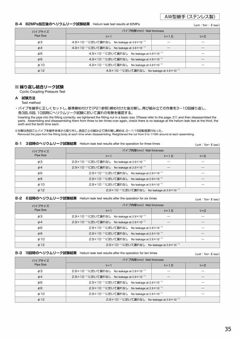
AW型継手(ステンレス製)
■繰り返し結合リーク試験 Cyclic Coupling Pressure Test
A 試験方法 Test method・パイプを継手に正しくセットし、基準締め付けで(P21参照)締め付けた後分解し、再び組み立ての作業を3~10回繰り返し、 各3回、6回、10回時にヘリウムリーク試験に於いて漏れの有無を確認する。 Inserting the pipe into the fitting correctly, we tightened the fitting nut in a basic way (Please refer to the page, 21) and then disassembled the
parts. Assembling and disassembling them from three to ten times over again, check there is no leakage at the helium leak test at the third, the sixth and the tenth time each.
※分解は各回ごとパイプを継手本体から取り外し、各回ごとの組み立て時の増し締めは、0~1/16回転程度行なった。 Removed the pipe from the fitting body at each time when disassembling. Retightened the nut from 0 to 1/16th around at each assembling.
B-1 3回時のヘリウムリーク試験結果 Helium leak test results after the operation for three times (unit:Torr・ℓ/sec)
パイプサイズPipe Size
パイプ肉厚(mm) Wall thickness
t=1 t=1.5 t=2
φ3 2.9×10⁻¹¹に於いて漏れなし No leakage at 2.9×10⁻¹¹ ― ―
φ4 2.9×10⁻¹¹に於いて漏れなし No leakage at 2.9×10⁻¹¹ ― ―
φ6 2.9×10⁻¹¹に於いて漏れなし No leakage at 2.9×10⁻¹¹ ―
φ8 2.9×10⁻¹¹に於いて漏れなし No leakage at 2.9×10⁻¹¹ ―
φ10 2.9×10⁻¹¹に於いて漏れなし No leakage at 2.9×10⁻¹¹ ―
φ12 2.9×10⁻¹¹に於いて漏れなし No leakage at 2.9×10⁻¹¹
B-2 6回時のヘリウムリーク試験結果 Helium leak test results after the operation for six times (unit:Torr・ℓ/sec)
パイプサイズPipe Size
パイプ肉厚(mm) Wall thickness
t=1 t=1.5 t=2
φ3 2.9×10⁻¹¹に於いて漏れなし No leakage at 2.9×10⁻¹¹ ― ―
φ4 2.9×10⁻¹¹に於いて漏れなし No leakage at 2.9×10⁻¹¹ ― ―
φ6 2.9×10⁻¹¹に於いて漏れなし No leakage at 2.9×10⁻¹¹ ―
φ8 2.9×10⁻¹¹に於いて漏れなし No leakage at 2.9×10⁻¹¹ ―
φ10 2.9×10⁻¹¹に於いて漏れなし No leakage at 2.9×10⁻¹¹ ―
φ12 2.9×10⁻¹¹に於いて漏れなし No leakage at 2.9×10⁻¹¹
B-3 10回時のヘリウムリーク試験結果 Helium leak test results after the operation for ten times (unit:Torr・ℓ/sec)
パイプサイズPipe Size
パイプ肉厚(mm) Wall thickness
t=1 t=1.5 t=2
φ3 2.9×10⁻¹¹に於いて漏れなし No leakage at 2.9×10⁻¹¹ ― ―
φ4 2.9×10⁻¹¹に於いて漏れなし No leakage at 2.9×10⁻¹¹ ― ―
φ6 2.9×10⁻¹¹に於いて漏れなし No leakage at 2.9×10⁻¹¹ ―
φ8 2.9×10⁻¹¹に於いて漏れなし No leakage at 2.9×10⁻¹¹ ―
φ10 2.9×10⁻¹¹に於いて漏れなし No leakage at 2.9×10⁻¹¹ ―
φ12 2.9×10⁻¹¹に於いて漏れなし No leakage at 2.9×10⁻¹¹
B-4 82MPa加圧後のヘリウムリーク試験結果 Helium leak test results at 82MPa (unit:Torr・ℓ/sec)
パイプサイズPipe Size
パイプ肉厚(mm) Wall thickness
t=1 t=1.5 t=2
φ3 4.9×10⁻¹¹に於いて漏れなし No leakage at 4.9×10⁻¹¹ ― ―
φ4 4.9×10⁻¹¹に於いて漏れなし No leakage at 4.9×10⁻¹¹ ― ―
φ6 4.9×10⁻¹¹に於いて漏れなし No leakage at 4.9×10⁻¹¹ ―
φ8 4.9×10⁻¹¹に於いて漏れなし No leakage at 4.9×10⁻¹¹ ―
φ10 4.9×10⁻¹¹に於いて漏れなし No leakage at 4.9×10⁻¹¹ ―
φ12 4.9×10⁻¹¹に於いて漏れなし No leakage at 4.9×10⁻¹¹
ステンレス製締付継手.indd 35 14/01/27 9:27

36
AW型継手(ステンレス製)
AW
■破壊圧試験 Bursting Pressure Test
A 試験方法 Test method
・繰り返し結合耐圧試験に合格した継手に破壊圧を加え、継手部の異常の有無を確認するとともに破壊圧値を測定する。 Applying the bursting pressure to the fitting which passed the cyclic coupling pressure test, check there is nothing wrong for the joint part and
measure the bursting pressure value for it.
B 試験結果 Test results (unit:MPa)
パイプサイズPipe Size
破壊圧平均値Bursting pressure value
状況Situation
φ3 370 パイプがバースト pipe burst
φ4 280 パイプがバースト pipe burst
φ6 179 パイプがバースト pipe burst
φ8 132 パイプがバースト pipe burst
φ10 96 パイプがバースト pipe burst
φ12 84 パイプがバースト pipe burst
(unit:mm)
パイプ外径Pipe O.D. φ3 φ4 φ6 φ8 φ10 φ12
パイプの肉厚Wall thickness 1 1 1 1 1 1
・全てのパイプがバーストし継手部に漏れ、抜け等の異常は確認されなかった。 All pipes having been burst, nothing particularly could be seen such as the leakage or pipes pulled out for the joint part.
■引張り試験 Tensile Test
A 試験方法 Test method
・継手を基準締め付け回転数(P21参照)にて組み立て、その後引張り試験機にて引張りを加えて破壊状態を確認する。 Installing the fitting with the tensile device, being the nut tightened in a basic way (Please refer to the page, 21) check the destruction condition
by pulling the tube as the figure shows on the right.
B 試験結果 Test results (unit:N)
パイプサイズPipe Size
パイプ種類 Pipe type
引張り強度平均値 Tensile strength average 状況 Situation
φ3 2700 全てパイプ離脱 All pipes removed
φ4 3800 全てパイプ離脱 All pipes removed
φ6 6300 全てパイプ離脱 All pipes removed
φ8 6600 全てパイプ離脱 All pipes removed
φ10 10200 全てパイプ離脱 All pipes removed
φ12 12000 全てパイプ離脱 All pipes removed
・試験機「最大測定2ton」 Testing equipment "Maximum measurement up to 2tons"
・各試料とも全て基準数値をクリアした。 Each sample satisfied the reference value.
Load meter
Load cell
Sample fitting
Pipe
ステンレス製締付継手.indd 36 14/01/27 9:27
37
AW型継手(ステンレス製)■耐衝撃圧試験 Shock Resistant Test
■耐振動試験 Vibration Resistance Test
A 試験方法 Test method・インパルステスターにて衝撃圧定格圧力20.6MPaの150±7%とし、周波数は30~75サイクル/min
とする。 Applying the rated pressure 20.6MPa (150±7%) to the fittings with an impulse tester and the cyclic frequency
for it from 30 to 75/min.
・20万衝撃サイクル試験を行ない、漏れ及び継手部破損の有無を調べる。 Check there is no leakage or breakage for the joint part after we perform the cyclic shock test for it at 200,000
times.※使用パイプは繰り返し結合試験と同一サイズとする。 The pipe is the same size as the one used for the cyclic tests above.
B 試験結果 Test results・各試料とも、いずれも異常は認められなかった。 Nothing particularly could be seen for each sample.
A 試験方法 Test method・下図のように、組み立てた継手の固定端に曲げ応力が生じるような繰り返し荷重を1,400サイクル/min以上の割合で加え、 同時に定格圧力(20.6MPa)を加えて、1,000万回振動サイクル後に漏れ及び継手部の破損の有無を調べる。 As the figure shows below, we applied the cyclic pressure to one end of the pipe which might bend at more than 1400 cycles/min. and
pressurized it inside at 20.6MPa at the same time. And check there is no leakage or breakage for the joint part after we vibrate the parts at 10,000,000 times.
※曲げ応力はφ3~φ12まで98N/mm2とする。 The bending stress φ3 toφ12 : 98N/mm2
※使用パイプは繰り返し結合試験と同一サイズとする。 The pipe is the same size as the one used for the cyclic tests above.
長さ(L)と変位(σ)との計算式 Formula between length and displacement
E:パイプ材料の縦弾性係数(2.1×10⁵N/mm²) Young's modulus for pipe material (2.1×10⁵N/mm2)
e:パイプ外径の1/2(mm) Pipe outside diameter (1/2(mm))
:曲げ応力(N/mm2) Bending stress(N/mm2)
B 試験結果 Test results
・各試料とも、いずれも異常は認められなかった。Nothing particularly could be seen for each sample.
Plug
Sample fitting
Pressure
Pressure
Sample fitting
Fixed end Pipe(SUS)(e) Load action point
Displacement( )
Length(L)
ステンレス製締付継手.indd 37 14/01/27 9:27