stainless steel heavy-duty submersible pumps - grundfosnotesfile/sen... · – stainless steel pump...
TRANSCRIPT

GRUNDFOS WASTEWATER
Stainless steel heavy-dutysubmersible pumps

Grundfos SEN Range
Grundfos offers a full range of extremely depend-
able wastewater pumps, made entirely or partly
of high-grade stainless steel. These powerful
pumps are built for handling aggressive waste-
water, process water, and unscreened raw sewage
in aggressive environments.
The stainless steel pumps are available in three
different versions: Version R, made entirely of
stainless steel; version S, where the pump hous-
ing, flange and impeller are stainless steel; and
version Q, where only the impeller is stainless
steel.
> 2
Stainless steel submersible pumpsfor aggressive environments
Powerful advantages
> Higher pump efficiency over time
State-of-the-art technology makes the Grundfos
pumps extremely efficient and highly dependable.
Innovative features such as the unique SmartTrim
adjustment of impeller clearance provide low
life cycle costs.
> Less downtime
The inherent non-clogging design of our Super-
Vortex impeller pumps and the excellent solids
handling capability of our channel impeller pumps
guarantee maximum operating time and sub-
stantial reductions in maintenance costs caused
by pump blockage or clogging.
> Lifelong reliability
The stainless steel pumps are of a very sturdy
construction, designed for continuous pumping
under the most difficult operating conditions.
The well-proven design is based on our long ex-
perience in the wastewater business.
At Grundfos we maintain a close dialogue with
our customers in order to constantly improve our
pump designs and performance. Only in this
way can we build the long-lasting relationships
on which our business is founded.

> 3
Installation options
Submerged installationFor submerged installation with auto-coupling system, a base unit with
a 90-degree bend, fixed to the bottom of the pit, is required. The pump is
lowered into the pit along two guide rails. The pump automatically connects
to the base unit, and, on the discharge side of the pump, a flexible neoprene
seal – SmartSeal – ensures a leak-proof connection between the pump and
the auto-coupling.
Vertical dry installation The Grundfos submersible wastewater pumps can be installed either
vertically or horizontally to suit specific application arrangements.
All pump models are 100% watertight, which allows for dry installation
where the workspace surrounding the pump remains clean and dry.
However, the pumps are fully flood-proof if the unexpected should occur.
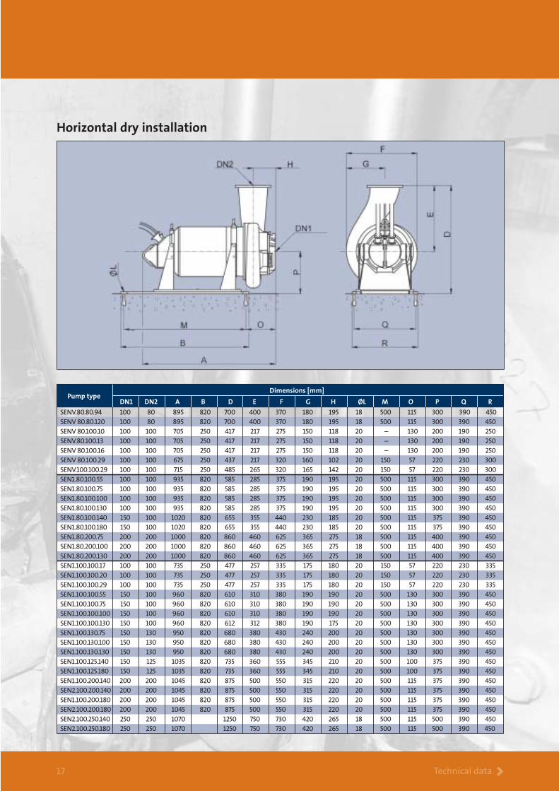
Horizontal dry installationFor reduced operating and installation costs, horizontal dry installation
improves the overall efficiency of the system as unnecessary components
and bends are avoided. The feasibility of horizontal dry installation, how-
ever, depends on the floor space available as the system takes up slightly
more room than a vertically installed pump.
Portable submerged application Certain applications require portable submersible pumps, for instance for
emergency use in industry. Where a portable submersible pump is required,
hoses of varying lengths and materials can be supplied.
Depending on the application, the Grundfos range of stainless
steel submersible wastewater pumps is available for submerged
or dry installation, or portable use as required.

Applications >4
Industrial effluent
The Grundfos stainless steel wastewater pumps are
ideal for use in industrial applications where aggres-
sive or corrosive liquids are encountered. The stainless
steel parts are made of high-grade steel of DIN/EN
1.4408, 1.4460 or 1.4436 qualities. This makes the
pumps suitable for a variety of acidic and corrosive
liquids including environments with salt water influx.
Explosion-proof motorsThe stainless steel wastewater pumps are available
with explosion-proof motors for applications involv-
ing a high risk of explosion. For transfer of high-
temperature liquids the pumps can be installed with
cooling jackets fitted for external cooling water.
Version S– stainless steel
pump housing,
flange and
impeller. Cast
iron motor.
Version Q– stainless steel
impeller. Cast
iron pump
and motor
housing.
Version R– made entirely
of corrosion-
resistant stain-
less steel.
The Grundfos stainless steel wastewater pumps are available in three basic versions:

5 Applications >5
Typical applications
Picture 1 shows one of two Grundfos stainless steel
pumps used for pumping pigment-containing chan-
nel water with a density of 1.0 - 1.4 kg/dm3 and a
maximum viscosity of 250 mPas. Both pumps are
fitted with the patented shaft seal flushing system.
The pictures show two typical industrial applications
Picture 2 shows one of two Grundfos stainless steel
pumps used at a glass wool manufacturing plant for
pumping process water with a high content of
abrasive particles. Both these pumps are also fitted
with the efficient shaft seal flushing system.
Shaft seal flushing systemFor applications involving particularly abrasive or
sticky liquids, the stainless steel wastewater pumps
can be fitted with a unique patented shaft seal
flushing system. The system uses water from an
external source.
The flushing system operates with a liquid pressure
0.5 bar higher than that of the pumped liquid. This
protects the shaft seal from excessive wear, while
preventing build-up of abrasives, which may lead
to seal failure and pump breakdown.
Controller
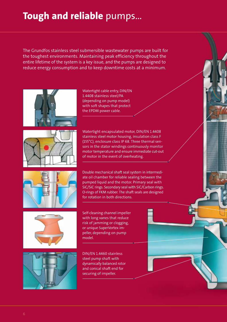
Watertight encapsulated motor, DIN/EN 1.4408
stainless steel motor housing, insulation class F
(155°C), enclosure class IP 68. Three thermal sen-
sors in the stator windings continuously monitor
motor temperature and ensure immediate cut-out
of motor in the event of overheating.
6
Tough and reliable pumps…
The Grundfos stainless steel submersible wastewater pumps are built for
the toughest environments. Maintaining peak efficiency throughout the
entire lifetime of the system is a key issue, and the pumps are designed to
reduce energy consumption and to keep downtime costs at a minimum.
Watertight cable entry, DIN/EN
1.4408 stainless steel/PA
(depending on pump model)
with soft shapes that protect
the EPDM power cable.
Double mechanical shaft seal system in intermedi-
ate oil chamber for reliable sealing between the
pumped liquid and the motor. Primary seal with
SiC/SiC rings. Secondary seal with SiC/Carbon rings.
O-rings of FKM rubber. The shaft seals are designed
for rotation in both directions.
Self-cleaning channel impeller
with long vanes that reduce
risk of jamming or clogging,
or unique SuperVortex im-
peller, depending on pump
model.
DIN/EN 1.4460 stainless
steel pump shaft with
dynamically balanced rotor
and conical shaft end for
securing of impeller.

Details > 7
– with many unique features
Moisture detector for
continuously monitoring
of motor enclosure.
Automatic power cut-off
in the event of leakage.
SmartTrim system for easy and quick
adjustment of impeller clearance without
dismantling the pump. This enables main-
taining of factory-set impeller clearance and
maximum pump efficiency. Adjustment is
done by turning three screws on the pump
housing. No special tools are required.
Auxiliary vanes at the bot-
tom of channel impellers
prevent back flow and
jamming between impeller
and pump housing.
DIN/EN 1.4408 stainless
steel pump housing
(depending on pump model,
see page 19 for details).
Heavy-duty maintenance-free
ball bearings, greased for life.
Lower bearing on all pump
models consists of double row
of ball bearings.

SuperVortex > 8
Grundfos SuperVortex
A unique impeller design
The unique design of the Grundfos SuperVortex
impellers provides high pumping efficiency and
less down time. With a flow range from 4 l/s,
the stainless steel Grundfos SuperVortex pumps
are the optimum solution for all smaller pump-
ing stations where aggressive or corrosive liquids
are encountered.
Full Q/H curve without operating limitations and vibrationsDue to the special power characteristics of the
Grundfos SuperVortex pumps, it is possible to
run the pumps from 4 l/s right up to the maxi-
mum flow on the curves without any risk of
overloading the motor. The steep performance
curve means minimal flow fluctuation with
varying heads.
No clogging or jammingIn a SuperVortex pump the flow takes place en-
tirely outside the impeller. The design of the im-
peller ensures that long fibres, rags, etc. pass freely
through the pumps without getting caught and
without causing clogging or jamming. This means
less downtime and, consequently, reduced service
costs and higher pumping efficiency.
The design of the SuperVortex pumps also pre-
vents the common problem of jamming between
wear rings. A Grundfos SuperVortex pump needs
no wear rings!
Conventional vortex impellerIn pumps fitted with a conventional vortex impeller,
turbulent disturbance is liable to form around the
impeller. This will disrupt the flow pattern and result
in lower pumping efficiency and reduced head.
Grundfos SuperVortex impellerThe liquid passes freely outside the impeller
without any turbulent disturbance.

Channel Impellers > 9
Grundfos channel impellers
Efficient non-clogging
The Grundfos stainless steel channel-impeller
pumps provide high efficiency and excellent non-
clogging capabilities. The channel impellers are
designed with a large free passage – 80 mm or
100 mm, depending on model – and long im-
peller vanes. Channel-impeller pumps are ideal for
heavy-duty operation in larger pumping stations.
Large free passage for superior solids handlingCompromising on the ability to handle solids, in
order to obtain higher pumping efficiency, sub-
stantially increases the risk of clogging. More
clogging means more downtime and increased
operating costs.
The Grundfos channel-impeller pumps are capable
of handling solids of up to 80 mm or 100 mm size.
The full free passage, however, is much larger.
The result is less clogging and less downtime.
Semi-axial impeller design with long vaneThe length of an impeller vane is a key factor in
determining the length of fibres that may pass
through a pump without getting caught. The
Grundfos channel impellers are of a semi-axial
design with extra long vanes. This provides maxi-
mum performance and eliminates problems with
fibres or rags getting caught in the impeller.
Self-cleaning impeller On Grundfos wastewater pumps smaller than
12 kW, the bottom part of the channel impellers
feature specially designed auxiliary vanes. These
vanes are designed to create a powerful flow
that keeps the clearance between the impeller
and the pump housing free from solids or fibres.

Technical data > 10
Performance overview and type key
Performance overview – stainless steel submersible wastewater pumps
Type key – stainless steel submersible wastewater pumps
4 6 10 15 20 40 60 100 150 200 Q [l/s]
2
3
4
6
10
15
20
30
40
60
H
[m]
20 40 60 80 100 200 400 600 Q [m3/h]
SEN Range
50 HzSuperVortex impeller pumps
Channel impeller pumps
Example SEN1.100.100.130.D.Ex.4.511.Q SE N 1 .100 .100 .130 .D .Ex 4 .511 Q
Pump range
N = Stainless steel
Impeller type
1 = Figures indicate channel impellers and
the number indicates the number of channels
V = SuperVortex
Maximum solids size [mm]
Nominal diameter of discharge port [mm]
Motor power output P2 / 100 [W]
Installation
Blank = Without cooling jacket
D = With cooling jacket
Version
Blank = Non-explosion-proof
Ex = Explosion-proof
Number of poles
Frequency, voltage and starting method
511 = 50 Hz, 400 V, star-delta starting. The first digit indicates the frequency and the next two digits indicate the voltage and starting method.
5 = 50 Hz
01 = 400 V, direct-on-line starting
11 = 400 V, star-delta starting
Generation
Blank = First generation (A)
B = Second generation
C = Third generation, etc.
Pump materials
R = Pump and motor of stainless steel, DIN W.-Nr. 1.4408
S = Hydraulic parts of stainless steel, DIN W.-Nr. 1.4408
Q = Cast-iron pump with stainless steel impeller, DIN W.-Nr. 1.4408

Technical data > 11
SuperVortex pumps
SuperVortex performance overview
0 4 8 12 16 20 24 28 32 36 40 Q [l/s]
0
5
10
15
20
25
30
35
40
45
50
55
60
H
[m]
0 20 40 60 80 100 120 140 Q [m3/h]
SENV.80.80SENV.100.100
50 HzISO 9906 Annex A
80.80.210
80.80.150
80.80.12080.80.94
80.80.74
100.100.42100.100.29
0 4 8 12 16 20 24 28 32 Q [l/s]
0
2
4
6
8
10
12
14
16
18
20
22
24
H
[m]
0 20 40 60 80 100 120 Q [m3/h]
SENV.80.10050 Hz
ISO 9906 Annex A
80.100.45
80.100.42
80.100.2980.100.2380.100.1680.100.1380.100.10
η max.
η max.

Technical data > 12
Channel impeller pumps
0 10 20 30 40 50 60 70 80 Q [l/s]
0
4
8
12
16
20
24
28
32
36
0 50 100 150 200 250 300 Q [m3/h]
80.100.55
80.100.75
80.100.100
80.100.130
80.100.140
H
[m]SEN1.80.100
50 Hz
ISO 9906 Annex A 80.100.180
0 10 20 30 40 50 60 70 80 Q [l/s]
0
2
4
6
8
10
12
14
16
18
20
22
24
26
0 40 80 120 160 200 240 280 320 Q [m3/h]
100.100.75
100.100.29
100.100.100
100.100.55100.100.42
100.100.20100.100.17
SEN1.100.10050 Hz
ISO 9906 Annex A
H
[m]
100.100.130
0 20 40 60 80 100 120 140 160 Q [l/s]
0
1
2
3
4
5
6
7
8
9
10
11
12
0 100 200 300 400 500 600
80.2
00.13
0
80.2
00.10
0
80.20
0.75
H
[m]
SEN1.80.20050 Hz
ISO 9906 Annex A
Q [m3/h]
η max.
η max.
η max.
Technical data > 13
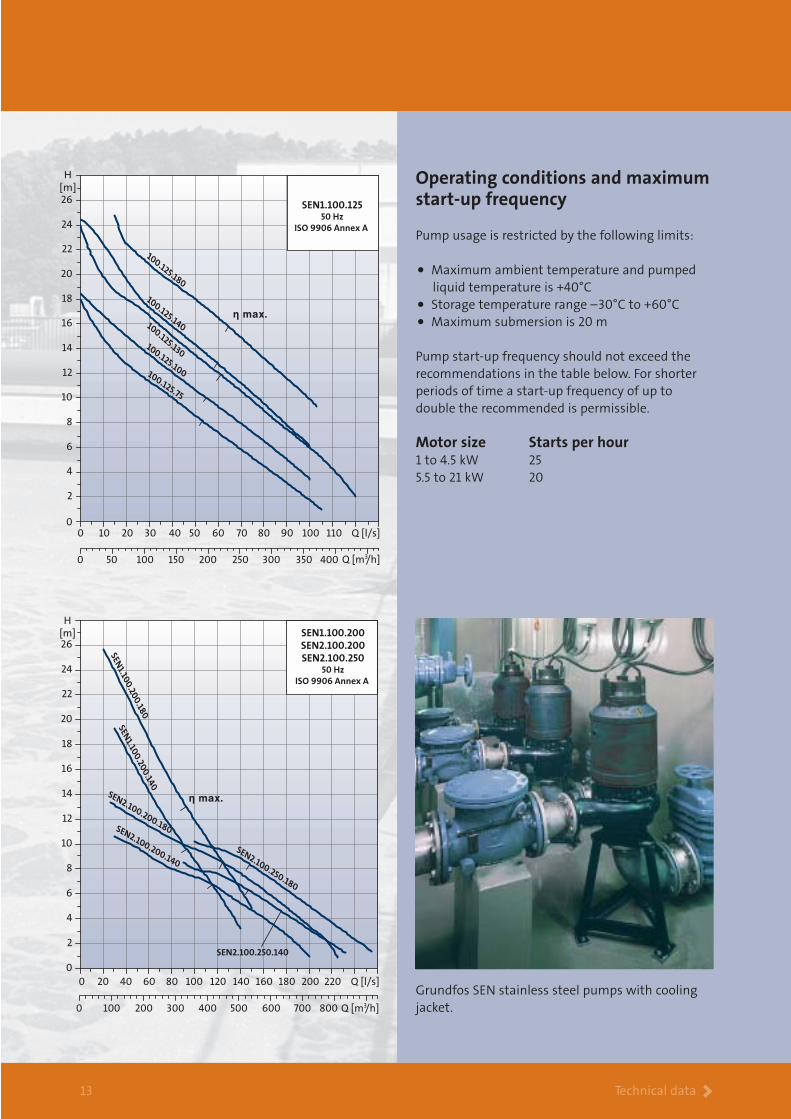
Operating conditions and maximumstart-up frequency
Pump usage is restricted by the following limits:
• Maximum ambient temperature and pumped
liquid temperature is +40°C
• Storage temperature range –30°C to +60°C
• Maximum submersion is 20 m
Pump start-up frequency should not exceed the
recommendations in the table below. For shorter
periods of time a start-up frequency of up to
double the recommended is permissible.
Motor size Starts per hour1 to 4.5 kW 25
5.5 to 21 kW 20
0 10 20 30 40 50 60 70 80 90 100 110 Q [l/s]0
2
4
6
8
10
12
14
16
18
20
22
24
26
0 50 100 150 200 250 300 350 400 Q [m3/h]
100.125.180
100.125.140100.125.130100.125.100100.125.75
H
[m]
SEN1.100.12550 Hz
ISO 9906 Annex A
0 20 40 60 80 100 120 140 160 180 200 220 Q [l/s]
0
2
4
6
8
10
12
14
16
18
20
22
24
26
H
[m]
0 100 200 300 400 500 600 700 800
SEN2.100.250.180
SEN2.100.200.180
SEN1.10
0.20
0.18
0
SEN2.100.250.140
SEN2.100.200.140
SEN1.10
0.20
0.14
0SEN1.100.200
SEN2.100.200
SEN2.100.25050 Hz
ISO 9906 Annex A
Q [m3/h]
Grundfos SEN stainless steel pumps with cooling
jacket.
η max.
η max.

14
Electrical data and pump designation
Technical data >
Pump type Starting methodMax. solids size[mm]
Weight[kg]
I sI 1/1
I 1/1
[A]n
[min -1]P2
[kW]
SENV.80.80.74 (Ex) 80 7.4 2960 Star/delta 16.6 12.3 180
SENV.80.80.94 (Ex) 80 9.4 2940 Star/delta 19.4 10.4 170
SENV 80.80.120 (Ex) 80 12.0 2910 Star/delta 23.6 7.6 200
SENV 80.80.150 (Ex) 80 15.0 2780 Star/delta 41.2 9.1 250
SENV.80.80.210 (Ex) 80 21.0 2780 Star/delta 41.2 6.6 250
SENV 80.100.10 (Ex) 80 1.0 1440 Direct-on-line 4.3 6.9 60
SENV.80.100.13 (Ex) 80 1.3 1440 Direct-on-line 4.3 6.9 60
SENV 80.100.16 (Ex) 80 1.6 1440 Direct-on-line 4.3 6.9 60
SENV 80.100.23 (Ex) 80 2.3 1400 Direct-on-line 5.4 5.5 60
SENV 80.100.29 (Ex) 80 2.9 1430 Direct-on-line 8.1 6.2 100
SENV 80.100.42 (Ex) 80 4.2 1390 Direct-on-line 10.4 5.0 100
SENV 80.100.45 (Ex) 80 4.5 2840 Direct-on-line 10.2 7.0 100
SENV.100.100.29 (Ex) 100 2.9 1430 Direct-on-line 8.1 6.2 100
SENV.100.100.42 (Ex) 100 4.2 1380 Direct-on-line 10.4 5.0 100
SEN1.80.100.55 (Ex) 80 5.5 1460 Star/delta 13.8 7.4 210
SEN1.80.100.75 (Ex) 80 7.5 1440 Star/delta 16.7 7.4 210
SEN1.80.100.100 (Ex) 80 10.0 1460 Star/delta 22.0 9.6 240
SEN1.80.100.130 (Ex) 80 13.0 1440 Star/delta 26.4 8.3 240
SEN1.80.100.140 (Ex) 80 14.0 1470 Star/delta 33.9 4.9 285
SEN1.80.100.180 (Ex) 80 18.0 1460 Star/delta 37.4 4.4 310
SEN1.80.200.75 (Ex) 80 7.5 1440 Star/delta 16.7 7.4 320
SEN1.80.200.100 (Ex) 80 10.0 1460 Star/delta 22.0 9.6 415
SEN1.80.200.130 (Ex) 80 13.0 1440 Star/delta 26.4 8.3 415
SEN1.100.100.17 100 1.7 910 Direct-on-line 5.5 6.0 110
SEN1.100.100.20 (Ex) 100 2.0 1430 Direct-on-line 8.1 6.2 110
SEN1.100.100.29 (Ex) 100 2.9 1430 Direct-on-line 8.1 6.2 110
SEN1.100.100.42 (Ex) 100 4.2 1390 Direct-on-line 10.5 5.0 110
SEN1.100.100.55 (Ex) 100 5.5 1460 Star/delta 13.8 7.4 205
SEN1.100.100.75 (Ex) 100 7.5 1440 Star/delta 16.7 7.4 200
SEN1.100.100.100 (Ex) 100 10.0 1460 Star/delta 22.0 9.6 215
SEN1.100.100.130 (Ex) 100 13.0 1440 Star/delta 26.4 8.3 215
SEN1.100.125.75 (Ex) 100 7.5 1440 Star/delta 16.7 7.4 235
SEN1.100.125.100 (Ex) 100 10.0 1460 Star/delta 22.0 9.6 235
SEN1.100.125.130 (Ex) 100 13.0 1440 Star/delta 26.4 8.3 235
SEN1.100.125.140 (Ex) 100 14.0 1450 Star/delta 33.9 4.9 320
SEN1.100.125.180 (Ex) 100 18.0 1460 Star/delta 37.4 4.4 310
SEN1.100.200.140 (Ex) 100 14.0 1470 Star/delta 33.9 8.3 390
SEN2.100.200.140 (Ex) 100 14.0 1470 Star/delta 33.9 8.3 400
SEN1.100.200.180 (Ex) 100 18.0 1460 Star/delta 37.4 4.4 390
SEN2.100.200.180 (Ex) 100 18.0 1460 Star/delta 37.4 4.4 405
SEN2.100.250.140 (Ex) 100 14.0 1470 Star/delta 33.9 8.3 470
SEN2.100.250.180 (Ex) 100 18.0 1460 Star/delta 37.4 4.4 545

Technical data >15
Dimensions [mm]
DN1 A1 B1 C1 D1 E1 F1 G1 H1 K1 L1 M1 N1 O1 ØP1 ØR1 ØS1 ØT1 U1 V1 X1 Y1 ØZ1Pump type
SENV.80.80.74 100 965 865 100 705 465 180 370 190 120 260 180
SENV.80.80.94 100 965 805 100 705 465 180 370 190 120 260 180
SENV.80.80.120 100 965 805 100 705 465 180 370 190 120 260 180
SENV 80.80.150 80 1055 945 110 610 370 180 395 215 180 260 325
SENV.80.80.210 80 1055 945 110 610 370 180 395 215 180 260 325
SENV 80.100.10 100 835 650 185 445 270 130 255 130 120 260 180
SENV.80.100.13 100 835 650 185 445 270 130 255 130 120 260 180
SENV 80.100.16 100 835 650 185 445 270 130 255 130 99 160 184
SENV 80.100.23 100 835 650 185 445 270 130 255 130 120 260 180
SENV 80.100.29 100 735 655 80 475 270 155 310 155 99 160 184
SENV 80.100.42 100 735 655 80 475 270 155 310 155 99 160 184
SENV 80.100.45 100 835 655 180 520 310 150 300 150 120 260 180
SENV.100.100.29 100 830 690 140 540 330 155 320 155 120 260 180
SENV.100.100.42 100 830 690 140 540 330 155 320 155 120 260 180
SEN1.80.100.55 100 1000 900 100 585 350 180 375 190 120 260 180
SEN1.80.100.75 100 1000 900 100 585 350 180 375 190 120 260 180
SEN1.80.100.100 100 1000 900 100 585 350 180 375 190 120 260 180
SEN1.80.100.130 100 1000 900 100 585 350 180 375 190 120 260 180
SEN1.80.100.140 100 1050 960 90 670 390 215 440 210 200 260 325
SEN1.80.100.180 100 1050 960 90 670 390 215 440 210 200 260 325
SEN1.80.200.75 200 1130 990 140 950 550 325 625 260 300 400 540
SEN1.80.200.100 200 1130 990 140 950 550 325 625 260 300 400 540
SEN1.80.200.130 200 1130 990 140 950 550 325 625 260 300 400 540
SEN1.100.100.17 100 810 710 100 545 320 165 335 160 120 260 180
SEN1.100.100.20 100 810 710 100 545 320 165 335 160 120 260 180
SEN1.100.100.29 100 810 710 100 545 320 165 335 160 120 260 180
SEN1.100.100.42 100 810 710 100 545 320 165 335 160 120 260 180
SEN1.100.100.55 100 1035 935 100 610 375 180 380 190 120 260 180
SEN1.100.100.75 100 1035 935 100 610 375 180 380 190 120 260 180
SEN1.100.100.100 100 1035 935 100 610 375 180 380 190 120 260 180
SEN1.100.100.130 100 1035 935 100 610 375 180 380 190 120 260 180
SEN1.100.125.75 150 1130 925 205 735 455 210 435 190 250 380 280
SEN1.100.125.100 150 1130 925 205 735 455 210 435 190 250 380 280
SEN1.100.125.130 150 1130 925 205 735 455 210 435 190 250 380 280
SEN1.100.125.140 150 1185 1000 185 720 432 215 445 210 250 380 280
SEN1.100.125.180 150 1185 1000 185 720 432 215 445 210 250 380 280
SEN1.100.200.140 200 1215 1020 195 930 590 265 550 235 300 400 540
SEN2.100.200.140 200 1215 1020 195 930 590 265 550 235 300 400 540
SEN1.100.200.180 200 1215 1020 195 930 590 265 550 235 300 400 540
SEN2.100.200.180 200 1215 1020 195 930 590 265 550 235 300 400 540
SEN2.100.250.140 250 1205 1060 145 1290 840 370 730 310 350 400 620
SEN2.100.250.180 250 1205 1060 145 1290 840 370 730 310 350 400 620
220 60 180 220 18 20 205 180 121 180 48
220 60 180 220 18 20 205 180 121 180 48
220 60 180 220 18 20 205 180 121 180 48
375 75 160 200 18 24 230 203 80 80 60
375 75 160 200 18 24 230 203 80 80 60
220 60 180 220 18 20 205 180 121 180 48
220 60 180 220 18 20 205 180 121 180 48
206 60 180 220 18 20 123 167 65 80 48
220 60 180 220 18 20 205 180 121 180 48
206 60 180 220 18 20 123 167 65 80 48
206 60 180 220 18 20 123 167 65 80 48
220 60 180 220 18 20 205 180 121 180 48
220 60 180 220 18 20 205 180 121 180 48
220 60 180 220 18 20 205 180 121 180 48
220 60 180 220 18 20 205 180 121 180 48
220 60 180 220 18 20 205 180 121 180 48
220 60 180 220 18 20 205 180 121 180 48
220 60 180 220 18 20 205 180 121 180 48
375 75 180 220 18 24 230 223 80 80 60
375 75 180 220 18 24 230 223 80 80 60
600 150 295 340 22 28 460 320 70 20 88
600 150 295 340 22 28 460 320 70 20 88
600 150 295 340 22 28 460 320 70 20 88
220 60 180 220 18 20 205 180 121 180 48
220 60 180 220 18 20 205 180 121 180 48
220 60 180 220 18 20 205 180 121 180 48
220 60 180 220 18 20 205 180 121 180 48
220 60 180 220 18 20 205 180 121 180 48
220 60 180 220 18 20 205 180 121 180 48
220 60 180 220 18 20 205 180 121 180 48
220 60 180 220 18 20 205 180 121 180 48
500 100 240 285 22 24 320 265 115 165 77
500 100 240 285 22 24 320 265 115 165 77
500 100 240 285 22 24 320 265 115 165 77
500 100 240 285 22 24 320 265 115 165 77
500 100 240 285 22 24 320 265 115 165 77
600 150 295 340 22 28 460 320 70 20 88
600 150 295 340 22 28 460 320 70 20 88
600 150 295 340 22 28 460 320 70 20 88
600 150 295 340 22 28 460 320 70 20 88
700 150 350 395 23 28 500 370 205 270 88
700 150 350 395 23 28 500 370 205 270 88
Submerged installation on auto-coupling
Dimensions and installation

Technical data >16
Dimensions and installation
Vertical dry installation
Dimensions [mm]
DN1 DN2 A B C D E F G H ØJ ØK ØL ØM ØN
SENV.80.80.94 100 80 1325 620 425 580 400 370 270 30° M16 180 200 160 24
SENV 80.80.120 100 80 1325 620 425 580 400 370 270 30° M16 180 200 160 24
SENV 80.100.10 100 100 1120 545 425 347 217 255 270 30° M16 180 225 180 24
SENV.80.100.13 100 100 1120 545 425 347 217 255 270 30° M16 180 225 180 24
SENV 80.100.16 100 100 1120 545 425 347 217 255 270 30° M16 180 225 180 24
SENV 80.100.29 100 100 1095 525 425 372 217 320 270 30° M16 180 225 180 24
SENV.100.100.29 100 100 1135 565 425 420 265 320 270 30° M16 180 225 180 24
SEN1.80.100.55 100 100 1365 625 425 465 285 375 270 30° M16 180 200 160 24
SEN1.80.100.75 100 100 1365 625 425 465 285 375 270 30° M16 180 200 160 24
SEN1.80.100.100 100 100 1365 625 425 465 285 375 270 30° M16 180 225 180 24
SEN1.80.100.130 100 100 1365 625 425 465 285 375 270 30° M16 180 225 180 24
SEN1.80.100.140 150 100 1605 815 600 570 355 435 300 30° M20 240 220 180 24
SEN1.80.100.180 150 100 1605 815 600 570 355 435 300 30° M20 240 220 180 24
SEN1.80.200.75 200 200 1700 970 700 785 460 625 350 30° M20 295 340 295 24
SEN1.80.200.100 200 200 1700 970 700 785 460 625 350 30° M20 295 340 295 24
SEN1.80.200.130 200 200 1700 970 700 785 460 625 350 30° M20 295 340 295 24
SEN1.100.100.17 100 100 1150 600 425 425 257 335 270 30° M16 180 220 180 24
SEN1.100.100.20 100 100 1150 600 425 425 257 335 270 30° M16 180 220 180 24
SEN1.100.100.29 100 100 1150 600 425 425 257 335 270 30° M16 180 220 180 24
SEN1.100.100.55 150 100 1575 805 600 492 312 380 300 30° M20 240 225 180 24
SEN1.100.100.75 150 100 1575 805 600 492 312 380 300 30° M20 240 225 180 24
SEN1.100.100.100 150 100 1575 805 600 492 312 380 300 30° M20 240 225 180 24
SEN1.100.100.130 150 100 1575 805 600 492 312 380 300 30° M20 240 225 180 24
SEN1.100.130.75 150 130 1565 815 600 590 380 435 300 30° M20 240 250 210 24
SEN1.100.130.100 150 130 1565 815 600 590 380 435 300 30° M20 240 250 210 24
SEN1.100.130.130 150 130 1570 815 600 590 380 435 300 30° M20 240 250 210 24
SEN1.100.125.140 150 125 1640 840 600 575 360 445 300 30° M20 240 250 210 24
SEN1.100.125.180 150 125 1640 840 600 575 360 445 300 30° M20 240 250 210 24
SEN1.100.200.140 200 200 1730 920 700 765 500 550 350 30° M20 295 340 295 24
SEN2.100.200.140 200 200 1730 920 700 765 500 550 350 30° M20 295 340 295 24
SEN1.100.200.180 200 200 1730 920 700 765 500 550 350 30° M20 295 340 295 24
SEN2.100.200.180 200 200 1730 920 700 765 500 550 350 30° M20 295 340 295 24
SEN2.100.250.140 250 250 1910 1105 825 1120 750 730 400 30° M20 350 406 350 28
SEN2.100.250.180 250 250 1910 1105 825 1120 750 730 400 30° M20 350 406 350 28
Pump typeØP
19
19
19
19
19
19
19
19
19
19
19
19
19
24
24
24
19
19
19
19
19
19
19
19
19
19
19
19
24
24
24
24
24
24
17 Technical data >
Horizontal dry installation
Dimensions [mm]
DN1 DN2 A B D E F G H ØL M O P Q R
SENV.80.80.94 100 80 895 820 700 400 370 180 195 18 500 115 300 390 450
SENV 80.80.120 100 80 895 820 700 400 370 180 195 18 500 115 300 390 450
SENV 80.100.10 100 100 705 250 417 217 275 150 118 20 – 130 200 190 250
SENV.80.100.13 100 100 705 250 417 217 275 150 118 20 – 130 200 190 250
SENV 80.100.16 100 100 705 250 417 217 275 150 118 20 – 130 200 190 250
SENV 80.100.29 100 100 675 250 437 217 320 160 102 20 150 57 220 230 300
SENV.100.100.29 100 100 715 250 485 265 320 165 142 20 150 57 220 230 300
SEN1.80.100.55 100 100 935 820 585 285 375 190 195 20 500 115 300 390 450
SEN1.80.100.75 100 100 935 820 585 285 375 190 195 20 500 115 300 390 450
SEN1.80.100.100 100 100 935 820 585 285 375 190 195 20 500 115 300 390 450
SEN1.80.100.130 100 100 935 820 585 285 375 190 195 20 500 115 300 390 450
SEN1.80.100.140 150 100 1020 820 655 355 440 230 185 20 500 115 375 390 450
SEN1.80.100.180 150 100 1020 820 655 355 440 230 185 20 500 115 375 390 450
SEN1.80.200.75 200 200 1000 820 860 460 625 365 275 18 500 115 400 390 450
SEN1.80.200.100 200 200 1000 820 860 460 625 365 275 18 500 115 400 390 450
SEN1.80.200.130 200 200 1000 820 860 460 625 365 275 18 500 115 400 390 450
SEN1.100.100.17 100 100 735 250 477 257 335 175 180 20 150 57 220 230 335
SEN1.100.100.20 100 100 735 250 477 257 335 175 180 20 150 57 220 230 335
SEN1.100.100.29 100 100 735 250 477 257 335 175 180 20 150 57 220 230 335
SEN1.100.100.55 150 100 960 820 610 310 380 190 190 20 500 130 300 390 450
SEN1.100.100.75 150 100 960 820 610 310 380 190 190 20 500 130 300 390 450
SEN1.100.100.100 150 100 960 820 610 310 380 190 190 20 500 130 300 390 450
SEN1.100.100.130 150 100 960 820 612 312 380 190 175 20 500 130 300 390 450
SEN1.100.130.75 150 130 950 820 680 380 430 240 200 20 500 130 300 390 450
SEN1.100.130.100 150 130 950 820 680 380 430 240 200 20 500 130 300 390 450
SEN1.100.130.130 150 130 950 820 680 380 430 240 200 20 500 130 300 390 450
SEN1.100.125.140 150 125 1035 820 735 360 555 345 210 20 500 100 375 390 450
SEN1.100.125.180 150 125 1035 820 735 360 555 345 210 20 500 100 375 390 450
SEN1.100.200.140 200 200 1045 820 875 500 550 315 220 20 500 115 375 390 450
SEN2.100.200.140 200 200 1045 820 875 500 550 315 220 20 500 115 375 390 450
SEN1.100.200.180 200 200 1045 820 875 500 550 315 220 20 500 115 375 390 450
SEN2.100.200.180 200 200 1045 820 875 500 550 315 220 20 500 115 375 390 450
SEN2.100.250.140 250 250 1070 1250 750 730 420 265 18 500 115 500 390 450
SEN2.100.250.180 250 250 1070 1250 750 730 420 265 18 500 115 500 390 450
Pump type

Dimensions [mm]
DN A B С D E F G H
SENV.80.80.74 100 930 350 555 180 180 370 460 290
SENV.80.80.94 100 930 350 555 180 180 370 460 290
SENV 80.80.120 100 930 350 555 180 180 370 460 290
SENV 80.80.150 80 1080 350 635 180 215 395 430 280
SENV.80.80.210 80 1080 350 635 180 215 395 430 280
SENV 80.100.10 80 735 305 490 150 125 275 305 160
SENV.80.100.13 80 735 305 490 150 125 275 305 160
SENV 80.100.16 80 735 305 490 150 125 275 305 160
SENV 80.100.23 80 735 305 490 150 125 275 305 160
SENV 80.100.29 80 765 305 490 155 155 310 355 195
SENV 80.100.42 80 765 305 490 155 155 310 355 195
SENV 80.100.45 100 725 305 545 150 150 300 335 190
SENV.100.100.29 100 805 305 565 165 155 320 380 230
SENV.100.100.42 100 805 305 565 165 155 320 380 230
SEN1.80.100.55 100 1035 350 610 185 190 375 435 290
SEN1.80.100.75 100 1035 350 610 185 190 375 435 290
SEN1.80.100.100 100 1035 350 610 185 190 375 435 290
SEN1.80.100.130 100 1035 350 610 185 190 375 435 290
SEN1.80.100.140 100 1070 550 775 230 210 550 550 280
SEN1.80.100.180 100 1070 550 775 230 210 550 550 280
SEN1.80.200.75 200 1110 550 1210 365 275 640 815 380
SEN1.80.200.100 200 1110 550 1210 365 275 640 815 380
SEN1.80.200.130 200 1110 550 1210 365 275 640 815 380
SEN1.100.100.17
SEN1.100.100.20 100 820 305 570 175 160 335 415 270
SEN1.100.100.29 100 820 305 570 175 160 335 415 270
SEN1.100.100.42 100 820 305 570 175 160 335 415 270
SEN1.100.100.55 100 1075 350 640 190 190 380 450 300
SEN1.100.100.75 100 1075 350 640 190 190 380 450 300
SEN1.100.100.100 100 1075 350 640 190 190 380 450 300
SEN1.100.100.130 100 1075 350 640 190 190 380 450 300
SEN1.100.130.75 150 1060 350 870 240 190 430 590 310
SEN1.100.130.100 150 1060 350 870 240 190 430 590 310
SEN1.100.130.130 150 1060 350 870 240 190 430 590 310
SEN1.100.125.140 150 1105 550 915 235 210 550 585 305
SEN1.100.125.180 150 1105 550 915 235 210 550 585 305
SEN1.100.200.140 200 1125 550 1200 315 235 590 750 315
SEN2.100.200.140 200 1125 550 1200 315 235 590 750 315
SEN1.100.200.180 200 1125 550 1200 315 235 590 750 315
SEN2.100.200.180 200 1125 550 1200 315 235 590 750 315
SEN2.100.250.140
SEN2.100.250.180
Pump type
Technical data >18
Dimensions and installation
Submerged free-standing installation
Pumped liquidsThe Grundfos SEN stainless steel wastewater
pumps are suitable for pumping:
• Sewage and wastewater containing long fibres
and solids up to 80 mm or 100 mm.
• Industrial effluent containing abrasives or sticky
material.
• Aggressive or corrosive drainwater and effluent
• Sludge and drainwater from aggressive or corro-
sive environments.
Liquid temperature: 0°C to +40°C.
Max. density: 1000 kg/m3.
Motor2, 4 and 6-pole motors for 50 Hz with voltage toler-
ance of ± 10%. All motors have a built-in protection
device consisting of three thermal switches embed-
ded in the stator windings and a mechanically acti-
vated moisture-sensing micro switch below the
motor top cover.
Voltage toleranges: 2.9 kW - 4.5 kW + 5% - 15%
Other motors + 10% - 10%
50Hz motors with windings for other voltages
available on request, including the entire pump
range wound for 60 Hz.
Enclosure class: IP 68.
Insulation Class: F (155°C).

Technical data >19
Material specifications
Stator housing Cast stainless steel 1.4408 CF-8M
Pump housing Cast stainless steel 1.4408 CF-8M
Guide claw (for pumps
installed on auto-coupling only)
Impeller Cast stainless steel 1.4408 CF-8M
Pump shaft Stainless steel 1.4460 329
Bolts and nuts Stainless steel 1.4436 316
Cooling jacket (5.5-21.0 kW) Cast stainless steel 1.4408 CF-8M
O-rings NBR
O-rings, mechanical shaft seal FKM
Bearings Heavy-duty prelubricated ball bearings
Primary shaft seal SiC/SiC
Secondary shaft seal SiC/carbon
Lifting bracket (1.0-4.5 kW) Stainless steel 1.4436 316
Lifting bracket (5.5-21.0 kW) Stainless steel 1.4436 316
Cables EPDM
Cable entry Cast stainless steel 1.4408 CF-8M
Surface protection 150 my two-component epoxy coating
Oil SAE 10 W 30
Part Material DIN / EN AISI
Cast stainless steel 1.4408 CF-8M
Stator housing Cast iron EN-JL1040
Pump housing Cast stainless steel 1.4408 CF-8M
Guide claw (for pumps
installed on auto-coupling only)
Impeller Cast stainless steel 1.4408 CF-8M
Pump shaft Stainless steel 1.4460 329
Bolts and nuts Stainless steel 1.4436 316
Cooling jacket (5.5-21.0 kW) Ductile iron EN-JS1050
O-rings NBR
O-rings, mechanical shaft seal FKM
Bearings Heavy-duty prelubricated ball bearings
Primary shaft seal SiC/SiC
Secondary shaft seal SiC/carbon
Lifting bracket (1.0-4.5 kW) Stainless steel 1.4436 316
Lifting bracket (5.5-21.0 kW) Ductile iron EN-JS1050
Cables EPDM
Cable entry PA
Surface protection 150 my two-component epoxy coating
Oil SAE 10 W 30
Part Material DIN / EN AISI
Cast stainless steel 1.4408 CF-8M
Stator housing Cast iron EN-JL1040
Pump housing Cast iron EN-JL1040
Guide claw (for pumps
installed on auto-coupling only)
Impeller Cast stainless steel 1.4408 CF-8M
Pump shaft Stainless steel 1.4460 329
Bolts and nuts Stainless steel 1.4436 316
Cooling jacket (5.5-21.0 kW) Ductile iron EN-JS1050
O-rings NBR
O-rings, mechanical shaft seal FKM
Bearings Heavy-duty prelubricated ball bearings
Primary shaft seal SiC/SiC
Secondary shaft seal SiC/carbon
Lifting bracket (1.0-4.5 kW) Stainless steel 1.4436 316
Lifting bracket (5.5-21.0 kW) Ductile iron EN-JS1050
Cables EPDM
Cable entry PA
Surface protection 150 my two-component epoxy coating
Oil SAE 10 W 30
Part Material DIN / EN AISI
Cast iron EN-JL1040
Entirely stainless steel Version R
Stainless steel impellerVersion Q
Hydraulic parts of stainless steelVersion S

Technical data >20
Pump types and product numbers
Pump type Submerged version Dry version
SENV.80.80.74 96089703 96089705 96089707
SENV.80.80.94 96089715 96089717 96089719
SENV.80.80.120 96089727 96089729 96089731 96089728 96089730 96089732
SENV.80.80.150 96089739 96089740 96089741
SENV.80.80.210 96089745 96089746 96089747
SENV.80.100.10 96089661 96089663 96089661 96089663
SENV.80.100.13 96089667 96089669 96089667 96089669
SENV.80.100.16 96089673 96089675 96089673 96089675
SENV.80.100.23 96089679 96089681
SENV.80.100.29 96089685 96089686 96089687 96089685 96089686 96089687
SENV.80.100.42 96089691 96089692 96089693
SENV.80.100.45 96089697 96089698 96089699
SENV.100.100.29 96089751 96089753 96089755 96089751 96089753 96089755
SENV.100.100.42 96089763 96089764 96089765
SEN1.80.100.55 96089769 96089771 96089773 96089770 96089772 96089774
SEN1.80.100.75 96089781 96089783 96089785 96089782 96089784 96089786
SEN1.80.100.100 96089805 96089807 96089809 96089806 96089808 96089810
SEN1.80.100.130 96089829 96089831 96089833 96089830 96089832 96089834
SEN1.80.100.140 96089853 96089855 96089857 96089854 96089856 96089858
SEN1.80.100.180 96089865 96089867 96089869 96089866 96089868 96089870
SEN1.80.200.75 96089793 96089795 96089797 96089794 96089796 96089798
SEN1.80.200.100 96089817 96089819 96089821 96089818 96089820 96089822
SEN1.80.200.130 96089841 96089843 96089845 96089842 96089844 96089846
SEN1.100.100.17 96089877 96089879 96089881 96089877 96089879 96089881
SEN1.100.100.20 96089889 96089891 96089893 96089889 96089891 96089893
SEN1.100.100.29 96089901 96089903 96089905 96089901 96089903 96089905
SEN1.100.100.42 96089913 96089914 96089915 96089913 96089914 96089915
SEN1.100.100.55 96089919 96089921 96089923 96089920 96089922 96089924
SEN1.100.100.75 96089931 96089933 96089935 96089932 96089934 96089936
SEN1.100.100.100 96089955 96089957 96089959 96089956 96089958 96089960
SEN1.100.100.130 96089979 96089981 96089983 96089980 96089982 96089984
SEN1.100.125.75 96089943 96089945 96089947 96089944 96089946 96089948
SEN1.100.125.100 96089967 96089969 96089971 96089968 96089970 96089972
SEN1.100.125.130 96089991 96089993 96089995 96089992 96089994 96089996
SEN1.100.125.140 96090003 96090005 96090007 96090004 96090006 96090008
SEN1.100.125.180 96090051 96090053 96090055 96090052 96090054 96090056
SEN1.100.200.140 96090015 96090017 96090019 96090016 96090018 96090020
SEN2.100.200.140 96090027 96090029 96090031 96090028 96090030 96090032
SEN1.100.200.180 96090063 96090065 96090067 96090064 96090066 96090068
SEN2.100.200.180 96090075 96090077 96090079 96090076 96090078 96090080
SEN2.100.250.140 96090039 96090041 96090043 96090040 96090042 96090044
SEN2.100.250.180 96090087 96090089 96090091 96090088 96090090 96090092
Some pump models are suitable for submerged as well as dry installation (e.g. SENV.80.100.10).
These pump models will appear with identical product number in the table.
All pump types are available in explosion-proof version.
Product number
Q RS Q S R
The Grundfos SEN range of stainless steel pumps
comprises models with standard motors as well as
explosion-proof motors for mains supply of 3 x 400 V,
50 Hz.
All SEN pump models have a built-in thermal switch
and a moisture sensor. The pumps are supplied with
8 m cable with protection sleeve on the free cable
end. The pumps must be connected to a separate
motor starter.

Accessories > 21
Accessories
Stainlesssteel
Cast iron/steel
Pump outlet
DN 80 for 7.4-12.0 kW • 96090109 96094504
DN 80 for 15.0-21.0 kW • 96090122 96094508
DN 100 for 1.0-4.5 kW • • 96090104 96094503
DN 100 for 5.5-13.0 kW • • 96090111 96094505
DN 100 for 14.0-18.0 kW • 96090124 96094509
DN 125 for 7.5-18.0 kW • 96090114 96094506
DN 200 for 7.5-18.0 kW • • 96090118 96094507
DN 250 for 14.0-18.0 kW • 96090131 96094510
Hose connection
80 mm for 15.0-21.0 kW • 96090106 96094511
100 mm for 1.0-4.5 kW • • 96090112 96094512
100 mm for 5.5-13.0 kW • • 96090116 96094513
100 mm for 14.0-18.0 kW • 96090120 96094514
150 mm for 7.5 - 13.0 kW • 96090123 96094515
150 mm for 14.0 - 18.0 kW • 96090126 96094516
200 mm for 7.5 - 13.0 kW • 96090128 96094517
200 mm for 14.0 - 18.0 kW • 96090130 96094518
Pump outlet
DN 80/100 •(1) •(2) 96090101 96094519
DN 100 for 1.7-2.9 kW •(3) • 96090105 96094520
DN 100 for 5.5-13.0 kW • • 96090110 96094521
DN 125 for 7.5-14.0 kW • 96090115 96094522
DN 200 for 7.5-18.0 kW • • 96090119 96094523
DN 100/125 for 14.0 -18.0 kW • •(4) 96090125 96094524
DN 250 14.0 -18.0 kW • 96090132 96094525
Pump outlet
DN 100 for 1.0-1.6 kW • 96090135 96094526
DN 100 for 1.7-2.9 kW • • 96090133 96094527
DN 200 for 7.5-13.0 kW • 96090134 96094528
DN 100 for 5.5-13.0 kW • • 96090136 96094529
DN 100/125 for 5.5-13.0 kW • • 96090137 96094530
DN 200 for 14.0-18.0 kW • 96090138 96094531
DN 250 for 14.0-18.0 kW • 96090139 96094532
DN 100/125 for 14.0-18.0 kW • • 96090140 96094533
Flange connection
DN 80/80 96480844 96060928
DN 100/100 96480845 96060930
DN 150/150 96480846 96060934
DN 200/200 96480847 96060938
DN 250/250 96480848 96060942
Length of chain
4 m 96094534 96468283
6 m 96068195 96468285
8 m 96094535 96468286
62500020
Outdoor installation 62500021
Indoor installation 62500022
Auto-coupling.
Incl. guide claw, profile seal,
guide rail bracket and screws.
For submerged installation.
See page 15 for auto-coupling
outlet dimensions (DN).
Description Material
Productnumber
80.8
0
80.1
00
80.2
00
100.
100
100.
125
100.
200
100.
250
Pump type
Ring stand.
Incl. 90° bend for hose con-
nection, screws and gaskets.
For submerged installation,
portable.
Base stand.
Incl. screws and gaskets.
Not including 90°
suction bend.
For vertical dry installation.
Base stand.
Incl. screws and bracket.
For horizontal
dry installation.
90° suction bend with flanges.
For vertical dry installation.
Lifting chain with shackle.
Max. load 1100 kg.
Signal lamp.
Outdoor installation
1 x 230 V
Acoustic signal (horn).
1 x 230 V
(1): 9.4 - 12.0 kW, (2): 1.0 - 1.6 kW, (3): 2.9 kW only, (4): 18.0 kW

Accessories >22
Level switches and controllers
Float switch, non-mercury. 1 switch with 10 m cable 96 00 33 32
Float switch with 20 m cable 96 00 36 95
Float switch for explosion protection with 10 m cable 96 00 34 21
Float switch for explosion protection with 20 m cable 96 00 35 36
Bracket for level switch 96 00 33 38
1 pump without alarm (2 switches) 62 50 00 13
Standard float switch, non-mercury type, 1 pump with alarm (3 switches) 62 50 00 14
with 10 m cable and bracket 2 pumps without alarm (3 switches) 62 50 00 14
2 pumps with alarm (4 switches) 62 50 00 15
1 pump without alarm (2 switches) 62 50 00 16
Float switches for areas with a risk of explosion , 1 pump with alarm (3 switches) 62 50 00 17
with 10 m cable and bracket 2 pumps without alarm (3 switches) 62 50 00 17
2 pumps with alarm (4 switches) 62 50 00 18
ProductnumberDescription
In addition to the chemical and thermal properties of the water-proof polypropylene housing as well as the polyurethane cable,
the level switches are resistant to alcohol, uric acid, sewage, oils, fats, petrol, fruit acid, as well as a range of chemicals.
Level switch
LC 107 controller for
1 pump
3 x 400 V, direct-on-line starting
LCD 107 controller for
2 pumps
3 x 400 V, direct-on-line starting
LC 108 controller for
1 pump
3 x 400 V, direct-on-line starting
LC 108 controller for
1 pump
3 x 400 V, star-delta starting
LCD 108 controller for
2 pumps
3 x 400 V, direct-on-line starting
LCD 108 controller for
2 pumps
3 x 400 V, star-delta starting
Description
Product numberOperating
currentper pump
[A]
Mainsswitch
required[A]
Includinghour counter
Standardcontroller
Includingstart counter
Includingcombined hour and
start counter
1 - 2.9 25 96 00 24 67
1.6 - 5.0 25 96 00 24 68
3.7 - 12.0 25 96 00 24 69
12.0 - 23.0 40 96 00 24 70
1 - 2.9 25 96 00 24 74
1.6 - 5.0 25 96 00 24 75
3.7 - 12.0 25 96 00 24 76
12.0 - 23.0 40 96 00 24 77
1 - 2.9 25 96 43 39 91 96 43 39 92 96 43 39 93 96 43 39 94
1.6 - 5.0 25 96 43 39 95 96 43 39 96 96 43 39 97 96 43 39 98
3.7 - 12.0 25 96 43 39 99 96 43 40 00 96 43 40 01 96 43 40 02
12.0 - 23.0 40 96 43 40 03 96 43 40 04 96 43 40 05 96 43 40 06
6.4 - 20.0 25 96 43 79 28
20.8 - 30.0 40 96 43 79 50
20.8 - 59.0 80 96 43 79 70
24.2 - 72.0 96 43 79 90
1.0 - 2.9 25 96 43 40 39 96 43 40 40 96 43 40 41 96 43 40 42
1.6 - 5.0 25 96 43 40 43 96 43 40 44 96 43 40 45 96 43 40 46
3.7 - 12.0 40 96 43 40 47 96 43 40 48 96 43 40 49 96 43 40 50
12.0 - 23.0 60 96 43 40 51 96 43 40 52 96 43 40 53 96 43 40 54
6.4 - 20.0 25 96 43 80 32
20.8 - 30.0 40 96 43 80 52
20.8 - 59.0 80 96 43 80 72
24.2 - 72.0 96 43 80 92
Level controller
ProductnumberDescription
Battery back-up 96 00 25 20
Hour counter [400 V] 96 00 25 15
Start counter [400 V] 96 00 25 17
Combined hour and start counter [400 V] 96 00 25 19
25 [A] external mains switch for supply cable 96 00 25 11
40 [A] external mains switch for supply cable 96 00 25 12
80 [A] external mains switch for supply cable 96 00 25 13
LC-Ex4 96 44 03 00

The Range >23
The Grundfos Wastewater Range
The sewage grinder pumps range
Brochure covers the new
Grundfos range of sewage grinder
(SEG) pumps for pumping of
wastewater with toilet discharge.
Heavy-duty submersiblesewage pumps
Brochure covers the Grundfos range
of submersible channel impeller
pumps from 1,65 kW up to 21 kW
and SuperVortex pumps up to
29 kW. All designed for handling
unscreened raw sewage.
Heavy-duty submersiblesewage pumpsBrochure covers the Grundfos
range of sewage pumps from 16 kW
up to 155 kW for handling of raw
sewage in heavy-duty applications.
Super heavy-duty submersible sewage andraw water pumpsBrochure covers the Grundfos range
of super heavy-duty channel pumps,
axial flow pumps, and propeller
pumps from 2,8 kW up to 520 kW.
The portable dewatering pumps range
Brochure covers the Grundfos range
of portable dewatering pumps (DW)
from 0.8 kW to 20 kW for pumping
raw water with abrasives.
The KP/AP stainless steel range
Brochure covers a wide range of
high quality stainless steel pumps
for a variety of domestic and
commercial applications.
The lifting stationsBrochure covers Grundfos lifting
stations for individual as well as
multi-user applications.
The range of controlsBrochure covers the Grundfos
range of controls for the waste-
water pumping systems.

Being responsible is our foundation
Thinking ahead makes it possible
Innovation is the essence
www.grundfos.com
Business with an attitude
Knowledge The sharing of knowledge, experience
and expertise across our global network will always
lead our business forward.
Innovation Combining the best technology with
fresh ways of thinking, we will continue to develop
even better pumps, systems, services and standards.
Solution With a complete product range, capable
of providing every conceivable water solution, we are
the most complete player on the market.
96
48
50
51
04
02
VE
NT
UR
EM
AR
KE
TIN
G A
S