stackstone/romanstack installation guide · stackstone ® / romanstack installation guide ©2004...
TRANSCRIPT

The
So
lid C
hoic
e
PisaStone
Pisa2
RomanPisa
StackStone
Split'nStack
RomanStack
SienaStone
VeronaStone
DuraHold
DuraHold2
®
®
PisaStone
Pisa2
RomanPisa
StackStone
Split'nStack
RomanStack
SienaStone
VeronaStone
DuraHold
DuraHold2
®
®
/
Advanced Corner Unit Instructions
Installation Guide
Advanced Corner Unit Instructions
Written & illustrated by: Robert Bowers, p.eng
Eric Jonasson, e.i.t.Claudia Yun Kang, b.eng
Tyler Matys, p.eng
Mark Risi Allison Uher
StackStone® and RomanStack®
Installation Guide

Risi Stone Systems8500 Leslie Street, Suite 390Thornhill, ON L3T 7M8 Canada© 2004 by Risi Stone SystemsAll rights reserved. Published 2004Printed in Canada
Risi Stone Systems has attempted to ensure that all information contained in this guide is correct. However, there is the possibility that this guide may contain errors. Review all designs with your local sales representative prior to construction. Final determination of the suitability of any information or material is the sole responsibility of the user.
Toll-free: 1-800-626-WALL (9255)Fax: 905-882-4556Email: [email protected]: www.risistone.com
introduction
The StackStone® and RomanStack® System ..................................1
Block Details ..............................................................................2
installation .....................................................................................3
basic details
Straight Walls.............................................................................6
Corners .....................................................................................7
Curves ....................................................................................10
specific applications
Pillars ......................................................................................14
Tree Rings ...............................................................................16
Other Applications ...................................................................17
specifications................................................................................18
glossary........................................................................................21
contents
StackStone® / RomanStack® Installation Guide ©2004 Risi Stone Systems
introd
uction
the StackStone® and RomanStack® system
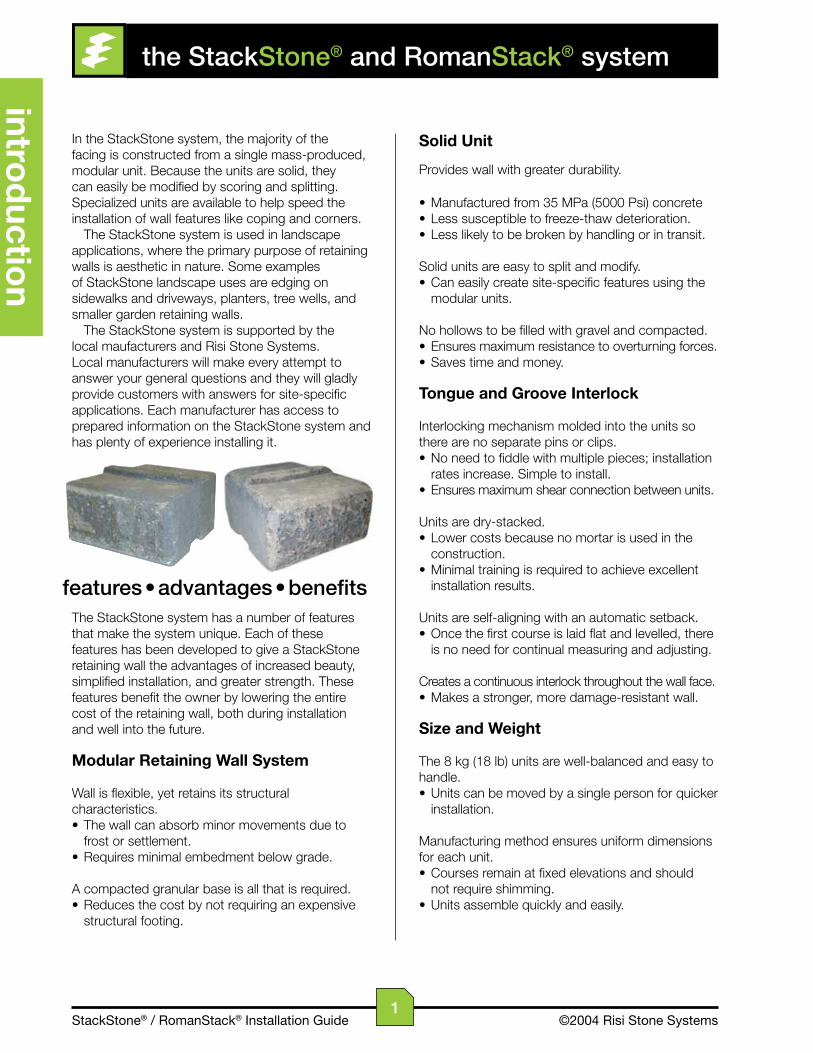
In the StackStone system, the majority of the facing is constructed from a single mass-produced, modular unit. Because the units are solid, they can easily be modified by scoring and splitting. Specialized units are available to help speed the installation of wall features like coping and corners.
The StackStone system is used in landscape applications, where the primary purpose of retaining walls is aesthetic in nature. Some examples of StackStone landscape uses are edging on sidewalks and driveways, planters, tree wells, and smaller garden retaining walls.
The StackStone system is supported by the local maufacturers and Risi Stone Systems. Local manufacturers will make every attempt to answer your general questions and they will gladly provide customers with answers for site-specific applications. Each manufacturer has access to prepared information on the StackStone system and has plenty of experience installing it.
features • advantages • benefitsThe StackStone system has a number of features that make the system unique. Each of these features has been developed to give a StackStone retaining wall the advantages of increased beauty, simplified installation, and greater strength. These features benefit the owner by lowering the entire cost of the retaining wall, both during installation and well into the future.
Modular Retaining Wall System
Wall is flexible, yet retains its structural characteristics.• The wall can absorb minor movements due to frost or settlement.• Requires minimal embedment below grade.
A compacted granular base is all that is required.• Reduces the cost by not requiring an expensive structural footing.
Solid Unit
Provides wall with greater durability.
• Manufactured from 35 MPa (5000 Psi) concrete• Less susceptible to freeze-thaw deterioration.• Less likely to be broken by handling or in transit.
Solid units are easy to split and modify.• Can easily create site-specific features using the modular units.
No hollows to be filled with gravel and compacted.• Ensures maximum resistance to overturning forces.• Saves time and money.
Tongue and Groove Interlock
Interlocking mechanism molded into the units so there are no separate pins or clips.• No need to fiddle with multiple pieces; installation rates increase. Simple to install.• Ensures maximum shear connection between units.
Units are dry-stacked.• Lower costs because no mortar is used in the construction.• Minimal training is required to achieve excellent installation results.
Units are self-aligning with an automatic setback.• Once the first course is laid flat and levelled, there is no need for continual measuring and adjusting.
Creates a continuous interlock throughout the wall face.• Makes a stronger, more damage-resistant wall.
Size and Weight
The 8 kg (18 lb) units are well-balanced and easy to handle.• Units can be moved by a single person for quicker installation.
Manufacturing method ensures uniform dimensions for each unit.• Courses remain at fixed elevations and should not require shimming.• Units assemble quickly and easily.
1

StackStone® / RomanStack® Installation Guide ©2004 Risi Stone Systems
intr
od
ucti
on
block details
Due to local conditions and preferences, the licensed manufacturer may produce either the StackStone or the RomanStack system or both. RomanStack is manufactured by putting a typical StackStone unit through a specialized process that rounds off the edges and corners, and gouges the face. This gives the wall a worn cobble appearance that looks like real stone, not concrete.
The licensed manufacturer may produce the StackStone or RomanStack systems with one or more minor variances. These differences in no way affect the performance of the wall.
colours
Each manufacturer has selected a set of standard colours that they make and keep in stock. These colours will vary from manufacturer to manufacturer. Some have the ability to mix the base colours and create marbled colour blends. The possibility of custom colours may exist for larger orders.
split ‘n stackSome manufacturers have opted not to split the units before delivery to the installation site (referred to as Split ‘n Stack). This is not an option for the customer to choose. The units are either split by the manufacturer or they must be split by the installer.
corner units
StackStone manufacturers produce one of two 90˚ corner units, as shown in the chart below. Depending on the Risi Stone Systems manufacturer, either the Simple Corner Unit or Advanced Corner Unit will be offered. This manual provides instructions for use with the Simple Corner Unit.
For the duration of this book, “StackStone” will be used to refer to both the StackStone and RomanStack systems unless otherwise specified.
8 in 18 lbs8 in4 in6 in
200 mm 8.1 kg200 mm100 mm150 mm
8 in 18 lbs8 in4 in6 in
200 mm 8.1 kg200 mm100 mm150 mm
4 in 9 lbs8 in4 in3 in
100 mm 4 kg200 mm100 mm75 mm
12 in 28 lbs8 in4 in11 in
300 mm 12.5 kg200 mm100 mm275 mm
FaceWidth
BackWidth
Height Depth WeightStackStone® & RomanStack® System Units
Standard Unit
Coping Unit
Simple Corner
Advanced Corner
2
StackStone® / RomanStack® Installation Guide ©2004 Risi Stone Systems
conventional srw installation procedure
installation
The StackStone SrWsystem is a landscape wall designed to retain earth up to a maximum total height (including one buried unit) of 600 mm (24 in). This wall system is meant for applications such as planters, garden walls, etc., and is not a structural system capable of withstanding additional surcharges (traffic, pedestrian, etc.), significant slopes, or other structures. For structural retaining wall applications, refer to your local Risi Stone Systems manufacturer to discuss alternate products available to meet your site requirements, or contact Risi Stone Systems directly to speak to an engineer.
The following are the basic steps involved in constructing a StackStone Segmental Retaining Wall. These steps are to be used in conjunction with all relevant details provided in the Details section.
plan
Locate all utilities and contact local utility companies before digging. Mark a line where the front of the wall will be placed.
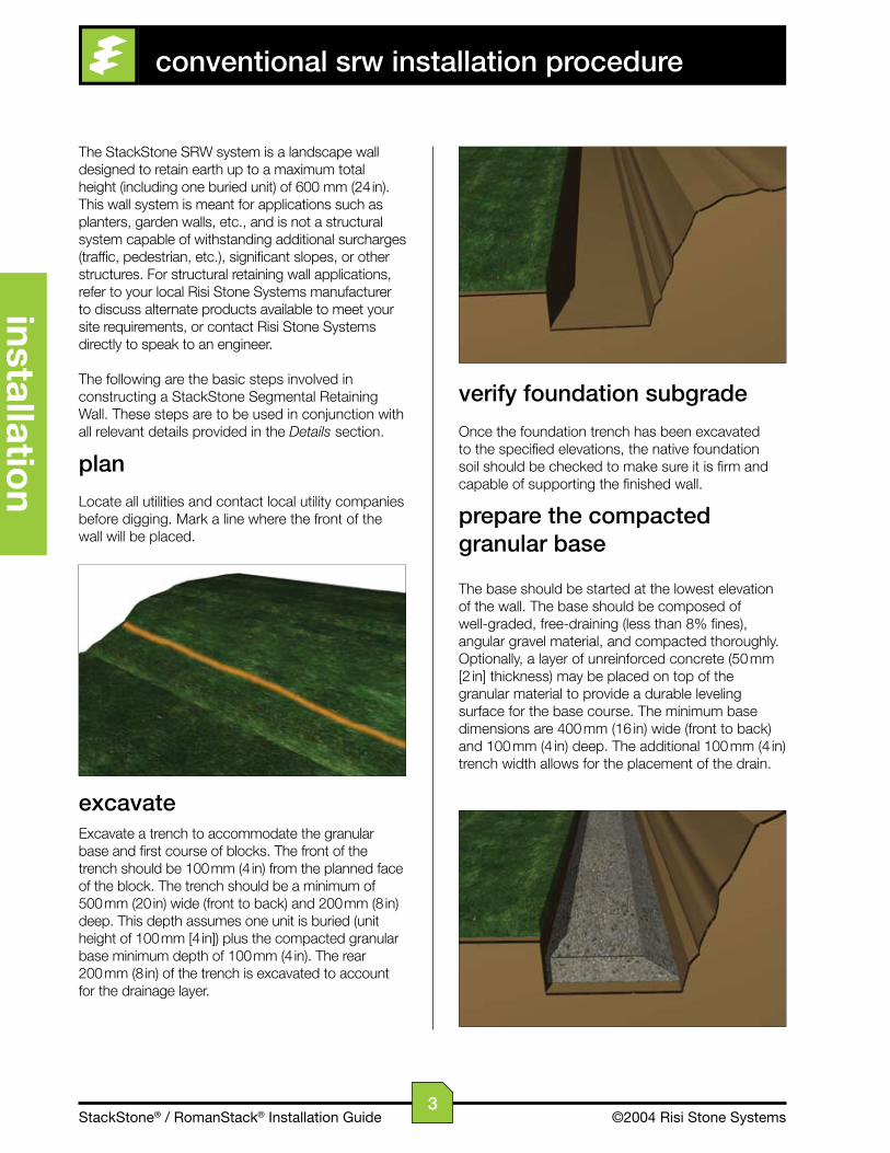
excavateExcavate a trench to accommodate the granular base and first course of blocks. The front of the trench should be 100 mm (4 in) from the planned face of the block. The trench should be a minimum of 500 mm (20 in) wide (front to back) and 200 mm (8 in) deep. This depth assumes one unit is buried (unit height of 100 mm [4 in]) plus the compacted granular base minimum depth of 100 mm (4 in). The rear 200 mm (8 in) of the trench is excavated to account for the drainage layer.
verify foundation subgrade
Once the foundation trench has been excavated to the specified elevations, the native foundation soil should be checked to make sure it is firm and capable of supporting the finished wall.
prepare the compactedgranular base
The base should be started at the lowest elevation of the wall. The base should be composed of well-graded, free-draining (less than 8% fines), angular gravel material, and compacted thoroughly. Optionally, a layer of unreinforced concrete (50 mm [2 in] thickness) may be placed on top of the granular material to provide a durable leveling surface for the base course. The minimum base dimensions are 400 mm (16 in) wide (front to back) and 100 mm (4 in) deep. The additional 100 mm (4 in) trench width allows for the placement of the drain.
3
StackStone® / RomanStack® Installation Guide ©2004 Risi Stone Systems
inst
alla
tio
n
step the base
When the grade in front of the wall slopes up or down, the base must be stepped to compensate. Based on the proposed finished grades in front of the wall, the foundation steps must be located to ensure a minimum of one unit is always buried. The height of each step is 100 mm (4 in) – the height of one course.
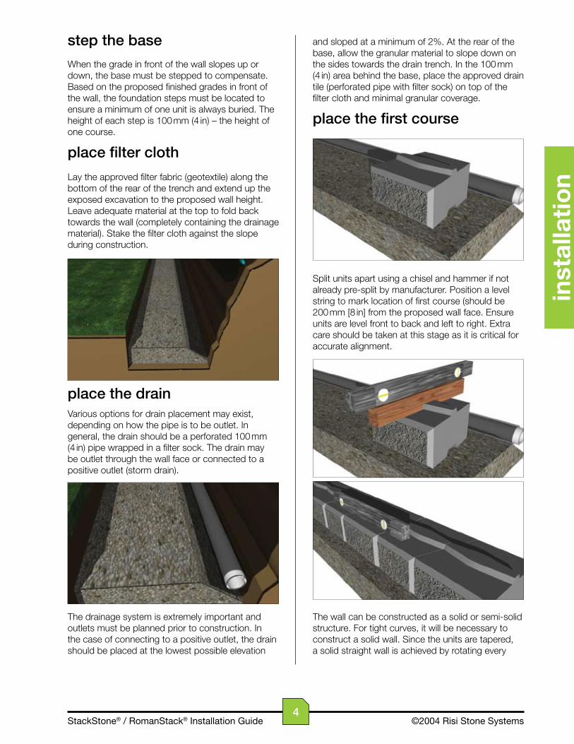
place filter cloth
Lay the approved filter fabric (geotextile) along the bottom of the rear of the trench and extend up the exposed excavation to the proposed wall height. Leave adequate material at the top to fold back towards the wall (completely containing the drainage material). Stake the filter cloth against the slope during construction.
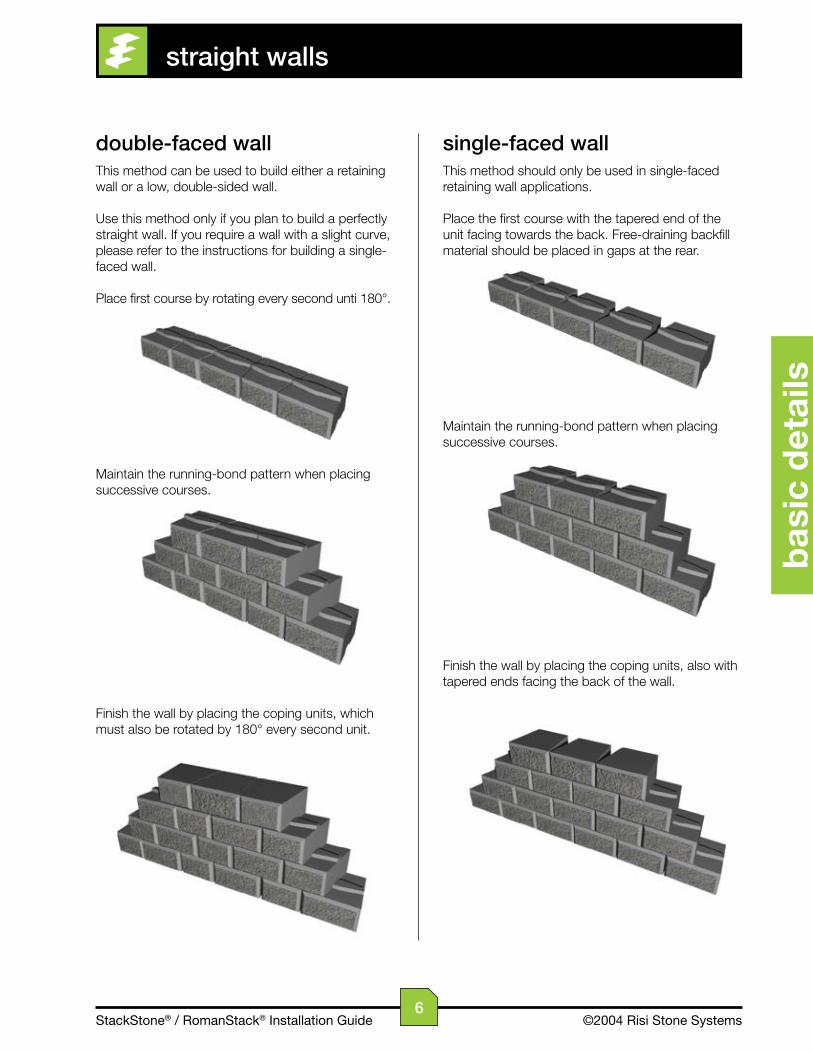
place the drainVarious options for drain placement may exist, depending on how the pipe is to be outlet. In general, the drain should be a perforated 100 mm (4 in) pipe wrapped in a filter sock. The drain may be outlet through the wall face or connected to a positive outlet (storm drain).
The drainage system is extremely important and outlets must be planned prior to construction. In the case of connecting to a positive outlet, the drain should be placed at the lowest possible elevation
and sloped at a minimum of 2%. At the rear of the base, allow the granular material to slope down on the sides towards the drain trench. In the 100 mm (4 in) area behind the base, place the approved drain tile (perforated pipe with filter sock) on top of the filter cloth and minimal granular coverage.
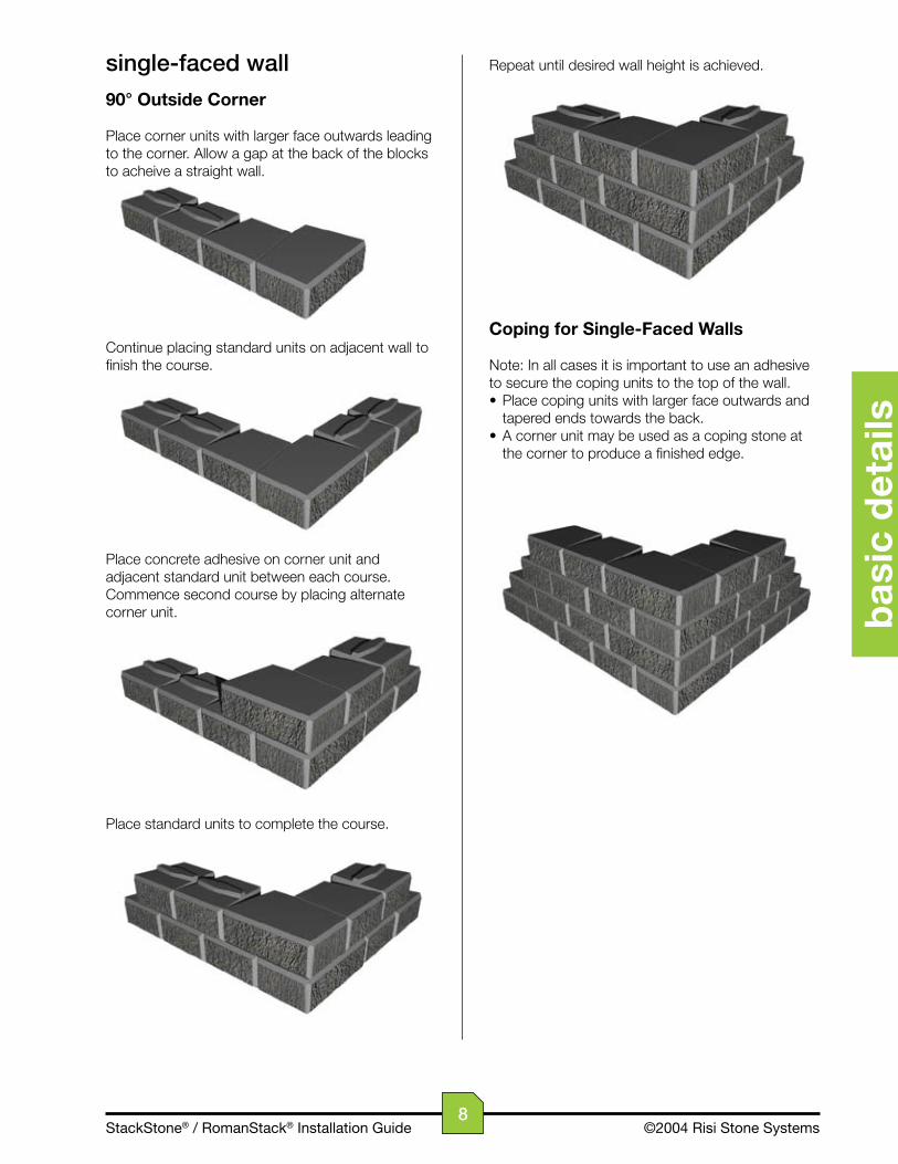
place the first course
Split units apart using a chisel and hammer if not already pre-split by manufacturer. Position a level string to mark location of first course (should be 200 mm [8 in] from the proposed wall face. Ensure units are level front to back and left to right. Extra care should be taken at this stage as it is critical for accurate alignment.
The wall can be constructed as a solid or semi-solid structure. For tight curves, it will be necessary to construct a solid wall. Since the units are tapered, a solid straight wall is achieved by rotating every
4

StackStone® / RomanStack® Installation Guide ©2004 Risi Stone Systems
installation
second block 180˚ along a course. For larger, sweeping curves, the semi-solid wall is formed by simply placing the tapered units adjacent to each other as required to follow the wall alignment.
stack units
Sweep tops of the placed units to remove any debris and stack next course in a running bond pattern so that the middle of the unit is above the joint between adjacent blocks below. Continue stacking courses to a maximum of four courses (400 mm [16 in]) before backfilling.
backfill drainage material
A free-draining, 19 mm (¾ in) clear stone drainage material is placed immediately behind the wall facing and compacted with a light hand tamper. The drainage layer must be a minimum of 300 mm (12 in) thick and separated from the native material by the filter cloth.
continue stacking & backfilling
Continue stacking units and backfilling as described in Steps 10 and 11 until the desired height is reached (to a maximum of five courses – 500 mm [20 in]).
place coping unit
The coping units are identical to standard units, without the tongue. Two lines of concrete adhesive must be applied to the top course in order to fix the coping units in place. Place the coping unit firmly on top of the adhesive, ensuring both surfaces are dry, clean, and free of debris, and apply pressure to secure. Follow adhesive installation guidelines.
encapsulate the drainage layer and finish gradingFold the excess filter fabric over the top of the drainage layer and extend up the back face of the coping unit. Ideally, place an impervious layer of soil on top of the filter fabric and compact manually, providing for the required grading and/or swales. Slope the surface above and below the wall to ensure water will flow away from and not accumulate near the wall units. See the Details section for ideas on tapering down and ending the wall.
5
StackStone® / RomanStack® Installation Guide ©2004 Risi Stone Systems
bas
ic d
etai
ls
straight walls
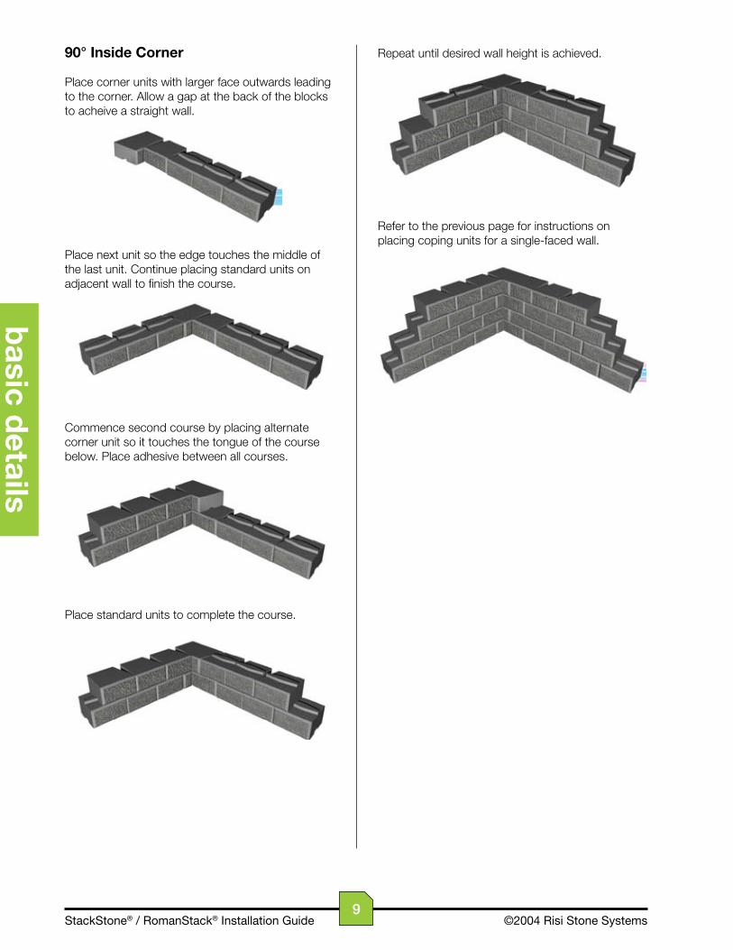
double-faced wallThis method can be used to build either a retaining wall or a low, double-sided wall.
Use this method only if you plan to build a perfectly straight wall. If you require a wall with a slight curve, please refer to the instructions for building a single-faced wall.
Place first course by rotating every second unti 180°.
Maintain the running-bond pattern when placing successive courses.
Finish the wall by placing the coping units, which must also be rotated by 180° every second unit.
single-faced wallThis method should only be used in single-faced retaining wall applications.
Place the first course with the tapered end of the unit facing towards the back. Free-draining backfill material should be placed in gaps at the rear.
Maintain the running-bond pattern when placing successive courses.
Finish the wall by placing the coping units, also with tapered ends facing the back of the wall.
6

StackStone® / RomanStack® Installation Guide ©2004 Risi Stone Systems
basic d
etails
Repeat until desired height is acheived.
The above method can also be used to create an inside 90° corner.
Coping for Double-Faced Walls
Note: In all cases it is important to use an adhesive to secure the coping units to the top of the wall.
• Rotate coping unit 180° every block to achieve a solid course. • A corner unit may be used as a coping stone at the corner to produce a finished edge. • Abut the straight edge of corner unit against back of coping and continue pattern along the adjacent wall.• It may be necessary to remove bumps and buldges from the rough faces in the corner to achieve a tight fit.
corners
double-faced wall
90° Corner
Place units on base course leading to the corner. Rotate blocks 180˚ every other block to acheive a solid wall.
Continue placing base course units on adjacent wall.
Place concrete adhesive on corner unit between each course. Commence second course by placing alternate corner unit.
Place remaining units to complete course.
7
StackStone® / RomanStack® Installation Guide ©2004 Risi Stone Systems
bas
ic d
etai
ls
Repeat until desired wall height is achieved.
Coping for Single-Faced Walls
Note: In all cases it is important to use an adhesive to secure the coping units to the top of the wall.• Place coping units with larger face outwards and tapered ends towards the back.• A corner unit may be used as a coping stone at the corner to produce a finished edge.
single-faced wall
90° Outside Corner
Place corner units with larger face outwards leading to the corner. Allow a gap at the back of the blocks to acheive a straight wall.
Continue placing standard units on adjacent wall to finish the course.
Place concrete adhesive on corner unit and adjacent standard unit between each course. Commence second course by placing alternate corner unit.
Place standard units to complete the course.
8
StackStone® / RomanStack® Installation Guide ©2004 Risi Stone Systems
basic d
etails
Repeat until desired wall height is achieved.
Refer to the previous page for instructions on placing coping units for a single-faced wall.
90° Inside Corner
Place corner units with larger face outwards leading to the corner. Allow a gap at the back of the blocks to acheive a straight wall.
Place next unit so the edge touches the middle of the last unit. Continue placing standard units on adjacent wall to finish the course.
Commence second course by placing alternate corner unit so it touches the tongue of the course below. Place adhesive between all courses.
Place standard units to complete the course.
9
StackStone® / RomanStack® Installation Guide ©2004 Risi Stone Systems
bas
ic d
etai
ls
curves
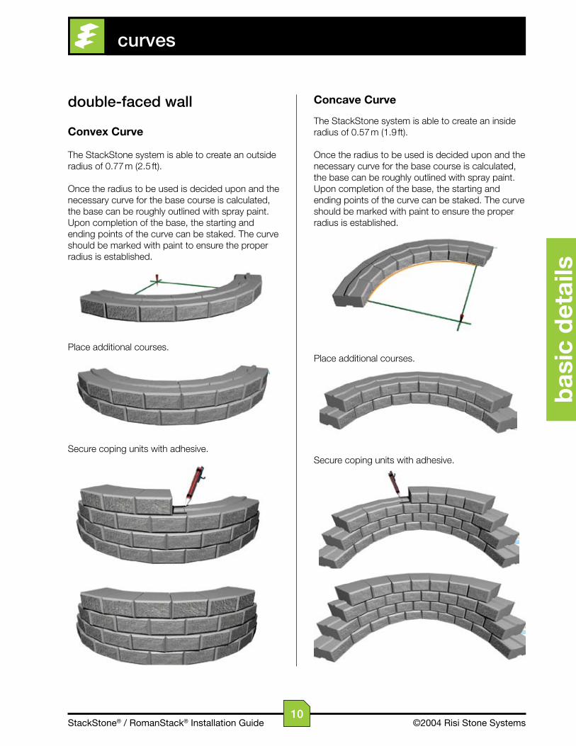
double-faced wall
Convex Curve
The StackStone system is able to create an outside radius of 0.77 m (2.5 ft).
Once the radius to be used is decided upon and the necessary curve for the base course is calculated, the base can be roughly outlined with spray paint. Upon completion of the base, the starting and ending points of the curve can be staked. The curve should be marked with paint to ensure the proper radius is established.
Place additional courses.
Secure coping units with adhesive.
Concave Curve
The StackStone system is able to create an inside radius of 0.57 m (1.9 ft).
Once the radius to be used is decided upon and the necessary curve for the base course is calculated, the base can be roughly outlined with spray paint. Upon completion of the base, the starting and ending points of the curve can be staked. The curve should be marked with paint to ensure the proper radius is established.
Place additional courses.
Secure coping units with adhesive.
10
StackStone® / RomanStack® Installation Guide ©2004 Risi Stone Systems
basic d
etails
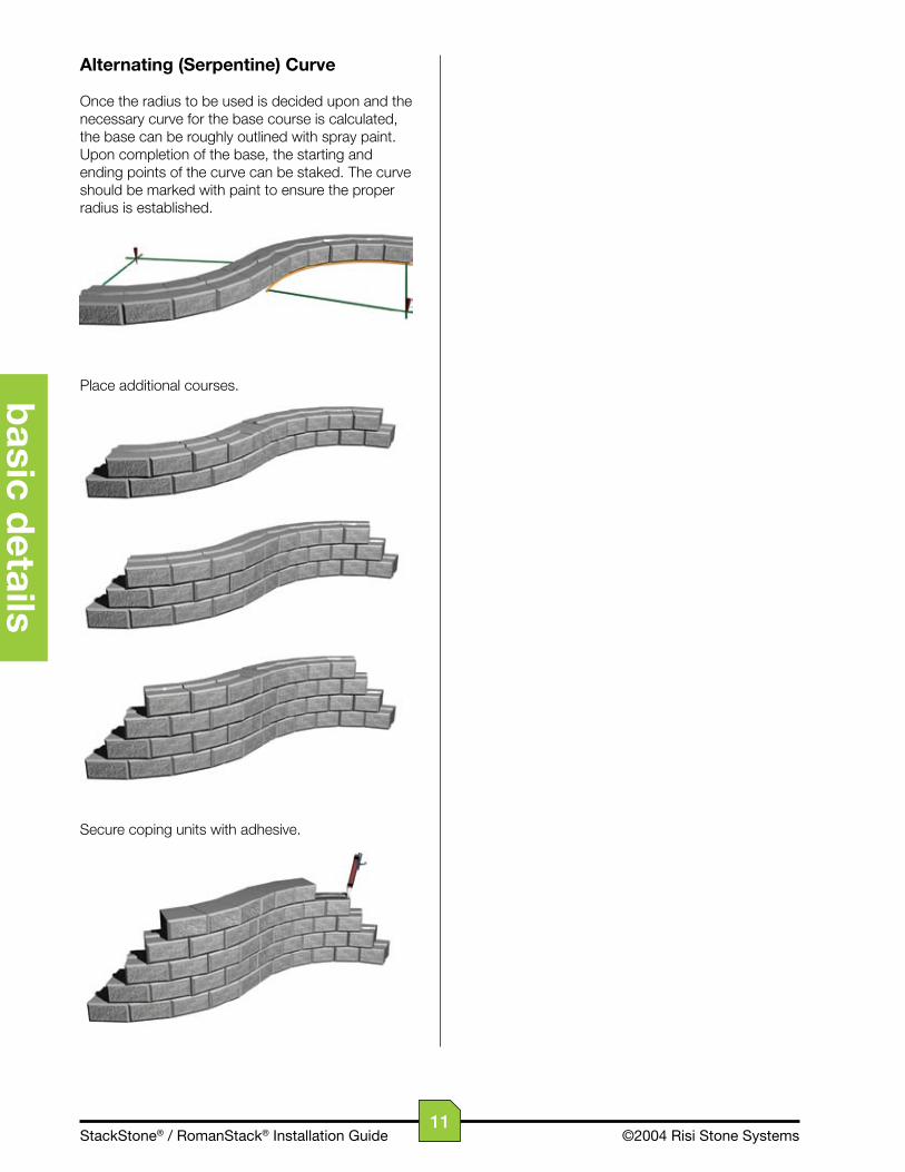
Alternating (Serpentine) Curve
Once the radius to be used is decided upon and the necessary curve for the base course is calculated, the base can be roughly outlined with spray paint. Upon completion of the base, the starting and ending points of the curve can be staked. The curve should be marked with paint to ensure the proper radius is established.
Place additional courses.
Secure coping units with adhesive.
11

StackStone® / RomanStack® Installation Guide ©2004 Risi Stone Systems
bas
ic d
etai
ls
single-faced wall
Convex Curve
The StackStone system is able to create an outside radius of 0.77 m (2.5 ft).
Once the radius to be used is decided upon and the necessary curve for the base course is calculated, the base can be roughly outlined with spray paint. Upon completion of the base, the starting and ending points of the curve can be staked. The curve should be marked with paint to ensure the proper radius is established.
Place additional courses.
Secure coping units with adhesive.
Concave Curve
The StackStone system is able to create an inside radius of 0.57 m (1.9 ft).
Once the radius to be used is decided upon and the necessary curve for the base course is calculated, the base can be roughly outlined with spray paint. Upon completion of the base, the starting and ending points of the curve can be staked. The curve should be marked with paint to ensure the proper radius is established.
Place additional courses.
Secure coping units with adhesive.
12
StackStone® / RomanStack® Installation Guide ©2004 Risi Stone Systems
basic d
etails
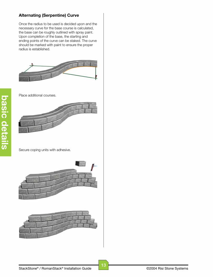
Alternating (Serpentine) Curve
Once the radius to be used is decided upon and the necessary curve for the base course is calculated, the base can be roughly outlined with spray paint. Upon completion of the base, the starting and ending points of the curve can be staked. The curve should be marked with paint to ensure the proper radius is established.
Place additional courses.
Secure coping units with adhesive.
13
StackStone® / RomanStack® Installation Guide ©2004 Risi Stone Systems
spec
ific
det
ails
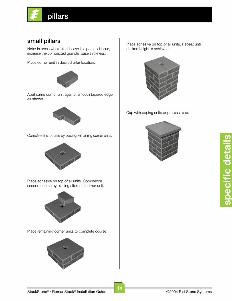
Place adhesive on top of all units. Repeat until desired height is achieved.
Cap with coping units or pre-cast cap.
small pillarsNote: In areas where frost heave is a potential issue, increase the compacted granular base thickness.
Place corner unit in desired pillar location.
Abut same corner unit against smooth tapered edge as shown.
Complete first course by placing remaining corner units.
Place adhesive on top of all units. Commence second course by placing alternate corner unit.
Place remaining corner units to complete course.
pillars
14
StackStone® / RomanStack® Installation Guide ©2004 Risi Stone Systems
specifi
c details
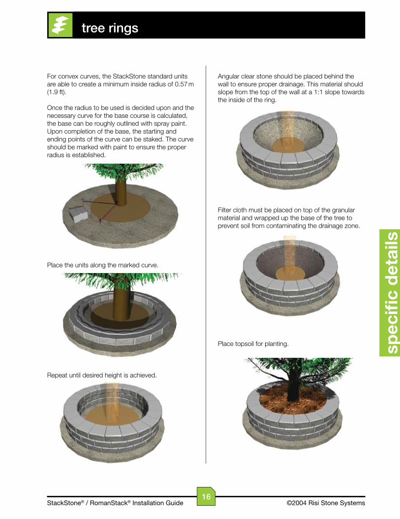
Repeat until desired height is achieved. The maximum height is 4 ft, but will depend on the site conditions.
Finish with pre-cast cap.
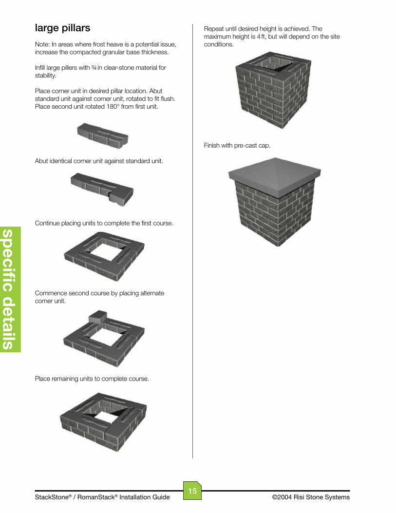
large pillars
Note: In areas where frost heave is a potential issue, increase the compacted granular base thickness.
Infill large pillers with ¾ in clear-stone material for stability.
Place corner unit in desired pillar location. Abut standard unit against corner unit, rotated to fit flush. Place second unit rotated 180° from first unit.
Abut identical corner unit against standard unit.
Continue placing units to complete the first course.
Commence second course by placing alternate corner unit.
Place remaining units to complete course.
15
StackStone® / RomanStack® Installation Guide ©2004 Risi Stone Systems
subsection
spec
ific
det
ails
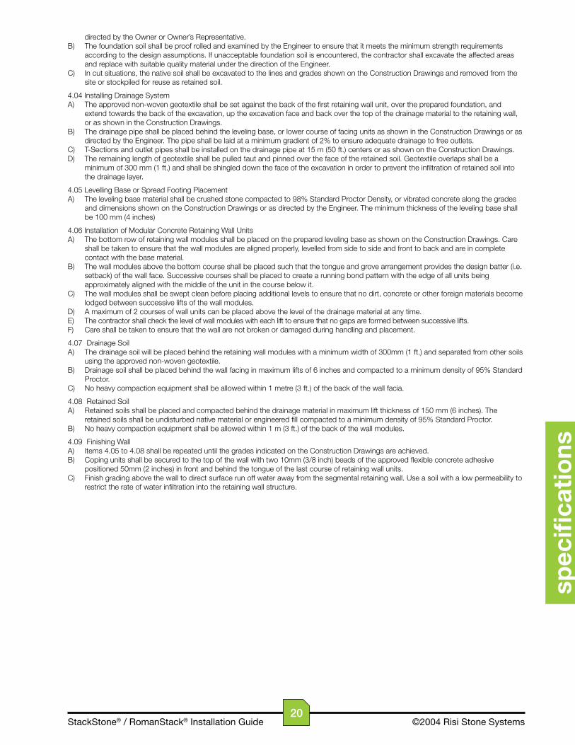
Angular clear stone should be placed behind the wall to ensure proper drainage. This material should slope from the top of the wall at a 1:1 slope towards the inside of the ring.
Filter cloth must be placed on top of the granular material and wrapped up the base of the tree to prevent soil from contaminating the drainage zone.
Place topsoil for planting.
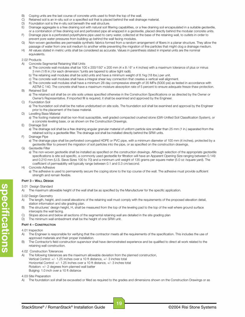
For convex curves, the StackStone standard units are able to create a minimum inside radius of 0.57 m (1.9 ft).
Once the radius to be used is decided upon and the necessary curve for the base course is calculated, the base can be roughly outlined with spray paint. Upon completion of the base, the starting and ending points of the curve can be staked. The curve should be marked with paint to ensure the proper radius is established.
Place the units along the marked curve.
Repeat until desired height is achieved.
tree rings
16

StackStone® / RomanStack® Installation Guide ©2004 Risi Stone Systems
subsection
specifi
c details
terminating the wallThe retaining wall must be terminated to prevent the washout of the granular infill placed behind the wall. This can be done by • Tapering down to grade (as shown below) or
• Returning into the slope with a curve or corner
With corner unit
Without corner unit
abutting into existing structureThe wall should abut the existing structure with a 25 mm asphalt-impregnated fibre board expansion joint. Cut standard units or simple corner units as required to maintain the running bond pattern.
window wellWindow wells can be constructed to a maximum total height of 500 mm (20 in). The wall should abut the building with a 25 mm asphalt-impregnated fibre board.
Refer to Details – Curves for construction directions.
fire pitFire pits can be constructed below ground or above (as shown below). Various manufacturers sell fire pit kits that include a grill that can be placed on the pit.
Refer to Details – Curves for construction directions.
other applications
17

StackStone® / RomanStack® Installation Guide ©2004 Risi Stone Systems
conventional retaining wall specifications
spec
ifica
tio
ns
Part1–General
1.01 DescriptionA) The work covered by this section includes the furnishing of all labor, materials, equipment and incidentals for the design, inspection and construction of a modular concrete retaining wall including drainage system as shown on the Construction Drawings and as described by the Contract Specifications. The work included in this section consists of, but is not limited, to the following: a) Design, inspection and certification by a registered professional engineer. b) Excavation and foundation soil preparation. c) Furnishing and placement of the leveling base. d) Furnishing and placement of the drainage system. e) Furnishing and placement of geotextiles. f) Furnishing and placement of segmental retaining wall facing units. g) Furnishing and compaction of drainage and retained soils.
1.02 Related WorkA) Section 02100 - Site PreparationB) Section 02200 - Earthwork
1.03 Reference StandardsA) Engineering Design a) NCMA Design Manual for Segmental Retaining Walls, Second Edition. b) NCMA TEK 2-4 – Specifications for Segmental Retaining Wall Units. c) ASTM D 6919 – Determination of Shear Strength between Segmental Concrete Units.B) Segmental Retaining Wall Units a) ASTM C 140 – Sampling and Testing Concrete Masonry Units b) ASTM C 1262 – Evaluating the Freeze – Thaw Durability of Manufactured Concrete Masonry Units and Related Concrete Units. c) ASTM C1372 - Standard Specification for Segmental Retaining wall UnitsC) Geotextile Filter a) ASTM D 4751 – Standard Test Method for Apparent Opening SizeD) Soils a) ASTM D 698 – Moisture Density Relationship for Soils, Standard Method b) ASTM D 422 – Gradation of Soils c) ASTM D 424 – Atterberg Limits of Soils d) ASTM D G51 – Soil pHE) Drainage Pipe a) ASTM D 3034 – Specification for Polyvinyl Chloride (PVC) Plastic Pipe b) ASTM D 1248 – Specification for Corrugated Plastic PipeF) Where specifications and reference documents conflict, the Owner or Owner's representative shall make the final determination of applicable document.
1.04 Approved ProductsA) StackStone Segmental Retaining Wall System as supplied by the Risi Stone Systems Authorized Manufacturer.B) Colour to be [_______].
1.05 The InstallerA) The term Installer shall refer to the individual or firm who will be installing the retaining wall. B) The Installer must have the necessary experience for the project and have successfully completed projects of similar scope and size.
1.06 Delivery, Material Handling and StorageA) The Installer shall check all materials delivered to the site to ensure that the correct materials have been received and are in good condition.B) The Installer shall store and handle all materials in accordance with manufacturer’s recommendations and in a manner to prevent deterioration or damage due to moisture, temperature changes, contaminants, breaking, chipping or other causes.
1.07 Measurement for PaymentA) Payment for earthworks to prepare the site for the retaining wall construction will be based on the contract unit price per cubic metre (or cubic yard) for site cut and fill earthwork as detailed in the Site Plan. Additional earthwork as directed and approved in writing by the Owner, or Owner’s representative, shall be paid for under a separate pay item.B) Payment for the retaining wall system will be based on the contract price per square metre (or square foot) of vertical wall face area as shown on the construction drawings. The vertical wall face area shall be measured from the top of the base or footing to the top of the coping course multiplied by the length of the wall. The contract unit price shall include the cost of all engineering, labour, materials, and equipment used to install the leveling base or spread footing, wall modules, drainage materials, retained soil and site clean up. Additional items as directed and approved in writing by the Owner, or Owner’s representative, shall be paid for under a separate pay item.
Part2–Materials
2.01 DefinitionsA) Modular concrete retaining wall units are dry-cast solid concrete units that form the external facia of a modular unit retaining wall system.
18
StackStone® / RomanStack® Installation Guide ©2004 Risi Stone Systems
specifi
cations
B) Coping units are the last course of concrete units used to finish the top of the wall.C) Retained soil is an in-situ soil or a specified soil that is placed behind the wall drainage material.D) Foundation soil is the in-situ soil beneath the wall structure.E) Drainage aggregate is a free draining soil with natural soil filtering capabilities, or a free draining soil encapsulated in a suitable geotextile, or a combination of free draining soil and perforated pipe all wrapped in a geotextile, placed directly behind the modular concrete units.F) Drainage pipe is a perforated polyethylene pipe used to carry water, collected at the base of the retaining wall, to outlets in order to prevent pore water pressures from building up behind the wall facing modules.G) Non-woven geotextiles are permeable synthetic fabrics formed from a random arrangement of fibers in a planar structure. They allow the passage of water from one soil medium to another while preventing the migration of fine particles that might clog a drainage medium.H) All values stated in metric units shall be considered as accurate. Values in parenthesis stated in imperial units are the nominal equivalents.
2.02 ProductsA) Concrete Segmental Retaining Wall Units a) The concrete wall modules shall be 100 x 200/150* x 200 mm (4 x 8 / 6* x 4 inches) with a maximum tolerance of plus or minus 3 mm (1/8 in.) for each dimension.*(units are tapered to allow tight radii). b) The retaining wall modules shall be solid units and have a minimum weight of 8.1kg (18 lbs.) per unit. c) The concrete wall modules shall have a integral shear key connection that creates a vertical wall alignment. d) The concrete wall modules shall have a minimum 28-day compressive strength of 35 MPa (5000 psi) as tested in accordance with ASTM C 140. The concrete shall have a maximum moisture absorption rate of 5 percent to ensure adequate freeze-thaw protection.B) Retained Soil a) The retained soil shall be on site soils unless specified otherwise in the Construction Specifications or as directed by the Owner or Owner’s Representative. If imported fill is required, it shall be examined and approved by the Engineer.C) Foundation Soil a) The foundation soil shall be the native undisturbed on site soils. The foundation soil shall be examined and approval by the Engineer prior to the placement of the base material.D) Levelling Base Material a) The footing material shall be non-frost susceptible, well graded compacted crushed stone (GW-Unified Soil Classification System), or a concrete leveling base, or as shown on the Construction Drawings.E) Drainage Soil a) The drainage soil shall be a free draining angular granular material of uniform particle size smaller than 25 mm (1 in.) separated from the retained soil by a geotextile filter. The drainage soil shall be installed directly behind the SRW units.F) Drainage Pipe a) The drainage pipe shall be perforated corrugated HDPE or PVC pipe, with a minimum diameter of 100 mm (4 inches), protected by a geotextile filter to prevent the migration of soil particles into the pipe, or as specified on the construction drawings.G) Geotextile Filter a) The non-woven geotextile shall be installed as specified on the construction drawings. Although selection of the appropriate geotextile specifications is site soil specific, a commonly used geotextile for filtration will have an Apparent Opening Size ranging between 0.149 and 0.210 mm (U.S. Sieve Sizes 100 to 70) and a minimum unit weight of 135 grams per square meter (5.0 oz /square yard). The coefficient of permeability will typically range between 0.1 and 0.3 cm/second.H) Concrete Adhesive a) The adhesive is used to permanently secure the coping stone to the top course of the wall. The adhesive must provide sufficient strength and remain flexible.
Part3–WallDesiGn
3.01 Design StandardA) The maximum allowable height of the wall shall be as specified by the Manufacturer for the specific application.
3.02 Design GeometryA) The length, height, and overall elevations of the retaining wall must comply with the requirements of the proposed elevation detail, station information and site grading plan.B) The structures’ design height, H, shall be measured from the top of the leveling pad to the top of the wall where ground surface intercepts the wall facing.C) Slopes above and below all sections of the segmental retaining wall are detailed in the site grading planD) The minimum wall embedment shall be the height of one SRW unit.
Part4–ConstruCtion
4.01 InspectionA) The Engineer is responsible for verifying that the contractor meets all the requirements of the specification. This includes the use of approved materials and their proper installation.B) The Contractor’s field construction supervisor shall have demonstrated experience and be qualified to direct all work related to the retaining wall construction.
4.02 Construction TolerancesA) The following tolerances are the maximum allowable deviation from the planned construction, Vertical Control: +/- 1.25 inches over a 10 ft distance, +/- 3 inches total Horizontal Control: +/- 1.25 inches over a 10 ft distance, +/- 3 inches total Rotation: +/- 2 degrees from planned wall batter Bulging: 1.0 inch over a 10 ft distance
4.03 Site PreparationA) The foundation soil shall be excavated or filled as required to the grades and dimensions shown on the Construction Drawings or as
19
StackStone® / RomanStack® Installation Guide ©2004 Risi Stone Systems
spec
ifica
tio
ns
directed by the Owner or Owner’s Representative.B) The foundation soil shall be proof rolled and examined by the Engineer to ensure that it meets the minimum strength requirements according to the design assumptions. If unacceptable foundation soil is encountered, the contractor shall excavate the affected areas and replace with suitable quality material under the direction of the Engineer.C) In cut situations, the native soil shall be excavated to the lines and grades shown on the Construction Drawings and removed from the site or stockpiled for reuse as retained soil.
4.04 Installing Drainage SystemA) The approved non-woven geotextile shall be set against the back of the first retaining wall unit, over the prepared foundation, and extend towards the back of the excavation, up the excavation face and back over the top of the drainage material to the retaining wall, or as shown in the Construction Drawings.B) The drainage pipe shall be placed behind the leveling base, or lower course of facing units as shown in the Construction Drawings or as directed by the Engineer. The pipe shall be laid at a minimum gradient of 2% to ensure adequate drainage to free outlets.C) T-Sections and outlet pipes shall be installed on the drainage pipe at 15 m (50 ft.) centers or as shown on the Construction Drawings.D) The remaining length of geotextile shall be pulled taut and pinned over the face of the retained soil. Geotextile overlaps shall be a minimum of 300 mm (1 ft.) and shall be shingled down the face of the excavation in order to prevent the infiltration of retained soil into the drainage layer.
4.05 Levelling Base or Spread Footing PlacementA) The leveling base material shall be crushed stone compacted to 98% Standard Proctor Density, or vibrated concrete along the grades and dimensions shown on the Construction Drawings or as directed by the Engineer. The minimum thickness of the leveling base shall be 100 mm (4 inches)
4.06 Installation of Modular Concrete Retaining Wall UnitsA) The bottom row of retaining wall modules shall be placed on the prepared leveling base as shown on the Construction Drawings. Care shall be taken to ensure that the wall modules are aligned properly, levelled from side to side and front to back and are in complete contact with the base material.B) The wall modules above the bottom course shall be placed such that the tongue and grove arrangement provides the design batter (i.e. setback) of the wall face. Successive courses shall be placed to create a running bond pattern with the edge of all units being approximately aligned with the middle of the unit in the course below it.C) The wall modules shall be swept clean before placing additional levels to ensure that no dirt, concrete or other foreign materials become lodged between successive lifts of the wall modules.D) A maximum of 2 courses of wall units can be placed above the level of the drainage material at any time.E) The contractor shall check the level of wall modules with each lift to ensure that no gaps are formed between successive lifts.F) Care shall be taken to ensure that the wall are not broken or damaged during handling and placement.
4.07 Drainage SoilA) The drainage soil will be placed behind the retaining wall modules with a minimum width of 300mm (1 ft.) and separated from other soils using the approved non-woven geotextile.B) Drainage soil shall be placed behind the wall facing in maximum lifts of 6 inches and compacted to a minimum density of 95% Standard Proctor.C) No heavy compaction equipment shall be allowed within 1 metre (3 ft.) of the back of the wall facia.
4.08 Retained SoilA) Retained soils shall be placed and compacted behind the drainage material in maximum lift thickness of 150 mm (6 inches). The retained soils shall be undisturbed native material or engineered fill compacted to a minimum density of 95% Standard Proctor.B) No heavy compaction equipment shall be allowed within 1 m (3 ft.) of the back of the wall modules.
4.09 Finishing WallA) Items 4.05 to 4.08 shall be repeated until the grades indicated on the Construction Drawings are achieved.B) Coping units shall be secured to the top of the wall with two 10mm (3/8 inch) beads of the approved flexible concrete adhesive positioned 50mm (2 inches) in front and behind the tongue of the last course of retaining wall units.C) Finish grading above the wall to direct surface run off water away from the segmental retaining wall. Use a soil with a low permeability to restrict the rate of water infiltration into the retaining wall structure.
20

StackStone® / RomanStack® Installation Guide ©2004 Risi Stone Systems
glossary
glo
ssary
Adhesive
Material used to bond the units together. Ask manufacturer for recommended brands.
Aggregate
Materials such as sand, gravel and crushed stone used with cement to make concrete.
Batter
Apparent inclination, from vertical, of the retaining wall face due to the units’ setback.
Compaction
The process of reducing the voids in newly placed soils by vibration, kneading, or tamping to ensure the maximum density and strength in the soil.
Coping
Top course of units on a wall. Provides a finished appearance and ties the wall together.
Concave Curve
The surface of the wall is curved like the interior of a sphere or circle.
Convex Curve
The surface of the wall is curved like the exterior of a sphere or circle.
Cut Bank
The enbankment of site soil created before the retaining wall is installed.
Density
Measure of the quantity of mass per unit volume. Dimensions are kg/cu.m or lb/cu.ft.
Drainage Fill
A poorly graded aggregate material with a high permeability and porosity (e.g. clear stone).
Facia/Facing
The assembled modular concrete units that form the exterior face of the retaining wall.
Filter Cloth
A continuous sheet of flexible, permeable fabric used to separate, filtrate, and reinforce.
Foundation Soil
The soil upon which the base of the wall is placed.
Conventional Segmental Retaining Wall
An earth retaining structure that uses its mass to resist the movement of the soil mass behind the structure.
Retained Soil
Site soil in a cut bank or soil material placed and compacted behind the wall structure.
Running Bond
Pattern created by stacking units so the vertical joints are offset one half unit from the course below.
Slope
A surface that inclines up or down (i.e. not horizontal).
SRW
Segmental Retaining Wall
Surcharge
Loads or extra weight placed on the soil above and behind the retaining wall (e.g. traffic).
Wall Embedment
Depth of retaining wall that is buried. Distance from top of base to lower surface grade.
Weight
Measure of gravity force on an object.
21
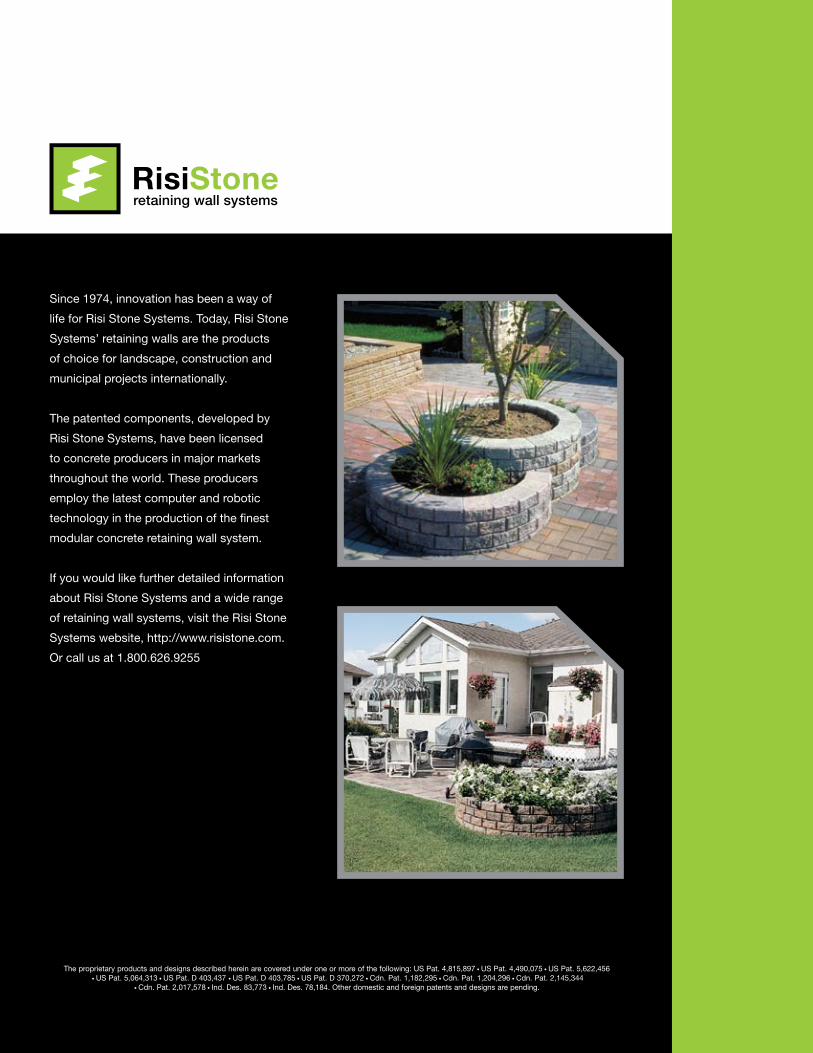
Since 1974, innovation has been a way of
life for Risi Stone Systems. Today, Risi Stone
Systems’ retaining walls are the products
of choice for landscape, construction and
municipal projects internationally.
The patented components, developed by
Risi Stone Systems, have been licensed
to concrete producers in major markets
throughout the world. These producers
employ the latest computer and robotic
technology in the production of the finest
modular concrete retaining wall system.
If you would like further detailed information
about Risi Stone Systems and a wide range
of retaining wall systems, visit the Risi Stone
Systems website, http://www.risistone.com.
Or call us at 1.800.626.9255
The proprietary products and designs described herein are covered under one or more of the following: US Pat. 4,815,897 • US Pat. 4,490,075 • US Pat. 5,622,456 • US Pat. 5,064,313 • US Pat. D 403,437 • US Pat. D 403,785 • US Pat. D 370,272 • Cdn. Pat. 1,182,295 • Cdn. Pat. 1,204,296 • Cdn. Pat. 2,145,344
• Cdn. Pat. 2,017,578 • Ind. Des. 83,773 • Ind. Des. 78,184. Other domestic and foreign patents and designs are pending.
RisiStoneretaining wall systems
®