stacker cranes for pallets cze · pdf file · 2017-06-23machine in order extract or...
TRANSCRIPT

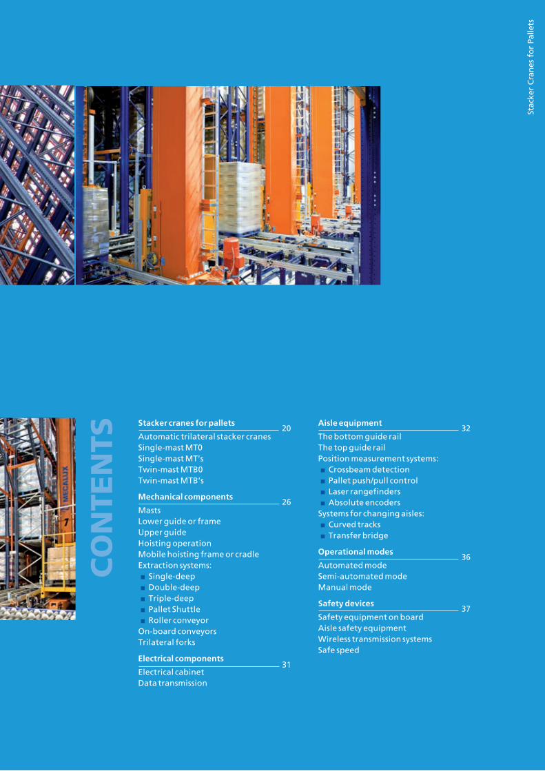
Stacker Cranes for Pallets

Stacker cranes are machines designed for
the automated storage of pallets. They
travel along the aisles of the warehouse,
carrying out the storage, placement and
retrieval of goods.
Stac
ker
Cra
nes
fo
r Pa
llets
Stacker cranes for pallets
Automatic trilateral stacker cranesSingle-mast MT0Single-mast MT’sTwin-mast MTB0Twin-mast MTB’s
Mechanical components
MastsLower guide or frameUpper guideHoisting operation Mobile hoisting frame or cradleExtraction systems:■ Single-deep■ Double-deep■ Triple-deep■ Pallet Shuttle■ Roller conveyor
On-board conveyorsTrilateral forks
Electrical components
Electrical cabinetData transmission
Aisle equipment
The bottom guide railThe top guide rail Position measurement systems:■ Crossbeam detection ■ Pallet push/pull control■ Laser rangefinders■ Absolute encoders
Systems for changing aisles:■ Curved tracks■ Transfer bridge
Operational modes
Automated modeSemi-automated modeManual mode
Safety devices
Safety equipment on boardAisle safety equipmentWireless transmission systemsSafe speed
CONTE
NTS
20
26
31
32
36
37

20 Automated warehouses
Stacker cranes are machines designed for the automated storage of materials by means of automated mechanical movements. Storage and retrieval is carried out in the same movement (known as a combined cycle). This increases productivity in the installation, as well as reducing the resources required for it to function.
In order to move the loads in the warehouse, the stacker cranes can carry out three types of movements:
■ Down-aisle: Moving along the aisle on a rail
■ Vertical: Up and down the mast of the stacker crane.
■ Cross-aisle: across the depth of the racks, performed by the extraction systems fitted to the cradle of the machine in order extract or position a pallet.
The principal types of stacker cranes are:
■ Single-mast (recommended for loads of up to 1,500 kg).
■ Twin-mast (advisable for moving two loads of up to 1,000 kg each, or one large load).
Mecalux stacker cranes are state-of-the-art machines with commands operated by vector-controlled frequency inverters with positioning control by means of laser rangefinders and intelligent control by PC or PLC.
The range of stacker cranes adapts easily to the needs of each warehouse in terms of load capacity, dimensions, building height and cycle times, and so is able to cover a broad array of applications.
All of these systems can be adapted to special working conditions such as freezing temperatures (-30 ºC), extreme humidity or special features, including the possibility of increasing standard working speeds.
Furthermore, it has electronic energy recovery devices, which account for considerable savings in monthly energy consumption.
Mecalux stacker cranes have proven their efficiency in sectors as diverse as the food industry, the car industry, pharmaceuticals, spare parts, metallurgy, chemicals and public administration.
STACKER CRANES FOR PALLETS

21www.mecalux.cz
Stac
ker C
rane
s fo
r Pal
lets
Automatic trilateral stacker cranes Designed to handle non-operator automated systems in free-standing warehouses using conventional racking without the need for upper guide rails. Its main advantages are:
CHARACTERISTICS
15,000 mm
No
1,200 kg
1,300 x 1,100 x 2,300 mm
Trilateral electric forks
100 m/min
0.3 m/s2
38 m/min
0.3 m/s2
Transfer bridge without pit
Yes
Yes
Maximum height - single deep
Upper guide rail rail
Maximum weight over entire height
Max. load dimensions
Type of extractor
Max. drive speed (Vx)
Max. drive acceleration (ax)
Max. lifting speed (Vy)
Max. lifting acceleration (ay)
Aisle changing system
Europallets of 800 mm and 1,000 mm
GMA or closed CHEP pallets
■ Load retrieval on three sides with bottom dimensions under 100 mm on the sides and 0 mm when retrieving loads from the front.
■ Does not require upper guide rail, meaning it can be used in existing warehouses without having to reinforce the racks.
■ Eight-wheel running gear, making aisle changes over the transfer bridge easy, without any need to install a pit.
■ Fully automated operation that connects to Easy WMS.
22 Automated warehouses
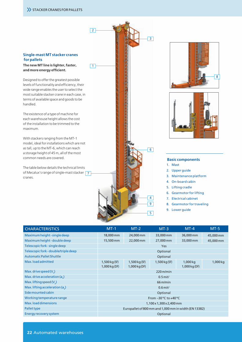
STACKER CRANES FOR PALLETS>>
3
1
5
7
Basic components1. Mast
2. Upper guide
3. Maintenance platform
4. On-board cabin
5. Lifting cradle
6. Gearmotor for lifting
7. Electrical cabinet
8. Gearmotor for traveling
9. Lower guide
Single-mast MT stacker cranes for pallets The new MT line is lighter, faster, and more energy efficient.
Designed to offer the greatest possible levels of functionality and efficiency, their wide range enables the user to select the most suitable stacker crane in each case, in terms of available space and goods to be handled.
The existence of a type of machine for each warehouse height allows the cost of the installation to be trimmed to the maximum.
With stackers ranging from the MT-1 model, ideal for installations which are not as tall, up to the MT-6, which can reach a storage height of 45 m, all of the most common needs are covered.
The table below details the technical limits of Mecalux’s range of single-mast stacker cranes.
2
8
4
6
9
CHARACTERISTICS MT-1 MT-2 MT-3
18,000 mm
15,500 mm
24,000 mm
22,000 mm
33,000 mm
27,000 mm
Maximum height - single deep
Maximum height - double deep
Telescopic fork - single deep
Telescopic fork - double/triple deep
Automatic Pallet Shuttle
Max. load admitted
Max. drive speed (Vx)
Max. drive acceleration (ax)
Max. lifting speed (Vy)
Max. lifting acceleration (ay)
Side mounted cabin
Working temperature range
Max. load dimensions
Pallet type
Energy recovery system
MT-5
45,000 mm
45,000 mm
MT-4
36,000 mm
33,000 mm
Yes
Optional
Optional
1,500 kg (SF) 1,500 kg (SF) 1,500 kg (SF) 1,000 kg 1,000 kg 1,000 kg (DF) 1,000 kg (DF) 1,000 kg (DF)
220 m/min
0.5 m/s2
66 m/min
0.6 m/s2
Optional
From –30 ºC to +40 ºC
1,100 x 1,300 x 2,400 mm
Europallet of 800 mm and 1,000 mm in width (EN 13382)
Optional

23www.mecalux.cz
Stac
ker C
rane
s fo
r Pal
lets
Twin-mast stacker cranes (MTB0) Created for simple storage systems, there are fewer features but it is just as safe, and has high capacity without the need for a great deal of space. Twin-mast stacker cranes are affordable and energy efficient. Their main advantages are:
■ Depositing and picking up loads can be completed at a very low level, with a connection to automated conveyors.
■ Low energy consumption.
■ Fully automated operation, connecting to Easy WMS.
CHARACTERISTICS
18,000 mm
Yes
1,500 kg
1,300 x 1,100 x 2,400 mm
Yes
Optional
Optional
Telescopic fork - double deep
120 m/min
0.3 m/s2
38 m/min
0.3 m/s2
Yes
Maximum height
Upper guide rail
Maximum weight over entire height
Max. load dimensions
Telescopic fork - single deep
Telescopic fork - double/triple deep
Automatic Pallet Shuttle
Type of extractor
Max. drive speed (Vx)
Max. drive acceleration (ax)
Max. lifting speed (Vy)
Max. lifting acceleration (ay)
Europallets of 800 and 1,000 mm/GMA pallets
24 Automated warehouses
STACKER CRANES FOR PALLETS>>
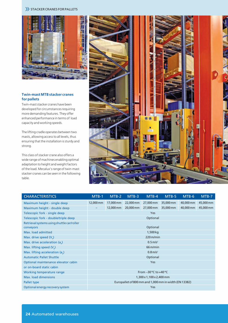
Twin-mast MTB stacker cranes for pallets Twin-mast stacker cranes have been developed for circumstances requiring more demanding features. They offer enhanced performance in terms of load capacity and working speeds.
The lifting cradle operates between two masts, allowing access to all levels, thus ensuring that the installation is sturdy and strong.
This class of stacker crane also offers a wide range of machines enabling optimal adaptation to height and weight factors of the load. Mecalux’s range of twin-mast stacker cranes can be seen in the following table.
CHARACTERISTICS MTB-1 MTB-2 MTB-3 MTB-4
17,000 mm
12,000 mm
12,000 mm
–
22,000 mm
20,000 mm
27,000 mm
27,000 mm
35,000 mm
35,000 mm
Maximum height - single deep
Maximum height - double deep
Telescopic fork - single deep
Telescopic fork - double/triple deep
Retrieval systems using shuttle car/rollerconveyors
Max. load admitted
Max. drive speed (Vx)
Max. drive acceleration (ax)
Max. lifting speed (Vy)
Max. lifting acceleration (ay)
Automatic Pallet Shuttle
Optional maintenance elevator cabin
or on-board static cabin
Working temperature range
Max. load dimensions
Pallet type
Optional energy recovery system
MTB-5
40,000 mm
40,000 mm
45,000 mm
45,000 mm
MTB-6
Yes
Optional
Optional
1,500 kg
220 m/min
0.5 m/s2
66 m/min
0.8 m/s2
Optional
Yes
From –30 ºC to +40 ºC
1,300 x 1,100 x 2,400 mm
Europallet of 800 mm and 1,000 mm in width (EN 13382)
Yes
MTB-7

25www.mecalux.cz
Stac
ker C
rane
s fo
r Pal
lets
2
3
5
4
7
2
3
6
5
1
7
8
8
9
Basic components1. Columns
2. Upper guide
3. Maintenance platform
4. On-board cabin
5. Lifting cradle
6. Gearmotor for lifting
7. Electrical cabinet
8. Gearmotor for traveling
9. Lower guide

26 Automated warehouses
4
5
1
2
3
The design of the stacker cranes minimises the forces transmitted to the structure on which they are supported. In the long run this prevents the rack and warehouse structure from being damaged.Stacker cranes are made up of the following components: Masts, lower guide or frame, upper guide, hoisting control and the mobile hoisting frame or cradle.
MastsThe masts can be made up of structural tubes or box-girders. They are manufactured from highly resistant steel sheets which have been specially shaped and welded together to form a rectangular-shaped box-girder.
1. The box girder is reinforced inside by means of lattice ribbing fitted horizontally and diagonally, giving the
column greater resistance to torsion and bending. The structure formed by the two columns and the two frames strengthens the stacker crane, ensuring it is sturdy and stable when moving.
2. The masts come with vertical tracks bolted on both sides that guide a hoisting cradle. These tracks are made of highly resistant calibrated rectangular profiles.
3. A plate of welded steel is bolted at the base of the column to the bottom frame. These machine-cut steel plates are welded to both edges of the mast, and then bolted to the top and bottom guide bases.
4. Under the hoisting group platform there is a completely enclosed and secure control cabin, along with an electrical control panel.
5. Maintenance access is via the emergency ladder installed along the column’s flank, which comes equipped with a safety cable. All the equipment complies with current safety regulations.
The MTB line of twin-mast cranes can be installed with an independent elevator cabin to carry out maintenance tasks.
MECHANICAL COMPONENTS

27www.mecalux.cz
Lower guide or frameThis structure in the form of a box is made up of profiles and steel sheets welded together, which are resistant to bending and torsion thanks to the reinforcement ribbing welded inside at regular intervals.
The drive wheel and free wheel headers are fastened to both ends of the lower frame with plates that are bolted and welded in place. The free wheel header allows the column to be plumbed easily.
The drive wheel is fitted by heat onto an axle which is supported on a set of bearings located in these housings. The wheel is fitted or removed by dismantling the system of fixing clamps.
A bevel gear reducer with hollow shafts is fitted onto this axle. It is secured by a torque arm which is connected to an AC drive equipped with an electro-brake and an incremental encoder for blocking the speed regulation loop. The free wheel is mounted in the same way, but the shaft does not need to be prolonged for the gear reducer to be fitted.
Upper guideThe top guide or frame is made up of welded plates, located at the top of the column, which are used to support the horizontal guide wheels on the top rail. These wheels are covered in a strip of Vulkollan® to dampen noise and vibrations that may be produced when the stacker crane is operating at high speeds.
The upper guide is fitted with the guide pulleys for the lifting cable, which in turn are mounted on the shafts by means of cylindrical roller bearings.
The stacker crane is designed so that any impact on the buffers is transmitted directly to the floor slab. In this way, any forces resulting from the machine crashing into the buffers are not transmitted to either the structure or the warehouse roof.
With the aim of ensuring the safe and silent operation of the stacker crane, both the drive wheel and the free wheel have been designed with a machine produced flat rim made of cast steel. The rolling contact surface has been specially treated.
The guidance system in a longitudinal direction is done using contrast wheels positioned at both sides of the rolling rail and close to both the drive wheel and the free wheel.
Claws are bolted to the ends of the bottom frame in order to keep the wheels in contact with the rolling rail, thus preventing the carriage from derailing in the case of accidental collisions.
Stac
ker C
rane
s fo
r Pal
lets
>>
28 Automated warehouses
MECHANICAL COMPONENTS
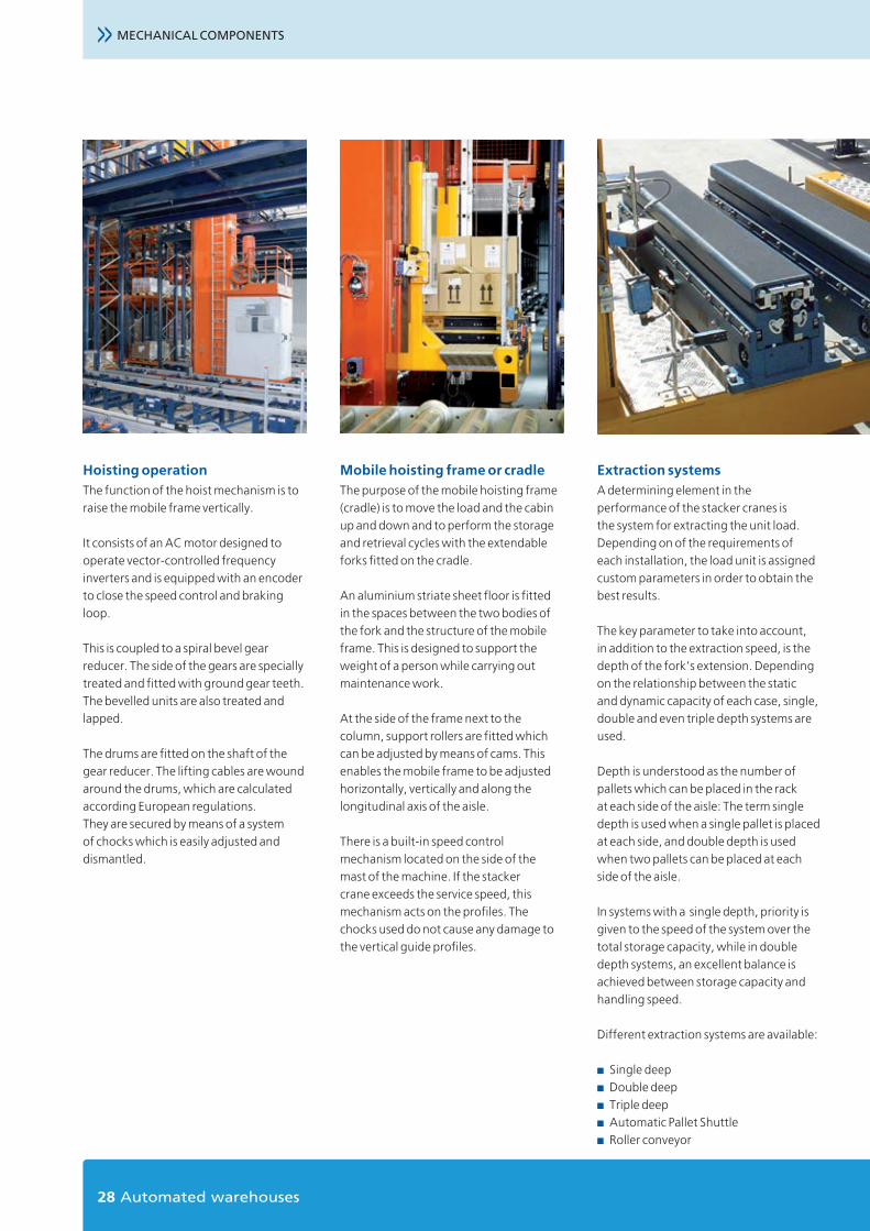
Hoisting operationThe function of the hoist mechanism is to raise the mobile frame vertically.
It consists of an AC motor designed to operate vector-controlled frequency inverters and is equipped with an encoder to close the speed control and braking loop.
This is coupled to a spiral bevel gear reducer. The side of the gears are specially treated and fitted with ground gear teeth. The bevelled units are also treated and lapped.
The drums are fitted on the shaft of the gear reducer. The lifting cables are wound around the drums, which are calculated according European regulations. They are secured by means of a system of chocks which is easily adjusted and dismantled.
Mobile hoisting frame or cradleThe purpose of the mobile hoisting frame (cradle) is to move the load and the cabin up and down and to perform the storage and retrieval cycles with the extendable forks fitted on the cradle.
An aluminium striate sheet floor is fitted in the spaces between the two bodies of the fork and the structure of the mobile frame. This is designed to support the weight of a person while carrying out maintenance work.
At the side of the frame next to the column, support rollers are fitted which can be adjusted by means of cams. This enables the mobile frame to be adjusted horizontally, vertically and along the longitudinal axis of the aisle.
There is a built-in speed control mechanism located on the side of the mast of the machine. If the stacker crane exceeds the service speed, this mechanism acts on the profiles. The chocks used do not cause any damage to the vertical guide profiles.
Extraction systemsA determining element in the performance of the stacker cranes is the system for extracting the unit load. Depending on of the requirements of each installation, the load unit is assigned custom parameters in order to obtain the best results.
The key parameter to take into account, in addition to the extraction speed, is the depth of the fork’s extension. Depending on the relationship between the static and dynamic capacity of each case, single, double and even triple depth systems are used.
Depth is understood as the number of pallets which can be placed in the rack at each side of the aisle: The term single depth is used when a single pallet is placed at each side, and double depth is used when two pallets can be placed at each side of the aisle.
In systems with a single depth, priority is given to the speed of the system over the total storage capacity, while in double depth systems, an excellent balance is achieved between storage capacity and handling speed.
Different extraction systems are available:
■ Single deep■ Double deep■ Triple deep■ Automatic Pallet Shuttle■ Roller conveyor

29www.mecalux.cz
Single-deep telescopic fork
This horizontal handling mechanism enables load units to be deposited in or extracted from single-deep racking.
The telescopic fork is made up of two arms, joined by an articulated drive shaft and driven by a motor, which guarantees that both arms move uniformly.
The arms are made of high-quality steel, to ensure the system is robust.
Triple-deep telescopic fork
This enables the placement of three pallets across each side of the aisle on shelves which have “top hat” pallet supports.
These forks are specially indicated for applications which favour increased storage density. The transport systems using headers varies slightly, due to the fact that pallets are warehoused and transported in the opposite direction than normal.
Stac
ker C
rane
s fo
r Pal
lets
Double-deep telescopic fork
This consists of a horizontal handling mechanism which helps to deposit or extract load units in double-deep racking by means of telescopic forks.
The double-deep telescopic fork is made up of the same elements as its single-deep counterpart. The difference is that it is driven by two motors.
CHARACTERISTICS SINGLE-DEEP DOUBLE-DEEP
Fork sizes for loads of 1,000 kg
Fork sizes for loads of 1,500 kg
Fork stroke
Height x width of the fork
Maximum deployment speed with load
Maximum deployment speed without load
Acceleration with/without load
Height difference between 1st and 2nd depth
Pallet support shelf location (top hat)
1,300 mm
1,300 mm
1,425 + 75 mm
70 x 175 mm
30 m/min
60 m/min
0.4 m/s2 – 0,8 m/s2
–
–
1,300 mm
1,400 mm
2,825 + 25 mm
75 x 185 mm
42 m/min
90 m/min
0.5 m/s2 – 2 m/s2
150 mm
–
TRIPLE-DEEP*
1,900 mm
–
1,435 + 50 mm
75 x 175 mm
40 m/min
80 m/min
0.8 m/s2 –1.2 m/s2
0 mm
270 mm
*Check with technical office
>>
30 Automated warehouses
MECHANICAL COMPONENTS
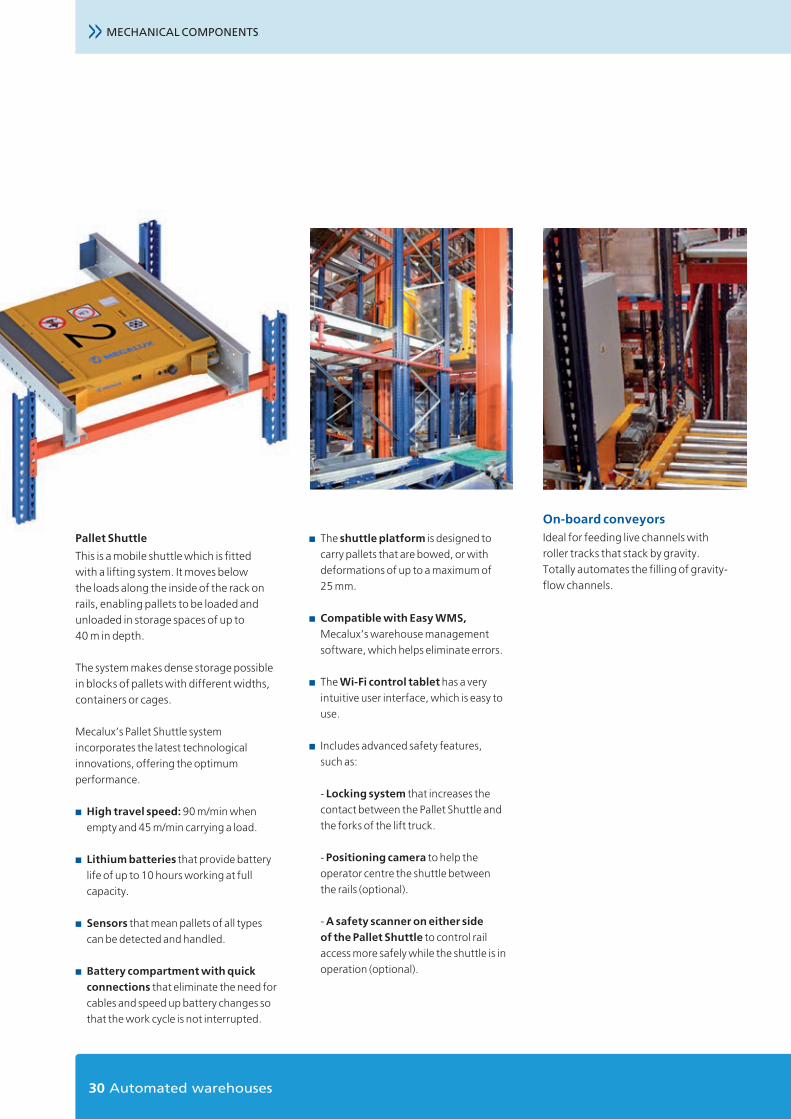
Pallet Shuttle
This is a mobile shuttle which is fitted with a lifting system. It moves below the loads along the inside of the rack on rails, enabling pallets to be loaded and unloaded in storage spaces of up to 40 m in depth.
The system makes dense storage possible in blocks of pallets with different widths, containers or cages.
Mecalux’s Pallet Shuttle system incorporates the latest technological innovations, offering the optimum performance.
■ High travel speed: 90 m/min when empty and 45 m/min carrying a load.
■ Lithium batteries that provide battery life of up to 10 hours working at full capacity.
■ Sensors that mean pallets of all types can be detected and handled.
■ Battery compartment with quick connections that eliminate the need for cables and speed up battery changes so that the work cycle is not interrupted.
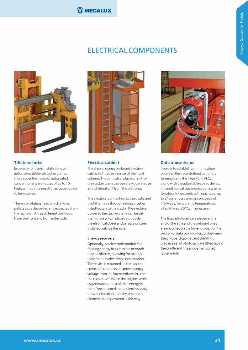
On-board conveyors Ideal for feeding live channels with roller tracks that stack by gravity. Totally automates the filling of gravity-flow channels.
■ The shuttle platform is designed to carry pallets that are bowed, or with deformations of up to a maximum of 25 mm.
■ Compatible with Easy WMS, Mecalux’s warehouse management software, which helps eliminate errors.
■ The Wi-Fi control tablet has a very intuitive user interface, which is easy to use.
■ Includes advanced safety features, such as:
- Locking system that increases the contact between the Pallet Shuttle and the forks of the lift truck.
- Positioning camera to help the operator centre the shuttle between the rails (optional).
- A safety scanner on either side of the Pallet Shuttle to control rail access more safely while the shuttle is in operation (optional).
31www.mecalux.cz
ELECTRICAL COMPONENTS Stac
ker C
rane
s fo
r Pal
lets
Trilateral forksEspecially for use in installations with automated trilateral stacker cranes, these cover the needs of automated conventional warehouses of up to 15 m high, without the need for an upper guide to be installed.
There is a rotating head which allows pallets to be deposited and extracted from the racking in three different positions: From the front and from either side.
Electrical cabinetThe stacker cranes on-board electrical cabinet is fitted in the rear of the front column. The controls are laid out so that the stacker crane can be safely operated as an individual unit from the platform.
The electrical connection to the cradle and the lift is made through sliding brushes fitted loosely to the cradle.The electrical power to the stacker crane can be cut thanks to a switch placed alongside the electrical closet and safety switches installed outside the aisle.
Energy recovery
Optionally, an electronic module for feeding energy back into the network may be offered, allowing for savings to be made in electricity consumption. The device is mounted on the stacker crane and connects the power supply voltage from the intermediate circuit of the convertors. When the engines work as generators, most of their energy is therefore returned to the client’s supply network for absorption by any other element that is powered in this way.
Data transmissionIn order to establish communication between the decentralised periphery terminals and the fixed PC or PLC, along with the adjustable-speed drives, infrared optical communication systems (photocells) are used, with reaches of up to 240 m and a transmission speed of 1.5 Mbps, for working temperatures of as little as -30 ºC, if necessary.
The fixed photocells are placed at the end of the aisle and the onboard ones are mounted on the lower guide. For the version of data communication between the on-board cabinet and the lifting cradle, a set of photocells are fitted facing the cradle and the above mentioned lower guide.

32 Automated warehouses
The aisle equipment is made up of a bottom rail, a top guide rail, safety equipment, electrical supply, data transmission and systems for measuring position.
The bottom guide railA RN-45 rail or equivalent is fastened to the concrete slab with support plates having anti-vibration plastic insulators placed at a distance that is suited to the total mass, in order to properly distribute loads.
This fastening system is quickly and easily levelled, tolerating live loads and the effects due to thermal variations.
A special welding method is used between different sections to bear the aforementioned circumstances.
The top guide rail The top guide rails is formed of either a HEA 120 profile or a structural tube. It is fixed to the rack’s profiles by means of welded adjustment plates.
Contrast wheels apply lateral force to the top guide track. It is during the depositing and extracting of goods that the forces are at their greatest.
AISLE EQUIPMENT
33www.mecalux.cz
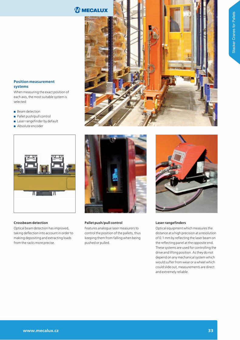
Position measurement systemsWhen measuring the exact position of each axis, the most suitable system is selected:
■ Beam detection■ Pallet push/pull control■ Laser rangefinder by default■ Absolute encoder
Laser rangefinders
Optical equipment which measures the distance at a high precision at a resolution of 0.1 mm by reflecting the laser beam on the reflecting panel at the opposite end. These systems are used for controlling the drive and lifting position. As they do not depend on any mechanical system which would suffer from wear or a wheel which could slide out, measurements are direct and extremely reliable.
Crossbeam detection
Optical beam detection has improved, taking deflection into account in order to making depositing and extracting loads from the racks more precise.
Pallet push/pull control
Features analogue laser measurers to control the position of the pallets, thus keeping them from falling when being pushed or pulled.
Stac
ker C
rane
s fo
r Pal
lets

>>
34 Automated warehouses
AISLE EQUIPMENT
Absolute encoders
Rotary devices with a codified value which is neither repetitive nor incremental, these produce an absolute and unique value for each angle of the shaft. They store the measured value even when the machine has been disconnected. They are commonly installed in telescopic forks and shuttle cars, and are fitted with coupling devices without excessive sliding or wear and, in most cases, cover short routes.
Electrical safety devices are engaged when stopping the stacker crane in order to access the aisles.

35www.mecalux.cz
Curved tracks
In this system, it is the stacker crane which carries out the manoeuvre of changing from one aisle to another by means of a railway-type switch. A simple mechanical operation by switching points enables the destination aisle to be selected.
The main difference of these stacker cranes to normal ones is the inclusion of rotating wheels with side guide rollers, which are fitted in a special console.
The curved track switches system allows the stacker cranes to move at high speeds around these bends.
The top guide fitted around bends and switches, consists of a rail designed so that the top contrast wheels of the stacker crane never leave the profile as they travel along.
Transfer bridge
A transfer bridge is a machine to move stacker cranes from one aisle to another. The stacker crane moves onto the bridge, where it is anchored and is moved sideways to the destination aisle where the transfer is to take place.
This system enables work to be done at a higher speed inside the aisles, although it is less flexible in terms of changing aisles than the curved track system.
The installation of one system or another requires an exhaustive study of the factors involved in each case.
Systems for changing aislesWhen the required rotation of stored goods is relatively low, but the storage capacity must be high, it is not necessary for a stacker crane to be installed in every aisle. In these cases, a system is put in place to allow the stacker crane to move from one aisle to another.
■ Curved tracks■ Transfer bridge
Stac
ker C
rane
s fo
r Pal
lets
36 Automated warehouses
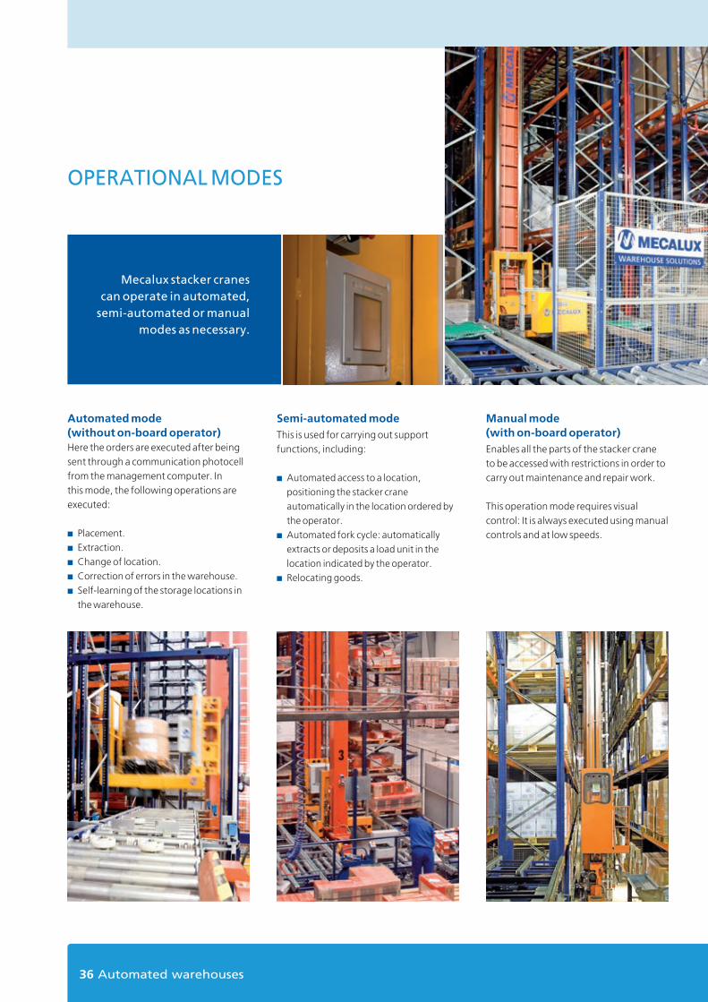
OPERATIONAL MODES
Manual mode (with on-board operator)Enables all the parts of the stacker crane to be accessed with restrictions in order to carry out maintenance and repair work.
This operation mode requires visual control: It is always executed using manual controls and at low speeds.
Automated mode (without on-board operator)Here the orders are executed after being sent through a communication photocell from the management computer. In this mode, the following operations are executed:
■ Placement.■ Extraction.■ Change of location.■ Correction of errors in the warehouse.■ Self-learning of the storage locations in
the warehouse.
Semi-automated modeThis is used for carrying out support functions, including:
■ Automated access to a location, positioning the stacker crane automatically in the location ordered by the operator.
■ Automated fork cycle: automatically extracts or deposits a load unit in the location indicated by the operator.
■ Relocating goods.
Mecalux stacker cranes can operate in automated,
semi-automated or manual modes as necessary.
37www.mecalux.cz
SAFETY EQUIPMENT
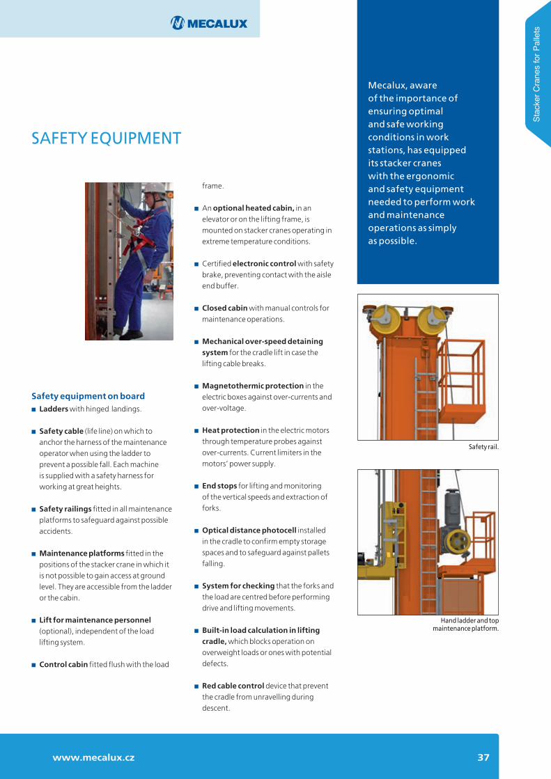
Safety equipment on board■ Ladders with hinged landings.
■ Safety cable (life line) on which to anchor the harness of the maintenance operator when using the ladder to prevent a possible fall. Each machine is supplied with a safety harness for working at great heights.
■ Safety railings fitted in all maintenance platforms to safeguard against possible accidents.
■ Maintenance platforms fitted in the positions of the stacker crane in which it is not possible to gain access at ground level. They are accessible from the ladder or the cabin.
■ Lift for maintenance personnel (optional), independent of the load lifting system.
■ Control cabin fitted flush with the load
Hand ladder and top maintenance platform.
Safety rail.
Mecalux, aware of the importance of ensuring optimaland safe working conditions in work stations, has equipped its stacker cranes with the ergonomicand safety equipment needed to perform workand maintenance operations as simply as possible.
Stac
ker C
rane
s fo
r Pal
lets
frame.
■ An optional heated cabin, in an elevator or on the lifting frame, is mounted on stacker cranes operating in extreme temperature conditions.
■ Certified electronic control with safety brake, preventing contact with the aisle end buffer.
■ Closed cabin with manual controls for maintenance operations.
■ Mechanical over-speed detaining system for the cradle lift in case the lifting cable breaks.
■ Magnetothermic protection in the electric boxes against over-currents and over-voltage.
■ Heat protection in the electric motors through temperature probes against over-currents. Current limiters in the motors’ power supply.
■ End stops for lifting and monitoring of the vertical speeds and extraction of forks.
■ Optical distance photocell installed in the cradle to confirm empty storage spaces and to safeguard against pallets falling.
■ System for checking that the forks and the load are centred before performing drive and lifting movements.
■ Built-in load calculation in lifting cradle, which blocks operation on overweight loads or ones with potential defects.
■ Red cable control device that prevent the cradle from unravelling during descent.
38 Automated warehouses
13
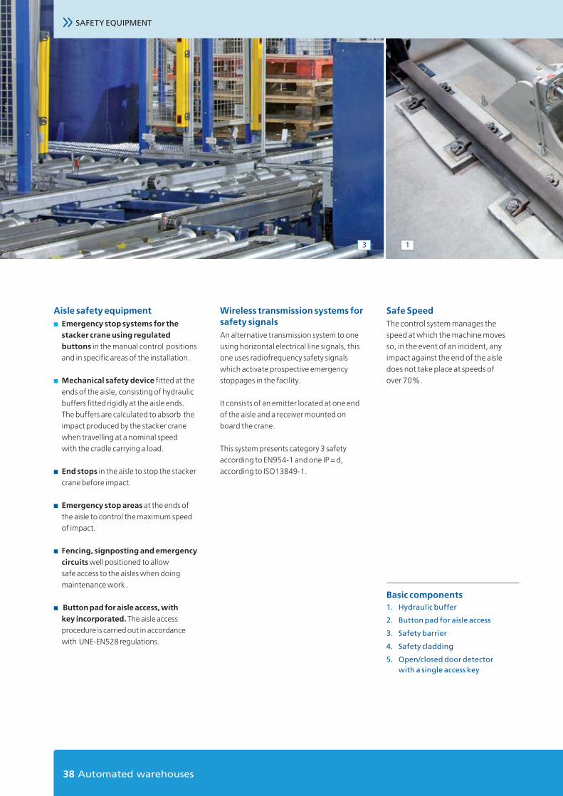
Aisle safety equipment■ Emergency stop systems for the
stacker crane using regulated buttons in the manual control positions and in specific areas of the installation.
■ Mechanical safety device fitted at the ends of the aisle, consisting of hydraulic buffers fitted rigidly at the aisle ends. The buffers are calculated to absorb the impact produced by the stacker crane when travelling at a nominal speed with the cradle carrying a load.
■ End stops in the aisle to stop the stacker crane before impact.
■ Emergency stop areas at the ends of the aisle to control the maximum speed of impact.
■ Fencing, signposting and emergency circuits well positioned to allow safe access to the aisles when doing maintenance work .
■ Button pad for aisle access, with key incorporated. The aisle access procedure is carried out in accordance with UNE-EN528 regulations.
Wireless transmission systems for safety signals An alternative transmission system to one using horizontal electrical line signals, this one uses radiofrequency safety signals which activate prospective emergency stoppages in the facility.
It consists of an emitter located at one end of the aisle and a receiver mounted on board the crane.
This system presents category 3 safety according to EN954-1 and one IP = d, according to ISO13849-1.
Safe SpeedThe control system manages the speed at which the machine moves so, in the event of an incident, any impact against the end of the aisle does not take place at speeds of over 70%.
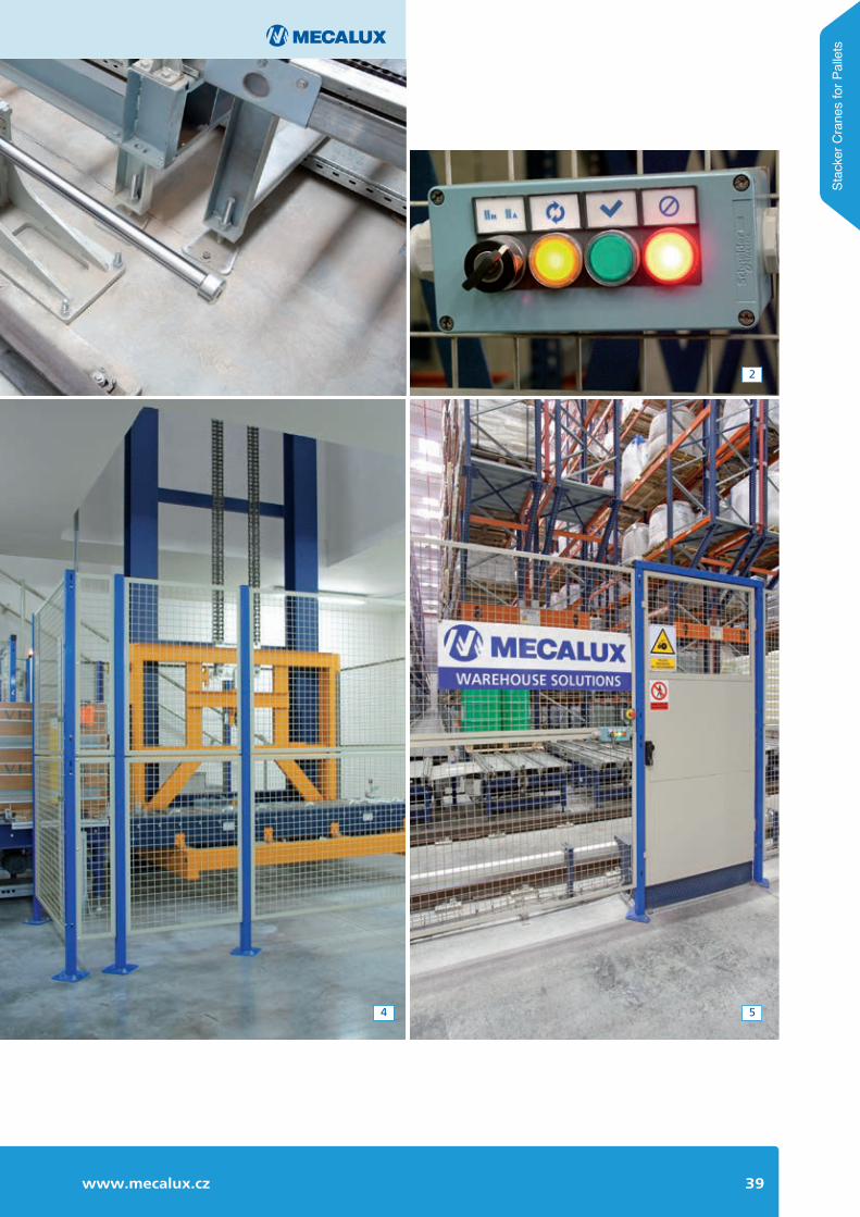
Basic components1. Hydraulic buffer
2. Button pad for aisle access
3. Safety barrier
4. Safety cladding
5. Open/closed door detector with a single access key
>> SAFETY EQUIPMENT
39www.mecalux.cz
4
2
5
Stac
ker C
rane
s fo
r Pal
lets

For more information visit our website: www.mecalux.czor contact email: [email protected]
Zastoupení: Argentina - Belgie - Brazílie - Česko - Chile - Francie - Itálie - Kanada - Kolumbie - Mexiko - NěmeckoNizozemí - Peru - Polsko - Portugalsko - Slovensko - Španělsko - Spojené Království - Turecko - Uruguay - USA
Mecalux má zastoupení ve více než 70 zemích celého světa
MECALUX ČESKÁ REPUBLIKA, S.R.O.
PRAHAtel.: (+420) 222 524 240
Jankovcova 1595/14 - 170 00 Praha 7fax: (+420) 222 516 388