stability and dynamic performance improvement of a
TRANSCRIPT

University of Nebraska - LincolnDigitalCommons@University of Nebraska - LincolnFaculty Publications from the Department ofElectrical and Computer Engineering Electrical & Computer Engineering, Department of
2013
Stability and Dynamic Performance Improvementof a Sensorless IPMSM Drive via AdaptiveEstimated-Speed- Assisted Position Prediction andCurrent Quality EvaluationYue ZhaoUniversity of Nebraska-Lincoln, [email protected]
Wei QiaoUniversity of Nebraska–Lincoln, [email protected]
Long WuJohn Deere Electronic Solutions, [email protected]
Follow this and additional works at: http://digitalcommons.unl.edu/electricalengineeringfacpub
Part of the Computer Engineering Commons, and the Electrical and Computer EngineeringCommons
This Article is brought to you for free and open access by the Electrical & Computer Engineering, Department of at DigitalCommons@University ofNebraska - Lincoln. It has been accepted for inclusion in Faculty Publications from the Department of Electrical and Computer Engineering by anauthorized administrator of DigitalCommons@University of Nebraska - Lincoln.
Zhao, Yue; Qiao, Wei; and Wu, Long, "Stability and Dynamic Performance Improvement of a Sensorless IPMSM Drive via AdaptiveEstimated-Speed- Assisted Position Prediction and Current Quality Evaluation" (2013). Faculty Publications from the Department ofElectrical and Computer Engineering. 342.http://digitalcommons.unl.edu/electricalengineeringfacpub/342
Stability and Dynamic Performance Improvement of a Sensorless IPMSM Drive via Adaptive Estimated-Speed-
Assisted Position Prediction and Current Quality Evaluation
Yue Zhao Power & Energy Systems Laboratory Department of Electrical Engineering
University of Nebraska-Lincoln Lincoln, NE 68588-0511 USA
Wei Qiao
Power & Energy Systems Laboratory Department of Electrical Engineering
University of Nebraska-Lincoln Lincoln, NE 68588-0511 USA
Long Wu
John Deere Electronic Solutions 4101 19th Avenue North Fargo, ND 58102 USA
Abstract—This paper studies stability issues of sensorless torque control of high power interior permanent magnet synchronous machines (IPMSMs) under large load transients, e.g., complete torque reversals with the highest slew rate allowed. To perform a sensorless vector control, a current model-based sliding-mode observer is utilized to estimate the rotor position. The correlation between current regulation quality and position estimation accuracy is theoretically studied and experimentally verified. Based on the correlation, the accuracy of position estimation can be evaluated online indirectly. Moreover, an adaptive estimated-speed-assisted position prediction (ESAPP) scheme is proposed to improve the stability and performance of the sensorless control systems under large load transients. The ESAPP period is adapted according to the position estimation accuracy. Experimental results on a 150 kW sensorless IPMSM drive system are provided to validate the proposed algorithms.
Index Terms—Current regulation; interior permanent magent synchronous machine (IPMSM); position estimation; sensorless control; sliding-mode observer (SMO); system stability
I. INTRODUCTION During the last two decades, various rotor position
observation schemes have been investigated for sensorless IPMSM drive systems. For medium- and high-speed applications, model-based (e.g., extended electromotive force (EEMF) model [1]) position estimation schemes have been widely investigated due to their advantages of standard design procedure and easy implementation. In these schemes, the rotor position information can be calculated online according to the IPMSM model and sensed current/voltage. The most critical issue in the sensorless drives, especially for vehicle applications, is the system stability. The stability analysis of a sensorless drive can be performed via rigorous control theories [2]. However, due to the modeling inaccuracy caused by parametric uncertainties (e.g., machine parameters variations) and unmodeled dynamics (e.g., nonlinear effect of the inverter), the stability criteria can
rarely be given analytically and explicitly. Therefore, it is often difficult to perform a closed-loop stability analysis to design a rotor position observer offline for sensorless IPMSM drive systems, and further online parameter tuning is normally required to ensure the performance of the observer. For the EEMF-based position observation methods, the states of interest in the plant model, e.g., the magnitudes of the EEMF components, are dependent on load and the change of currents. When an abrupt load change occurs, the EEMF components and their estimated values will have large variations and distortions. In addition, in commercial drive systems, the adoption of over-modulation strategies, protective derating features and current/voltage/speed/torque slew rate limiters will introduce more nonlinear effects and unmodeled dynamics. Therefore, significant research effort is still needed to improve the stability and dynamic performance of sensorless drive systems under large load transients.
Fig. 1 shows a typical output torque profile of an IPMSM operating as a generator on a hybrid electric vehicle during one driving cycle. During this driving cycle, abrupt torque changes are the most challenging issue to the stability of the sensorless drive system. As shown in the subfigure of Fig. 1, the output torque increases approximately 300 Nm within 10 ms. This means that the torque slew rate is around 30000 Nm/s. Due to the abrupt torque changes, the machine currents are highly distorted and it is difficult for a model-based observer to accurately estimate the EEMF and the rotor position. However, under this circumstance, the sensorless drive system is still required to have both stable operation and satisfactory dynamic performance.
In the literature, several EEMF model-based position observers, such as disturbance observers [1], [3] and sliding-mode observers (SMOs) [4], [5], have been proposed for sensorless control of IPMSMs in the medium- and high-speed range. To obtain a smooth EEMF estimation, low-pass filters (LPF) are always utilized in those methods. When the drive system is being operated in stable loading conditions,
This work was supported in part by Deere & Company and the U.S. National Science Foundation under grant ECCS-0901218.
3473978-1-4799-0336-8/13/$31.00 ©2013 IEEE

LPFs can effectively filter out the noise, and then accurate rotor position information can be obtained from the filtered estimated EEMF components. When an abrupt load change occurs, the phase currents and EEMF components will have large distortions and heavy harmonics. Under this circumstance, LPFs will filter out not only the noise but also the useful information in the estimated EEMF components. This will result in a large position estimation error or even system instability [6] during the transient stage.
Fig. 1. A typical output torque profile of an IPMSM operating as a generator
on a hybrid electric vehicle during one driving cycle.
To meet the requirements in real-world applications, this paper proposes an adaptive estimated-speed-assisted position prediction (ESAPP) scheme and a current quality evaluation scheme to ensure satisfactory dynamic performance and stability of IPMSM sensorless drive systems. In this paper, a current model-based SMO is utilized to estimate the rotor position. Since the observer is designed based on the current model and using sensed phase currents of the IPMSM, the correlation between current tracking error and position estimation error is established and experimentally validated in this paper. Based on the correlation, the accuracy of the position estimation can be evaluated online indirectly. Moreover, by using the estimated speed, the rotor position information can also be predicted. Based on the predicted rotor position, an ESAPP scheme is proposed and is applied to the sensorless control system to ensure its stability during large load transients. The period of applying the ESAPP
scheme is adapted according to the position estimation quality. The effectiveness of the proposed method during large load transients, including 20000 Nm/s complete torque reversal, is validated on a 150 kW sensorless IPMSM drive used in heavy-duty, off-road, hybrid electric vehicles.
II. AN ADAPTIVE SLIDING-MODE OBSERVER-BASED POSITION ESTIMATOR
In this paper, a model-based rotor position estimator [7] is utilized. The core of the position estimator is an EEMF-model based discrete-time SMO (DSMO), which is designed to estimate the EEMF components of an IPMSM. To utilize digital controllers in the IPMSM drive system, the DSMO is designed as:
*
*
[ 1] [ ] [ ] [ ]
[ 1] [ ] [ ] [ ]
ˆ ˆ1
ˆ ˆ1
q d ss re
d d d
q d ss re
d d d
k k k k
k k k k
L Lv T Ri T i lZ i
L L L
L Lv T Ri T i lZ i
L L L
αα β α α
ββ α β β
ω
ω
+
+
⎧ −⎛ ⎞ ⎛ ⎞= + + + −⎪ ⎜ ⎟ ⎜ ⎟⎜ ⎟⎪ ⎝ ⎠⎝ ⎠
⎨⎛ ⎞− ⎛ ⎞⎪ = − − + −⎜ ⎟ ⎜ ⎟⎪ ⎜ ⎟ ⎝ ⎠⎝ ⎠⎩
(1)
where Ts is the sampling period of the DSMO and current controllers; R is the stator resistance; Ld and Lq are the d-axis and q-axis inductances, respectively; v*
α and v*β are the
voltage commands in the stationary reference frame generated by the current controllers; l is the observer gain; Zα [k] and Zβ [k] are the outputs of saturation functions at the kth time step, which contain the estimated EEMF components if the sliding mode is enforced. Since Zαβ = [Zα, Zβ]T are switching signals and contain many harmonics, two second-order LPFs are utilized to extract the estimated EEMF components. A phase delay introduced by the LPFs in the estimated EEMF is compensated by a phase compensator. Moreover, two adaptive schemes [7] are designed to guarantee good position estimation performance of the DSMO over a wide load (speed and/or torque) range. In the first scheme, the saturation limit of the saturation function is adapted to the load condition to ensure good tracking performance and fast dynamic response of the DSMO. In the second scheme, the parameters of the LPFs are adapted according to the estimated speed. By using the two adaptive
Fig. 2. The overall block diagram of the DSMO-based position estimator.
*di
di
qi
*qi
pd idk k s+
pq iqk k s+
ˆre qLωqi
ˆre dLωˆre mω λ
di
αβdq
Equ. (1) α-Loop
Equ. (1)β-Loop
iα
iβ
iβ
iα αε
βε
*vα*vβ
Zα
Zβ
l
l
reθ
2 22 c c
as sω ω+ +
2 22 c c
as sω ω+ +
1tan−
12 2
ˆ2tan
ˆre c
c re
ω ωω ω
− ⎛ ⎞⎜ ⎟⎜ ⎟−⎝ ⎠
reθ
SMOPosition
Estimator
θθΔ
Accuracy Evaluation
diΔ
qiΔ
*dv*qv
Current Controller
3474

schemes, the steady-state error (i.e., Δθ = θ − ) of the estimated position ( ) with respect to the measured position (θ) from a resolver is limited within ±3 electric degrees over a wide load range of the IPMSM. The overall block diagram of the position estimator is shown in Fig. 2.
III. POSITION ESTIMATION ACCURACY EVALUATION VIA CURRENT QUALITY EVALUATION
A. Correlation between Current Regulation Quality and Position Estimation Quality In a sensorless drive system, it is desired to know the
accuracy of position estimation, namely, whether the position estimation error Δθ is limited within an acceptable range or not, during all operating conditions. However, the information of the actual rotor position is unknown in the sensorless drive system. Therefore, it is impossible to evaluate the position estimation accuracy directly; and an online indirect position estimation accuracy evaluation scheme is needed.
According to the principle of orthogonality [8] for an optimal filter/observer, the estimation error and the input data samples are orthogonal (uncorrelated), i.e.,
0E ( ) ( ) 0e n x n =⎡ ⎤⎣ ⎦ (2)
where E[·] denotes statistical expectation, e0(n) is the estimation error when the observer parameters are set at their optimal values and x(n) is the input data of the observer. Equation (2) indicates that the estimation error is uncorrelated with the input of the observer. The principle of orthogonality is well applicable to the system in certain ideal conditions, e.g., when the additive noise in the input data is white or uncorrelated with the input data. However, when the additive noise is nonwhite or has a certain correlation with the input data, the estimation error will have a correlation with the additive noise as well. In this work, due to the use of digital controllers, both the imperfect current regulation and discrete-time current sensing could introduce nonwhite additive noise to the input of the observer.
This paper proposes to evaluate the position estimation accuracy indirectly via evaluating the current regulation quality, because they are highly correlated. The relationships between the current tracking errors, Δid and Δiq shown in Fig. 2, and the position estimation error (Δθ) are derived in the d-q rotating reference frame with the assumption that the inverter is ideal, i.e., the voltage references, v*
d and v*q,
generated by the current-regulated vector control scheme, are equal to the machine terminal voltages. By assuming v*
d = vd and v*
q = vq, the following can be obtained.
( )( )( ) ( )( ) ( )
*
*
ˆ
ˆ =
=
d pd id d re q q d
d d re q q
q pq id q re d d m q
q q re d d m
v k k s i L i v
R pL i L i
v k k s i L i v
R pL i L i
ω
ω
ω λ
ω λ
⎧ = + Δ − =⎪⎪ = + −⎪⎨
= + Δ + +⎪⎪
+ + +⎪⎩
(3)
The proportional-integral (PI) gains, kpd, kid, kpq, and kiq, are selected by using the zero-pole cancellation technique, and their values are: ωbLd, ωbR, ωbLq, and ωbR, respectively, where ωb is the bandwidth of the current controllers. Rearrange (3) by considering and ωre = sθ,
*
*d d d d
q q q q
H i N i
H i N i
θθ
⎧Δ = Δ +⎪⎨
Δ = Δ +⎪⎩ (4)
where the transfer matrix are:
( ) ( )
( )( )( ) ( )
2
2
=
b d d
q qq qd d
q q b q d
m d dm d d
s R sL R sLsL is L iH N
H N s R sL R sLs L is L i
ω
ωλλ
⎡ ⎤+ + +−⎢ ⎥⎢ ⎥⎡ ⎤⎢ ⎥⎢ ⎥
+ +⎢ ⎥⎣ ⎦ +⎢ ⎥++⎢ ⎥⎣ ⎦
According to (4), the relationships between Δθ and Δid, and between Δθ and Δiq, can be described in a linear form. This result theoretically verifies that the current tracking errors and the position estimation error are correlated. According to the probability theory, correlation coefficients are often utilized to describe the degree of similarity between two signals. The correlation coefficient between two variables, X and Y, is defined as φ(X, Y) = γ(X, Y)/(σXσY), where γ(X, Y) is the covariance between X and Y, and σX and σY are the standard deviations of X and Y, respectively. Therefore, if the standard deviations, σΔθ, σΔid, and σΔiq, are known, the correlation coefficients, φ(Δθ, Δid) and φ(Δθ, Δiq), can be obtained.
In addition to the theoretical analysis, the correlations between the current tracking errors and Δθ are experimentally verified on a 150 kW sensorless IPMSM drive system. The parameters of the test IPMSM are listed in Table I. Fig. 3 shows the response of Δθ with respect to those of Δid and Δiq, when a 33% step change is applied to the torque at 0 s. In this experiment, the bandwidth of the current controllers is intentionally increased to get a poor current regulation quality at steady state. The results show that the estimated rotor position has larger oscillating errors during current transients. When the currents settle down at 40 ms, the position estimation error oscillates symmetrically around zero, and the magnitude of oscillation is limited within a small range of ±4 electric degrees.
TABLE I. SPECIFICATIONS OF THE IPMSM
Maximum power 150 kW Stator resistance 0.01 Ω
Maximum torque 300 Nm Base speed 5000 RPM
Flux linkage 0.095 Wb Pole-pair number 4
Average Ld 0.2 mH Average Lq 0.55 mH
Based on numerous data of Δid, Δiq and Δθ measured from the test system under all loading conditions, the results of the statistical analysis show that φ(Δθ, Δid) is close to 1,
3475

which indicates a strong positive correlation between Δθ and Δid; while φ(Δθ, Δiq) is close to −1, which indicates a strong negative correlation between Δθ and Δiq. The opposite signs of φ(Δθ, Δid) and φ(Δθ, Δiq) coincide with the fact that the signs of Hd and Hq in (3) are opposite. Moreover, for the IPMSM and control software used in this paper, |φ(Δθ, Δid)| is larger than |φ(Δθ, Δiq)|, which indicates a stronger correlation between Δθ and Δid. Therefore, the quality of id regulation is a good candidate to evaluate the accuracy of position estimation.
(a)
(b)
Fig. 3. Response of Δθ with respect to those of (a) Δid and (b) Δiq.
B. Current Regulation Quality Evaluation Criterion This section proposes a criterion for current regulation
quality evaluation (CRQE). Firstly, a current error margin is defined as a constant percentage, e.g., 20%, of i*
d. This percentage is selected based on the tracking performance of the current controller, which is related to the PI gains, control loop frequency and other control related factors.. Secondly, as shown in Fig. 3, since Δid oscillates, there are zero-crossing points in Δid. Therefore, the current regulation quality cannot be evaluated based on the value of Δid at a single sampling point. In this work, the current regulation quality is evaluated according to the values of Δid at multiple consecutive sampling points. Generally speaking, if the rotor speed of an IPMSM is ω in rad/s and the sampling frequency of the current controller is fs in Hz, there are 2πfs/(poω) samples in one electric revolution, where po is the number of pole pairs. Moreover, there is at least one peak of the current tracking error in half electric revolution. Therefore, πfs/(poω) consecutive samples of Δid are used together to evaluate current regulation quality.
The CRQE criterion is described as follows: If the values of |Δid| at all consecutive πfs/(poω) samples are always
smaller than the current error margin, the current regulation quality is regarded as good. Otherwise, the current regulation quality is poor. Based on the definition of the CRQE criterion, the results of the statistical analysis on the relationship between current regulation quality and position estimation accuracy are shown in Fig. 4. Fig. 4(a) is a table of the conditional probability that the position estimation error is limited within a certain range in electric degrees (the column index), given that the current regulation quality is good when a certain number of consecutive samples of |Δid| (the row index) are evaluated together. A larger row index indicates that the corresponding CRQE criterion is stricter. Fig. 4(a) statistically verifies that by choosing an appropriate number of consecutive current samples for CRQE, the current regulation quality can be an exact indicator of the position estimation error, namely, their correlation is one. Fig. 4(b) is the corresponding probability distribution profile. An obvious finding from Fig. 4 is that the position estimation error is always limited within 6°, if the current regulation quality is good in consecutive 15 or 20 samples.
(a)
(b)
Fig. 4. Results of statistical analysis on the relationship between current regulation quality and position estimation quality.
IV. ADAPTIVE ESTIMATED-SPEED-ASSISTED POSITION PREDICTION SCHEME
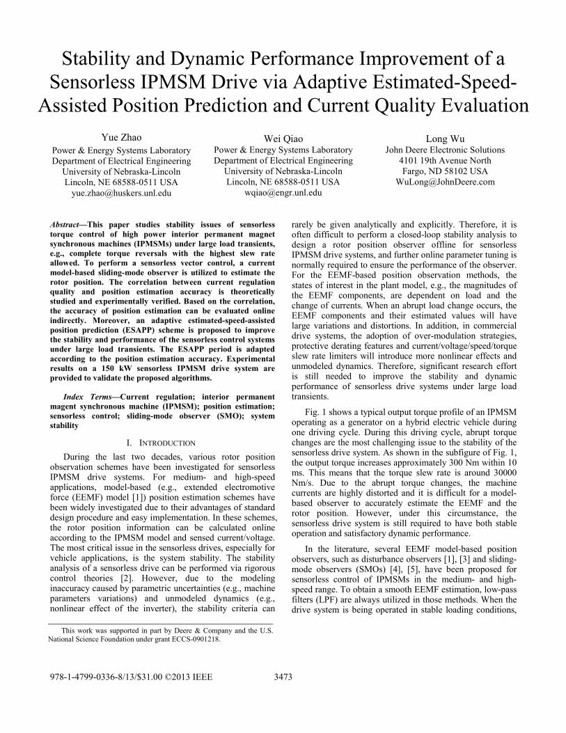
In this section, an adaptive ESAPP scheme, as illustrated in Fig. 5, is proposed to improve the dynamic performance and ensure the stability of the sensorless IPMSM drive system during large load transients. The adaptive ESAPP scheme uses the information of position estimation accuracy
diθΔ
Δ
qiθΔ
Δ
Maximum position estimation error (Elec. Deg.)
# of consecutive samples
Maximum Position Estimation
Error (Elec. Deg.)
3476
evaluation presented in section III. In Fig. 5, Xd is a binary index of id regulation quality evaluation, where 1 stands for good and 0 stands for poor; is the estimated rotor position from the DSMO-based position estimator; and θ is the rotor position predicted by using the estimated rotor speed, which in turn is obtained from the estimated rotor position. The superscript i indicates the ith PWM switching cycle. The adaptive ESAPP scheme is designed to determine a proper control angle θc for coordinate transformation in the vector control of the sensorless drive system according to the following general rules:
1) Suppose that an adaptive ESAPP period starts from the ith PWM cycle, and in this cycle, the estimated position is used as the control angle. It is assumed that the accuracy of the estimated rotor position is acceptable in the ith PWM cycle, and this assumption will be verified in Step (3).
2) In the following n−1 PWM cycles, the rotor speed predicted rotor position will be used as the control angle, which is calculated as: 1 ˆ=i k i k i k i
c c sTθ θ θ ω+ + + −= + ⋅ , where 0
< k < n and ˆ iω is the rotor speed calculated using the estimated rotor position in the ith PWM cycle. n is a fixed number determined by n/fs = 2Tmax/ΔTmax, where ΔTmax (in Nm/s) is the highest torque slew rate limit of the drive system and Tmax is the maximum torque in Nm. Therefore, the sensorless drive system is able to ride through a complete torque reversal between ±Tmax by using the speed predicted position during the fixed ESAPP period having n PWM cycles.
3) Once the fixed ESAPP period ends, the current regulation quality will be evaluated from the (i + n)th PWM cycle onwards. The speed predicted position will be continuously used as the control angle in the following
PWM cycles as long as Xd is 0. If in the (i + n + m)th PWM cycle Xd becomes 1, the control angle will be switched to the estimated position and the next adaptive ESAPP period begins. Therefore, the overall adaptive ESAPP period has n + m PWM cycles.
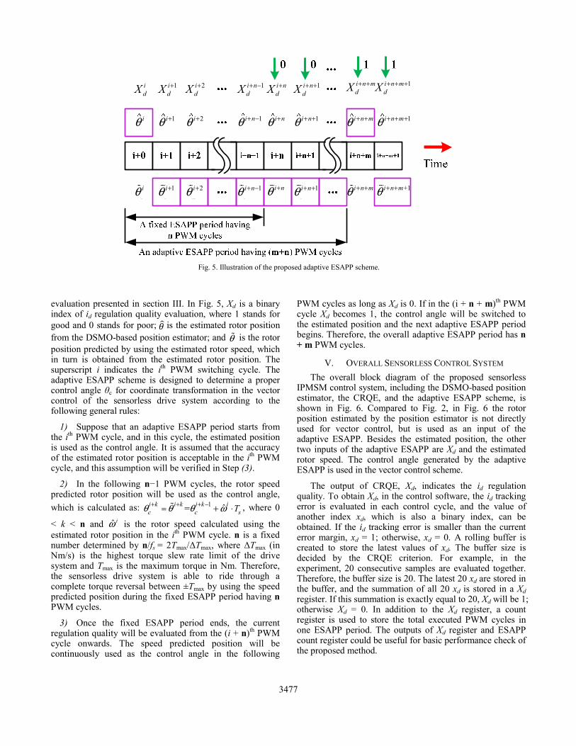
V. OVERALL SENSORLESS CONTROL SYSTEM The overall block diagram of the proposed sensorless
IPMSM control system, including the DSMO-based position estimator, the CRQE, and the adaptive ESAPP scheme, is shown in Fig. 6. Compared to Fig. 2, in Fig. 6 the rotor position estimated by the position estimator is not directly used for vector control, but is used as an input of the adaptive ESAPP. Besides the estimated position, the other two inputs of the adaptive ESAPP are Xd and the estimated rotor speed. The control angle generated by the adaptive ESAPP is used in the vector control scheme.
The output of CRQE, Xd, indicates the id regulation quality. To obtain Xd, in the control software, the id tracking error is evaluated in each control cycle, and the value of another index xd, which is also a binary index, can be obtained. If the id tracking error is smaller than the current error margin, xd = 1; otherwise, xd = 0. A rolling buffer is created to store the latest values of xd. The buffer size is decided by the CRQE criterion. For example, in the experiment, 20 consecutive samples are evaluated together. Therefore, the buffer size is 20. The latest 20 xd are stored in the buffer, and the summation of all 20 xd is stored in a Xd register. If this summation is exactly equal to 20, Xd will be 1; otherwise Xd = 0. In addition to the Xd register, a count register is used to store the total executed PWM cycles in one ESAPP period. The outputs of Xd register and ESAPP count register could be useful for basic performance check of the proposed method.
Fig. 5. Illustration of the proposed adaptive ESAPP scheme.
iPθ 1i
Pθ + 2iEθ + 1i n
Pθ + − i nPθ + 1i n
Pθ + +
iEθ 1i
Eθ + 2iEθ + 1i n
Eθ + − i nEθ + 1i n
Eθ + +
idX 1i
dX + 2idX + 1i n
dX + − i ndX + 1i n
dX + + i n mdX + +
i n mEθ + +
i n mPθ + +
1i n mdX + + +
1i n mEθ + + +
+1i n mPθ + +
3477
VI. EXPERIMENTAL RESULTS
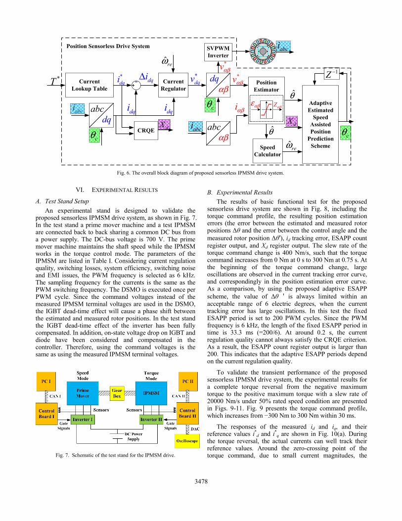
A. Test Stand Setup An experimental stand is designed to validate the
proposed sensorless IPMSM drive system, as shown in Fig. 7. In the test stand a prime mover machine and a test IPMSM are connected back to back sharing a common DC bus from a power supply. The DC-bus voltage is 700 V. The prime mover machine maintains the shaft speed while the IPMSM works in the torque control mode. The parameters of the IPMSM are listed in Table I. Considering current regulation quality, switching losses, system efficiency, switching noise and EMI issues, the PWM frequency is selected as 6 kHz. The sampling frequency for the currents is the same as the PWM switching frequency. The DSMO is executed once per PWM cycle. Since the command voltages instead of the measured IPMSM terminal voltages are used in the DSMO, the IGBT dead-time effect will cause a phase shift between the estimated and measured rotor positions. In the test stand the IGBT dead-time effect of the inverter has been fully compensated. In addition, on-state voltage drop on IGBT and diode have been considered and compensated in the controller. Therefore, using the command voltages is the same as using the measured IPMSM terminal voltages.
Fig. 7. Schematic of the test stand for the IPMSM drive.
B. Experimental Results The results of basic functional test for the proposed
sensorless drive system are shown in Fig. 8, including the torque command profile, the resulting position estimation errors (the error between the estimated and measured rotor positions Δθ and the error between the control angle and the measured rotor position Δθ '), id tracking error, ESAPP count register output, and Xd register output. The slew rate of the torque command change is 400 Nm/s, such that the torque command increases from 0 Nm at 0 s to 300 Nm at 0.75 s. At the beginning of the torque command change, large oscillations are observed in the current tracking error curve, and correspondingly in the position estimation error curve. As a comparison, by using the proposed adaptive ESAPP scheme, the value of Δθ ' is always limited within an acceptable range of 6 electric degrees, when the current tracking error has large oscillations. In this test the fixed ESAPP period is set to 200 PWM cycles. Since the PWM frequency is 6 kHz, the length of the fixed ESAPP period in time is 33.3 ms (=200/6). At around 0.2 s, the current regulation quality cannot always satisfy the CRQE criterion. As a result, the ESAPP count register output is larger than 200. This indicates that the adaptive ESAPP periods depend on the current regulation quality.
To validate the transient performance of the proposed sensorless IPMSM drive system, the experimental results for a complete torque reversal from the negative maximum torque to the positive maximum torque with a slew rate of 20000 Nm/s under 50% rated speed condition are presented in Figs. 9-11. Fig. 9 presents the torque command profile, which increases from −300 Nm to 300 Nm within 30 ms.
The responses of the measured id and iq, and their reference values i*
d and i*q are shown in Fig. 10(a). During
the torque reversal, the actual currents can well track their reference values. Around the zero-crossing point of the torque command, due to small current magnitudes, the
Fig. 6. The overall block diagram of proposed sensorless IPMSM drive system.
Current Lookup Table
Current Regulator
SVPWMInverter
αβabc
αβdq Position
Estimator
abc
*T
abci dqidq
*dqi dqiΔ *
dqv
abci
*vαβ
*vαβ
iαβ
abci
αβε Zαβcθθ
cθ CRQE dX
SpeedCalculator
θˆreω
AdaptiveEstimated
Speed Assisted Position
Prediction Scheme
cθ
1Z −
dX
ˆreω
dqi
Position Sensorless Drive System
3478

current tracking slightly slows down, causing delays of the actual current responses with respect to the current references. However, the proposed sensorless control system has successfully ridden through this period and no instability has been observed. Fig. 10(b) shows the measured three phase stator currents of the machine.
Fig. 8. Basic functional test results of the proposed sensorless IPMSM
drive system.
Fig. 9. Profile of the torque command, whose slew rate is 20,000 Nm/s
during transient.
The corresponding error between the control angle and the measured rotor position from a resolver, Δθ ' = θ − θc, is shown in Fig. 11. Fig. 11(a) is the profile of Δθ ' during
0~100 ms. Due to the inertia of the mechanical system, the rotor speed is relatively stable at the beginning of the torque change, i.e., 0~18 ms. Consequently, the control angle obtained from the proposed scheme is accurate. During 18~100 ms, due to the rotor speed oscillation, as shown in Fig. 11(c), the control angle also has relatively large oscillating errors, but the value of Δθ ' is always limited within 6 electric degrees, which is coincident with the result of the statistical analysis shown in Fig. 4. Fig. 11(b) shows the profile of Δθ ' during a longer period of 0~1.2 s, which is long enough for the speed and position errors to settle down. The steady-state position estimation error is within ±3 electric degrees when the torque is 300 Nm.
(a)
(b)
Fig. 10. Profiles of currents: (a) trajectories of the command idq and the measured idq, and (b) profiles of the measured three phase currents.
VII. CONCLUSION In this paper, the correlation between current tracking
error and position estimation error has been theoretically and experimentally studied. Based on this correlation, the current regulation quality, which has been evaluated in the sensorless drive system by using the proposed CRQE criterion, has been utilized online to evaluate the accuracy of
θΔθ ′Δ
*di
di
qi
*qi
3479

position estimation. Moreover, an adaptive ESAPP scheme has been proposed to use the information of the current regulation quality to improve the accuracy of position estimation. Experimental results on a 150 kW sensorless IPMSM drive system have validated that the proposed scheme is able to provide accurate position estimation to ensure the sensorless IPMSM drive system to achieve comparable performance with respect to the sensor-based drive system under large load transients.
(a)
(b)
(c)
Fig. 11. Profiles of Δθ': (a) 0-100 ms, and (b) 0-1200 ms; and (c) the corresponding measured and estimated speed profiles during 0-1200 ms.
REFERENCES [1] Z. Chen, M. Tomita, S. Doki, and S. Okuma, “An extended
electromotive force model for sensorless control of interior permanent-magnet synchronous motors,” IEEE Trans. Industrial Electronics, vol. 50, no. 2, pp. 288- 295, Apr. 2003.
[2] S. Pongam and S. Sangwongwanich, “Stability and dynamic performance improvement of adaptive full-order observers for sensorless PMSM drive,” IEEE Trans. Power Electronics, vol. 27, no. 2, pp. 588–600, Feb. 2012.
[3] S. Morimoto, K. Kawamoto, M. Sanada, and Y. Takeda, “Sensorless control strategy for salient-pole PMSM based on extended EMF in rotating reference frame,” IEEE Trans. Industrial Applications, vol. 38, no. 4, pp. 1054-1061, Jul./Aug. 2002.
[4] G. Foo and M. F. Rahman, “Sensorless sliding-mode MTPA control of an IPM synchronous motor drive using a sliding-mode observer and HF signal injection,” IEEE Trans. Industrial Electronics, vol. 57, no. 4, pp. 1270-1278, Apr. 2010.
[5] Y. Zhao, W. Qiao, and L. Wu, “An adaptive quasi-sliding-mode rotor position observer-based sensorless control for interior permanent magnet synchronous machines,” IEEE Trans. Power Electronics, vol. 28, no. 12, pp. 5618-5629, Dec. 2013.
[6] Y. Zhao, W. Qiao, and L. Wu, “Estimated-speed-aided stabilizers for sensorless control of interior permanent magnet synchronous machines," in Proc. IEEE Energy Conversion Congress and Exposition, Sept. 2012, pp. 2631-2638.
[7] Y. Zhao, W. Qiao, and L. Wu, “Sensorless control for IPMSMs based on a multilayer discrete-time sliding-mode observer,” in Proc. IEEE Energy Conversion Congress and Exposition, Sept. 2012, pp. 1788-1795.
[8] B. Farhang-Boroujeny, Adaptive Filters Theory and Applications, 1st Ed, Wiley, 1999.
3480