sta-kon solderless crimp connectors to terminate...
TRANSCRIPT

278
Thomas & Betts • www.tnb-europe.com
5.1
Sta-Kon®
Solder less cr imp connectors to
terminate cables

279
Thomas & Betts • www.tnb-europe.com
5.1
TERMINATION SYSTEMS
5.1 STA-KON® - CRIMP TERMINALS 278
Selection guide 282
Insulated terminals 284
Ring terminals 284
Fork terminals 287
Pin terminals & Blade terminals 290
Bootlace ferrules 292
Disconnect terminals 293
Sectional terminal block 296
Bullet disconnects 296
Butt splices 298
Wire joints 299
Non-insulated terminals 300
Ring terminals 300
Fork terminals 301
Pin terminal 302
Butt splices 302
Copper tube ring terminals 303
Disconnect terminals 305
Tabs for soldering 307
Screw mounted disconnect tabs 308
Crimping tools 310
Plier type crimping tools 310
Standard crimping tools 310
Ergonomic hand tools with interchangeable dies 312
Ergonomic hand tools with fixed die 312
Large hand tool 314
Hydraulic tools 315
Tooling and die selection chart 316
Stripping & cutting tools 317
Ergonomic hand tools 317
Standard hand tools 318
Heavy-duty cable cutters 321
5.2 COLOR-KEYED® - POWER CABLE CONNECTORS 322
5.3 DRAGON TOOTH® - MAGNET WIRE TERMINALS 336
5.4 SHIELD-KON® - SHIELDED CABLE CONNECTORS 368
280
Thomas & Betts • www.tnb-europe.com
5.1
Sta-Kon® Solder less cr imp connectors
Experience the Sta-Kon® advantage!
Thomas & Betts developed the first tool-applied solderless
terminals and connectors more than 60 years ago in
response to industry awareness of the need for better
performance of electrical systems.
Since then, the crimping technology, in which a permanent join-
ing of wires / cables to connectors is achieved by the insertion of
a conductor into the barrel of the connector, which is then com-
pressed to form a solid joint, has proven its many advantages year
after year. Reliability of connection, low installed cost, low level of
skill required to produce repeatable and quality crimps, environ-
mental compliance (versus soldering for instance) are examples of
benefits that have given this technology its natural superiority.
281
Thomas & Betts • www.tnb-europe.com
5.1
Wide range of styles,
materials and
application tools
Easy entry design
This feature makes wire insertion faster and easier. Chamfering
eliminates wire strand “hang up” and departure upon insertion
into the terminal’s barrel. The loss of even a couple of wire strands
can have negative results on electrical efficiency and resistance to
mechanical strain.
Brazed seam / tubular construction
Sta-Kon® connectors have a barrel with brazed seam (or a tubu-
lar construction), which provides increased mechanical properties
(no barrel separation during the crimp process, higher wire pull-
out force) and electrical properties (reduced chances of wirestrand
loss and electrical failure) compared to butted seam connectors.
Wide range of styles, materials and application tools
Extensive range of styles to suit the various applications: rings,
forks, blades, pins, bootlace ferrules, disconnects, splices…
Non-insulated or insulated with various types of material (Poly-
carbonate, Vinyl, Polyamide, Tefzel®…) according to the specific
requirements.
Complete range of tooling, from ergonomic hand tool to pneu-
matic and hydraulic power tools.
282
Thomas & Betts • www.tnb-europe.com
5.1
Selection guide
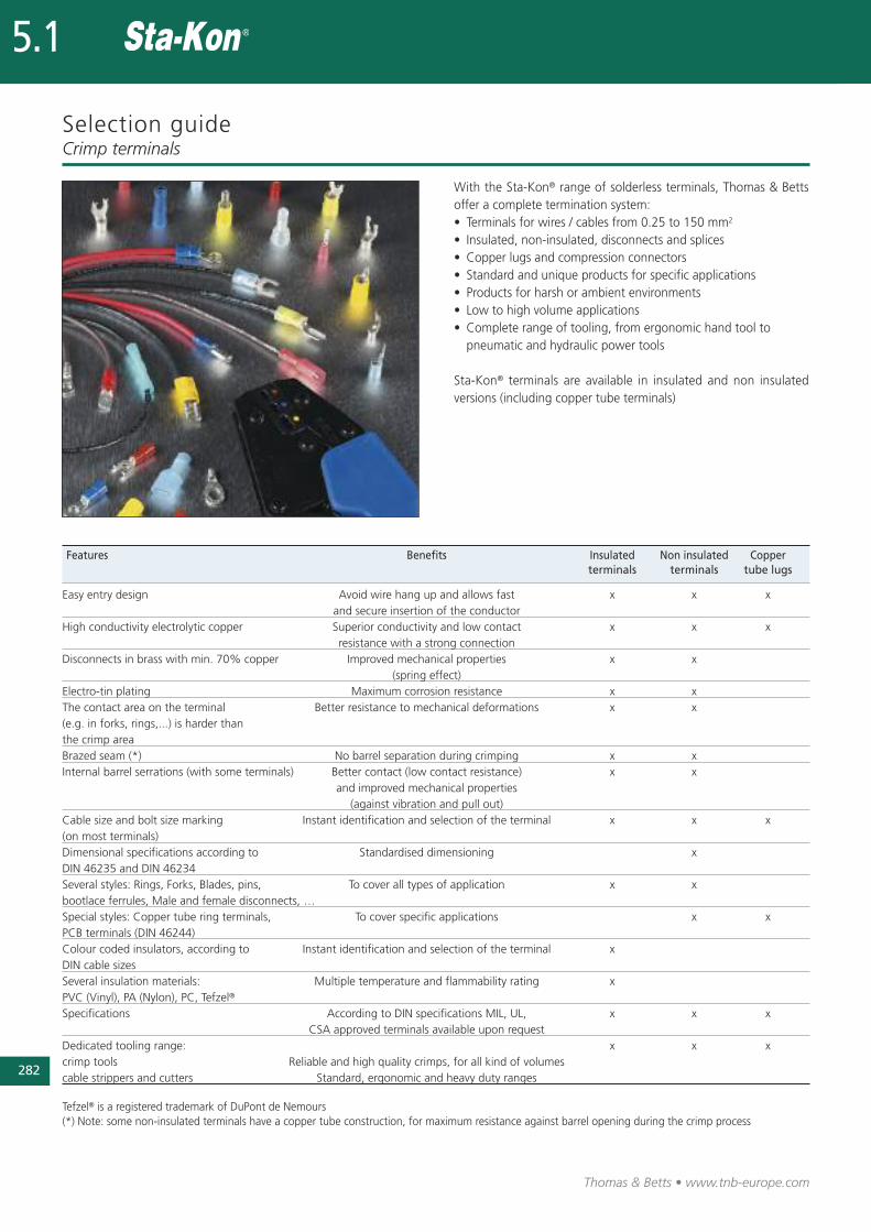
With the Sta-Kon® range of solderless terminals, Thomas & Bettsoffer a complete termination system:• Terminals for wires / cables from 0.25 to 150 mm2
• Insulated, non-insulated, disconnects and splices• Copper lugs and compression connectors• Standard and unique products for specific applications• Products for harsh or ambient environments• Low to high volume applications• Complete range of tooling, from ergonomic hand tool to pneumatic and hydraulic power tools
Sta-Kon® terminals are available in insulated and non insulatedversions (including copper tube terminals)
Crimp terminals
Features Benefits Insulated Non insulated Copper terminals terminals tube lugs
Easy entry design Avoid wire hang up and allows fast x x xand secure insertion of the conductor
High conductivity electrolytic copper Superior conductivity and low contact x x xresistance with a strong connection
Disconnects in brass with min. 70% copper Improved mechanical properties x x(spring effect)
Electro-tin plating Maximum corrosion resistance x xThe contact area on the terminal Better resistance to mechanical deformations x x(e.g. in forks, rings,...) is harder thanthe crimp areaBrazed seam (*) No barrel separation during crimping x xInternal barrel serrations (with some terminals) Better contact (low contact resistance) x x
and improved mechanical properties(against vibration and pull out)
Cable size and bolt size marking Instant identification and selection of the terminal x x x(on most terminals)Dimensional specifications according to Standardised dimensioning xDIN 46235 and DIN 46234Several styles: Rings, Forks, Blades, pins, To cover all types of application x xbootlace ferrules, Male and female disconnects, …Special styles: Copper tube ring terminals, To cover specific applications x xPCB terminals (DIN 46244)Colour coded insulators, according to Instant identification and selection of the terminal xDIN cable sizesSeveral insulation materials: Multiple temperature and flammability rating xPVC (Vinyl), PA (Nylon), PC, Tefzel®
Specifications According to DIN specifications MIL, UL, x x xCSA approved terminals available upon request
Dedicated tooling range: x x xcrimp tools Reliable and high quality crimps, for all kind of volumescable strippers and cutters Standard, ergonomic and heavy duty ranges
Tefzel® is a registered trademark of DuPont de Nemours(*) Note: some non-insulated terminals have a copper tube construction, for maximum resistance against barrel opening during the crimp process

Selection guideCrimp terminals
283
Thomas & Betts • www.tnb-europe.com
5.1
Terminal type Material Plating Marking Metal Insulation Colour Cable Flammability Page barrel coding insertion rating N°
INSULATED TERMINALSRing Copper Tin plated Wire size & Brazed PC / PVC / PA yes Easy entry UL 94 V-0 & 284
bolt size seam UL 94 V-2
Fork Copper Tin plated Wire size & Brazed PC / PVC / PA yes Easy entry UL 94 V-0 & 287bolt size seam UL 94 V-2
Pin Electrolytic Tin plated - Brazed PC yes Easy entry UL 94 V-2 290Copper seam
Blade Electrolytic Tin plated Wire size Brazed PC yes Easy entry UL 94 V-2 291Copper seam
Bootlace Copper Tin plated - Copper PA yes - UL 94 V-2 292tube
Disconnect Brass with Tin plated - Brazed PC / PVC / PA yes Easy entry UL 94 V-0 & 29370% copper** seam* UL 94 V-2
Bullet Phosphor Tin plated - Brazed PC / PVC yes Easy entry UL 94 V-0 & 296bronze / Brass seam* UL 94 V-2
Splice Electrolytic Tin plated - Brazed PA / PC / yes Easy entry UL 94 V-2 298Copper / Brass seam heat shrink
insulation / PP
NON-INSULATED TERMINALSRing Electrolytic Electro- Wire size & Brazed - - Easy entry - 300
Copper tin plating bolt size seam
Fork Electrolytic Electro- Wire size & Brazed - - Easy entry - 301Copper tin plating bolt size seam
Pin Electrolytic Tin plated - - - - - - 302Copper
Splice Copper Tin plated - Tubular - - Easy entry - 302construction
Disconnect Brass with Tin plated - - - - - - 30570% copper
Solder tabs Brass with Tin plated - - - - - - 30770% copper
COPPER TUBE LUGS
Ring Electrolytic Tin plated Wire size & Copper - - Easy entry - 303
Copper bolt size tube
* Non brazed, with brass support sleeve ** 100% Brass for MTB1-TB
284
Thomas & Betts • www.tnb-europe.com
5.1
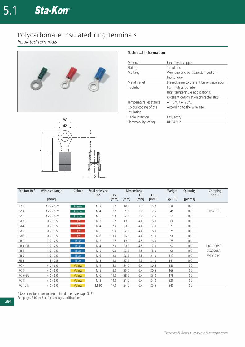
Polycarbonate insulated ring terminals
Technical Information
Material Electrolytic copperPlating Tin platedMarking Wire size and bolt size stamped on
the tongueMetal barrel Brazed seam to prevent barrel separationInsulation PC = Polycarbonate
High temperature applications, excellent deformation characteristics
Temperature resistance +115°C / +125°CColour coding of the According to the wire size insulationCable insertion Easy entry Flammability rating UL 94 V-2
Insulated terminals
Product Ref. Wire size range Colour Stud hole size Dimensions Weight Quantity Crimping d2 W L D L1 tool*
[mm2] [mm] [mm] [mm] [mm] [g/100] [pieces]
RZ 3 0.25 - 0.75 Green M 3 5.5 18.0 3.2 15.0 36 100
RZ 4 0.25 - 0.75 Green M 4 7.5 21.0 3.2 17.5 45 100 ERG2510
RZ 5 0.25 - 0.75 Green M 5 9.0 22.0 3.2 17.5 51 100
RA3RR 0.5 - 1.5 Red M 3 5.5 19.0 4.0 16.0 60 100
RA4RR 0.5 - 1.5 Red M 4 7.0 20.5 4.0 17.0 71 100
RA5RR 0.5 - 1.5 Red M 5 9.0 22.5 4.0 18.0 79 100
RA6RR 0.5 - 1.5 Red M 6 11.0 26.5 4.0 21.0 96 100
RB 3 1.5 - 2.5 Blue M 3 5.5 19.0 4.5 16.0 75 100
RB 4-EU 1.5 - 2.5 Blue M 4 7.0 20.5 4.5 17.0 92 100 ERG2000KE
RB 5 1.5 - 2.5 Blue M 5 9.0 22.5 4.5 18.0 96 100 ERG2001A
RB 6 1.5 - 2.5 Blue M 6 11.0 26.5 4.5 21.0 117 100 WT2124Y
RB 8 1.5 - 2.5 Blue M 8 14.0 27.5 4.5 21.0 141 100
RC 4 4.0 - 6.0 Yellow M 4 8.0 24.0 6.4 20.5 158 50
RC 5 4.0 - 6.0 Yellow M 5 9.0 25.0 6.4 20.5 166 50
RC 6-EU 4.0 - 6.0 Yellow M 6 11.0 28.5 6.4 23.0 179 50
RC 8 4.0 - 6.0 Yellow M 8 14.0 31.0 6.4 24.0 220 50
RC 10 E 4.0 - 6.0 Yellow M 10 17.0 34.0 6.4 25.5 245 50
* Use selection chart to determine die set (see page 316)See pages 310 to 316 for tooling specifications
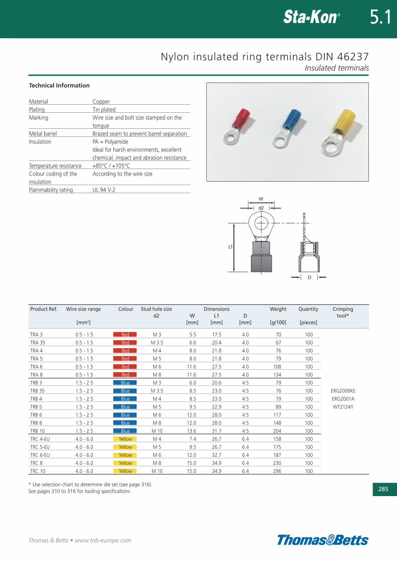
Nylon insulated ring terminals DIN 46237
Technical Information
Material CopperPlating Tin platedMarking Wire size and bolt size stamped on the
tongueMetal barrel Brazed seam to prevent barrel separationInsulation PA = Polyamide
Ideal for harsh environments, excellent chemical, impact and abrasion resistance
Temperature resistance +85°C / +105°CColour coding of the According to the wire sizeinsulationFlammability rating UL 94 V-2
Insulated terminals
285
Thomas & Betts • www.tnb-europe.com
5.1
Product Ref. Wire size range Colour Stud hole size Dimensions Weight Quantity Crimping d2 W L1 D tool*
[mm2] [mm] [mm] [mm] [g/100] [pieces]
TRA 3 0.5 - 1.5 Red M 3 5.5 17.5 4.0 70 100
TRA 35 0.5 - 1.5 Red M 3.5 6.6 20.4 4.0 67 100
TRA 4 0.5 - 1.5 Red M 4 8.0 21.8 4.0 76 100
TRA 5 0.5 - 1.5 Red M 5 8.0 21.8 4.0 79 100
TRA 6 0.5 - 1.5 Red M 6 11.6 27.5 4.0 108 100
TRA 8 0.5 - 1.5 Red M 8 11.6 27.5 4.0 134 100
TRB 3 1.5 - 2.5 Blue M 3 6.0 20.6 4.5 79 100
TRB 35 1.5 - 2.5 Blue M 3.5 8.5 23.0 4.5 76 100 ERG2000KE
TRB 4 1.5 - 2.5 Blue M 4 8.5 23.0 4.5 79 100 ERG2001A
TRB 5 1.5 - 2.5 Blue M 5 9.5 22.9 4.5 89 100 WT2124Y
TRB 6 1.5 - 2.5 Blue M 6 12.0 28.0 4.5 117 100
TRB 8 1.5 - 2.5 Blue M 8 12.0 28.0 4.5 148 100
TRB 10 1.5 - 2.5 Blue M 10 13.6 31.7 4.5 204 100
TRC 4-EU 4.0 - 6.0 Yellow M 4 7.4 26.7 6.4 158 100
TRC 5-EU 4.0 - 6.0 Yellow M 5 9.5 26.7 6.4 175 100
TRC 6-EU 4.0 - 6.0 Yellow M 6 12.0 32.7 6.4 187 100
TRC 8 4.0 - 6.0 Yellow M 8 15.0 34.9 6.4 230 100
TRC 10 4.0 - 6.0 Yellow M 10 15.0 34.9 6.4 296 100
* Use selection chart to determine die set (see page 316)See pages 310 to 316 for tooling specifications
286
Thomas & Betts • www.tnb-europe.com
5.1
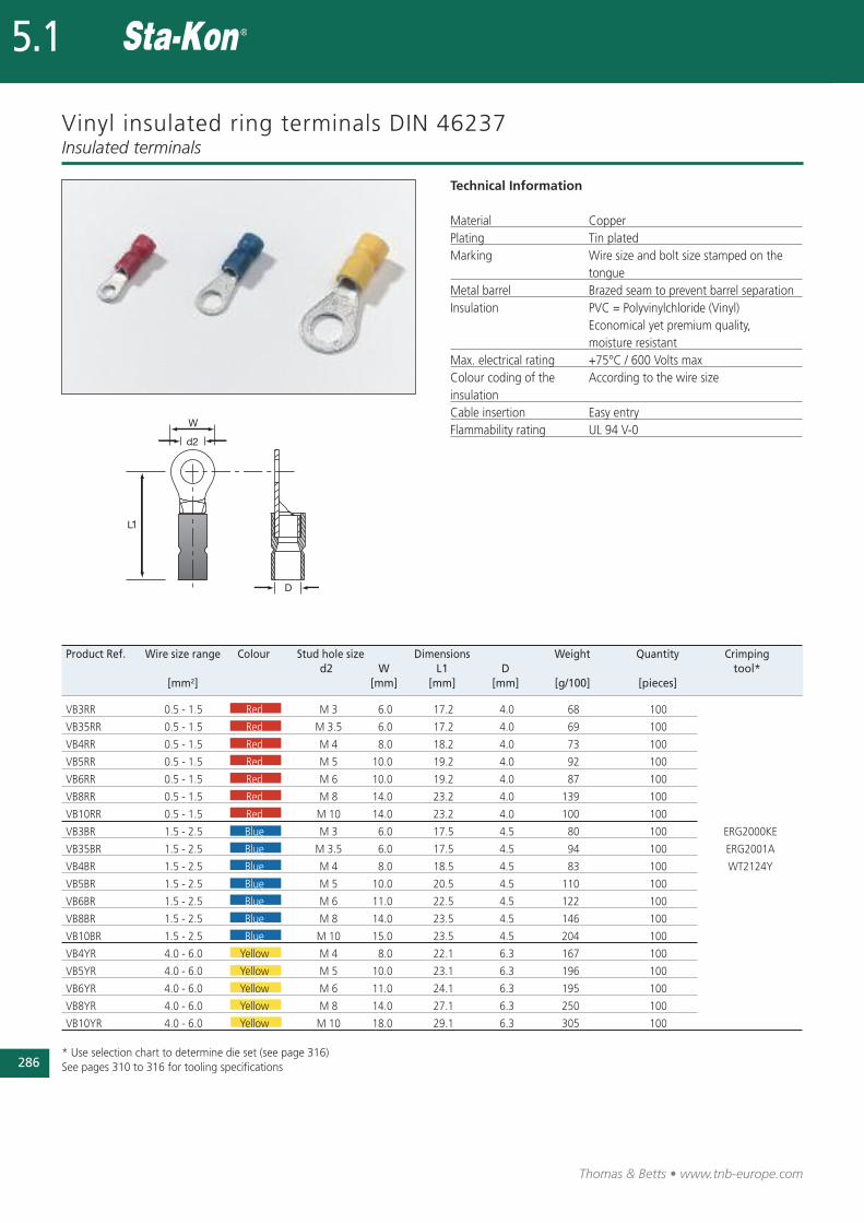
Vinyl insulated ring terminals DIN 46237
Technical Information
Material CopperPlating Tin platedMarking Wire size and bolt size stamped on the
tongueMetal barrel Brazed seam to prevent barrel separationInsulation PVC = Polyvinylchloride (Vinyl)
Economical yet premium quality, moisture resistant
Max. electrical rating +75°C / 600 Volts maxColour coding of the According to the wire sizeinsulationCable insertion Easy entry Flammability rating UL 94 V-0
Insulated terminals
Product Ref. Wire size range Colour Stud hole size Dimensions Weight Quantity Crimping d2 W L1 D tool*
[mm2] [mm] [mm] [mm] [g/100] [pieces]
VB3RR 0.5 - 1.5 Red M 3 6.0 17.2 4.0 68 100
VB35RR 0.5 - 1.5 Red M 3.5 6.0 17.2 4.0 69 100
VB4RR 0.5 - 1.5 Red M 4 8.0 18.2 4.0 73 100
VB5RR 0.5 - 1.5 Red M 5 10.0 19.2 4.0 92 100
VB6RR 0.5 - 1.5 Red M 6 10.0 19.2 4.0 87 100
VB8RR 0.5 - 1.5 Red M 8 14.0 23.2 4.0 139 100
VB10RR 0.5 - 1.5 Red M 10 14.0 23.2 4.0 100 100
VB3BR 1.5 - 2.5 Blue M 3 6.0 17.5 4.5 80 100 ERG2000KE
VB35BR 1.5 - 2.5 Blue M 3.5 6.0 17.5 4.5 94 100 ERG2001A
VB4BR 1.5 - 2.5 Blue M 4 8.0 18.5 4.5 83 100 WT2124Y
VB5BR 1.5 - 2.5 Blue M 5 10.0 20.5 4.5 110 100
VB6BR 1.5 - 2.5 Blue M 6 11.0 22.5 4.5 122 100
VB8BR 1.5 - 2.5 Blue M 8 14.0 23.5 4.5 146 100
VB10BR 1.5 - 2.5 Blue M 10 15.0 23.5 4.5 204 100
VB4YR 4.0 - 6.0 Yellow M 4 8.0 22.1 6.3 167 100
VB5YR 4.0 - 6.0 Yellow M 5 10.0 23.1 6.3 196 100
VB6YR 4.0 - 6.0 Yellow M 6 11.0 24.1 6.3 195 100
VB8YR 4.0 - 6.0 Yellow M 8 14.0 27.1 6.3 250 100
VB10YR 4.0 - 6.0 Yellow M 10 18.0 29.1 6.3 305 100
* Use selection chart to determine die set (see page 316)See pages 310 to 316 for tooling specifications
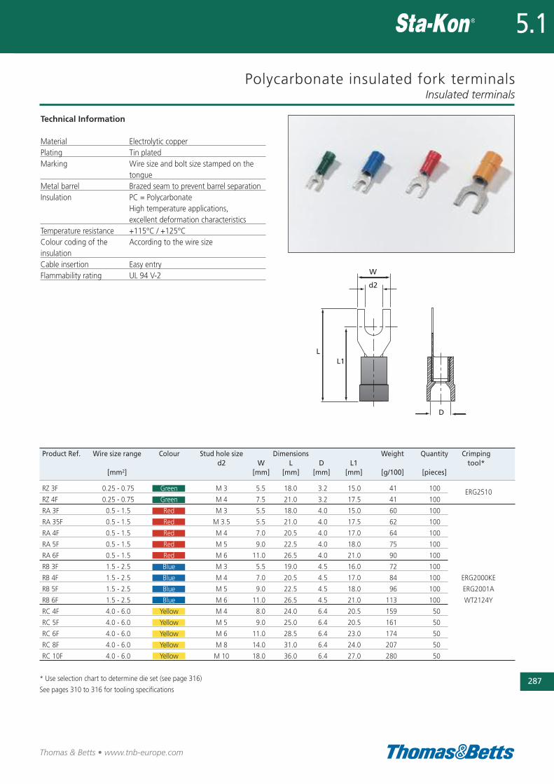
Polycarbonate insulated fork terminals
Technical Information
Material Electrolytic copperPlating Tin platedMarking Wire size and bolt size stamped on the
tongueMetal barrel Brazed seam to prevent barrel separationInsulation PC = Polycarbonate
High temperature applications, excellent deformation characteristics
Temperature resistance +115°C / +125°CColour coding of the According to the wire size insulationCable insertion Easy entry Flammability rating UL 94 V-2
Insulated terminals
287
Thomas & Betts • www.tnb-europe.com
5.1
Product Ref. Wire size range Colour Stud hole size Dimensions Weight Quantity Crimping d2 W L D L1 tool*
[mm2] [mm] [mm] [mm] [mm] [g/100] [pieces]
RZ 3F 0.25 - 0.75 Green M 3 5.5 18.0 3.2 15.0 41 100
RZ 4F 0.25 - 0.75 Green M 4 7.5 21.0 3.2 17.5 41 100ERG2510
RA 3F 0.5 - 1.5 Red M 3 5.5 18.0 4.0 15.0 60 100
RA 35F 0.5 - 1.5 Red M 3.5 5.5 21.0 4.0 17.5 62 100
RA 4F 0.5 - 1.5 Red M 4 7.0 20.5 4.0 17.0 64 100
RA 5F 0.5 - 1.5 Red M 5 9.0 22.5 4.0 18.0 75 100
RA 6F 0.5 - 1.5 Red M 6 11.0 26.5 4.0 21.0 90 100
RB 3F 1.5 - 2.5 Blue M 3 5.5 19.0 4.5 16.0 72 100
RB 4F 1.5 - 2.5 Blue M 4 7.0 20.5 4.5 17.0 84 100 ERG2000KE
RB 5F 1.5 - 2.5 Blue M 5 9.0 22.5 4.5 18.0 96 100 ERG2001A
RB 6F 1.5 - 2.5 Blue M 6 11.0 26.5 4.5 21.0 113 100 WT2124Y
RC 4F 4.0 - 6.0 Yellow M 4 8.0 24.0 6.4 20.5 159 50
RC 5F 4.0 - 6.0 Yellow M 5 9.0 25.0 6.4 20.5 161 50
RC 6F 4.0 - 6.0 Yellow M 6 11.0 28.5 6.4 23.0 174 50
RC 8F 4.0 - 6.0 Yellow M 8 14.0 31.0 6.4 24.0 207 50
RC 10F 4.0 - 6.0 Yellow M 10 18.0 36.0 6.4 27.0 280 50
* Use selection chart to determine die set (see page 316)
See pages 310 to 316 for tooling specifications
288
Thomas & Betts • www.tnb-europe.com
5.1
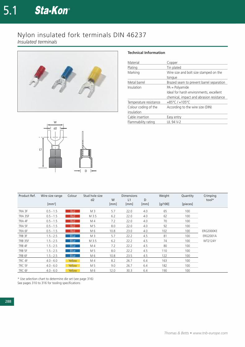
Nylon insulated fork terminals DIN 46237
Technical Information
Material CopperPlating Tin platedMarking Wire size and bolt size stamped on the
tongueMetal barrel Brazed seam to prevent barrel separationInsulation PA = Polyamide
Ideal for harsh environments, excellent chemical, impact and abrasion resistance
Temperature resistance +85°C / +105°CColour coding of the According to the wire size (DIN)insulationCable insertion Easy entry Flammability rating UL 94 V-2
Insulated terminals
Product Ref. Wire size range Colour Stud hole size Dimensions Weight Quantity Crimping d2 W L1 D tool*
[mm2] [mm] [mm] [mm] [g/100] [pieces]
TRA 3F 0.5 - 1.5 Red M 3 5.7 22.0 4.0 65 100
TRA 35F 0.5 - 1.5 Red M 3.5 6.2 22.0 4.0 62 100
TRA 4F 0.5 - 1.5 Red M 4 7.2 22.0 4.0 70 100
TRA 5F 0.5 - 1.5 Red M 5 8.0 22.0 4.0 92 100
TRA 6F 0.5 - 1.5 Red M 6 10.8 23.0 4.0 102 100 ERG2000KE
TRB 3F 1.5 - 2.5 Blue M 3 5.7 22.2 4.5 81 100 ERG2001A
TRB 35F 1.5 - 2.5 Blue M 3.5 6.2 22.2 4.5 74 100 WT2124Y
TRB 4F 1.5 - 2.5 Blue M 4 7.2 22.2 4.5 80 100
TRB 5F 1.5 - 2.5 Blue M 5 8.0 22.2 4.5 110 100
TRB 6F 1.5 - 2.5 Blue M 6 10.8 23.5 4.5 122 100
TRC 4F 4.0 - 6.0 Yellow M 4 8.2 26.7 6.4 163 100
TRC 5F 4.0 - 6.0 Yellow M 5 9.0 26.7 6.4 182 100
TRC 6F 4.0 - 6.0 Yellow M 6 12.0 30.3 6.4 190 100
* Use selection chart to determine die set (see page 316)See pages 310 to 316 for tooling specifications
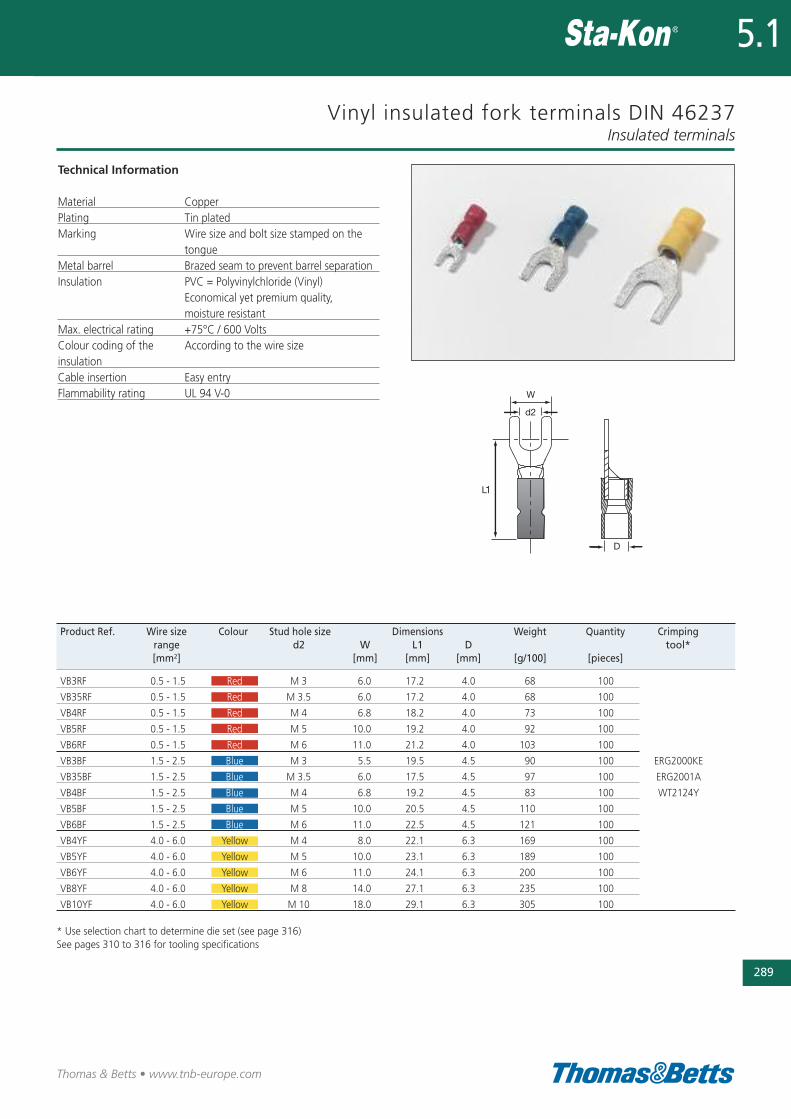
Vinyl insulated fork terminals DIN 46237
Technical Information
Material CopperPlating Tin platedMarking Wire size and bolt size stamped on the
tongueMetal barrel Brazed seam to prevent barrel separationInsulation PVC = Polyvinylchloride (Vinyl)
Economical yet premium quality, moisture resistant
Max. electrical rating +75°C / 600 VoltsColour coding of the According to the wire size insulationCable insertion Easy entry Flammability rating UL 94 V-0
Insulated terminals
289
Thomas & Betts • www.tnb-europe.com
5.1
Product Ref. Wire size Colour Stud hole size Dimensions Weight Quantity Crimping range d2 W L1 D tool*[mm2] [mm] [mm] [mm] [g/100] [pieces]
VB3RF 0.5 - 1.5 Red M 3 6.0 17.2 4.0 68 100
VB35RF 0.5 - 1.5 Red M 3.5 6.0 17.2 4.0 68 100
VB4RF 0.5 - 1.5 Red M 4 6.8 18.2 4.0 73 100
VB5RF 0.5 - 1.5 Red M 5 10.0 19.2 4.0 92 100
VB6RF 0.5 - 1.5 Red M 6 11.0 21.2 4.0 103 100
VB3BF 1.5 - 2.5 Blue M 3 5.5 19.5 4.5 90 100 ERG2000KE
VB35BF 1.5 - 2.5 Blue M 3.5 6.0 17.5 4.5 97 100 ERG2001A
VB4BF 1.5 - 2.5 Blue M 4 6.8 19.2 4.5 83 100 WT2124Y
VB5BF 1.5 - 2.5 Blue M 5 10.0 20.5 4.5 110 100
VB6BF 1.5 - 2.5 Blue M 6 11.0 22.5 4.5 121 100
VB4YF 4.0 - 6.0 Yellow M 4 8.0 22.1 6.3 169 100
VB5YF 4.0 - 6.0 Yellow M 5 10.0 23.1 6.3 189 100
VB6YF 4.0 - 6.0 Yellow M 6 11.0 24.1 6.3 200 100
VB8YF 4.0 - 6.0 Yellow M 8 14.0 27.1 6.3 235 100
VB10YF 4.0 - 6.0 Yellow M 10 18.0 29.1 6.3 305 100
* Use selection chart to determine die set (see page 316)See pages 310 to 316 for tooling specifications
290
Thomas & Betts • www.tnb-europe.com
5.1
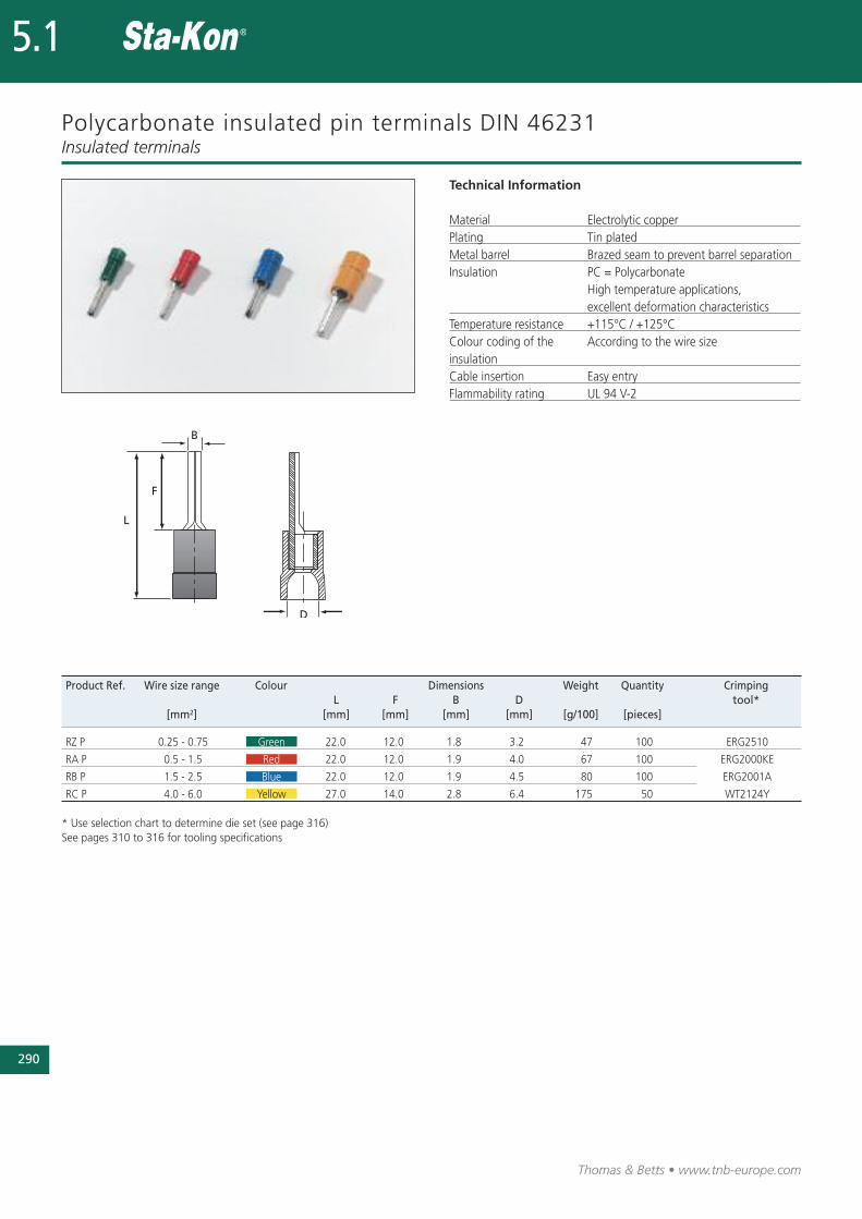
Polycarbonate insulated pin terminals DIN 46231
Technical Information
Material Electrolytic copperPlating Tin platedMetal barrel Brazed seam to prevent barrel separationInsulation PC = Polycarbonate
High temperature applications, excellent deformation characteristics
Temperature resistance +115°C / +125°CColour coding of the According to the wire size insulationCable insertion Easy entry Flammability rating UL 94 V-2
Insulated terminals
Product Ref. Wire size range Colour Dimensions Weight Quantity Crimping L F B D tool*
[mm2] [mm] [mm] [mm] [mm] [g/100] [pieces]
RZ P 0.25 - 0.75 Green 22.0 12.0 1.8 3.2 47 100 ERG2510
RA P 0.5 - 1.5 Red 22.0 12.0 1.9 4.0 67 100 ERG2000KE
RB P 1.5 - 2.5 Blue 22.0 12.0 1.9 4.5 80 100 ERG2001A
RC P 4.0 - 6.0 Yellow 27.0 14.0 2.8 6.4 175 50 WT2124Y
* Use selection chart to determine die set (see page 316)See pages 310 to 316 for tooling specifications
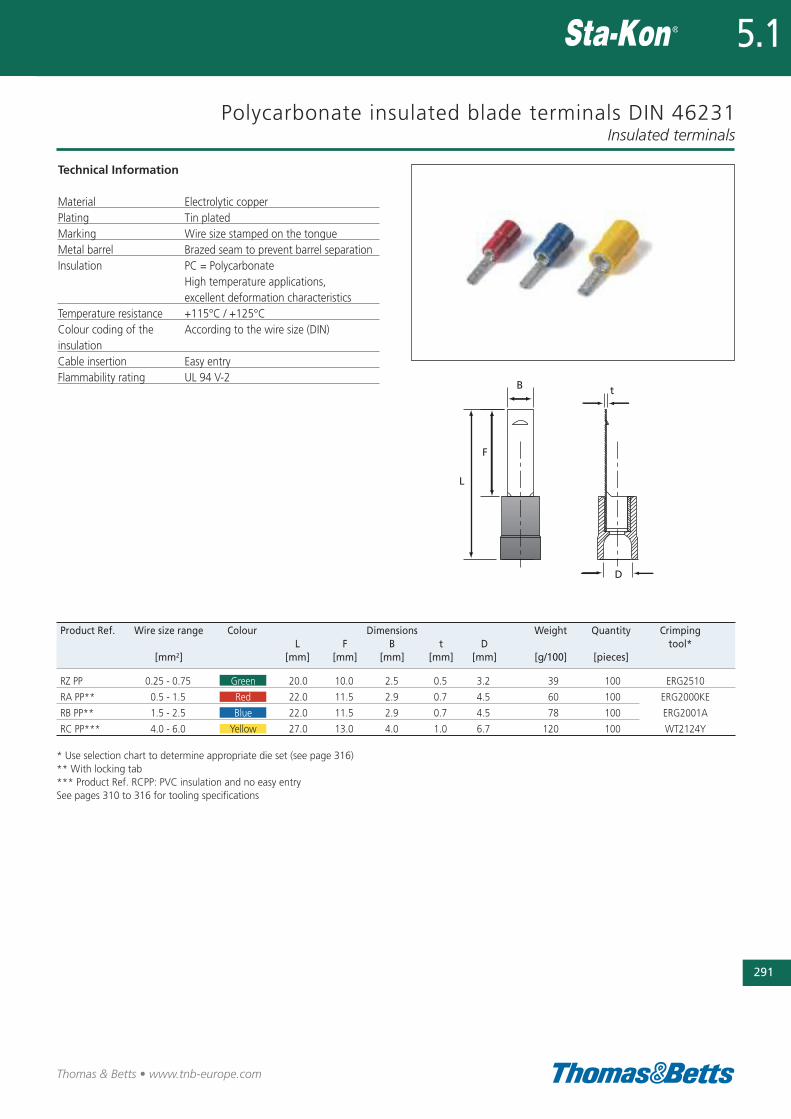
Polycarbonate insulated blade terminals DIN 46231
Technical Information
Material Electrolytic copperPlating Tin platedMarking Wire size stamped on the tongueMetal barrel Brazed seam to prevent barrel separationInsulation PC = Polycarbonate
High temperature applications, excellent deformation characteristics
Temperature resistance +115°C / +125°CColour coding of the According to the wire size (DIN)insulationCable insertion Easy entry Flammability rating UL 94 V-2
Insulated terminals
291
Thomas & Betts • www.tnb-europe.com
5.1
Product Ref. Wire size range Colour Dimensions Weight Quantity Crimping L F B t D tool*
[mm2] [mm] [mm] [mm] [mm] [mm] [g/100] [pieces]
RZ PP 0.25 - 0.75 Green 20.0 10.0 2.5 0.5 3.2 39 100 ERG2510
RA PP** 0.5 - 1.5 Red 22.0 11.5 2.9 0.7 4.5 60 100 ERG2000KE
RB PP** 1.5 - 2.5 Blue 22.0 11.5 2.9 0.7 4.5 78 100 ERG2001A
RC PP*** 4.0 - 6.0 Yellow 27.0 13.0 4.0 1.0 6.7 120 100 WT2124Y
* Use selection chart to determine appropriate die set (see page 316)** With locking tab*** Product Ref. RCPP: PVC insulation and no easy entry See pages 310 to 316 for tooling specifications
292
Thomas & Betts • www.tnb-europe.com
5.1
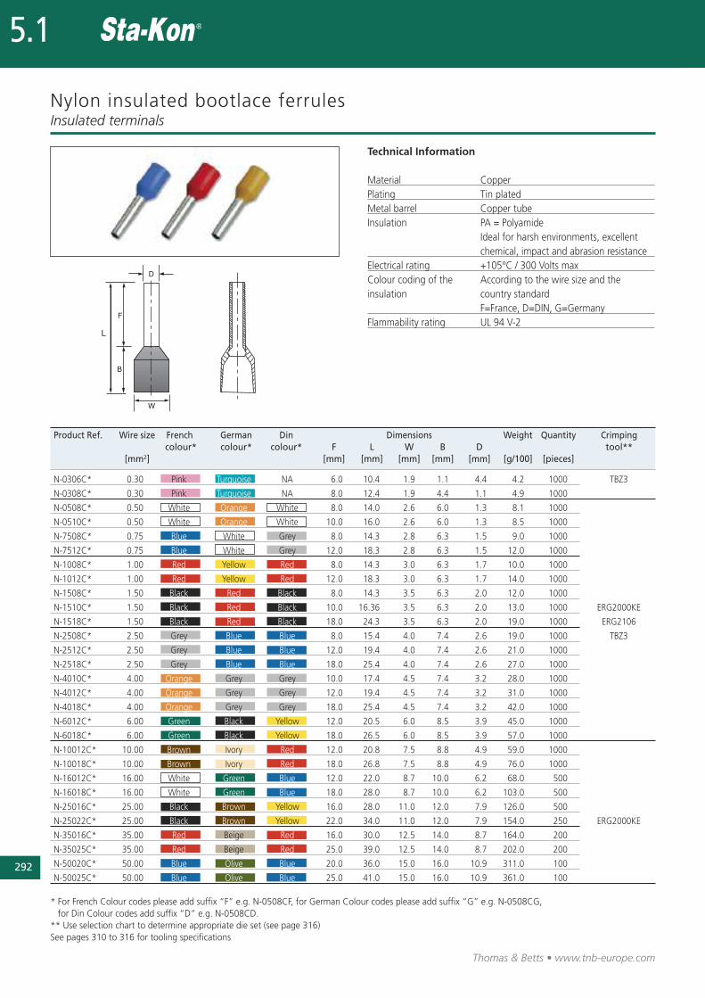
Nylon insulated bootlace ferrules
Technical Information
Material CopperPlating Tin platedMetal barrel Copper tubeInsulation PA = Polyamide
Ideal for harsh environments, excellent chemical, impact and abrasion resistance
Electrical rating +105°C / 300 Volts maxColour coding of the According to the wire size and the insulation country standard
F=France, D=DIN, G=Germany Flammability rating UL 94 V-2
Insulated terminals
Product Ref. Wire size French German Din Dimensions Weight Quantity Crimping colour* colour* colour* F L W B D tool**
[mm2] [mm] [mm] [mm] [mm] [mm] [g/100] [pieces]
N-0306C* 0.30 Pink Turquoise NA 6.0 10.4 1.9 1.1 4.4 4.2 1000 TBZ3
N-0308C* 0.30 Pink Turquoise NA 8.0 12.4 1.9 4.4 1.1 4.9 1000
N-0508C* 0.50 White Orange White 8.0 14.0 2.6 6.0 1.3 8.1 1000
N-0510C* 0.50 White Orange White 10.0 16.0 2.6 6.0 1.3 8.5 1000
N-7508C* 0.75 Blue White Grey 8.0 14.3 2.8 6.3 1.5 9.0 1000
N-7512C* 0.75 Blue White Grey 12.0 18.3 2.8 6.3 1.5 12.0 1000
N-1008C* 1.00 Red Yellow Red 8.0 14.3 3.0 6.3 1.7 10.0 1000
N-1012C* 1.00 Red Yellow Red 12.0 18.3 3.0 6.3 1.7 14.0 1000
N-1508C* 1.50 Black Red Black 8.0 14.3 3.5 6.3 2.0 12.0 1000
N-1510C* 1.50 Black Red Black 10.0 16.36 3.5 6.3 2.0 13.0 1000 ERG2000KE
N-1518C* 1.50 Black Red Black 18.0 24.3 3.5 6.3 2.0 19.0 1000 ERG2106
N-2508C* 2.50 Grey Blue Blue 8.0 15.4 4.0 7.4 2.6 19.0 1000 TBZ3
N-2512C* 2.50 Grey Blue Blue 12.0 19.4 4.0 7.4 2.6 21.0 1000
N-2518C* 2.50 Grey Blue Blue 18.0 25.4 4.0 7.4 2.6 27.0 1000
N-4010C* 4.00 Orange Grey Grey 10.0 17.4 4.5 7.4 3.2 28.0 1000
N-4012C* 4.00 Orange Grey Grey 12.0 19.4 4.5 7.4 3.2 31.0 1000
N-4018C* 4.00 Orange Grey Grey 18.0 25.4 4.5 7.4 3.2 42.0 1000
N-6012C* 6.00 Green Black Yellow 12.0 20.5 6.0 8.5 3.9 45.0 1000
N-6018C* 6.00 Green Black Yellow 18.0 26.5 6.0 8.5 3.9 57.0 1000
N-10012C* 10.00 Brown Ivory Red 12.0 20.8 7.5 8.8 4.9 59.0 1000
N-10018C* 10.00 Brown Ivory Red 18.0 26.8 7.5 8.8 4.9 76.0 1000
N-16012C* 16.00 White Green Blue 12.0 22.0 8.7 10.0 6.2 68.0 500
N-16018C* 16.00 White Green Blue 18.0 28.0 8.7 10.0 6.2 103.0 500
N-25016C* 25.00 Black Brown Yellow 16.0 28.0 11.0 12.0 7.9 126.0 500
N-25022C* 25.00 Black Brown Yellow 22.0 34.0 11.0 12.0 7.9 154.0 250 ERG2000KE
N-35016C* 35.00 Red Beige Red 16.0 30.0 12.5 14.0 8.7 164.0 200
N-35025C* 35.00 Red Beige Red 25.0 39.0 12.5 14.0 8.7 202.0 200
N-50020C* 50.00 Blue Olive Blue 20.0 36.0 15.0 16.0 10.9 311.0 100
N-50025C* 50.00 Blue Olive Blue 25.0 41.0 15.0 16.0 10.9 361.0 100
* For French Colour codes please add suffix “F” e.g. N-0508CF, for German Colour codes please add suffix “G” e.g. N-0508CG, for Din Colour codes add suffix ”D” e.g. N-0508CD.
** Use selection chart to determine appropriate die set (see page 316)See pages 310 to 316 for tooling specifications
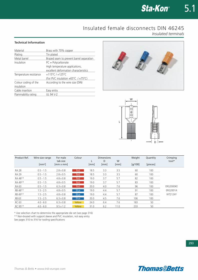
Insulated female disconnects DIN 46245
Technical Information
Material Brass with 70% copperPlating Tin platedMetal barrel Brazed seam to prevent barrel separationInsulation PC = Polycarbonate
High temperature applications, excellent deformation characteristics
Temperature resistance +115°C / +125°C (For PVC insulation +65°C / +75°C)
Colour coding of the According to the wire size (DIN)insulationCable insertion Easy entry Flammability rating UL 94 V-2
Insulated terminals
293
Thomas & Betts • www.tnb-europe.com
5.1
Product Ref. Wire size range For male Colour Dimensions Weight Quantity Crimping tab size L D W tool*
[mm2] [mm x mm] [mm] [mm] [mm] [g/100] [pieces]
RA 28 0.5 - 1.5 2.8 x 0.8 Red 18.5 3.3 3.5 60 100
RA 29 0.5 - 1.5 2.8 x 0.5 Red 18.5 3.3 3.5 60 100
RA 48** 0.5 - 1.5 4.8 x 0.8 Red 19.0 3.7 5.7 82 100
RA 49** 0.5 - 1.5 4.8 x 0.5 Red 19.0 3.7 5.7 83 100
RA 63 0.5 - 1.5 6.3 x 0.8 Red 20.0 4.0 7.6 96 100 ERG2000KE
RB 48** 1.5 - 2.5 4.8 x 0.5 Blue 19.0 4.4 5.7 91 100 ERG2001A
RB 49** 1.5 - 2.5 4.8 x 0.8 Blue 19.0 4.4 5.7 87 100 WT2124Y
RB 63 1.5 - 2.5 6.3 x 0.8 Blue 20.0 4.5 7.6 106 100
RC 63 4.0 - 6.0 6.3 x 0.8 Yellow 24.0 6.4 7.6 183 50
RC 95** 4.0 - 6.0 9.5 x 1.2 Yellow 31.0 6.2 11.0 233 50
* Use selection chart to determine the appropriate die set (see page 316)** Non-brazed with support sleeve and PVC insulation, not easy entrySee pages 310 to 316 for tooling specifications
294
Thomas & Betts • www.tnb-europe.com
5.1
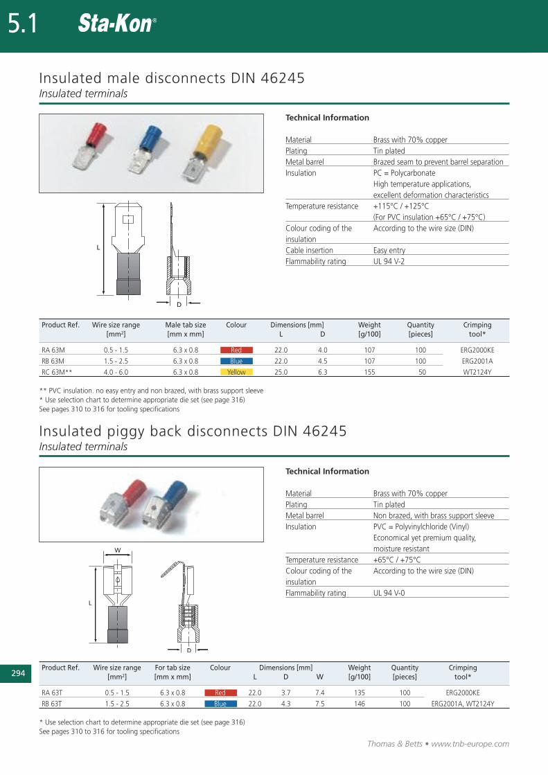
Insulated male disconnects DIN 46245
Technical Information
Material Brass with 70% copperPlating Tin platedMetal barrel Brazed seam to prevent barrel separationInsulation PC = Polycarbonate
High temperature applications, excellent deformation characteristics
Temperature resistance +115°C / +125°C (For PVC insulation +65°C / +75°C)
Colour coding of the According to the wire size (DIN)insulationCable insertion Easy entry Flammability rating UL 94 V-2
Insulated terminals
Product Ref. Wire size range Male tab size Colour Dimensions [mm] Weight Quantity Crimping [mm2] [mm x mm] L D [g/100] [pieces] tool*
RA 63M 0.5 - 1.5 6.3 x 0.8 Red 22.0 4.0 107 100 ERG2000KE
RB 63M 1.5 - 2.5 6.3 x 0.8 Blue 22.0 4.5 107 100 ERG2001A
RC 63M** 4.0 - 6.0 6.3 x 0.8 Yellow 25.0 6.3 155 50 WT2124Y
** PVC insulation. no easy entry and non brazed, with brass support sleeve* Use selection chart to determine appropriate die set (see page 316)See pages 310 to 316 for tooling specifications
Product Ref. Wire size range For tab size Colour Dimensions [mm] Weight Quantity Crimping [mm2] [mm x mm] L D W [g/100] [pieces] tool*
RA 63T 0.5 - 1.5 6.3 x 0.8 Red 22.0 3.7 7.4 135 100 ERG2000KE
RB 63T 1.5 - 2.5 6.3 x 0.8 Blue 22.0 4.3 7.5 146 100 ERG2001A, WT2124Y
* Use selection chart to determine appropriate die set (see page 316)See pages 310 to 316 for tooling specifications
Insulated piggy back disconnects DIN 46245Insulated terminals
Technical Information
Material Brass with 70% copperPlating Tin platedMetal barrel Non brazed, with brass support sleeveInsulation PVC = Polyvinylchloride (Vinyl)
Economical yet premium quality, moisture resistant
Temperature resistance +65°C / +75°CColour coding of the According to the wire size (DIN) insulationFlammability rating UL 94 V-0
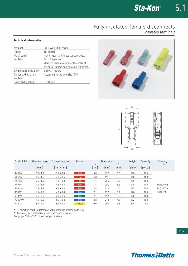
Fully insulated female disconnects
Technical Information
Material Brass with 70% copperPlating Tin platedMetal barrel Non brazed, with brass support sleeveInsulation PA = Polyamide
Ideal for harsh environments, excellent chemical, impact and abrasion resistance
Temperature resistance +85°C / +105°CColour coding of the According to the wire size (DIN) insulationFlammability rating UL 94 V-2
Insulated terminals
295
Thomas & Betts • www.tnb-europe.com
5.1
Product Ref. Wire size range For male tab size Colour Dimensions Weight Quantity Crimping W L D tool*
[mm2] [mm x mm] [mm] [mm] [mm] [g/100] [pieces]
RA 28V 0.5 - 1.5 2.8 x 0.8 Red 5.0 19.3 3.8 110 100
RA 29V 0.5 - 1.5 2.8 x 0.5 Red 5.0 19.3 3.8 110 100
RA 48V 0.5 - 1.5 4.8 x 0.8 Red 7.4 20.2 3.6 115 100
RA 49V 0.5 - 1.5 4.8 x 0.5 Red 7.4 20.2 3.6 115 100 ERG2000KE
RA 63V** 0.5 - 1.5 6.3 x 0.8 Red 8.8 21.0 4.0 123 100 ERG2001A
RB 48V 1.5 - 2.5 4.8 x 0.8 Blue 7.1 19.5 3.9 120 100 WT2124Y
RB 49V 1.5 - 2.5 4.8 x 0.5 Blue 7.1 19.5 3.9 120 100
RB 63V** 1.5 - 2.5 6.3 x 0.8 Blue 8.8 21.0 4.5 132 100
RC 63V 4.0 - 6.0 6.3 x 0.8 Yellow 9.0 26.0 5.3 215 50
* Use selection chart to determine appropriate die set (see page 316)** Easy entry and brazed barrel, polycarbonate insulatorSee pages 310 to 316 for tooling specifications
296
Thomas & Betts • www.tnb-europe.com
5.1
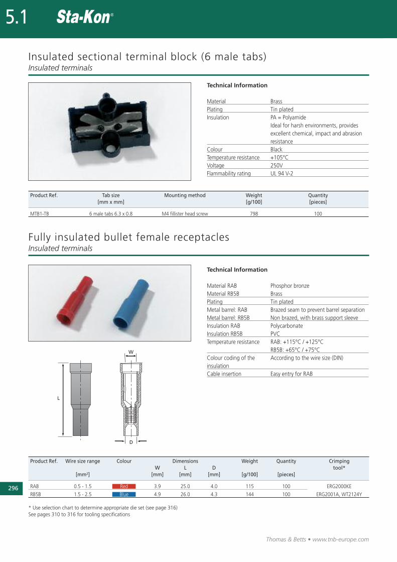
Insulated sectional terminal block (6 male tabs)
Technical Information
Material BrassPlating Tin platedInsulation PA = Polyamide
Ideal for harsh environments, provides excellent chemical, impact and abrasion resistance
Colour BlackTemperature resistance +105°CVoltage 250V Flammability rating UL 94 V-2
Insulated terminals
Product Ref. Tab size Mounting method Weight Quantity[mm x mm] [g/100] [pieces]
MTB1-TB 6 male tabs 6.3 x 0.8 M4 fillister head screw 798 100
Product Ref. Wire size range Colour Dimensions Weight Quantity Crimping W L D tool*
[mm2] [mm] [mm] [mm] [g/100] [pieces]
RAB 0.5 - 1.5 Red 3.9 25.0 4.0 115 100 ERG2000KE
RB5B 1.5 - 2.5 Blue 4.9 26.0 4.3 144 100 ERG2001A, WT2124Y
* Use selection chart to determine appropriate die set (see page 316)See pages 310 to 316 for tooling specifications
Fully insulated bullet female receptaclesInsulated terminals
Technical Information
Material RAB Phosphor bronzeMaterial RB5B BrassPlating Tin platedMetal barrel: RAB Brazed seam to prevent barrel separationMetal barrel: RB5B Non brazed, with brass support sleeveInsulation RAB PolycarbonateInsulation RB5B PVCTemperature resistance RAB: +115°C / +125°C
RB5B: +65°C / +75°CColour coding of the According to the wire size (DIN)insulationCable insertion Easy entry for RAB
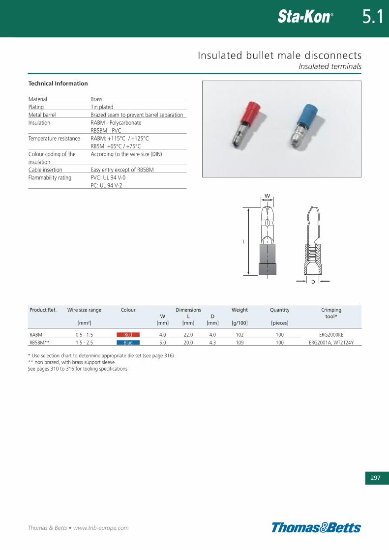
Insulated bullet male disconnects
Technical Information
Material BrassPlating Tin platedMetal barrel Brazed seam to prevent barrel separationInsulation RABM - Polycarbonate
RB5BM - PVCTemperature resistance RABM: +115°C / +125°C
RB5M: +65°C / +75°CColour coding of the According to the wire size (DIN)insulationCable insertion Easy entry except of RB5BMFlammability rating PVC: UL 94 V-0
PC: UL 94 V-2
Insulated terminals
297
Thomas & Betts • www.tnb-europe.com
5.1
Product Ref. Wire size range Colour Dimensions Weight Quantity Crimping W L D tool*
[mm2] [mm] [mm] [mm] [g/100] [pieces]
RABM 0.5 - 1.5 Red 4.0 22.0 4.0 102 100 ERG2000KE
RB5BM** 1.5 - 2.5 Blue 5.0 20.0 4.3 109 100 ERG2001A, WT2124Y
* Use selection chart to determine appropriate die set (see page 316)** non brazed, with brass support sleeveSee pages 310 to 316 for tooling specifications
298
Thomas & Betts • www.tnb-europe.com
5.1
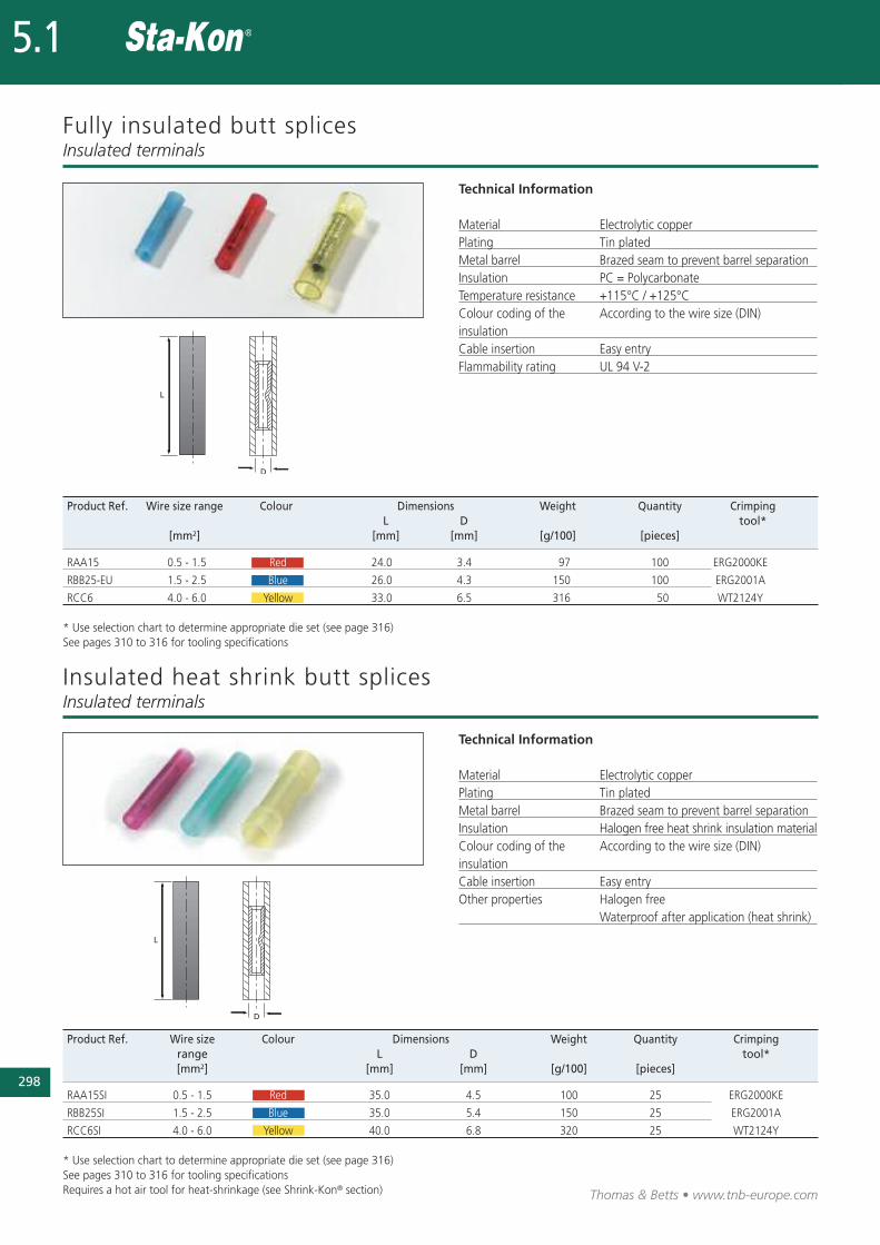
Fully insulated butt splices
Technical Information
Material Electrolytic copperPlating Tin platedMetal barrel Brazed seam to prevent barrel separationInsulation PC = PolycarbonateTemperature resistance +115°C / +125°CColour coding of the According to the wire size (DIN)insulationCable insertion Easy entry Flammability rating UL 94 V-2
Insulated terminals
Product Ref. Wire size range Colour Dimensions Weight Quantity Crimping L D tool*
[mm2] [mm] [mm] [g/100] [pieces]
RAA15 0.5 - 1.5 Red 24.0 3.4 97 100 ERG2000KE
RBB25-EU 1.5 - 2.5 Blue 26.0 4.3 150 100 ERG2001A
RCC6 4.0 - 6.0 Yellow 33.0 6.5 316 50 WT2124Y
* Use selection chart to determine appropriate die set (see page 316)See pages 310 to 316 for tooling specifications
Product Ref. Wire size Colour Dimensions Weight Quantity Crimping range L D tool*[mm2] [mm] [mm] [g/100] [pieces]
RAA15SI 0.5 - 1.5 Red 35.0 4.5 100 25 ERG2000KE
RBB25SI 1.5 - 2.5 Blue 35.0 5.4 150 25 ERG2001A
RCC6SI 4.0 - 6.0 Yellow 40.0 6.8 320 25 WT2124Y
* Use selection chart to determine appropriate die set (see page 316)See pages 310 to 316 for tooling specificationsRequires a hot air tool for heat-shrinkage (see Shrink-Kon® section)
Insulated heat shrink butt splicesInsulated terminals
Technical Information
Material Electrolytic copperPlating Tin platedMetal barrel Brazed seam to prevent barrel separationInsulation Halogen free heat shrink insulation materialColour coding of the According to the wire size (DIN)insulationCable insertion Easy entry Other properties Halogen free
Waterproof after application (heat shrink)
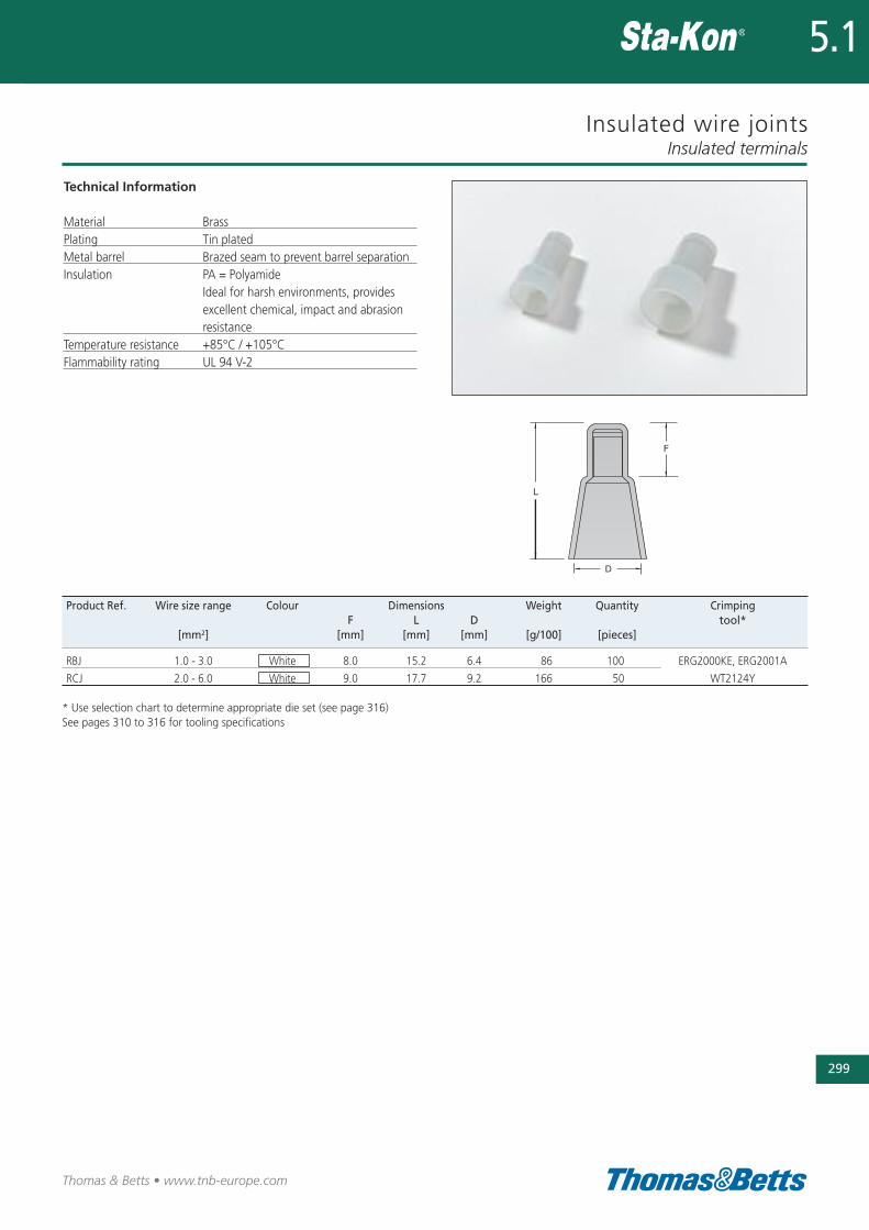
Insulated wire joints
Technical Information
Material BrassPlating Tin platedMetal barrel Brazed seam to prevent barrel separationInsulation PA = Polyamide
Ideal for harsh environments, provides excellent chemical, impact and abrasion resistance
Temperature resistance +85°C / +105°CFlammability rating UL 94 V-2
Insulated terminals
299
Thomas & Betts • www.tnb-europe.com
5.1
Product Ref. Wire size range Colour Dimensions Weight Quantity Crimping F L D tool*
[mm2] [mm] [mm] [mm] [g/100] [pieces]
RBJ 1.0 - 3.0 White 8.0 15.2 6.4 86 100 ERG2000KE, ERG2001A
RCJ 2.0 - 6.0 White 9.0 17.7 9.2 166 50 WT2124Y
* Use selection chart to determine appropriate die set (see page 316)See pages 310 to 316 for tooling specifications
E9809
300
Thomas & Betts • www.tnb-europe.com
5.1
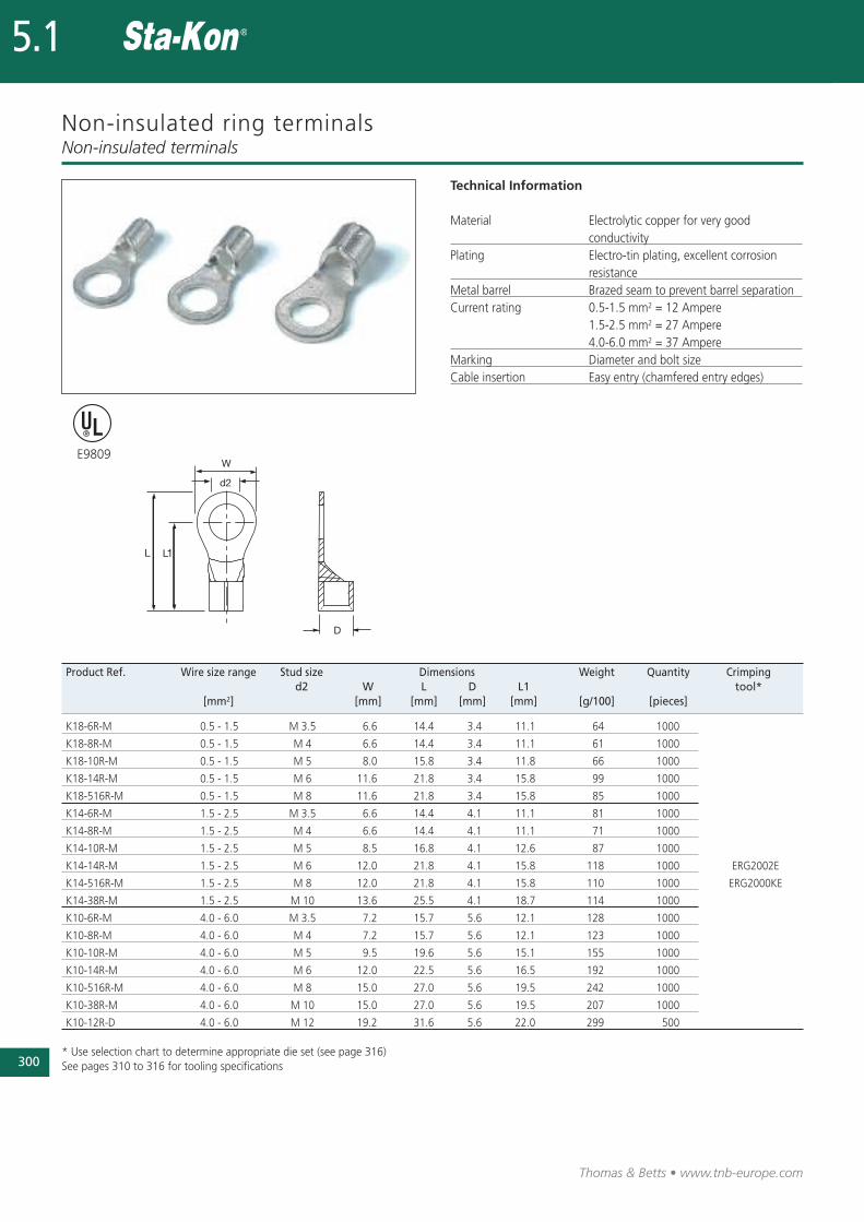
Non-insulated ring terminals
Technical Information
Material Electrolytic copper for very good conductivity
Plating Electro-tin plating, excellent corrosion resistance
Metal barrel Brazed seam to prevent barrel separationCurrent rating 0.5-1.5 mm2 = 12 Ampere
1.5-2.5 mm2 = 27 Ampere4.0-6.0 mm2 = 37 Ampere
Marking Diameter and bolt sizeCable insertion Easy entry (chamfered entry edges)
Non-insulated terminals
Product Ref. Wire size range Stud size Dimensions Weight Quantity Crimping d2 W L D L1 tool*
[mm2] [mm] [mm] [mm] [mm] [g/100] [pieces]
K18-6R-M 0.5 - 1.5 M 3.5 6.6 14.4 3.4 11.1 64 1000
K18-8R-M 0.5 - 1.5 M 4 6.6 14.4 3.4 11.1 61 1000
K18-10R-M 0.5 - 1.5 M 5 8.0 15.8 3.4 11.8 66 1000
K18-14R-M 0.5 - 1.5 M 6 11.6 21.8 3.4 15.8 99 1000
K18-516R-M 0.5 - 1.5 M 8 11.6 21.8 3.4 15.8 85 1000
K14-6R-M 1.5 - 2.5 M 3.5 6.6 14.4 4.1 11.1 81 1000
K14-8R-M 1.5 - 2.5 M 4 6.6 14.4 4.1 11.1 71 1000
K14-10R-M 1.5 - 2.5 M 5 8.5 16.8 4.1 12.6 87 1000
K14-14R-M 1.5 - 2.5 M 6 12.0 21.8 4.1 15.8 118 1000 ERG2002E
K14-516R-M 1.5 - 2.5 M 8 12.0 21.8 4.1 15.8 110 1000 ERG2000KE
K14-38R-M 1.5 - 2.5 M 10 13.6 25.5 4.1 18.7 114 1000
K10-6R-M 4.0 - 6.0 M 3.5 7.2 15.7 5.6 12.1 128 1000
K10-8R-M 4.0 - 6.0 M 4 7.2 15.7 5.6 12.1 123 1000
K10-10R-M 4.0 - 6.0 M 5 9.5 19.6 5.6 15.1 155 1000
K10-14R-M 4.0 - 6.0 M 6 12.0 22.5 5.6 16.5 192 1000
K10-516R-M 4.0 - 6.0 M 8 15.0 27.0 5.6 19.5 242 1000
K10-38R-M 4.0 - 6.0 M 10 15.0 27.0 5.6 19.5 207 1000
K10-12R-D 4.0 - 6.0 M 12 19.2 31.6 5.6 22.0 299 500
* Use selection chart to determine appropriate die set (see page 316)See pages 310 to 316 for tooling specifications
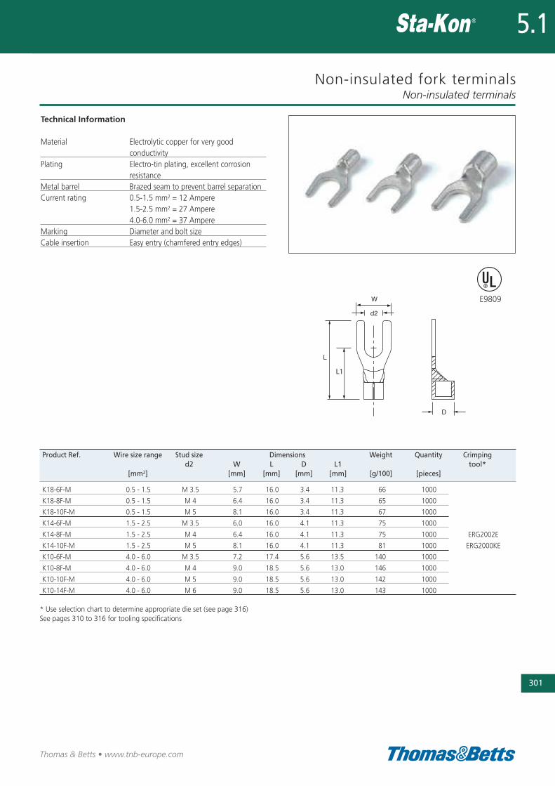
Non-insulated fork terminals
Technical Information
Material Electrolytic copper for very good conductivity
Plating Electro-tin plating, excellent corrosion resistance
Metal barrel Brazed seam to prevent barrel separationCurrent rating 0.5-1.5 mm2 = 12 Ampere
1.5-2.5 mm2 = 27 Ampere4.0-6.0 mm2 = 37 Ampere
Marking Diameter and bolt sizeCable insertion Easy entry (chamfered entry edges)
Non-insulated terminals
301
Thomas & Betts • www.tnb-europe.com
5.1
Product Ref. Wire size range Stud size Dimensions Weight Quantity Crimping d2 W L D L1 tool*
[mm2] [mm] [mm] [mm] [mm] [g/100] [pieces]
K18-6F-M 0.5 - 1.5 M 3.5 5.7 16.0 3.4 11.3 66 1000
K18-8F-M 0.5 - 1.5 M 4 6.4 16.0 3.4 11.3 65 1000
K18-10F-M 0.5 - 1.5 M 5 8.1 16.0 3.4 11.3 67 1000
K14-6F-M 1.5 - 2.5 M 3.5 6.0 16.0 4.1 11.3 75 1000
K14-8F-M 1.5 - 2.5 M 4 6.4 16.0 4.1 11.3 75 1000 ERG2002E
K14-10F-M 1.5 - 2.5 M 5 8.1 16.0 4.1 11.3 81 1000 ERG2000KE
K10-6F-M 4.0 - 6.0 M 3.5 7.2 17.4 5.6 13.5 140 1000
K10-8F-M 4.0 - 6.0 M 4 9.0 18.5 5.6 13.0 146 1000
K10-10F-M 4.0 - 6.0 M 5 9.0 18.5 5.6 13.0 142 1000
K10-14F-M 4.0 - 6.0 M 6 9.0 18.5 5.6 13.0 143 1000
* Use selection chart to determine appropriate die set (see page 316)See pages 310 to 316 for tooling specifications
E9809
302
Thomas & Betts • www.tnb-europe.com
5.1
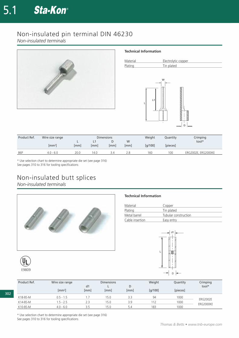
Non-insulated pin terminal DIN 46230
Technical Information
Material Electrolytic copperPlating Tin plated
Non-insulated terminals
Product Ref. Wire size range Dimensions Weight Quantity Crimping L L1 D W tool*
[mm2] [mm] [mm] [mm] [mm] [g/100] [pieces]
B6P 4.0 - 6.0 20.0 14.0 3.4 2.8 160 100 ERG2002E, ERG2000KE
* Use selection chart to determine appropriate die set (see page 316)See pages 310 to 316 for tooling specifications
Product Ref. Wire size range Dimensions Weight Quantity Crimping d1 L D tool*
[mm2] [mm] [mm] [mm] [g/100] [pieces]
K18-BS-M 0.5 - 1.5 1.7 15.0 3.3 94 1000
K14-BS-M 1.5 - 2.5 2.3 15.0 3.9 112 1000ERG2002E
K10-BS-M 4.0 - 6.0 3.5 15.0 5.4 183 1000ERG2000KE
* Use selection chart to determine appropriate die set (see page 316)See pages 310 to 316 for tooling specifications
E9809
Non-insulated butt splicesNon-insulated terminals
Technical Information
Material CopperPlating Tin platedMetal barrel Tubular constructionCable insertion Easy entry
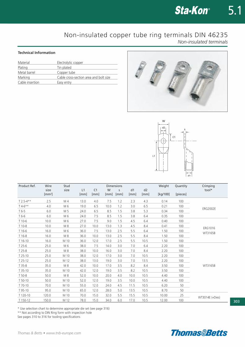
Non-insulated copper tube ring terminals DIN 46235
Technical Information
Material Electrolytic copperPlating Tin platedMetal barrel Copper tubeMarking Cable cross-section area and bolt sizeCable insertion Easy entry
Non-insulated terminals
303
Thomas & Betts • www.tnb-europe.com
5.1
Product Ref. Wire Stud Dimensions Weight Quantity Crimpingsize size L1 C1 W s d1 d2 tool*
[mm2] [mm] [mm] [mm] [mm] [mm] [mm] [kg/100] [pieces]
T 2.5-4** 2.5 M 4 13.0 4.0 7.5 1.2 2.3 4.3 0.14 100
T 4-6** 4.0 M 6 19.0 6.5 10.0 1.2 3.0 6.5 0.21 100ERG2002E
T 6-5 6.0 M 5 24.0 6.5 8.5 1.5 3.8 5.3 0.34 100
T 6-6 6.0 M 6 24.0 7.5 8.5 1.5 3.8 6.4 0.35 100
T 10-6 10.0 M 6 27.0 7.5 9.0 1.5 4.5 6.4 0.40 100
T 10-8 10.0 M 8 27.0 10.0 13.0 1.3 4.5 8.4 0.41 100ERG1016
T 16-6 16.0 M 6 36.0 7.5 13.0 2.5 5.5 6.4 1.50 100WT3165B
T 16-8 16.0 M 8 36.0 10.0 13.0 2.5 5.5 8.4 1.50 100
T 16-10 16.0 M 10 36.0 12.0 17.0 2.5 5.5 10.5 1.50 100
T 25-6 25.0 M 6 38.0 7.5 14.0 3.0 7.0 6.4 2.20 100
T 25-8 25.0 M 8 38.0 10.0 16.0 3.0 7.0 8.4 2.20 100
T 25-10 25.0 M 10 38.0 12.0 17.0 3.0 7.0 10.5 2.20 100
T 25-12 25.0 M 12 38.0 13.0 19.0 3.0 7.0 13.5 2.20 100
T 35-8 35.0 M 8 42.0 10.0 17.0 3.5 8.2 8.4 3.50 100 WT3165B
T 35-10 35.0 M 10 42.0 12.0 19.0 3.5 8.2 10.5 3.50 100
T 50-8 50.0 M 8 52.0 10.0 20.0 4.0 10.0 10.5 4.40 100
T 50-10 50.0 M 10 52.0 12.0 19.0 3.5 10.0 10.5 4.40 100
T 70-10 70.0 M 10 55.0 12.0 24.0 4.5 11.5 10.5 6.20 50
T 95-10 95.0 M 10 65.0 12.0 28.0 5.0 13.5 10.5 8.70 50
T 120-10 120.0 M 10 70.0 15.0 32.0 5.5 15.5 10.5 10.00 25WT3014E (+Dies)
T 150-12 150.0 M 12 78.0 15.0 34.0 6.0 17.0 10.5 12.00 100
* Use selection chart to determine appropriate die set (see page 316)** Not according to DIN Ring form with inspection holeSee pages 310 to 316 for tooling specifications
304
Thomas & Betts • www.tnb-europe.com
5.1
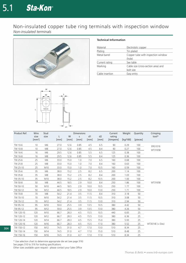
Non-insulated copper tube ring terminals with inspection window
Technical Information
Material Electrolytic copperPlating Tin platedMetal barrel Copper tube with inspection window
(hole)Current rating See tableMarking Cable size (cross-section area) and
bolt size Cable insertion Easy entry
Non-insulated terminals
Product Ref. Wire Stud Dimensions Current Weight Quantity Crimping size size L W s d1 d2 rating tool*
[mm2] [mm] [mm] [mm] [mm] [mm] [Ampere] [kg/100] [pieces]
TW 10-6 10 M6 27.0 12.6 0.85 4.5 6.5 90 0.29 100
TW 10-8 10 M8 27.0 12.6 0.85 4.5 8.4 90 0.27 100ERG1016
TW 16-6 16 M6 29.5 12.6 0.85 5.5 6.5 125 0.38 100WT3165B
TW 16-8 16 M8 29.5 12.6 0.85 5.5 8.4 125 0.36 100
TW 25-6 25 M6 33.0 15.0 1.0 7.0 6.5 160 0.68 100
TW 25-8 25 M8 33.0 15.0 1.0 7.0 8.4 160 0.63 100
TW 25-10 25 M10 33.0 15.0 1.0 7.0 10.5 160 0.59 100
TW 35-6 35 M6 38.0 15.2 2.5 8.2 6.5 200 1.14 100
TW 35-8 35 M8 38.0 15.2 2.5 8.2 8.4 200 1.03 100
TW 35-10 35 M10 38.0 15.2 2.5 8.2 10.5 200 1.00 100
TW 50-8 50 M8 44.5 18.5 2.9 10.0 8.4 250 1.86 100 WT3165B
TW 50-10 50 M10 44.5 18.5 2.9 10.0 10.5 250 1.77 100
TW 50-12 50 M12 44.5 18.5 2.9 10.0 13.0 250 1.71 100
TW 70-8 70 M8 54.2 21.4 3.5 11.5 8.4 310 3.18 50
TW 70-10 70 M10 54.2 21.4 3.5 11.5 10.5 310 3.08 50
TW 70-12 70 M12 54.2 21.4 3.5 11.5 13.0 310 2.94 50
TW 95-10 95 M10 59.0 25.5 3.9 13.5 10.5 380 4.42 50
TW 95-12 95 M12 59.0 25.5 3.9 13.5 13.0 380 4.26 50
TW 120-10 120 M10 66.7 28.3 4.5 15.5 10.5 440 6.83 25
TW 120-12 120 M12 66.7 28.3 4.5 15.5 13.0 380 6.36 25
TW 120-14 120 M14 66.7 28.3 4.5 15.5 15.0 380 5.93 25
TW 120-16 120 M16 66.7 28.3 4.5 15.5 17.0 380 5.52 25 WT3014E (+ Dies)
TW 150-12 150 M12 74.5 31.0 4.7 17.0 13.0 510 8.34 25
TW 150-14 150 M14 74.5 31.0 4.7 17.0 15.0 510 8.48 25
TW 150-16 150 M16 74.5 31.0 4.7 17.0 17.0 510 8.34 25
* Use selection chart to determine appropriate die set (see page 316)See pages 310 to 316 for tooling specificationsOther sizes available upon request - please contact your Sales Office
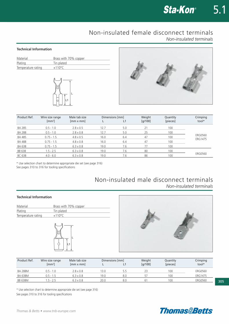
Non-insulated female disconnect terminals
Technical Information
Material Brass with 70% copperPlating Tin platedTemperature rating +110°C
Non-insulated terminals
305
Thomas & Betts • www.tnb-europe.com
5.1
Product Ref. Wire size range Male tab size Dimensions [mm] Weight Quantity Crimping [mm2] [mm x mm] L L1 [g/100] [pieces] tool*
BA 285 0.5 - 1.0 2.8 x 0.5 12.7 5.0 21 100
BA 288 0.5 - 1.0 2.8 x 0.8 12.7 5.0 25 100ERG0560
BA 485 0.75 - 1.5 4.8 x 0.5 16.0 6.4 47 100
BA 488 0.75 - 1.5 4.8 x 0.8 16.0 6.4 47 100ERG1475
BA 638 0.75 - 1.5 6.3 x 0.8 19.0 7.6 77 100
BB 638 1.5 - 2.5 6.3 x 0.8 19.0 7.6 80 100ERG0560
BC 638 4.0 - 6.0 6.3 x 0.8 19.0 7.6 86 100
* Use selection chart to determine appropriate die set (see page 316)See pages 310 to 316 for tooling specifications
Product Ref. Wire size range Male tab size Dimensions [mm] Weight Quantity Crimping [mm2] [mm x mm] L L1 [g/100] [pieces] tool*
BA 288M 0.5 - 1.0 2.8 x 0.8 13.0 5.5 23 100 ERG0560
BA 638M 0.5 - 1.5 6.3 x 0.8 19.0 8.0 57 100 ERG1475
BB 638M 1.5 - 2.5 6.3 x 0.8 20.0 8.0 61 100 ERG0560
* Use selection chart to determine appropriate die set (see page 316)
See pages 310 to 316 for tooling specifications
Non-insulated male disconnect terminalsNon-insulated terminals
Technical Information
Material Brass with 70% copperPlating Tin platedTemperature rating +110°C
306
Thomas & Betts • www.tnb-europe.com
5.1
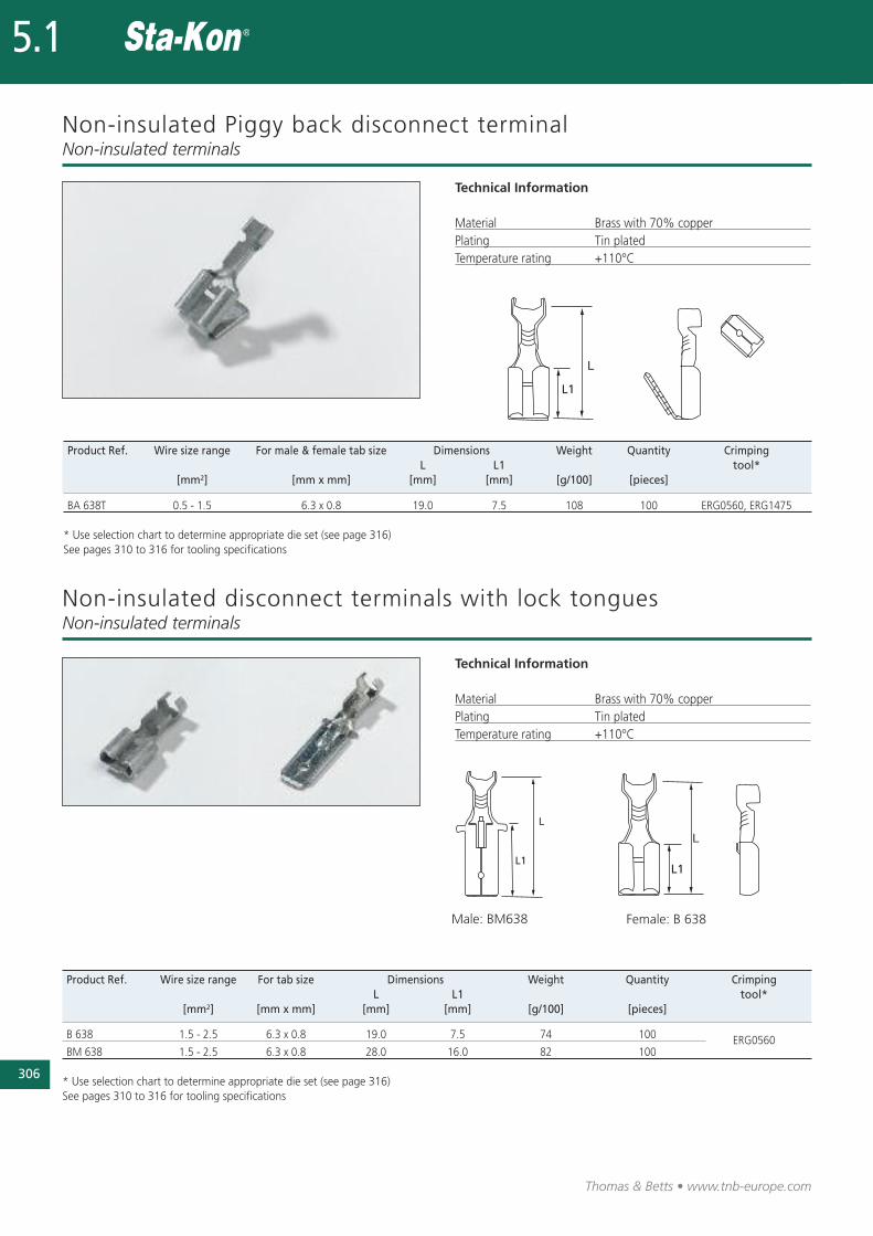
Non-insulated Piggy back disconnect terminal
Technical Information
Material Brass with 70% copperPlating Tin platedTemperature rating +110°C
Non-insulated terminals
Product Ref. Wire size range For male & female tab size Dimensions Weight Quantity Crimping L L1 tool*
[mm2] [mm x mm] [mm] [mm] [g/100] [pieces]
BA 638T 0.5 - 1.5 6.3 x 0.8 19.0 7.5 108 100 ERG0560, ERG1475
* Use selection chart to determine appropriate die set (see page 316)See pages 310 to 316 for tooling specifications
Product Ref. Wire size range For tab size Dimensions Weight Quantity CrimpingL L1 tool*
[mm2] [mm x mm] [mm] [mm] [g/100] [pieces]
B 638 1.5 - 2.5 6.3 x 0.8 19.0 7.5 74 100 ERG0560BM 638 1.5 - 2.5 6.3 x 0.8 28.0 16.0 82 100
* Use selection chart to determine appropriate die set (see page 316)See pages 310 to 316 for tooling specifications
Male: BM638 Female: B 638
Non-insulated disconnect terminals with lock tonguesNon-insulated terminals
Technical Information
Material Brass with 70% copperPlating Tin platedTemperature rating +110°C
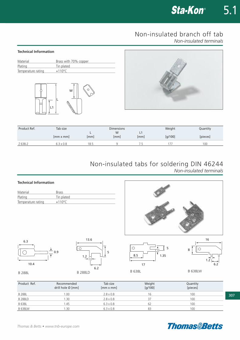
Non-insulated branch off tab
Technical Information
Material Brass with 70% copperPlating Tin platedTemperature rating +110°C
Non-insulated terminals
307
Thomas & Betts • www.tnb-europe.com
5.1
Product Ref. Tab size Dimensions Weight QuantityL W L1
[mm x mm] [mm] [mm] [mm] [g/100] [pieces]
Z 638-2 6.3 x 0.8 18.5 9 7.5 177 100
0.9
10.46.2
13.6
51.2
17
8.5 1.35
5
16
8
6.21.2
6.3
Product Ref. Recommended Tab size Weight Quantity drill hole Ø [mm] [mm x mm] [g/100] [pieces]
B 288L 1.00 2.8 x 0.8 16 100
B 288LD 1.30 2.8 x 0.8 37 100
B 638L 1.45 6.3 x 0.8 62 100
B 638LW 1.30 6.3 x 0.8 83 100
Non-insulated tabs for soldering DIN 46244Non-insulated terminals
Technical Information
Material BrassPlating Tin platedTemperature rating +110°C
B 288L B 288LD B 638L B 638LW
308
Thomas & Betts • www.tnb-europe.com
5.1
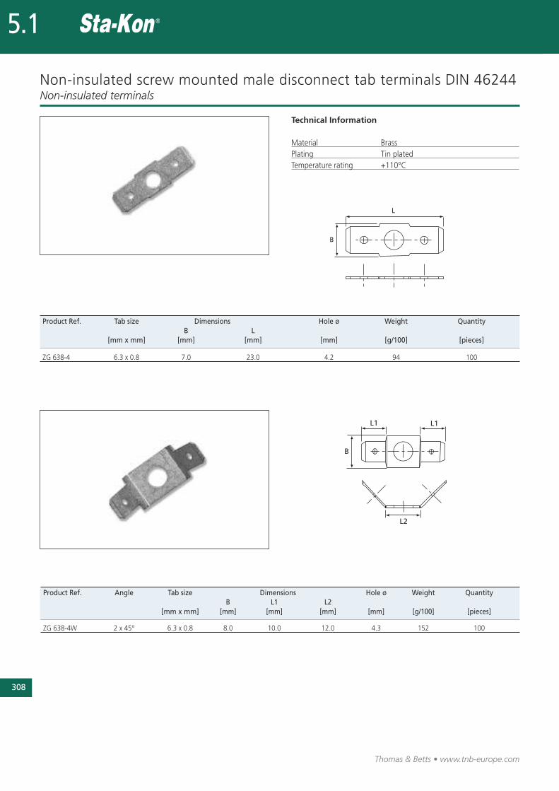
Non-insulated screw mounted male disconnect tab terminals DIN 46244
Technical Information
Material BrassPlating Tin platedTemperature rating +110°C
Non-insulated terminals
Product Ref. Tab size Dimensions Hole ø Weight QuantityB L
[mm x mm] [mm] [mm] [mm] [g/100] [pieces]
ZG 638-4 6.3 x 0.8 7.0 23.0 4.2 94 100
Product Ref. Angle Tab size Dimensions Hole ø Weight QuantityB L1 L2
[mm x mm] [mm] [mm] [mm] [mm] [g/100] [pieces]
ZG 638-4W 2 x 45° 6.3 x 0.8 8.0 10.0 12.0 4.3 152 100
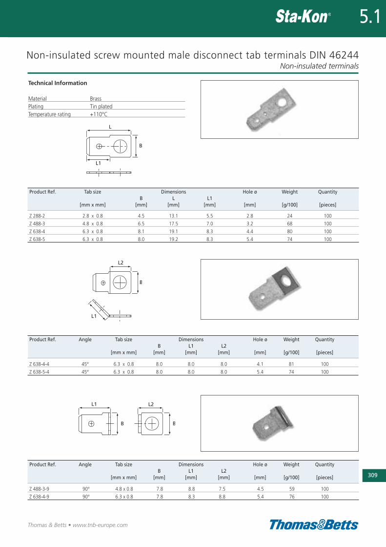
Non-insulated screw mounted male disconnect tab terminals DIN 46244
Technical Information
Material BrassPlating Tin platedTemperature rating +110°C
Non-insulated terminals
309
Thomas & Betts • www.tnb-europe.com
5.1
Product Ref. Tab size Dimensions Hole ø Weight QuantityB L L1
[mm x mm] [mm] [mm] [mm] [mm] [g/100] [pieces]
Z 288-2 2.8 x 0.8 4.5 13.1 5.5 2.8 24 100
Z 488-3 4.8 x 0.8 6.5 17.5 7.0 3.2 68 100
Z 638-4 6.3 x 0.8 8.1 19.1 8.3 4.4 80 100
Z 638-5 6.3 x 0.8 8.0 19.2 8.3 5.4 74 100
Product Ref. Angle Tab size Dimensions Hole ø Weight QuantityB L1 L2
[mm x mm] [mm] [mm] [mm] [mm] [g/100] [pieces]
Z 638-4-4 45° 6.3 x 0.8 8.0 8.0 8.0 4.1 81 100
Z 638-5-4 45° 6.3 x 0.8 8.0 8.0 8.0 5.4 74 100
Product Ref. Angle Tab size Dimensions Hole ø Weight QuantityB L1 L2
[mm x mm] [mm] [mm] [mm] [mm] [g/100] [pieces]
Z 488-3-9 90° 4.8 x 0.8 7.8 8.8 7.5 4.5 59 100
Z 638-4-9 90° 6.3 x 0.8 7.8 8.3 8.8 5.4 76 100
Thomas & Betts • www.tnb-europe.com
Overview
An extensive range of tooling is available, suiting a variety ofrequirements, to crimp the following terminals:• Insulated terminals and bootlace ferrules• Non-insulated terminals• Copper tube terminals
Crimping tools
5.1
310
Plier type crimping toolsCrimping tools
Different types of tooling are offered, depending on volume andapplication:• Plier type hand tools for occasional applications (“Do-It-Yourself”users)
• Standard hand tooling for low to medium volume applications• Ergonomic hand tooling for low to medium volume applications,where high, repeatable quality is essential
• Large hand tools• Hydraulic tooling for heavy-duty applications
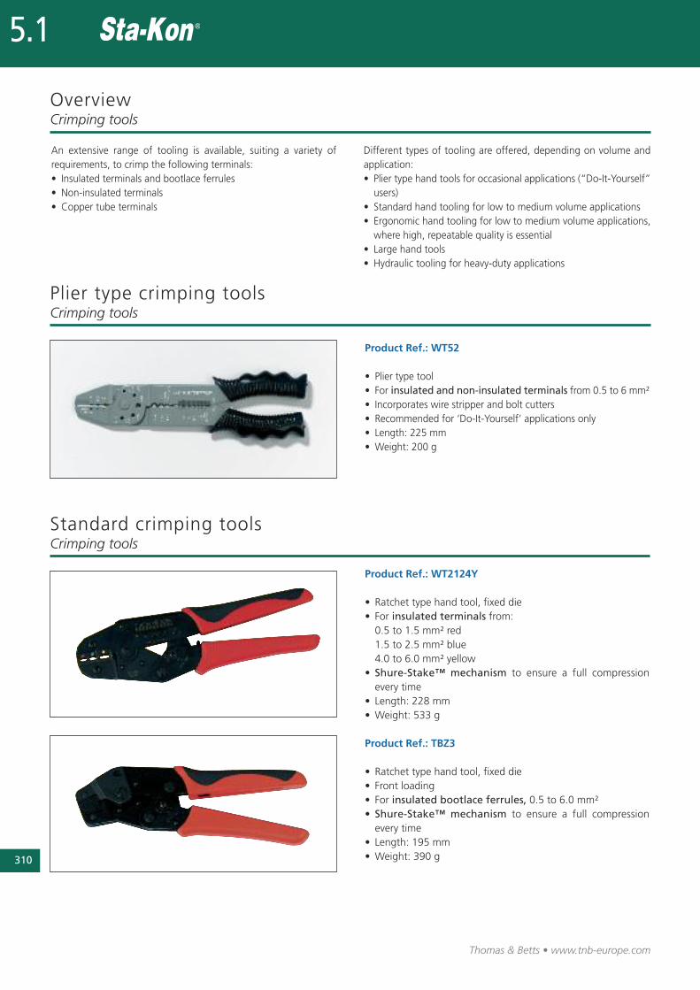
Standard crimping tools
Product Ref.: WT2124Y
• Ratchet type hand tool, fixed die• For insulated terminals from:0.5 to 1.5 mm² red1.5 to 2.5 mm² blue4.0 to 6.0 mm² yellow
• Shure-Stake™ mechanism to ensure a full compressionevery time
• Length: 228 mm• Weight: 533 g
Crimping tools
Product Ref.: TBZ3
• Ratchet type hand tool, fixed die• Front loading• For insulated bootlace ferrules, 0.5 to 6.0 mm²• Shure-Stake™ mechanism to ensure a full compressionevery time
• Length: 195 mm• Weight: 390 g
Product Ref.: WT52
• Plier type tool• For insulated and non-insulated terminals from 0.5 to 6 mm²• Incorporates wire stripper and bolt cutters• Recommended for ‘Do-It-Yourself’ applications only• Length: 225 mm• Weight: 200 g
Ergonomic hand tools
• Ergonomic ratchet style hand tools used for installing insulatedand non-insulated terminals
• Specially designed ergonomic handles distribute the crimpingforce more evenly across the user’s hands. This helps to reducethe risk of Carpal Tunnel Syndrome, the cause of almost one intwo industrial injuries
• Ratchet design greatly reduces handle forces over conventionalhand tools and incorporates the Shure-Stake™ mechanism whichensures a full crimp cycle every time
Crimping tools
Thomas & Betts • www.tnb-europe.com
5.1
311
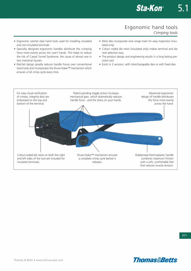
For easy visual verificationof crimps, integrity dots are embossed on the top andbottom of the terminal.
Patent-pending toggle action increasesmechanical gain, which dramatically reduceshandle force - and the stress on your hands.
Advanced ergonomicdesign of handle distributes
the force more evenlyacross the hand.
Colour-coded die nests on both the rightand left sides of the tool are included forinsulated terminals.
Shure-Stake™ mechanism ensuresa complete crimp cycle before it
releases.
Rubberised thermoplastic handlecombines maximum frictionwith a soft, comfortable feel that reduces muscle tension.
• Most dies incorporate wire range mark for easy inspection (insu-lated only)
• Colour coded die nests (insulated only) makes terminal and dienest selection easy
• The product design and engineering results in a long lasting pre-cision tool
• Exists in 2 versions: with interchangeable dies or with fixed dies
312
Thomas & Betts • www.tnb-europe.com
5.1
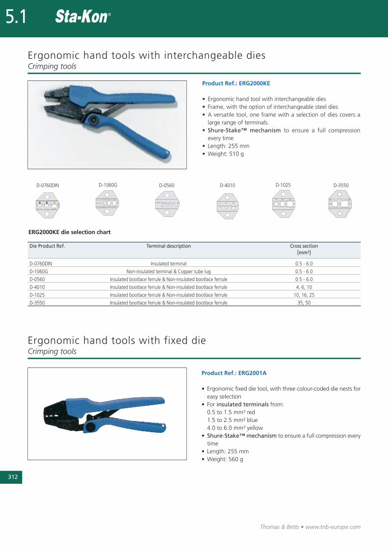
Ergonomic hand tools with interchangeable dies
Product Ref.: ERG2000KE
• Ergonomic hand tool with interchangeable dies• Frame, with the option of interchangeable steel dies• A versatile tool, one frame with a selection of dies covers alarge range of terminals.
• Shure-Stake™ mechanism to ensure a full compressionevery time
• Length: 255 mm• Weight: 510 g
Crimping tools
Die Product Ref. Terminal description Cross section [mm2]
D-0760DIN Insulated terminal 0.5 - 6.0
D-1060G Non-insulated terminal & Copper tube lug 0.5 - 6.0
D-0560 Insulated bootlace ferrule & Non-insulated bootlace ferrule 0.5 - 6.0
D-4010 Insulated bootlace ferrule & Non-insulated bootlace ferrule 4, 6, 10
D-1025 Insulated bootlace ferrule & Non-insulated bootlace ferrule 10, 16, 25
D-3550 Insulated bootlace ferrule & Non-insulated bootlace ferrule 35, 50
ERG2000KE die selection chart
D-0760DIN D-1060G D-0560 D-4010 D-1025 D-3550
Ergonomic hand tools with fixed dieCrimping tools
Product Ref.: ERG2001A
• Ergonomic fixed die tool, with three colour-coded die nests foreasy selection
• For insulated terminals from:0.5 to 1.5 mm² red1.5 to 2.5 mm² blue4.0 to 6.0 mm² yellow
• Shure-Stake™ mechanism to ensure a full compression everytime
• Length: 255 mm• Weight: 560 g
Ergonomic hand tools with fixed die
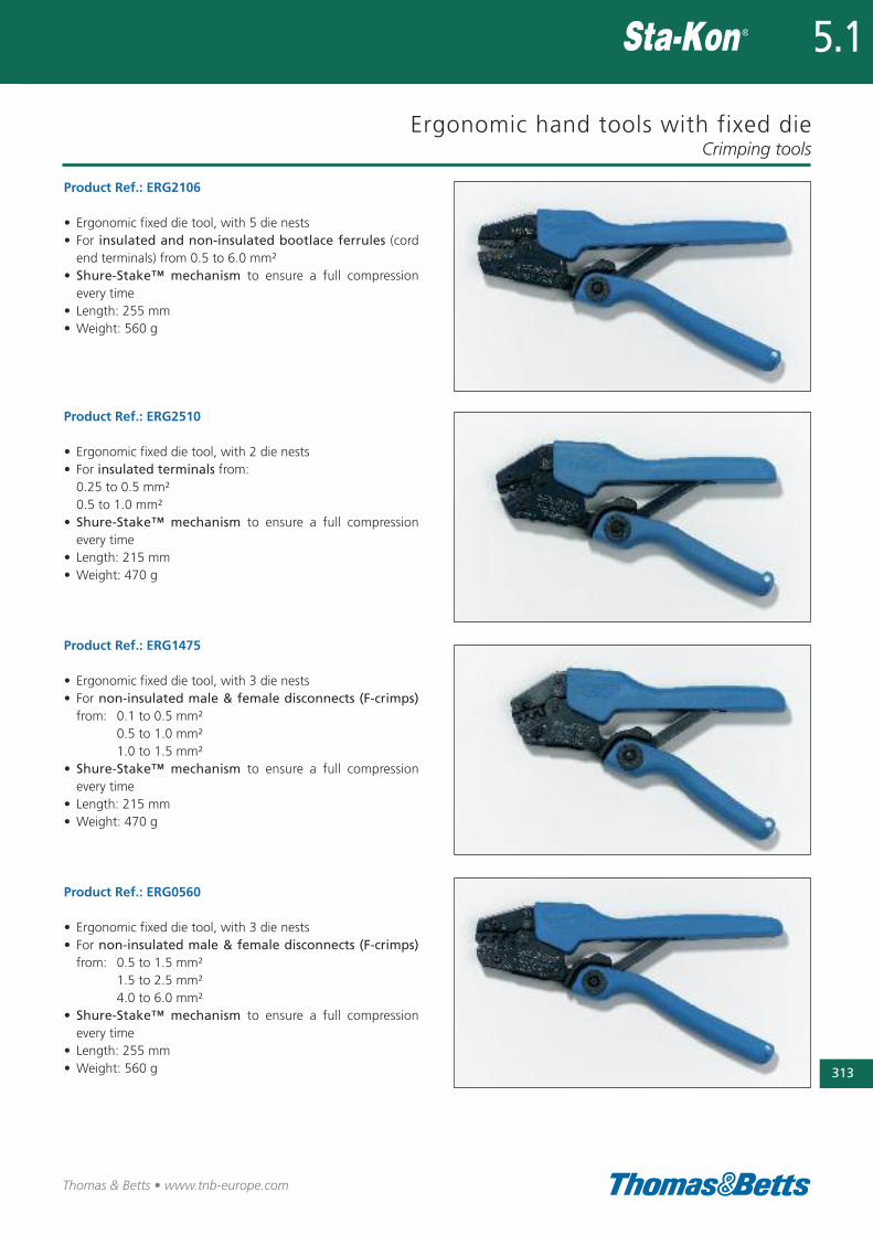
Product Ref.: ERG2106
• Ergonomic fixed die tool, with 5 die nests• For insulated and non-insulated bootlace ferrules (cordend terminals) from 0.5 to 6.0 mm²
• Shure-Stake™ mechanism to ensure a full compressionevery time
• Length: 255 mm• Weight: 560 g
Product Ref.: ERG2510
• Ergonomic fixed die tool, with 2 die nests• For insulated terminals from:0.25 to 0.5 mm²0.5 to 1.0 mm²
• Shure-Stake™ mechanism to ensure a full compressionevery time
• Length: 215 mm• Weight: 470 g
Product Ref.: ERG1475
• Ergonomic fixed die tool, with 3 die nests• For non-insulated male & female disconnects (F-crimps)from: 0.1 to 0.5 mm²
0.5 to 1.0 mm²1.0 to 1.5 mm²
• Shure-Stake™ mechanism to ensure a full compressionevery time
• Length: 215 mm• Weight: 470 g
Product Ref.: ERG0560
• Ergonomic fixed die tool, with 3 die nests• For non-insulated male & female disconnects (F-crimps)from: 0.5 to 1.5 mm²
1.5 to 2.5 mm²4.0 to 6.0 mm²
• Shure-Stake™ mechanism to ensure a full compressionevery time
• Length: 255 mm• Weight: 560 g
Crimping tools
313
Thomas & Betts • www.tnb-europe.com
5.1
314
Thomas & Betts • www.tnb-europe.com
5.1
Ergonomic hand tools with fixed die
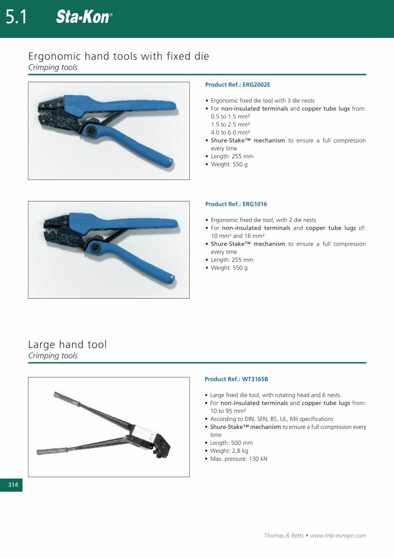
Product Ref.: ERG2002E
• Ergonomic fixed die tool with 3 die nests• For non-insulated terminals and copper tube lugs from:0.5 to 1.5 mm²1.5 to 2.5 mm²4.0 to 6.0 mm²
• Shure-Stake™ mechanism to ensure a full compressionevery time
• Length: 255 mm• Weight: 550 g
Product Ref.: ERG1016
• Ergonomic fixed die tool, with 2 die nests• For non-insulated terminals and copper tube lugs of:10 mm² and 16 mm²
• Shure-Stake™ mechanism to ensure a full compressionevery time
• Length: 255 mm• Weight: 550 g
Crimping tools
Product Ref.: WT3165B
• Large fixed die tool, with rotating head and 6 nests• For non-insulated terminals and copper tube lugs from:10 to 95 mm²
• According to DIN, SEN, BS, UL, Mil specifications• Shure-Stake™ mechanism to ensure a full compression everytime
• Length: 500 mm• Weight: 2,8 kg• Max. pressure: 130 kN
Large hand toolCrimping tools
Hydraulic toolsCrimping tools
315
Thomas & Betts • www.tnb-europe.com
5.1
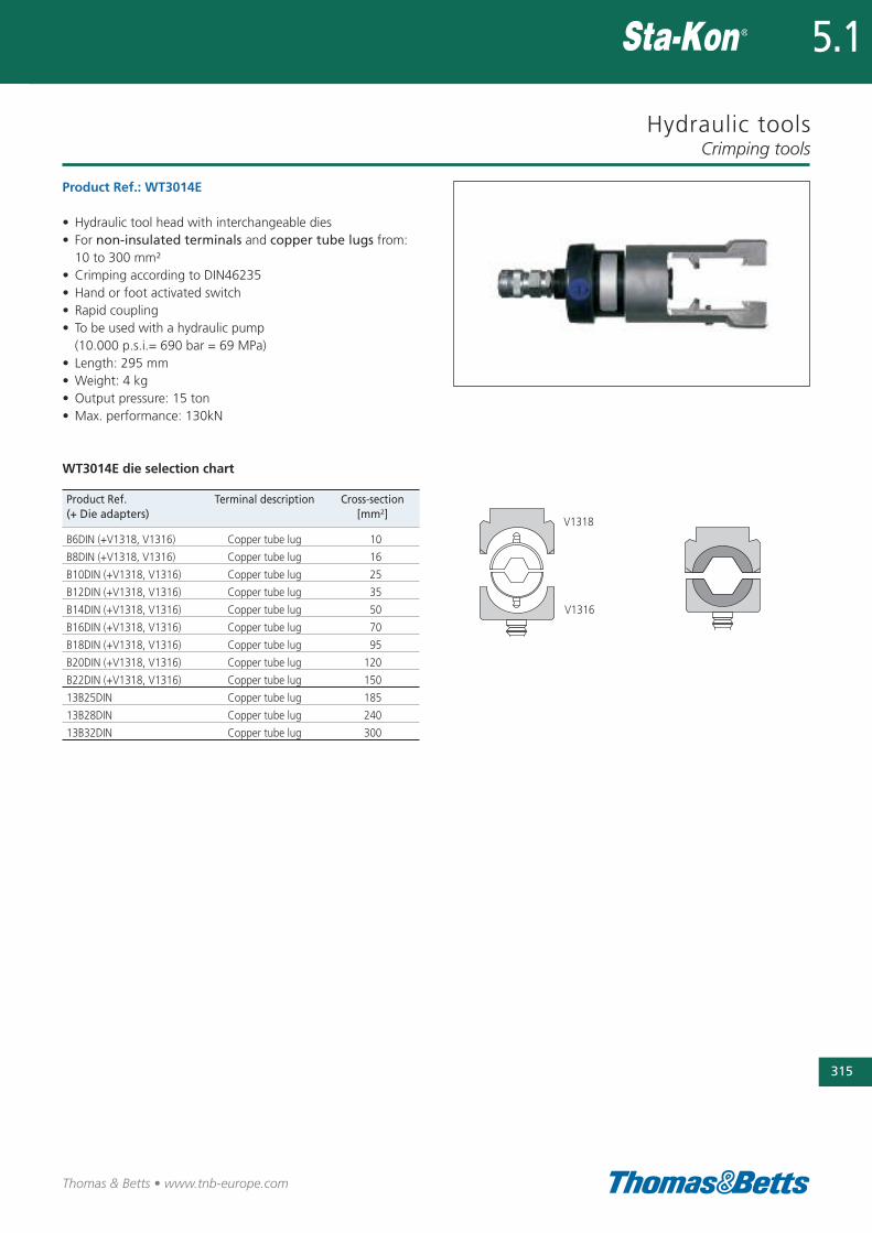
V1318
V1316
Product Ref.: WT3014E
• Hydraulic tool head with interchangeable dies• For non-insulated terminals and copper tube lugs from:10 to 300 mm²
• Crimping according to DIN46235• Hand or foot activated switch• Rapid coupling• To be used with a hydraulic pump (10.000 p.s.i.= 690 bar = 69 MPa)
• Length: 295 mm• Weight: 4 kg• Output pressure: 15 ton• Max. performance: 130kN
WT3014E die selection chart
Product Ref. Terminal description Cross-section(+ Die adapters) [mm2]
B6DIN (+V1318, V1316) Copper tube lug 10
B8DIN (+V1318, V1316) Copper tube lug 16
B10DIN (+V1318, V1316) Copper tube lug 25
B12DIN (+V1318, V1316) Copper tube lug 35
B14DIN (+V1318, V1316) Copper tube lug 50
B16DIN (+V1318, V1316) Copper tube lug 70
B18DIN (+V1318, V1316) Copper tube lug 95
B20DIN (+V1318, V1316) Copper tube lug 120
B22DIN (+V1318, V1316) Copper tube lug 150
13B25DIN Copper tube lug 185
13B28DIN Copper tube lug 240
13B32DIN Copper tube lug 300
316
Thomas & Betts • www.tnb-europe.com
5.1
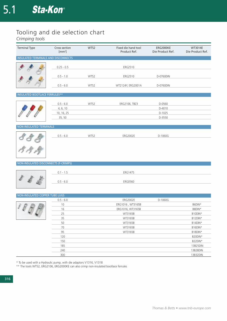
Tooling and die selection chartCrimping tools
Terminal Type Cross section WT52 Fixed die hand tool ERG2000KE WT3014E[mm2] Product Ref. Die Product Ref. Die Product Ref.
INSULATED TERMINALS AND DISCONNECTS
0.25 - 0.5 ERG2510
0.5 - 1.0 WT52 ERG2510 D-0760DIN
0.5 - 6.0 WT52 WT2124Y, ERG2001A D-0760DIN
INSULATED BOOTLACE FERRULES**
0.5 - 6.0 WT52 ERG2106, TBZ3 D-0560
4, 6, 10 D-4010
10, 16, 25 D-1025
35, 50 D-3550
NON-INSULATED TERMINALS
0.5 - 6.0 WT52 ERG2002E D-1060G
NON-INSULATED DISCONNECTS (F-CRIMPS)
0.1 - 1.5 ERG1475
0.5 - 6.0 ERG0560
NON-INSULATED COPPER TUBE LUGS
0.5 - 6.0 ERG2002E D-1060G
10 ERG1016 , WT3165B B6DIN*
16 ERG1016, WT3165B B8DIN*
25 WT3165B B10DIN*
35 WT3165B B12DIN*
50 WT3165B B14DIN*
70 WT3165B B16DIN*
95 WT3165B B18DIN*
120 B20DIN*
150 B22DIN*
185 13B25DIN
240 13B28DIN
300 13B32DIN
* To be used with a Hydraulic pump, with die adaptors V1316, V1318** The tools WT52, ERG2106, ERG2000KE can also crimp non-insulated bootlace ferrules
Overview
Thomas & Betts offer a wide variety of specialty tools used mostcommonly by electricians. Easy to use, they are convenient to allkind of job, whether it is new installation or maintenance.Designed for the professionals, all the stripping and cutting toolsfrom Thomas & Betts are manufactured from top quality materialsto assure durability and a long usable life. Single purpose and com-bination function designs are included.
Stripping & cutting tools
317
Thomas & Betts • www.tnb-europe.com
5.1
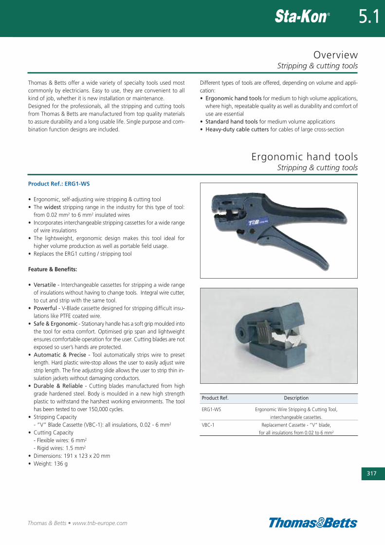
Product Ref.: ERG1-WS
• Ergonomic, self-adjusting wire stripping & cutting tool• The widest stripping range in the industry for this type of tool:from 0.02 mm2 to 6 mm2 insulated wires
• Incorporates interchangeable stripping cassettes for a wide rangeof wire insulations
• The lightweight, ergonomic design makes this tool ideal forhigher volume production as well as portable field usage.
• Replaces the ERG1 cutting / stripping tool
Feature & Benefits:
• Versatile - Interchangeable cassettes for stripping a wide rangeof insulations without having to change tools. Integral wire cutter,to cut and strip with the same tool.
• Powerful - V-Blade cassette designed for stripping difficult insu-lations like PTFE coated wire.
• Safe & Ergonomic - Stationary handle has a soft grip moulded intothe tool for extra comfort. Optimised grip span and lightweightensures comfortable operation for the user. Cutting blades are notexposed so user’s hands are protected.
• Automatic & Precise - Tool automatically strips wire to presetlength. Hard plastic wire-stop allows the user to easily adjust wirestrip length. The fine adjusting slide allows the user to strip thin in-sulation jackets without damaging conductors.
• Durable & Reliable - Cutting blades manufactured from highgrade hardened steel. Body is moulded in a new high strengthplastic to withstand the harshest working environments. The toolhas been tested to over 150,000 cycles.
• Stripping Capacity - “V” Blade Cassette (VBC-1): all insulations, 0.02 - 6 mm2
• Cutting Capacity- Flexible wires: 6 mm2
- Rigid wires: 1.5 mm2
• Dimensions: 191 x 123 x 20 mm• Weight: 136 g
Ergonomic hand toolsStripping & cutting tools
Different types of tools are offered, depending on volume and appli-cation:• Ergonomic hand tools for medium to high volume applications,where high, repeatable quality as well as durability and comfort ofuse are essential
• Standard hand tools for medium volume applications• Heavy-duty cable cutters for cables of large cross-section
Product Ref. Description
ERG1-WS Ergonomic Wire Stripping & Cutting Tool,
interchangeable cassettes.
VBC-1 Replacement Cassette - “V” blade,
for all insulations from 0.02 to 6 mm2
318
Thomas & Betts • www.tnb-europe.com
5.1
Standard hand tools
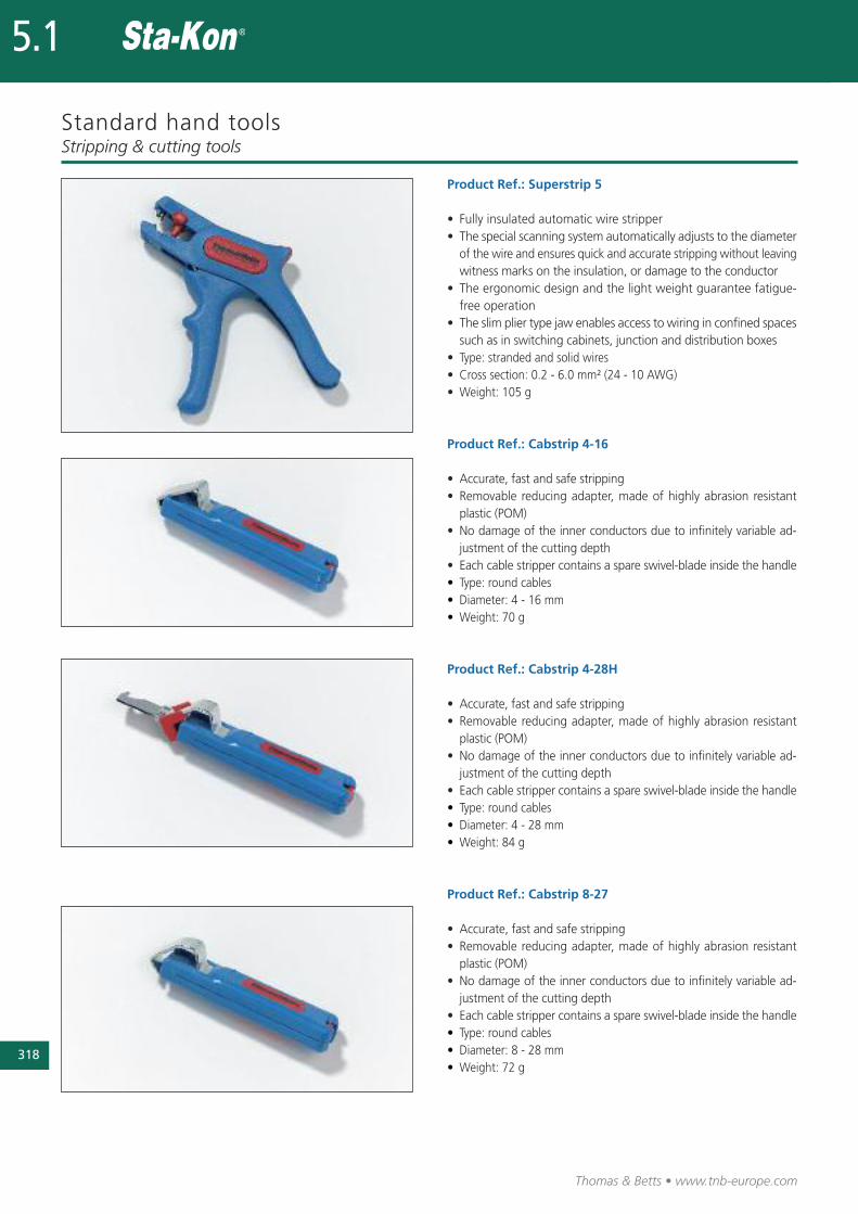
Product Ref.: Superstrip 5
• Fully insulated automatic wire stripper• The special scanning system automatically adjusts to the dia me ter
of the wire and ensures quick and accurate stripping without leavingwitness marks on the insulation, or damage to the conductor
• The ergonomic design and the light weight guarantee fatigue-free operation
• The slim plier type jaw enables access to wiring in confined spacessuch as in switching cabinets, junction and distribution boxes
• Type: stranded and solid wires• Cross section: 0.2 - 6.0 mm² (24 - 10 AWG)• Weight: 105 g
Product Ref.: Cabstrip 4-16
• Accurate, fast and safe stripping• Removable reducing adapter, made of highly abrasion resistantplastic (POM)
• No damage of the inner conductors due to infinitely variable ad-justment of the cutting depth
• Each cable stripper contains a spare swivel-blade inside the handle• Type: round cables• Diameter: 4 - 16 mm • Weight: 70 g
Product Ref.: Cabstrip 4-28H
• Accurate, fast and safe stripping• Removable reducing adapter, made of highly abrasion resistantplastic (POM)
• No damage of the inner conductors due to infinitely variable ad-justment of the cutting depth
• Each cable stripper contains a spare swivel-blade inside the handle• Type: round cables• Diameter: 4 - 28 mm• Weight: 84 g
Product Ref.: Cabstrip 8-27
• Accurate, fast and safe stripping• Removable reducing adapter, made of highly abrasion resistantplastic (POM)
• No damage of the inner conductors due to infinitely variable ad-justment of the cutting depth
• Each cable stripper contains a spare swivel-blade inside the handle• Type: round cables• Diameter: 8 - 28 mm• Weight: 72 g
Stripping & cutting tools
Standard hand tools
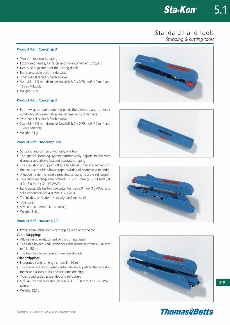
Product Ref.: Coaxstrip 3
• Two or three level stripping• Ergonomic handle, for faster and more convenient stripping• Needs no adjustment of the cutting depth• Easily accessible built-in side cutter• Type: coaxial cables & flexible cable• Size: 4.8 - 7.5 mm diameter (coaxial) & 3 x 0.75 mm², 10 mm² and
16 mm² (flexible)• Weight: 55 g
Product Ref.: Coaxstrip 2
• In a few quick operations the braid, the dielectric and the innerconductor of coaxial cables are set free without damage
• Type: coaxial cables & flexible cable• Size: 4.8 - 7.5 mm diameter (coaxial) & 3 x 0.75 mm², 10 mm² and
16 mm² (flexible)• Weight: 24 g
Product Ref.: Duocrimp 300
• Stripping and crimping with only one tool• The special scanning system automatically adjusts to the wirediameter and allows fast and accurate stripping
• The insulation is stripped off at a length of 5 mm and remains onthe conductor (this allows proper twisting of stranded wire ends)
• A gauge inside the handle simplifies stripping to a pre-set length• Two crimping ranges are offered: 0.5 - 2.5 mm² (20 - 13 AWG) &4.0 - 6.0 mm² (12 - 10 AWG)
• Easily accessible built-in side cutter for max 6.0 mm² (10 AWG) andsolid conductors for 4.0 mm² (12 AWG)
• The blades are made of specially hardened steel• Type: wires • Size: 0.5 - 6.0 mm² (20 - 10 AWG)• Weight: 116 g
Product Ref.: Duostrip 200
• Professional cable and wire stripping with only one toolCable Stripping:• Allows variable adjustment of the cutting depth• The cable holder is adjustable for cable diameters from 4 - 16 mmor 16 - 28 mm
• The tool handle contains a spare swivel-bladeWire Stripping:• Integrated scale for lengths from 8 - 20 mm• The special scanning system automatically adjusts to the wire dia -me ter and allows quick and accurate stripping
• Type: round cables & stranded and solid wires• Size: 4 - 28 mm diameter (cables) & 0.5 - 6.0 mm² (20 - 10 AWG)
(wires)• Weight: 123 g
Stripping & cutting tools
319
Thomas & Betts • www.tnb-europe.com
5.1

320
Thomas & Betts • www.tnb-europe.com
5.1
Standard hand tools
Product Ref.: Duostrip 150
• Fully insulated automatic wire stripper with integrated scale forlengths from 8 - 20 mm
• The special scanning system automatically adjusts to the wirediameter and allows fast and accurate stripping
• Comes with an easily accessible built-in side cutter for strandedconductors up to 6.0 mm2 (10 AWG) and solid conductors up to4.0 mm² (12 AWG)
• Type: stranded and solid wires• Size: 0.5 - 6.0 mm² (20 - 10 AWG)• Weight: 110 g
Product Ref.: Multistrip 400
• Cable and wire stripper• Allows circular and longitudinal stripping as well as flush strip-ping in hard-to-reach areas (e.g. ceilings and walls, junction anddistribution boxes, switch cabinets)
• Easily accessible built-in side cutter for flexible conductors of maxi-mum 6.0 mm2 (10 AWG) and solid conductors of maximum 4.0 mm2
(12 AWG)• Type: round cables & stranded and solid wires• Size: 8 - 13 mm diameter (cables) & 0.5 mm², 4.0 mm² and 6.0 mm²
(20 - 10 AWG) (wires)• Weight: 78 g
Product Ref.: Cabstrip 13
• This tool has been specially designed to remove the outer insula-tion jacket of round cables in confined spaces
• Enables flush stripping in ceiling and wall areas, junction anddistribution boxes, switch, cabinets, etc.
• The ergonomic tool design provides for a sure grip and comfort • In only one operation, the cable sheath is cut and pulled off. Noadjustment of cutting depth is necessary
• Type: round cables• Size: 8 - 13 mm diameter• Weight: 42 g
Stripping & cutting tools
Heavy-duty cable cuttersStripping & cutting tools
321
Thomas & Betts • www.tnb-europe.com
5.1
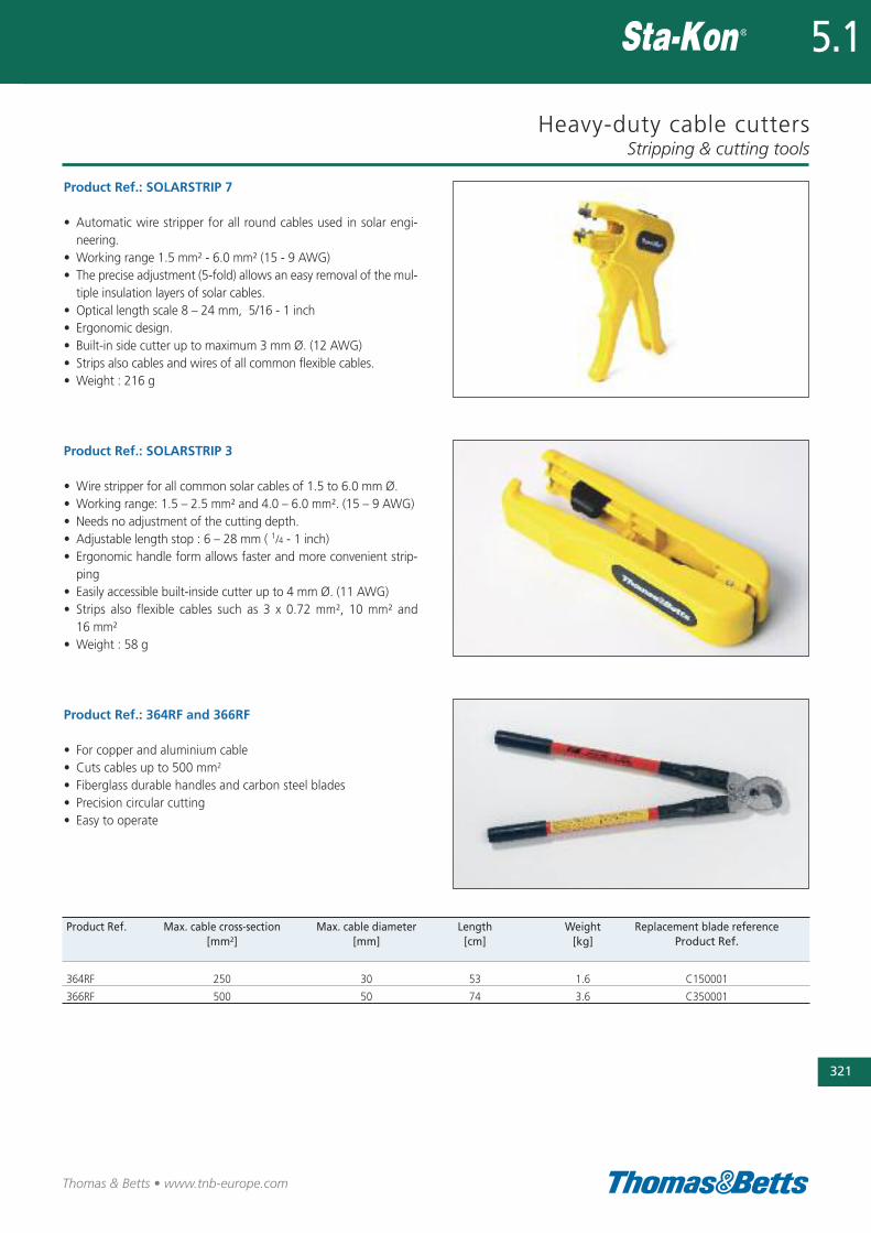
Product Ref.: 364RF and 366RF
• For copper and aluminium cable • Cuts cables up to 500 mm2
• Fiberglass durable handles and carbon steel blades• Precision circular cutting• Easy to operate
Product Ref. Max. cable cross-section Max. cable diameter Length Weight Replacement blade reference[mm2] [mm] [cm] [kg] Product Ref.
364RF 250 30 53 1.6 C150001
366RF 500 50 74 3.6 C350001
Product Ref.: SOLARSTRIP 7
• Automatic wire stripper for all round cables used in solar engi-neering.
• Working range 1.5 mm² - 6.0 mm² (15 - 9 AWG)• The precise adjustment (5-fold) allows an easy removal of the mul-tiple insulation layers of solar cables.
• Optical length scale 8 – 24 mm, 5/16 - 1 inch• Ergonomic design.• Built-in side cutter up to maximum 3 mm Ø. (12 AWG)• Strips also cables and wires of all common flexible cables. • Weight : 216 g
Product Ref.: SOLARSTRIP 3
• Wire stripper for all common solar cables of 1.5 to 6.0 mm Ø.• Working range: 1.5 – 2.5 mm² and 4.0 – 6.0 mm². (15 – 9 AWG)• Needs no adjustment of the cutting depth. • Adjustable length stop : 6 – 28 mm ( 1/4 - 1 inch)• Ergonomic handle form allows faster and more convenient strip-ping
• Easily accessible built-inside cutter up to 4 mm Ø. (11 AWG)• Strips also flexible cables such as 3 x 0.72 mm², 10 mm² and16 mm²
• Weight : 58 g

Thomas & Betts • www.tnb-europe.com
5.2
Color-Keyed®
Solder less compress ionconnectors for power cables
322
Thomas & Betts • www.tnb-europe.com
5.2
TERMINATION SYSTEMS
5.1 STA-KON® - CRIMP TERMINALS 278
5.2 COLOR-KEYED® - POWER CABLE CONNECTORS 322
Connectors for 600 V to 25 kV applications 326
Overview 326
Splices 327
Lugs 329
Crimping tools 331
Standard hand tool 331
Large hand tools 331
Hydraulic tools 333
Smart tools 334
Tool and die selection chart 335
5.3 DRAGON TOOTH® - MAGNET WIRE TERMINALS 336
5.4 SHIELD-KON® - SHIELDED CABLE CONNECTORS 368
323

Thomas & Betts • www.tnb-europe.com
Color-Keyed®
Solder less compress ionconnectors for power cables
The better method to install sorderless compression
connectors on power cables.
Designed to provide a tight degree of reliability in electrical
wiring, this method allows electrical workers to make
installations with little effort and considerable savings in
time.
A simple installation method in just three steps:
• First, the appropriate connector is chosen for the conductor
size
• Next, the proper installing die is selected by matching the die
colour to the connector colour
• Last, the die is installed in the tool, and the connector is com-
pressed
324
5.2

325
Thomas & Betts • www.tnb-europe.com
Wide range of copper tube lugs,
splices and installation tools
Color-Keyed®: special lugs for special applications
Thomas & Betts can solve your difficult wire bending and termi-
nating problems in confined power distribution panels, switchgear
and motor control enclosures. We have the design and production
capability to deliver exactly the type of lug you need, shaped the
way you need.
• Straight, 45° and 90° angle
• Stacking or non-stacking
• Narrow tongue or standard
• Tin, silver, lead, nickel plated Thomas & Betts offer an extensive
line of copper Color-Keyed® lugs for flexible and solid cables.
The lug tongues are modified in several different configurations to
meet your exact needs: 45° and 90° bend angles, narrow tongues
to fit into circuit breakers, offset tongues to stack two cables, and
special stud hole drilling.
These special configurations let you:
• run the cable directly to the bus bar with no bending,
• terminate into very narrow spaces, and
• utilise minimal bus bar space.
The specially designed lugs help you “clean up” your cabling in
crowded enclosures.
Customised Color-Keyed® lugs
All customised lugs for Copper Cables can be made to order.
Consult your Sales Office for price and delivery.
5.2

326
Thomas & Betts • www.tnb-europe.com
5.2
Overview
Precision dies form a solid, homogenous mass
The Thomas & Betts method utilising compression tools with matchingdies forms the connector and conductor into a solid, homogenous massto provide an optimum electrical bond between connector and conductor.
Color-Keyed® dies are designed to produce a circumferential, hex- ordiamond-shaped compression rather than a simple indent. Precisiondies are an integral part of the Thomas & Betts method.
Each die is designed so that all conductors receive the same amountof compression force. The circumferential compression creates alarge area of high pressure contact between cable and connectorwhich, in turn, assures high conductivity, low resistance, and highpullout values which exceed UL requirements.
These features result in a permanent, low installed cost connection.You can install it, and forget it.
The Color-Keyed® system from Thomas & Betts tells youwhere to place the installing die
Color-Keyed® connectors not only identify the correct installing dieto be used for positive compressions, but also indicate the properplacement of the die on the connector. This is done by the colouredrings around the connector which match the colour on the dies.Compression is made between or on these colour bands. The colourname is also spelled on the connector as an added means of iden-tification.
Power cable connectors
Features Benefits
High conductivity electrolytic copper Excellent electrical conductivity thanks to lowest electrical resistance,
associated to superior tensile strength
Tubular construction No seam, ensuring excellent mechanical properties
Electro-tin plated Enhanced corrosion resistance
Colour-coding according to the cross-section of the cable, Easy selection of the connector, the die and the tool according
by marking the connector with coloured rings and to the size of the cable
with the name of the colour Higher level of reliability
Die-code engraved on the surface of the die Easy and reliable inspection
Specifications According to DIN and UL
Air compression by the T&B Method, the cross section looks like this, 100%
metal with virtually no air spaces.
Before compression, a typical cross section of cable and connector consists
of about 75% metal and 25% air.
The die is positioned between colour bands for copper connectors and on the
bands for aluminium connectors.
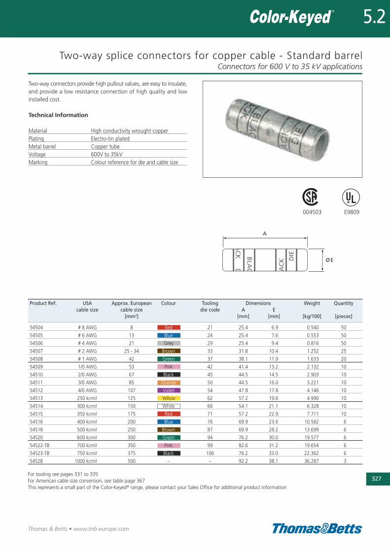
Two-way splice connectors for copper cable - Standard barrelConnectors for 600 V to 35 kV applications
327
Thomas & Betts • www.tnb-europe.com
5.2
Product Ref. USA Approx. European Colour Tooling Dimensions Weight Quantitycable size cable size die code A E
[mm2] [mm] [mm] [kg/100] [pieces]
54504 # 8 AWG 8 Red 21 25.4 6.9 0.540 50
54505 # 6 AWG 13 Blue 24 25.4 7.6 0.553 50
54506 # 4 AWG 21 Grey 29 25.4 9.4 0.816 50
54507 # 2 AWG 25 - 34 Brown 33 31.8 10.4 1.252 25
54508 # 1 AWG 42 Green 37 38.1 11.9 1.633 20
54509 1/0 AWG 53 Pink 42 41.4 13.2 2.132 10
54510 2/0 AWG 67 Black 45 44.5 14.5 2.903 10
54511 3/0 AWG 85 Orange 50 44.5 16.0 3.221 10
54512 4/0 AWG 107 Violet 54 47.8 17.8 4.146 10
54513 250 kcmil 125 Yellow 62 57.2 19.6 4.990 10
54514 300 kcmil 150 White 66 54.1 21.1 6.328 10
54515 350 kcmil 175 Red 71 57.2 22.9 7.711 10
54516 400 kcmil 200 Blue 76 69.9 23.6 10.582 6
54518 500 kcmil 250 Brown 87 69.9 28.2 13.699 6
54520 600 kcmil 300 Green 94 76.2 30.0 19.577 6
54522-TB 700 kcmil 350 Pink 99 82.6 31.2 19.654 6
54523-TB 750 kcmil 375 Black 106 76.2 33.0 22.362 6
54528 1000 kcmil 500 – – 92.2 38.1 36.287 3
For tooling see pages 331 to 335For American cable size conversion, see table page 367This represents a small part of the Color-Keyed® range, please contact your Sales Office for additional product information
Two-way connectors provide high pullout values, are easy to insulate,and provide a low resistance connection of high quality and lowinstalled cost.
Technical Information
Material High conductivity wrought copperPlating Electro-tin platedMetal barrel Copper tubeVoltage 600V to 35kVMarking Colour reference for die and cable size
004503 E9809
328
Thomas & Betts • www.tnb-europe.com
5.2
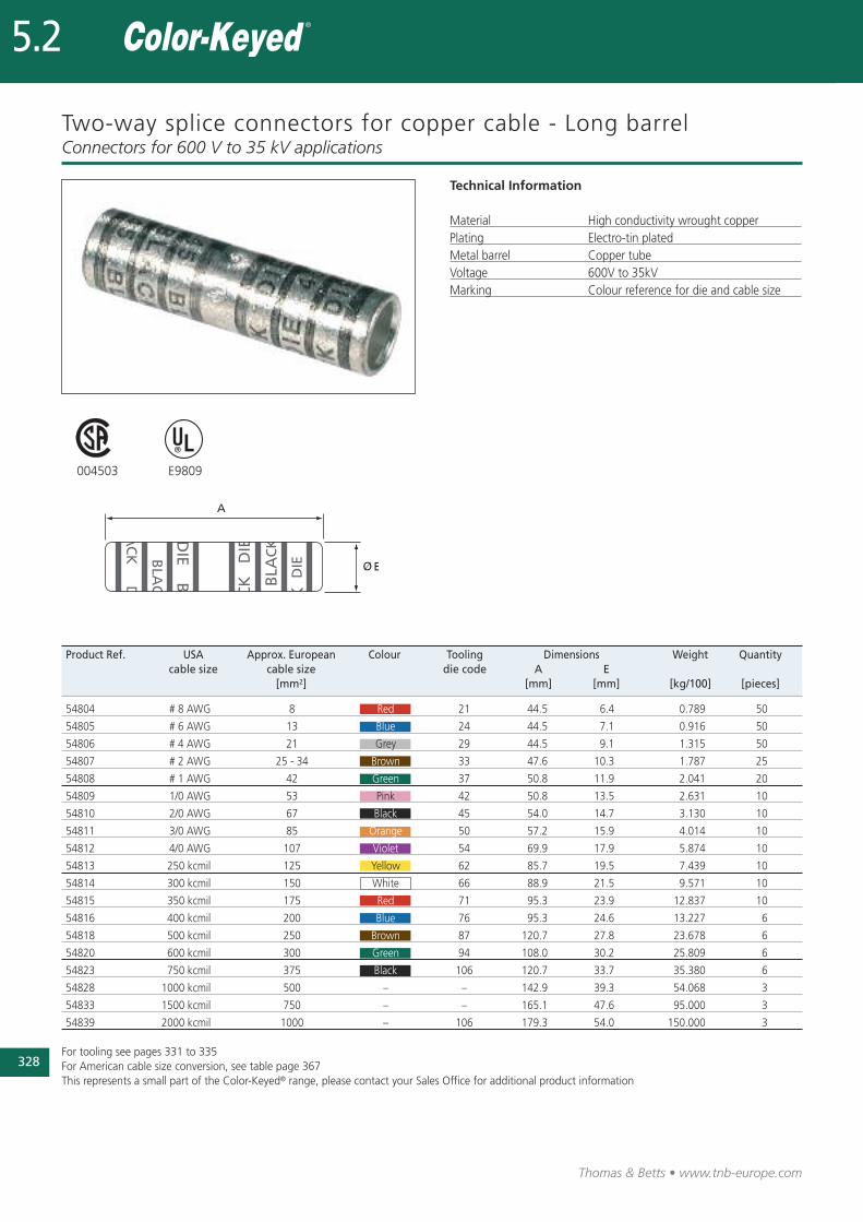
Two-way splice connectors for copper cable - Long barrel
Technical Information
Material High conductivity wrought copperPlating Electro-tin platedMetal barrel Copper tubeVoltage 600V to 35kVMarking Colour reference for die and cable size
Connectors for 600 V to 35 kV applications
004503 E9809
Product Ref. USA Approx. European Colour Tooling Dimensions Weight Quantitycable size cable size die code A E
[mm2] [mm] [mm] [kg/100] [pieces]
54804 # 8 AWG 8 Red 21 44.5 6.4 0.789 50
54805 # 6 AWG 13 Blue 24 44.5 7.1 0.916 50
54806 # 4 AWG 21 Grey 29 44.5 9.1 1.315 50
54807 # 2 AWG 25 - 34 Brown 33 47.6 10.3 1.787 25
54808 # 1 AWG 42 Green 37 50.8 11.9 2.041 20
54809 1/0 AWG 53 Pink 42 50.8 13.5 2.631 10
54810 2/0 AWG 67 Black 45 54.0 14.7 3.130 10
54811 3/0 AWG 85 Orange 50 57.2 15.9 4.014 10
54812 4/0 AWG 107 Violet 54 69.9 17.9 5.874 10
54813 250 kcmil 125 Yellow 62 85.7 19.5 7.439 10
54814 300 kcmil 150 White 66 88.9 21.5 9.571 10
54815 350 kcmil 175 Red 71 95.3 23.9 12.837 10
54816 400 kcmil 200 Blue 76 95.3 24.6 13.227 6
54818 500 kcmil 250 Brown 87 120.7 27.8 23.678 6
54820 600 kcmil 300 Green 94 108.0 30.2 25.809 6
54823 750 kcmil 375 Black 106 120.7 33.7 35.380 6
54828 1000 kcmil 500 – – 142.9 39.3 54.068 3
54833 1500 kcmil 750 – – 165.1 47.6 95.000 3
54839 2000 kcmil 1000 – 106 179.3 54.0 150.000 3
For tooling see pages 331 to 335For American cable size conversion, see table page 367This represents a small part of the Color-Keyed® range, please contact your Sales Office for additional product information
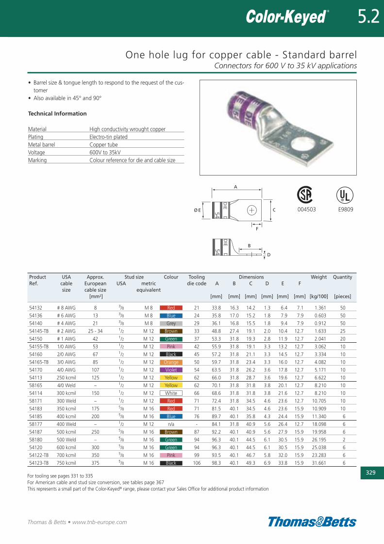
One hole lug for copper cable - Standard barrel
• Barrel size & tongue length to respond to the request of the cus-tomer
• Also available in 45° and 90°
Technical Information
Material High conductivity wrought copperPlating Electro-tin platedMetal barrel Copper tubeVoltage 600V to 35kVMarking Colour reference for die and cable size
Connectors for 600 V to 35 kV applications
329
Thomas & Betts • www.tnb-europe.com
5.2
004503 E9809
Product USA Approx. Stud size Colour Tooling Dimensions Weight QuantityRef. cable European USA metric die code A B C D E F
size cable size equivalent[mm2] [mm] [mm] [mm] [mm] [mm] [mm] [kg/100] [pieces]
54132 # 8 AWG 8 3/8 M 8 Red 21 33.8 16.3 14.2 1.3 6.4 7.1 1.361 50
54136 # 6 AWG 13 3/8 M 8 Blue 24 35.8 17.0 15.2 1.8 7.9 7.9 0.603 50
54140 # 4 AWG 21 3/8 M 8 Grey 29 36.1 16.8 15.5 1.8 9.4 7.9 0.912 50
54145-TB # 2 AWG 25 - 34 1/2 M 12 Brown 33 48.8 27.4 19.1 2.0 10.4 12.7 1.633 25
54150 # 1 AWG 42 1/2 M 12 Green 37 53.3 31.8 19.3 2.8 11.9 12.7 2.041 20
54155-TB 1/0 AWG 53 1/2 M 12 Pink 42 55.9 31.8 19.1 3.3 13.2 12.7 3.062 10
54160 2/0 AWG 67 1/2 M 12 Black 45 57.2 31.8 21.1 3.3 14.5 12.7 3.334 10
54165-TB 3/0 AWG 85 1/2 M 12 Orange 50 59.7 31.8 23.4 3.3 16.0 12.7 4.082 10
54170 4/0 AWG 107 1/2 M 12 Violet 54 63.5 31.8 26.2 3.6 17.8 12.7 5.171 10
54113 250 kcmil 125 1/2 M 12 Yellow 62 66.0 31.8 28.7 3.6 19.6 12.7 6.622 10
58165 4/0 Weld – 1/2 M 12 Yellow 62 70.1 31.8 31.8 3.8 20.1 12.7 8.210 10
54114 300 kcmil 150 1/2 M 12 White 66 68.6 31.8 31.8 3.8 21.6 12.7 8.210 10
58171 300 Weld – 1/2 M 12 Red 71 72.4 31.8 34.5 4.6 23.6 12.7 10.705 10
54183 350 kcmil 175 5/8 M 16 Red 71 81.5 40.1 34.5 4.6 23.6 15.9 10.909 10
54185 400 kcmil 200 5/8 M 16 Blue 76 89.7 40.1 35.8 4.3 24.4 15.9 11.340 6
58177 400 Weld – 1/2 M 12 n/a - 84.1 31.8 40.9 5.6 26.4 12.7 18.098 6
54187 500 kcmil 250 5/8 M 16 Brown 87 92.2 40.1 40.9 5.6 27.9 15.9 19.958 6
58180 500 Weld – 5/8 M 16 Green 94 96.3 40.1 44.5 6.1 30.5 15.9 26.195 2
54120 600 kcmil 300 5/8 M 16 Green 94 96.3 40.1 44.5 6.1 30.5 15.9 25.038 6
54122-TB 700 kcmil 350 5/8 M 16 Pink 99 93.5 40.1 46.7 5.8 32.0 15.9 23.283 6
54123-TB 750 kcmil 375 5/8 M 16 Black 106 98.3 40.1 49.3 6.9 33.8 15.9 31.661 6
For tooling see pages 331 to 335For American cable and stud size conversion, see tables page 367This represents a small part of the Color-Keyed® range, please contact your Sales Office for additional product information
330
Thomas & Betts • www.tnb-europe.com
5.2
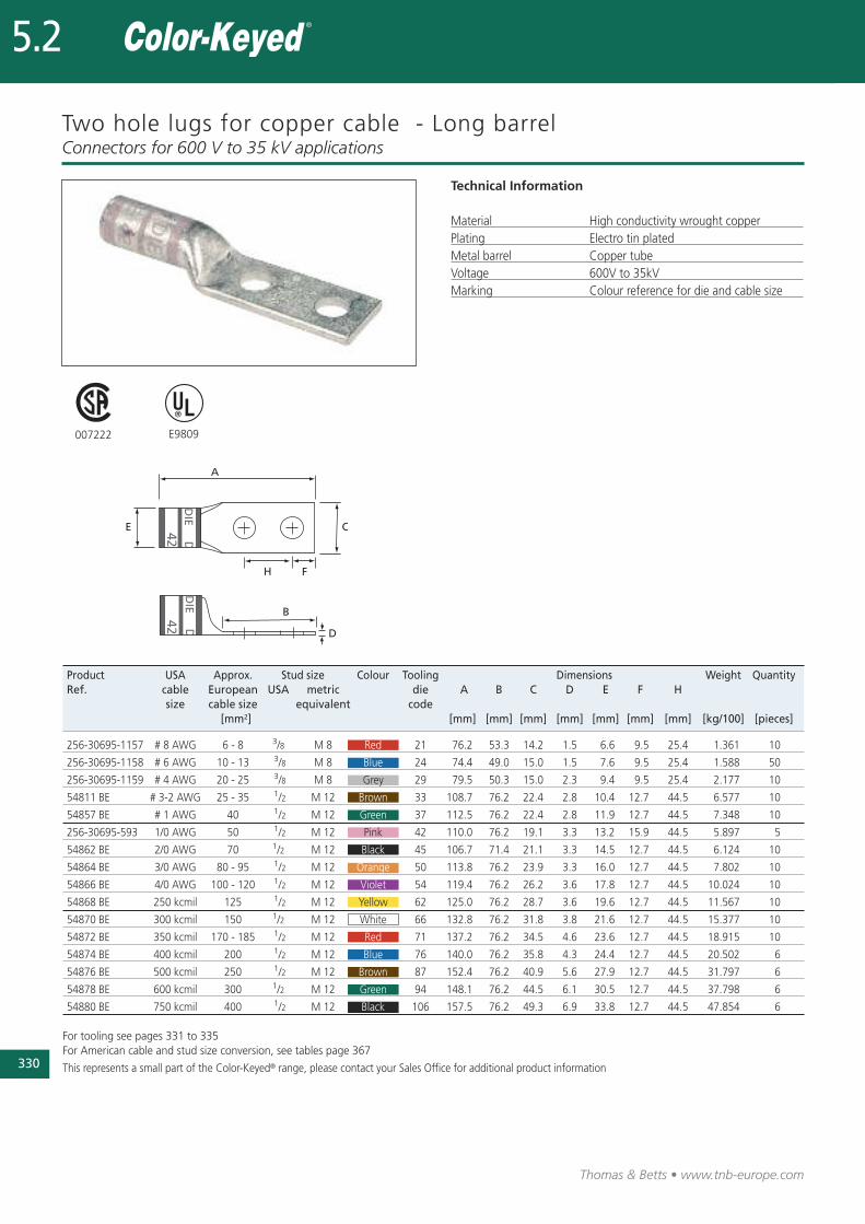
Two hole lugs for copper cable - Long barrel
Technical Information
Material High conductivity wrought copperPlating Electro tin platedMetal barrel Copper tubeVoltage 600V to 35kVMarking Colour reference for die and cable size
Connectors for 600 V to 35 kV applications
007222 E9809
Product USA Approx. Stud size Colour Tooling Dimensions Weight QuantityRef. cable European USA metric die A B C D E F H
size cable size equivalent code[mm2] [mm] [mm] [mm] [mm] [mm] [mm] [mm] [kg/100] [pieces]
256-30695-1157 # 8 AWG 6 - 8 3/8 M 8 Red 21 76.2 53.3 14.2 1.5 6.6 9.5 25.4 1.361 10
256-30695-1158 # 6 AWG 10 - 13 3/8 M 8 Blue 24 74.4 49.0 15.0 1.5 7.6 9.5 25.4 1.588 50
256-30695-1159 # 4 AWG 20 - 25 3/8 M 8 Grey 29 79.5 50.3 15.0 2.3 9.4 9.5 25.4 2.177 10
54811 BE # 3-2 AWG 25 - 35 1/2 M 12 Brown 33 108.7 76.2 22.4 2.8 10.4 12.7 44.5 6.577 10
54857 BE # 1 AWG 40 1/2 M 12 Green 37 112.5 76.2 22.4 2.8 11.9 12.7 44.5 7.348 10
256-30695-593 1/0 AWG 50 1/2 M 12 Pink 42 110.0 76.2 19.1 3.3 13.2 15.9 44.5 5.897 5
54862 BE 2/0 AWG 70 1/2 M 12 Black 45 106.7 71.4 21.1 3.3 14.5 12.7 44.5 6.124 10
54864 BE 3/0 AWG 80 - 95 1/2 M 12 Orange 50 113.8 76.2 23.9 3.3 16.0 12.7 44.5 7.802 10
54866 BE 4/0 AWG 100 - 120 1/2 M 12 Violet 54 119.4 76.2 26.2 3.6 17.8 12.7 44.5 10.024 10
54868 BE 250 kcmil 125 1/2 M 12 Yellow 62 125.0 76.2 28.7 3.6 19.6 12.7 44.5 11.567 10
54870 BE 300 kcmil 150 1/2 M 12 White 66 132.8 76.2 31.8 3.8 21.6 12.7 44.5 15.377 10
54872 BE 350 kcmil 170 - 185 1/2 M 12 Red 71 137.2 76.2 34.5 4.6 23.6 12.7 44.5 18.915 10
54874 BE 400 kcmil 200 1/2 M 12 Blue 76 140.0 76.2 35.8 4.3 24.4 12.7 44.5 20.502 6
54876 BE 500 kcmil 250 1/2 M 12 Brown 87 152.4 76.2 40.9 5.6 27.9 12.7 44.5 31.797 6
54878 BE 600 kcmil 300 1/2 M 12 Green 94 148.1 76.2 44.5 6.1 30.5 12.7 44.5 37.798 6
54880 BE 750 kcmil 400 1/2 M 12 Black 106 157.5 76.2 49.3 6.9 33.8 12.7 44.5 47.854 6
For tooling see pages 331 to 335For American cable and stud size conversion, see tables page 367
This represents a small part of the Color-Keyed® range, please contact your Sales Office for additional product information
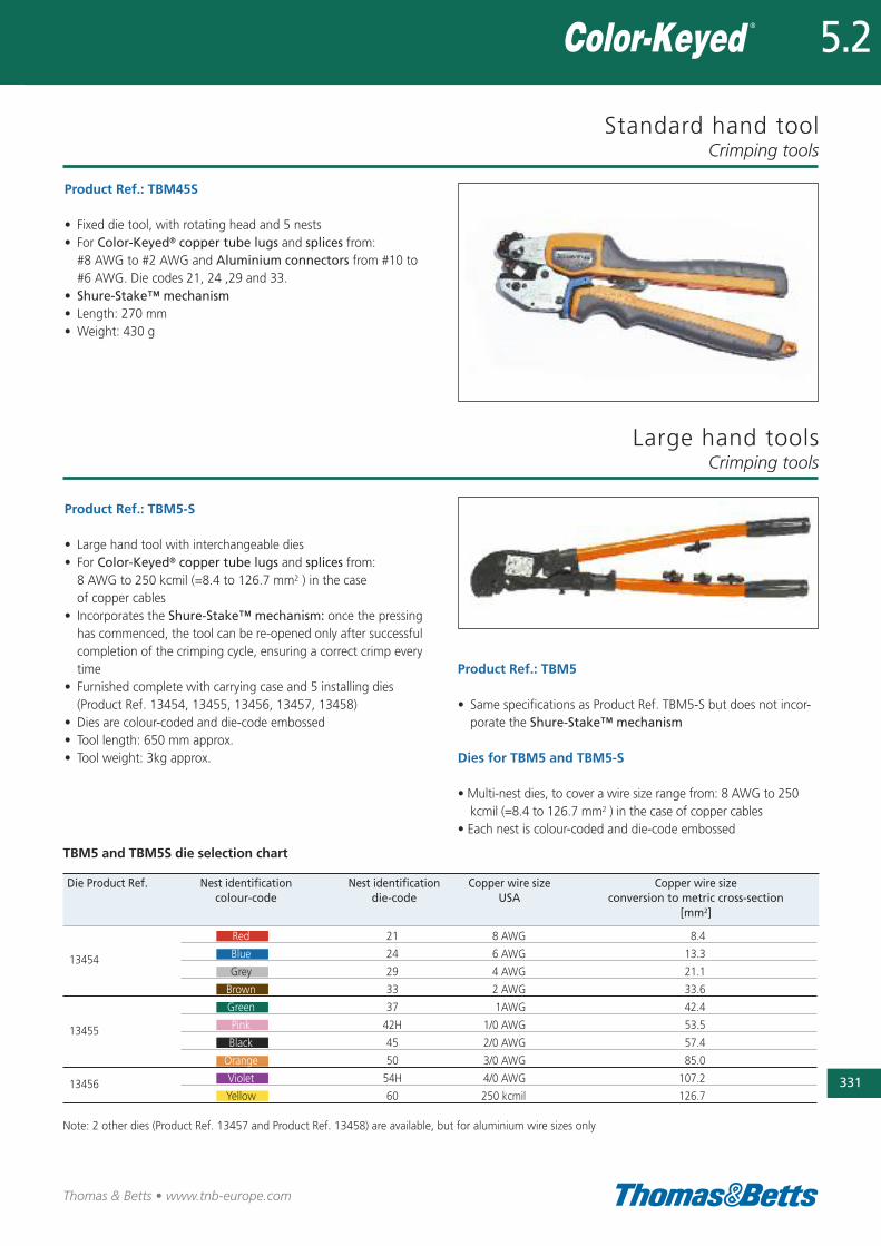
Standard hand tool
Product Ref.: TBM45S
• Fixed die tool, with rotating head and 5 nests • For Color-Keyed® copper tube lugs and splices from:#8 AWG to #2 AWG and Aluminium connectors from #10 to#6 AWG. Die codes 21, 24 ,29 and 33.
• Shure-Stake™ mechanism• Length: 270 mm• Weight: 430 g
Crimping tools
331
Thomas & Betts • www.tnb-europe.com
5.2
Product Ref.: TBM5-S
• Large hand tool with interchangeable dies• For Color-Keyed® copper tube lugs and splices from: 8 AWG to 250 kcmil (=8.4 to 126.7 mm2 ) in the case of copper cables
• Incorporates the Shure-Stake™ mechanism: once the pressinghas commenced, the tool can be re-opened only after successfulcompletion of the crimping cycle, ensuring a correct crimp everytime
• Furnished complete with carrying case and 5 installing dies (Product Ref. 13454, 13455, 13456, 13457, 13458)
• Dies are colour-coded and die-code embossed• Tool length: 650 mm approx.• Tool weight: 3kg approx.
Die Product Ref. Nest identification Nest identification Copper wire size Copper wire sizecolour-code die-code USA conversion to metric cross-section
[mm2]
Red 21 8 AWG 8.4
Blue 24 6 AWG 13.313454Grey 29 4 AWG 21.1
Brown 33 2 AWG 33.6
Green 37 1AWG 42.4
Pink 42H 1/0 AWG 53.513455Black 45 2/0 AWG 57.4
Orange 50 3/0 AWG 85.0
Violet 54H 4/0 AWG 107.213456Yellow 60 250 kcmil 126.7
Note: 2 other dies (Product Ref. 13457 and Product Ref. 13458) are available, but for aluminium wire sizes only
Large hand toolsCrimping tools
Product Ref.: TBM5
• Same specifications as Product Ref. TBM5-S but does not incor-porate the Shure-Stake™ mechanism
Dies for TBM5 and TBM5-S
• Multi-nest dies, to cover a wire size range from: 8 AWG to 250kcmil (=8.4 to 126.7 mm2 ) in the case of copper cables
• Each nest is colour-coded and die-code embossed
TBM5 and TBM5S die selection chart
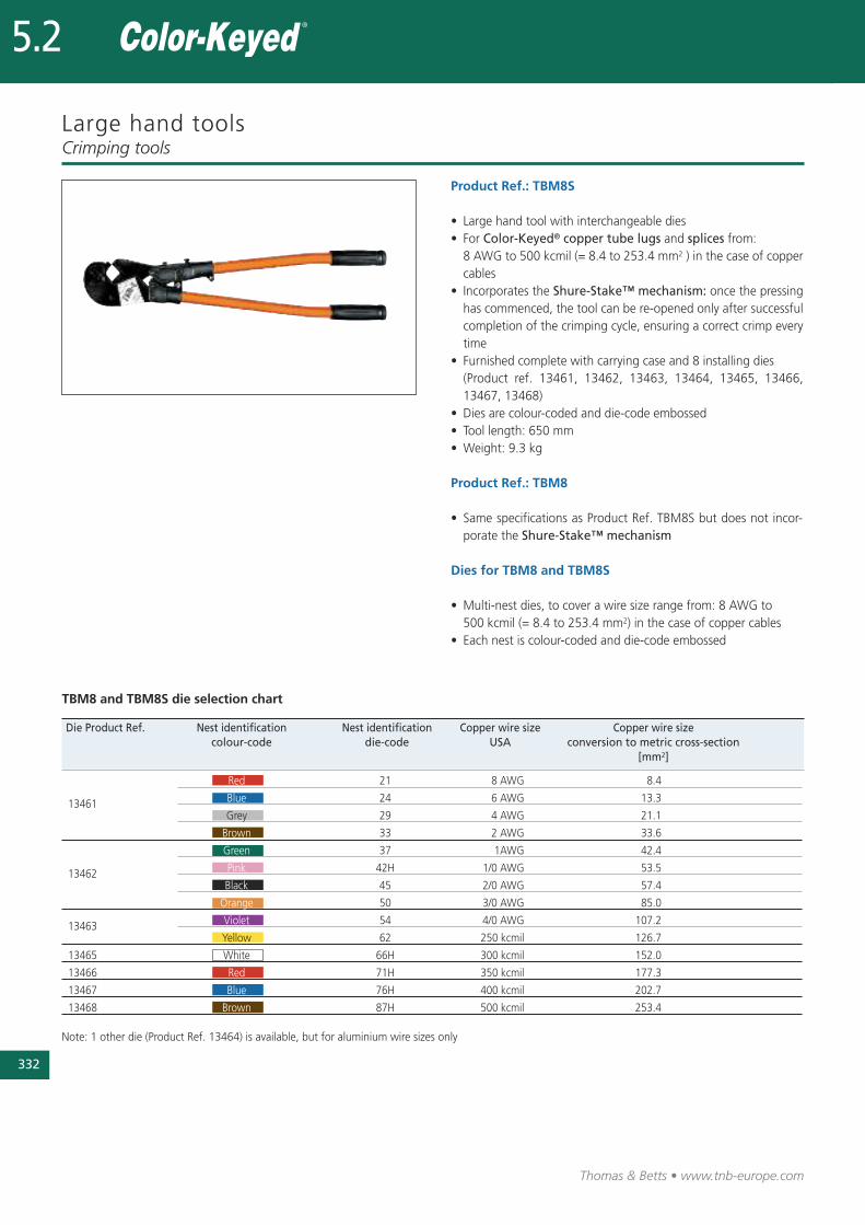
Thomas & Betts • www.tnb-europe.com
Large hand tools
Product Ref.: TBM8S
• Large hand tool with interchangeable dies• For Color-Keyed® copper tube lugs and splices from: 8 AWG to 500 kcmil (= 8.4 to 253.4 mm2 ) in the case of coppercables
• Incorporates the Shure-Stake™ mechanism: once the pressinghas commenced, the tool can be re-opened only after successfulcompletion of the crimping cycle, ensuring a correct crimp everytime
• Furnished complete with carrying case and 8 installing dies (Product ref. 13461, 13462, 13463, 13464, 13465, 13466,13467, 13468)
• Dies are colour-coded and die-code embossed• Tool length: 650 mm• Weight: 9.3 kg
Product Ref.: TBM8
• Same specifications as Product Ref. TBM8S but does not incor-porate the Shure-Stake™ mechanism
Dies for TBM8 and TBM8S
• Multi-nest dies, to cover a wire size range from: 8 AWG to 500 kcmil (= 8.4 to 253.4 mm2) in the case of copper cables
• Each nest is colour-coded and die-code embossed
Crimping tools
Die Product Ref. Nest identification Nest identification Copper wire size Copper wire sizecolour-code die-code USA conversion to metric cross-section
[mm2]
Red 21 8 AWG 8.4
Blue 24 6 AWG 13.313461Grey 29 4 AWG 21.1
Brown 33 2 AWG 33.6
Green 37 1AWG 42.4
Pink 42H 1/0 AWG 53.513462Black 45 2/0 AWG 57.4
Orange 50 3/0 AWG 85.0
Violet 54 4/0 AWG 107.213463Yellow 62 250 kcmil 126.7
13465 White 66H 300 kcmil 152.0
13466 Red 71H 350 kcmil 177.3
13467 Blue 76H 400 kcmil 202.7
13468 Brown 87H 500 kcmil 253.4
Note: 1 other die (Product Ref. 13464) is available, but for aluminium wire sizes only
332
5.2
TBM8 and TBM8S die selection chart
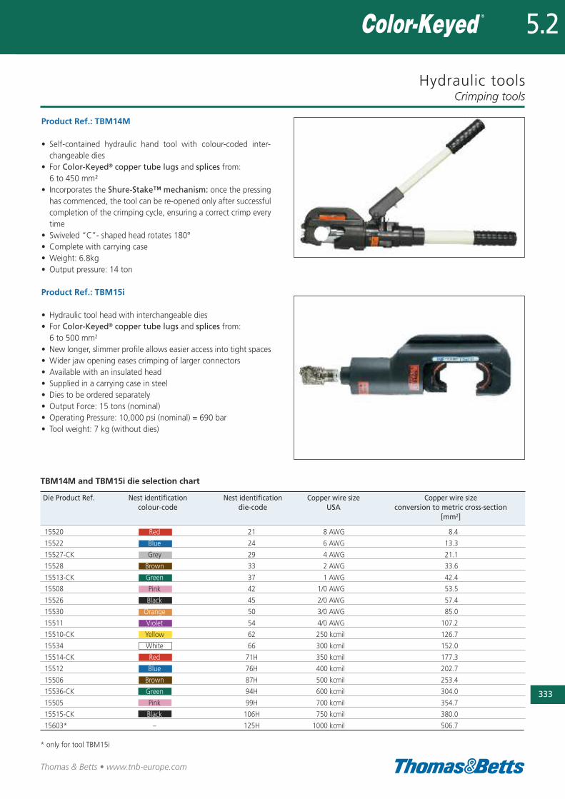
Hydraulic tools
Product Ref.: TBM14M
• Self-contained hydraulic hand tool with colour-coded inter-changeable dies
• For Color-Keyed® copper tube lugs and splices from:6 to 450 mm²
• Incorporates the Shure-Stake™ mechanism: once the pressinghas commenced, the tool can be re-opened only after successfulcompletion of the crimping cycle, ensuring a correct crimp everytime
• Swiveled “C”- shaped head rotates 180°• Complete with carrying case• Weight: 6.8kg• Output pressure: 14 ton
Product Ref.: TBM15i
• Hydraulic tool head with interchangeable dies • For Color-Keyed® copper tube lugs and splices from: 6 to 500 mm2
• New longer, slimmer profile allows easier access into tight spaces• Wider jaw opening eases crimping of larger connectors• Available with an insulated head • Supplied in a carrying case in steel• Dies to be ordered separately• Output Force: 15 tons (nominal)• Operating Pressure: 10,000 psi (nominal) = 690 bar• Tool weight: 7 kg (without dies)
Crimping tools
333
Thomas & Betts • www.tnb-europe.com
5.2
Die Product Ref. Nest identification Nest identification Copper wire size Copper wire sizecolour-code die-code USA conversion to metric cross-section
[mm2]
15520 Red 21 8 AWG 8.4
15522 Blue 24 6 AWG 13.3
15527-CK Grey 29 4 AWG 21.1
15528 Brown 33 2 AWG 33.6
15513-CK Green 37 1 AWG 42.4
15508 Pink 42 1/0 AWG 53.5
15526 Black 45 2/0 AWG 57.4
15530 Orange 50 3/0 AWG 85.0
15511 Violet 54 4/0 AWG 107.2
15510-CK Yellow 62 250 kcmil 126.7
15534 White 66 300 kcmil 152.0
15514-CK Red 71H 350 kcmil 177.3
15512 Blue 76H 400 kcmil 202.7
15506 Brown 87H 500 kcmil 253.4
15536-CK Green 94H 600 kcmil 304.0
15505 Pink 99H 700 kcmil 354.7
15515-CK Black 106H 750 kcmil 380.0
15603* – 125H 1000 kcmil 506.7
* only for tool TBM15i
TBM14M and TBM15i die selection chart
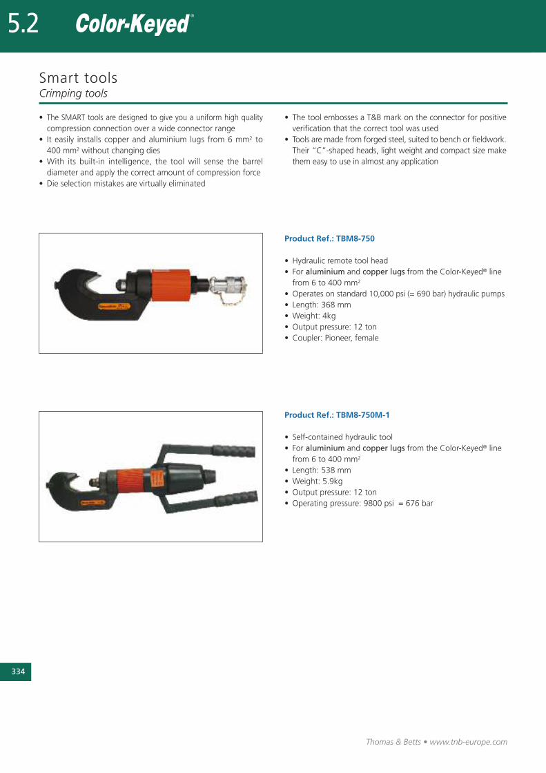
334
Thomas & Betts • www.tnb-europe.com
5.2
Smart tools
Product Ref.: TBM8-750
• Hydraulic remote tool head • For aluminium and copper lugs from the Color-Keyed® linefrom 6 to 400 mm2
• Operates on standard 10,000 psi (= 690 bar) hydraulic pumps• Length: 368 mm• Weight: 4kg• Output pressure: 12 ton• Coupler: Pioneer, female
Product Ref.: TBM8-750M-1
• Self-contained hydraulic tool• For aluminium and copper lugs from the Color-Keyed® linefrom 6 to 400 mm2
• Length: 538 mm• Weight: 5.9kg• Output pressure: 12 ton• Operating pressure: 9800 psi = 676 bar
Crimping tools
• The SMART tools are designed to give you a uniform high qualitycompression connection over a wide connector range
• It easily installs copper and aluminium lugs from 6 mm2 to400 mm2 without changing dies
• With its built-in intelligence, the tool will sense the barreldiameter and apply the correct amount of compression force
• Die selection mistakes are virtually eliminated
• The tool embosses a T&B mark on the connector for positiveverification that the correct tool was used
• Tools are made from forged steel, suited to bench or fieldwork.Their “C”-shaped heads, light weight and compact size makethem easy to use in almost any application
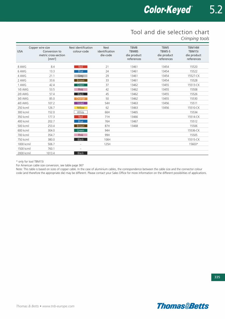
Tool and die selection chartCrimping tools
335
Thomas & Betts • www.tnb-europe.com
5.2
Copper wire size Nest identification Nest TBM8 TBM5 TBM14MUSA Conversion to colour-code identification TBM8S TBM5-S TBM15i
metric cross-section die-code die product die product die product[mm2] references references references
8 AWG 8.4 Red 21 13461 13454 15520
6 AWG 13.3 Blue 24 13461 13454 15522
4 AWG 21.1 Grey 29 13461 13454 15527-CK
2 AWG 33.6 Brown 33 13461 13454 15528
1 AWG 42.4 Green 37 13462 13455 15513-CK
1/0 AWG 53.5 Pink 42 13462 13455 15508
2/0 AWG 57.4 Black 45 13462 13455 15526
3/0 AWG 85.0 Orange 50 13462 13455 15530
4/0 AWG 107.2 Violet 54H 13463 13456 15511
250 kcmil 126.7 Yellow 62 13463 13456 15510-CK
300 kcmil 152.0 White 66H 13465 15534
350 kcmil 177.3 Red 71H 13466 15514-CK
400 kcmil 202.7 Blue 76H 13467 15512
500 kcmil 253.4 Brown 87H 13468 15506
600 kcmil 304.0 Green 94H 15536-CK
700 kcmil 354.7 Pink 99H 15505
750 kcmil 380.0 Black 106H 15515-CK
1000 kcmil 506.7 – 125H 15603*
1500 kcmil 760.1 –
2000 kcmil 1013.4 Black
* only for tool TBM15iFor American cable size conversion, see table page 367Note: This table is based on sizes of copper cable. In the case of aluminium cables, the correspondence between the cable size and the connector colourcode (and therefore the appropriate die) may be different. Please contact your Sales Office for more information on the different possibilities of applications.

336
Thomas & Betts • www.tnb-europe.com
Dragon Tooth ®
Insulat ion pierc ingconnectors to spl ice,
tap and terminatemagnet wire
5.3
337
Thomas & Betts • www.tnb-europe.com
5.3
TERMINATION SYSTEMS
5.1 STA-KON® - CRIMP TERMINALS 278
5.2 COLOR-KEYED® - POWER CABLE CONNECTORS 322
5.3 DRAGON TOOTH® - MAGNET WIRE TERMINALS 336
Insulation piercing connectors 340
Overview 340
Splices 341
Ring terminals 348
Fork terminals 353
Disconnect terminals 354
Taps 356
Modular connectors 357
Washers 359
Crimping tools 360
Hand tools 360
Air-operated tools 361
Auto-feed tools for connectors on strip 362
Hydraulic tools 363
Connectors, tool and die selection chart 365
5.4 SHIELD-KON® - SHIELDED CABLE CONNECTORS 368

Thomas & Betts • www.tnb-europe.com
5.3
Dragon Tooth ®
The insulat ion pierc ing connector
The Dragon Tooth® insulation piercing connectors for
magnet wire penetrate the insulation and oxide layers to
make a reliable electrical contact, eliminating the need for
stripping, brazing, welding or other methods of joining
magnet wire.
In the conventional methods, different techniques are used to
remove the insulating varnish: scratching, brushing, burning-off,
dissolving. These methods are all costly and time consuming, and
they generally lead to a risk of damage to the conductors and to
a risk of injury of the operator. Health and environmental conside-
rations can also be an issue. 338
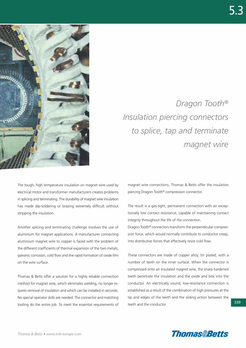
339
Thomas & Betts • www.tnb-europe.com
5.3
Dragon Tooth®
Insulation piercing connectors
to splice, tap and terminate
magnet wire
The tough, high temperature insulation on magnet wire used by
electrical motor and transformer manufacturers creates problems
in splicing and terminating. The durability of magnet wire insulation
has made dip-soldering or brazing extremely difficult without
stripping the insulation.
Another splicing and terminating challenge involves the use of
aluminium for magnet applications. A manufacturer connecting
aluminium magnet wire to copper is faced with the problem of
the different coefficients of thermal expansion of the two metals,
galvanic corrosion, cold flow and the rapid formation of oxide film
on the wire surface.
Thomas & Betts offer a solution for a highly reliable connection
method for magnet wire, which eliminates welding, no longer re-
quires removal of insulation and which can be installed in seconds.
No special operator skills are needed. The connector and matching
tooling do the entire job. To meet the essential requirements of
magnet wire connections, Thomas & Betts offer the insulation
piercing Dragon Tooth® compression connector.
The result is a gas-tight, permanent connection with an excep-
tionally low contact resistance, capable of maintaining contact
integrity throughout the life of the connection.
Dragon Tooth® connectors transform the perpendicular compres-
sion force, which would normally contribute to conductor creep,
into distributive forces that effectively resist cold flow.
These connectors are made of copper alloy, tin plated, with a
number of teeth on the inner surface. When the connector is
compressed onto an insulated magnet wire, the sharp hardened
teeth penetrate the insulation and the oxide and bite into the
conductor. An electrically sound, low-resistance connection is
established as a result of the combination of high pressures at the
tip and edges of the teeth and the sliding action between the
teeth and the conductor
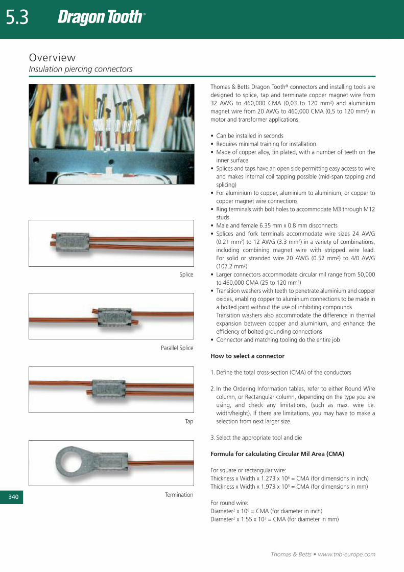
340
Thomas & Betts • www.tnb-europe.com
5.3
Overview
Thomas & Betts Dragon Tooth® connectors and installing tools aredesigned to splice, tap and terminate copper magnet wire from32 AWG to 460,000 CMA (0,03 to 120 mm2) and aluminiummagnet wire from 20 AWG to 460,000 CMA (0,5 to 120 mm2) inmotor and transformer applications.
• Can be installed in seconds• Requires minimal training for installation.• Made of copper alloy, tin plated, with a number of teeth on theinner surface
• Splices and taps have an open side permitting easy access to wireand makes internal coil tapping possible (mid-span tapping andsplicing)
• For aluminium to copper, aluminium to aluminium, or copper tocopper magnet wire connections
• Ring terminals with bolt holes to accommodate M3 through M12studs
• Male and female 6.35 mm x 0.8 mm disconnects• Splices and fork terminals accommodate wire sizes 24 AWG(0.21 mm2) to 12 AWG (3.3 mm2) in a variety of combinations,including combining magnet wire with stripped wire lead.For solid or stranded wire 20 AWG (0.52 mm2) to 4/0 AWG(107.2 mm2)
• Larger connectors accommodate circular mil range from 50,000to 460,000 CMA (25 to 120 mm2)
• Transition washers with teeth to penetrate aluminium and copperoxides, enabling copper to aluminium connections to be made ina bolted joint without the use of inhibiting compoundsTransition washers also accommodate the difference in thermalexpansion between copper and aluminium, and enhance theefficiency of bolted grounding connections
• Connector and matching tooling do the entire job
How to select a connector
1.Define the total cross-section (CMA) of the conductors
2. In the Ordering Information tables, refer to either Round Wirecolumn, or Rectangular column, depending on the type you areusing, and check any limitations, (such as max. wire i.e.width/height). If there are limitations, you may have to make aselection from next larger size.
3. Select the appropriate tool and die
Formula for calculating Circular Mil Area (CMA)
For square or rectangular wire:Thickness x Width x 1.273 x 106 = CMA (for dimensions in inch)Thickness x Width x 1.973 x 103 = CMA (for dimensions in mm)
For round wire:Diameter2 x 106 = CMA (for diameter in inch)Diameter2 x 1.55 x 103 = CMA (for diameter in mm)
Insulation piercing connectors
Splice
Parallel Splice
Tap
Termination
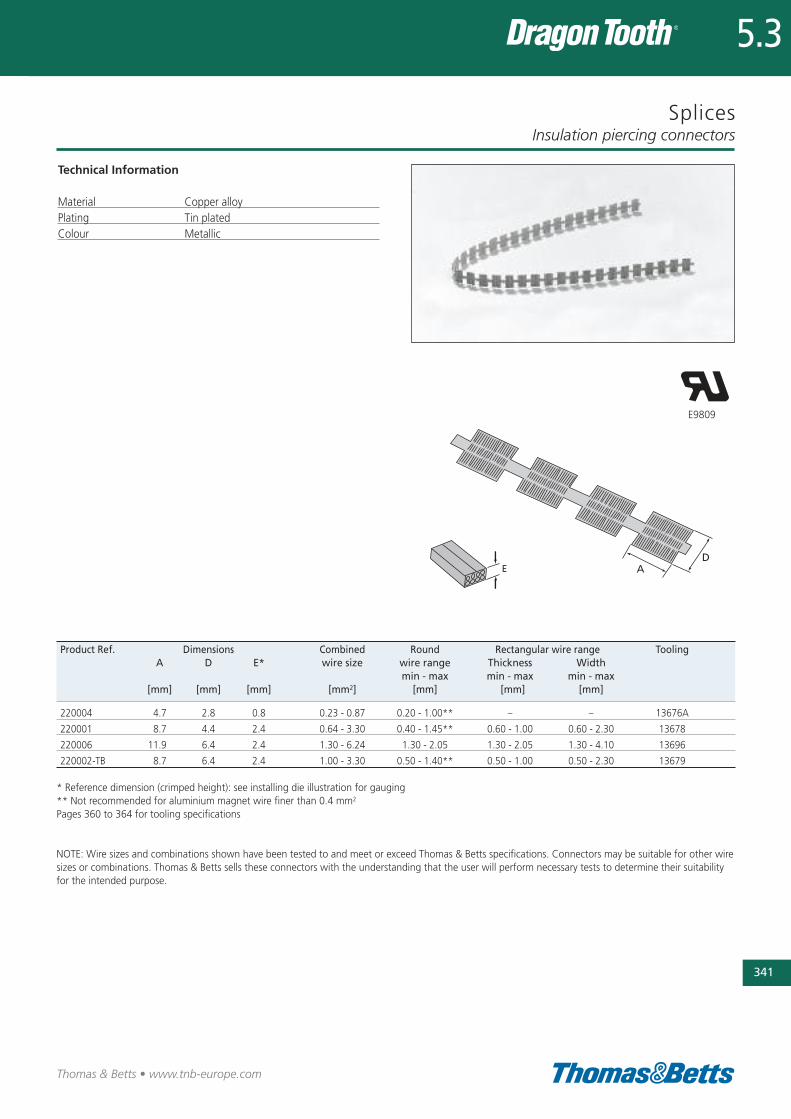
Splices
Technical Information
Material Copper alloyPlating Tin platedColour Metallic
Insulation piercing connectors
341
Thomas & Betts • www.tnb-europe.com
5.3
Product Ref. Dimensions Combined Round Rectangular wire range ToolingA D E* wire size wire range Thickness Width
min - max min - max min - max[mm] [mm] [mm] [mm2] [mm] [mm] [mm]
220004 4.7 2.8 0.8 0.23 - 0.87 0.20 - 1.00** – – 13676A
220001 8.7 4.4 2.4 0.64 - 3.30 0.40 - 1.45** 0.60 - 1.00 0.60 - 2.30 13678
220006 11.9 6.4 2.4 1.30 - 6.24 1.30 - 2.05 1.30 - 2.05 1.30 - 4.10 13696
220002-TB 8.7 6.4 2.4 1.00 - 3.30 0.50 - 1.40** 0.50 - 1.00 0.50 - 2.30 13679
* Reference dimension (crimped height): see installing die illustration for gauging** Not recommended for aluminium magnet wire finer than 0.4 mm2
Pages 360 to 364 for tooling specifications
NOTE: Wire sizes and combinations shown have been tested to and meet or exceed Thomas & Betts specifications. Connectors may be suitable for other wiresizes or combinations. Thomas & Betts sells these connectors with the understanding that the user will perform necessary tests to determine their suitabilityfor the intended purpose.
E9809
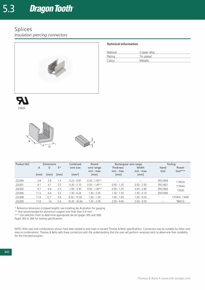
342
Thomas & Betts • www.tnb-europe.com
5.3
Splices
Technical Information
Material Copper alloyPlating Tin platedColour Metallic
Insulation piercing connectors
Product Ref. Dimensions Combined Round Rectangular wire range ToolingA D E* wire size wire range Thickness Width Hand Power
min - max min - max min - max tool tool***[mm] [mm] [mm] [mm2] [mm] [mm] [mm]
22L004 3.8 2.8 1.3 0.23 - 0.87 0.20 - 1.00** – – ERG1804
22L001 8.1 4.1 2.5 0.20 - 2.10 0.50 - 1.45** 0.50 - 1.25 0.50 - 2.50 ERG180111903A
22L002 8.1 6.4 2.5 1.00 - 3.30 0.50 - 1.40** 0.50 - 1.25 0.50 - 2.80 ERG180211904A
22L006 11.5 6.4 3.3 1.30 - 6.24 1.30 - 2.05 1.30 - 1.50 1.30 - 4.10 ERG180613500
22L008 17.8 12.7 3.8 6.50 - 15.50 1.00 - 1.30 1.00 - 1.60 1.60 - 9.53 – 13100A, 13400
22L009 17.8 14 5.6 18.30 - 43.60 1.30 - 2.58 2.00 - 4.60 2.00 - 9.50 – TBM15i
* Reference dimension (crimped height): see installing die illustration for gauging** Not recommended for aluminium magnet wire finer than 0.4 mm2
*** Use selection chart to determine appropriate die set (pages 365 and 366)Pages 360 to 364 for tooling specifications
NOTE: Wire sizes and combinations shown have been tested to and meet or exceed Thomas & Betts specifications. Connectors may be suitable for other wiresizes or combinations. Thomas & Betts sells these connectors with the understanding that the user will perform necessary tests to determine their suitabilityfor the intended purpose.
E9809
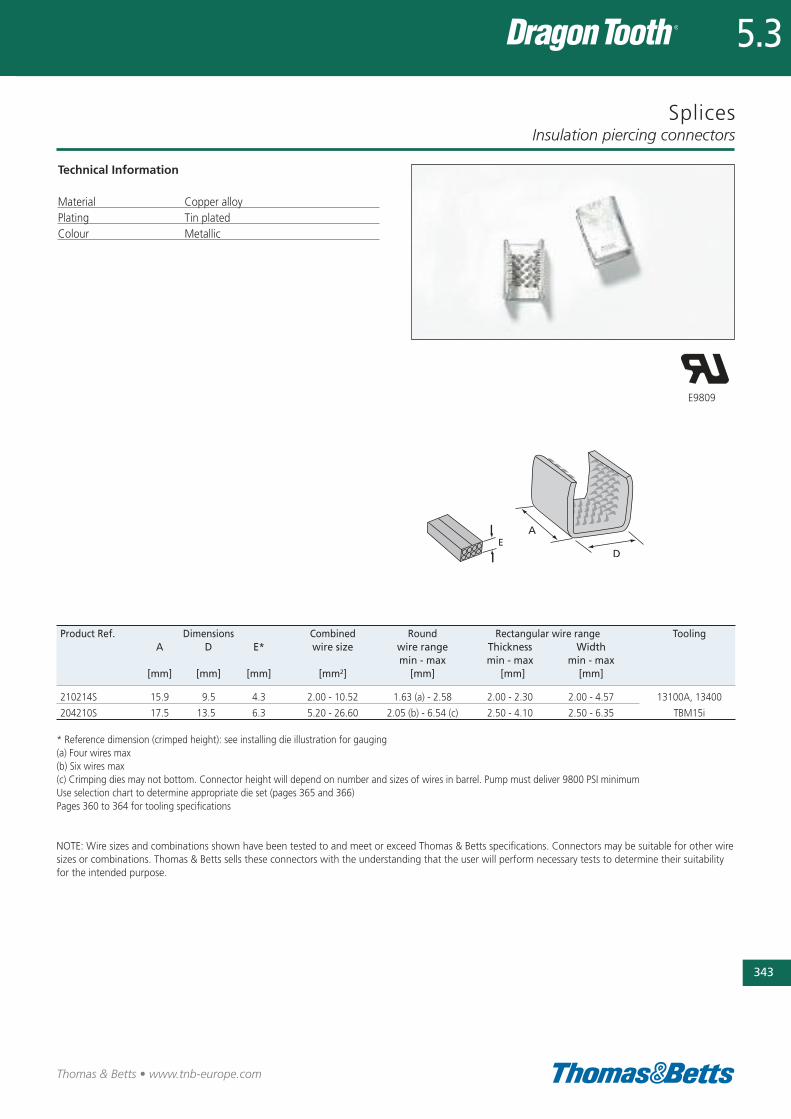
Splices
Technical Information
Material Copper alloyPlating Tin platedColour Metallic
Insulation piercing connectors
343
Thomas & Betts • www.tnb-europe.com
5.3
E9809
Product Ref. Dimensions Combined Round Rectangular wire range ToolingA D E* wire size wire range Thickness Width
min - max min - max min - max[mm] [mm] [mm] [mm2] [mm] [mm] [mm]
210214S 15.9 9.5 4.3 2.00 - 10.52 1.63 (a) - 2.58 2.00 - 2.30 2.00 - 4.57 13100A, 13400
204210S 17.5 13.5 6.3 5.20 - 26.60 2.05 (b) - 6.54 (c) 2.50 - 4.10 2.50 - 6.35 TBM15i
* Reference dimension (crimped height): see installing die illustration for gauging(a) Four wires max(b) Six wires max(c) Crimping dies may not bottom. Connector height will depend on number and sizes of wires in barrel. Pump must deliver 9800 PSI minimumUse selection chart to determine appropriate die set (pages 365 and 366)Pages 360 to 364 for tooling specifications
NOTE: Wire sizes and combinations shown have been tested to and meet or exceed Thomas & Betts specifications. Connectors may be suitable for other wiresizes or combinations. Thomas & Betts sells these connectors with the understanding that the user will perform necessary tests to determine their suitabilityfor the intended purpose.
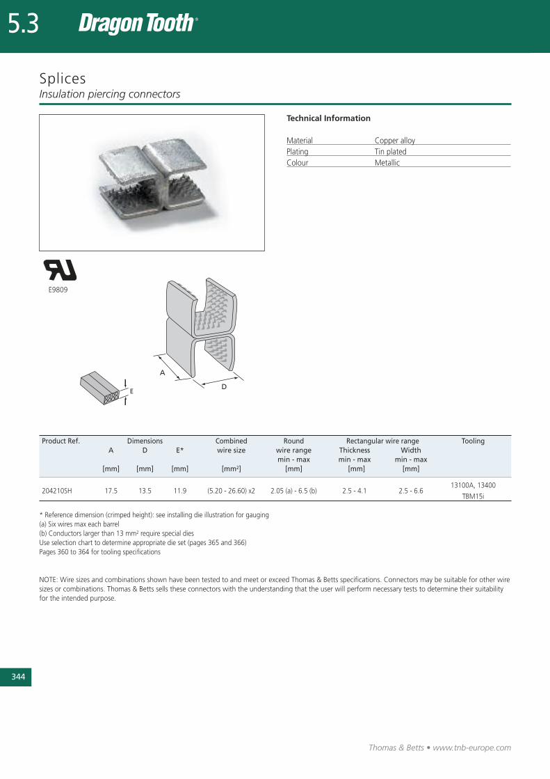
344
Thomas & Betts • www.tnb-europe.com
5.3
Splices
Technical Information
Material Copper alloyPlating Tin platedColour Metallic
Insulation piercing connectors
Product Ref. Dimensions Combined Round Rectangular wire range ToolingA D E* wire size wire range Thickness Width
min - max min - max min - max[mm] [mm] [mm] [mm2] [mm] [mm] [mm]
204210SH 17.5 13.5 11.9 (5.20 - 26.60) x2 2.05 (a) - 6.5 (b) 2.5 - 4.1 2.5 - 6.613100A, 13400
TBM15i
* Reference dimension (crimped height): see installing die illustration for gauging(a) Six wires max each barrel(b) Conductors larger than 13 mm2 require special diesUse selection chart to determine appropriate die set (pages 365 and 366)Pages 360 to 364 for tooling specifications
NOTE: Wire sizes and combinations shown have been tested to and meet or exceed Thomas & Betts specifications. Connectors may be suitable for other wiresizes or combinations. Thomas & Betts sells these connectors with the understanding that the user will perform necessary tests to determine their suitabilityfor the intended purpose.
E9809
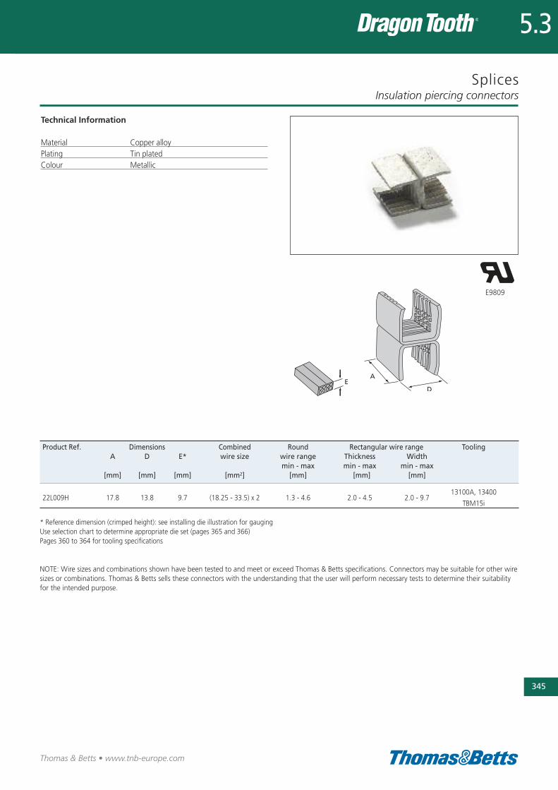
Splices
Technical Information
Material Copper alloyPlating Tin platedColour Metallic
Insulation piercing connectors
345
Thomas & Betts • www.tnb-europe.com
5.3
Product Ref. Dimensions Combined Round Rectangular wire range ToolingA D E* wire size wire range Thickness Width
min - max min - max min - max[mm] [mm] [mm] [mm2] [mm] [mm] [mm]
22L009H 17.8 13.8 9.7 (18.25 - 33.5) x 2 1.3 - 4.6 2.0 - 4.5 2.0 - 9.713100A, 13400
TBM15i
* Reference dimension (crimped height): see installing die illustration for gaugingUse selection chart to determine appropriate die set (pages 365 and 366)Pages 360 to 364 for tooling specifications
NOTE: Wire sizes and combinations shown have been tested to and meet or exceed Thomas & Betts specifications. Connectors may be suitable for other wiresizes or combinations. Thomas & Betts sells these connectors with the understanding that the user will perform necessary tests to determine their suitabilityfor the intended purpose.
E9809
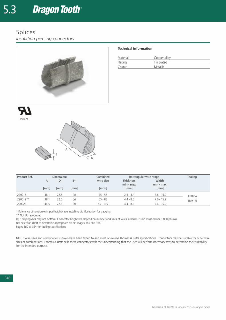
Thomas & Betts • www.tnb-europe.com
Splices
Technical Information
Material Copper alloyPlating Tin platedColour Metallic
Insulation piercing connectors
Product Ref. Dimensions Combined Rectangular wire range ToolingA D E* wire size Thickness Width
min - max min - max [mm] [mm] [mm] [mm2] [mm] [mm]
220015 38.1 22.5 (a) 25 - 58 2.5 - 4.4 7.6 - 15.9 13100A220019** 38.1 22.5 (a) 55 - 88 4.4 - 8.3 7.6 - 15.9 TBM15i220023 44.5 22.5 (a) 55 - 115 4.4 - 8.3 7.6 - 15.9
* Reference dimension (crimped height): see installing die illustration for gauging** Not UL recognised(a) Crimping dies may not bottom. Connector height will depend on number and sizes of wires in barrel. Pump must deliver 9.800 psi min.Use selection chart to determine appropriate die set (pages 365 and 366)Pages 360 to 364 for tooling specifications
NOTE: Wire sizes and combinations shown have been tested to and meet or exceed Thomas & Betts specifications. Connectors may be suitable for other wiresizes or combinations. Thomas & Betts sells these connectors with the understanding that the user will perform necessary tests to determine their suitabilityfor the intended purpose.
E9809
5.3
346
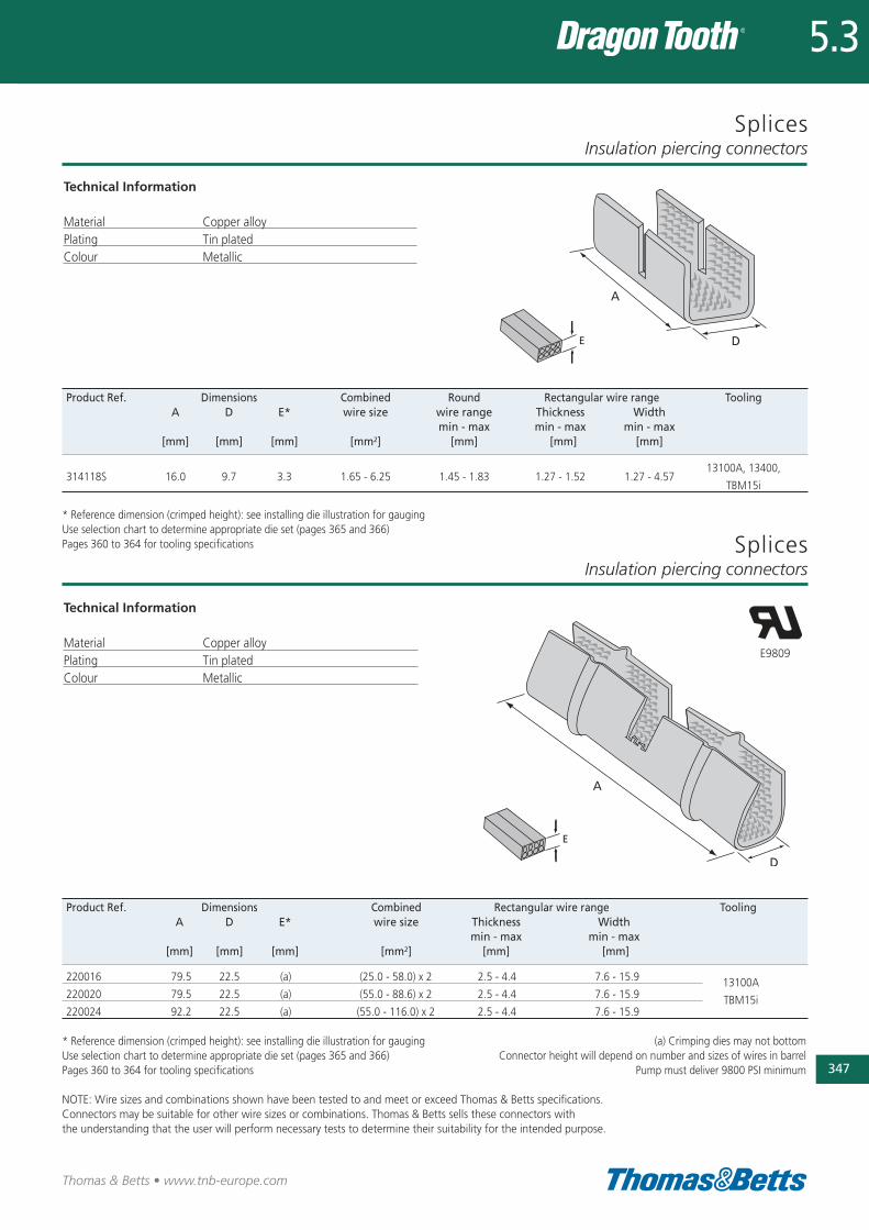
Splices
Technical Information
Material Copper alloyPlating Tin platedColour Metallic
Insulation piercing connectors
Thomas & Betts • www.tnb-europe.com
5.3
347
Product Ref. Dimensions Combined Round Rectangular wire range ToolingA D E* wire size wire range Thickness Width
min - max min - max min - max[mm] [mm] [mm] [mm2] [mm] [mm] [mm]
314118S 16.0 9.7 3.3 1.65 - 6.25 1.45 - 1.83 1.27 - 1.52 1.27 - 4.5713100A, 13400,
TBM15i
* Reference dimension (crimped height): see installing die illustration for gaugingUse selection chart to determine appropriate die set (pages 365 and 366)Pages 360 to 364 for tooling specifications
Product Ref. Dimensions Combined Rectangular wire range ToolingA D E* wire size Thickness Width
min - max min - max [mm] [mm] [mm] [mm2] [mm] [mm]
220016 79.5 22.5 (a) (25.0 - 58.0) x 2 2.5 - 4.4 7.6 - 15.9 13100A220020 79.5 22.5 (a) (55.0 - 88.6) x 2 2.5 - 4.4 7.6 - 15.9 TBM15i220024 92.2 22.5 (a) (55.0 - 116.0) x 2 2.5 - 4.4 7.6 - 15.9
* Reference dimension (crimped height): see installing die illustration for gaugingUse selection chart to determine appropriate die set (pages 365 and 366)Pages 360 to 364 for tooling specifications
NOTE: Wire sizes and combinations shown have been tested to and meet or exceed Thomas & Betts specifications. Connectors may be suitable for other wire sizes or combinations. Thomas & Betts sells these connectors with the understanding that the user will perform necessary tests to determine their suitability for the intended purpose.
E9809
(a) Crimping dies may not bottomConnector height will depend on number and sizes of wires in barrel
Pump must deliver 9800 PSI minimum
Technical Information
Material Copper alloyPlating Tin platedColour Metallic
SplicesInsulation piercing connectors
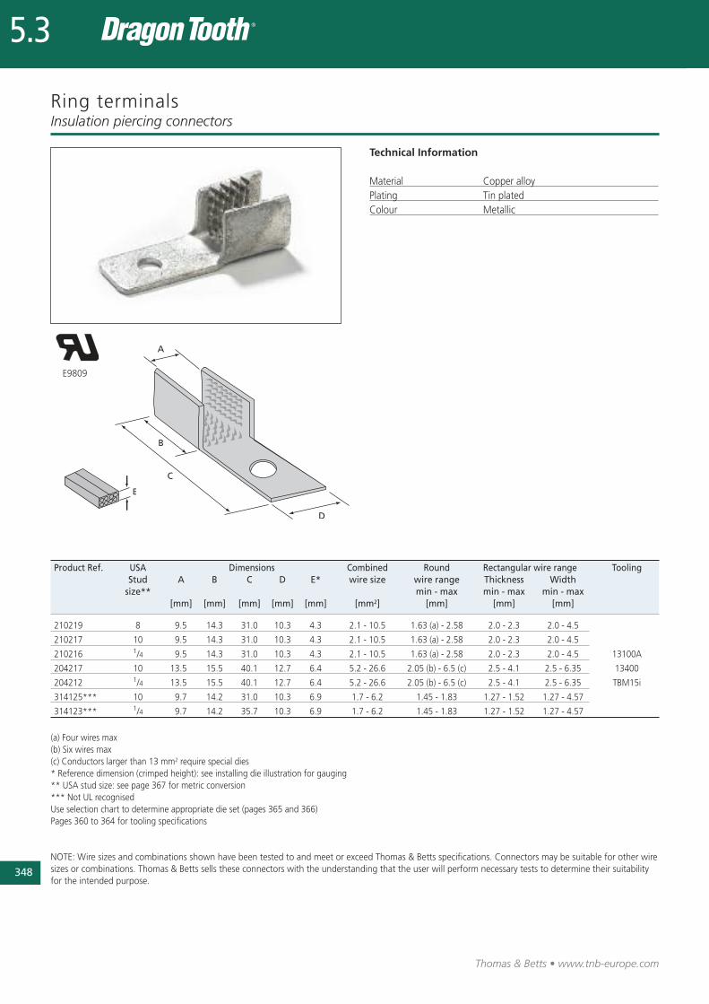
348
Thomas & Betts • www.tnb-europe.com
5.3
Ring terminalsInsulation piercing connectors
Product Ref. USA Dimensions Combined Round Rectangular wire range ToolingStud A B C D E* wire size wire range Thickness Width
size** min - max min - max min - max [mm] [mm] [mm] [mm] [mm] [mm2] [mm] [mm] [mm]
210219 8 9.5 14.3 31.0 10.3 4.3 2.1 - 10.5 1.63 (a) - 2.58 2.0 - 2.3 2.0 - 4.5
210217 10 9.5 14.3 31.0 10.3 4.3 2.1 - 10.5 1.63 (a) - 2.58 2.0 - 2.3 2.0 - 4.5
210216 1/4 9.5 14.3 31.0 10.3 4.3 2.1 - 10.5 1.63 (a) - 2.58 2.0 - 2.3 2.0 - 4.5 13100A
204217 10 13.5 15.5 40.1 12.7 6.4 5.2 - 26.6 2.05 (b) - 6.5 (c) 2.5 - 4.1 2.5 - 6.35 13400
204212 1/4 13.5 15.5 40.1 12.7 6.4 5.2 - 26.6 2.05 (b) - 6.5 (c) 2.5 - 4.1 2.5 - 6.35 TBM15i
314125*** 10 9.7 14.2 31.0 10.3 6.9 1.7 - 6.2 1.45 - 1.83 1.27 - 1.52 1.27 - 4.57
314123*** 1/4 9.7 14.2 35.7 10.3 6.9 1.7 - 6.2 1.45 - 1.83 1.27 - 1.52 1.27 - 4.57
(a) Four wires max(b) Six wires max (c) Conductors larger than 13 mm2 require special dies* Reference dimension (crimped height): see installing die illustration for gauging** USA stud size: see page 367 for metric conversion*** Not UL recognisedUse selection chart to determine appropriate die set (pages 365 and 366)Pages 360 to 364 for tooling specifications
NOTE: Wire sizes and combinations shown have been tested to and meet or exceed Thomas & Betts specifications. Connectors may be suitable for other wiresizes or combinations. Thomas & Betts sells these connectors with the understanding that the user will perform necessary tests to determine their suitabilityfor the intended purpose.
Technical Information
Material Copper alloyPlating Tin platedColour Metallic
E9809
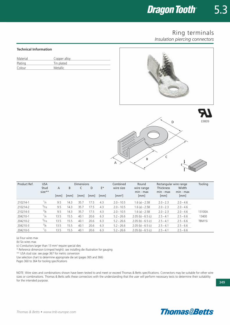
Ring terminals
Technical Information
Material Copper alloyPlating Tin platedColour Metallic
Insulation piercing connectors
349
Thomas & Betts • www.tnb-europe.com
5.3
E9809
Product Ref. USA Dimensions Combined Round Rectangular wire range ToolingStud A B C D E* wire size wire range Thickness Width
size** min - max min - max min - max [mm] [mm] [mm] [mm] [mm] [mm2] [mm] [mm] [mm]
210214-1 1/4 9.5 14.3 35.7 17.5 4.3 2.0 - 10.5 1.6 (a) - 2.58 2.0 - 2.3 2.0 - 4.6
210214-2 5/16 9.5 14.3 35.7 17.5 4.3 2.0 - 10.5 1.6 (a) - 2.58 2.0 - 2.3 2.0 - 4.6
210214-3 3/8 9.5 14.3 35.7 17.5 4.3 2.0 - 10.5 1.6 (a) - 2.58 2.0 - 2.3 2.0 - 4.6 13100A
204210-1 1/4 13.5 15.5 40.1 20.6 6.3 5.2 - 26.6 2.05 (b) - 6.5 (c) 2.5 - 4.1 2.5 - 6.6 13400
204210-2 5/16 13.5 15.5 40.1 20.6 6.3 5.2 - 26.6 2.05 (b) - 6.5 (c) 2.5 - 4.1 2.5 - 6.6 TBM15i
204210-3 3/8 13.5 15.5 40.1 20.6 6.3 5.2 - 26.6 2.05 (b) - 6.5 (c) 2.5 - 4.1 2.5 - 6.6
204210-5 1/2 13.5 15.5 40.1 20.6 6.3 5.2 - 26.6 2.05 (b) - 6.5 (c) 2.5 - 4.1 2.5 - 6.6
(a) Four wires max(b) Six wires max(c) Conductors larger than 13 mm2 require special dies* Reference dimension (crimped height): see installing die illustration for gauging** USA stud size: see page 367 for metric conversionUse selection chart to determine appropriate die set (pages 365 and 366)Pages 360 to 364 for tooling specifications
NOTE: Wire sizes and combinations shown have been tested to and meet or exceed Thomas & Betts specifications. Connectors may be suitable for other wiresizes or combinations. Thomas & Betts sells these connectors with the understanding that the user will perform necessary tests to determine their suitabilityfor the intended purpose.
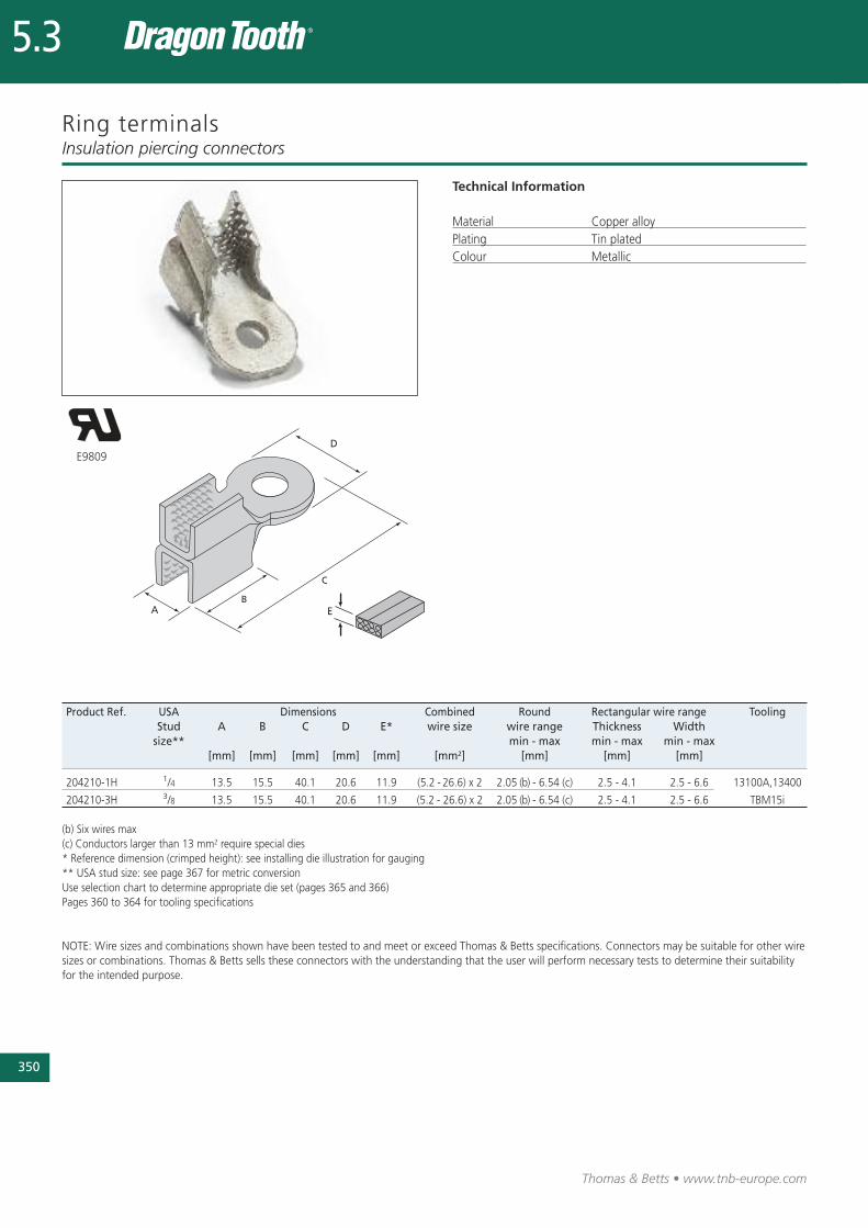
350
Thomas & Betts • www.tnb-europe.com
5.3
Ring terminals
Technical Information
Material Copper alloyPlating Tin platedColour Metallic
Insulation piercing connectors
Product Ref. USA Dimensions Combined Round Rectangular wire range ToolingStud A B C D E* wire size wire range Thickness Width
size** min - max min - max min - max [mm] [mm] [mm] [mm] [mm] [mm2] [mm] [mm] [mm]
204210-1H 1/4 13.5 15.5 40.1 20.6 11.9 (5.2 - 26.6) x 2 2.05 (b) - 6.54 (c) 2.5 - 4.1 2.5 - 6.6 13100A,13400
204210-3H 3/8 13.5 15.5 40.1 20.6 11.9 (5.2 - 26.6) x 2 2.05 (b) - 6.54 (c) 2.5 - 4.1 2.5 - 6.6 TBM15i
(b) Six wires max(c) Conductors larger than 13 mm2 require special dies * Reference dimension (crimped height): see installing die illustration for gauging** USA stud size: see page 367 for metric conversionUse selection chart to determine appropriate die set (pages 365 and 366)Pages 360 to 364 for tooling specifications
NOTE: Wire sizes and combinations shown have been tested to and meet or exceed Thomas & Betts specifications. Connectors may be suitable for other wiresizes or combinations. Thomas & Betts sells these connectors with the understanding that the user will perform necessary tests to determine their suitabilityfor the intended purpose.
E9809
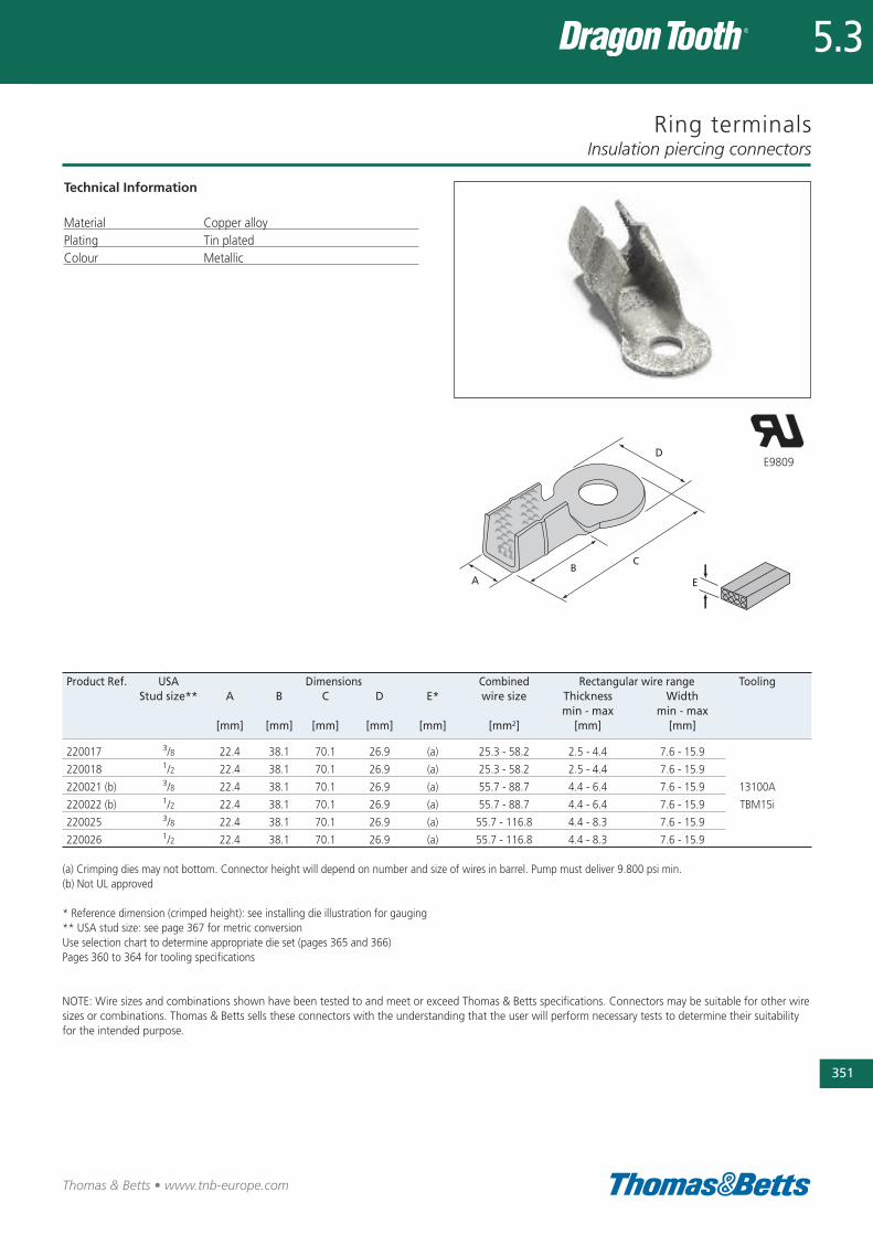
Ring terminals
Technical Information
Material Copper alloyPlating Tin platedColour Metallic
Insulation piercing connectors
351
Thomas & Betts • www.tnb-europe.com
5.3
Product Ref. USA Dimensions Combined Rectangular wire range ToolingStud size** A B C D E* wire size Thickness Width
min - max min - max [mm] [mm] [mm] [mm] [mm] [mm2] [mm] [mm]
220017 3/8 22.4 38.1 70.1 26.9 (a) 25.3 - 58.2 2.5 - 4.4 7.6 - 15.9
220018 1/2 22.4 38.1 70.1 26.9 (a) 25.3 - 58.2 2.5 - 4.4 7.6 - 15.9
220021 (b) 3/8 22.4 38.1 70.1 26.9 (a) 55.7 - 88.7 4.4 - 6.4 7.6 - 15.9 13100A
220022 (b) 1/2 22.4 38.1 70.1 26.9 (a) 55.7 - 88.7 4.4 - 6.4 7.6 - 15.9 TBM15i
220025 3/8 22.4 38.1 70.1 26.9 (a) 55.7 - 116.8 4.4 - 8.3 7.6 - 15.9
220026 1/2 22.4 38.1 70.1 26.9 (a) 55.7 - 116.8 4.4 - 8.3 7.6 - 15.9
(a) Crimping dies may not bottom. Connector height will depend on number and size of wires in barrel. Pump must deliver 9.800 psi min.(b) Not UL approved
* Reference dimension (crimped height): see installing die illustration for gauging ** USA stud size: see page 367 for metric conversionUse selection chart to determine appropriate die set (pages 365 and 366)Pages 360 to 364 for tooling specifications
NOTE: Wire sizes and combinations shown have been tested to and meet or exceed Thomas & Betts specifications. Connectors may be suitable for other wiresizes or combinations. Thomas & Betts sells these connectors with the understanding that the user will perform necessary tests to determine their suitabilityfor the intended purpose.
E9809
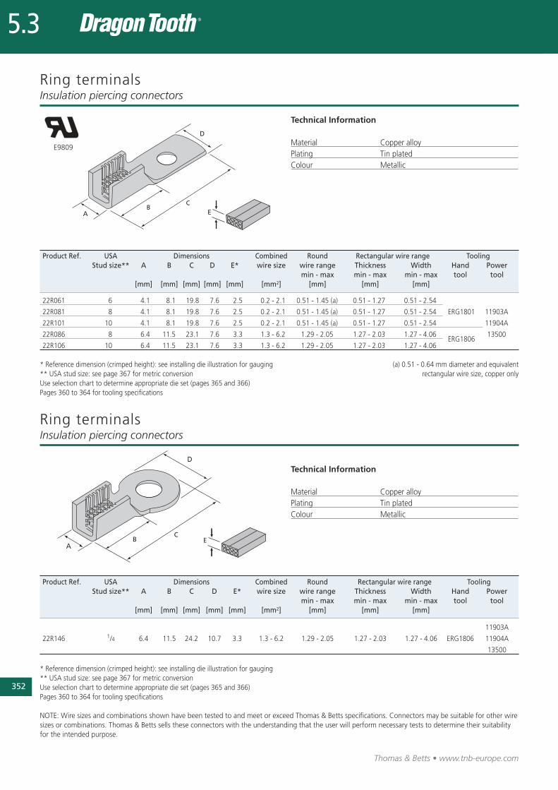
352
Thomas & Betts • www.tnb-europe.com
5.3
Ring terminals
Technical Information
Material Copper alloyPlating Tin platedColour Metallic
Insulation piercing connectors
Product Ref. USA Dimensions Combined Round Rectangular wire range ToolingStud size** A B C D E* wire size wire range Thickness Width Hand Power
min - max min - max min - max tool tool[mm] [mm] [mm] [mm] [mm] [mm2] [mm] [mm] [mm]
22R061 6 4.1 8.1 19.8 7.6 2.5 0.2 - 2.1 0.51 - 1.45 (a) 0.51 - 1.27 0.51 - 2.54
22R081 8 4.1 8.1 19.8 7.6 2.5 0.2 - 2.1 0.51 - 1.45 (a) 0.51 - 1.27 0.51 - 2.54 ERG1801 11903A
22R101 10 4.1 8.1 19.8 7.6 2.5 0.2 - 2.1 0.51 - 1.45 (a) 0.51 - 1.27 0.51 - 2.54 11904A
22R086 8 6.4 11.5 23.1 7.6 3.3 1.3 - 6.2 1.29 - 2.05 1.27 - 2.03 1.27 - 4.06ERG1806
13500
22R106 10 6.4 11.5 23.1 7.6 3.3 1.3 - 6.2 1.29 - 2.05 1.27 - 2.03 1.27 - 4.06
* Reference dimension (crimped height): see installing die illustration for gauging (a) 0.51 - 0.64 mm diameter and equivalent** USA stud size: see page 367 for metric conversion rectangular wire size, copper only Use selection chart to determine appropriate die set (pages 365 and 366)Pages 360 to 364 for tooling specifications
Product Ref. USA Dimensions Combined Round Rectangular wire range ToolingStud size** A B C D E* wire size wire range Thickness Width Hand Power
min - max min - max min - max tool tool[mm] [mm] [mm] [mm] [mm] [mm2] [mm] [mm] [mm]
11903A
22R146 1/4 6.4 11.5 24.2 10.7 3.3 1.3 - 6.2 1.29 - 2.05 1.27 - 2.03 1.27 - 4.06 ERG1806 11904A
13500
* Reference dimension (crimped height): see installing die illustration for gauging** USA stud size: see page 367 for metric conversionUse selection chart to determine appropriate die set (pages 365 and 366)Pages 360 to 364 for tooling specifications
NOTE: Wire sizes and combinations shown have been tested to and meet or exceed Thomas & Betts specifications. Connectors may be suitable for other wiresizes or combinations. Thomas & Betts sells these connectors with the understanding that the user will perform necessary tests to determine their suitabilityfor the intended purpose.
E9809
Ring terminalsInsulation piercing connectors
Technical Information
Material Copper alloyPlating Tin platedColour Metallic
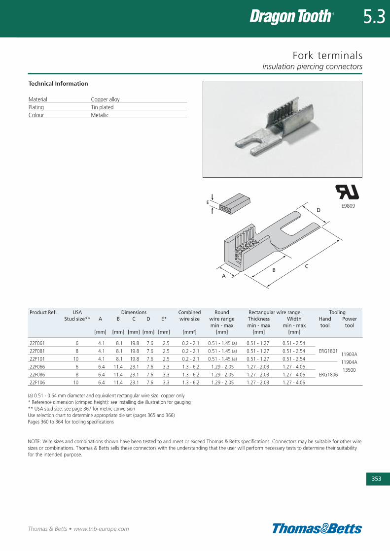
Fork terminals
Technical Information
Material Copper alloyPlating Tin platedColour Metallic
Insulation piercing connectors
353
Thomas & Betts • www.tnb-europe.com
5.3
Product Ref. USA Dimensions Combined Round Rectangular wire range ToolingStud size** A B C D E* wire size wire range Thickness Width Hand Power
min - max min - max min - max tool tool[mm] [mm] [mm] [mm] [mm] [mm2] [mm] [mm] [mm]
22F061 6 4.1 8.1 19.8 7.6 2.5 0.2 - 2.1 0.51 - 1.45 (a) 0.51 - 1.27 0.51 - 2.54
22F081 8 4.1 8.1 19.8 7.6 2.5 0.2 - 2.1 0.51 - 1.45 (a) 0.51 - 1.27 0.51 - 2.54 ERG180111903A
22F101 10 4.1 8.1 19.8 7.6 2.5 0.2 - 2.1 0.51 - 1.45 (a) 0.51 - 1.27 0.51 - 2.5411904A
22F066 6 6.4 11.4 23.1 7.6 3.3 1.3 - 6.2 1.29 - 2.05 1.27 - 2.03 1.27 - 4.0613500
22F086 8 6.4 11.4 23.1 7.6 3.3 1.3 - 6.2 1.29 - 2.05 1.27 - 2.03 1.27 - 4.06 ERG1806
22F106 10 6.4 11.4 23.1 7.6 3.3 1.3 - 6.2 1.29 - 2.05 1.27 - 2.03 1.27 - 4.06
(a) 0.51 - 0.64 mm diameter and equivalent rectangular wire size, copper only* Reference dimension (crimped height): see installing die illustration for gauging** USA stud size: see page 367 for metric conversionUse selection chart to determine appropriate die set (pages 365 and 366)Pages 360 to 364 for tooling specifications
NOTE: Wire sizes and combinations shown have been tested to and meet or exceed Thomas & Betts specifications. Connectors may be suitable for other wiresizes or combinations. Thomas & Betts sells these connectors with the understanding that the user will perform necessary tests to determine their suitabilityfor the intended purpose.
E9809
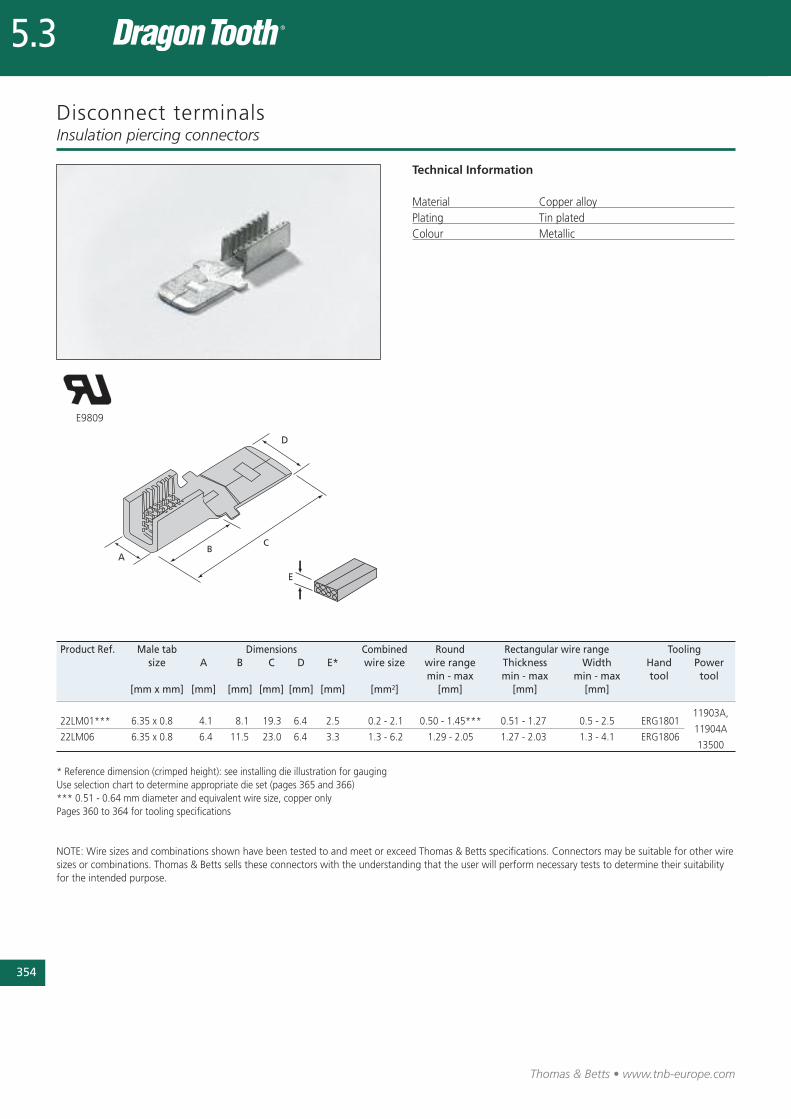
354
Thomas & Betts • www.tnb-europe.com
5.3
Disconnect terminals
Technical Information
Material Copper alloyPlating Tin platedColour Metallic
Insulation piercing connectors
Product Ref. Male tab Dimensions Combined Round Rectangular wire range Toolingsize A B C D E* wire size wire range Thickness Width Hand Power
min - max min - max min - max tool tool[mm x mm] [mm] [mm] [mm] [mm] [mm] [mm2] [mm] [mm] [mm]
11903A, 22LM01*** 6.35 x 0.8 4.1 8.1 19.3 6.4 2.5 0.2 - 2.1 0.50 - 1.45*** 0.51 - 1.27 0.5 - 2.5 ERG1801
11904A22LM06 6.35 x 0.8 6.4 11.5 23.0 6.4 3.3 1.3 - 6.2 1.29 - 2.05 1.27 - 2.03 1.3 - 4.1 ERG1806
13500
* Reference dimension (crimped height): see installing die illustration for gaugingUse selection chart to determine appropriate die set (pages 365 and 366)*** 0.51 - 0.64 mm diameter and equivalent wire size, copper onlyPages 360 to 364 for tooling specifications
NOTE: Wire sizes and combinations shown have been tested to and meet or exceed Thomas & Betts specifications. Connectors may be suitable for other wiresizes or combinations. Thomas & Betts sells these connectors with the understanding that the user will perform necessary tests to determine their suitabilityfor the intended purpose.
E9809
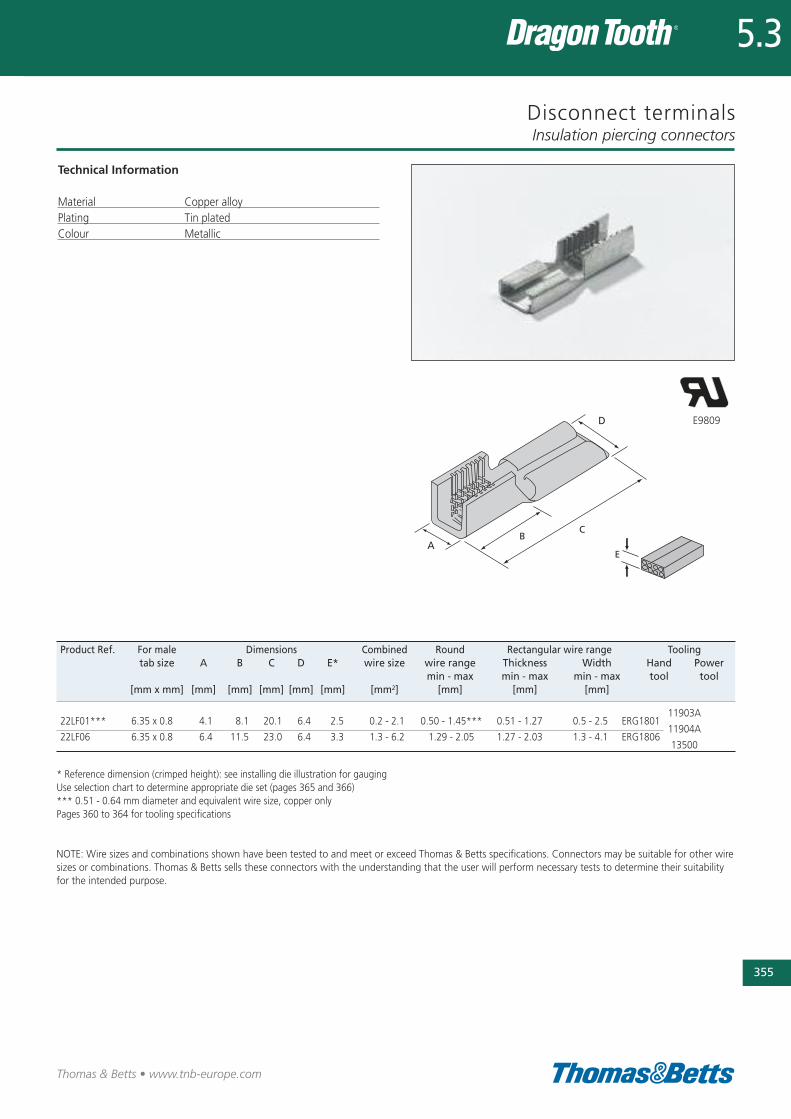
Disconnect terminals
Technical Information
Material Copper alloyPlating Tin platedColour Metallic
Insulation piercing connectors
355
Thomas & Betts • www.tnb-europe.com
5.3
Product Ref. For male Dimensions Combined Round Rectangular wire range Toolingtab size A B C D E* wire size wire range Thickness Width Hand Power
min - max min - max min - max tool tool[mm x mm] [mm] [mm] [mm] [mm] [mm] [mm2] [mm] [mm] [mm]
11903A22LF01*** 6.35 x 0.8 4.1 8.1 20.1 6.4 2.5 0.2 - 2.1 0.50 - 1.45*** 0.51 - 1.27 0.5 - 2.5 ERG1801
11904A22LF06 6.35 x 0.8 6.4 11.5 23.0 6.4 3.3 1.3 - 6.2 1.29 - 2.05 1.27 - 2.03 1.3 - 4.1 ERG1806
13500
* Reference dimension (crimped height): see installing die illustration for gaugingUse selection chart to determine appropriate die set (pages 365 and 366)*** 0.51 - 0.64 mm diameter and equivalent wire size, copper onlyPages 360 to 364 for tooling specifications
NOTE: Wire sizes and combinations shown have been tested to and meet or exceed Thomas & Betts specifications. Connectors may be suitable for other wiresizes or combinations. Thomas & Betts sells these connectors with the understanding that the user will perform necessary tests to determine their suitabilityfor the intended purpose.
E9809
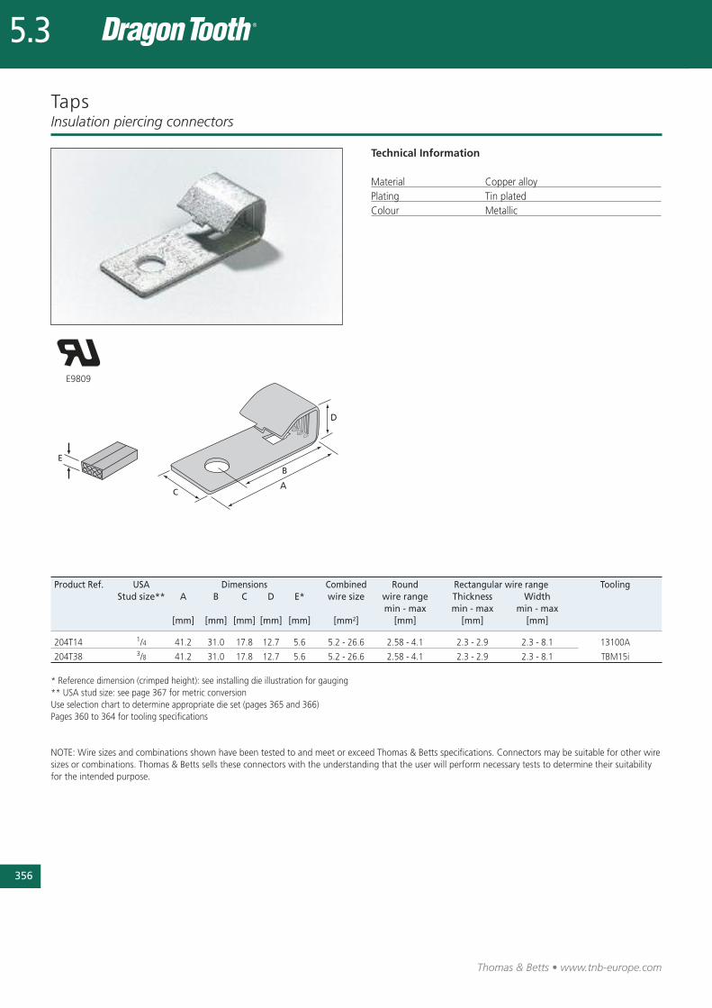
356
Thomas & Betts • www.tnb-europe.com
5.3
Taps
Technical Information
Material Copper alloyPlating Tin platedColour Metallic
Insulation piercing connectors
E9809
Product Ref. USA Dimensions Combined Round Rectangular wire range ToolingStud size** A B C D E* wire size wire range Thickness Width
min - max min - max min - max [mm] [mm] [mm] [mm] [mm] [mm2] [mm] [mm] [mm]
204T14 1/4 41.2 31.0 17.8 12.7 5.6 5.2 - 26.6 2.58 - 4.1 2.3 - 2.9 2.3 - 8.1 13100A
204T38 3/8 41.2 31.0 17.8 12.7 5.6 5.2 - 26.6 2.58 - 4.1 2.3 - 2.9 2.3 - 8.1 TBM15i
* Reference dimension (crimped height): see installing die illustration for gauging** USA stud size: see page 367 for metric conversionUse selection chart to determine appropriate die set (pages 365 and 366)Pages 360 to 364 for tooling specifications
NOTE: Wire sizes and combinations shown have been tested to and meet or exceed Thomas & Betts specifications. Connectors may be suitable for other wiresizes or combinations. Thomas & Betts sells these connectors with the understanding that the user will perform necessary tests to determine their suitabilityfor the intended purpose.

Modular connectors
Technical Information
Material Copper alloyPlating Tin platedColour Metallic
Insulation piercing connectors
357
Thomas & Betts • www.tnb-europe.com
5.3
E9809
Product Ref. Dimensions Combined Round Rectangular wire range ToolingA D E* wire size** wire range Thickness Width
min - max min - max min - max[mm] [mm] [mm] [mm2] [mm] [mm] [mm]
2.0 - 3.8 (upper half) 2.0 - 12.4 (upper half) 13100A210214MT 16.0 19.1 (a) 10.1 - 53.2 1.8 - 4.62
6.4 max. (lower half) 19.1 max. (lower half) 13400, TBM15i
2.5 - 6.8 (upper half) 2.5 - 23.4 (upper half)204210MT 23.8 26.2 (a) 45.6 - 108.9 2.6 - 5.84
6.4 max. (lower half) 26.2 max. (lower half)13400
* Reference dimension (crimped height): see installing die illustration for gauging(a) Crimping dies may not bottom. Connector height will depend on number and size of wires in barrel. Pump must deliver 9.800 psi min.** combined wire size is for the whole connector (including upper half and lower half)Use selection chart to determine appropriate die set (pages 365 and 366)Pages 360 to 364 for tooling specifications
NOTE: Wire sizes and combinations shown have been tested to and meet or exceed Thomas & Betts specifications. Connectors may be suitable for other wiresizes or combinations. Thomas & Betts sells these connectors with the understanding that the user will perform necessary tests to determine their suitabilityfor the intended purpose.

358
Thomas & Betts • www.tnb-europe.com
5.3
Modular connectors
Technical Information
Material Copper alloyPlating Tin platedColour Metallic
Insulation piercing connectors
Product Ref. USA Dimensions DescriptionStud size* A B1 B2 C1 C2 D E
[mm] [mm] [mm] [mm] [mm] [mm] [mm]
210MT14 1/4 25.4 36.3 52.1 15.9 20.6 - 2.0 Screw-on clip for connectors 210214MT
210MT38 3/8 25.4 36.3 52.1 15.9 20.6 - 2.0 Screw-on clip for connectors 210214MT
204MT14 1/4 25.4 36.8 55.4 23.2 23.2 28.6 2.5 Screw-on clip for connectors 204210MT
204MT38 3/8 25.4 36.8 55.4 23.2 23.2 28.6 2.5 Screw-on clip for connectors 204210MT
* USA stud size: see page 367 for metric conversion
NOTE: Wire sizes and combinations shown have been tested to and meet or exceed Thomas & Betts specifications. Connectors may be suitable for other wiresizes or combinations. Thomas & Betts sells these connectors with the understanding that the user will perform necessary tests to determine their suitabilityfor the intended purpose.
E9809
210MT14210MT38
204MT14204MT38
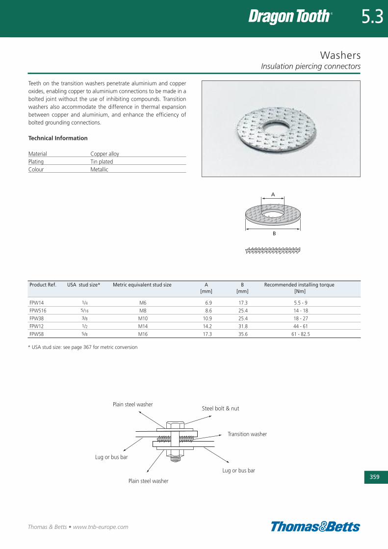
Washers
Teeth on the transition washers penetrate aluminium and copperoxides, enabling copper to aluminium connections to be made in abolted joint without the use of inhibiting compounds. Transitionwashers also accommodate the difference in thermal expansionbetween copper and aluminium, and enhance the efficiency ofbolted grounding connections.
Technical Information
Material Copper alloyPlating Tin platedColour Metallic
Insulation piercing connectors
359
Thomas & Betts • www.tnb-europe.com
5.3
Product Ref. USA stud size* Metric equivalent stud size A B Recommended installing torque[mm] [mm] [Nm]
FPW14 1/4 M6 6.9 17.3 5.5 - 9
FPW516 5/16 M8 8.6 25.4 14 - 18
FPW38 3/8 M10 10.9 25.4 18 - 27
FPW12 1/2 M14 14.2 31.8 44 - 61
FPW58 5/8 M16 17.3 35.6 61 - 82.5
* USA stud size: see page 367 for metric conversion
Plain steel washer
Plain steel washer
Lug or bus bar
Steel bolt & nut
Transition washer
Lug or bus bar
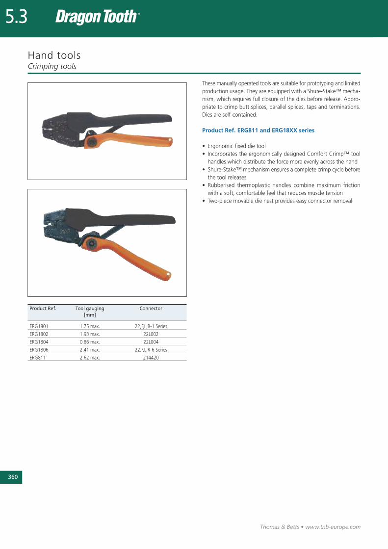
360
Thomas & Betts • www.tnb-europe.com
5.3
Hand tools
These manually operated tools are suitable for prototyping and limitedproduction usage. They are equipped with a Shure-Stake™ mecha-nism, which requires full closure of the dies before release. Appro-priate to crimp butt splices, parallel splices, taps and terminations.Dies are self-contained.
Product Ref. ERG811 and ERG18XX series
• Ergonomic fixed die tool• Incorporates the ergonomically designed Comfort Crimp™ toolhandles which distribute the force more evenly across the hand
• Shure-Stake™ mechanism ensures a complete crimp cycle beforethe tool releases
• Rubberised thermoplastic handles combine maximum frictionwith a soft, comfortable feel that reduces muscle tension
• Two-piece movable die nest provides easy connector removal
Crimping tools
Product Ref. Tool gauging Connector[mm]
ERG1801 1.75 max. 22,F,L,R-1 Series
ERG1802 1.93 max. 22L002
ERG1804 0.86 max. 22L004
ERG1806 2.41 max. 22,F,L,R-6 Series
ERG811 2.62 max. 214420
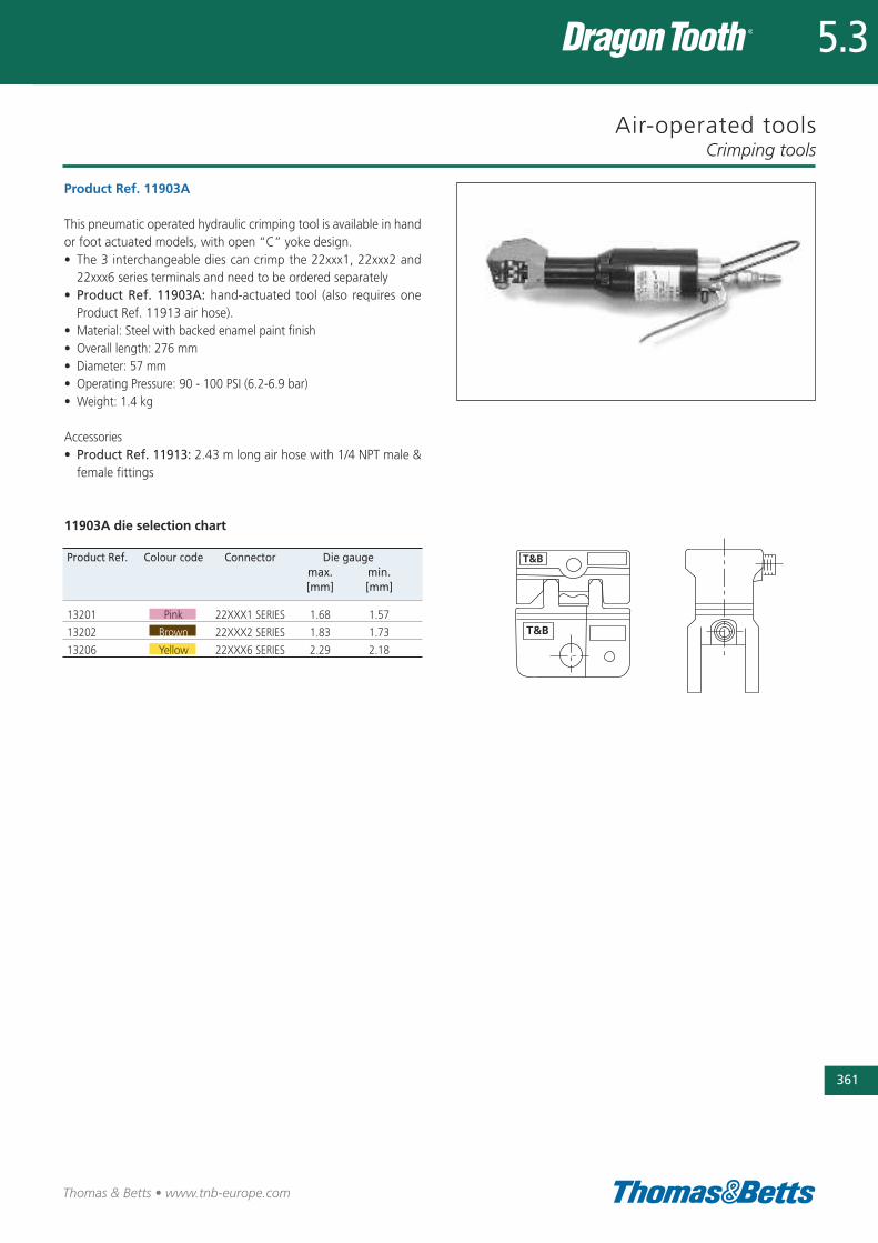
Air-operated tools
Product Ref. 11903A
This pneumatic operated hydraulic crimping tool is available in handor foot actuated models, with open “C” yoke design.• The 3 interchangeable dies can crimp the 22xxx1, 22xxx2 and22xxx6 series terminals and need to be ordered separately
• Product Ref. 11903A: hand-actuated tool (also requires oneProduct Ref. 11913 air hose).
• Material: Steel with backed enamel paint finish• Overall length: 276 mm• Diameter: 57 mm• Operating Pressure: 90 - 100 PSI (6.2-6.9 bar)• Weight: 1.4 kg
Accessories• Product Ref. 11913: 2.43 m long air hose with 1/4 NPT male &female fittings
11903A die selection chart
Crimping tools
361
Thomas & Betts • www.tnb-europe.com
5.3
Product Ref. Colour code Connector Die gaugemax. min.[mm] [mm]
13201 Pink 22XXX1 SERIES 1.68 1.57
13202 Brown 22XXX2 SERIES 1.83 1.73
13206 Yellow 22XXX6 SERIES 2.29 2.18

362
Thomas & Betts • www.tnb-europe.com
5.3
Auto-feed tools for connectors on strip
Pneumatic bench mounted foot operated tool for crimping copperor aluminium magnet wire and copper lead wire, not solder dippedor bonded.
• Operates on min. 85 psi, 6.0 bar air supply• Foot pedal contains T&B Shure-Stake™ control mechanism whichensures a full compression each time
• Insulation piercing connectors are fed on a continuous reelmounted strip
• Dies are self-contained. Includes foot valve, hoses and air treat-ment system
Crimping tools
Product Ref. Connector Connector Tool Tool Tool Toolproduct ref. qty per reel weight width depth height
[kg] [mm] [mm] [mm]
13676A 220004 9000 8.6 127 356 279
13678 220001 3000 12.7 152 457 356
13679 220002-TB 3000 12.7 152 457 356
13696 220006 2500 14.5 152 457 406
See page 341 for more information about the connectors on strip.
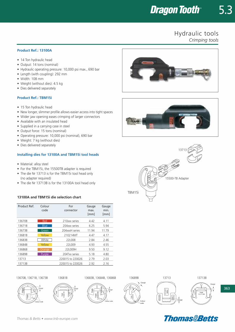
Hydraulic tools
Product Ref.: 13100A
• 14 Ton hydraulic head• Output: 14 tons (nominal)• Hydraulic operating pressure: 10,000 psi max., 690 bar• Length (with coupling): 292 mm• Width: 108 mm• Weight (without dies): 4.5 kg• Dies delivered separately
Product Ref.: TBM15i
• 15 Ton hydraulic head• New longer, slimmer profile allows easier access into tight spaces• Wider jaw opening eases crimping of larger connectors• Available with an insulated head• Supplied in a carrying case in steel• Output force: 15 tons (nominal)• Operating pressure: 10,000 psi (nominal), 690 bar• Weight: 7 kg (without dies)• Dies delivered separately
Installing dies for 13100A and TBM15i tool heads
• Material: alloy steel• For the TBM15i, the 15500TB adapter is required• The die Nr 13713 is for the TBM15i tool head only (no adapter required)
• The die Nr 13713B is for the 13100A tool head only
13100A and TBM15i die selection chart
Crimping tools
363
Thomas & Betts • www.tnb-europe.com
5.3
15500-TB Adapter
13713
TBM15i
Product Ref. Colour For Gauge Gaugecode connector max. min.
[mm] [mm]
13670B Red 210xxx series 4.42 4.11
13671B Blue 204xxx series 6.25 5.94
13673B Green 204xxxH series 11.94 11.79
13681B Yellow 210214MT 4.47 4.17
13683B White 22L008 2.84 2.46
13684B Yellow 22L009 4.93 4.55
13686B Orange 22L009H 9.50 9.12
13689B Purple 204Txx series 5.18 4.80
13713 220015 to 220026 2.79 2.03
13713B 220015 to 220026 2.92 2.16
13670B, 13671B, 13673B 13681B 13683B, 13684B, 13686B 13689B 13713 13713B
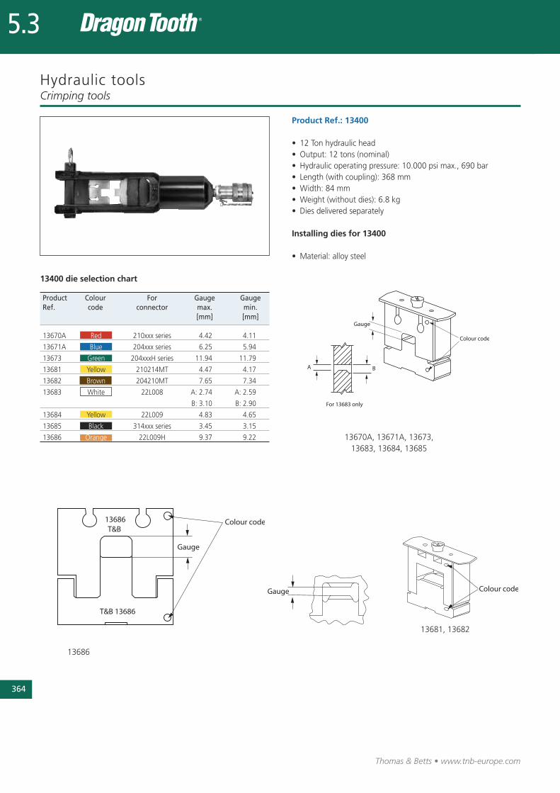
Thomas & Betts • www.tnb-europe.com
5.3
Hydraulic tools
Product Ref.: 13400
• 12 Ton hydraulic head• Output: 12 tons (nominal)• Hydraulic operating pressure: 10.000 psi max., 690 bar• Length (with coupling): 368 mm• Width: 84 mm• Weight (without dies): 6.8 kg• Dies delivered separately
Installing dies for 13400
• Material: alloy steel
Crimping tools
Product Colour For Gauge GaugeRef. code connector max. min.
[mm] [mm]
13670A Red 210xxx series 4.42 4.11
13671A Blue 204xxx series 6.25 5.94
13673 Green 204xxxH series 11.94 11.79
13681 Yellow 210214MT 4.47 4.17
13682 Brown 204210MT 7.65 7.34
13683 White 22L008 A: 2.74 A: 2.59
B: 3.10 B: 2.90
13684 Yellow 22L009 4.83 4.65
13685 Black 314xxx series 3.45 3.15
13686 Orange 22L009H 9.37 9.22
13686
13670A, 13671A, 13673, 13683, 13684, 13685
13681, 13682
364
13400 die selection chart

Connectors, tool and die selection chartCrimping tools
365
Thomas & Betts • www.tnb-europe.com
5.3
Hand tools Pneumatic tools Auto-feed tool for 14 ton 12 ton 15 ton(fixed die) 11903A magnet wire on hydraulic head hydraulic head hydraulic head
strip 13100A 13400 TBM15i
TERMINALS TOOL DIE TOOL DIE DIE DIE + ADAPTOR
204210MT – – – – 13682 –
204210S – – – 13671B 13671A 13671B with 15500TB
204210SH – – – 13673B 13673 13673B with 15500TB
204210-1 – – – 13671B 13671A 13671B with 15500TB
204210-1H – – – 13673B 13673 13673B with 15500TB
204210-2 – – – 13671B 13671A 13671B with 15500TB
204210-3 – – – 13671B 13671A 13671B with 15500TB
204210-3H – – – 13673B 13673 13673B with 15500TB
204201-5 – – – 13671B 13671A 13671B with 15500TB
204211 – – – 13671B 13671A 13671B with 15500TB
204212 – – – 13671B 13671A 13671B with 15500TB
204217 – – – 13671B 13671A 13671B with 15500TB
204MT14 – – – – – –
204MT38 – – – – – –
204T14 – – – 13689B – 13689B with 15500TB
204T38 – – – 13689B – 13689B with 15500TB
210214MT – – – 13681B 13681 13681B with 15500TB
210214S – – – 13670B 13670A 13670B with 15500TB
210214-1 – – – 13670B 13670A 13670B with 15500TB
210214-2 – – – 13670B 13670A 13670B with 15500TB
210214-3 – – – 13670B 13670A 13670B with 15500TB
210216 – – – 13670B 13670A 13670B with 15500TB
210217 – – – 13670B 13670A 13670B with 15500TB
210219 – – – 13670B 13670A 13670B with 15500TB
210MT14 – – – – – –
210MT38 – – – – – –
214420 ERG811 11956 – – – –
220001 – – 13678 – – –
220002-TB – – 13679 – – –
220004 – – 13676A – – –
220006 – – 13696 – – –
220015 – – – 13713B – 13713
220016 – – – 13713B – 13713
220017 – – – 13713B – 13713
220018 – – – 13713B – 13713
220019 – – – 13713B – 13713
220020 – – – 13713B – 13713
220021 – – – 13713B – 13713
220022 – – – 13713B – 13713
220023 – – – 13713B – 13713
220024 – – – 13713B – 13713
220025 – – – 13713B – 13713
220026 – – – 13713B – 13713
(continued on next page)

366
Thomas & Betts • www.tnb-europe.com
5.3
Connectors, tool and die selection chartCrimping tools
Hand tools Pneumatic tools Auto-feed tool for 14 ton 12 ton 15 ton(fixed die) 11903A magnet wire on hydraulic head hydraulic head hydraulic head
strip 13100A 13400 TBM15i
TERMINALS TOOL DIE TOOL DIE DIE DIE + ADAPTOR
22F061 ERG1801 13201 – – – –
22F066 ERG1806 13206 – – – –
22F081 ERG1801 13201 – – – –
22F086 ERG1806 13206 – – – –
22F101 ERG1801 13201 – – – –
22F106 ERG1806 13206 – – – –
22L001 ERG1801 13201 – – – –
22L002 ERG1802 13202 – – – –
22L004 ERG1804 – – – – –
22L006 ERG1806 13206 – – – –
22L008 – – – 13683B 13683 13683B with 15500TB
22L009 – – – 13684B 13684 13684B with 15500TB
22L009H – – – 13686B 13686 13686B with 15500TB
22LF01 ERG1801 13201 – – – –
22LF06 ERG1806 13206 – – – –
22LM01 ERG1801 13201 – – – –
22LM06 ERG1806 13206 – – – –
22R061 ERG1801 13201 – – – –
22R081 ERG1801 13201 – – – –
22R086 ERG1806 13206 – – – –
22R101 ERG1801 13201 – – – –
22R106 ERG1806 13206 – – – –
22R146 ERG1806 13206 – – – –
314118S – – – 13685B 13685 13685B with 15500TB
314123 – – – 13685B 13685 13685B with 15500TB
314125 – – – 13685B 13685 13685B with 15500TB
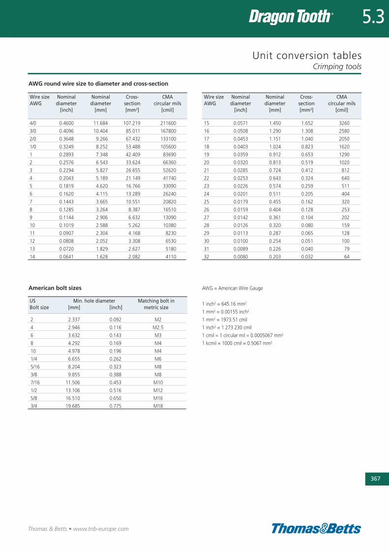
Unit conversion tables
AWG round wire size to diameter and cross-section
Crimping tools
367
Thomas & Betts • www.tnb-europe.com
Wire size Nominal Nominal Cross- CMAAWG diameter diameter section circular mils
[inch] [mm] [mm2] [cmil]
4/0 0.4600 11.684 107.219 211600
3/0 0.4096 10.404 85.011 167800
2/0 0.3648 9.266 67.432 133100
1/0 0.3249 8.252 53.488 105600
1 0.2893 7.348 42.409 83690
2 0.2576 6.543 33.624 66360
3 0.2294 5.827 26.655 52620
4 0.2043 5.189 21.149 41740
5 0.1819 4.620 16.766 33090
6 0.1620 4.115 13.289 26240
7 0.1443 3.665 10.551 20820
8 0.1285 3.264 8.387 16510
9 0.1144 2.906 6.632 13090
10 0.1019 2.588 5.262 10380
11 0.0907 2.304 4.168 8230
12 0.0808 2.052 3.308 6530
13 0.0720 1.829 2.627 5180
14 0.0641 1.628 2.082 4110
Wire size Nominal Nominal Cross- CMAAWG diameter diameter section circular mils
[inch] [mm] [mm2] [cmil]
15 0.0571 1.450 1.652 3260
16 0.0508 1.290 1.308 2580
17 0.0453 1.151 1.040 2050
18 0.0403 1.024 0.823 1620
19 0.0359 0.912 0.653 1290
20 0.0320 0.813 0.519 1020
21 0.0285 0.724 0.412 812
22 0.0253 0.643 0.324 640
23 0.0226 0.574 0.259 511
24 0.0201 0.511 0.205 404
25 0.0179 0.455 0.162 320
26 0.0159 0.404 0.128 253
27 0.0142 0.361 0.104 202
28 0.0126 0.320 0.080 159
29 0.0113 0.287 0.065 128
30 0.0100 0.254 0.051 100
31 0.0089 0.226 0.040 79
32 0.0080 0.203 0.032 64
American bolt sizes
US Min. hole diameter Matching bolt inBolt size [mm] [inch] metric size
2 2.337 0.092 M2
4 2.946 0.116 M2.5
6 3.632 0.143 M3
8 4.292 0.169 M4
10 4.978 0.196 M4
1/4 6.655 0.262 M6
5/16 8.204 0.323 M8
3/8 9.855 0.388 M8
7/16 11.506 0.453 M10
1/2 13.106 0.516 M12
5/8 16.510 0.650 M16
3/4 19.685 0.775 M18
5.3
AWG = American Wire Gauge
1 inch2 = 645.16 mm2
1 mm2 = 0.00155 inch2
1 mm2 = 1973.51 cmil
1 inch2 = 1 273 230 cmil
1 cmil = 1 circular mil = 0.0005067 mm2
1 kcmil = 1000 cmil = 0.5067 mm2

Thomas & Betts • www.tnb-europe.com
Shie ld-Kon ®
Solder less connectorsfor grounding shie lded
and coaxia l cables
368
5.4
369
Thomas & Betts • www.tnb-europe.com
5.4
TERMINATION SYSTEMS
5.1 STA-KON® - CRIMP TERMINALS 278
5.2 COLOR-KEYED® - POWER CABLE CONNECTORS 322
5.3 DRAGON TOOTH® - MAGNET WIRE TERMINALS 336
5.4 SHIELD-KON® - SHIELDED CABLE CONNECTORS 368
One-piece connector 372
Installation methods and procedures 372
Connectors 373
Selection gauge 374
Accessories: the RSK-FLAG connectors 374
Ergonomic hand tools 375
Two-piece connectors - Hexagonal Range 376
Installation methods 377
Connector and die selection 378
Tooling 379
Two-piece connectors - Circular Range 382
Installation method 382
Connector and die selection 383
Tooling 384
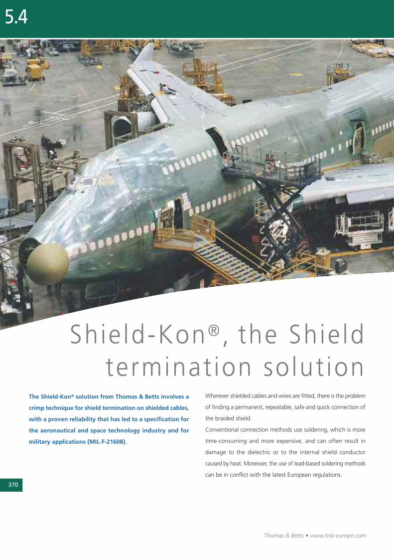
370
Thomas & Betts • www.tnb-europe.com
5.4
Shie ld-Kon ® , the Shie ld terminat ion solut ion
The Shield-Kon® solution from Thomas & Betts involves a
crimp technique for shield termination on shielded cables,
with a proven reliability that has led to a specification for
the aeronau tical and space technology industry and for
military applications (MIL-F-21608).
Wherever shielded cables and wires are fitted, there is the problem
of finding a permanent, repeatable, safe and quick connection of
the braided shield.
Conventional connection methods use soldering, which is more
time-consuming and more expensive, and can often result in
damage to the dielectric or to the internal shield conductor
caused by heat. Moreover, the use of lead-based soldering methods
can be in conflict with the latest European regulations.

371
Thomas & Betts • www.tnb-europe.com
5.4
The reliability of Shield-Kon®
terminals has led to a specification
for the aeronautical and
space technology industry and
for military applications
(MIL-F-21608).
Thomas & Betts offer two solutions:
The one-piece Shield-Kon® connector, which is wrapped
around the shield during the crimping process.
This solderless, wraparound connector terminates shielded cable
in seconds with uniform precision. It’s particularly well suited for
production work in aircraft, aerospace, and electronic industries
where size and weight are of importance.
Once crimped, it provides a compact, lightweight, low-resistance,
high-strength connection, which meets and exceeds the per-
formance requirements of MIL-F-21608.
The connector works equally well on braided, wrapped, or foil
shields and has the added advantage of being able to be used as
a mid-span termination.
Only four sizes, which can be easily identified by the colour of
their insulation, are needed to cover a range of shielding diameters
from 1.27 mm to 7.62 mm.
The two-piece Shield-Kon® connector, which consists of two
sleeves, between which the shielded braid and the drain
wire are compressed.
The Shield-Kon® two-piece shield termination system consists of
two cylindrical sleeves: an inner sleeve with a smaller diameter,
and an outer sleeve that has a larger diameter but is shorter and
less hard than the inner sleeve. All inner and outer sleeves are
colour-coded according to their size.
The conductors of the cable are inserted through the inner sleeve,
whereas the shield (braided or foiled) and the drain wire are
inserted between the two sleeves. The crimp operation is done
by compressing the outer sleeve with a tool, while the inner sleeve
ensures a mechanical protection to the inner conductors.
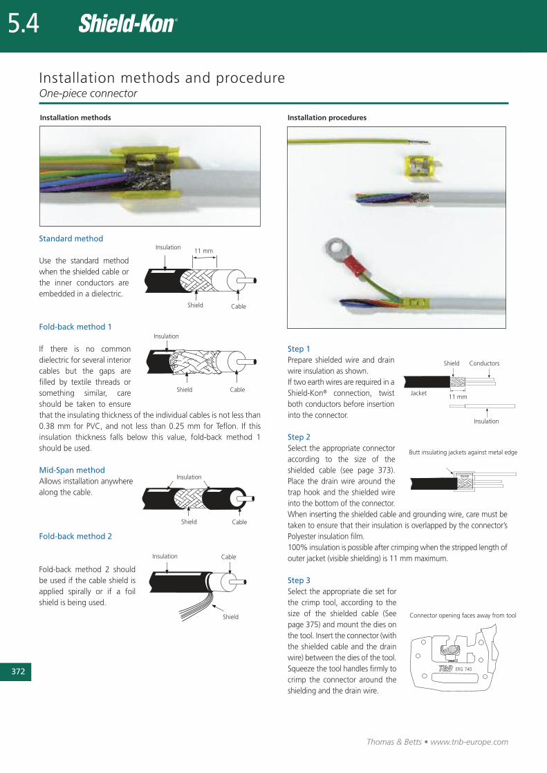
372
Thomas & Betts • www.tnb-europe.com
5.4
Installation methods and procedureOne-piece connector
Step 2Select the appropriate connectoraccording to the size of theshielded cable (see page 373).Place the drain wire around thetrap hook and the shielded wireinto the bottom of the connector.When inserting the shielded cable and grounding wire, care must betaken to ensure that their insulation is overlapped by the connector’sPolyester insulation film.100% insulation is possible after crimping when the stripped length ofouter jacket (visible shielding) is 11 mm maximum.
If there is no commondielectric for several inte riorcables but the gaps arefilled by textile threads orsomething similar, careshould be taken to ensurethat the insulating thick ness of the individual cables is not less than0.38 mm for PVC, and not less than 0.25 mm for Teflon. If thisinsulation thickness falls below this value, fold-back method 1should be used.
Mid-Span methodInsulation
Shield Cable
Insulation
Shield Cable
11 mm
Insulation
Shield Cable
Insulation
Shield
Cable
Standard method
Fold-back method 1
Fold-back method 2
Allows installation anywherealong the cable.
Use the standard methodwhen the shielded cable orthe inner conductors areembedded in a dielec tric.
Fold-back method 2 shouldbe used if the cable shield isapplied spirally or if a foilshield is being used.
Step 1Prepare shielded wire and drainwire insulation as shown. If two earth wires are required in aShield-Kon® connection, twistboth conductors before insertioninto the connector.
Shield Conductors
Jacket11 mm
Insulation
Butt insulating jackets against metal edge
Connector opening faces away from tool
Installation methods Installation procedures
Step 3Select the appropriate die set forthe crimp tool, according to thesize of the shielded cable (Seepage 375) and mount the dies onthe tool. Insert the connector (withthe shielded cable and the drainwire) between the dies of the tool.Squeeze the tool handles firmly tocrimp the connector around theshielding and the drain wire.
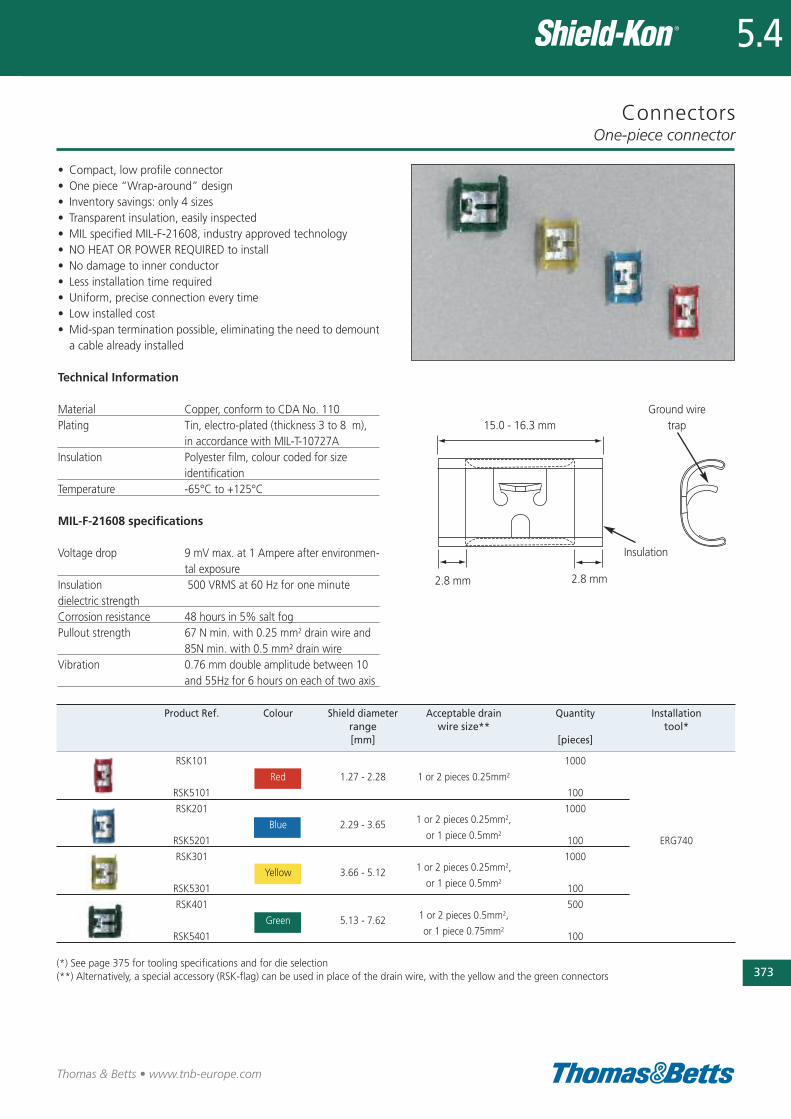
Connectors
• Compact, low profile connector• One piece “Wrap-around” design• Inventory savings: only 4 sizes• Transparent insulation, easily inspected• MIL specified MIL-F-21608, industry approved technology• NO HEAT OR POWER REQUIRED to install• No damage to inner conductor• Less installation time required• Uniform, precise connection every time• Low installed cost• Mid-span termination possible, eliminating the need to demounta cable already installed
Technical Information
Material Copper, conform to CDA No. 110Plating Tin, electro-plated (thickness 3 to 8 �m),
in accordance with MIL-T-10727AInsulation Polyester film, colour coded for size
identificationTemperature -65°C to +125°C
MIL-F-21608 specifications
Voltage drop 9 mV max. at 1 Ampere after environmen-tal exposure
Insulation 500 VRMS at 60 Hz for one minutedielectric strengthCorrosion resistance 48 hours in 5% salt fogPullout strength 67 N min. with 0.25 mm2 drain wire and
85N min. with 0.5 mm² drain wireVibration 0.76 mm double amplitude between 10
and 55Hz for 6 hours on each of two axis
One-piece connector
373
Thomas & Betts • www.tnb-europe.com
5.4
15.0 - 16.3 mm
2.8 mm 2.8 mm
Ground wiretrap
Insulation
Product Ref. Colour Shield diameter Acceptable drain Quantity Installationrange wire size** tool*[mm] [pieces]
RSK101 1000
Red 1.27 - 2.28 1 or 2 pieces 0.25mm2
RSK5101 100
RSK201 1000
Blue 2.29 - 3.65 1 or 2 pieces 0.25mm2,
RSK5201 or 1 piece 0.5mm2100 ERG740
RSK301 1000
Yellow 3.66 - 5.12 1 or 2 pieces 0.25mm2,
RSK5301 or 1 piece 0.5mm2100
RSK401 500
Green 5.13 - 7.62 1 or 2 pieces 0.5mm2,
RSK5401 or 1 piece 0.75mm2100
(*) See page 375 for tooling specifications and for die selection(**) Alternatively, a special accessory (RSK-flag) can be used in place of the drain wire, with the yellow and the green connectors
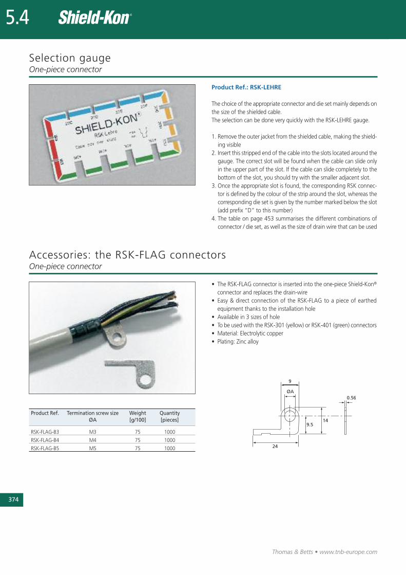
374
Thomas & Betts • www.tnb-europe.com
5.4
Selection gauge
Product Ref.: RSK-LEHRE
The choice of the appropriate connector and die set mainly depends onthe size of the shielded cable. The selection can be done very quickly with the RSK-LEHRE gauge.
1. Remove the outer jacket from the shielded cable, making the shield-ing visible
2. Insert this stripped end of the cable into the slots located around thegauge. The correct slot will be found when the cable can slide onlyin the upper part of the slot. If the cable can slide completely to thebottom of the slot, you should try with the smaller adjacent slot.
3. Once the appropriate slot is found, the corresponding RSK connec-tor is defined by the colour of the strip around the slot, whereas thecorresponding die set is given by the number marked below the slot(add prefix “D” to this number)
4. The table on page 453 summarises the different combinations ofconnector / die set, as well as the size of drain wire that can be used
One-piece connector
• The RSK-FLAG connector is inserted into the one-piece Shield-Kon®
connector and replaces the drain-wire• Easy & direct connection of the RSK-FLAG to a piece of earthed
equipment thanks to the installation hole• Available in 3 sizes of hole • To be used with the RSK-301 (yellow) or RSK-401 (green) connectors• Material: Electrolytic copper• Plating: Zinc alloy
Product Ref. Termination screw size Weight QuantityØA [g/100] [pieces]
RSK-FLAG-B3 M3 75 1000
RSK-FLAG-B4 M4 75 1000
RSK-FLAG-B5 M5 75 1000
Accessories: the RSK-FLAG connectorsOne-piece connector

Ergonomic hand tools
Product Ref.: ERG740
• Robust construction: metallic frame, partially covered with plastic• Dies are easily interchangeable (to be ordered separately)• Parallel action crimp• Shure-Stake™ mechanism: once pressing has commenced, thetool can be re-opened only after successful completion of thecrimping cycle
• Supplied in a plastic case with: 1 tool, 1 bench-mount stand foreasier use in volume production, 1 gauge (Product Ref. RSK-LEHRE)for instant selection of the die and the connector to be used
• Dimensions of tool (L x W x H): 210 x 155 x 25 mm• Weight of tool: 470 g• Dimensions of plastic case (L x W x H): 245 x 210 x 55 mm• Weight of plastic case with content: 930 g
Product Ref.: ERG740-01
• Same as ERG740, but in addition, supplied with 4 metal dies(D-101A, D-201D, D-301G, D-401K)
• Dimensions of plastic case (L x W x H): 245 x 210 x 55 mm• Weight of plastic case with content: 1200 g
Metal Dies for ERG740• For mass production and medium to high volumes• Made of hardened steel, does not wear• The Product Ref. is engraved on the upper part and on the lowerpart of the die set and the die is marked with a dot having thesame colour as the corresponding connector
• Packaging: 1 die set in a cardboard box with Euro slot• Weight: approx. 75 g• Packaging size (L x W x H): 45 x 45 x 70 mm
One-piece connector
375
Thomas & Betts • www.tnb-europe.com
5.4
Product Ref. Colour Shield diameter For connector[mm]
D-101A Red 1.27 - 1.79 RSK 101
D-101B Red 1.80 - 2.28 RSK 101
D-201C Blue 2.29 - 2.55 RSK 201
D-201D Blue 2.56 - 3.00 RSK 201
D-201E Blue 3.01 - 3.34 RSK 201
D-201F Blue 3.35 - 3.65 RSK 201
D-301G Yellow 3.66 - 4.13 RSK 301
D-301H Yellow 4.14 - 4.71 RSK 301
D-301J Yellow 4.72 - 5.12 RSK 301
D-401K Green 5.13 - 5.86 RSK 401
D-401L Green 5.87 - 6.36 RSK 401
D-401M Green 6.37 - 7.00 RSK 401
D-401N Green 7.01 - 7.62 RSK 401
ERG740 die selection chart
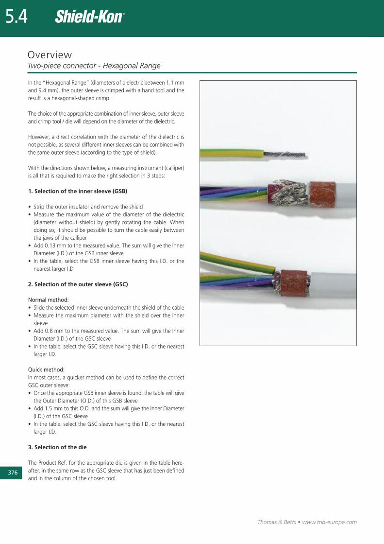
376
Thomas & Betts • www.tnb-europe.com
5.4
OverviewTwo-piece connector - Hexagonal Range
In the “Hexagonal Range” (diameters of dielectric between 1.1 mmand 9.4 mm), the outer sleeve is crimped with a hand tool and theresult is a hexagonal-shaped crimp.
The choice of the appropriate combination of inner sleeve, outer sleeveand crimp tool / die will depend on the diameter of the dielectric.
However, a direct correlation with the diameter of the dielectric isnot possible, as several different inner sleeves can be combined withthe same outer sleeve (according to the type of shield).
With the directions shown below, a measuring instrument (calliper)is all that is required to make the right selection in 3 steps:
1. Selection of the inner sleeve (GSB)
• Strip the outer insulator and remove the shield• Measure the maximum value of the diameter of the dielectric(diameter without shield) by gently rotating the cable. Whendoing so, it should be possible to turn the cable easily betweenthe jaws of the calliper
• Add 0.13 mm to the measured value. The sum will give the InnerDiameter (I.D.) of the GSB inner sleeve
• In the table, select the GSB inner sleeve having this I.D. or thenearest larger I.D
2. Selection of the outer sleeve (GSC)
Normal method:• Slide the selected inner sleeve underneath the shield of the cable• Measure the maximum diameter with the shield over the innersleeve
• Add 0.8 mm to the measured value. The sum will give the InnerDiameter (I.D.) of the GSC sleeve
• In the table, select the GSC sleeve having this I.D. or the nearestlarger I.D.
Quick method:In most cases, a quicker method can be used to define the correctGSC outer sleeve:• Once the appropriate GSB inner sleeve is found, the table will givethe Outer Diameter (O.D.) of this GSB sleeve
• Add 1.5 mm to this O.D. and the sum will give the Inner Diameter(I.D.) of the GSC sleeve
• In the table, select the GSC sleeve having this I.D. or the nearestlarger I.D.
3. Selection of the die
The Product Ref. for the appropriate die is given in the table here-after, in the same row as the GSC sleeve that has just been definedand in the column of the chosen tool.
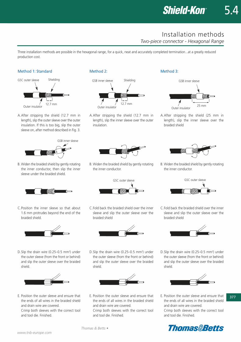
Installation methodsTwo-piece connector - Hexagonal Range
377
Thomas & Betts •www.tnb-europe.com
5.4
Method 1: Standard
A.After stripping the shield (12.7 mm inlength), slip the outer sleeve over the outerinsulation. If this is too big, slip the outersleeve on, after method described in Fig. 3.
B.Widen the braided shield by gently rotatingthe inner conductor, then slip the innersleeve under the braided shield.
C.Position the inner sleeve so that about1.6 mm protrudes beyond the end of thebraided shield.
D.Slip the drain wire (0.25–0.5 mm2) underthe outer sleeve (from the front or behind)and slip the outer sleeve over the braidedshield.
E. Position the outer sleeve and ensure thatthe ends of all wires in the braided shieldand drain wire are covered.Crimp both sleeves with the correct tooland tool die. Finished.
Method 2:
A.After stripping the shield (12.7 mm inlength), slip the inner sleeve over the outerinsulation.
B.Widen the braided shield by gently rotatingthe inner conductor.
C.Fold back the braided shield over the innersleeve and slip the outer sleeve over thebraided shield
D.Slip the drain wire (0.25–0.5 mm2) underthe outer sleeve (from the front or behind)and slip the outer sleeve over the braidedshield.
E. Position the outer sleeve and ensure thatthe ends of all wires in the braided shieldand drain wire are covered.Crimp both sleeves with the correct tooland tool die. Finished.
Method 3:
A.After stripping the shield (25 mm inlength), slip the inner sleeve over thebraided shield
B.Widen the braided shield by gently rotatingthe inner conductor.
C.Fold back the braided shield over the innersleeve and slip the outer sleeve over thebraided shield
D.Slip the drain wire (0.25–0.5 mm2) underthe outer sleeve (from the front or behind)and slip the outer sleeve over the braidedshield.
E. Position the outer sleeve and ensure thatthe ends of all wires in the braided shieldand drain wire are covered.Crimp both sleeves with the correct tooland tool die. Finished.
Three installation methods are possible in the hexagonal range, for a quick, neat and accurately completed termination...at a greatly reduced production cost.
GSC outer sleeve Shielding
Outer insulator
GSB inner sleeve Shielding
Outer insulator
GSB inner sleeve
Outer insulator
GSB inner sleeve
GSC outer sleeve GSC outer sleeve
12.7 mm 25 mm12.7 mm
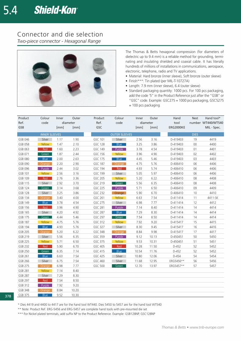
378
Thomas & Betts • www.tnb-europe.com
5.4
Connector and die selection
The Thomas & Betts hexagonal compression (for diameters ofdielectric up to 9.4 mm) is a reliable method for grounding, termi-nating and insulating shielded and coaxial cable. It has literallyhundreds of millions of installations in communications, aerospace,electronic, telephone, radio and TV applications.• Material: Hard bronze (inner sleeve), Soft bronze (outer sleeve)• Finish***: Tin plated (per MIL-T-10727A)• Length: 7.9 mm (inner sleeve), 6.4 (outer sleeve)• Standard packaging quantity: 1000 pcs. For 100 pcs packaging,add the code ‘5” in the Product Reference just after the “GSB” or“GSC” code. Example: GSC275 = 1000 pcs packaging, GSC5275= 100 pcs packaging
Two-piece connector - Hexagonal Range
Product Colour Inner Outer Product Colour Inner Outer Hand Nest Hand tool*Ref. code diameter Ref. code diameter tool number WT440/WT540GSB [mm] [mm] GSC [mm] [mm] ERG2000KE MIL - Spec.
INNER SLEEVES OUTER SLEEVES DIES
GSB 046 Silver 1.17 1.90 GSC 101 Silver 2.56 3.16 D-419403 19 4419
GSB 058 Yellow 1.47 2.10 GSC 128 Blue 3.25 3.86 D-419403 00 4400
GSB 063 Red 1.60 2.23 GSC 149 Purple 3.78 4.54 D-419403 01 4401
GSB 071 Green 1.87 2.44 GSC 156 Yellow 3.96 4.90 D-419403 02 4402
GSB 080 Blue 2.00 2.63 GSC 175 Blue 4.45 5.46 D-419403 03 4403
GSB 090 Orange 2.20 2.90 GSC 187 Orange 4.75 5.76 D-406410 06 4406
GSB 096 Purple 2.44 3.02 GSC 194 Red 4.93 5.74 D-406410 06 4406
GSB 101 Yellow 2.56 3.16 GSC 199 Silver 5.05 5.97 D-406410 06 4406
GSB 109 Red 2.76 3.36 GSC 205 Yellow 5.20 6.22 D-406410 08 4408
GSB 115 Silver 2.92 3.70 GSC 219 Green 5.56 6.35 D-406410 08 4408
GSB 124 Green 3.14 3.68 GSC 225 Purple 5.71 6.50 D-406410 09 4409
GSB 128 Silver 3.25 3.86 GSC 232 Orange 5.90 6.70 D-406410 10 4410
GSB 134 Orange 3.40 4.00 GSC 261 Yellow 6.63 7.54 D-411414 11 4411-SK
GSB 149 Blue 3.78 4.54 GSC 275 Silver 6.98 7.77 D-411414 12 4412
GSB 156 Red 3.96 4.90 GSC 281 Purple 7.14 8.40 D-411414 14 4414
GSB 165 Silver 4.20 4.92 GSC 287 Blue 7.29 8.30 D-411414 14 4414
GSB 175 Green 4.44 5.46 GSC 297 Green 7.54 8.50 D-411414 14 4414
GSB 187 Yellow 4.75 5.76 GSC 312 Yellow 7.92 9.20 D-415417 15 4415
GSB 194 Blue 4.93 5.76 GSC 327 Silver 8.30 9.45 D-415417 16 4416
GSB 205 Orange 5.20 6.22 GSC 348 Orange 8.84 9.98 D-415417 17 4417
GSB 219 Silver 5.56 6.35 GSC 359 Purple 9.12 10.13 D-450451 50 5450
GSB 225 Yellow 5.71 6.50 GSC 375 Yellow 9.53 10.31 D-450451 51 5451
GSB 232 Red 5.90 6.70 GSC 405 Red 10.28 11.50 D-452 52 5452
GSB 250 Green 6.35 7.14 GSC 415 Blue 10.54 11.76 D-452 52 5452
GSB 261 Blue 6.63 7.54 GSC 425 Silver 10.80 12.06 D-454 54 5454
GSB 266 Silver 6.75 7.54 GSC 460 Silver 11.68 12.95 ERG5456** 56 5456
GSB 275 Orange 6.98 7.77 GSC 500 Green 12.70 13.97 ERG5457** 57 5457
GSB 281 Yellow 7.14 8.40
GSB 287 Silver 7.29 8.30
GSB 297 Red 7.54 8.50
GSB 312 Purple 7.92 9.20
GSB 348 Orange 8.84 10.20
GSB 375 Blue 9.52 10.30
* Dies 4419 and 4400 to 4417 are for the hand tool WT440. Dies 5450 to 5457 are for the hand tool WT540
** Note: Product Ref. ERG-5456 and ERG-5457 are complete hand tools with pre-mounted die set
*** For Nickel plated terminals, add suffix NP to the Product Reference. Example: GSB128NP, GSC128NP
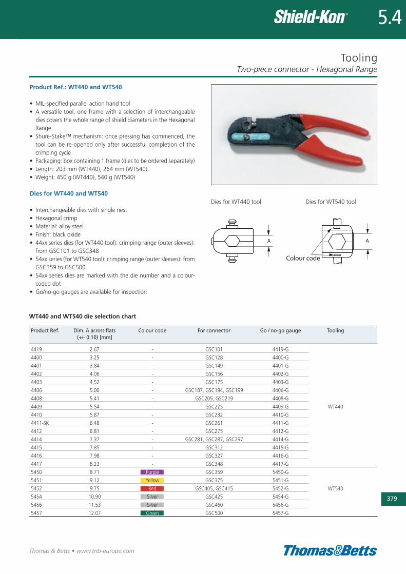
Tooling
Product Ref.: WT440 and WT540
• MIL-specified parallel action hand tool• A versatile tool, one frame with a selection of interchangeabledies covers the whole range of shield diameters in the HexagonalRange
• Shure-Stake™ mechanism: once pressing has commenced, thetool can be re-opened only after successful completion of thecrimping cycle
• Packaging: box containing 1 frame (dies to be ordered separately)• Length: 203 mm (WT440), 264 mm (WT540)• Weight: 450 g (WT440), 540 g (WT540)
Dies for WT440 and WT540
• Interchangeable dies with single nest• Hexagonal crimp• Material: alloy steel• Finish: black oxide• 44xx series dies (for WT440 tool): crimping range (outer sleeves):from GSC101 to GSC348
• 54xx series (for WT540 tool): crimping range (outer sleeves): fromGSC359 to GSC500
• 54xx series dies are marked with the die number and a colour-coded dot
• Go/no-go gauges are available for inspection
Two-piece connector - Hexagonal Range
379
Thomas & Betts • www.tnb-europe.com
5.4
Dies for WT440 tool
Product Ref. Dim. A across flats Colour code For connector Go / no-go gauge Tooling(+/- 0.10) [mm]
4419 2.67 - GSC101 4419-G
4400 3.25 - GSC128 4400-G
4401 3.84 - GSC149 4401-G
4402 4.06 - GSC156 4402-G
4403 4.52 - GSC175 4403-G
4406 5.00 - GSC187, GSC194, GSC199 4406-G
4408 5.41 - GSC205, GSC219 4408-G
4409 5.54 - GSC225 4409-G WT440
4410 5.87 - GSC232 4410-G
4411-SK 6.48 - GSC261 4411-G
4412 6.81 - GSC275 4412-G
4414 7.37 - GSC281, GSC287, GSC297 4414-G
4415 7.85 - GSC312 4415-G
4416 7.98 - GSC327 4416-G
4417 8.23 - GSC348 4417-G
5450 8.71 Purple GSC359 5450-G
5451 9.12 Yellow GSC375 5451-G
5452 9.75 Red GSC405, GSC415 5452-G WT540
5454 10.90 Silver GSC425 5454-G
5456 11.53 Silver GSC460 5456-G
5457 12.07 Green GSC500 5457-G
Dies for WT540 tool
WT440 and WT540 die selection chart
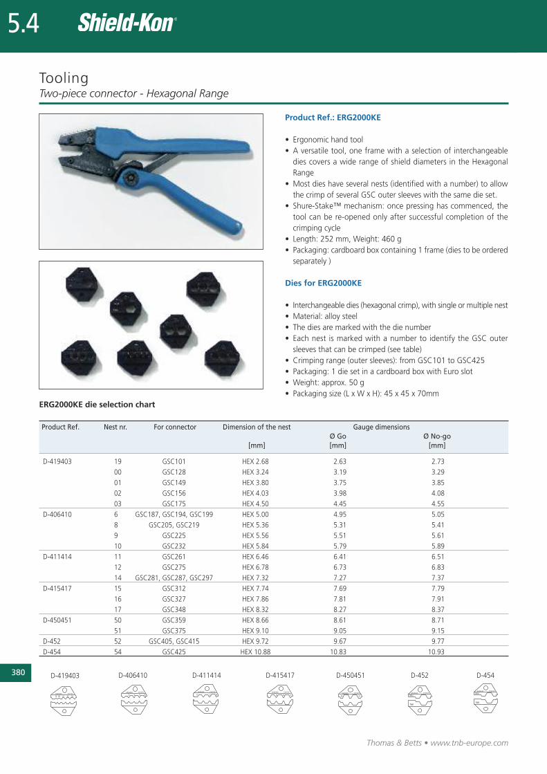
380
Thomas & Betts • www.tnb-europe.com
5.4
Tooling
Product Ref.: ERG2000KE
• Ergonomic hand tool• A versatile tool, one frame with a selection of interchangeabledies covers a wide range of shield diameters in the HexagonalRange
• Most dies have several nests (identified with a number) to allowthe crimp of several GSC outer sleeves with the same die set.
• Shure-Stake™ mechanism: once pressing has commenced, thetool can be re-opened only after successful completion of thecrimping cycle
• Length: 252 mm, Weight: 460 g• Packaging: cardboard box containing 1 frame (dies to be orderedseparately )
Dies for ERG2000KE
• Interchangeable dies (hexagonal crimp), with single or multiple nest• Material: alloy steel• The dies are marked with the die number• Each nest is marked with a number to identify the GSC outersleeves that can be crimped (see table)
• Crimping range (outer sleeves): from GSC101 to GSC425• Packaging: 1 die set in a cardboard box with Euro slot• Weight: approx. 50 g• Packaging size (L x W x H): 45 x 45 x 70mm
Two-piece connector - Hexagonal Range
Product Ref. Nest nr. For connector Dimension of the nest Gauge dimensionsØ Go Ø No-go
[mm] [mm] [mm]
D-419403 19 GSC101 HEX 2.68 2.63 2.73
00 GSC128 HEX 3.24 3.19 3.29
01 GSC149 HEX 3.80 3.75 3.85
02 GSC156 HEX 4.03 3.98 4.08
03 GSC175 HEX 4.50 4.45 4.55
D-406410 6 GSC187, GSC194, GSC199 HEX 5.00 4.95 5.05
8 GSC205, GSC219 HEX 5.36 5.31 5.41
9 GSC225 HEX 5.56 5.51 5.61
10 GSC232 HEX 5.84 5.79 5.89
D-411414 11 GSC261 HEX 6.46 6.41 6.51
12 GSC275 HEX 6.78 6.73 6.83
14 GSC281, GSC287, GSC297 HEX 7.32 7.27 7.37
D-415417 15 GSC312 HEX 7.74 7.69 7.79
16 GSC327 HEX 7.86 7.81 7.91
17 GSC348 HEX 8.32 8.27 8.37
D-450451 50 GSC359 HEX 8.66 8.61 8.71
51 GSC375 HEX 9.10 9.05 9.15
D-452 52 GSC405, GSC415 HEX 9.72 9.67 9.77
D-454 54 GSC425 HEX 10.88 10.83 10.93
D-419403 D-406410 D-411414 D-415417 D-450451 D-452 D-454
ERG2000KE die selection chart
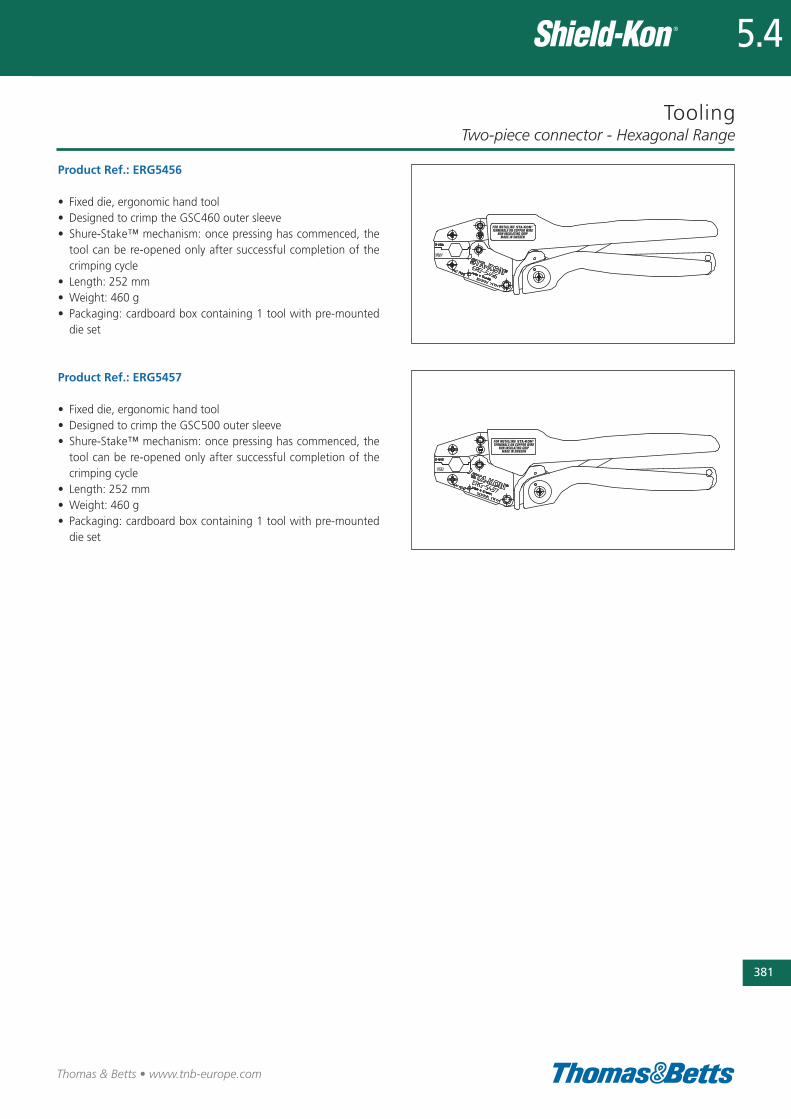
Tooling
Product Ref.: ERG5456
• Fixed die, ergonomic hand tool• Designed to crimp the GSC460 outer sleeve• Shure-Stake™ mechanism: once pressing has commenced, thetool can be re-opened only after successful completion of thecrimping cycle
• Length: 252 mm• Weight: 460 g• Packaging: cardboard box containing 1 tool with pre-mounteddie set
Product Ref.: ERG5457
• Fixed die, ergonomic hand tool• Designed to crimp the GSC500 outer sleeve• Shure-Stake™ mechanism: once pressing has commenced, thetool can be re-opened only after successful completion of thecrimping cycle
• Length: 252 mm• Weight: 460 g• Packaging: cardboard box containing 1 tool with pre-mounteddie set
Two-piece connector - Hexagonal Range
381
Thomas & Betts • www.tnb-europe.com
5.4
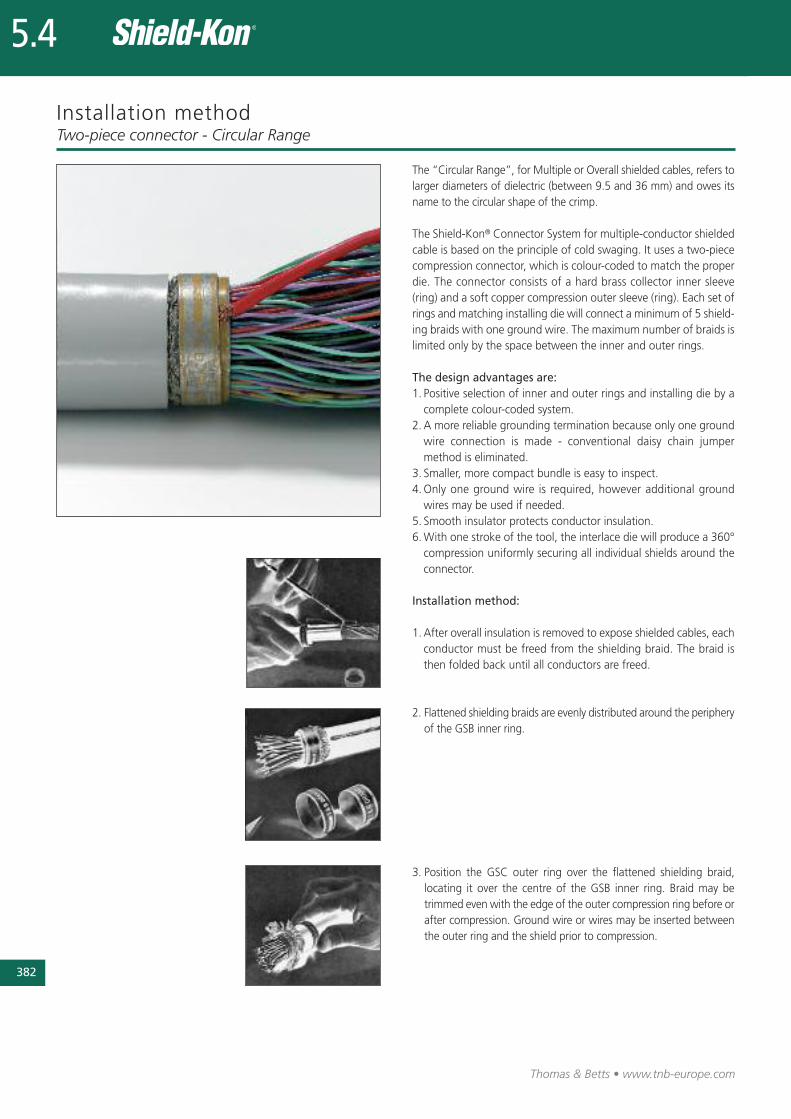
382
Thomas & Betts • www.tnb-europe.com
5.4
Installation method
The “Circular Range”, for Multiple or Overall shielded cables, refers tolarger diameters of dielectric (between 9.5 and 36 mm) and owes itsname to the circular shape of the crimp.
The Shield-Kon® Connector System for multiple-conductor shieldedcable is based on the principle of cold swaging. It uses a two-piececompression connector, which is colour-coded to match the properdie. The connector consists of a hard brass collector inner sleeve(ring) and a soft copper compression outer sleeve (ring). Each set ofrings and matching installing die will connect a minimum of 5 shield-ing braids with one ground wire. The maximum number of braids islimited only by the space between the inner and outer rings.
The design advantages are:1. Positive selection of inner and outer rings and installing die by acomplete colour-coded system.
2. A more reliable grounding termination because only one groundwire connection is made - conventional daisy chain jumpermethod is eliminated.
3. Smaller, more compact bundle is easy to inspect.4.Only one ground wire is required, however additional groundwires may be used if needed.
5. Smooth insulator protects conductor insulation. 6.With one stroke of the tool, the interlace die will produce a 360°compression uniformly securing all individual shields around theconnector.
Installation method:
1.After overall insulation is removed to expose shielded cables, eachconductor must be freed from the shielding braid. The braid isthen folded back until all conductors are freed.
2. Flattened shielding braids are evenly distributed around the peripheryof the GSB inner ring.
3. Position the GSC outer ring over the flattened shielding braid,locating it over the centre of the GSB inner ring. Braid may betrimmed even with the edge of the outer compression ring before orafter compression. Ground wire or wires may be inserted betweenthe outer ring and the shield prior to compression.
Two-piece connector - Circular Range
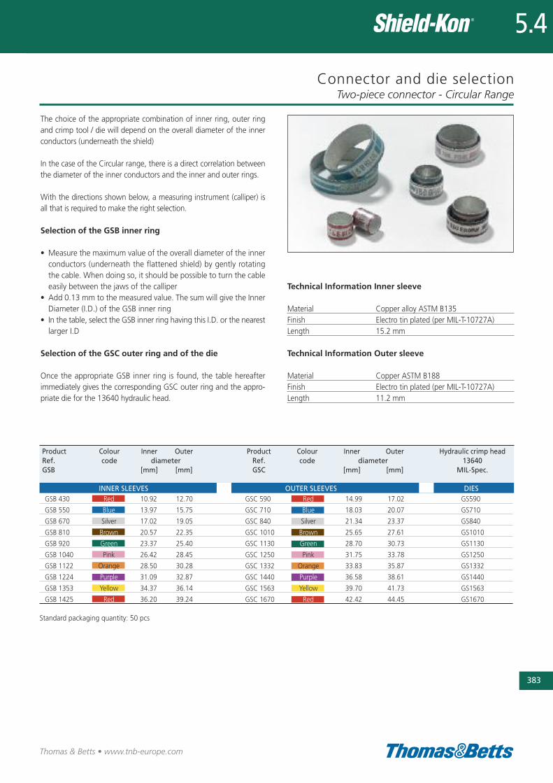
Connector and die selection
The choice of the appropriate combination of inner ring, outer ringand crimp tool / die will depend on the overall diameter of the innerconductors (underneath the shield)
In the case of the Circular range, there is a direct correlation betweenthe diameter of the inner conductors and the inner and outer rings.
With the directions shown below, a measuring instrument (calliper) isall that is required to make the right selection.
Selection of the GSB inner ring
• Measure the maximum value of the overall diameter of the innerconductors (underneath the flattened shield) by gently rotatingthe cable. When doing so, it should be possible to turn the cableeasily between the jaws of the calliper
• Add 0.13 mm to the measured value. The sum will give the InnerDiameter (I.D.) of the GSB inner ring
• In the table, select the GSB inner ring having this I.D. or the nearestlarger I.D
Selection of the GSC outer ring and of the die
Once the appropriate GSB inner ring is found, the table hereafterimmediately gives the corresponding GSC outer ring and the appro-priate die for the 13640 hydraulic head.
Two-piece connector - Circular Range
383
Thomas & Betts • www.tnb-europe.com
5.4
Product Colour Inner Outer Product Colour Inner Outer Hydraulic crimp headRef. code diameter Ref. code diameter 13640GSB [mm] [mm] GSC [mm] [mm] MIL-Spec.
INNER SLEEVES OUTER SLEEVES DIESGSB 430 Red 10.92 12.70 GSC 590 Red 14.99 17.02 GS590
GSB 550 Blue 13.97 15.75 GSC 710 Blue 18.03 20.07 GS710
GSB 670 Silver 17.02 19.05 GSC 840 Silver 21.34 23.37 GS840
GSB 810 Brown 20.57 22.35 GSC 1010 Brown 25.65 27.61 GS1010
GSB 920 Green 23.37 25.40 GSC 1130 Green 28.70 30.73 GS1130
GSB 1040 Pink 26.42 28.45 GSC 1250 Pink 31.75 33.78 GS1250
GSB 1122 Orange 28.50 30.28 GSC 1332 Orange 33.83 35.87 GS1332
GSB 1224 Purple 31.09 32.87 GSC 1440 Purple 36.58 38.61 GS1440
GSB 1353 Yellow 34.37 36.14 GSC 1563 Yellow 39.70 41.73 GS1563
GSB 1425 Red 36.20 39.24 GSC 1670 Red 42.42 44.45 GS1670
Standard packaging quantity: 50 pcs
Technical Information Inner sleeve
Material Copper alloy ASTM B135Finish Electro tin plated (per MIL-T-10727A)Length 15.2 mm
Technical Information Outer sleeve
Material Copper ASTM B188Finish Electro tin plated (per MIL-T-10727A)Length 11.2 mm
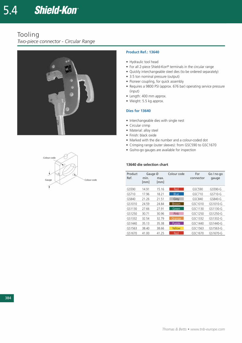
384
Thomas & Betts • www.tnb-europe.com
5.4
Tooling
Product Ref.: 13640
• Hydraulic tool head• For all 2-piece Shield-Kon® terminals in the circular range• Quickly interchangeable steel dies (to be ordered separately)• 3.5 ton nominal pressure (output)• Pioneer coupling, for quick assembly• Requires a 9800 PSI (approx. 676 bar) operating service pressure(input)
• Length: 400 mm approx.• Weight: 5.5 kg approx.
Dies for 13640
• Interchangeable dies with single nest• Circular crimp• Material: alloy steel• Finish: black oxide• Marked with the die number and a colour-coded dot• Crimping range (outer sleeves): from GSC590 to GSC1670• Go/no-go gauges are available for inspection
13640 die selection chart
Two-piece connector - Circular Range
Product Gauge Ø Colour code For Go / no-goRef. min. max. connector gauge
[mm] [mm]
GS590 14.91 15.16 Red GSC590 GS590-G
GS710 17.96 18.21 Blue GSC710 GS710-G
GS840 21.26 21.51 Grey GSC840 GS840-G
GS1010 24.59 24.84 Brown GSC1010 GS1010-G
GS1130 27.66 27.91 Green GSC1130 GS1130-G
GS1250 30.71 30.96 Pink GSC1250 GS1250-G
GS1332 32.54 32.79 Orange GSC1332 GS1332-G
GS1440 35.13 35.38 Purple GSC1440 GS1440-G
GS1563 38.40 38.66 Yellow GSC1563 GS1563-G
GS1670 41.00 41.25 Red GSC1670 GS1670-G
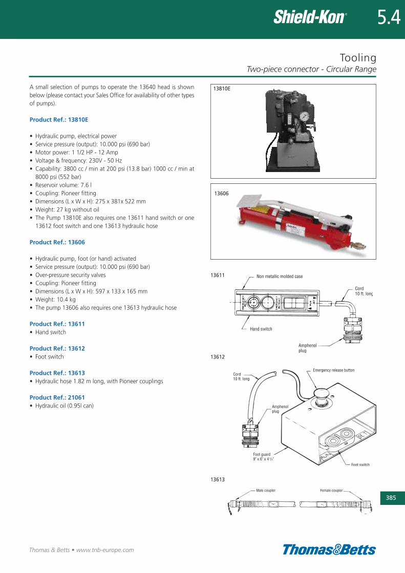
Tooling
A small selection of pumps to operate the 13640 head is shownbelow (please contact your Sales Office for availability of other typesof pumps).
Product Ref.: 13810E
• Hydraulic pump, electrical power• Service pressure (output): 10.000 psi (690 bar)• Motor power: 1 1/2 HP - 12 Amp• Voltage & frequency: 230V - 50 Hz• Capability: 3800 cc / min at 200 psi (13.8 bar) 1000 cc / min at8000 psi (552 bar)
• Reservoir volume: 7.6 l• Coupling: Pioneer fitting• Dimensions (L x W x H): 275 x 381x 522 mm• Weight: 27 kg without oil• The Pump 13810E also requires one 13611 hand switch or one13612 foot switch and one 13613 hydraulic hose
Product Ref.: 13606
• Hydraulic pump, foot (or hand) activated• Service pressure (output): 10.000 psi (690 bar)• Over-pressure security valves• Coupling: Pioneer fitting• Dimensions (L x W x H): 597 x 133 x 165 mm• Weight: 10.4 kg• The pump 13606 also requires one 13613 hydraulic hose
Product Ref.: 13611• Hand switch
Product Ref.: 13612• Foot switch
Product Ref.: 13613• Hydraulic hose 1.82 m long, with Pioneer couplings
Product Ref.: 21061• Hydraulic oil (0.95l can)
Two-piece connector - Circular Range
385
Thomas & Betts • www.tnb-europe.com
5.4
13611
13613
13612
13606
13810E