st80/st80l f fieldbus - fluid components international · 2019-04-11 · st80/st80l foundation™...
TRANSCRIPT
ST80/ST80L Foundation™ Fieldbus
ii Fluid Components International LLC
Notice of Proprietary RightsThis document contains confidential technical data, including trade secrets and proprietary information which is the property of Fluid Components International LLC (FCI). Disclosure of this data to you is expressly conditioned upon your assent that its use is limited to use within your company only (and does not include manufacture or processing uses). Any other use is strictly prohibited without the prior written consent of FCI.
© Copyright 2019 by Fluid Components International LLC. All rights reserved. FCI is a registered trademark of Fluid Components International LLC. Information subject to change without notice.
ST80/ST80L Foundation™ Fieldbus 06EN003492 Rev. A
Fluid Components International LLC iii
Table of Contents
Introduction .................................................................................................................................................................................................................................................1
General ....................................................................................................................................................................................................................................................1
Definition .................................................................................................................................................................................................................................................1
Installation ..................................................................................................................................................................................................................................................2
General ...................................................................................................................................................................................................................................................2
Electrical Wiring ......................................................................................................................................................................................................................................2
Topology and Network Configuration......................................................................................................................................................................................................3
General Operation .......................................................................................................................................................................................................................................3
Functional Description ............................................................................................................................................................................................................................3
Function Transducer Blocks .....................................................................................................................................................................................................................3
Data Types Definitions ............................................................................................................................................................................................................................3
Resource Block ........................................................................................................................................................................................................................................5
Resource Block ........................................................................................................................................................................................................................................6
Process Data Transducer Block ...............................................................................................................................................................................................................7
Process Data Transducer Block Parameter List.......................................................................................................................................................................................8
Service Transducer Block ........................................................................................................................................................................................................................9
Factory Calibration Limits (Configuration Software Factory/Factory Parameters) .................................................................................................................................9
Process Engineering Units (Configuration Software Basic Setup/Units & Basic Setup/Pipe Size) .......................................................................................................9
Factory Restore Command (Configuration Software Basic Setup/Groups) ..........................................................................................................................................10
Individual Sensors Data View ...............................................................................................................................................................................................................10
Service Transducer Block Parameter List ..............................................................................................................................................................................................10
Flow Analog Input Block .......................................................................................................................................................................................................................12
Flow Analog Input Block Parameter List ...............................................................................................................................................................................................13
Temperature Analog Input Block ...........................................................................................................................................................................................................14
Temperature Analog Input Block Parameter List ..................................................................................................................................................................................14
Totalizer Analog Input Block ..................................................................................................................................................................................................................15
Totalizer Analog Input Block Parameter List .........................................................................................................................................................................................15
Pressure Analog Input Block (not applicable to ST80/ST80L) ..............................................................................................................................................................16
PID Block ...............................................................................................................................................................................................................................................17
PID Block Parameter List .......................................................................................................................................................................................................................17
Link Master Function ................................................................................................................................................................................................................................18
Operation ...............................................................................................................................................................................................................................................18
Configuring Foundation Fieldbus ................................................................................................................................................................................................................19
Setting the ST80/ST80L for Foundation Fieldbus Operation ..................................................................................................................................................................19
Configuring the Foundation Fieldbus AI Blocks ......................................................................................................................................................................................19
Configuring Flow Analog Input Block (AI) .............................................................................................................................................................................................19
Configuring Temperature AI Block.........................................................................................................................................................................................................21
Configuring Totalizer AI Block ...............................................................................................................................................................................................................21
Using the Foundation Fieldbus Service Transducer Block ..........................................................................................................................................................................22
Service Transducer Block, Introduction .................................................................................................................................................................................................22
Advanced Instrument Functions (Not Applicable to ST80/ST80L) .......................................................................................................................................................23
Device Description Files ...........................................................................................................................................................................................................................23
General DD FILES ..................................................................................................................................................................................................................................23
Emerson 475 Field Communicator ........................................................................................................................................................................................................24
Technical Characteristics ..........................................................................................................................................................................................................................25
Customer Service/Technical Support .......................................................................................................................................................................................................27
Appendix A - ST100 Product Family Foundation Fieldbus Engineering Units/Codes ................................................................................................................................29
06EN003492 Rev. A ST80/ST80L Foundation™ Fieldbus
iv Fluid Components International LLC
INTENTIONALLY LEFT BLANK
ST80/ST80L Foundation™ Fieldbus
Fluid Components International LLC 1
Introduction
General
This manual describes the ST100 family products’ (of which ST80/ST80L is a member) Foundation™ Fieldbus features, its operation, and con-figuration. The ST100 can provide up to four different process variables. It provides Flow, Temperature, Flow Totalizer, and Pressure (the latter not applicable to ST80/ST80L) as outputs. The flow output can be selected as volumetric, mass or velocity units. There is built-in support for multi-sensor input, but that feature does not apply to ST80/S80L.
Foundation Fieldbus is different from other communication protocols because it is designed to resolve process control applications instead of just transfer data in a digital mode.
The software description in this document is applicable to all members of the ST100 family product line configured with Foundation Fieldbus digital communication protocol. Any difference with the ST80/ST80L is noted.
Foundation Fieldbus operation is provided through an optional add-on card that plugs into the ST80/ST80L main board.
Definition
AI Block: Analog Input Block. This block receives the ST100 family product process data variables from the Process Data Transducer Block and makes the process data available for the function blocks.
There are four AI blocks in the ST100 product family. These are the Flow AI Block, Temperature AI Block, Totalizer AI Block, and the Pressure AI block (the latter not applicable to the ST80/ST80L).
TB Block: Transducer Block. This block makes the connection to the ST100 family product signal processing hardware, presents the process variables and eases instrument setup through Foundation Fieldbus.
PID Block: The Proportional, Integral, Derivative, control function block offers a lot of control algorithms that use the Proportional, Integral, and Derivative Terms. The algorithm of the ST100 family product PID is the non-iterative, ISA version.
RS Block: The Resource block contains basic Foundation Fieldbus information about the ST100 family product and some configuration data.
FF Configurator: A software tool used to access data and configure Foundation Fieldbus devices.
DD Files: The Device Description Files are used by configuration software, like the NI configurator or handheld configurators like the Emerson 475, or other Foundation Fieldbus hosts. The DD files describe the Foundation Fieldbus device. They also allow for custom manufacturer-specific features to be added to a Foundation Fieldbus device, and provide the means for the host to access the instrument’s custom features.
FCI Configurator: A Windows-based PC application for accessing ST80/ST80L functions and features. The application is typically used for basic instrument setup and configuration, as well as provide access to advanced functions. The FCI configurator/host PC communicates to the instrument through the instrument’s USB service port.
ST80/ST80L Foundation™ Fieldbus
2 Fluid Components International LLC
Installation
General
For details on installation and installation options refer to the ST80/ST80L main manual 06EN003490.
Electrical Wiring
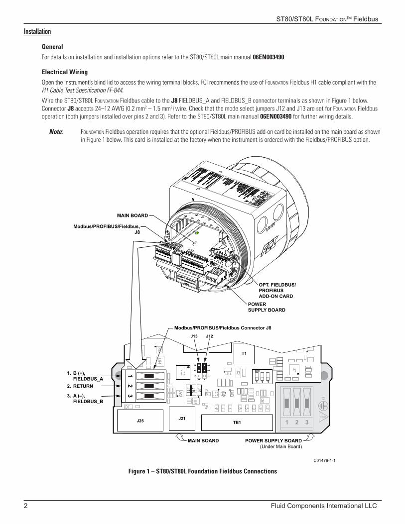
Open the instrument’s blind lid to access the wiring terminal blocks. FCI recommends the use of Foundation Fieldbus H1 cable compliant with the H1 Cable Test Specification FF-844.
Wire the ST80/ST80L Foundation Fieldbus cable to the J8 FIELDBUS_A and FIELDBUS_B connector terminals as shown in Figure 1 below. Connector J8 accepts 24–12 AWG (0.2 mm2 – 1.5 mm2) wire. Check that the mode select jumpers J12 and J13 are set for Foundation Fieldbus operation (both jumpers installed over pins 2 and 3). Refer to the ST80/ST80L main manual 06EN003490 for further wiring details.
Note: Foundation Fieldbus operation requires that the optional Fieldbus/PROFIBUS add-on card be installed on the main board as shown in Figure 1 below. This card is installed at the factory when the instrument is ordered with the Fieldbus/PROFIBUS option.
Figure 1 – ST80/ST80L Foundation Fieldbus Connections
C01479-1-1
J9
12
3
12
3
12
3
J12J13
J10J11
T1
1.
2.
3.
B (+),FIELDBUS_ARETURN
A (–),FIELDBUS_B
J25 J21TB1 1 2 3
Modbus/PROFIBUS/Fieldbus,J8
MAIN BOARD
OPT. FIELDBUS/PROFIBUSADD-ON CARD
POWER SUPPLY BOARD
MAIN BOARD
Modbus/PROFIBUS/Fieldbus Connector J8
POWER SUPPLY BOARD(Under Main Board)
ST80/ST80L Foundation™ Fieldbus
Fluid Components International LLC 3
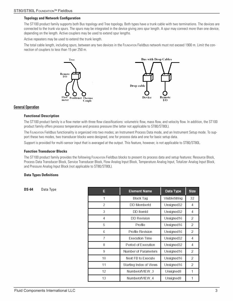
Topology and Network Configuration
The ST100 product family supports both Bus topology and Tree topology. Both types have a trunk cable with two terminations. The devices are connected to the trunk via spurs. The spurs may be integrated in the device giving zero spur length. A spur may connect more than one device, depending on the length. Active couplers may be used to extend spur lengths.
Active repeaters may be used to extend the trunk length.
The total cable length, including spurs, between any two devices in the Foundation Fieldbus network must not exceed 1900 m. Limit the con-nection of couplers to less than 15 per 250 m.
General Operation
Functional Description
The ST100 product family is a flow meter with three flow classifications: volumetric flow, mass flow, and velocity flow. In addition, the ST100 product family offers process temperature and process pressure (the latter not applicable to ST80/ST80L).
The Foundation Fieldbus functionality is organized into two modes; an Instrument Process Data mode, and an Instrument Setup mode. To sup-port these two modes, two transducer blocks were designed, one for process data and one for basic setup data.
Support is provided for multi-sensor input that is averaged at the output. This feature, however, is not applicable to ST80/ST80L.
Function Transducer Blocks
The ST100 product family provides the following Foundation Fieldbus blocks to present its process data and setup features: Resource Block, Process Data Transducer Block, Service Transducer Block, Flow Analog Input Block, Temperature Analog Input, Totalizer Analog Input Block, and Pressure Analog Input Block (not applicable to ST80/ST80L).
Data Types Definitions
DS-64 Data Type
ST80/ST80L Foundation™ Fieldbus
4 Fluid Components International LLC
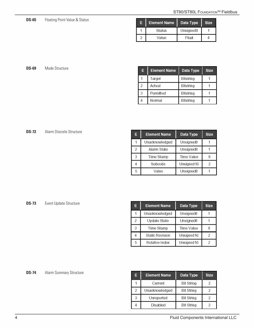
DS-65 Floating Point Value & Status
DS-74 Alarm Summary Structure
DS-73 Event Update Structure
DS-72 Alarm Discrete Structure
DS-69 Mode Structure
ST80/ST80L Foundation™ Fieldbus
Fluid Components International LLC 5
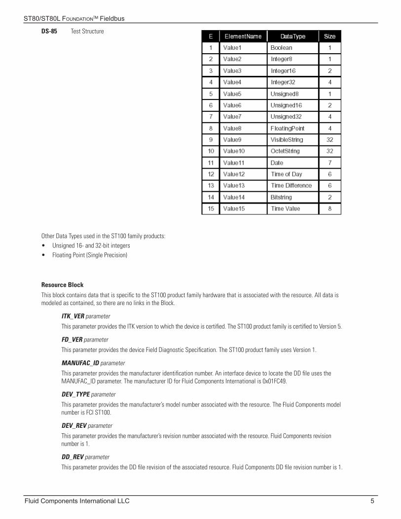
DS-85 Test Structure
Other Data Types used in the ST100 family products:• Unsigned 16- and 32-bit integers• Floating Point (Single Precision)
Resource Block
This block contains data that is specific to the ST100 product family hardware that is associated with the resource. All data is modeled as contained, so there are no links in the Block.
ITK_VER parameter
This parameter provides the ITK version to which the device is certified. The ST100 product family is certified to Version 5.
FD_VER parameter
This parameter provides the device Field Diagnostic Specification. The ST100 product family uses Version 1.
MANUFAC_ID parameter
This parameter provides the manufacturer identification number. An interface device to locate the DD file uses the MANUFAC_ID parameter. The manufacturer ID for Fluid Components International is 0x01FC49.
DEV_TYPE parameter
This parameter provides the manufacturer’s model number associated with the resource. The Fluid Components model number is FCI ST100.
DEV_REV parameter
This parameter provides the manufacturer’s revision number associated with the resource. Fluid Components revision number is 1.
DD_REV parameter
This parameter provides the DD file revision of the associated resource. Fluid Components DD file revision number is 1.
ST80/ST80L Foundation™ Fieldbus
6 Fluid Components International LLC
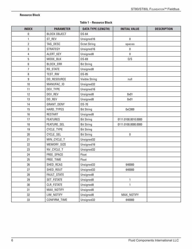
Resource Block
Table 1 – Resource Block
INDEX PARAMETER DATA TYPE (LENGTH) INITIAL VALUE DESCRIPTION
0 BLOCK OBJECT DS-64
1 ST_REV Unsigned16 0
2 TAG_DESC Octet String spaces
3 STRATEGY Unsigned16 0
4 ALERT_KEY Unsigned8 0
5 MODE_BLK DS-69 O/S
6 BLOCK_ERR Bit String
7 RS_STATE Unsigned8
8 TEST_RW DS-85
9 DD_RESOURCE Visible String null
10 MANUFAC_ID Unsigned32
11 DEV_TYPE Unsigned16
12 DEV_REV Unsigned8 0x01
13 DD_REV Unsigned8 0x01
14 GRANT_DENY DS-70
15 HARD_TYPES Bit String 0xC000
16 RESTART Unsigned8
17 FEATURES Bit String 0111.0100.0010.0000
18 FEATURE_SEL Bit String 0111.0100.0000.0000
19 CYCLE_TYPE Bit String
20 CYCLE_SEL Bit String 0
21 MIN_CYCLE_T Unsigned32
22 MEMORY_SIZE Unsigned16
23 NV_CYCLE_T Unsigned32
24 FREE_SPACE Float
25 FREE_TIME Float
26 SHED_RCAS Unsigned32 640000
27 SHED_ROUT Unsigned32 640000
28 FAULT_STATE Unsigned8
29 SET_FSTATE Unsigned8 1
30 CLR_FSTATE Unsigned8 1
31 MAX_NOTIFY Unsigned8
32 LIM_NOTIFY Unsigned8 MAX_NOTIFY
33 CONFIRM_TIME Unsigned32 640000
ST80/ST80L Foundation™ Fieldbus
Fluid Components International LLC 7
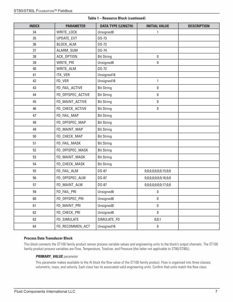
Table 1 – Resource Block (continued)
INDEX PARAMETER DATA TYPE (LENGTH) INITIAL VALUE DESCRIPTION
34 WRITE_LOCK Unsigned8 1
35 UPDATE_EVT DS-73
36 BLOCK_ALM DS-72
37 ALARM_SUM DS-74
38 ACK_OPTION Bit String 0
39 WRITE_PRI Unsigned8 0
40 WRITE_ALM DS-72
41 ITK_VER Unsigned16
42 FD_VER Unsigned16 1
43 FD_FAIL_ACTIVE Bit String 0
44 FD_OFFSPEC_ACTIVE Bit String 0
45 FD_MAINT_ACTIVE Bit String 0
46 FD_CHECK_ACTIVE Bit String 0
47 FD_FAIL_MAP Bit String
48 FD_OFFSPEC_MAP Bit String
49 FD_MAINT_MAP Bit String
50 FD_CHECK_MAP Bit String
51 FD_FAIL_MASK Bit String
52 FD_OFFSPEC_MASK Bit String
53 FD_MAINT_MASK Bit String
54 FD_CHECK_MASK Bit String
55 FD_FAIL_ALM DS-87 0;0;0,0;0;0;0;15;0;0
56 FD_OFFSPEC_ALM DS-87 0;0;0,0;0;0;0;16;0;0
57 FD_MAINT_ALM DS-87 0;0;0,0;0;0;0;17;0;0
59 FD_FAIL_PRI Unsigned8 0
60 FD_OFFSPEC_PRI Unsigned8 0
61 FD_MAINT_PRI Unsigned8 0
62 FD_CHECK_PRI Unsigned8 0
63 FD_SIMULATE SIMULATE_FD 0;0;1
64 FD_RECOMMEN_ACT Unsigned16 0
Process Data Transducer Block
This block connects the ST100 family product sensor process variable values and engineering units to the block’s output channels. The ST100 family product process variables are Flow, Temperature, Totalizer, and Pressure (the latter not applicable to ST80/ST80L).
PRIMARY_VALUE parameter
This parameter makes available to the AI block the flow value of the ST100 family product. Flow is organized into three classes; volumetric, mass, and velocity. Each class has its associated valid engineering units. Confirm that units match the flow class.
ST80/ST80L Foundation™ Fieldbus
8 Fluid Components International LLC
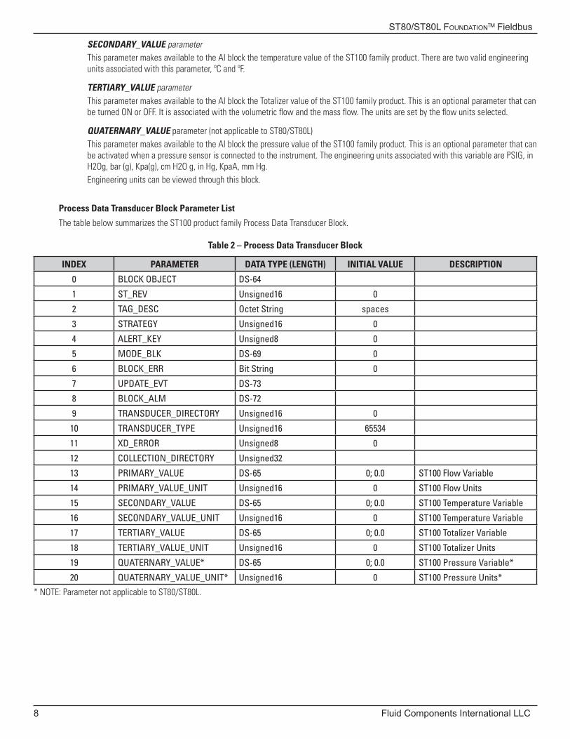
SECONDARY_VALUE parameterThis parameter makes available to the AI block the temperature value of the ST100 family product. There are two valid engineering units associated with this parameter, ºC and ºF.
TERTIARY_VALUE parameterThis parameter makes available to the AI block the Totalizer value of the ST100 family product. This is an optional parameter that can be turned ON or OFF. It is associated with the volumetric flow and the mass flow. The units are set by the flow units selected.
QUATERNARY_VALUE parameter (not applicable to ST80/ST80L)This parameter makes available to the AI block the pressure value of the ST100 family product. This is an optional parameter that can be activated when a pressure sensor is connected to the instrument. The engineering units associated with this variable are PSIG, in H2Og, bar (g), Kpa(g), cm H2O g, in Hg, KpaA, mm Hg. Engineering units can be viewed through this block.
Process Data Transducer Block Parameter List
The table below summarizes the ST100 product family Process Data Transducer Block.
Table 2 – Process Data Transducer Block
INDEX PARAMETER DATA TYPE (LENGTH) INITIAL VALUE DESCRIPTION
0 BLOCK OBJECT DS-64
1 ST_REV Unsigned16 0
2 TAG_DESC Octet String spaces
3 STRATEGY Unsigned16 0
4 ALERT_KEY Unsigned8 0
5 MODE_BLK DS-69 0
6 BLOCK_ERR Bit String 0
7 UPDATE_EVT DS-73
8 BLOCK_ALM DS-72
9 TRANSDUCER_DIRECTORY Unsigned16 0
10 TRANSDUCER_TYPE Unsigned16 65534
11 XD_ERROR Unsigned8 0
12 COLLECTION_DIRECTORY Unsigned32
13 PRIMARY_VALUE DS-65 0; 0.0 ST100 Flow Variable
14 PRIMARY_VALUE_UNIT Unsigned16 0 ST100 Flow Units
15 SECONDARY_VALUE DS-65 0; 0.0 ST100 Temperature Variable
16 SECONDARY_VALUE_UNIT Unsigned16 0 ST100 Temperature Variable
17 TERTIARY_VALUE DS-65 0; 0.0 ST100 Totalizer Variable
18 TERTIARY_VALUE_UNIT Unsigned16 0 ST100 Totalizer Units
19 QUATERNARY_VALUE* DS-65 0; 0.0 ST100 Pressure Variable*
20 QUATERNARY_VALUE_UNIT* Unsigned16 0 ST100 Pressure Units*
* NOTE: Parameter not applicable to ST80/ST80L.
ST80/ST80L Foundation™ Fieldbus
Fluid Components International LLC 9
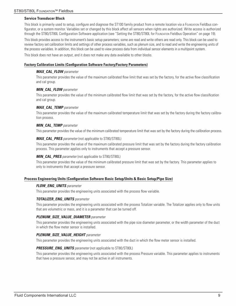
Service Transducer Block
This block is primarily used to setup, configure and diagnose the ST100 family product from a remote location via a Foundation Fieldbus con-figurator, or a system monitor. Variables set or changed by this block affect all sensors when rights are authorized. Write access is authorized through the ST80/ST80L Configuration Software application (see “Setting the ST80/ST80L for Foundation Fieldbus Operation” on page 19).
This block provides access to the instrument’s basic setup parameters; some are read and write others are read only. This block can be used to review factory set calibration limits and settings of other process variables, such as plenum size, and to read and write the engineering units of the process variables. In addition, this block can be used to view process data from individual sensor elements in a multipoint system.
This block does not have an output, and it does not make any data available to other blocks.
Factory Calibration Limits (Configuration Software Factory/Factory Parameters)
MAX_CAL_FLOW parameterThis parameter provides the value of the maximum calibrated flow limit that was set by the factory, for the active flow classification and cal group.
MIN_CAL_FLOW parameterThis parameter provides the value of the minimum calibrated flow limit that was set by the factory, for the active flow classification and cal group.
MAX_CAL_TEMP parameterThis parameter provides the value of the maximum calibrated temperature limit that was set by the factory during the factory calibra-tion process.
MIN_CAL_TEMP parameterThis parameter provides the value of the minimum calibrated temperature limit that was set by the factory during the calibration process.
MAX_CAL_PRES parameter (not applicable to ST80/ST80L)This parameter provides the value of the maximum calibrated pressure limit that was set by the factory during the factory calibration process. This parameter applies only to instruments that accept a pressure sensor.
MIN_CAL_PRES parameter (not applicable to ST80/ST80L)This parameter provides the value of the minimum calibrated pressure limit that was set by the factory. This parameter applies to only to instruments that accept a pressure sensor.
Process Engineering Units (Configuration Software Basic Setup/Units & Basic Setup/Pipe Size)
FLOW_ENG_UNITS parameterThis parameter provides the engineering units associated with the process flow variable.
TOTALIZER_ENG_UNITS parameterThis parameter provides the engineering units associated with the process Totalizer variable. The Totalizer applies only to flow units that are volumetric or mass, and it is a parameter that can be turned off.
PLENUM_SIZE_VALUE_DIAMETER parameterThis parameter provides the engineering units associated with the pipe size diameter parameter, or the width parameter of the duct in which the flow meter sensor is installed.
PLENUM_SIZE_VALUE_HEIGHT parameterThis parameter provides the engineering units associated with the duct in which the flow meter sensor is installed.
PRESSURE_ENG_UNITS parameter (not applicable to ST80/ST80L)This parameter provides the engineering units associated with the process Pressure variable. This parameter applies to instruments that have a pressure sensor, and may not be active in all instruments.
ST80/ST80L Foundation™ Fieldbus
10 Fluid Components International LLC
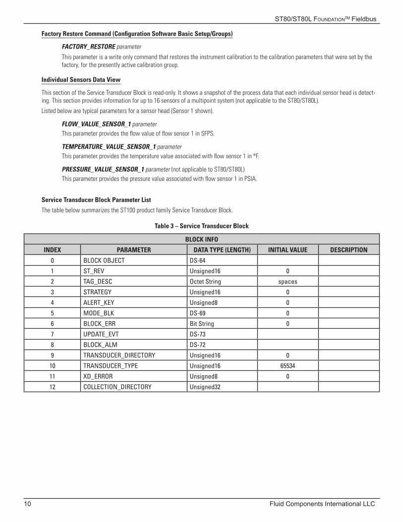
Factory Restore Command (Configuration Software Basic Setup/Groups)
FACTORY_RESTORE parameter
This parameter is a write only command that restores the instrument calibration to the calibration parameters that were set by the factory, for the presently active calibration group.
Individual Sensors Data View
This section of the Service Transducer Block is read-only. It shows a snapshot of the process data that each individual sensor head is detect-ing. This section provides information for up to 16 sensors of a multipoint system (not applicable to the ST80/ST80L).
Listed below are typical parameters for a sensor head (Sensor 1 shown).
FLOW_VALUE_SENSOR_1 parameterThis parameter provides the flow value of flow sensor 1 in SFPS.
TEMPERATURE_VALUE_SENSOR_1 parameterThis parameter provides the temperature value associated with flow sensor 1 in °F.
PRESSURE_VALUE_SENSOR_1 parameter (not applicable to ST80/ST80L)This parameter provides the pressure value associated with flow sensor 1 in PSIA.
Service Transducer Block Parameter List
The table below summarizes the ST100 product family Service Transducer Block.
Table 3 – Service Transducer Block
BLOCK INFO
INDEX PARAMETER DATA TYPE (LENGTH) INITIAL VALUE DESCRIPTION
0 BLOCK OBJECT DS-64
1 ST_REV Unsigned16 0
2 TAG_DESC Octet String spaces
3 STRATEGY Unsigned16 0
4 ALERT_KEY Unsigned8 0
5 MODE_BLK DS-69 0
6 BLOCK_ERR Bit String 0
7 UPDATE_EVT DS-73
8 BLOCK_ALM DS-72
9 TRANSDUCER_DIRECTORY Unsigned16 0
10 TRANSDUCER_TYPE Unsigned16 65534
11 XD_ERROR Unsigned8 0
12 COLLECTION_DIRECTORY Unsigned32
ST80/ST80L Foundation™ Fieldbus
Fluid Components International LLC 11
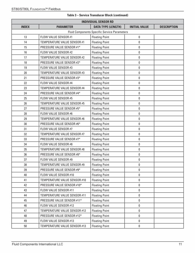
Table 3 – Service Transducer Block (continued)
INDIVIDUAL SENSOR RD
INDEX PARAMETER DATA TYPE (LENGTH) INITIAL VALUE DESCRIPTION
Fluid Components Specific Service Parameters
13 FLOW VALUE SENSOR #1 Floating Point 0
14 TEMPERATURE VALUE SENSOR #1 Floating Point 0
15 PRESSURE VALUE SENSOR #1* Floating Point 0
16 FLOW VALUE SENSOR #2 Floating Point 0
17 TEMPERATURE VALUE SENSOR #2 Floating Point 0
18 PRESSURE VALUE SENSOR #2* Floating Point 0
19 FLOW VALUE SENSOR #3 Floating Point 0
20 TEMPERATURE VALUE SENSOR #3 Floating Point 0
21 PRESSURE VALUE SENSOR #3* Floating Point 0
22 FLOW VALUE SENSOR #4 Floating Point 0
23 TEMPERATURE VALUE SENSOR #4 Floating Point 0
24 PRESSURE VALUE SENSOR #4* Floating Point 0
25 FLOW VALUE SENSOR #5 Floating Point 0
26 TEMPERATURE VALUE SENSOR #5 Floating Point 0
27 PRESSURE VALUE SENSOR #5* Floating Point 0
28 FLOW VALUE SENSOR #6 Floating Point 0
29 TEMPERATURE VALUE SENSOR #6 Floating Point 0
30 PRESSURE VALUE SENSOR #6* Floating Point 0
31 FLOW VALUE SENSOR #7 Floating Point 0
32 TEMPERATURE VALUE SENSOR #7 Floating Point 0
33 PRESSURE VALUE SENSOR #7* Floating Point 0
34 FLOW VALUE SENSOR #8 Floating Point 0
35 TEMPERATURE VALUE SENSOR #8 Floating Point 0
36 PRESSURE VALUE SENSOR #8* Floating Point 0
37 FLOW VALUE SENSOR #9 Floating Point 0
38 TEMPERATURE VALUE SENSOR #9 Floating Point 0
39 PRESSURE VALUE SENSOR #9* Floating Point 0
40 FLOW VALUE SENSOR #10 Floating Point 0
41 TEMPERATURE VALUE SENSOR #10 Floating Point 0
42 PRESSURE VALUE SENSOR #10* Floating Point 0
43 FLOW VALUE SENSOR #11 Floating Point 0
44 TEMPERATURE VALUE SENSOR #11 Floating Point 0
45 PRESSURE VALUE SENSOR #11* Floating Point 0
46 FLOW VALUE SENSOR #12 Floating Point 0
47 TEMPERATURE VALUE SENSOR #12 Floating Point 0
48 PRESSURE VALUE SENSOR #12* Floating Point 0
49 FLOW VALUE SENSOR #13 Floating Point 0
50 TEMPERATURE VALUE SENSOR #13 Floating Point 0
ST80/ST80L Foundation™ Fieldbus
12 Fluid Components International LLC
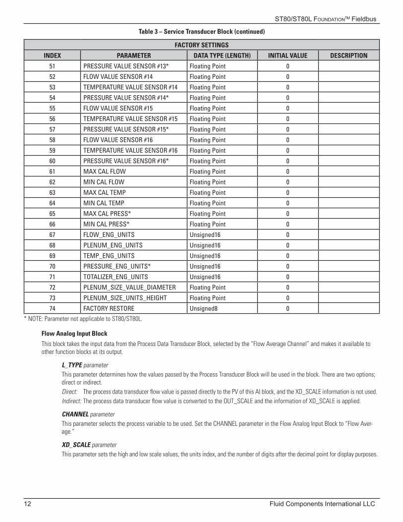
Table 3 – Service Transducer Block (continued)
FACTORY SETTINGS
INDEX PARAMETER DATA TYPE (LENGTH) INITIAL VALUE DESCRIPTION
51 PRESSURE VALUE SENSOR #13* Floating Point 0
52 FLOW VALUE SENSOR #14 Floating Point 0
53 TEMPERATURE VALUE SENSOR #14 Floating Point 0
54 PRESSURE VALUE SENSOR #14* Floating Point 0
55 FLOW VALUE SENSOR #15 Floating Point 0
56 TEMPERATURE VALUE SENSOR #15 Floating Point 0
57 PRESSURE VALUE SENSOR #15* Floating Point 0
58 FLOW VALUE SENSOR #16 Floating Point 0
59 TEMPERATURE VALUE SENSOR #16 Floating Point 0
60 PRESSURE VALUE SENSOR #16* Floating Point 0
61 MAX CAL FLOW Floating Point 0
62 MIN CAL FLOW Floating Point 0
63 MAX CAL TEMP Floating Point 0
64 MIN CAL TEMP Floating Point 0
65 MAX CAL PRESS* Floating Point 0
66 MIN CAL PRESS* Floating Point 0
67 FLOW_ENG_UNITS Unsigned16 0
68 PLENUM_ENG_UNITS Unsigned16 0
69 TEMP_ENG_UNITS Unsigned16 0
70 PRESSURE_ENG_UNITS* Unsigned16 0
71 TOTALIZER_ENG_UNITS Unsigned16 0
72 PLENUM_SIZE_VALUE_DIAMETER Floating Point 0
73 PLENUM_SIZE_UNITS_HEIGHT Floating Point 0
74 FACTORY RESTORE Unsigned8 0
* NOTE: Parameter not applicable to ST80/ST80L.
Flow Analog Input Block
This block takes the input data from the Process Data Transducer Block, selected by the “Flow Average Channel” and makes it available to other function blocks at its output.
L_TYPE parameterThis parameter determines how the values passed by the Process Transducer Block will be used in the block. There are two options; direct or indirect. Direct: The process data transducer flow value is passed directly to the PV of this AI block, and the XD_SCALE information is not used. Indirect: The process data transducer flow value is converted to the OUT_SCALE and the information of XD_SCALE is applied.
CHANNEL parameterThis parameter selects the process variable to be used. Set the CHANNEL parameter in the Flow Analog Input Block to “Flow Aver-age.”
XD_SCALE parameterThis parameter sets the high and low scale values, the units index, and the number of digits after the decimal point for display purposes.
ST80/ST80L Foundation™ Fieldbus
Fluid Components International LLC 13
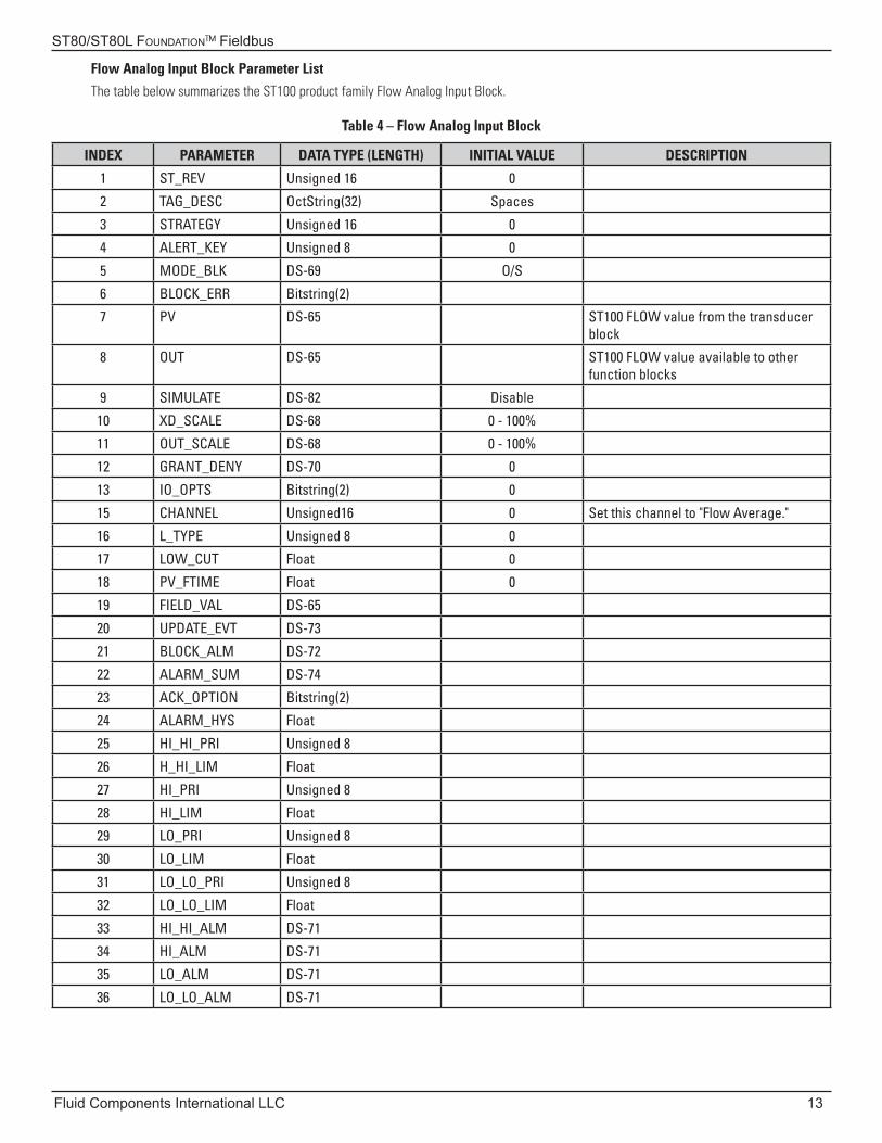
Flow Analog Input Block Parameter List
The table below summarizes the ST100 product family Flow Analog Input Block.
Table 4 – Flow Analog Input Block
INDEX PARAMETER DATA TYPE (LENGTH) INITIAL VALUE DESCRIPTION
1 ST_REV Unsigned 16 0
2 TAG_DESC OctString(32) Spaces
3 STRATEGY Unsigned 16 0
4 ALERT_KEY Unsigned 8 0
5 MODE_BLK DS-69 O/S
6 BLOCK_ERR Bitstring(2)
7 PV DS-65 ST100 FLOW value from the transducer block
8 OUT DS-65 ST100 FLOW value available to other function blocks
9 SIMULATE DS-82 Disable
10 XD_SCALE DS-68 0 - 100%
11 OUT_SCALE DS-68 0 - 100%
12 GRANT_DENY DS-70 0
13 IO_OPTS Bitstring(2) 0
15 CHANNEL Unsigned16 0 Set this channel to "Flow Average."
16 L_TYPE Unsigned 8 0
17 LOW_CUT Float 0
18 PV_FTIME Float 0
19 FIELD_VAL DS-65
20 UPDATE_EVT DS-73
21 BLOCK_ALM DS-72
22 ALARM_SUM DS-74
23 ACK_OPTION Bitstring(2)
24 ALARM_HYS Float
25 HI_HI_PRI Unsigned 8
26 H_HI_LIM Float
27 HI_PRI Unsigned 8
28 HI_LIM Float
29 LO_PRI Unsigned 8
30 LO_LIM Float
31 LO_LO_PRI Unsigned 8
32 LO_LO_LIM Float
33 HI_HI_ALM DS-71
34 HI_ALM DS-71
35 LO_ALM DS-71
36 LO_LO_ALM DS-71
ST80/ST80L Foundation™ Fieldbus
14 Fluid Components International LLC
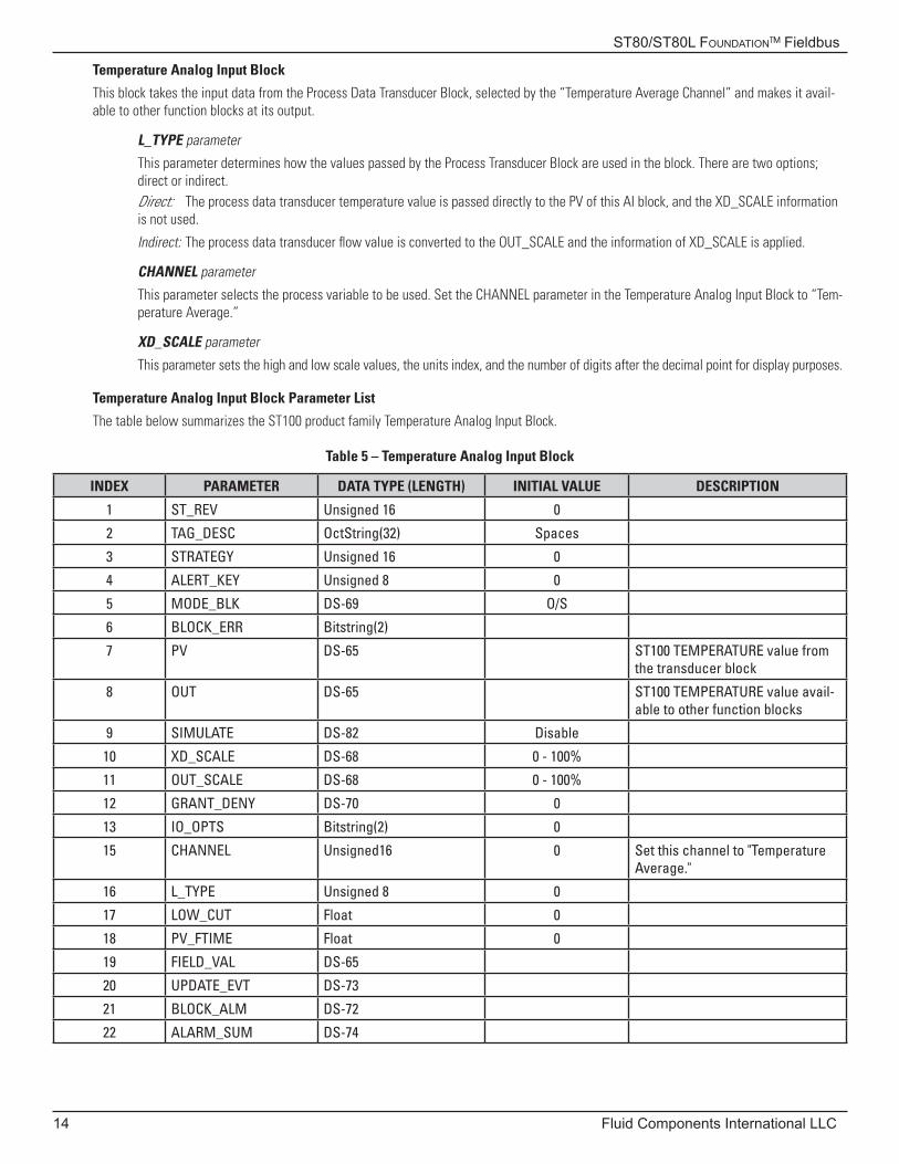
Temperature Analog Input Block
This block takes the input data from the Process Data Transducer Block, selected by the “Temperature Average Channel” and makes it avail-able to other function blocks at its output.
L_TYPE parameter
This parameter determines how the values passed by the Process Transducer Block are used in the block. There are two options; direct or indirect.Direct: The process data transducer temperature value is passed directly to the PV of this AI block, and the XD_SCALE information is not used.
Indirect: The process data transducer flow value is converted to the OUT_SCALE and the information of XD_SCALE is applied.
CHANNEL parameter
This parameter selects the process variable to be used. Set the CHANNEL parameter in the Temperature Analog Input Block to “Tem-perature Average.”
XD_SCALE parameter
This parameter sets the high and low scale values, the units index, and the number of digits after the decimal point for display purposes.
Temperature Analog Input Block Parameter List
The table below summarizes the ST100 product family Temperature Analog Input Block.
Table 5 – Temperature Analog Input Block
INDEX PARAMETER DATA TYPE (LENGTH) INITIAL VALUE DESCRIPTION
1 ST_REV Unsigned 16 0
2 TAG_DESC OctString(32) Spaces
3 STRATEGY Unsigned 16 0
4 ALERT_KEY Unsigned 8 0
5 MODE_BLK DS-69 O/S
6 BLOCK_ERR Bitstring(2)
7 PV DS-65 ST100 TEMPERATURE value from the transducer block
8 OUT DS-65 ST100 TEMPERATURE value avail-able to other function blocks
9 SIMULATE DS-82 Disable
10 XD_SCALE DS-68 0 - 100%
11 OUT_SCALE DS-68 0 - 100%
12 GRANT_DENY DS-70 0
13 IO_OPTS Bitstring(2) 0
15 CHANNEL Unsigned16 0 Set this channel to "Temperature Average."
16 L_TYPE Unsigned 8 0
17 LOW_CUT Float 0
18 PV_FTIME Float 0
19 FIELD_VAL DS-65
20 UPDATE_EVT DS-73
21 BLOCK_ALM DS-72
22 ALARM_SUM DS-74

ST80/ST80L Foundation™ Fieldbus
Fluid Components International LLC 15
Table 5 – Temperature Analog Input Block (continued)
INDEX PARAMETER DATA TYPE (LENGTH) INITIAL VALUE DESCRIPTION
23 ACK_OPTION Bitstring(2)
24 ALARM_HYS Float
25 HI_HI_PRI Unsigned 8
26 H_HI_LIM Float
27 HI_PRI Unsigned 8
28 HI_LIM Float
29 LO_PRI Unsigned 8
30 LO_LIM Float
31 LO_LO_PRI Unsigned 8
32 LO_LO_LIM Float
33 HI_HI_ALM DS-71
34 HI_ALM DS-71
35 LO_ALM DS-71
36 LO_LO_ALM DS-71
Totalizer Analog Input Block
This block takes the input data from the Process Data Transducer Block, selected by the “Totalizer Average Channel” and makes it available to other function blocks at its output.
L_TYPE parameterThis parameter determines how the values passed by the Process Transducer Block are used in the block. There are two options; direct or indirect. Direct The process data transducer totalizer value is passed directly to the PV of this AI block, and the XD_SCALE information is not used.
Indirect The process data transducer totalizer value is converted to the OUT_SCALE and the information of XD_SCALE is applied.
CHANNEL parameter
This parameter selects the process variable to be used. Set the CHANNEL parameter in the Totalizer Analog Input Block to “Totalizer Average.”
XD_SCALE parameter
This parameter sets the high and low scale values, the units index, and the number of digits after the decimal point for display purposes.
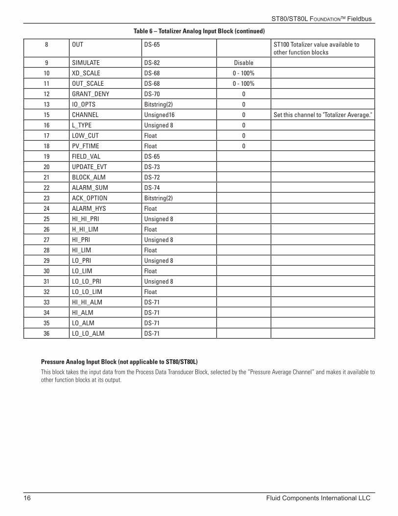
Totalizer Analog Input Block Parameter List
The table below summarizes the ST100 product family Totalizer Analog Input Block.
Table 6 – Totalizer Analog Input Block
INDEX PARAMETER DATA TYPE (LENGTH) INITIAL VALUE DESCRIPTION
1 ST_REV Unsigned 16 0
2 TAG_DESC OctString(32) Spaces
3 STRATEGY Unsigned 16 0
4 ALERT_KEY Unsigned 8 0
5 MODE_BLK DS-69 O/S
6 BLOCK_ERR Bitstring(2)
7 PV DS-65 ST100 Totalizer value from the trans-ducer block
ST80/ST80L Foundation™ Fieldbus
16 Fluid Components International LLC
Table 6 – Totalizer Analog Input Block (continued)
8 OUT DS-65 ST100 Totalizer value available to other function blocks
9 SIMULATE DS-82 Disable
10 XD_SCALE DS-68 0 - 100%
11 OUT_SCALE DS-68 0 - 100%
12 GRANT_DENY DS-70 0
13 IO_OPTS Bitstring(2) 0
15 CHANNEL Unsigned16 0 Set this channel to "Totalizer Average."
16 L_TYPE Unsigned 8 0
17 LOW_CUT Float 0
18 PV_FTIME Float 0
19 FIELD_VAL DS-65
20 UPDATE_EVT DS-73
21 BLOCK_ALM DS-72
22 ALARM_SUM DS-74
23 ACK_OPTION Bitstring(2)
24 ALARM_HYS Float
25 HI_HI_PRI Unsigned 8
26 H_HI_LIM Float
27 HI_PRI Unsigned 8
28 HI_LIM Float
29 LO_PRI Unsigned 8
30 LO_LIM Float
31 LO_LO_PRI Unsigned 8
32 LO_LO_LIM Float
33 HI_HI_ALM DS-71
34 HI_ALM DS-71
35 LO_ALM DS-71
36 LO_LO_ALM DS-71
Pressure Analog Input Block (not applicable to ST80/ST80L)
This block takes the input data from the Process Data Transducer Block, selected by the “Pressure Average Channel” and makes it available to other function blocks at its output.
ST80/ST80L Foundation™ Fieldbus
Fluid Components International LLC 17
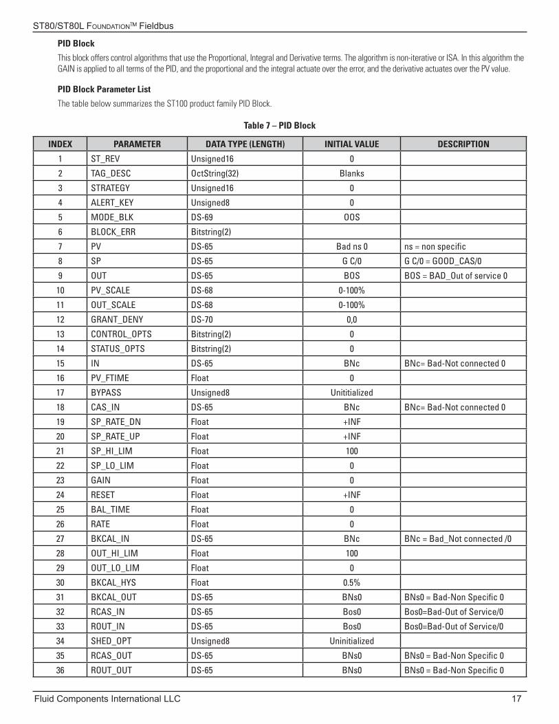
PID Block
This block offers control algorithms that use the Proportional, Integral and Derivative terms. The algorithm is non-iterative or ISA. In this algorithm the GAIN is applied to all terms of the PID, and the proportional and the integral actuate over the error, and the derivative actuates over the PV value.
PID Block Parameter List
The table below summarizes the ST100 product family PID Block.
Table 7 – PID Block
INDEX PARAMETER DATA TYPE (LENGTH) INITIAL VALUE DESCRIPTION
1 ST_REV Unsigned16 0
2 TAG_DESC OctString(32) Blanks
3 STRATEGY Unsigned16 0
4 ALERT_KEY Unsigned8 0
5 MODE_BLK DS-69 OOS
6 BLOCK_ERR Bitstring(2)
7 PV DS-65 Bad ns 0 ns = non specific
8 SP DS-65 G C/0 G C/0 = GOOD_CAS/0
9 OUT DS-65 BOS BOS = BAD_Out of service 0
10 PV_SCALE DS-68 0-100%
11 OUT_SCALE DS-68 0-100%
12 GRANT_DENY DS-70 0,0
13 CONTROL_OPTS Bitstring(2) 0
14 STATUS_OPTS Bitstring(2) 0
15 IN DS-65 BNc BNc= Bad-Not connected 0
16 PV_FTIME Float 0
17 BYPASS Unsigned8 Unititialized
18 CAS_IN DS-65 BNc BNc= Bad-Not connected 0
19 SP_RATE_DN Float +INF
20 SP_RATE_UP Float +INF
21 SP_HI_LIM Float 100
22 SP_LO_LIM Float 0
23 GAIN Float 0
24 RESET Float +INF
25 BAL_TIME Float 0
26 RATE Float 0
27 BKCAL_IN DS-65 BNc BNc = Bad_Not connected /0
28 OUT_HI_LIM Float 100
29 OUT_LO_LIM Float 0
30 BKCAL_HYS Float 0.5%
31 BKCAL_OUT DS-65 BNs0 BNs0 = Bad-Non Specific 0
32 RCAS_IN DS-65 Bos0 Bos0=Bad-Out of Service/0
33 ROUT_IN DS-65 Bos0 Bos0=Bad-Out of Service/0
34 SHED_OPT Unsigned8 Uninitialized
35 RCAS_OUT DS-65 BNs0 BNs0 = Bad-Non Specific 0
36 ROUT_OUT DS-65 BNs0 BNs0 = Bad-Non Specific 0
ST80/ST80L Foundation™ Fieldbus
18 Fluid Components International LLC
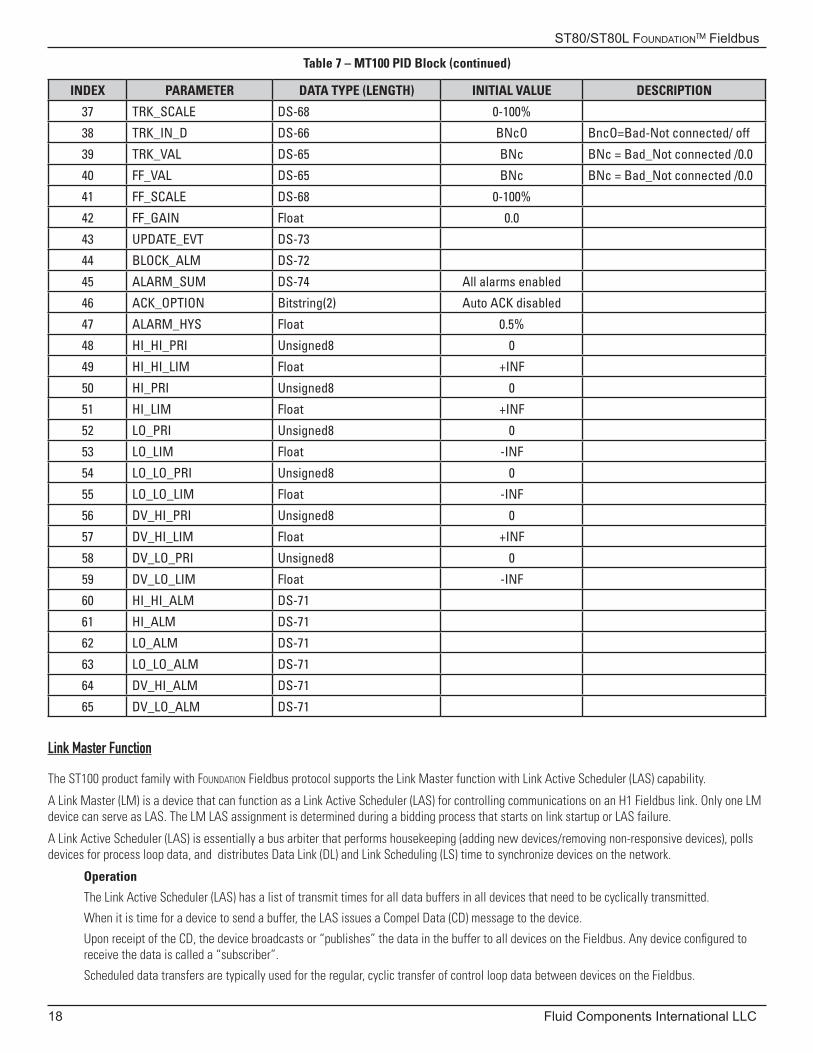
Table 7 – MT100 PID Block (continued)
INDEX PARAMETER DATA TYPE (LENGTH) INITIAL VALUE DESCRIPTION
37 TRK_SCALE DS-68 0-100%
38 TRK_IN_D DS-66 BNcO BncO=Bad-Not connected/ off
39 TRK_VAL DS-65 BNc BNc = Bad_Not connected /0.0
40 FF_VAL DS-65 BNc BNc = Bad_Not connected /0.0
41 FF_SCALE DS-68 0-100%
42 FF_GAIN Float 0.0
43 UPDATE_EVT DS-73
44 BLOCK_ALM DS-72
45 ALARM_SUM DS-74 All alarms enabled
46 ACK_OPTION Bitstring(2) Auto ACK disabled
47 ALARM_HYS Float 0.5%
48 HI_HI_PRI Unsigned8 0
49 HI_HI_LIM Float +INF
50 HI_PRI Unsigned8 0
51 HI_LIM Float +INF
52 LO_PRI Unsigned8 0
53 LO_LIM Float -INF
54 LO_LO_PRI Unsigned8 0
55 LO_LO_LIM Float -INF
56 DV_HI_PRI Unsigned8 0
57 DV_HI_LIM Float +INF
58 DV_LO_PRI Unsigned8 0
59 DV_LO_LIM Float -INF
60 HI_HI_ALM DS-71
61 HI_ALM DS-71
62 LO_ALM DS-71
63 LO_LO_ALM DS-71
64 DV_HI_ALM DS-71
65 DV_LO_ALM DS-71
Link Master Function
The ST100 product family with Foundation Fieldbus protocol supports the Link Master function with Link Active Scheduler (LAS) capability.
A Link Master (LM) is a device that can function as a Link Active Scheduler (LAS) for controlling communications on an H1 Fieldbus link. Only one LM device can serve as LAS. The LM LAS assignment is determined during a bidding process that starts on link startup or LAS failure.
A Link Active Scheduler (LAS) is essentially a bus arbiter that performs housekeeping (adding new devices/removing non-responsive devices), polls devices for process loop data, and distributes Data Link (DL) and Link Scheduling (LS) time to synchronize devices on the network.
Operation
The Link Active Scheduler (LAS) has a list of transmit times for all data buffers in all devices that need to be cyclically transmitted.
When it is time for a device to send a buffer, the LAS issues a Compel Data (CD) message to the device.
Upon receipt of the CD, the device broadcasts or “publishes” the data in the buffer to all devices on the Fieldbus. Any device configured to receive the data is called a “subscriber”.
Scheduled data transfers are typically used for the regular, cyclic transfer of control loop data between devices on the Fieldbus.
ST80/ST80L Foundation™ Fieldbus
Fluid Components International LLC 19
Configuring Foundation Fieldbus
For details on ST80/ST80L installation and operation, see the main manual document number 06EN003490.
Setting the ST80/ST80L for Foundation Fieldbus Operation
Note: The instrument requires no configuration if ordered with the Foundation Fieldbus option.
The ST80/ST80L Configuration Software application is used to select the instrument’s digital communication protocol.
Using the USB cable supplied with the instrument, connect the ST80/ST80L USB port to a USB port on the PC on which the ST80/ST80L configurator software is installed.
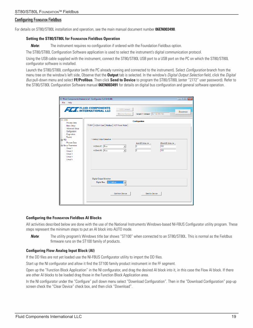
Launch the ST80/ST80L configurator (with the PC already running and connected to the instrument). Select Configuration branch from the menu tree on the window’s left side, Observe that the Output tab is selected. In the window’s Digital Output Selection field, click the Digital Bus pull-down menu and select FF/Profibus. Then click Send to Device to program the ST80/ST80L (enter “2772” user password). Refer to the ST80/ST80L Configuration Software manual 06EN003491 for details on digital bus configuration and general software operation.
Configuring the Foundation Fieldbus AI Blocks
All activities described below are done with the use of the National Instruments Windows-based NI-FBUS Configurator utility program. These steps represent the minimum steps to put an AI block into AUTO mode.
Note: The utility program’s Windows title bar shows “ST100” when connected to an ST80/ST80L. This is normal as the Fieldbus firmware runs on the ST100 family of products.
Configuring Flow Analog Input Block (AI)
If the DD files are not yet loaded use the NI-FBUS Configurator utility to import the DD files.
Start up the NI configurator and allow it find the ST100 family product instrument in the FF segment.
Open up the “Function Block Application” in the NI configurator, and drag the desired AI block into it, in this case the Flow AI block. If there are other AI blocks to be loaded drag those in the Function Block Application area.
In the NI configurator under the “Configure” pull down menu select “Download Configuration”. Then in the “Download Configuration” pop-up screen check the “Clear Device” check box, and then click “Download”.
ST80/ST80L Foundation™ Fieldbus
20 Fluid Components International LLC
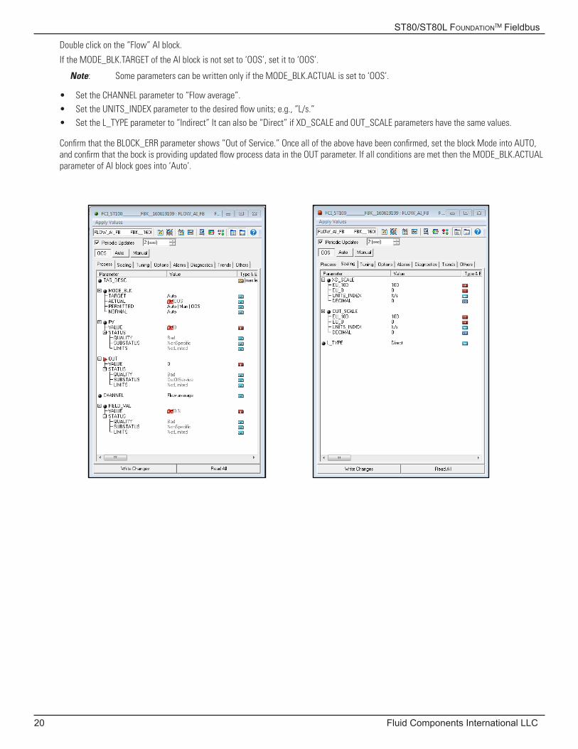
Double click on the “Flow” AI block.
If the MODE_BLK.TARGET of the AI block is not set to ‘OOS’, set it to ‘OOS’.
Note: Some parameters can be written only if the MODE_BLK.ACTUAL is set to ‘OOS’.
• Set the CHANNEL parameter to “Flow average”.• Set the UNITS_INDEX parameter to the desired flow units; e.g., “L/s.”• Set the L_TYPE parameter to “Indirect” It can also be “Direct” if XD_SCALE and OUT_SCALE parameters have the same values.
Confirm that the BLOCK_ERR parameter shows “Out of Service.” Once all of the above have been confirmed, set the block Mode into AUTO, and confirm that the bock is providing updated flow process data in the OUT parameter. If all conditions are met then the MODE_BLK.ACTUAL parameter of AI block goes into ‘Auto’.
ST80/ST80L Foundation™ Fieldbus
Fluid Components International LLC 21
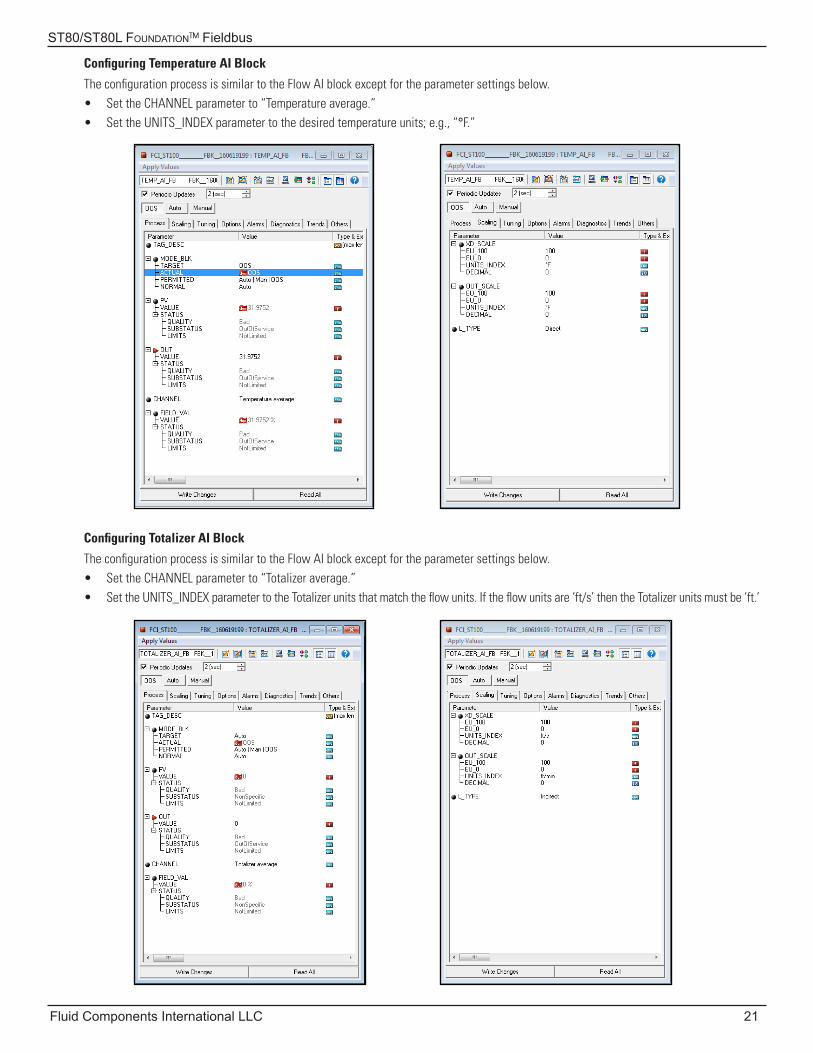
Configuring Temperature AI Block
The configuration process is similar to the Flow AI block except for the parameter settings below.• Set the CHANNEL parameter to “Temperature average.”• Set the UNITS_INDEX parameter to the desired temperature units; e.g., “°F.”
Configuring Totalizer AI Block
The configuration process is similar to the Flow AI block except for the parameter settings below.• Set the CHANNEL parameter to “Totalizer average.”• Set the UNITS_INDEX parameter to the Totalizer units that match the flow units. If the flow units are ‘ft/s’ then the Totalizer units must be ‘ft.’
ST80/ST80L Foundation™ Fieldbus
22 Fluid Components International LLC
Using the Foundation Fieldbus Service Transducer Block
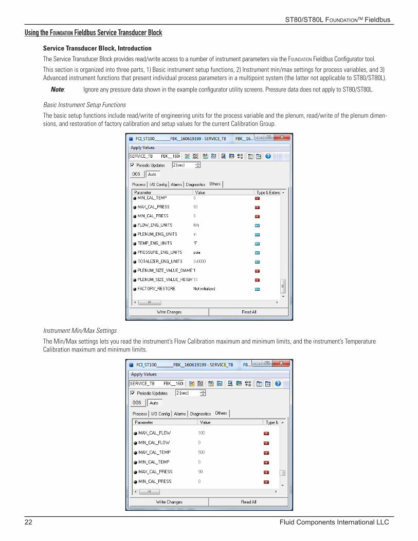
Service Transducer Block, Introduction
The Service Transducer Block provides read/write access to a number of instrument parameters via the Foundation Fieldbus Configurator tool.
This section is organized into three parts, 1) Basic instrument setup functions, 2) Instrument min/max settings for process variables, and 3) Advanced instrument functions that present individual process parameters in a multipoint system (the latter not applicable to ST80/ST80L).
Note: Ignore any pressure data shown in the example configurator utility screens. Pressure data does not apply to ST80/ST80L.
Basic Instrument Setup Functions
The basic setup functions include read/write of engineering units for the process variable and the plenum, read/write of the plenum dimen-sions, and restoration of factory calibration and setup values for the current Calibration Group.
Instrument Min/Max Settings
The Min/Max settings lets you read the instrument’s Flow Calibration maximum and minimum limits, and the instrument’s Temperature Calibration maximum and minimum limits.
ST80/ST80L Foundation™ Fieldbus
Fluid Components International LLC 23
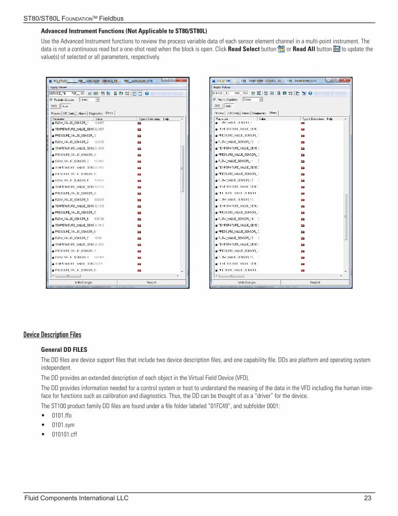
Advanced Instrument Functions (Not Applicable to ST80/ST80L)
Use the Advanced Instrument functions to review the process variable data of each sensor element channel in a multi-point instrument. The data is not a continuous read but a one-shot read when the block is open. Click Read Select button or Read All button to update the value(s) of selected or all parameters, respectively.
Device Description Files
General DD FILES
The DD files are device support files that include two device description files, and one capability file. DDs are platform and operating system independent.
The DD provides an extended description of each object in the Virtual Field Device (VFD).
The DD provides information needed for a control system or host to understand the meaning of the data in the VFD including the human inter-face for functions such as calibration and diagnostics. Thus, the DD can be thought of as a “driver” for the device.
The ST100 product family DD files are found under a file folder labeled “01FC49”, and subfolder 0001: • 0101.ffo• 0101.sym• 010101.cff
ST80/ST80L Foundation™ Fieldbus
24 Fluid Components International LLC
Emerson 475 Field Communicator
The Emerson Communicator uses the Foundation Fieldbus DDP files to interface with the Foundation Fieldbus device. These files must be loaded into the Emerson Fieldbus Communicator.
The ST100 product family Foundation Fieldbus DDP files are found under a file folder labeled EMERSON_475_FILES, and subfolder 01FC49\0001:
• 01FC49000101.fdd• 01FFC9000101.fhd• 0101.ffo• 0101.sym• 010101.cff
Load these files in the C:\01FC49\0001 directory.
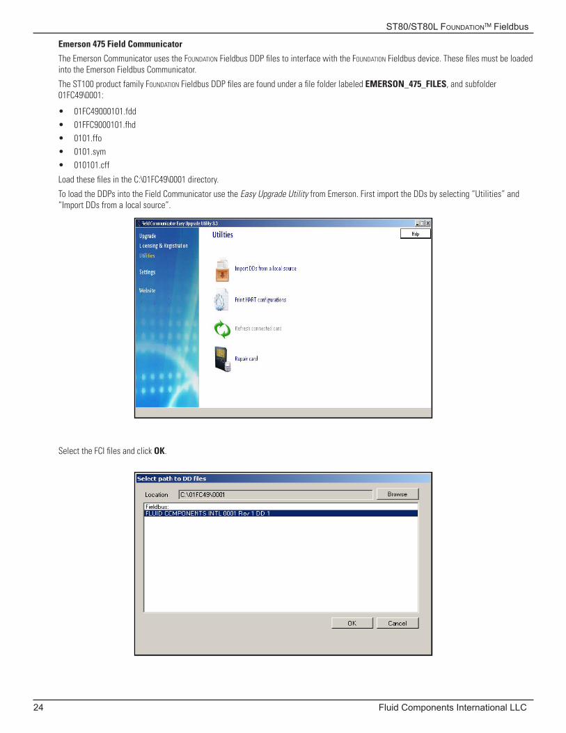
To load the DDPs into the Field Communicator use the Easy Upgrade Utility from Emerson. First import the DDs by selecting “Utilities” and “Import DDs from a local source”.
Select the FCI files and click OK.
ST80/ST80L Foundation™ Fieldbus
Fluid Components International LLC 25
Technical Characteristics
Manufacturer ID: 01FC49
Output Signal: H1 compliant to IEC 61158-2, bus powered.Integral reverse polarity protection.
Data transmission rate: 31.25 kBit/s, voltage mode
Signal coding: Manchester II
LAS function: LAS function supported
Supported communication: Publisher, Subscriber
H1 Profile Class: 31PS, 32L
H1 Device Class: Link Master
Function Blocks: Process Data TBService Data TBFlow AI Temperature AI Totalizer AIPID
Certification: Register Instrument (Test Campaign # IT071900)
Register Features: Alarms and EventsFunction Blocks (1-RB2(e), 4-AI(s), 1-PID(s), 2-TB(s))LinkingTrendingMuti-bit Alert ReportingField Diagnostics
ST80/ST80L Foundation™ Fieldbus
26 Fluid Components International LLC
INTENTIONALLY LEFT BLANK
ST80/ST80L Foundation™ Fieldbus
Fluid Components International LLC 27
Customer Service/Technical Support
FCI provides full in-house technical support. Additional technical representation is also provided by FCI field representatives. Before contact-ing a field or in-house representative, please perform the troubleshooting techniques outlined in this document.
By MailFluid Components International LLC1755 La Costa Meadows Dr.San Marcos, CA 92078-5115 USAAttn: Customer Service Department
By PhoneContact the area FCI regional representative. If a field representative is unable to be contacted or if a situation is unable to be resolved, contact the FCI Customer Service Department toll free at 1 (800) 854-1993.
By FaxTo describe problems in a graphical or pictorial manner, send a fax including a phone or fax number to the regional representative. Again, FCI is available by facsimile if all possibilities have been exhausted with the authorized factory representative. Our fax number is 1 (760) 736-6250; it is available 7 days a week, 24 hours a day.
By EmailFCI Customer Service can be contacted by email at: [email protected].
Describe the problem in detail making sure a telephone number and best time to be contacted is stated in the email.
International SupportFor product information or product support outside the contiguous United States, Alaska, or Hawaii, contact your country’s FCI International Representative or the one nearest to you.
After Hours SupportFor product information visit FCI at www.fluidcomponents.com. For product support call 1 (800) 854-1993 and follow the prerecorded instructions.
Point of ContactThe point of contact for service, or return of equipment to FCI is your authorized FCI sales/service office. To locate the office nearest you, visit the FCI website at www.fluidcomponents.com.

ST80/ST80L Foundation™ Fieldbus
28 Fluid Components International LLC
INTENTIONALLY LEFT BLANK
ST80/ST80L Foundation™ Fieldbus
Fluid Components International LLC 29
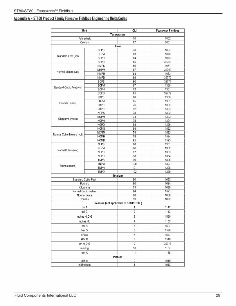
Appendix A - ST100 Product Family Foundation Fieldbus Engineering Units/Codes
Unit CLI Foundation FieldbusTemperature
Fahrenheit 70 1002Celsius 67 1001
Flow
Standard Feet (vel)
SFPS 70 1067SFPM 83 1070SFPH 84 1073SFPD 85 32768
Normal Meters (vel)
NMPS 86 1061NMPM 87 32769NMPH 88 1063NMPD 89 32770
Standard Cubic Feet (vol)
SCFS 90 32771SCFM 67 1360SCFH 72 1361SCFD 91 32772
Pounds (mass)
LBPS 80 1330LBPM 65 1331LBPH 76 1332LBPD 92 1333
Kilograms (mass)
KGPS 73 1322KGPM 74 1323KGPH 75 1324KGPD 93 1325
Normal Cubic Meters (vol)
NCMS 94 1522NCMM 79 1523NCMH 78 1524NCMD 95 1525
Normal Liters (vol)
NLPS 68 1351NLPM 96 1352NLPH 97 1353NLPD 98 1354
Tonnes (mass)
TNPS 99 1326TNPM 100 1327TNPH 101 1328TNPD 102 1329
TotalizerStandard Cubic Feet 90 1053
Pounds 80 1094Kilograms 73 1088
Normal Cubic meters 94 1521Normal Liters 68 1038
Tonnes 99 1092Pressure (not applicable to ST80/ST80L)
psi A 1 1142psi G 2 1143
inches H2O G 3 1560inches Hg 4 1155
bar A 5 1597bar G 6 1590kPa A 7 1547kPa G 8 1548
cm H2O G 9 32773mm Hg 10 1157torr A 11 1139
Plenuminches 0 1019
millimeters 1 1013

Fluid Components International LLC 06EN003492 Rev. A
ST80/ST80L Foundation™ Fieldbus
FCI’s Complete Customer Commitment. WorldwideISO 9001 and AS9100 Certified
Notice of Proprietary RightsThis document contains confidential technical data, including trade secrets and proprietary information which is the property of Fluid Components International LLC (FCI). Disclosure of this data to you is expressly conditioned upon your assent that its use is limited to use within your company only (and does not include manufacture or processing uses). Any other use is strictly prohibited without the prior written consent of FCI.
Visit FCI on the Worldwide Web: www.fluidcomponents.com
FCI World Headquarters1755 La Costa Meadows Drive | San Marcos, California 92078 USA | Phone: 760-744-6950 Toll Free (US): 800-854-1993 Fax: 760-736-6250
FCI EuropePersephonestraat 3-01 | 5047 TT Tilburg, The Netherlands | Phone: 31-13-5159989 Fax: 31-13-5799036
FCI Measurement and Control Technology (Beijing) Co., LTD | www.fluidcomponents.cnRoom 107, Xianfeng Building II, No.7 Kaituo Road, Shangdi IT Industry Base, Haidian District | Beijing 100085, P. R. ChinaPhone: 86-10-82782381 Fax: 86-10-58851152
© Copyright 2019 by Fluid Components International LLC. All rights reserved. FCI is a registered trademark of Fluid Components International LLC. Information subject to change without notice.