st. regis indian reservation. regis indian reservation potential drainage improvements for three...
TRANSCRIPT
AD-A203 335
St. Regis Indian ReservationPotential Drainage Improvementsfor Three Watersheds
Preparedfor the Department of the Interior,Bureau of Indian Affairs
US Armq Corps "LE L'% Eof Enqiinoers_uf+4ao District 0 5 JAN 198i ii f
December 1981
isq.
SECURITY CLAssIrIcA~lood or Yw4o& -- rscIhm Dat .aE
-place until residential or agricultural development of Watershed no. 3requires improved drainage.
SECURITlY CLASSIFICATION Of THIS PAGE(Wh.,i Date Enw~ed)
UNCLASSIFI=)SECuRITY CLASSIFICATION O
r iMS PAGE fiW Vosen ELnted) W %_4
REPORT DOCUMENTATION PAGE READ INSTRUCTIONS1. REPORT NUMBER 2. GOVI ACCESSION NO. I. RECIPIENT'S CATALOG NUER
A. ITLEr (nd S.11101e) S. TYPE OF REPORT a PERIOD COVERED
St. Regis Indian Reservation, Potential FinalDrainage Improvements for Three Watersheds. PERORING O REPORT
7. AUT4OR(
sI) 6. CONTRACT OR GRANT NUMBERI,)
P jRFORMING ORGANIZATION 46ME AND ADDRESS 10 PROGRAM ELEMENT. PROJECT. TASK
U.S. Army Engineer District, Buffalo AREA6oORK UNITNUMII-
1776 Niagara St.Buffalo, N.Y. 14207-3199
I. CONTROLLING OFFICE NAME AND ADDRESS 12 REPORT GATEDecember 1988
13 NUMBE1Q 2V PAGES
14. MONITORING AGENCY NAME I AD-DRESS(,I d ffePent tram Conr,-Iling Offire) iS SECURITY CLASS. (of thls repor)
UnclassifiedI. DECLASSIFICATION 'DOWNGRADING
SCwEDULE
16. DISTRIBUTION STATEMENT (of tills Report)
Distribution Unlimited
17. DISTRIBUTION STATEMENT (of the *bstr~ro enfered in BJockA 20. if dilefrent Irom Report)
1. SUPPLEMENTARY NOTES
It. KEY WORDS (Coninue an reverse stae if neet.esse and iJentiy Sb. blork nu.mbe.r)
DrainageFloodingWatersheds
20 ABSTR^CT (Conlnue en reverse side It necessra y and ilentify by block number)
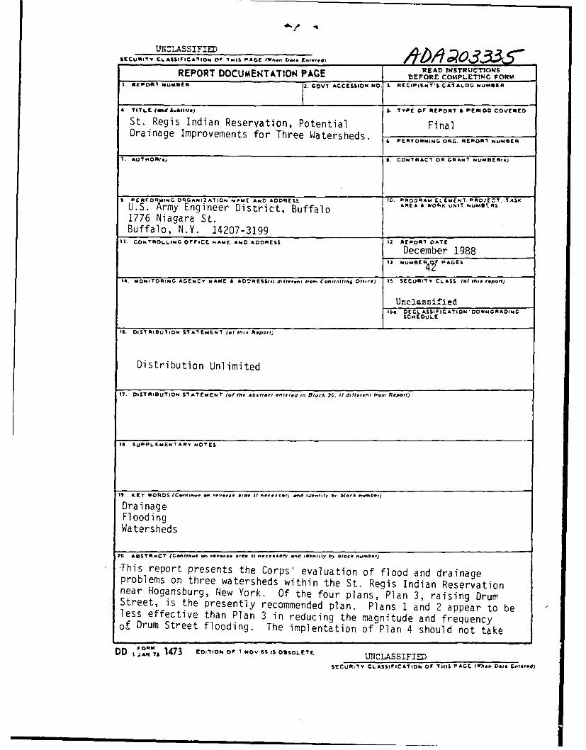
-This report presents the Corps' evaluation of flood and drainageproblems on three watersheds within the St. Regis Indian Reservationnear Hogansburg, New York. Of the four plans, Plan 3, raising DrumStreet, is the presently recommended plan. Plans 1 and 2 appear to beless effective than Plan 3 in reducing the magnitude and frequencyof Drum Street flooding. The implentation of Plan 4 should not take
DD jAN- 1473 EDITION Of I NOV 65 IS OBSOLETE UNCLASSIFIE
SECURITY CLASSIFICATION OF TmIS PAGE (15
.en Dot. Entered)

ABSTRACT
This report was prepared in accordance with the August 27, 1987Memorandum of Agreement between the Buffalo District Corps of Engineers andthe Department of the Interior, Bureau of Indian Affairs, Eastern AreaOffice. It presents the Corps' evaluation of flood and drainage problems on
three watersheds within the St. Regis Indian Reservation near Hogansburg,
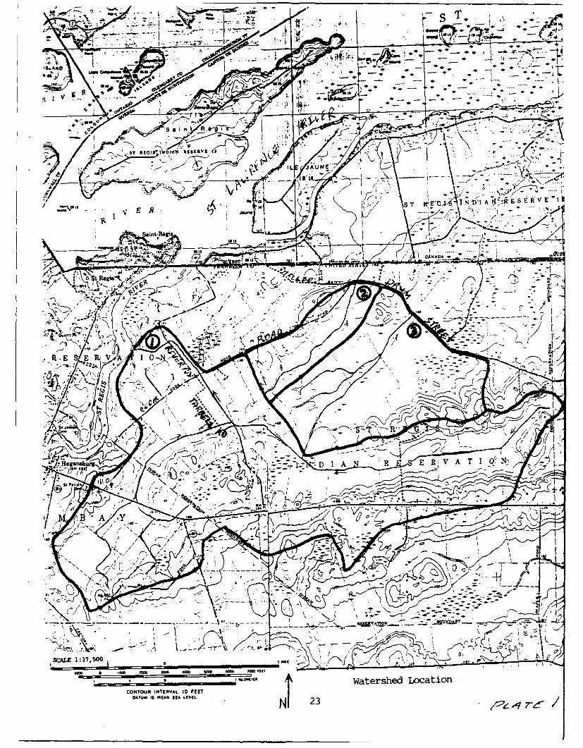
New York. The three watersheds studied are displayed on Plate 1.
Watershed No. I
Watershed No. I has a drainage area of 5.0 mi2 and is bisected by TarbellRoad, Cook Road, and River Road. Tarbell Road is flooded every year due toits low elevation and the inadequate capacity of road culverts and downstreamditches. Along the upstream side of Tarbell Road, the absence of a ditch,
which would direct runoff to existing functional culverts, may alsocontribute to the road inundation. A secondary concern for the Tarbell Road
area is poor agricultural drainage.
Unlike Tarbell Road, Cook Road and River Road rarely experience flooding.Their higher elevation with respect to the surrounding topography results in
few flood problems. The primary need for the area upstream of Cook Road
and River Road is improved agricultural drainage.
Four plans of improvement are presented to reduce the extent or frequency ofTarbell Road inundation. Three of these plans also provide enlarged channels
for improved agricultural drainage.
Plan I proposes enlarged channels and culverts for the main ditches which
cross Tarbell Road, Cook Road, and River Road. The capacity of the enlarged
channels and culverts would be equal to the annual peak discharge which wouldbe equalled or exceeded once in 10 years (10-year peak discharge), and wouldprovide at least 10-year degree of protection for Tarbell Road. Onedisadvantage of this plan is the increased potential for the flooding of alow-lying residence near the mouth of the ditch at the St. Regis River. Thetotal cost of this plan would be approximately $5 million.
Plan 2 also proposes channel and culvert improvements for the main ditches inWatershed No. 1 but not as extensively as Plan 1. Plan 2 improvements would
provide improved agricultural drainage through the construction of 1-year to2-year peak discharge capacity channels. The additional culverts placedunder Tarbell Road, in conjunction with the improved channels, would providebetween 5-year and 10-year degree of protection for Tarbell Road. The costof this plan would be $1.8 million.
Plan 3 is similar to Plan 2 but provides improved agricultural drainage for
the lower portion of the watershed only. Under this plan, the channels wouldbe enlarged to i-year to 2-year capacity from the mouth of the watershed toTarbell Road. Additional culverts are also proposed for Tarbell, Cook, andRiver Roads. This plan would provide 5-year to 10-year degree of protection
for Tarbell Road at a cost of $680,000.
i
Plan 4 provides between 5-year and 10-year degree of protection to TarbellRoad by raising 3,500 feet of the road, 0.5 feet to 2.5 feet above theexisting road surface. Additional culverts would also be installed beneathTarbell Road. The cost of this plan would be $490,000.
Of these 4 plans, Plan 3 is the best plan for-providing both road protectionand agricultural drainage for the present land use patterns. Plans I and 2should not be implemented until existing undeveloped areas are specificallyidentified for residential or agricultural development. Plan 4 presents thebest plan for Tarbell Road protection only.
Watershed No. 2
Watershed No. 2 parallels Cook Road and crosses Drum Street near the Inter-section of Cook Road, Phillils Road, and Drum Street (Spaghetti Corners).Its drainage area is 0.51 mi . The inundation of Drum Street is not aproblem for this watershed. Rather, poor agricultural drainage is theprimary concern.
Two plans are presented for providing improved agricultural drainage forWatershed No. 2. The first plan provides for improved ditch constructionfrom the headwaters of Watershed No. 2 through Canada to the St. LawrenceRiver. Due to the low elevation of Watershed No. 2 with respect to the St.Lawrence River, this gravity drainage plan would likely be ineffective. Itis not recommended for implementation unless additional studies show it tobe effective. The cost of the gravity drainage plan would be $600,000.
Plan 2 for Watershed No. 2 proposes the construction of an enlargedagricultural drainage ditch from the headwaters of the watershed to DrumStreet. At Drum Street, a pump station would be installed to dischargerunoff northward into the existing unimproved ditch. The cost of thisalternative is $500,000. This would be the most effective plan for WatershedNo. 2.
Watershed No. 3
Watershed No. 3 is an 1.58 m12 undeveloped watershed, the runoff of whichcrosses a low-lying portion of Drum Street, 3,800 feet east of SpaghettiCorners. This site at Drum Street is overtopped yearly, making floodprotection the major concern for this watershed. A secondary concern for thewatershed is poor drainage of land considered for future agricultural use.
The cause of Drum Street flooding appears to be high tailwater conditionsdownstream of the road. A less likely cause is inadequate culvert capacity.If inadequate culvert capacity is the cause, it could be alleviated byinstalling an additional culvert for a cost of $21,000 (Plan 1).
iI

If high tailwater is the reason for Drum Street flooding, two options arepresented: construct an improved downstream channel from Drum Street to theSt. Lawrence River (Plan 2) or raise the low portion of Drum Street (Plan 3).The estimated cost of constructing the downstream channel (Plan 2) is$600,000 and in all likelihood would not be effective in reducing thetailwater elevation, due to the relatively high elevation of the St. LawrenceRiver. Conversely, raising Drum Street (Plan 3) would be very effective at acost of approximately $200,000. Whether Drum Street is flooded due toinadequate culvert capacity or high tailwater conditions can be determined bythe St. Regis Mohawk Tribe and other interested parties during the next floodevent using guidance provided in this report.
The final option presented for Watershed No. 3 combines the raising of DrumStreet with the construction of an upstream agricultural drainage ditch andassociated pump station at Drum Street (Plan 4). The estimated cost of thisplan would be approximately $900,000.
Of these 4 plans, Plan 3, raising Drum Street, is the presently recommendedplan. Plans 1 and 2 appear to be less effective than Plan 3 in reducing themagnitude and frequency of Drum Street flooding. The implementation ofPlan 4 should not take place until residential or agricultural development ofWatershed No. 3 requires improved drainage.
Recommendations for Future Studies
It is recommended that the St. Regis Mohawk Tribe pursue additional fundingfor a second stage of study which would provide detailed ditch and roadsurveys, refinement of the hydrologic analysis including determination of theSt. Regis River and St. Lawrence River stage-frequency relationships, and thefinal design dimensions and cost of construction for any selected plans ofimprovement.
ACCtOsion For
I 'IC TABU;hnnno uneed
Justificationj
By
. . .t. i j-"
aii

POTENTIAL DRAINAGE
IMPROVEMENTS FOR THREE WATERSHEDS
Table of Contents
Section Description Page
ABSTRACT ii
1 INTRODUCTION 1
2 TARBELL ROAD-COOK ROAD-RIVER ROADWATERSHED (WATERSHED NO. 1) 2
A. Watershed Characteristics 2
B. Flood History and Study Focus 3C. Hydrologic Analysis 3D. Plans of Improvement 3E. Recommendations 13
3 COOK ROAD-PHILLIPS ROAD-DRUM STREETWATERSHED (WATERSHED NO. 2) 14
A. Watershed Description 14B. Flood History and Study Focus 14
C. Hydrologic Analysis 14D. Plans of Improvement 14E. Recommendations 16
4 DRUM STREET WATERSHED (WATERSHED NO. 3) 17A. Watershed Description 17B. Flood History and Study Focus 17
C. Hydrologic Analysis 17D. Plans of Improvement 17E. Recommendations 22
5 RECOMMENDATIONS FOR FUTURE STUDIES 22
Tables
Number Title
1 10-Year Peak Discharges for Watershed No. 1, Plan 1 3
2 Costs for Watershed No. 1, Plan 1 53 Design Discharges for Watershed No. 1, Plan 2 7
4 Costs for Watershed No. 1, Plan 2 95 Costs for Watershed No. 1, Plan 3 11
6 Costs for Watershed No. 1, Plan 4 13
7 Costs for Watershed No. 2, Plan 1 15
8 Costs for Watershed No. 2, Plan 2 16
iv

Table of Contents (continued)
Tables (continued)
Number Title Page
9 Costs for Watershed No. 3, Plan 1 18
10 Costs for Watershed No. 3, Plan 2 19
ii Costs for Watershed No. 3, Plan 3 2012 Costs for Watershed No. 3, Plan 4 21
Plates
Number Title Page
I Watershed Locations 23
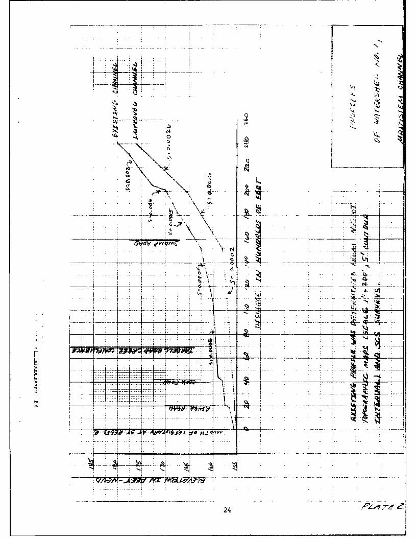
2 Profiles of Watershed No. 1,Mainstem Channel 24
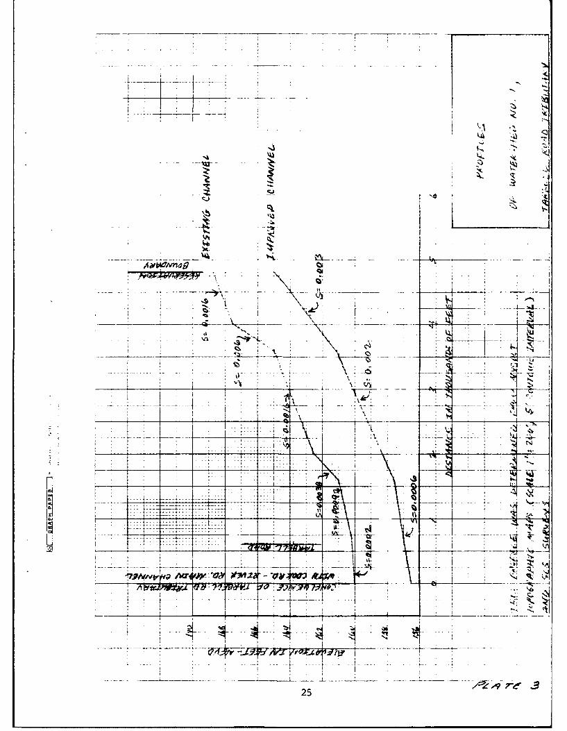
3 Profiles of Watershed No. I,Tarbell Road Tributary 25
4 Watershed No. 1, Plan 1 Improvements 265 Watershed No. 1, Plan 2 Improvements 27
6 Watershed No. 1, Plan 3 Improvements 28
7 Watershed No. 1, Plan 4 Improvements 29
8 Profile of Tarbell Road 30
9 Watershed No. 2, Plan 1 Improvements 31
10 Watershed No. 2, Plan 2 Improvements 32
11 Watershed No. 3, Plan 1 Improvements 33
12 Watershed No. 3, Plan 2 Improvements 34
13 Profile of Drum Street in Vicinityof Watershed No. 3 35
14 Watershed No. 3, Plan 3 Improvements 36
15 Watershed No. 3, Plan 4 Improvements 37
v

I. INTRODUCTION
This report presents the Buffalo District Corps of Engineers' evaluationof flood and drainage problems along Tarbell Road, Cook Road, River Road, and
Drum Street on the St. Regis Indian Reservation near Hogansburg, New York.The present frequency of flooding of these roads is discussed in this reportalong with alternatives for reducing the frequency of flooding and improving
agricultural drainage. The costs of each alternative and its effectivenessare also presented.
2. TARBELL ROAD - COOK ROAD - RIVER ROAD WATERSHED (WATERSHED NO. 1)
A. Watershed Characteristics
The Tarbell Road - Cook Road - River Road (TCR) watershed (Watershed
No. 1) is shown in Plate 1. The upstream end of the watershed is locatednear the intersection of McElwain Road and Drum Street. The downstream end
of the watershed is in the vicinity of Cook Road and River Road. The entirewatershed has a drainage area of 5.0 mi 2 and includes a 1.5 square mile
tributary located west of Tarbell Road. The watershed empties into the St.
Regis River, 2,000 feet downstream of River Road.
Watershed No. 1 exhibits diversity in topography, soil types, and land
use. With respect to topography, the perimeter of the watershed is hillywhile the areas adjoining the creek are very flat and poorly drained. The
highest point In the watershed has an elevation of approximately 230 (1) andis located near Route 37 and Beaver Meadow Road. The elevation at the mouth
of the watershed is 155.
The average slope of the existing main channel of Watershed No. I varies
from 0.006 ft/ft in the upstream reach to 0.0002 ft/ft in the lower portionof the watershed, as shown on Plate 2. A similar channel profile for theTarbell Road tributary is presented in Plate 3.
Soil types within the watershed are also varied. The hilly regions along
the perimeter of the watershed exhibit moderately well drained soils
classified as type B by the Soil Conservation Service (SCS). Soils locatednear the base of the hills and along the floodplain of the creek are more
poorly drained, fine textured soils classified as types C and D by the SCS.Land use in the watershed consists primarily of woods and brush although somefarming occurs in the lower portion of the watershed near Cook Road and River
Road.
(1) All elevations in this report are in feet above mean sea level, National
Geodetic Vertical Datum (NGVD).
1

B. Flood History and Study Focus
According to Mr. Wes Laughing, Planner for the St. Regis Mohawk Tribe,Tarbell Road is flooded annually while Cook Road and River Road rarely, if
ever, experience flooding. His observations are supported by the hydrologicmodelling performed for this report. The frequent flooding of Tarbell Roadis due to inadequate road ditch, stream channel and culvert capacity alongTarbell Road. In particular, an existing culvert located 1,200 feet north ofthe main Tarbell Road stream crossing is damaged and non-functional. Inaddition, along the west side of Tarbell Road, the absence of a ditch, whichwould lead surface runoff to functioning culverts, could be a contributingfactor to the frequent flooding of Tarbell Road. Therefore, the types ofimprovements proposed for the Tarbell Road area of Watershed No. I wouldprovide flood protection and in many cases also provide improved landdrainage.
Unlike Tarbell Road, the Cook Road and River Road crossings of themain channel are much higher than the surrounding watershed. Cook Road Inparticular provides significant storage of flood waters without overtoppingand functions as a dam in storing water and releasing it slowly downstream.However, the temporary storage of this water hinders the efficientagricultural use of this land. Therefore, the plans of improvement for themain channel of Watershed No. 1 were chosen to provide improved landdrainage.
C. Hydrologic Analysis
Several methods were used t9 design drainage improvements for WatershedNo. 1. The SCS drainage guide 2) v design discharges for
agricultural drainage while TR-20 was used to compute discharges ofspecific return interval such as the 10-year peak discharge. Manning'sequation was then used to determine the improved channel 7haracteristlcs forthe design discharge. The 1987 mean water level (el. 155 ft. NGVD) for theSt. Lawrence River between Cornwall, Ontario and Summerstown, Ontario wasused to represent the St. Regis River at the mouth of Watershed No. I and wasused in designing the plans of improvement.
D. Plans of Improvement
Four options are presented for reducing the frequency of Tarbell Roadinundation. The first three plans presented also provide for improvedagricultural drainage in addition to Tarbell Road flood reduction.
(2) USDA Soil Conservation Service. September 1987. Drainage Guide for NewYork State. Syracuse, New York. 80 pp.
(3) USDA Soil Conservation Service. May 1982. Technical Release Number 20(TR-20), Project Formulation-Hydrology. Lanham, Maryland.
2

I. Plan I
Plan I would provide 10-year peak discharge channel and culvert capacity
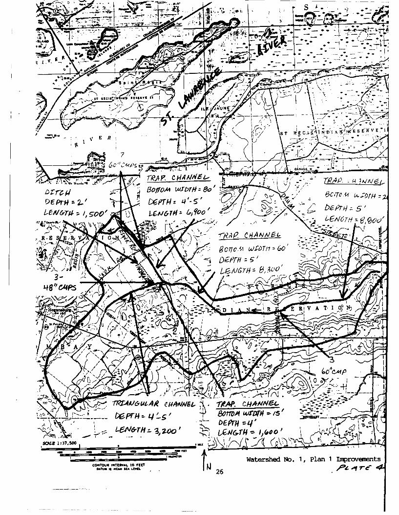
for both the main channel and the Tarbell Road tributary. The 10-year designdischarges for these streams, determined by TR-20, are displayed in Table 1.The watershed improvements proposed by Plan I are shown on Plate 4.
Table 1. 10-Year Peak Discharges for Watershed No. 1, Plan 1
Location
Drainag_ Area Dischar eTarbell Road Tributary (mi2) (cfs
1. Tarbell Road 1.5 135
Main Channel
1. Station 152+00 to 240+00 1.0 320
2. Station 69+00 to 152+00 2.7 475
3. Station 0+00 to 69+00 5.0 630
a. Tarbell Road Tributary
With respect to the Tarbell Road tributary, e 10-year capacity channel
would extend from the mouth of the tributary upstream to the reservationboundary, a distance of 4,800 feet. TR-20 analysis of this tributary showsthat the 10-year peak discharge under improved channel conditions is 135 cfs.
The improved channel for the lower 1,600 feet of the Tarbell Road tributarywould bave a bottom width of 15 feet, depth of 4 feet, and slope of 0.0016
ft/ft 4). For the remaining 3,200 feet of the Tarbell Road tributary, theImproved channel would be triangular in cross-section, 4-5 feet deep, and be
sloped 0.002-0.003 ft/ft. The profile of the improved channel Is displayedon Plate 3.
In addition to the enlarged channel, three 48-inch corrugated metal
pipes (cmp) would be placed beneath Tarbell Road to pass 135 cfs with aheadwater elevation of 161.5, 2.3 feet below the top of the road. Atailwater elevation of 161.0 was used in sizing the culverts since 161.0 isthe 10-year peak elevation of the TCR main channel under Plan 1.
The final Plan 1 improvement to the Tarbell Road tributary would be a
1,500-foot long ditch which would be constructed along the west (upstream)side of Tarbell Road. The ditch would be triangular in cross-section,
2 feet deep, and exhibit a slope of 0.001 ft/ft. The mouth of the ditch
should be connected to the tributary channel on the upstream side of Tarbell
(4) All improved channels proposed in this report are designed with 2H:IVsideslopes.
3
Road. This ditch, along with the other Plan I improvements, will providemore than 10-year degree of protection for Tarbell Road.
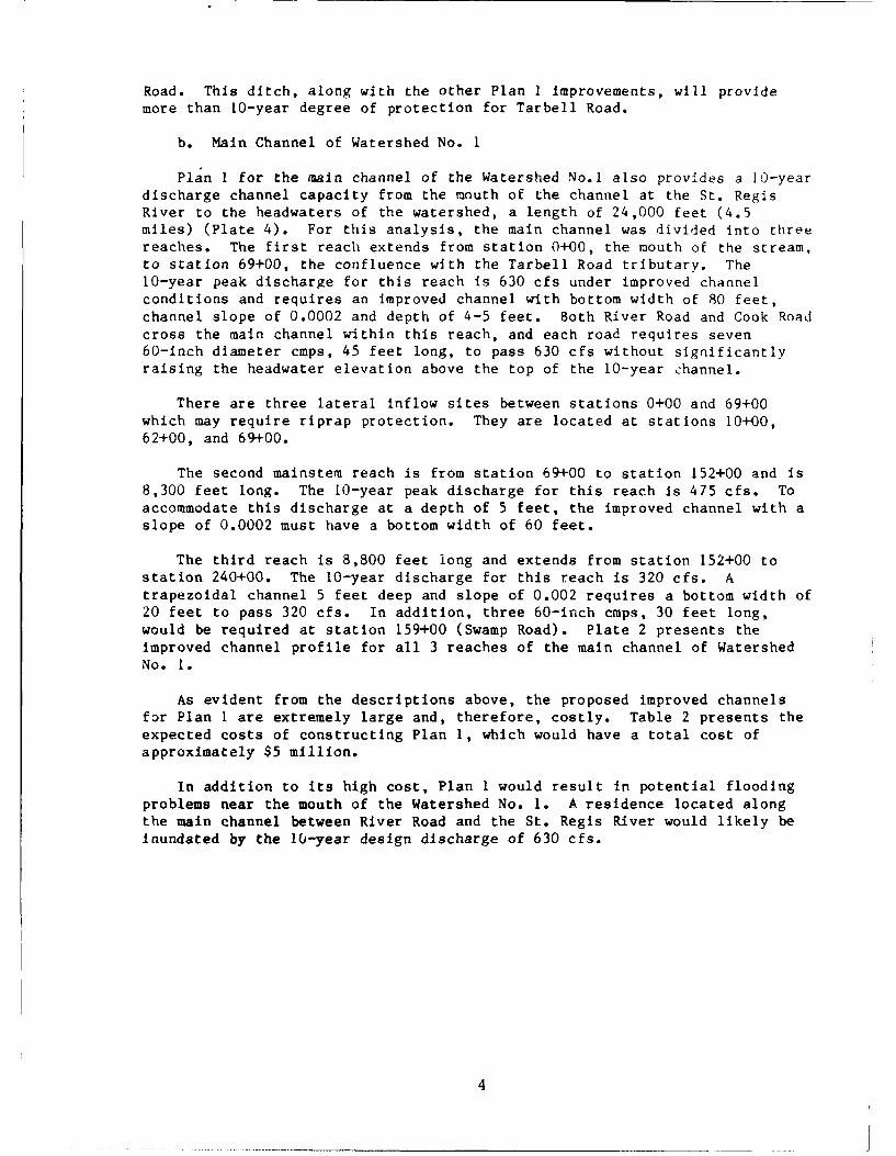
b. Main Channel of Watershed No. I
Plan I for the main channel of the Watershed No.1 also provides a 10-yeardischarge channel capacity from the mouth of the channel at the St. RegisRiver to the headwaters of the watershed, a length of 24,000 feet (4.5miles) (Plate 4). For this analysis, the main channel was divided into threereaches. The first reach extends from station 0+00, the mouth of the stream,to station 69+00, the confluence with the Tarbell Road tributary. The10-year peak discharge for this reach is 630 cfs under improved channelconditions and requires an improved channel with bottom width of 80 feet,channel slope of 0.0002 and depth of 4-5 feet. Both River Road and Cook Roadcross the main channel within this reach, and each road requires seven60-inch diameter cmps, 45 feet long, to pass 630 cfs without significantlyraising the headwater elevation above the top of the 10-year channel.
There are three lateral inflow sites between stations 0+00 and 69+00which may require riprap protection. They are located at stations 10+00,62+00, and 69+00.
The second mainstem reach is from station 69+00 to station 152+00 and is8,300 feet long. The 10-year peak discharge for this reach is 475 cfs. Toaccommodate this discharge at a depth of 5 feet, the improved channel with aslope of 0.0002 must have a bottom width of 60 feet.
The third reach is 8,800 feet long and extends from station 152+00 tostation 240+00. The 10-year discharge for this reach is 320 cfs. Atrapezoidal channel 5 feet deep and slope of 0.002 requires a bottom width of20 feet to pass 320 cfs. In addition, three 60-inch cmps, 30 feet long,would be required at station 159+00 (Swamp Road). Plate 2 presents theimproved channel profile for all 3 reaches of the main channel of WatershedNo. 1.
As evident from the descriptions above, the proposed improved channelsfor Plan I are extremely large and, therefore, costly. Table 2 presents theexpected costs of constructing Plan 1, which would have a total cost ofapproximately $5 million.
In addition to its high cost, Plan I would result in potential floodingproblems near the mouth of the Watershed No. 1. A residence located alongthe main channel between River Road and the St. Regis River would likely beinundated by the l0-year design discharge of 630 cfs.
4

Modelling of the existing watershed shows that the present 2.5 foot by5.0 foot box culvert under Cook Road normally restricts streamflow, thuscausing Cook Road to act as a dam by storing water upstream and therebyreducing downstream flows. Under Plan 1, this flow restriction would beremoved. Due to the high cost and potential downstream flood problemsassociated with Plan 1, an alternate drainage plan is presented next.
Table 2. Costs for Watershed No. 1, Plan I
Main Channel
Station 0+00 to 69+00
UnitEstimated Price Cost
Item Description Quantity Unit ($) ($1,000)
60-inch cmp 630 lin. ft. 155 97.6Bituminous roadway w/subgrade 220 lin. ft. 85 18.7Channel excavation 153,300 yd3 10 1,533.018-inch riprap w/6 in. bedding 208 yd2 35 7.3Total contractor's earnings 1,656.6
Station 69+00 to 152+00
UnitEstimated Price Cost
Item Description Ouantity Unit (M) ($1,000)
Clear and grub (medium) 22.9 ac 6,000 137.4Channel excavation 91,600 yd3 10 916.0Total contractor's earnings 1,053.4
Station 152+00 to 240+00
UnitEstimated Price Cost
Item Description Quantity Unit ($) ($1,000)
60-inch cmp 90 lin. ft. 155 14.0Clear and grub (medium) 16.2 ac 6,000 97.2Channel excavation 37,800 yd3 10 378.0Total contractor's earnings 489.2
5
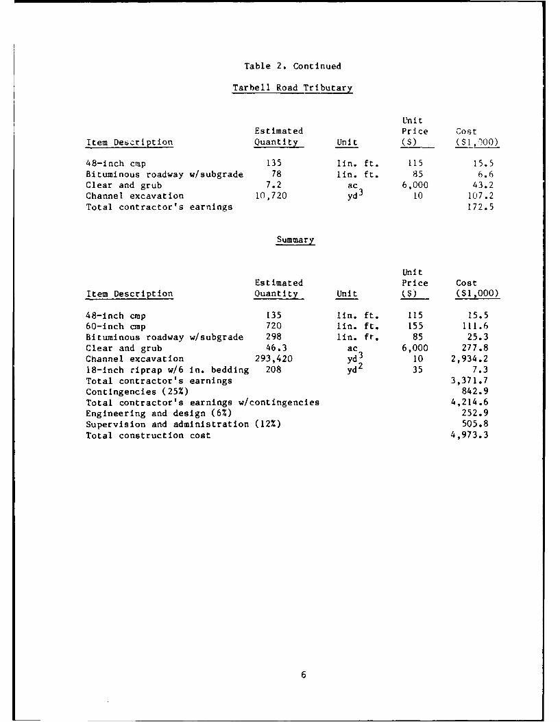
Table 2. Continued
Tarbell Road Tributary
UnitEstimated Price Cost
Item Deszription Quantity Unit ($) ($1,00)
48-inch cmp 135 lin. ft. 115 15.5Bituminous roadway w/subgrade 78 lin. ft. 85 6.6Clear and grub 7.2 ac 6,000 43.2Channel excavation 10,720 yd3 10 107.2Total contractor's earnings 172.5
Summary
UnitEstimated Price Cost
Item Description Ouantity Unit ($) ($1,000)
48-inch cmp 135 lin. ft. 115 15.560-inch cmp 720 lin. ft. 155 111.6Bituminous roadway w/subgrade 298 lUn. ft. 85 25.3Clear and grub 46.3 ac 6,000 277.8Channel excavation 293,420 yd3 10 2,934.218-inch riprap w/6 in. bedding 208 yd2 35 7.3Total contractor's earnings 3,371.7Contingencies (25%) 842.9Total contractor's earnings w/contingencies 4,214.6Engineering and design (6%) 252.9
Supervision and administration (12%) 505.8Total construction cost 4,973.3
6

2. Plan 2
Plan 2 for Watershed No. 1 is based on the SCS Drainage Guide. Thisguide does not base channel and culvert improvements on a particulardischarge frequency or return period but rather on land use. For a givenland use and drainage area, the guide provides the appropriate channelcapacity to improve land drainage while still allowing overbank floodingduring moderate and large runoff events.
Table 3 presents the drainage areas and design discharges for variouslocations in the watershed. Cropland is the land use chosen for this design.
Table 3. Design Discharges for Watershed No. 1, Plan 2
Location Drainage Area Discharge
Tarbell Road Tributary (mi (cfs)
1. Tarbell Road 1.5 55
Main Channel
1. Station 152+00 to 240+00 1.0 40
2. Station 69+00 to 152+00 2.7 85
3. Station 0+00 to 69+00 5.0 140
a. Tarbell Road Tributary
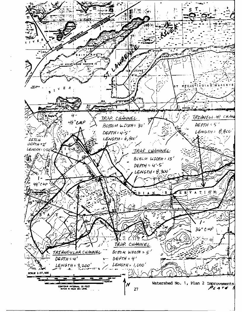
To provide the 55 cfs design discharge at Tarbell Road, a 4-foot deeptrapezoidal channel with 5-foot bottom width is proposed. This improvedchannel would extend from the mouth of the Tarbell Road tributary to alocatit-n 1,000 feet upstream of Tarbell Road (total length: 1,600 feet)(Plate 5). From 1,000 feet upstream of Tarbell Road to the reservationboundary, a total distance of 3,200 feet, the improved channel would betriangular with a depth of 4 feet. The profile of this improved channel isthe same as the one presented for Plan 1 (Plate 3).
An additional culvert is proposed for the Tarbell Road tributary. Asingle 48-inch cmp with invert at elevation 157.0 would be placed next tothe two existing 30-1nch cmps.
In addition to the above channel and culvert, a 1,500-foot long ditchwould be constructed along the west side of Tarbell Road. The dimensions ofthis ditch are the same as those presented previously in Plan 1. Theseimprovements to the Tarbell Road tributary, along with the Plan 2improvements to the main channel, would provide between 5-year and 10-yeardegree of protection to Tarbell Road.
7
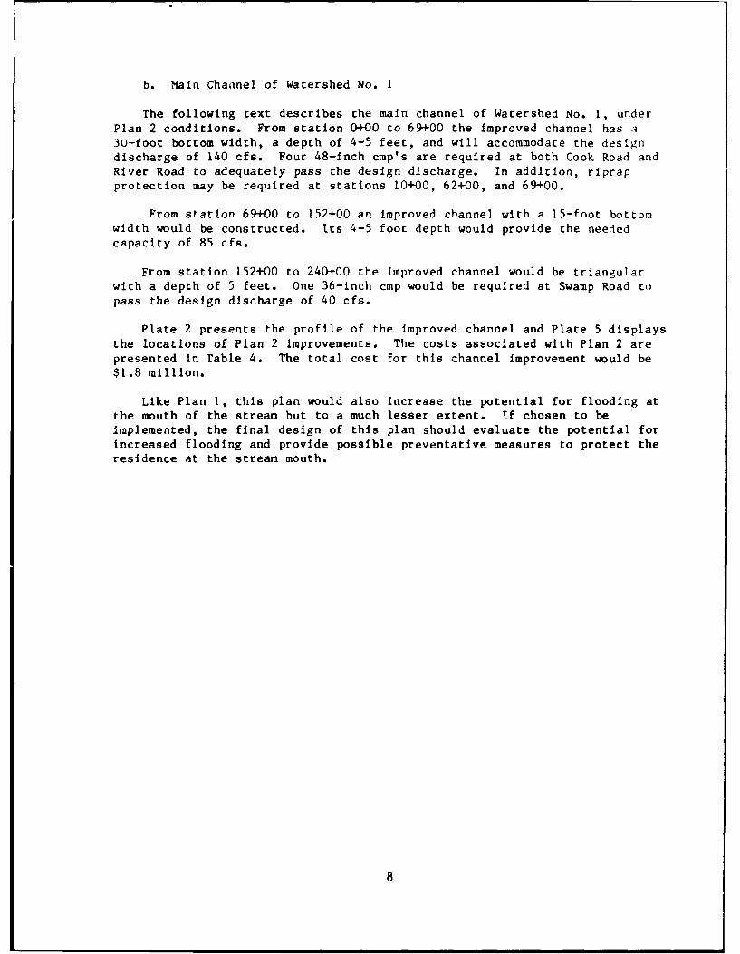
b. Main Chaanel of Watershed No. 1
The following text describes the main channel of Watershed No. 1, underPlan 2 conditions. From station 0+00 to 69+00 the improved channel has a30-foot bottom width, a depth of 4-5 feet, and will accommodate the designdischarge of 140 cfs. Four 48-inch cmp's are required at both Cook. Road andRiver Road to adequately pass the design discharge. In addition, riprapprotection may be required at stations 10+00, 62+00, and 69+00.
From station 69+00 to 152+00 an improved channel with a 15-foot bottomwidth would be constructed. Its 4-5 foot depth would provide the neededcapacity of 85 cfs.
From station 152+00 to 240+00 the improved channel would be triangularwith a depth of 5 feet. One 36-inch cmp would be required at Swamp Road topass the design discharge of 40 cfs.
Plate 2 presents the profile of the improved channel and Plate 5 displaysthe locations of Plan 2 improvements. The costs associated with Plan 2 arepresented in Table 4. The total cost for this channel improvement would be$1.8 million.
Like Plan 1, this plan would also increase the potential for flooding atthe mouth of the stream but to a much lesser extent. If chosen to beimplemented, the final design of this plan should evaluate the potential forincreased flooding and provide possible preventative measures to protect theresidence at the stream mouth.

Table 4. Costs for Watershcd No. i, Plan 2
Main Channel
Station 0+00 to 69+00Unit
Estimated Price Cost
Item Description Ouantity Unit (M) ($1,000)
48-inch cmp 360 lin. ft. 115 41.4
Bituminous roadway w/subgrade 180 lin. ft. 85 15.3
Channel excavation 37,100 yd3 10 371.018-inch riprap w/6 in. bedding 208 yd2 35 7.3Total contractor's earnings 435.0
Station 69+00 to 152+00
UnitEstimated Price Cost
Item Description Quantity Unit (M) ($1,000)
Clear and grub (medium) 14.3 ac 6,000 85.8
Channel excavation 28,000 yd3 10 280.0
Total contractor's earnings 365.8
Station 152+00 to 240+00
UnitEstimated Price Cost
Item Description Quantity Unit ($) ($1,000)
36-inch cmp 30 lin. ft. 75 2.3
Clear and grub (medium) 12.1 ac 6,000 72.6
Channel excavation 18,900 yd3 10 189.0
Total contractor's earnings 263.9
9
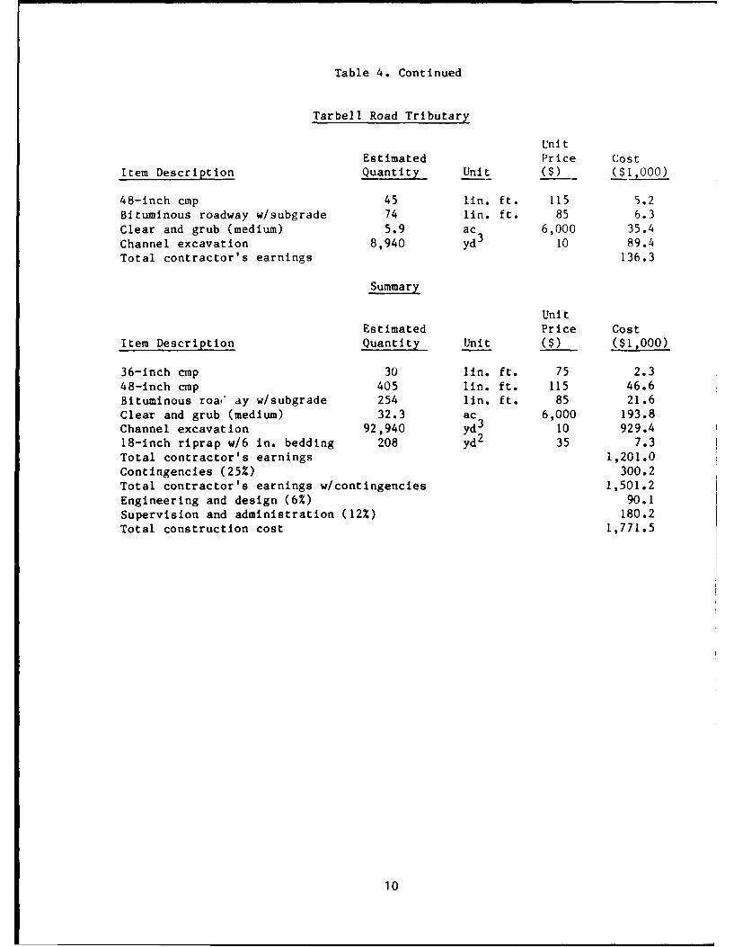
Table 4. Continued
Tarbell Road Tributary
UnitEstimated Price Cost
Item Description Quantity Unit C) ($,000)
48-inch cmp 45 lin. ft. 115 5.2Bituminous roadway w/subgrade 74 fin. ft. 85 6.3Clear and grub (medium) 5.9 ac 6,000 35.4
Channel excavation 8,940 yd3 10 89.4Total contractor's earnings 136.3
Summary
Uni tEstimated Price Cost
Item Description Quantity Unit ($) ($I,000)
36-inch cmp 30 lIn. ft. 75 2.348-inch cmp 405 lin. ft. 115 46.6Bituminous roa,* ay w/subgrade 254 lin. ft. 85 21.6
Clear and grub (medium) 32.3 ac 6,000 193.8Channel excavation 92,940 yd2 10 929.418-inch riprap w/6 in. bedding 208 yd 35 7.3Total contractor's earnings 1,201.0
Contingencies (25%) 300.2Total contractor's earnings w/contingencies 1,501.2Engineering and design (6%) 90.1Supervision and administration (12%) 180.2Total construction cost 1,771.5
10

3. Plan 3
Plan 3 would provide 5-year to 10-year degree of protection for TarbellRoad and improved drainage for the downstream agricultural portion ofWatershed No. I by proposing a scaled-down version of Plan 2. Plan 3proposes a 4-foot deep, 5-foot bottom width trapezoidal channel for theTarbell Road tributary, which would extend from Tarbell Road downstream tothe main channel of Watershed No. 1, a distance of 600 feet (Plate 6). A48-inch cmp would be installed alongside the existing 30-inch cmps at TarbellRoad. A 1,500-foot long, 2-foot deep ditch would be constructed along theupstream side of Tarbell Road to direct surface runoff to the main culvertsbeneath the road.
The main channel ot the watershed would be enlarged to a 4-foot deep,30-foot bottom width trapezoidal channel which would extend from the St.Regis River (Station 0+00) to the confluence with the Tarbell Road tributary(Station 69+00), a distance of 6,900 feet. In addition, four 48-inch cmpswould be installed at Cook Road and River Road and riprap would be placed atStations 10+00, 62+00, and 69+00. The total cost of this plan would be$680,000 as presented in Table 5.
Table 5. Costs for Watershed No. 1, Plan 3
Main Channel
Station 0+00 to 69+00
UnitEstimated Price Cost
Item Description Quantity Unit ($) ($1,000)
48-inch cmp 360 lin. ft. 115 41.4
Bituminous roadway w/subgrade 180 lin. ft. 85 15.3
Channel excavation 37,100 yd3 10 371.0
18-inch riprap w/6 in. bedding 208 yd2 35 7.3
Total contractor's earnings 435.0
Tarbell Road Tributary
UnitEstimated Price Cost
Item Description Quantity Unit ($) ($1,000)
48-inch cmp 45 lin. ft. 115 5.2
Bituminous roadway w/subgrade 74 lin. ft. 85 6.3
Channel excavation 1,600 yd3 10 16.0
Total contractor's earnings 27.5
11

Table 5. Continued
Summary
Uni tEstimated Price Cost
Item Description Quantity Unit ($) ($1,000)
48-inch cmp 405 lin. ft. 115 46.6Bituminous roadway w/subgrade 254 lin. ft. 85 21.6
Channel excavation 38,700 yd3 10 387.018-inch riprap w/6 in. bedding 208 yd2 35 7.3Total contractor's earnings 462.5Contingencies (25%) 115.6Total contractor's earnings w/contingencies 578.1Engineering and design (6%) 34.7Supervision and administration (12%) 69.4Total construction cost 682.2
12
4. Plan 4
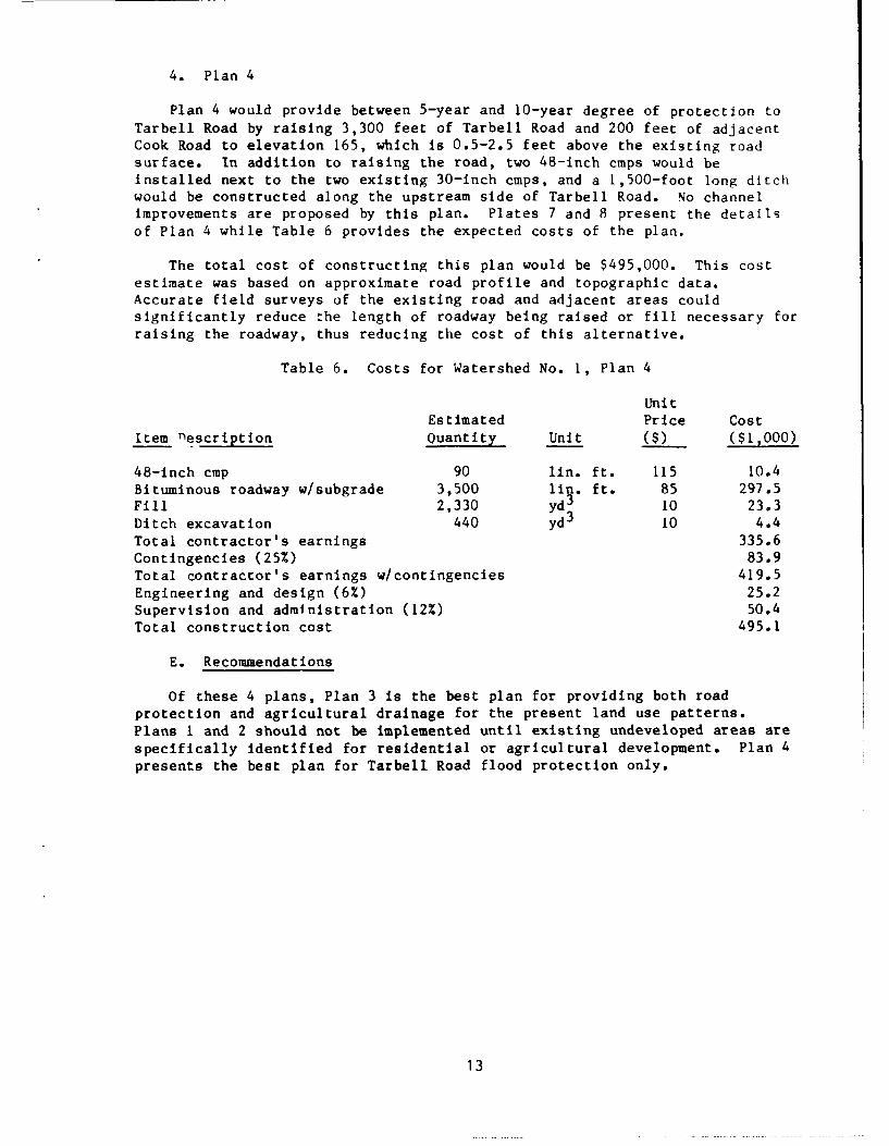
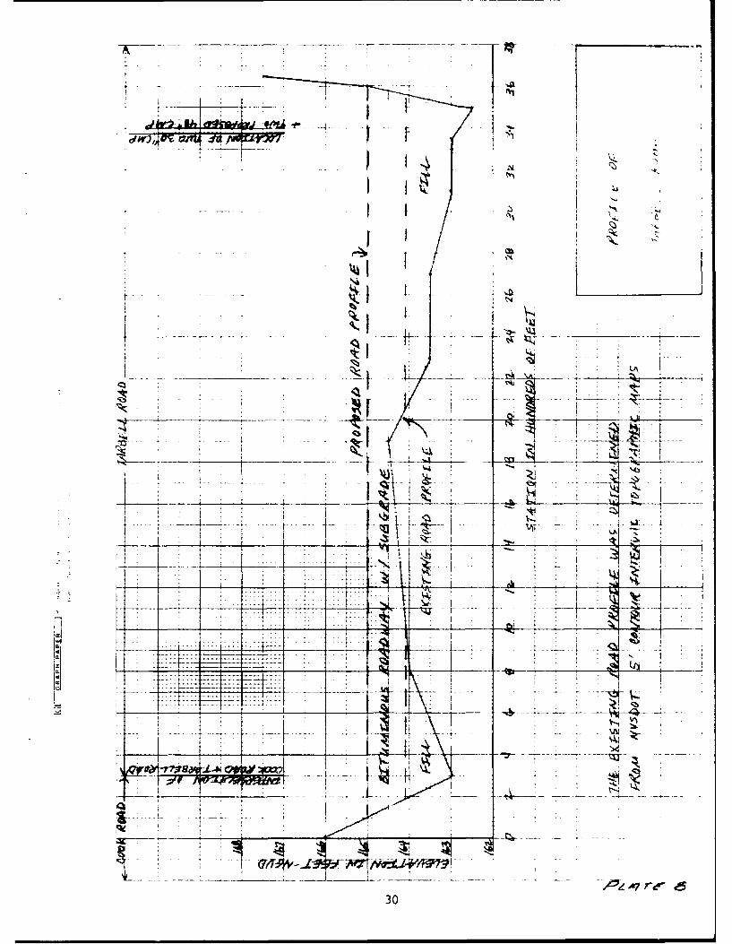
Plan 4 would provide between 5-year and 10-year degree of protection toTarbell Road by raising 3,300 feet of Tarbell Road and 200 feet of adjacentCook Road to elevation 165, which is 0.5-2.5 feet above the existing roadsurface. In addition to raising the road, two 48-inch cmps would beinstalled next to the two existing 30-inch cmps, and a 1,500-foot long ditchwould be constructed along the upstream side of Tarbell Road. No channelimprovements are proposed by this plan. Plates 7 and 8 present the detailsof Plan 4 while Table 6 provides the expected costs of the plan.
The total cost of constructing this plan would be $495,000. This costestimate was based on approximate road profile and topographic data.Accurate field surveys of the existing road and adjacent areas couldsignificantly reduce the length of roadway being raised or fill necessary forraising the roadway, thus reducing the cost of this alternative.
Table 6. Costs for Watershed No. 1, Plan 4
UnitEstimated Price Cost
Item nescription Ouantity Unit ($) ($1P000)
48-inch cmp 90 lin. ft. 115 10.4Bituminous roadway w/subgrade 3,500 lin. ft. 85 297.5Fill 2,330 yd3 10 23.3Ditch excavation 440 yd3 10 4.4Total contractor's earnings 335.6Contingencies (25%) 83.9Total contractor's earnings w/contingencies 419.5Engineering and design (6%) 25.2Supervision and administration (12%) 50.4Total construction cost 495.1
E. Recommendations
Of these 4 plans, Plan 3 is the best plan for providing both roadprotection and agricultural drainage for the present land use patterns.Plans I and 2 should not be implemented until existing undeveloped areas arespecifically identified for residential or agricultural development. Plan 4presents the best plan for Tarbell Road flood protection only.
13

3. COOK ROAD - PHILLIPS ROAD - DRUM STREET WATERSHED (WATERSHED NO. 2)
A. Watershed Description
Watershed No. 2 is shown on Plate 1. A small, unmaintained ditch, which
extendd from the headwaters of the watershed to Drum Street, is 7,200 feetlong. Downstream from Drum Street, the ditch extends 1,000 feet to theU.S.-Canada border. In Canada, the ditch is intermittent from the border tothe ditch's confluence with Bittern Creek, a distance of 9,400 feet. The
ditch's confluence with Bittern Creek is 4,100 feet upstream of the mouth of
Bittern Creek and the St. Lawrence River.
The drainage area of Watershed No. 2 is 0.51 mi 2 to Drum Street. The
primary land use of this watershed is crop production associated with dairy
farming. The watershed is very flat and requires improved drainage toprovide maximum crop production.
B. Flood History and Study Focus
The main channel (ditch) for Watershed No. 2 rarely floods Drum Street,
according to Mr. Wes Laughing. The primary need for this watershed is
improved drainage for crop production.
C. Hydrologic Analysis
The SCS Drainage Guide was used to determine the design discharge for themain ditch of the watershed under improved conditions. For a drainage area
of 0.51 mi2 . the design discharge for cropland is 25 cfs. Following thecalculation of the design discharge, Manning's equation was used to size theditch. In addition to providing the design discharge, the drainage guide
also provided information concerning pump station design, an option
considered for this watershed.
D. Plans of Improvement
Two plans for improving land drainage were considered. Plan 1
investigated the potential for improved gravity ditch flow from theheadwaters of the watershed to the St. Lawrence River. Plan 2 combines
improved gravity flow and a pump station to facilitate cropland drainage.
The following sections describe the plans in detail.
1. Plan 1
Drainage improvements based on gravity flow through enlarged ditches andculverts are generally less costly and therefore preferable over theinstallation of pump stations. This plan considered gravity flow
improvements for Watershed No. 2 and the downstream Canadian reach from the
U.S.-Canada border to Bittern Creek and the St. Lawrence River. The Canadianportion of this stream was included in the plan to insure that flow from the
U.S. portion would not be hindered by downstream obstructions. However,
based on the existing ditch elevation and the downstream water level of theSt. Lawrence River, this plan may still be ineffective.
14
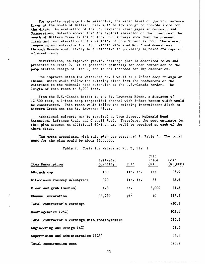
For gravity drainage to be effective, the water level of the St. LawrenceRiver at the mouth of Bittern Creek must be low enough to provide slope forthe ditch. An evaluation of the St. Lawrence River gages at Cornwall andSummerstown, Ontario showed that the typical elevation of the river near themouth of Bittern Creek is 154 to 155. SCS surveys show that the presentditch and land elevation in the vicinity of Drum Street is 155. Therefore,deepening and enlarging the ditch within Watershed No. 2 and downstreamthrough Canada would likely be ineffective in providing improved drainage ofadjacent land.
Nevertheless, an improved gravity drainage olan is described below andpresented in Plate 9. It is presented primarily for cost comparison to thepump station design of Plan 2, and is not intended for implementation.
The improved ditch for Watershed No. 2 would be a 4-foot deep triangularchannel which would follow the existing ditch from the headwaters of thewatershed to the McDonald Road Extension at the U.S.-Canada border. Thelength of this reach is 8,200 feet.
From the U.S.-Canada border to the St. Lawrence River, a distance of12,500 feet, a 4-foot deep trapezoidal channel with 5-foot bottom width wouldbe constructed. This reach would follow the existing intermittent ditch toBittern Creek and the St. Lawrence River.
Additional culverts may be required at Drum Street, McDonald RoadExtension, LaFrance Road, and Chenail Road. Therefore, the cost estimate forthis plan assumes an additional 60-inch cmp would be required at each of theabove sites.
The costs associated with this plan are presented in Table 7. The totalcost for the plan would be about $600,000.
Table 7. Costs for Watershed No. 2, Plan 1
Unit
Estimated Price CostItem Description Ouantity Unit ($) ($1,000)
60-inch cmp 180 lin. ft. 155 27.9
Bituminous roadway w/subgrade 340 lin. ft. 85 28.9
Clear and grub (medium) 4.3 ac. 6,000 25.8
Channel excavation 33,790 yd3 10 337.9
Total contractor's earnings 420.5
Contingencies (25%) 105.1
Total contractor's earnings with contingencies 525.6
Engineering and design (6%) 31.5
Supervision and administration (12%) 63.1
Total construction cost 620.2
15

2. Plan 2
This plan would enlarge the existing shallow ditch to a 4-foot deeptriangular ditch from the headwaters of the watershed to Drum Street, adistance of 7,200 feet (Plate 10). The 4-foot depth is the minimum depthrequired for tile drainage of adjacent land. The 4-foot depth also providesthe 25 cfs design discharge capacity as determined from the SCS drainageguide.
In addition to the improved ditch, a pump station would be constructed onthe upstream side of Drum Street. The pump station would have 2 or 3 pumpswith a total capacity of 25 cfs (11,000 gpm). Based on information suppliedby Mr. Walt Grajko, SCS, Syracuse, New York, the pump station cost isestimated at $250,000 and would include an Improved gravity flow outlet withflap gates at Drum Street. The total cost of this alternative isapproximately $500,000 as displayed in Table 8.
This alternative would increase the frequency with which McDonald RoadExtension, 1,000 feet downstream of Drum Street, is flooded. However, sincethere are alternative routes to McDonald Road Extension and since theMcDonald Road Extension is presently low-lying and likely flooded each year,no raising of the McDonald Road Extension is recommended. Raising theMcDonald Road Extension by 6 feet, to the height of adjacent roadways, wouldadd $300,000 to $400,000 to the cost of Plan 2.
Table 8. Costs for Watershed No. 2, Plan 2
UnitEstimated Price Cost
Item Description Quantity Unit ($) ($1PO)
Channel excavation 8,530 yd3 10 85.3
Pump station, 11,000 gpm capacity 250.0
Total contractor's earnings 335.3
Contingencies (25%) 83.8
Total contractor's earnings w/contingencies 419.1
Engineering and design (6%) 25.1
Supervision and administration (12%) 50.3
Total construction cost 494.5
E. Recommendation
Plan 2 is recommended as the most effective plan for providingimproved agricultural drainage for Watershed No. 2.
16

4. DRLM STREET WATERSHED (WATERSHED NO. 3)
A. Watershed Description
Watershed No. 3 is located adjacent to and eastward of Watershed No. 2
(Plate 1). The outflow from Watershed No. 3 crosses Drum Streetapproximately 3,800 feet east of the intersection of Cook Road, PhillipsRoad, and Drum Street. The intersection of these 3 roads is known locally asSpaghetti Corners. The drainage area of Watershed No. 3 upstream of DrumStreet is 1.58 m1 2 .
The central portion of the watershed is flat, low-lying, swampy andbrush-covered. There is no crop production at present in this watershed.Drainage of runoff from the watershed is hindered by the lack of slope fromDrum Street to the St. Lawrence River. Maps of this area show no definedchannel downstream of the watershed outlet at Drum Street. Rather, thewatershed drains to a swamp on the north side of Drum Street which extendsapproxiamtely 9,400 feet northward to Bittern Creek.
B. Flood History and Study Focus
Mr. Wes Laughing reports that Drum Street is inundated each year in thevicinity of Watershed No. 3. Therefore, the primary concern for thiswatershed is the reduction of Drum Street inundation.
In addition to road inundation, poor drainage causes Watershed No. 3 to
be unsuitable for crop production. For this reason, improved drainage isalso desirable for this watershed, although it is not as important as roadprotection from flooding. Both road protection and improved agriculturaldrainage are addressed by the plans of improvement which follow.
C. Hydrologic Analysis
The SCS drainage guide, described previously, was used to determineimproved channel capacities for crop production. Manning's equation was thenused to size the channel for the design discharge.
D. Plans of Improvement
Assuming there is no blockage of the box culvert by ice or debris duringrunoff events, there are only two possible reasons for the frequent floodingof Drum Street: either the existing 4 foot by 5.5 foot box culvert isinadequate to pass frequently experienced discharges, or the downstreamtailwater elevation is too high to allow the culvert to function properly.The following guidance is provided for the St. Regis Mohawk Tribe and theNYSDOT to observe and identify the source of the flood problem during thenext flood event. Then, having identified the reason for the frequentflooding, the proper plan of improvement can be selected from the fourprovided below.
17

The adequacy of the existing culvert can be determined by observing theheadwater and tailwater elevations when the headwater reaches the top of theroad. If the difference between the headwater and tailwater is more than 0.5feet, then the existing box culvert is inadequate and should be supplementedwith additional culverts. Plan 1, below, presents the costs of addingadditional culverts under Drum Street.
If, however, the difference between headwater and tailwater Is very smailwhen the headwater is at the top of the road, then there are two possiblesolutions to the flood problem: improve the downstream channel which willlower the tailwater and improve the existing culvert's performance, or raisethe road which will provide a greater head on the culvert and more potentialrunoff storage upstream of the road. Given the absence of a defined channeldownstream of Drum Street, high tailwater conditions are likely responsiblefor the inundation of Drum Street. Plans 2 and 3 present options forimproving the downstream channel and raising the road, respectively, whilePlan 4 provides for both raising the road and improving the upstream drainagefor agriculture.
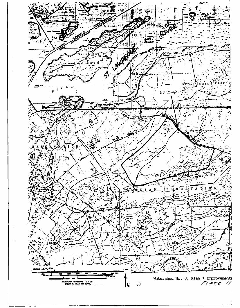
1. Plan I
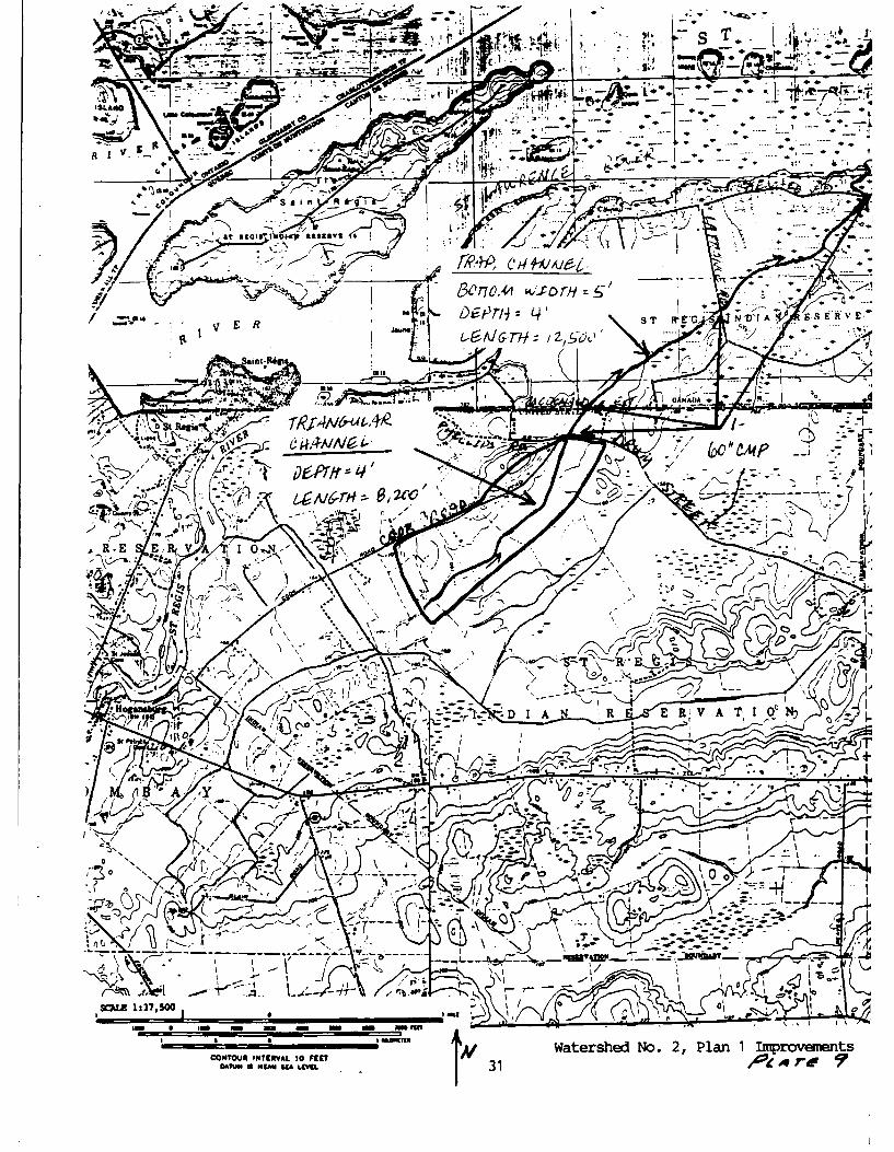
Plan 1 addresses possible culvert inadequacy at Drum Street (Plate 11).The cross-sectional area of the existing box culvert is slightly greater thanthat of a 60-inch diameter pipe. If the observation described aboveindicates additional culverts are warranted, the cost of installing one more60-in. cmp would be $21,000, as presented in Table 9.
Table 9. Costs for Watershed No. 3, Plan 1
UnitEstimated Price Cost
Item Description Quantity Unit ($) ($1,000)
60-inch cmp 45 lin. ft. 155 7.0
Bit,;minous roadway 85 lin. ft. 85 7.2
Total contractor's earnings 14.2
Contingencies (25%) 3.6
Total contractor's earnings w/contingencies 17.8
Engineering and design (6%) 1.1
Supervision and administration (12%) 2.2
Total construction cost 21.2
18
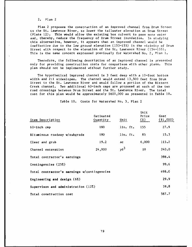
2. Plan 2
Plan 2 proposes the construction of an improved channel from Drum Streetto the St. Lawrence River, to lower the tailwater elevation at Drum Street(Plate 12). This would allow the existing box culvert to pass more waterand, thereby, reduce the frequency of Drum Street inundation. In studyingthis alternative, however, it appears that an improved channel would beineffective due to the low ground elevation (153-155) in the vicinity of DrumStreet with respect to the elevation of the St. Lawrence River (154-155).This is the same concern expressed previously for Watershed No. 2, Plan 1.
Therefore, the following description of an improved channel is presentedonly for providing construction costs for comparison with other plans. Thisplan should not be implemented without further study.
The hypothetical improved channel is 3 feet deep with a 10-foot bottomwidth and 2:1 sideslopes. The channel would extend 13,500 feet from DrumStreet to the St. Lawrence River and would follow a portion of the BitternCreek channel. Two additional 60-inch cmps are proposed at each of the tworoad crossings between Drum Street and the St. Lawrence River. The totalcost for this plan would be approximately $600,000 as presented in Table 10.
Table 10. Costs for Watershed No. 3, Plan 2
UnitEstimated Price Cost
Item Description Quantity Unit ($) ($1,000)
60-inch cmp 180 lin. ft. 155 27.9
Bituminous roadway w/subgrade 180 lin. ft. 85 15.3
Clear and grub 19.2 ac 6,000 115.2
Channel excavation 24,000 yd3 10 240.0
Total contractor's earnings 398.4
Contingencies (25%) 99.6
Total contractor's earnings w/contingencies 498.0
Engineering and design (6%) 29.9
Supervison and administration (12%) 59.8
Total construction cost 587.7
19

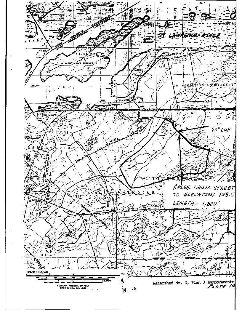
3. Plan 3
Increasing the elevation of Drum Street is likely to be more effectivethan enlarging the downstream channel for reducing road inundation. Plate 13shows the profile of Drum Street in the vicinity of Watershed No. 3, asdetermined from NYSDOT, April 1987, road profiles. The lowest portion of theroad is at el. 157.4, the second lowest at 158.5. This plan proposes raisingthe lowest portion of the road from el. 157.4 to 158.5, an increase in heightof 1.1 feet over a distance of 1,600 feet (Plates 13 and 14).
It may be desirable to add a 60-inch cmp alongside the existing boxculvert while the road is being raised. Therefore, the placement of anadditional culvert is included in this plan. The total cost associated withPlan 3 would be approximately $210,000 and is shown in Table 11.
Table 11. Costs for Watershed No. 3, Plan 3
UnitEstimated Price Cost
Item Description Quantity Unit ($) ($1,000)
60-inch cmp 45 lin. ft. 155 7.0
Bituminous roadway w/subgrade 1,600 lin. ft. 85 136.0
Total contractor's earnings 143.0
Contingencies (25%) 35.8
Total contractor's earnings w/contingencies 178.8
Engineering and design (6%) 10.7
Supervision and administration (12%) 21.5
Total construction cost 211.0
20
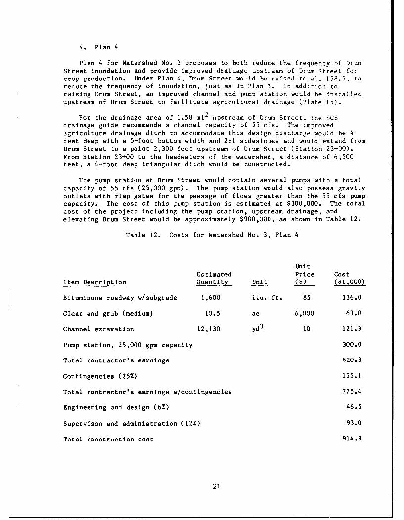
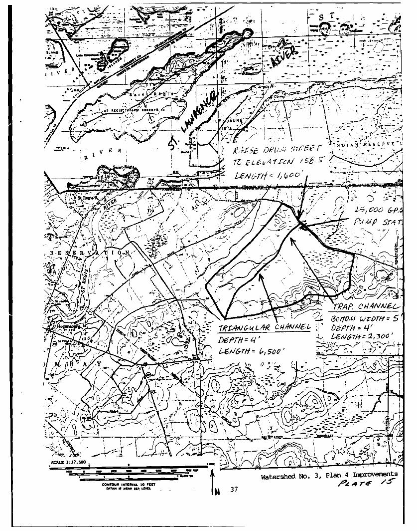
4. Plan 4
Plan 4 for Watershed No. 3 proposes to both reduce the frequency of DrunStreet inundation and provide improved drainage upstream of Drum Street for
crop production. Under Plan 4, Drum Street would be raised to el. 158.5, to
reduce the frequency of Inundation, just as in Plan 3. In addition toraising Drum Street, an improved channel and pump station would be installedupstream of Drum Street to facilitate agricultural drainage (Plate 15).
For the drainage area of 1.58 mi 2 upstream of Drum Street, the SCSdrainage guide recommends a channel capacity of 55 cfs. The improved
agriculture drainage ditch to accommodate this design discharge would be 4
feet deep with a 5-foot bottom width and 2:1 sideslopes and would extend fromDrum Street to a point 2,300 feet upstream of Drum Street (Station 23+00).From Station 23+00 to the headwaters of the watershed, a distance of 6,500feet, a 4-foot deep triangular ditch would be constructed.
The pump station at Drum Street would contain several pumps with a total
capacity of 55 cfs (25,000 gpm). The pump station would also possess gravity
outlets with flap gates for the passage of flows greater than the 55 cfs pump
capacity. The cost of this pump station is estimated at $300,000. The totalcost of the project including the pump station, upstream drainage, andelevating Drum Street would be approximately $900,000, as shown in Table 12.
Table 12. Costs for Watershed No. 3, Plan 4
Unit
Estimated Price Cost
Item Description Quantity Unit ($) ($1,000)
Bituminous roadway w/subgrade 1,600 lin. ft. 85 136.0
Clear and grub (medium) 10.5 ac 6,000 63.0
Channel excavation 12,130 yd3 10 121.3
Pump station, 25,000 gpm capacity 300.0
Total contractor's earnings 620.3
Contingencies (25%) 155.1
Total contractor's earnings w/contingencies 775.4
Engineering and design (6%) 46.5
Supervison and administration (12%) 93.0
Total construction cost 914.9
21
E. Recommendations
Of the 4 plans, Plan 3 is the presently recommended plan. Plans Iand 2 appear to be less effective than Plan 3 in reducing the magnituie andfrequency of Drum Street flooding. The implementation of Plan 4 should not
take place until residential or agricultural development of Watershed No. 3
requires improved drainage.
5. RECOMMENDATIONS FOR FUTURE STUDIES
All plans of improvement presented in this report were based on available
approximate topographic and survey data. Therefore, before any plan is
implemented, it should undergo a final design analysis based on accuratesurvey and topographic data.
In addition, the 1987 average (mean) water level of the St. Lawrence
River (approx. el. 155 ft NGVD) was used as the downstream design condition
for all plans of improvement. Increases in the water levels of the St.
Lawrence and St. Regis Rivers above el. 155, which presently occur during
spring runoff and peak power generation periods, reduce the effectiveness of
gravity drainage improvements such as Plans 1, 2, and 3 for 'Watershed No. I.
Therefore, before any gravity drainage improvement is implemented, a study
should be performed to determine the stage-frequency relationship for the St.
Lawrence and St. Regis Rivers, and the effectiveness of the plans evaluated
in conjunction with the downstream stage-frequency conditions.
Given the above uncertainties with respect to the preliminary designs of
plans of improvement presented in this report, it is recommended that the St.
Regis Mohawk Tribe pursue additional funding for a second stage of study
which would provide detailed ditch and road surveys, refinement of the
hydrologic analysis including the determination of the St. Regis River andSt. Lawrence River stage-frequency relationship, and the final design andcost of construction for any selected plans of improvement.
22
. ..- . ... ...
v -b
e -
to J
mks 4 tV'
n~V I
V~*or~b -I~- I A N- *R E EVAT
S~ T Fm f-
E R
CONT~ftINTEVAL30 VCT?
"A fEL N 23 WateshedLoction/2~~7~r
N
1-1*>
1~~~ -~-~ *
~' -~ V
0 C'
G 0
I) ____ --
____ - - . - -~ t~k
-I' -.
______ I I. ~ ul
* I * * -I'
___ ~: *~ ___ ___
_____ I 4 _____ _____ 7-..---- - A~~~: i~! 7~__
I _ _ 4
ii ci
~-~--~i -~ - 1-__-- -~ - _
__ --1 _ _
_ I
-L I I--4- -- - - I
~ I
24 2
• -% )-.-s -,
;___ ) -I - '1 _ _ _
:4L4
, I , .,. - ; ..
. . .. . . . ... .. ..r, 4 -"J7J
t4-
---- ~ -----
i 7+H._V _.-~ -2--v-- _ ~~17
F ~1~.~.~ __ ____25
UA060
Los c 0~ %~ER E
7i9A~ eAA/di.~ f..41
~Z7c .. . ....o ....:PO'\.it XF \ *JCTA (~~H
S's i d~g 4no'c N~V/ e4q
ST RtISIIII _____ ____
E 'I
.4, Sofm L-t~-qz8
8tDlLADT#'60S
- r -I
fit~ IT/",~Ae
"0C
t Z.
_______________ Ao* ,m mU m
Watershed,4j egW1APa 1IrpovUet
COIOUUI~TNVA 10V Lt ~TUU NUNUA I.VUI'
So . .... ...P?- --
NZY4N
f ~~ V I AN
INK-
1307TC3 3370'
aN rli
im 5 mm mLmu murm
I~g::/ ,.urd n1 1c gS-N
COTU40.VLt ~W trhdN.~, ln2ipoeet
S~ur .*5 LU.j 7 N

-Its
SL Loft~I
'
50
-3
-P -
ST__ 1 1) 1 A -:.t E_ S~ E R \- E
X3r~ St Rcg 3c'I-'R
-7-r V~
Hog, 0 1 A R E RV A T I 2
/ *4 ~.32B
7 7500 ('\> ~." 01
m~L .; m7 __ ,...-:U
CONTOUR INTERVL IEE Watershed No. 1, Plan 3 ImprovenoDATU 4 EN A1." 28 -z I7e

*~~~~~~T -- jr.- '-I 2 -"vL #
-7
ONO!*T ~
go +
INt Ek'~ It v r 'IE R
-n;iki . ..... £i4~ '... . U m
vr-. V. I . i
COURITRVLtOfCI~, 7
A4U 6 r~ V-r LN 29,R.__ _ _ _ _ _ __ _ _ _ _ _ _ _ __ _ _ _ _ _ _ _ IxIyO N IWve~ent 7
IN~
... ... . .
* ~*tLA
* -.-.0"
A7 re* ~1 30
__ S It* I . 5
01 Sa n
r FC h
Scol I. wr Atilg vs .....
Mir"~~ ~ ~ -4fme ..
&776),4A "*r
E 4S t- NViuIni~ Aggt 'S S t-
'a -A - .. .. ..
I; int;R41
Pi OAnA4
W4A16/i \J' -
Lfl\
E v 1 0
F5//
Ilk-K- ".
A -Y
A~ 0'
X" //K
/*' I -- -. C
r'-A~i -:i.. Raw
,f _3 -4 'u~-
I .,I
ERIC atershed No. 2, Plan 1 Iniprovenents

+~~ -lw
=,a to I~~S T Hr-,1 G AI N D IA R E S E R%
R.E~~~ ERVA RIO.N
4D IA R.. ER VAII
9fNA) '<
,'. 1 k I -,
It ~ -D
R-E 1:37 -, i 5-
0z
- ' -- - PUZ
-- v E
CONTUR it~m~i.I~ aterhedNo. , Pan Impoveent
D ICA A* RIW E R;V A TI
-W4
or .. g-,
I state IbI4 R95IV VN*\ -~
I L JN
1) 1. A SE
~~~ 0 jaw"' '~ , ., (
&0 '-c -2
Sa nt -a,
A4I-
Waerhe No 3, Pla 1 Atrv~et
CONTOU INERA A0 EEE R i N
1: 37, SOO~ /

A4k~ .& -'4-.
an Q
-U,~ arr,'
.-.
S__ > 4tl v~v ~cav
7 ER ae~~~L(,/L I ALar
/V/
at 6 S E R
R: t)--
D St PA&i.*.
IsI
I A N E R- .10
IZ :150~~.L0m e
I 0 IuIlk,
CONTOUR~~~~~~~~~~~l N1NM3 jT NWtrhd o ,Pa 2IpofeD~tUMIS MAU IA g~u 34L~~ 477 /

.... -- - - -t .... , ....- - ! \ ; . ....-t-.... -- -n---
_ _ ' _ _ , ;i t ;-J- 1 -- ... __ _ _ __ _ _ '_.4l._
-I.I c'1
.. .I .! - i-I., _....
- - _.... .. . -
[1 35
S. T .
Ow n -
- 6 7
VL qbUN -1
E7 R
. .... .. ...
g446 DMA A4 rkAV~ R.ecW1~'//5
-% %
* 0
Am .~
;L ~.UtWaesessa roeet
CONTUR ITERVL tOrEP
DRUM
'A. A- IYN
T
I~ WWA ~ .- ,
V It
c, C)
V.~___ R.& ... .. . ~ -
~ g4r~~ )et.~ 57~s~r N1!K~COO~1
rip
N..
Pg.OU :2,mAI No 0~ Pln40p0~~f