ssp330 - the diesel particulate filter system with · pdf filetypical particle of soot caused...
TRANSCRIPT

Service Training
Self-study programme 330
The diesel particulate filter system with additive
Design and Function

2
Combustion will remain in the foreseeable future an important method of energy conversion, whether in power stations, cars – or even fireplaces.
Every fire leaves behind harmful by-products of combustion - particles of soot for example. The aim is to avoid risks to the environment and health caused by the generation and release of carbon soot.
These aspects and strict emissions legislation have led engineers to place particular emphasis on the conti-nual reduction of particulate emissions.
One way to reduce the emission of carbon soot is with a diesel particulate filter.
S330_001
Further information on the subject of exhaust gas can be found in the following self-study programmes:
● SSP 124: Diesel engine with catalytic converter● SSP 230: Vehicle exhaust emissions● SSP 315: European onboard diagnosis for diesel engines
NEW CautionNote
The self-study programme represents the design and function of new developments!The contents will not be updated.
For current testing, adjustment and repair instruc-tions, refer to the relevant service literature.
3
Contents
Introduction . . . . . . . . . . . . . . . . . . . . . . . . . . . . . . . . . . . . . . . . . . 4
Design and function . . . . . . . . . . . . . . . . . . . . . . . . . . . . . . . . . . . 12
System overview. . . . . . . . . . . . . . . . . . . . . . . . . . . . . . . . . . . . . . 19
Sensors and actuators . . . . . . . . . . . . . . . . . . . . . . . . . . . . . . . . 20
Functional diagram . . . . . . . . . . . . . . . . . . . . . . . . . . . . . . . . . . . 31
System limits . . . . . . . . . . . . . . . . . . . . . . . . . . . . . . . . . . . . . . . . .32
Service . . . . . . . . . . . . . . . . . . . . . . . . . . . . . . . . . . . . . . . . . . . . . .33
Test yourself. . . . . . . . . . . . . . . . . . . . . . . . . . . . . . . . . . . . . . . . . 35
4
Introduction
General
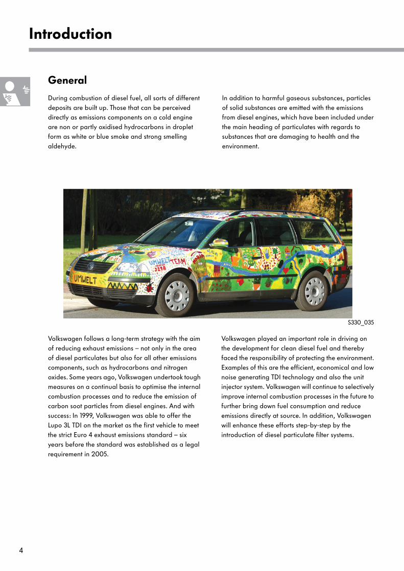
During combustion of diesel fuel, all sorts of different deposits are built up. Those that can be perceived directly as emissions components on a cold engine are non or partly oxidised hydrocarbons in droplet form as white or blue smoke and strong smelling aldehyde.
In addition to harmful gaseous substances, particles of solid substances are emitted with the emissions from diesel engines, which have been included under the main heading of particulates with regards to substances that are damaging to health and the environment.
S330_035
Volkswagen follows a long-term strategy with the aim of reducing exhaust emissions – not only in the area of diesel particulates but also for all other emissions components, such as hydrocarbons and nitrogen oxides. Some years ago, Volkswagen undertook tough measures on a continual basis to optimise the internal combustion processes and to reduce the emission of carbon soot particles from diesel engines. And with success: In 1999, Volkswagen was able to offer the Lupo 3L TDI on the market as the first vehicle to meet the strict Euro 4 exhaust emissions standard – six years before the standard was established as a legal requirement in 2005.
Volkswagen played an important role in driving on the development for clean diesel fuel and thereby faced the responsibility of protecting the environment. Examples of this are the efficient, economical and low noise generating TDI technology and also the unit injector system. Volkswagen will continue to selectively improve internal combustion processes in the future to further bring down fuel consumption and reduce emissions directly at source. In addition, Volkswagen will enhance these efforts step-by-step by the introduction of diesel particulate filter systems.
5
The exhaust gas
Emissions standards
In the Republic of Germany, across Europe and throughout the world, laws have been passed in recent years to reduce the emission of harmful substances in the air. In Europe, the emissions standards are categorised from EU1 to EU4. These prescribe emission limits to the automobile industry for type approval of new vehicle models.
EU3
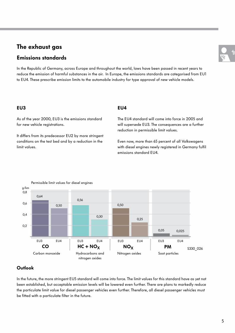
As of the year 2000, EU3 is the emissions standard for new vehicle registrations.
It differs from its predecessor EU2 by more stringent conditions on the test bed and by a reduction in the limit values.
EU4
The EU4 standard will come into force in 2005 and will supersede EU3. The consequences are a further reduction in permissible limit values.
Even now, more than 65 percent of all Volkswagens with diesel engines newly registered in Germany fulfil emissions standard EU4.
S330_026
0,2
0,6
0,4
0,8g/km
HC + NOXCO PMNOX
EU3 EU4 EU3 EU4 EU3 EU4 EU3 EU4
0,64
0,50
0,56
0,30
0,50
0,25
0,05 0,025
Carbon monoxide Hydrocarbons and nitrogen oxides
Nitrogen oxides Soot particles
Permissible limit values for diesel engines
Outlook
In the future, the more stringent EU5 standard will come into force. The limit values for this standard have as yet not been established, but acceptable emission levels will be lowered even further. There are plans to markedly reduce the particulate limit value for diesel passenger vehicles even further. Therefore, all diesel passenger vehicles must be fitted with a particulate filter in the future.
6
Introduction
Harmful substances caused by combustion
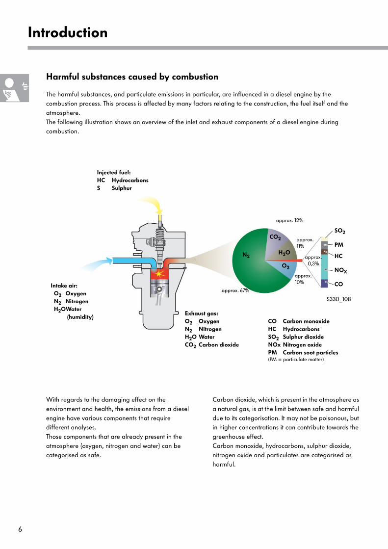
The harmful substances, and particulate emissions in particular, are influenced in a diesel engine by the combustion process. This process is affected by many factors relating to the construction, the fuel itself and the atmosphere.The following illustration shows an overview of the inlet and exhaust components of a diesel engine during combustion.
approx. 67%
CO2
H2ON2
approx. 12%
approx. 11%
HC
NOX
CO
O2
SO2
PM
approx. 0,3%
approx. 10%
S330_108
Injected fuel: HC HydrocarbonsS Sulphur
Intake air: O2 Oxygen N2 Nitrogen H2OWater
(humidity)Exhaust gas:O2 OxygenN2 NitrogenH2O Water CO2 Carbon dioxide
CO Carbon monoxideHC HydrocarbonsSO2 Sulphur dioxideNOx Nitrogen oxidePM Carbon soot particles(PM = particulate matter)
With regards to the damaging effect on the environment and health, the emissions from a diesel engine have various components that require different analyses. Those components that are already present in the atmosphere (oxygen, nitrogen and water) can be categorised as safe.
Carbon dioxide, which is present in the atmosphere as a natural gas, is at the limit between safe and harmful due to its categorisation. It may not be poisonous, but in higher concentrations it can contribute towards the greenhouse effect. Carbon monoxide, hydrocarbons, sulphur dioxide, nitrogen oxide and particulates are categorised as harmful.
7
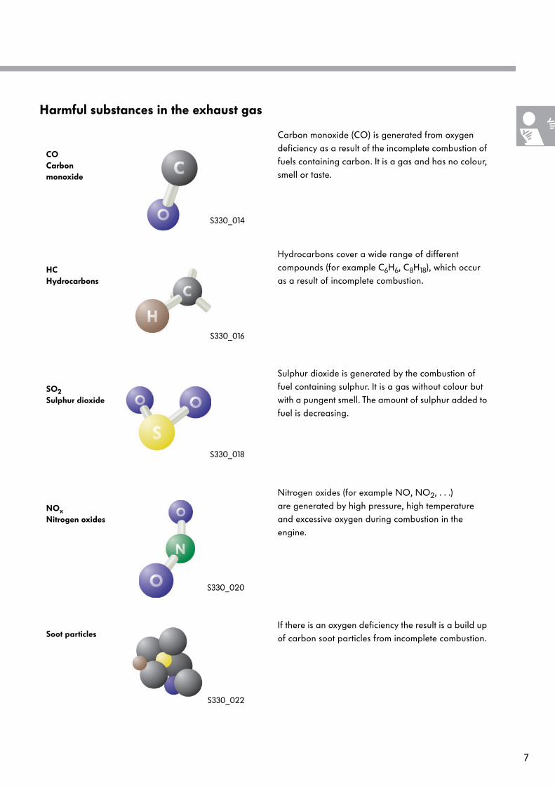
Harmful substances in the exhaust gas
S330_014
CO Carbon monoxide
Carbon monoxide (CO) is generated from oxygen deficiency as a result of the incomplete combustion of fuels containing carbon. It is a gas and has no colour, smell or taste.
S330_016
HCHydrocarbons
Hydrocarbons cover a wide range of different compounds (for example C6H6, C8H18), which occur as a result of incomplete combustion.
S330_018
SO2Sulphur dioxide
Sulphur dioxide is generated by the combustion of fuel containing sulphur. It is a gas without colour but with a pungent smell. The amount of sulphur added to fuel is decreasing.
S330_020
NOxNitrogen oxides
Nitrogen oxides (for example NO, NO2, . . .) are generated by high pressure, high temperature and excessive oxygen during combustion in the engine.
S330_022
Soot particlesIf there is an oxygen deficiency the result is a build up of carbon soot particles from incomplete combustion.

8
Introduction
The particulates
Particulates is a term that covers all particles, solid or liquid, that are generated from friction, breakdown of components, erosion, condensation and incomplete combustion. These processes create particulates in different shapes, sizes and structures.
Particulates have the same character as harmful substances in the air if, due to their small dimensions, they can float around in gaseous substances and damage organisms.
Soot particles
Soot particles are generated from the combustion process in a diesel engine. Soot particles are microscopic balls of carbon with a diameter of about 0.05 µm. Their core consists of pure carbon. Around the core are deposits of different hydrocarbon compounds, metal oxides and sulphur.
Some hydrocarbon compounds are categorised as potentially hazardous to health. The exact composition of soot particles depends on the engine technology, the conditions of use and the type of fuel.
Carbon
HydrocarbonsSO4 (sulphate)
Sulphur and metal oxides
H2O (water)
S330_182
9
Cause of soot particles
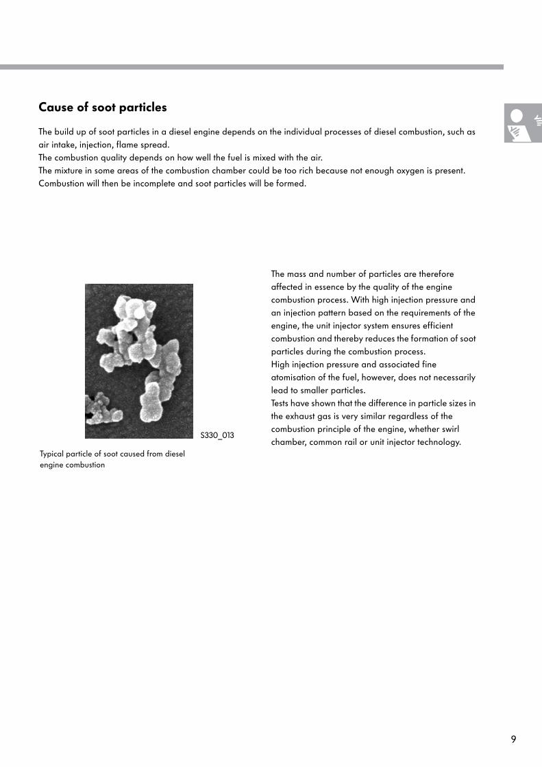
The build up of soot particles in a diesel engine depends on the individual processes of diesel combustion, such as air intake, injection, flame spread. The combustion quality depends on how well the fuel is mixed with the air.The mixture in some areas of the combustion chamber could be too rich because not enough oxygen is present. Combustion will then be incomplete and soot particles will be formed.
Typical particle of soot caused from diesel engine combustion
S330_013
The mass and number of particles are therefore affected in essence by the quality of the engine combustion process. With high injection pressure and an injection pattern based on the requirements of the engine, the unit injector system ensures efficient combustion and thereby reduces the formation of soot particles during the combustion process. High injection pressure and associated fine atomisation of the fuel, however, does not necessarily lead to smaller particles.Tests have shown that the difference in particle sizes in the exhaust gas is very similar regardless of the combustion principle of the engine, whether swirl chamber, common rail or unit injector technology.
10
Introduction
The measures to reduce particulates
The reduction of exhaust emissions in a diesel engine is an important aim in further development. To reduce exhaust emissions there is a series of different technical solutions. Here, a difference is made between internal and external engine measures.
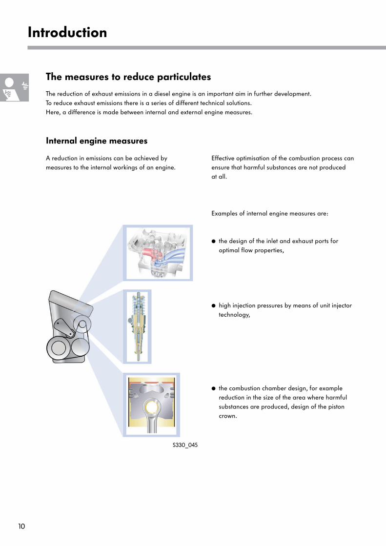
Internal engine measures
A reduction in emissions can be achieved by measures to the internal workings of an engine.
Effective optimisation of the combustion process can ensure that harmful substances are not produced at all.
S330_045
Examples of internal engine measures are:
● the design of the inlet and exhaust ports for optimal flow properties,
● high injection pressures by means of unit injector technology,
● the combustion chamber design, for example reduction in the size of the area where harmful substances are produced, design of the piston crown.
11
External engine measures
The release of soot particles that are produced during combustion can be prevented by external engine measures. This can be seen as the reduction of soot particles by means of a particulate filter system.To do this, it is necessary to differentiate between two systems – the diesel particulate filter with additive and the diesel particulate filter without additive. Explained on the following pages is exclusively the design and function of the diesel particulate filter systems with additive, currently used by Volkswagen.
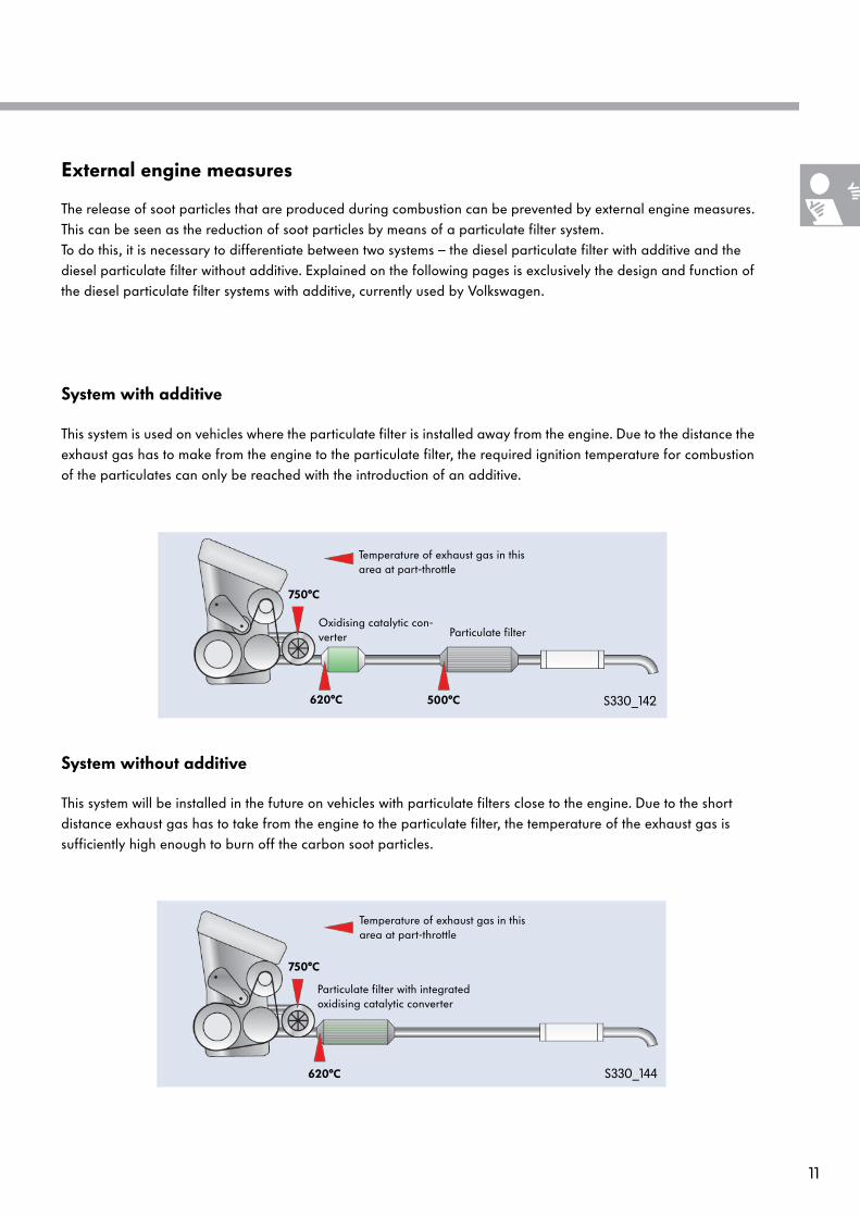
System with additive
This system is used on vehicles where the particulate filter is installed away from the engine. Due to the distance the exhaust gas has to make from the engine to the particulate filter, the required ignition temperature for combustion of the particulates can only be reached with the introduction of an additive.
S330_142
750°C
620°C 500°C
Oxidising catalytic con-verter Particulate filter
Temperature of exhaust gas in this area at part-throttle
System without additive
This system will be installed in the future on vehicles with particulate filters close to the engine. Due to the short distance exhaust gas has to take from the engine to the particulate filter, the temperature of the exhaust gas is sufficiently high enough to burn off the carbon soot particles.
S330_144
750°C
620°C
Particulate filter with integrated oxidising catalytic converter
Temperature of exhaust gas in this area at part-throttle
12
Design and function
The diesel particulate filter system with additive
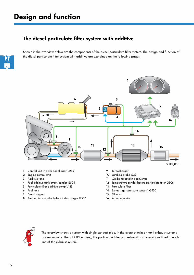
Shown in the overview below are the components of the diesel particulate filter system. The design and function of the diesel particulate filter system with additive are explained on the following pages.
1
2
4
5
6
9
14
15
7
S330_030
8
10 1112
13
3
1 Control unit in dash panel insert J2852 Engine control unit3 Additive tank4 Fuel additive tank empty sender G5045 Particulate filter additive pump V1356 Fuel tank7 Diesel engine8 Temperature sender before turbocharger G507
9 Turbocharger10 Lambda probe G3911 Oxidising catalytic converter12 Temperature sender before particulate filter G50613 Particulate filter14 Exhaust gas pressure sensor 1 G45015 Silencer16 Air mass meter
16
The overview shows a system with single exhaust pipe. In the event of twin or multi exhaust systems (for example on the V10 TDI engine), the particulate filter and exhaust gas sensors are fitted to each line of the exhaust system.
13
The particulate filter
S330_017
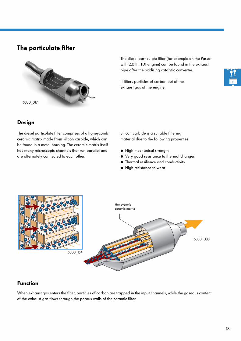
The diesel particulate filter (for example on the Passat with 2.0 ltr. TDI engine) can be found in the exhaust pipe after the oxidising catalytic converter.
It filters particles of carbon out of the exhaust gas of the engine.
Design
The diesel particulate filter comprises of a honeycomb ceramic matrix made from silicon carbide, which can be found in a metal housing. The ceramic matrix itself has many microscopic channels that run parallel and are alternately connected to each other.
Silicon carbide is a suitable filtering material due to the following properties:
● High mechanical strength● Very good resistance to thermal changes● Thermal resilience and conductivity● High resistance to wear
S330_038
Honeycomb ceramic matrix
S330_154
Function
When exhaust gas enters the filter, particles of carbon are trapped in the input channels, while the gaseous content of the exhaust gas flows through the porous walls of the ceramic filter.

14
Design and function
Regeneration
The diesel particulate filter must be cleaned of the particles of regularly to prevent it from becoming blokked and its function thereby being affected. During the regeneration phase, the particles of carbon stored in the filter are burnt off at a temperature of approx. 500°C. The actual ignition temperature of the particulates is about 600-650°C. This exhaust gas temperature can only be reached on a diesel engine at full throttle.
In order to ensure regeneration of the diesel particu-late filter under all operating conditions, the ignition temperature of the carbon is lowered by the introduction of an additive, and the exhaust gas temperature is raised by the engine management system.
The regeneration procedure is initiated by the engine control unit.
Particulate filter empty = low resistance to flow
Exhaust gas pressure sensor 1 G450
Signals to engine control unit
S330_042
Temperature senderbefore particulate filter G506
Air mass meter G70
Particulate filter empty
S330_044
Particulate filter full = high resistance to flow
Exhaust gas pressure sensor 1 G450Temperature sender
before particulate filter G506
Air mass meter G70
Signals to engine control unit
Particulate filter full
15
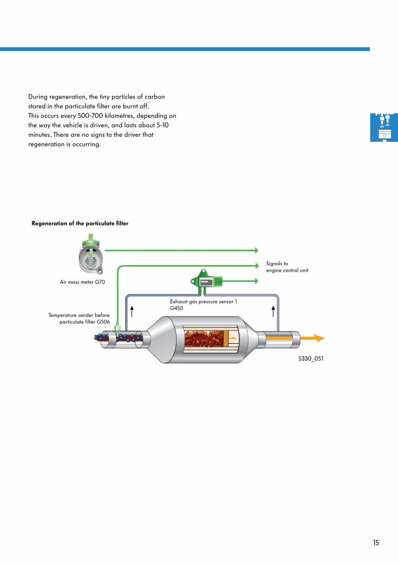
During regeneration, the tiny particles of carbon stored in the particulate filter are burnt off. This occurs every 500-700 kilometres, depending on the way the vehicle is driven, and lasts about 5-10 minutes. There are no signs to the driver that regeneration is occurring.
Exhaust gas pressure sensor 1 G450
S330_051
Temperature sender beforeparticulate filter G506
Air mass meter G70
Signals to engine control unit
Regeneration of the particulate filter
16
Design and function
The additive
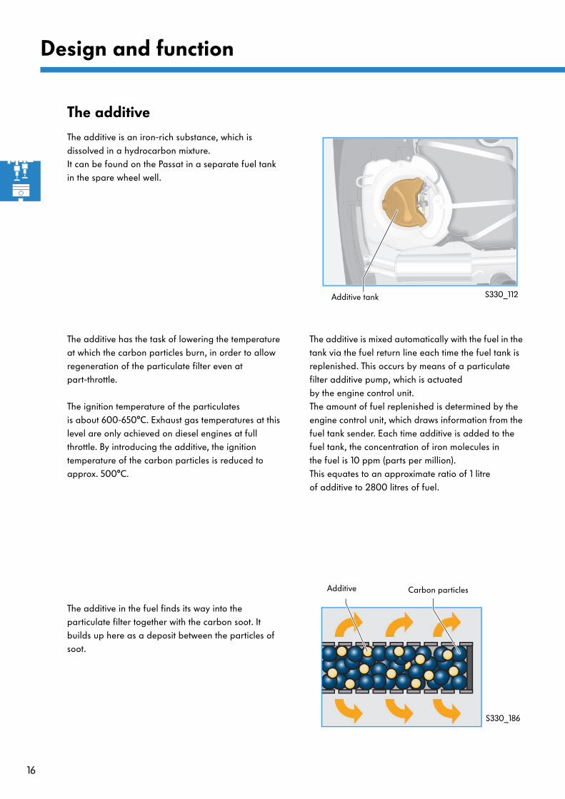
The additive is an iron-rich substance, which is dissolved in a hydrocarbon mixture. It can be found on the Passat in a separate fuel tank in the spare wheel well.
S330_112Additive tank
The additive has the task of lowering the temperature at which the carbon particles burn, in order to allow regeneration of the particulate filter even at part-throttle.
The ignition temperature of the particulates is about 600-650°C. Exhaust gas temperatures at this level are only achieved on diesel engines at full throttle. By introducing the additive, the ignition temperature of the carbon particles is reduced to approx. 500°C.
The additive is mixed automatically with the fuel in the tank via the fuel return line each time the fuel tank is replenished. This occurs by means of a particulate filter additive pump, which is actuated by the engine control unit. The amount of fuel replenished is determined by the engine control unit, which draws information from the fuel tank sender. Each time additive is added to the fuel tank, the concentration of iron molecules in the fuel is 10 ppm (parts per million). This equates to an approximate ratio of 1 litre of additive to 2800 litres of fuel.
The additive in the fuel finds its way into the particulate filter together with the carbon soot. It builds up here as a deposit between the particles of soot.
Additive Carbon particles
S330_186
17
Level of carbon deposit in particulate filter
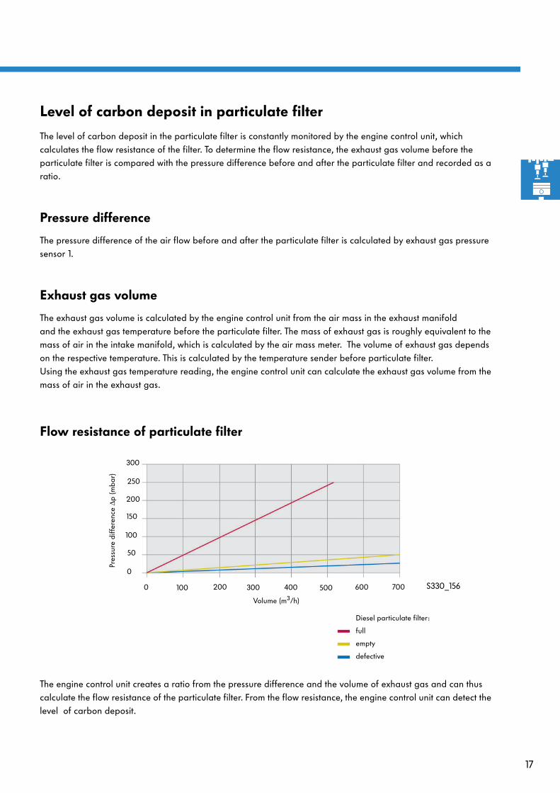
The level of carbon deposit in the particulate filter is constantly monitored by the engine control unit, which calculates the flow resistance of the filter. To determine the flow resistance, the exhaust gas volume before the particulate filter is compared with the pressure difference before and after the particulate filter and recorded as a ratio.
Pressure difference
The pressure difference of the air flow before and after the particulate filter is calculated by exhaust gas pressure sensor 1.
Exhaust gas volume
The exhaust gas volume is calculated by the engine control unit from the air mass in the exhaust manifold and the exhaust gas temperature before the particulate filter. The mass of exhaust gas is roughly equivalent to the mass of air in the intake manifold, which is calculated by the air mass meter. The volume of exhaust gas depends on the respective temperature. This is calculated by the temperature sender before particulate filter. Using the exhaust gas temperature reading, the engine control unit can calculate the exhaust gas volume from the mass of air in the exhaust gas.
Flow resistance of particulate filter
0 100 200 300 400 500 600 700
0
50
100
150
200
250
300
Volume (m3/h)
Pres
sure
diff
eren
ce ∆
p (m
bar)
Diesel particulate filter:
full
empty
defective
S330_156
The engine control unit creates a ratio from the pressure difference and the volume of exhaust gas and can thus calculate the flow resistance of the particulate filter. From the flow resistance, the engine control unit can detect the level of carbon deposit.
18
Engine management during regeneration
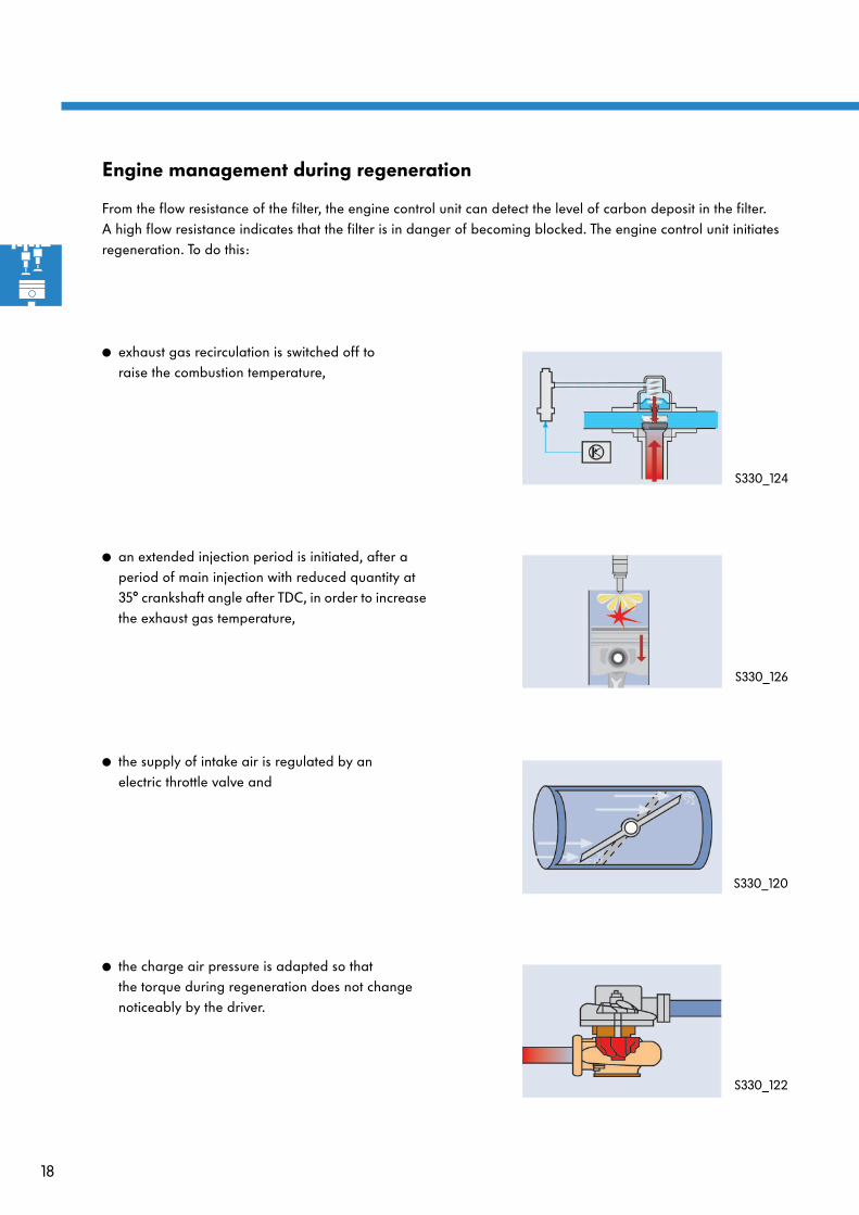
From the flow resistance of the filter, the engine control unit can detect the level of carbon deposit in the filter. A high flow resistance indicates that the filter is in danger of becoming blocked. The engine control unit initiates regeneration. To do this:
● exhaust gas recirculation is switched off to raise the combustion temperature,
S330_124
● an extended injection period is initiated, after a period of main injection with reduced quantity at 35° crankshaft angle after TDC, in order to increase the exhaust gas temperature,
S330_126
● the supply of intake air is regulated by an electric throttle valve and
S330_120
● the charge air pressure is adapted so that the torque during regeneration does not change noticeably by the driver.
S330_122
19
System overview
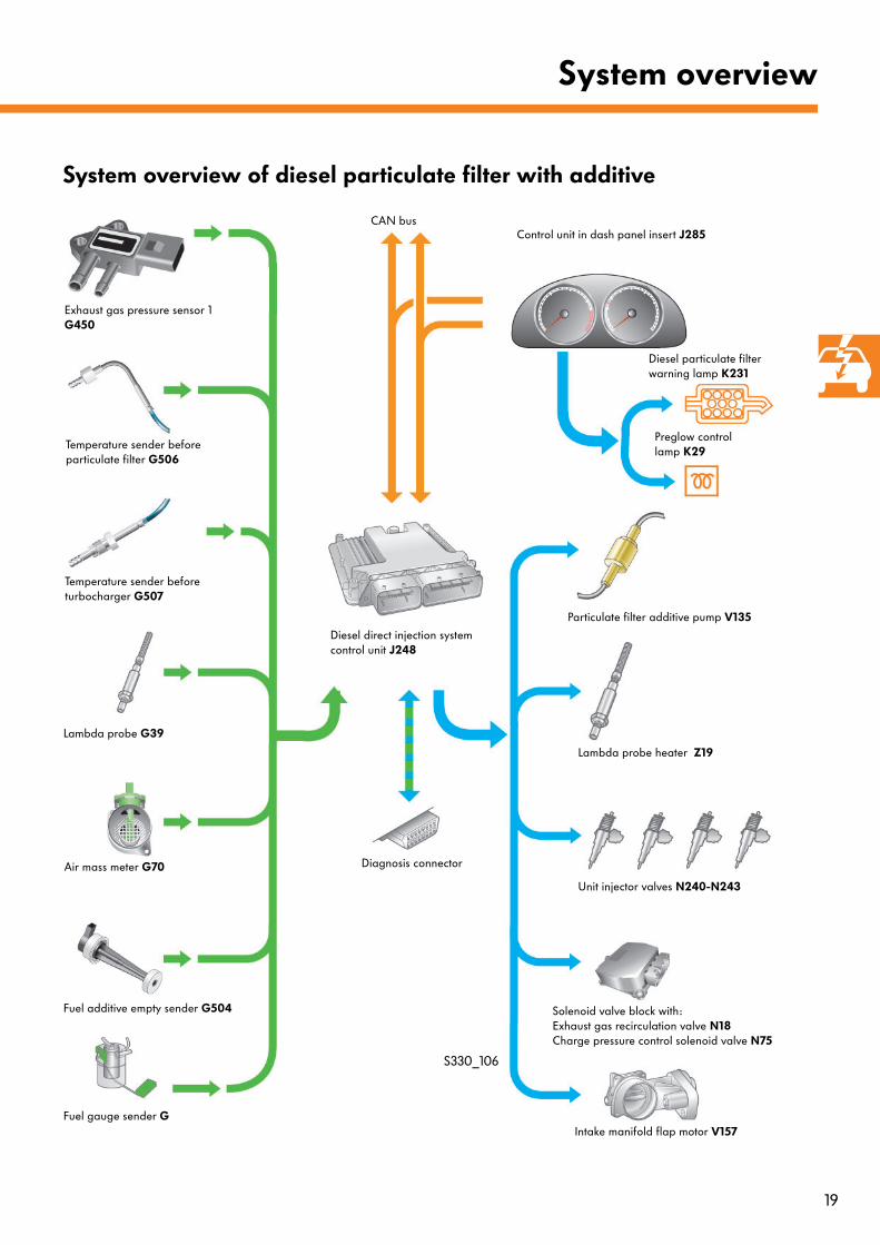
System overview of diesel particulate filter with additive
Temperature sender before particulate filter G506
Exhaust gas pressure sensor 1 G450
Lambda probe G39
Particulate filter additive pump V135
Diesel direct injection system control unit J248
Control unit in dash panel insert J285
Diesel particulate filter warning lamp K231
Diagnosis connector
CAN bus
Lambda probe heater Z19
Temperature sender before turbocharger G507
Fuel additive empty sender G504
S330_106
Air mass meter G70
Fuel gauge sender G
Preglow control lamp K29
Unit injector valves N240-N243
Solenoid valve block with:Exhaust gas recirculation valve N18Charge pressure control solenoid valve N75
Intake manifold flap motor V157
20
Sensors and actuators
The sensors
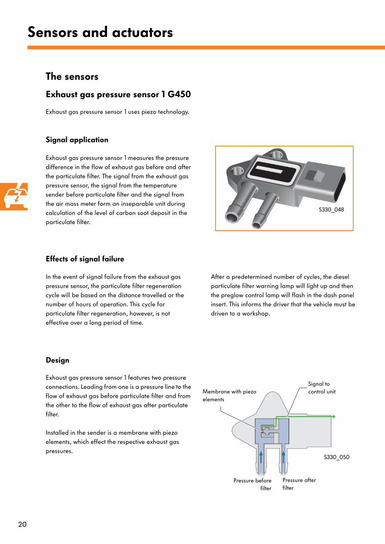
Exhaust gas pressure sensor 1 G450
Exhaust gas pressure sensor 1 uses piezo technology.
S330_048
Signal application
Exhaust gas pressure sensor 1 measures the pressure difference in the flow of exhaust gas before and after the particulate filter. The signal from the exhaust gas pressure sensor, the signal from the temperature sender before particulate filter and the signal from the air mass meter form an inseparable unit during calculation of the level of carbon soot deposit in the particulate filter.
Effects of signal failure
In the event of signal failure from the exhaust gas pressure sensor, the particulate filter regeneration cycle will be based on the distance travelled or the number of hours of operation. This cycle for particulate filter regeneration, however, is not effective over a long period of time.
After a predetermined number of cycles, the diesel particulate filter warning lamp will light up and then the preglow control lamp will flash in the dash panel insert. This informs the driver that the vehicle must be driven to a workshop.
Design
Exhaust gas pressure sensor 1 features two pressure connections. Leading from one is a pressure line to the flow of exhaust gas before particulate filter and from the other to the flow of exhaust gas after particulate filter.
Installed in the sender is a membrane with piezo elements, which effect the respective exhaust gas pressures.
S330_050
Signal to control unitMembrane with piezo
elements
Pressure beforefilter
Pressure after filter

21
This is how it works:
Particulate filter empty
S330_160
S330_090
Pressure before filter = pressure after filter
Piezo ele-ments
If the particulate filter has a very low carbon soot deposit level, the pressure before and after the filter is almost the same.The membrane with the piezo elements is in the rest position.
Particulate filter full
S330_162
S330_092
Pressure before filter > pressure after filter
If there is a build up of carbon soot in the particulate filter, the exhaust gas pressure rises before the filter due to a lower flow volume.The exhaust gas pressure behind the filter remains almost the same. The membrane changes its shape depending on the difference in pressure.This deformation alters the electrical resistance of the piezo elements, which are connected to form a test bridge. The output voltage of this test bridge is processed, amplified and sent by the sensor electronics as a signal voltage to the engine control unit. From this signal, the engine control unit calculates the level of carbon soot deposit in the particulate filter and initiates regeneration to clean the filter.
The level of carbon soot deposit in the particulate filter can be checked using vehicle diagnosis, testing and information system VAS 5051 as a "particulate charge coefficient" in a measured value block.

22
Sensors and actuators
Temperature sender before particulate filter G506
S330_100
S330_114
The temperature sender before particulate filter is a PTC sensor. On a sensor with PTC (positive temperature coefficient), resistance rises as temperature increases.
It can be found in the exhaust system before the diesel particulate filter. There it measures the temperature of the exhaust gas.
Signal application
Using the signal from the temperature sender before particulate filter, the engine control unit calculates the exhaust gas volume in order to determine the level of carbon soot deposit in the particulate filter.
The signal from the temperature sender before particulate filter, the signal from the air mass meter and the signal from the exhaust gas pressure sensor form an inseparable unit during calculation of the level of carbon soot deposit in the particulate filter.
Furthermore, the signal is used as a form of component protection to protect the particulate filter against high exhaust gas temperatures.
Effects of signal failure
In the event of signal failure from the temperature sender before particulate filter, the particulate filter regeneration cycle will be based on the distance travelled or the number of hours of operation.
This cycle for particulate filter regeneration, however, is not effective over a long period of time. After a predetermined number of cycles, the diesel particulate filter warning lamp will light up and then the preglow control lamp will flash in the dash panel insert. This informs the driver that the vehicle must be driven to a workshop.
23
Temperature sender before turbocharger G507
S330_096
S330_180
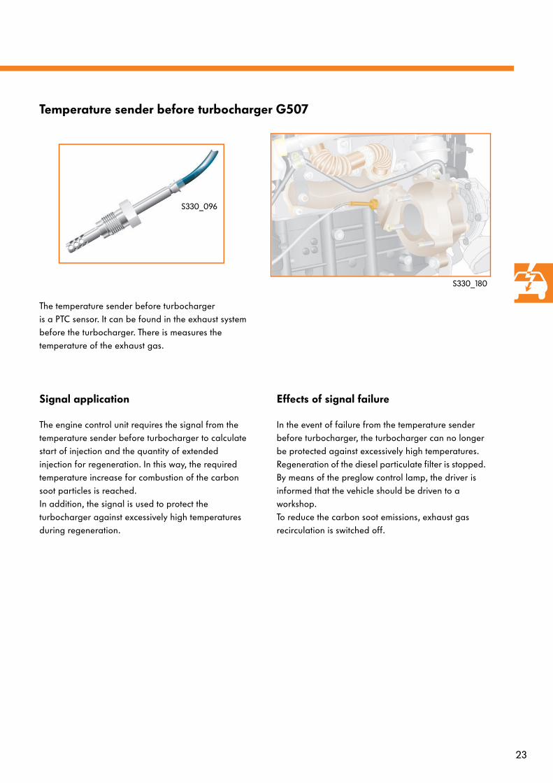
The temperature sender before turbocharger is a PTC sensor. It can be found in the exhaust system before the turbocharger. There is measures the temperature of the exhaust gas.
Signal application
The engine control unit requires the signal from the temperature sender before turbocharger to calculate start of injection and the quantity of extended injection for regeneration. In this way, the required temperature increase for combustion of the carbon soot particles is reached.In addition, the signal is used to protect the turbocharger against excessively high temperatures during regeneration.
Effects of signal failure
In the event of failure from the temperature sender before turbocharger, the turbocharger can no longer be protected against excessively high temperatures. Regeneration of the diesel particulate filter is stopped. By means of the preglow control lamp, the driver is informed that the vehicle should be driven to a workshop. To reduce the carbon soot emissions, exhaust gas recirculation is switched off.
24
Sensors and actuators
Lambda probe G39
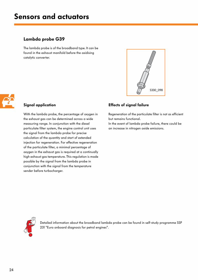
The lambda probe is of the broadband type. It can be found in the exhaust manifold before the oxidising catalytic converter.
S330_098
Signal application
With the lambda probe, the percentage of oxygen in the exhaust gas can be determined across a wide measuring range. In conjunction with the diesel particulate filter system, the engine control unit uses the signal from the lambda probe for precise calculation of the quantity and start of extended injection for regeneration. For effective regeneration of the particulate filter, a minimal percentage of oxygen in the exhaust gas is required at a continually high exhaust gas temperature. This regulation is made possible by the signal from the lambda probe in conjunction with the signal from the temperature sender before turbocharger.
Effects of signal failure
Regeneration of the particulate filter is not as efficient but remains functional. In the event of lambda probe failure, there could be an increase in nitrogen oxide emissions.
Detailed information about the broadband lambda probe can be found in self-study programme SSP 231 "Euro onboard diagnosis for petrol engines".
25
Air mass meter G70
S330_184
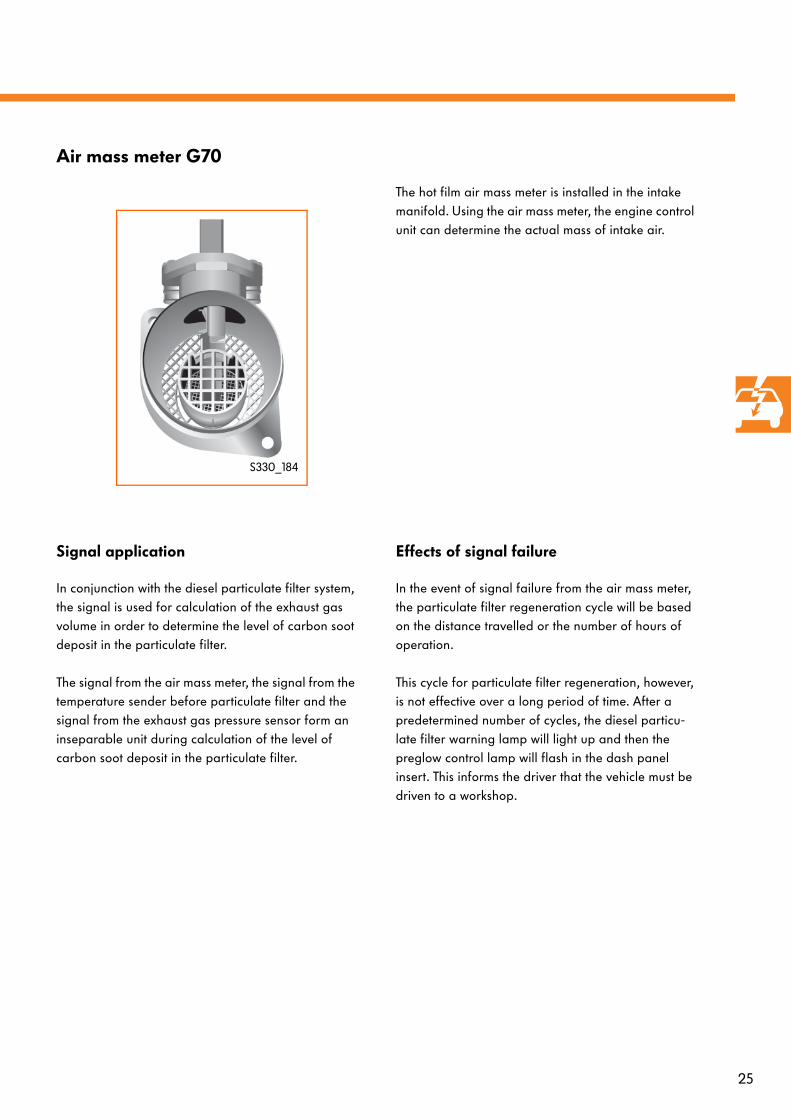
The hot film air mass meter is installed in the intake manifold. Using the air mass meter, the engine control unit can determine the actual mass of intake air.
Signal application
In conjunction with the diesel particulate filter system, the signal is used for calculation of the exhaust gas volume in order to determine the level of carbon soot deposit in the particulate filter.
The signal from the air mass meter, the signal from the temperature sender before particulate filter and the signal from the exhaust gas pressure sensor form an inseparable unit during calculation of the level of carbon soot deposit in the particulate filter.
Effects of signal failure
In the event of signal failure from the air mass meter, the particulate filter regeneration cycle will be based on the distance travelled or the number of hours of operation.
This cycle for particulate filter regeneration, however, is not effective over a long period of time. After a predetermined number of cycles, the diesel particu-late filter warning lamp will light up and then the preglow control lamp will flash in the dash panel insert. This informs the driver that the vehicle must be driven to a workshop.
26
Sensors and actuators
Fuel additive tank sender G504
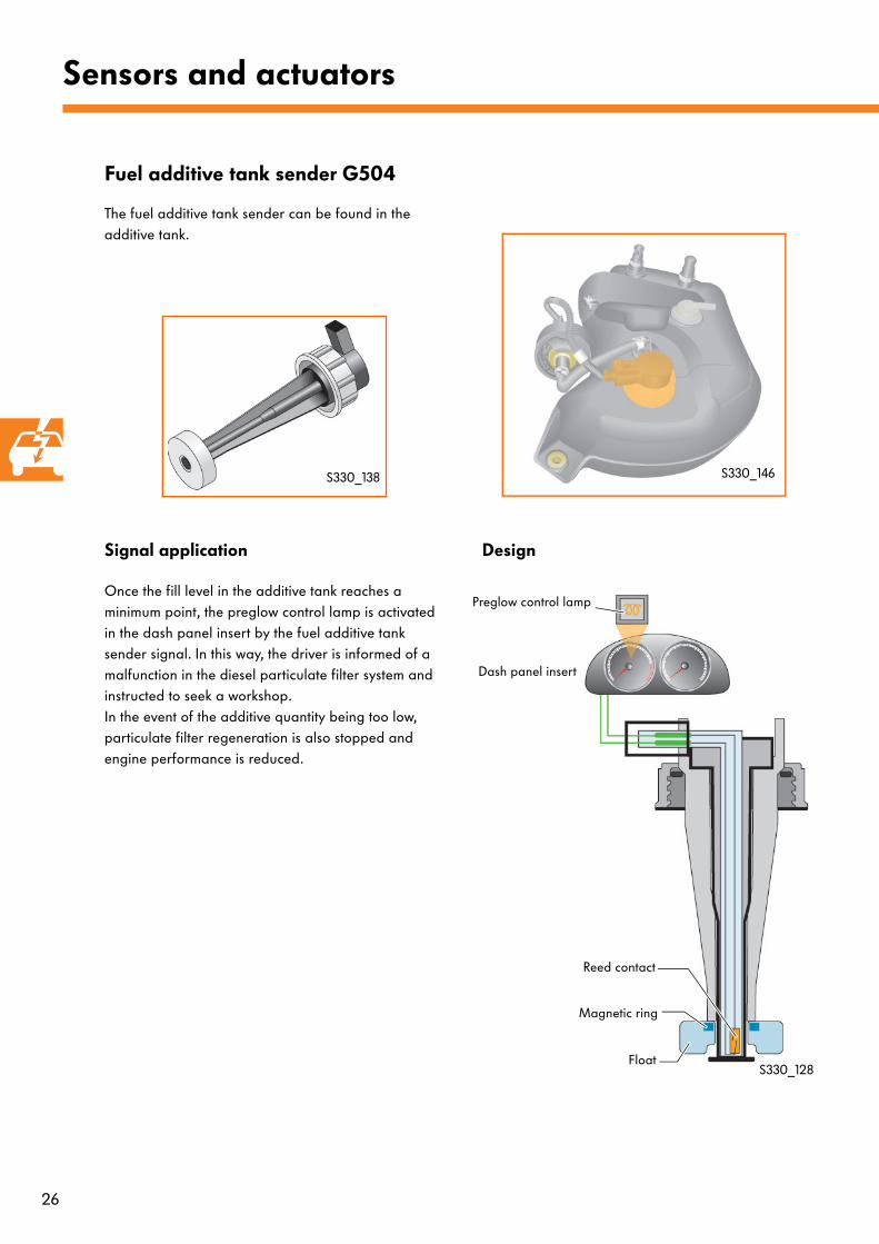
The fuel additive tank sender can be found in the additive tank.
S330_146S330_138
Signal application
Once the fill level in the additive tank reaches a minimum point, the preglow control lamp is activated in the dash panel insert by the fuel additive tank sender signal. In this way, the driver is informed of a malfunction in the diesel particulate filter system and instructed to seek a workshop. In the event of the additive quantity being too low, particulate filter regeneration is also stopped and engine performance is reduced.
Design
Float
Reed contact
Magnetic ring
Dash panel insert
S330_128
Preglow control lamp
27
This is how it works:
Reed contactFloat Magnetic ring
Additive
S330_136
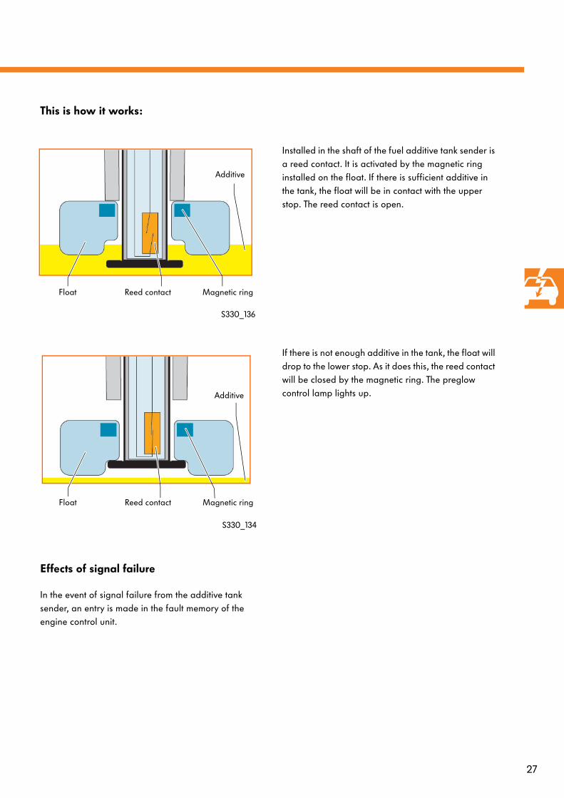
Installed in the shaft of the fuel additive tank sender is a reed contact. It is activated by the magnetic ring installed on the float. If there is sufficient additive in the tank, the float will be in contact with the upper stop. The reed contact is open.
Reed contactFloat Magnetic ring
Additive
S330_134
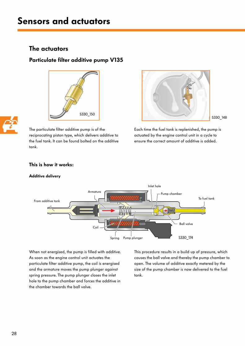
If there is not enough additive in the tank, the float will drop to the lower stop. As it does this, the reed contact will be closed by the magnetic ring. The preglow control lamp lights up.
Effects of signal failure
In the event of signal failure from the additive tank sender, an entry is made in the fault memory of the engine control unit.
28
Sensors and actuators
The actuators
Particulate filter additive pump V135
S330_150S330_148
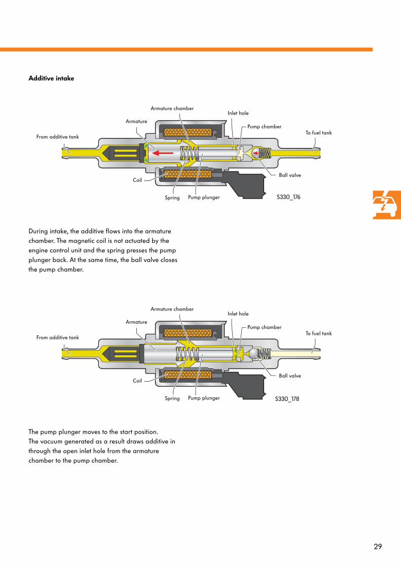
The particulate filter additive pump is of the reciprocating piston type, which delivers additive to the fuel tank. It can be found bolted on the additive tank.
Each time the fuel tank is replenished, the pump is actuated by the engine control unit in a cycle to ensure the correct amount of additive is added.
This is how it works:
Additive delivery
Coil
Armature
Pump plungerSpring
Inlet hole
Pump chamber
Ball valve
From additive tankTo fuel tank
S330_174
When not energised, the pump is filled with additive. As soon as the engine control unit actuates the particulate filter additive pump, the coil is energised and the armature moves the pump plunger against spring pressure. The pump plunger closes the inlet hole to the pump chamber and forces the additive in the chamber towards the ball valve.
This procedure results in a build up of pressure, which causes the ball valve and thereby the pump chamber to open. The volume of additive exactly metered by the size of the pump chamber is now delivered to the fuel tank.
29
Additive intake
Coil
Armature
Spring
Inlet hole
Pump chamber
Ball valve
From additive tankTo fuel tank
Pump plunger
Armature chamber
S330_176
During intake, the additive flows into the armature chamber. The magnetic coil is not actuated by the engine control unit and the spring presses the pump plunger back. At the same time, the ball valve closes the pump chamber.
Coil
Armature
Spring
Inlet hole
Pump chamber
Ball valve
From additive tankTo fuel tank
Pump plunger
Armature chamber
S330_178
The pump plunger moves to the start position. The vacuum generated as a result draws additive in through the open inlet hole from the armature chamber to the pump chamber.
30
Sensors and actuators
Diesel particulate filter warning lamp K231
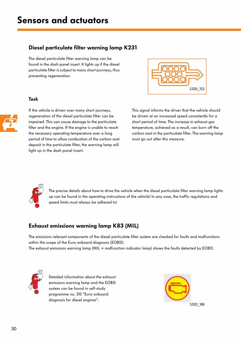
The diesel particulate filter warning lamp can be found in the dash panel insert. It lights up if the diesel particulate filter is subject to many short journeys, thus preventing regeneration.
S330_152
Task
If the vehicle is driven over many short journeys, regeneration of the diesel particulate filter can be impaired. This can cause damage to the particulate filter and the engine. If the engine is unable to reach the necessary operating temperature over a long period of time to allow combustion of the carbon soot deposit in the particulate filter, the warning lamp will light up in the dash panel insert.
This signal informs the driver that the vehicle should be driven at an increased speed consistently for a short period of time. The increase in exhaust gas temperature, achieved as a result, can burn off the carbon soot in the particulate filter. The warning lamp must go out after this measure.
The precise details about how to drive the vehicle when the diesel particulate filter warning lamp lights up can be found in the operating instructions of the vehicle! In any case, the traffic regulations and speed limits must always be adhered to!
Exhaust emissions warning lamp K83 (MIL)
The emissions relevant components of the diesel particulate filter system are checked for faults and malfunctions within the scope of the Euro onboard diagnosis (EOBD).The exhaust emissions warning lamp (MIL = malfunction indicator lamp) shows the faults detected by EOBD.
Detailed information about the exhaust emissions warning lamp and the EOBD system can be found in self-study programme no. 315 "Euro onboard diagnosis for diesel engines".
S330_188

31
N18 Exhaust gas recirculation valveN75 Charge pressure control solenoid valveV135 Particulate filter additive pump V157 Intake manifold flap motorZ19 Lambda probe heater
Colour coding/key= Input signal
= Output signal
= Positive
= Earth
= CAN data bus
Functional diagram
Functional diagram
Kl. 30
V135G39
Z19
J533
K231
J285
J248
G70G504 G507 G506
S S
J317
Kl. 15
S
G450
S330_170
G
N240 N241 N242 N243
S
V157N18 N75
G Fuel gauge senderG39 Lambda probe G70 Air mass meterG450 Exhaust gas sensor 1 G504 Fuel additive tank empty senderG506 Temperature sender before particulate filter G507 Temperature sender before turbocharger J248 Diesel direct injection system control unit J285 Control unit in dash panel insertJ317 Terminal 30 voltage supply relayJ533 Data bus diagnostic interfaceK231 Diesel particulate filter warning lampN240-N243 Unit injector valves
32
System limits
Frequent short trips
For the regeneration process to be initiated in the diesel particulate filter, the exhaust gas temperature is increased by the engine management system. In the event of frequent short trips, the exhaust gas temperature cannot reach a sufficient level. Regeneration cannot be carried out successfully. Subsequent regeneration procedures that are carried out with excessively high levels of carbon deposit can lead to overheating and damage to the particulate filter. The filter could also become blocked due to a high level of carbon deposit. This blockage in the filter could cause the engine to fail.In order to prevent these cases from happening, a diesel particulate filter warning lamp will be activated in the dash panel insert once a specific limit is reached in the filter storage capacity or after a certain number of unsuccessful regeneration procedures.
Detailed information about the particulate filter warning lamp can be found in this self-study programme on page 27.
The fuel qualityFor effective operation of the system, it is important that the specific ratio between additive and carbon deposit in the particulate filter is not too low. It should be noted that the fuel must meet DIN standards. Operation of the vehicle with biodiesel is not possible due to the quality of the fuel currently available and due to the considerably reduced oxidation stability.If the fuel contains a high level of sulphur, this can lead to impaired function of the particulate filter system with higher fuel consumption as a result of increased regeneration.
The emissionsWhen the regeneration cycle is active, there could be an increase in emissions. During regeneration, there is an oxidation process from carbon to carbon dioxide (CO2). If there is not enough oxygen available during this process, carbon monoxide (CO) will also be formed.
To determine the emissions content, an emissions test is carried out (NEDC - New European Driving Cycle).During this test, the values from the cycle are evaluated with and without regeneration. With the mean values, the vehicle must meet the EU4 emissions standard.

33
Service
Maintenance of the particulate filter
In addition to particles of carbon, ash is also collected in the particulate filter. This inorganic ash comprises of the remains from oil combustion and the iron-rich additive introduced in the fuel. Since the ash cannot be burnt, it reduces the effective filter volume and thereby impairs the function of the particulate filter over a certain period of time.The amount of ash collected in the diesel particulate filter is calculated by the engine control unit. The ash content reading can be taken using vehicle diagnosis, testing and information system VAS 5052 in a measured value block in "Guided fault finding" mode.At an average fuel consumption, the effective service life of the particulate filter is 120,000 km. If fuel consumption is increased, the diesel particulate filter's service life will be reduced, making it necessary to exchange the filter at 90,000 km.
Once the particulate filter has been exchanged, the ash content figure must be reset to zero using vehicle diagnosis, testing and information system VAS 5051. If the engine control unit is replaced, the old ash content reading stored in its memory must be copied using VAS 5051 and then saved in the new engine control unit. To do this, please refer to the instructions provided in the Electronic Service Information System (ELSA).
Maintenance of the additive tank
The size of the additive tank is designed to hold enough additive to cover 120,000 km with average fuel consumption.If fuel consumption is higher than average, the driver will be informed when the level of additive drops to 0.3 litres by the preglow control lamp and a fault message in the display of the dash panel insert, prompting him/her to drive to a workshop.The additive remains chemically stable for a period of 4 years, even under extreme climatic conditions. After 4 years, 120,000 km or if a warning is given in the dash panel insert, additive service measures become necessary. This involves purging of the tank content and replenishment with new additive.
Please refer to the safety measures in ELSA before performing service work on the additive tank.
34
Service
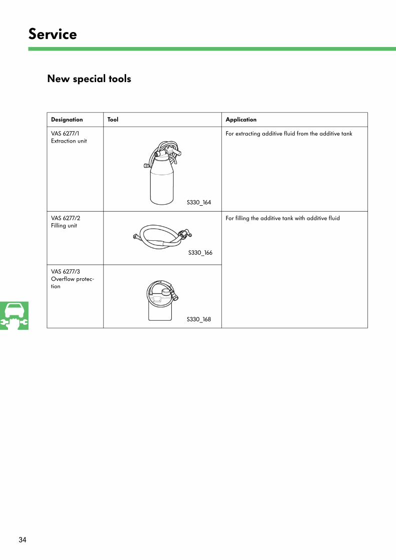
New special tools
Designation Tool Application
VAS 6277/1Extraction unit
For extracting additive fluid from the additive tank
VAS 6277/2 Filling unit
For filling the additive tank with additive fluid
VAS 6277/3 Overflow protec-tion
S330_164
S330_166
S330_168
35
Test yourself
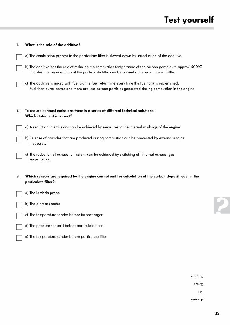
1. What is the role of the additive?
a) The combustion process in the particulate filter is slowed down by introduction of the additive.
b) The additive has the role of reducing the combustion temperature of the carbon particles to approx. 500°C in order that regeneration of the particulate filter can be carried out even at part-throttle.
c) The additive is mixed with fuel via the fuel return line every time the fuel tank is replenished.Fuel then burns better and there are less carbon particles generated during combustion in the engine.
2. To reduce exhaust emissions there is a series of different technical solutions. Which statement is correct?
a) A reduction in emissions can be achieved by measures to the internal workings of the engine.
b) Release of particles that are produced during combustion can be prevented by external engine measures.
c) The reduction of exhaust emissions can be achieved by switching off internal exhaust gas recirculation.
3. Which sensors are required by the engine control unit for calculation of the carbon deposit level in the particulate filter?
a) The lambda probe
b) The air mass meter
c) The temperature sender before turbocharger
d) The pressure sensor 1 before particulate filter
e) The temperature sender before particulate filter
Answers
1.) b
2.) a, b
3.)b, d, e
330
© VOLKSWAGEN AG, Wolfsburg, VK-21 Service Training
All rights reserved including the right to make technical changes
000.2811.46.20 Technical status 05/04
❀ This paper was manufactured from pulp that
was bleached without the use of chlorine.