ssp 890243 overview 4 1 2014 - vwcup-files.track360.com
TRANSCRIPT

Service Training
Self Study Program 890243
The 2015 GolfDesign and Function

Volkswagen Group of America, Inc.Volkswagen AcademyPrinted in U.S.A.Printed 3/2014
Course Number SSP 890243
©2014 Volkswagen Group of America, Inc.
All rights reserved. All information contained in this manual is based on the latest information available at the time of printing and is subject to the copyright and other intellectual property rights of Volkswagen Group of America, Inc., its affiliated companies and its licensors. All rights are reserved to make changes at any time without notice. No part of this document may be reproduced, stored in a retrieval system, or transmitted in any form or by any means, electronic, mechanical, photocopying, recording or otherwise, nor may these materials be modified or reposted to other sites without the prior expressed written permission of the publisher.
All requests for permission to copy and redistribute information should be referred to Volkswagen Group of America, Inc.
Always check Technical Bulletins and the latest electronic repair information for information that may supersede any information included in this booklet.
Trademarks: All brand names and product names used in this manual are trade names, service marks, trademarks, or registered trademarks; and are the property of their respective owners.

i
Contents
This Self-Study Program provides information regarding the design and function of new models.This Self-Study Program is not a Repair Manual. This information will not be updated.
For maintenance and repair procedures, always refer to the latest electronic service information.
Note Important!
Introduction . . . . . . . . . . . . . . . . . . . . . . . . . . . . . . . . . . . . . . . . . . . . . . . . . . . . 1
Body . . . . . . . . . . . . . . . . . . . . . . . . . . . . . . . . . . . . . . . . . . . . . . . . . . . . . . . . . . 8
Occupant Protection . . . . . . . . . . . . . . . . . . . . . . . . . . . . . . . . . . . . . . . . . . . . 10
Engines . . . . . . . . . . . . . . . . . . . . . . . . . . . . . . . . . . . . . . . . . . . . . . . . . . . . . . . 12
Transmissions . . . . . . . . . . . . . . . . . . . . . . . . . . . . . . . . . . . . . . . . . . . . . . . . . . 16
Heating and Air Conditioning . . . . . . . . . . . . . . . . . . . . . . . . . . . . . . . . . . . . 18
Electrical System . . . . . . . . . . . . . . . . . . . . . . . . . . . . . . . . . . . . . . . . . . . . . . . 28
Knowledge Assessment . . . . . . . . . . . . . . . . . . . . . . . . . . . . . . . . . . . . . . . . . 35

Page intentionally left blank

1
Introduction
The New Golf
The 2015 Golf is the first Volkswagen vehicle that uses a new platform concept, the Modular Transverse Matrix (MQB). Many of the mechanical units, subassemblies and systems have been completely re-developed. This seventh-generation Golf sets new standards in its vehicle class for convenience, quality and safety features, as well as the assistance systems available for the vehicle.
This Self-Study Program provides an overview of the design and function of the new Golf and help explain many of its technical innovations.
s513_001

2
Introduction
Modular Transverse Matrix (MQB)
The modular transverse matrix, or MQB, is the new modular strategy introduced by the Volkswagen Group. This modular transverse matrix will be used for the Volkswagen, Audi, SKODA and SEAT brands. Volkswagen will use it for the Polo, Beetle, Scirocco, Jetta, Tiguan, Touran, Sharan, Passat, Volkswagen CC and 2015 Golf.
Vehicle Architecture
The integral feature of the modular transverse matrix is a flexible vehicle architecture. This has been divided into five principle vehicle sections. Some sections are variable. One section is the same (uniform) for all vehicles.
• The central section is the area between the pedal cluster and wheel center. The central section dimension is based on a transverse engine position and is the same for all vehicles
• The variable dimensions are wheelbases, track widths, wheel sizes and seat positions
Module Families
The MQB is based on these modules:
• Electrics/electronics
• Drivetrain
• Running gear
• Vehicle design (vehicle body, air conditioning system, seat system, airbags)
Variable
VariableVariableVariable Uniform s513_003

3
Introduction
From Platform to Modular Matrix
Platform Strategy Module Strategy Modular Matrix Strategy
Synergies within just one vehicle class Synergies partly shared among vehicle classes
Synergies shared among all vehicle classes
Since the early 1990s, several different models have been produced on a shared platform.
This strategy involves dividing the vehicle into the body-in-white and the platform. The technical features of the platform components are virtually identical.
In 2000, the module strategy was used. Modules with basic technical functions and identical designs were used on multiple vehicles.
Since 2007, the use of modules has been extended to the entire vehicle and across all vehicle classes. From 2012 on, the same modules will be used across the entire Group for the modular strategy.
Body-in-white
PlatformModule Module
s513_070 s513_072 s513_074
Veh
icle
Cla
sses
Veh
icle
Cla
sses
Veh
icle
Cla
sses
Bodywork Shape Bodywork Shape Bodywork Shapes513_076 s513_078 s513_080
Standardization Across All Brands
Some of the advantages provided by standardization across all brands include:
• Production is faster, simpler, more cost-effective and more flexible. It simplifies development and creates synergies across all brands and vehicle models
• The modular matrix strategy allows the number of versions and version complexity to be reduced significantly
• Standardizes production processes that use the same body construction techniques, a uniform assembly sequence and uniform installation concepts
• Allows the production of MQB-designed vehicles on the same production line, even if they are made by different brands

4
Introduction
Production Sites
The 2015 Golf will be produced in the Volkswagen factories in Wolfsburg, Puebla and Zwickau.
The Wolfsburg Production Site
The production plant in Wolfsburg, which was built in 1938/1939, is the headquarters of the Volkswagen Group and the largest continuous automobile factory in the world.
The factory grounds, which are located next to the Mittelland Canal, are more than six square kilometers. Over 51,000 people are employed here. They are not only involved in the production of the Golf, but also the Golf Plus, Touran and Tiguan. In 2011, a total of 805,000 vehicles left this factory’s production halls. The Wolfsburg plant has produced around 40 million vehicles to date.
The Zwickau Production Site
The Zwickau plant is an automobile factory located in Saxony. It was founded in 1990 and is combined with the Chemnitz engine factory. The factory grounds cover approximately 1.8 square kilometers. The Golf and Passat models as well as bodies for Bentley and Phaeton are produced here. A combined number of about 8,100 employees work in Zwickau and Chemnitz.
s513_009
s513_007
The Puebla Production Site
The 2012 Beetle is built at Volkswagen’s Puebla, Mexico plant. This plant began operation in 1964, manufacturing the old style Beetle.
Currently, the Puebla plant employs approximately 15,000 people and produces the New Jetta, Beetle, Golf and other vehicles.

5
Introduction
The Golf Innovations
The MQB concept reduces the weight of the 2015 Golf by up to 100 kg (220 lb) compared to the previous models. This weight savings reduces fuel consumption and CO2 emissions.
Some new technologies used on this platform are:
• A new series of engines
• Modular Infotainment System (MIB)
• ergoActive seat design
• Panorama sliding/tilting sunroof
• Xenon headlights
• Proactive occupant protection
• Driving mode selection (GTI only)
s513_015

6
Introduction
855mm (33.7in) 2637mm (103.1in) 763mm (30.0in)
4255mm (167.5in)14
52m
m (5
7.2i
n)
1549mm (60.1in)
s513_017
1520mm (59.8in)
Technical DataExterior Dimensions and Weights
Exterior Dimensions Weights/Further Data
2010 Golf 2015 Golf
Length 4199 mm165.3 in
4255 mm167.5 in
Width 1786 mm79.3 in
1799 mm70.8 in
Height 1480 mm58.3 in
1452 mm57.2 in
Wheelbase 2578 mm101.5 in
2637 mm103.1 in
Track Width at Front 1541 mm60.6 in
1549 mm60.1 in
Track Width at Rear 1514 mm59.6 in
1520 mm59.8 in
2010 Golf 2015 Golf
GVWR 1780 kg3924 lb
1870 kg4123 lb
Curb Weight 1154 kg2544 lb
1315 kg2901 lb
Max. Roof Load 75 kg165 lb
75 kg165 lb
Turning Radius 10.9 meters35.8 feet
10.9 meters35.8 feet
Tank Capacity 55 liters14.5 gallons
50 liters13.2 gallons
Drag Coefficient 0.312 cw 0.287 cw*
Based on a 1.8T with a manual transmission.

7
Introduction
1018
mm
967m
m
1750mm
1023mm
2006
mm
643
mm
665
mm
Interior Dimensions and Volumes
s513_019
Interior Dimensions and Volumes
2010 Golf 2015 Golf
Luggage Compartment Volume
350 liters12.4 ft3
388 liters13.7 ft3
Luggage Compartment Volume with Rear Seat Backrest Folded Down
1305 liters46.1 ft3
1337 liters47.2 ft3
Height of Luggage Compartment Opening
659 mm26.0 in
643 mm25.3 in
Width of Luggage Compartment Opening
976 mm38.4 in
1023 mm40.3 in
2010 Golf 2015 Golf
Max. Front Headroom 987 mm38.9 in
975 mm38.4 in
Rear Headroom 979 mm38.5 in
967 mm38.1 in
Knee Room - Rear Seat 901 mm35.5 in
904 mm35.6 in

8
Body
Body Structure
One design goal of the vehicle was to combine high crash safety with low body weight. In order to make this goal a reality, a high proportion of ultra-high tensile (thermoformed) sheet metal parts are used. In addition, innovative production technologies, such as the "tailored rolled blank technique," and new joining technologies, such as the "wobble seams" in the side area, have been used. This has increased the stability of the passenger compartment.
Wobble Seams
Wobble seams (the name refers to their shape) are being use for the first time in the 2015 Golf. This joining technology produces a longer laser weld over the same area. It can be subjected to a load three to four times greater than individual spot welds.
Wobble Seam
s513_023
Strengths of Steel Sheets
<Up to 23,000 psi (160MPa) <Up to 32,000 psi (220MPa) <Up to 61,000 psi (420MPa) <Up to 145,000 psi (1000MPa) >Over 145,000 psi (1000 MPa) ultra-high tensile (thermoformed)

9
Body
Tailor Rolled Blank Technology
The B-pillar uses "tailored blank technology." This involves varying the thickness of the steel parts. Each part can be thicker or thinner in certain areas, depending on the strength required.
Manufacturing Process
Blanks
s513_027
s513_025

10
Occupant Protection
Safety Equipment
The 2015 Golf has the following safety equipment:
• Single-stage driver airbag
• Single-stage, disengagable front passenger airbag
• Front side airbags
• Head curtain airbags
• Three-point automatic front seat belt with tensioner
• Three-point rear automatic seat belt
• Front belt force limiter
• Top tether

11
Occupant Protection
s513_029
Crash Sensors
• Crash sensor for front airbag
• Crash sensors in the doors for side crash detection (pressure sensors)
• Crash sensors in the C-pillars for side crash detection (acceleration sensors)

12
Engines
s513_056
2.0L TDI Engine
Technical Features
• Camshaft bearings in camshaft housing (modular design)
• Oil pump and vacuum pump in one housing with a shared drive shaft
• Thermal management with switchable coolant pump
• Intake manifold with water-cooled charge air cooler
• Exhaust purification module with integrated oxidizing catalytic converter and diesel particulate filter
• Low pressure exhaust gas recirculation
• Balance shaft integrated in the cylinder block
Engine Code CRBC
Design 4-cylinder inline engine
Displacement 1968 cm3
Bore 81.0 mm
Stroke 95.5 mm
Valves per Cylinder 4
Compression Ratio 16.2:1
Max. Output150 hp (110kW) from 3500 - 4000 rpm
Max Torque235 lb.ft (320 Nm) from 1750 - 3000 rpm
Engine Management Bosch EDC 17
Fuel Ultra-Low Sulfur Diesel
Exhaust Gas After-treatment
Exhaust gas recirculation, oxidizing catalytic converter, diesel particulate filter
Emissions Standard BIN5
Technical Data
S514_100
2.0 TDI Engine
1000 2000 3000 4000
250
220
190
160
130
100
75
45
280 150
130
125
100
80
60
40
25
10
Torq
ue [l
b/ft]
Engine speed [rpm]
Out
put [
hp]

13
Engines
1.8L and 2.0L TSI Engines
The 1.8L engine will be used in the Golf. The 2.0L will be used in the GTI
Technical Data
Torque
Displacement 1798 cm3 1984 cm3
Bore 82.5 mm 82.5 mm
Stroke 84.1 mm 92.8 mm
Valves Per Cylinder 4
Compression Ratio 9.6:1
Horsepower 125 kW (170 hp) from 3,800 to 6,200 rpm
169 kW (220 hp) from 4,700 to 6,200 rpm
Torque 320 Nm (235 lb/ft)from 1,400 to 3,700 rpm
350 Nm (260 lb/ft) from 1,500 to 4,600 rpm
Engine Management
SIMOS 18.1
Fuel Premium
Emission Treatment Three-way catalytic converter, one upstream broadband lambda probe of the turbocharger and one step-type lambda probe downstream of the catalytic converter
Emission Standard SULEV
260
300
180
140
100
0
220
340
120
140
80
60
40
0
100
1000 2000 3000 4000 5000 6000
250 160
180
200
220
380280
420310
460340
135
160
190
220
75
105
250
280
310
340
135
160
190
220
75
105
Power
Lb/ft Nm kW Horsepower
1.8L Torque
1.8L Power
2.0L Torque
2.0L Power
Technical Features
• Cylinder head with integrated exhaust manifold
• Roller bearing balance shafts
• Smaller crankshaft main bearings with only four counterweights
• Turbocharger with electrical wastegate flap actuation
• Reduced oil pressure
• Sump with upper aluminum section and lower plastic section
• Accessory bracket with integrated oil filter and oil cooler
• Total weight savings of 7.8 kg (17.2 lb)s522_123

14
Engines
Misfueling Prevention for Diesel Vehicles
On diesel vehicles, an insert with a mechanical locking flap is in the filler neck for the fuel tank. This flap prevents a smaller nozzle from opening the filler flap, preventing diesel vehicles from being filled with the wrong fuel.
s513_120
Misfueling Prevention Device
Filler Neck
Design
View from Front View from Rear
s513_092 s513_094
Flap with Spring
Tabs
Plastic Ring with Annular Spring
Tabs Plastic Ring with Annular Spring
Flap with Spring
The Environmental Protection Agency (EPA) does not dictate specific nozzle sizes for different fuel types. The customer should always pay attention to the fuel type being put into the vehicle.

15
Engines
Function
If a diesel fuel nozzle is inserted into the filler neck of the fuel tank, the fuel nozzle pushes all the tabs in the misfueling prevention device to the side. The plastic ring is splayed and the locking lugs are forced apart. The force of the fuel nozzle during insertion opens the flap. The diesel fuel nozzle can now be fully inserted into the filler neck and the vehicle can be refilled with diesel fuel.
When the diesel fuel nozzle is pulled out of the misfueling prevention device, the flap is closed by the force of the springs. The force of the annular springs contracts the plastic ring and locks the flap using the locking lugs.
The a smaller fuel nozzle will not force all the tabs in the plastic ring apart. The plastic ring will not be splayed and the locking lugs cannot release the flap. The prevents the insertion of the smaller fuel nozzle.
A larger fuel nozzle will not be able to be inserted deep enough into the filler neck to force the tabs apart.
Filling with Fuel Can
If the fuel tank needs to be filled using a fuel can, the flap will not open. The tank can only be filled as the fuel flows into the filler neck between the tabs and flap. This results in very slow filling.
s513_118
Space Between the Tabs and the Flap
Tabs
Locking LugsPlastic Ring
Flap
Diesel Fuel Nozzle
s513_116

16
Transmissions
6-Speed Manual Transmission • MQ350-6F 02Q
• Based on the 02M transmission
• Changes to selector shaft, selector forks with stops in housing, modified bearings
• No speedometer sender
• Torque capacity up to 350 Nm
5-Speed Manual Transmission • MQ250-5F 02SF
• Based on the 0A4
• Longer shafts with additional bearings, additional gear pair, new longer housing lid made from aluminium
• No speedometer sender
• Torque capacity up to 250 Nm
6-Speed
Dual-Clutch Transmission
• DQ250-6F DSG 02E
• The 6-speed dual clutch transmission
• Hydraulic dual clutch
• High level of efficiency as well as sturdiness and sportiness of a manual transmission
• High level of comfort of an automatic gearbox during gear changes.
6-Speed Automatic Transmission • 09G based on previous 09G/09M automatic transmsission
• New Automatic Transmission Fluid (ATF) cannot be mixed with some previous 09G/09M automatic transmission fluids. Always reference the correct part number in ETKA
• Redesigned valve body

17
Transmissions
With the introduction of the modular transverse matrix, the connection between the engine and the transmission has been changed, and a new engine mounting point has been added.
Selector Lever
The selector lever features a new option for changing from selector position "D" to "S" and vice-versa. The change is made by tapping it backwards once. The selector lever then springs back into the D/S position.
s513_098
s513_096
Additional Engine Bolt Point
18
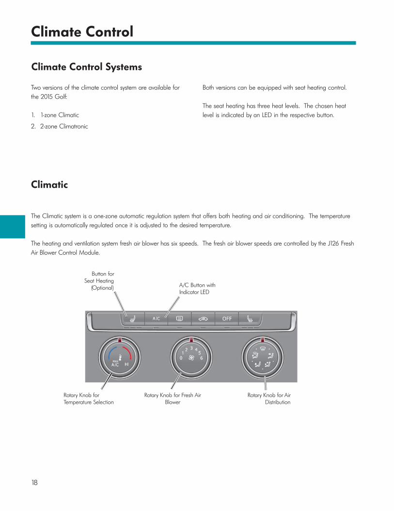
Climate Control
Climatic
Button forSeat Heating
(Optional)
Rotary Knob forTemperature Selection
Rotary Knob for Fresh AirBlower
Rotary Knob for AirDistribution
A/C Button withIndicator LED
The Climatic system is a one-zone automatic regulation system that offers both heating and air conditioning. The temperature setting is automatically regulated once it is adjusted to the desired temperature.
The heating and ventilation system fresh air blower has six speeds. The fresh air blower speeds are controlled by the J126 Fresh Air Blower Control Module.
Two versions of the climate control system are available for the 2015 Golf:
1. 1-zone Climatic
2. 2-zone Climatronic
Both versions can be equipped with seat heating control.
The seat heating has three heat levels. The chosen heat level is indicated by an LED in the respective button.
Climate Control Systems

19
Climate Control
Powertrain CAN-BusRunning Gear CAN-BusConvenience CAN-BusCAN Data-Bus LineLIN Data-Bus LineSensor LineActuator Line
Legend
EX21 Heater and A/C ControlsG92 Temperature Regulator Door Motor Position SensorG308 Evaporator Temperature SensorG645 Air Distribution Door Motor Position SensorG805 Refrigerant Circuit Pressure SensorJ126 Fresh Air Blower Control ModuleJ301 A/C Control ModuleJ519 Vehicle Electrical System Control ModuleJ533 Data Bus on Board Diagnostic InterfaceN280 A/C Compressor Regulator ValveV2 Fresh Air BlowerV68 Temperature Regulator Door MotorV113 Recirculation Door MotorV428 Air Distribution Door Motor
Powertrain CAN-Bus Running Gear CAN-Bus
Convenience CAN-Bus
LIN
Climatic Network Diagram

20
Climate Control
2-Zone Climatronic
The Climatronic allows for different temperature settings for the driver and passenger sides of the vehicle. The temperature settings range from 61°F to 85° F (16° C to 29.5° C).
It is operated using the following buttons:
• SETUP: Opens the climate menu in the operating and display unit for the Infotainment system, allowing the climate profile and AUTO air recirculation to be set.
• AUTO: Automatic regulation of blowers, temperature and air distribution according to the intensity of the sun, outside and inside temperature and humidity.
• MAX Defrost: Maximum blower power, air distribution is directed towards the windows.
• SYNC: Synchronizes the climate zones with the driver value.
• MAX A/C: Temperature setting to “LO,” maximum blower power, air distribution to the occupant vents.
s513_046
Rotary Knob for the Left-Hand Climate Zone Temperature Setting
Rotary Knob for the BlowerStrength Setting
Rotary Knob for the Right-Hand ClimateZone Temperature Setting
Seat Heating Button (Optional)

21
Climate Control
Climatronic Network Diagram
Powertrain CAN-Bus Running Gear CAN-Bus
Convenience CAN-Bus
LIN
LIN
s513_205
Powertrain CAN-BusRunning gear CAN-BusConvenience CAN-BusCAN Data-Bus LineLIN Data-Bus LineSensor LineActuator Line
Legend
EX21 Heater and A/C ControlsG17 Outside Air Temperature SensorG107 Sunlight Photo SensorG135 Defroster Door Motor Position SensorG150 Left Vent Temperature SensorG151 Right Vent Temperature SensorG192 Footwell Vent Temperature SensorG220 Left Temperature Door Potentiometer/ActuatorG221 Right Temperature Door Potentiometer/ActuatorG238 Air Quality SensorG260 A/C Humidity SensorG308 Evaporator Temperature SensorG642 Front Air Distribution Door Motor Position SensorG644 Fresh Air/Recirculating Air/Back Pressure Door Motor Position SensorG805 Refrigerant Circuit Pressure SensorJ126 Fresh Air Blower Control ModuleJ255 Climatronic Control ModuleJ519 Vehicle Electrical System Control ModuleJ533 Data Bus on Board Diagnostic Interface
J623 Engine Control ModuleN280 A/C Compressor Regulator ValveV2 Fresh Air BlowerV107 Defroster Door MotorV158 Left Temperature Door MotorV159 Right Temperature Door MotorV425 Fresh Air/Recirculating Air/Back Pressure Door MotorV426 Front Air Distribution Door Motor

22
Climate Control
Climate Profiles
The Infotainment display head is used to set the climate profile. The following three climate profiles are available for selection:
1. Gentle
2. Average
3. Intensive
A map has been stored for each individual climate profile. Depending on the climate profile selected, the airflow is regulated using the fresh air blower speed.
The time needed to respond to disturbances varies between the climate profiles. For example, the intensive climate profile reacts quickly using higher blower speeds and inputs from the sunlight sensor. The gentle profile keeps air flow and sounds from the blower motor low.
Air Conditioning System Sensors G17 Outside Air Temperature Sensor
Installation Location
G17 is located behind the front bumper.
Function
The temperature is measured by NTC thermistors.
Signal Analysis
The signal is transmitted to the J519 Vehicle Electrical System Control Module which transmits it to the J255 via the convenience CAN-Bus.
During diagnosis, the ambient temperature can be set. This can be helpful when bringing a cold vehicle (ex. one that has been sitting outside on the lot in 32° F (0° C) temperatures) into a warm shop environment. The ambient air temperature sensor may take some time to register the warmer shop air temperature, delaying diagnostic procedures. Entering the shop temperature using Guided Functions allows you to begin diagnosis faster.
Effects of Failure
The J255 Climatronic Control Module assumes a defined temperature value of 32° F (0° C). The air conditioning system operates using this value.
s513_022

23
Climate Control
G805 Refrigerant Circuit Pressure Sensor
Installation Location
G805 replaces the High Pressure Sensor G65. It is located in the high-pressure line between the condenser and the expansion valve. G805 is connected directly to the Climatic/Climatronic Control Module by a LIN bus.
Signal Utilization
The actual refrigerant pressure in the refrigerant circuit and the required engine load is calculated using the signals.
DSO Waveform
The Digital Storage Oscilloscope (DSO) waveform looks completely different from the previous G65 waveform.
Effects of Failure
If the pressure signal fails, the cooling function is deactivated.
s513_110
DSO waveform of the new G805.
s513_112
s513_114
For comparison: DSO waveform of the old G65

24
Climate Control
A/C Humidity Sensor G260
Installation Location
Only the Climatronic systems have the A/C Humidity Sensor G260. It is installed in the base of the interior mirror, combined with the rain/light sensor.
Design and Functional Principle
The humidity and the temperature at the window are measured using a capacitive thin-layer sensor. The sensor functions like a plate capacitor; measurement of the capacity indicates the degree of humidity.
Signal Utilization
The sensor determines:
• The inside windshield temperature
• The inside relative humidity
The signals are sent to the J519, then through the Convenience CAN-Bus to J255. J255 uses the signals to calculate the internal dew point.
To reduce windshield fogging, the Climatronic system influences:
• Turns the compressor ON or OFF
• Opens or closes defroster flaps
• Changes the fresh air blower speed for air quantity regulation
• Changes the evaporator temperature
• Controls the air recirculation flap between the recirculation or fresh air positions
Effects of Failure
Without the sensor signal, J255 cannot detect the dew point. The automatic defrost function fails.
s513_010
s513_012

25
Climate Control
Climate Control Components
Heater and Air Conditioning Units
Two versions are used in the 2015 Golf:
• The 1-zone heater and air conditioning unit for the Climatic system
• The 2-zone heater and air conditioning unit for the 2-zone Climatronic system
The dust and pollen filter is now mounted horizontally. It is accessed through the glove compartment, after the glove compartment has been placed in a "service position.”
Manufacturer Versions
Denso and Valeo both provide heating and air conditioning components for the Golf. The manufacturer of the components can only be identified by the heater pipe connections on the heater core. This is important because the control motors for actuating the individual air flaps are different for Denso and Valeo. These components cannot be interchanged and the correct replacement manufacturer’s parts must be ordered.
Remove the left front center console trim to expose the heater connections.
s513_201
s513_202
Denso Heating Pipe Connection
Valeo Heating Pipe Connection

26
Climate Control
Internal Heat Exchanger
The 2015 Golf has the "Internal heat exchanger" (IWT), which is also used in the Volkswagen Touareg. This is a refrigerant line that forms a "pipe-in-pipe system".
This refrigerant line has a low-pressure line inside of a high-pressure line. The refrigerant flows through the outer line to the expansion valve (high pressure), and flows back from the expansion valve through the inner line towards the air conditioner compressor (low pressure).
This design transfers the heat between the high and low pressure systems, increasing efficiency and reducing fuel consumption.
s513_008
s513_062
High Pressure
Low Pressure

Page intentionally left blank

28
Electrical Systems
Electrical Systems
This overview describes standard and optional electrical system features for the 2015 Golf.
Electrical Systems:
• All CAN-Bus systems operate at 500 kBit/s
• The multifunction steering wheel is available in different versions:
– Normal multifunction steering wheel
– Multifunction steering wheel with cruise control system (GRA)
• The dash panel insert is available in three different versions:
– Dash panel insert with multi-function display (MFD)
– Dash panel insert with MFD Plus
– Dash panel insert with MFD Premium
• Immobilizer V (fifth generation)
• Component protection
• Rearview camera
• Modular Infotainment System (MIB)

29
Electrical Systems
s513_013

30
Electrical Systems
Network Design
This networking diagram shows how the control modules communicate. All CAN-Bus lines transmit at 500 kBit/s.
Legend
J104 ABS Control ModuleJ250 Electronic Damping Control ModuleJ285 Instrument Cluster Control ModuleJ362 Anti-theft Immobilizer Control ModuleJ412 Cell Phone Operating Electronics Control ModuleJ446 Parking Aid Control Module (connected to J791)J453 Multifunction Steering Wheel Control ModuleJ500 Power Steering Control ModuleJ533 Data Bus on Board Diagnostic InterfaceJ540 Electromechanical Parking Brake Control ModuleJ667 Left Headlamp Power Output StageJ668 Right Headlamp Power Output StageJ685 Front Information Display Control Head J745 Cornering Lamp and Headlamp Range Control ModuleJ844 Automatic High Beam Assist Control ModuleJ981 Electronic Stabilization Program (ESP) Control Module
J794 Information Electronics Control Module 1R Radio (connected to J794 and series display J685 on the infotainment CAN-Bus)R189 Rearview CameraT16 16-Pin Connector CSCC Color Video LineLVDS Low Voltage Differential Signalling; Standard interface for high speed data transmissionAFS Cornering Light CAN data busSF Sensor Fusion CAN-Bus
s513_036MIB-CAN
LVDS
CSCCAFS
LIN data bus lineCAN-Bus line
Infotainment CAN-BusExtended CAN-BusPowertrain CAN-Bus
Running gear CAN-BusConvenience CAN data bus

31
Electrical Systems
Note the addition of the running gear CAN-Bus extended CAN-Bus. J533 is the LIN energy management and J453 master.
A cornering light CAN-Bus (Advanced Frontlighting System, AFS) is located between J745 and the Left/Right Headlamp Power Output Stages J667 and J668.
In the infotainment CAN-Bus, J685 is connected to J794 by the MIB CAN-Bus (a new subordinate Can-Bus system) and a Low Voltage Differential Signalling (LVDS) line (depending on equipment version).

32
Electrical Systems
Fuse Boxes and Relay Locations in the Electrical SystemThe battery is located on the left side of the engine compartment.
Generator
Acid Level Indicator
Battery

33
Electrical Systems
Fuse Box in the Engine Compartment
Multifuse
On-Board Supply Control Unit
Fuse Box in the Passenger Compartment.
• The fuse box is on the left side of the passenger compartment. The Vehicle Electrical System Control Module J519 is located next to the passenger compartment fuse box
• Fuse box in the engine compartment in front of the battery, with Multifuse
s513_021

Important Links
www.vwwebsource.com
https://www.datarunners.net/vw_crc/default.asp?pageid=home
www.vwhub.com

35
Knowledge Assessment
An on-line Knowledge Assessment (exam) is available for this Self-Study Program.
The Knowledge Assessment may or may not be required for Certification.
You can find this Knowledge Assessment at:
www.vwwebsource.com
For Assistance, please call:
Volkswagen Academy
Certification Program Headquarters
1-877-791-4838
(8:00 a.m. to 8:00 p.m. EST)
Or, E-mail:

Volkswagen Group of America2200 Ferdinand Porsche DriveHerndon, VA 20171March 2014